EP3267107A1 - Method of controlling a gas turbine assembly - Google Patents
Method of controlling a gas turbine assembly Download PDFInfo
- Publication number
- EP3267107A1 EP3267107A1 EP16178756.9A EP16178756A EP3267107A1 EP 3267107 A1 EP3267107 A1 EP 3267107A1 EP 16178756 A EP16178756 A EP 16178756A EP 3267107 A1 EP3267107 A1 EP 3267107A1
- Authority
- EP
- European Patent Office
- Prior art keywords
- combustor
- tfl1
- turbine assembly
- gas turbine
- gas
- Prior art date
- Legal status (The legal status is an assumption and is not a legal conclusion. Google has not performed a legal analysis and makes no representation as to the accuracy of the status listed.)
- Granted
Links
Images

Classifications
-
- F—MECHANICAL ENGINEERING; LIGHTING; HEATING; WEAPONS; BLASTING
- F02—COMBUSTION ENGINES; HOT-GAS OR COMBUSTION-PRODUCT ENGINE PLANTS
- F02C—GAS-TURBINE PLANTS; AIR INTAKES FOR JET-PROPULSION PLANTS; CONTROLLING FUEL SUPPLY IN AIR-BREATHING JET-PROPULSION PLANTS
- F02C9/00—Controlling gas-turbine plants; Controlling fuel supply in air- breathing jet-propulsion plants
- F02C9/26—Control of fuel supply
- F02C9/28—Regulating systems responsive to plant or ambient parameters, e.g. temperature, pressure, rotor speed
-
- F—MECHANICAL ENGINEERING; LIGHTING; HEATING; WEAPONS; BLASTING
- F02—COMBUSTION ENGINES; HOT-GAS OR COMBUSTION-PRODUCT ENGINE PLANTS
- F02C—GAS-TURBINE PLANTS; AIR INTAKES FOR JET-PROPULSION PLANTS; CONTROLLING FUEL SUPPLY IN AIR-BREATHING JET-PROPULSION PLANTS
- F02C3/00—Gas-turbine plants characterised by the use of combustion products as the working fluid
- F02C3/04—Gas-turbine plants characterised by the use of combustion products as the working fluid having a turbine driving a compressor
-
- F—MECHANICAL ENGINEERING; LIGHTING; HEATING; WEAPONS; BLASTING
- F02—COMBUSTION ENGINES; HOT-GAS OR COMBUSTION-PRODUCT ENGINE PLANTS
- F02C—GAS-TURBINE PLANTS; AIR INTAKES FOR JET-PROPULSION PLANTS; CONTROLLING FUEL SUPPLY IN AIR-BREATHING JET-PROPULSION PLANTS
- F02C3/00—Gas-turbine plants characterised by the use of combustion products as the working fluid
- F02C3/14—Gas-turbine plants characterised by the use of combustion products as the working fluid characterised by the arrangement of the combustion chamber in the plant
-
- F—MECHANICAL ENGINEERING; LIGHTING; HEATING; WEAPONS; BLASTING
- F02—COMBUSTION ENGINES; HOT-GAS OR COMBUSTION-PRODUCT ENGINE PLANTS
- F02C—GAS-TURBINE PLANTS; AIR INTAKES FOR JET-PROPULSION PLANTS; CONTROLLING FUEL SUPPLY IN AIR-BREATHING JET-PROPULSION PLANTS
- F02C7/00—Features, components parts, details or accessories, not provided for in, or of interest apart form groups F02C1/00 - F02C6/00; Air intakes for jet-propulsion plants
- F02C7/04—Air intakes for gas-turbine plants or jet-propulsion plants
-
- F—MECHANICAL ENGINEERING; LIGHTING; HEATING; WEAPONS; BLASTING
- F23—COMBUSTION APPARATUS; COMBUSTION PROCESSES
- F23N—REGULATING OR CONTROLLING COMBUSTION
- F23N1/00—Regulating fuel supply
- F23N1/002—Regulating fuel supply using electronic means
-
- F—MECHANICAL ENGINEERING; LIGHTING; HEATING; WEAPONS; BLASTING
- F23—COMBUSTION APPARATUS; COMBUSTION PROCESSES
- F23N—REGULATING OR CONTROLLING COMBUSTION
- F23N5/00—Systems for controlling combustion
- F23N5/02—Systems for controlling combustion using devices responsive to thermal changes or to thermal expansion of a medium
- F23N5/022—Systems for controlling combustion using devices responsive to thermal changes or to thermal expansion of a medium using electronic means
-
- F—MECHANICAL ENGINEERING; LIGHTING; HEATING; WEAPONS; BLASTING
- F23—COMBUSTION APPARATUS; COMBUSTION PROCESSES
- F23R—GENERATING COMBUSTION PRODUCTS OF HIGH PRESSURE OR HIGH VELOCITY, e.g. GAS-TURBINE COMBUSTION CHAMBERS
- F23R3/00—Continuous combustion chambers using liquid or gaseous fuel
- F23R3/28—Continuous combustion chambers using liquid or gaseous fuel characterised by the fuel supply
- F23R3/34—Feeding into different combustion zones
- F23R3/346—Feeding into different combustion zones for staged combustion
-
- F—MECHANICAL ENGINEERING; LIGHTING; HEATING; WEAPONS; BLASTING
- F05—INDEXING SCHEMES RELATING TO ENGINES OR PUMPS IN VARIOUS SUBCLASSES OF CLASSES F01-F04
- F05D—INDEXING SCHEME FOR ASPECTS RELATING TO NON-POSITIVE-DISPLACEMENT MACHINES OR ENGINES, GAS-TURBINES OR JET-PROPULSION PLANTS
- F05D2220/00—Application
- F05D2220/30—Application in turbines
- F05D2220/32—Application in turbines in gas turbines
-
- F—MECHANICAL ENGINEERING; LIGHTING; HEATING; WEAPONS; BLASTING
- F05—INDEXING SCHEMES RELATING TO ENGINES OR PUMPS IN VARIOUS SUBCLASSES OF CLASSES F01-F04
- F05D—INDEXING SCHEME FOR ASPECTS RELATING TO NON-POSITIVE-DISPLACEMENT MACHINES OR ENGINES, GAS-TURBINES OR JET-PROPULSION PLANTS
- F05D2240/00—Components
- F05D2240/35—Combustors or associated equipment
-
- F—MECHANICAL ENGINEERING; LIGHTING; HEATING; WEAPONS; BLASTING
- F05—INDEXING SCHEMES RELATING TO ENGINES OR PUMPS IN VARIOUS SUBCLASSES OF CLASSES F01-F04
- F05D—INDEXING SCHEME FOR ASPECTS RELATING TO NON-POSITIVE-DISPLACEMENT MACHINES OR ENGINES, GAS-TURBINES OR JET-PROPULSION PLANTS
- F05D2240/00—Components
- F05D2240/60—Shafts
-
- F—MECHANICAL ENGINEERING; LIGHTING; HEATING; WEAPONS; BLASTING
- F05—INDEXING SCHEMES RELATING TO ENGINES OR PUMPS IN VARIOUS SUBCLASSES OF CLASSES F01-F04
- F05D—INDEXING SCHEME FOR ASPECTS RELATING TO NON-POSITIVE-DISPLACEMENT MACHINES OR ENGINES, GAS-TURBINES OR JET-PROPULSION PLANTS
- F05D2270/00—Control
- F05D2270/30—Control parameters, e.g. input parameters
- F05D2270/301—Pressure
- F05D2270/3013—Outlet pressure
-
- F—MECHANICAL ENGINEERING; LIGHTING; HEATING; WEAPONS; BLASTING
- F05—INDEXING SCHEMES RELATING TO ENGINES OR PUMPS IN VARIOUS SUBCLASSES OF CLASSES F01-F04
- F05D—INDEXING SCHEME FOR ASPECTS RELATING TO NON-POSITIVE-DISPLACEMENT MACHINES OR ENGINES, GAS-TURBINES OR JET-PROPULSION PLANTS
- F05D2270/00—Control
- F05D2270/30—Control parameters, e.g. input parameters
- F05D2270/303—Temperature
-
- F—MECHANICAL ENGINEERING; LIGHTING; HEATING; WEAPONS; BLASTING
- F05—INDEXING SCHEMES RELATING TO ENGINES OR PUMPS IN VARIOUS SUBCLASSES OF CLASSES F01-F04
- F05D—INDEXING SCHEME FOR ASPECTS RELATING TO NON-POSITIVE-DISPLACEMENT MACHINES OR ENGINES, GAS-TURBINES OR JET-PROPULSION PLANTS
- F05D2270/00—Control
- F05D2270/30—Control parameters, e.g. input parameters
- F05D2270/304—Spool rotational speed
-
- F—MECHANICAL ENGINEERING; LIGHTING; HEATING; WEAPONS; BLASTING
- F23—COMBUSTION APPARATUS; COMBUSTION PROCESSES
- F23N—REGULATING OR CONTROLLING COMBUSTION
- F23N2229/00—Flame sensors
-
- F—MECHANICAL ENGINEERING; LIGHTING; HEATING; WEAPONS; BLASTING
- F23—COMBUSTION APPARATUS; COMBUSTION PROCESSES
- F23R—GENERATING COMBUSTION PRODUCTS OF HIGH PRESSURE OR HIGH VELOCITY, e.g. GAS-TURBINE COMBUSTION CHAMBERS
- F23R2900/00—Special features of, or arrangements for continuous combustion chambers; Combustion processes therefor
- F23R2900/03341—Sequential combustion chambers or burners
Definitions
- the present invention relates to a method of controlling a gas turbine assembly.
- the present invention relates to a method of controlling a gas turbine assembly with sequential combustion during start up and similar transient phases.
- gas turbine assemblies with sequential combustion are generally provided with two combustors and with a high-pressure intermediate turbine which is interposed between the two combustors for subjecting the flow of hot gasses moving from first to second combustor to a partial expansion that reduces the temperature of the hot gasses.
- the combustor start-up sequence is usually controlled according to a mapping table based on the gas temperature at the outlet of the intermediate turbine, hereinafter referred to as TAT1, and on the ratio between the fuel mass flow-rate supplied to the pilot flame of the first combustor and the total fuel mass flow-rate supplied to the first combustion chamber on the measured temperature TAT1, hereinafter referred to as SIR, which is function of the thermal state of the compressor of gas turbine assembly.
- fuel is timely supplied to first and/or second combustor according to a predefined schedule based on a fixed TAT1 value.
- the TAT1 schedule is usually defined during on-field tests and often needs to be adjusted on site in order to match the real operating conditions of the gas turbine assembly and to improve the startup behavior of combustors.
- tune up of the TAT1 schedule is very difficult because engine parameters (i.e. air and fuel mass flow-rates, pressures, temperatures, turbine rotational speed, etc.) are used to change continuously. Also the thermal state of the engine plays an important role (warm or cold engine) and it adds a further variable to the tune-up procedure.
- engine parameters i.e. air and fuel mass flow-rates, pressures, temperatures, turbine rotational speed, etc.
- thermal state of the engine plays an important role (warm or cold engine) and it adds a further variable to the tune-up procedure.
- TAT1 parameter in fact is measured faraway downstream of the first combustor and thus it may not reveal sudden variations of the flame temperature inside the combustor, and these sudden changes in flame temperature inside the combustor can lead to flame instabilities, lean blowout phenomena (generally known as LBO) and/or pressure pulsations, with all problems that this entails.
- LBO lean blowout phenomena
- Aim of the present invention is to avoid the drawbacks connected to currently-used fixed-TAT1 schedules.
- a method for controlling a gas turbine assembly comprising: a compressor in which compression of the outside air occurs for producing a flow of compressed air; a sequential combustor including a first combustor in which combustion of a mixture of fuel and compressed air arriving from said compressor occurs for producing a flow of hot gasses and a second combustor (7) which is located downstream of said first combustor (4) and in which combustion of a mixture of fuel and hot gasses arriving from said first combustor (4) occurs; the method being characterized by comprising, on a start-up transient operating phase of the gas turbine assembly, the step of controlling the fuel mass flow-rate supplied to said first combustor on the basis of the flame temperature inside said first combustor.
- said method is furthermore characterized in that the fuel mass flow-rate supplied to said first combustor is controlled according to a predetermined TFL1 schedule.
- said method is furthermore characterized in that said TFL1 schedule is adapted to maintain the flame temperature inside the first combustor substantially constant during the start-up transient operating phase.
- said method is furthermore characterized in that said TFL1 schedule is determined on the basis of the values of a plurality of engine parameters of said gas turbine assembly.
- said method is furthermore characterized in that said gas turbine assembly additionally comprises an intermediate turbine which is interposed between said first and said second combustor, and in which a partial expansion of the hot gasses arriving from said first combustor and directed to said second combustor occurs.
- said method is furthermore characterized by comprising the steps of: measuring said plurality of engine parameters of the gas turbine assembly; selecting/ determining the appropriate TFL1 schedule on the basis of the current values of said plurality of engine parameters; and controlling the fuel mass flow-rate supplied to said first and/or to said second combustor on the basis of the said TFL1 schedule.
- said method is furthermore characterized in that said TFL1 schedule includes a sequence of target values for the gas temperature measured at the outlet of the intermediate turbine; said target values being calculated on the basis of the current values of said engine parameters of said gas turbine assembly, and according to a mathematical model describing the relations between the flame temperature inside the first combustor and said engine parameters.
- said method is furthermore characterized by comprising the steps of repetitively measuring the gas temperature at the outlet of said intermediate turbine; and the step of controlling the fuel mass flow-rate supplied to said first and/or said second combustor so that the gas temperature measured at the outlet of the intermediate turbine matches said sequence of target values.
- said method is furthermore characterized in that said plurality of engine parameters includes the gas temperature at the inlet of said compressor, and/or the gas temperature at the outlet of said compressor, and/or the gas temperature at the outlet of said intermediate turbine, and/or the gas pressure at the outlet of said compressor, and/or the gas pressure inside said first combustor, and/or the gas pressure inside of said second combustor, and/or the rotational speed of the engine shaft of gas turbine assembly.
- referral number 1 indicates as a whole a gas turbine assembly with sequential combustion which is preferably particularly adapted to drive into rotation a traditional electric generator 100.
- the gas turbine assembly 1 basically comprises, in succession along a main tubular casing 2: a preferably multi-stage, compressor 3 in which compression of the outside air occurs for producing a flow of compressed air; a first combustor 4 which is located downstream of compressor 3 and in which combustion of a mixture of the compressed air arriving from compressor 3 and fuel arriving from a first fuel supply line 5 occurs for producing a flow of hot gasses; a high-pressure turbine 6 which is located downstream of combustor 4 and in which a partial expansion of the hot gasses arriving from combustor 4 occurs; a second combustor 7 which is located downstream of turbine 6 and in which combustion of a mixture of the hot gasses arriving from turbine 6 and fuel arriving from a second fuel supply line 8 occurs for producing a second flow of hot gasses; and finally a preferably multi-stage, low-pressure turbine 9 which is located downstream of combustor 7 and in which a complete expansion of the hot gasses arriving from combustor 7 occurs before said hot gasses leave the gas turbine assembly 1.
- each combustor 4, 7 of gas turbine assembly 1 moreover comprises a combustion chamber and a fuel burner located at inlet of said combustion chamber.
- combustors 4 and 7 of gas turbine assembly 1 are can-type combustors.
- combustors 5 and/or 7 could be cannular-type combustors or annular-type combustors.
- gas turbine assembly 1 General operation of gas turbine assembly 1 is similar to that of any other gas turbine assembly with sequential combustion.
- fuel is conveniently supplied in known manner to combustor/s 4 and/or 7 so that current power output continuously matches the electric-generator power demand.
- the fuel flow-rate in fuel supply line/s 5 and/or 8 is timely controlled according to the flame temperature inside the combustion chamber 11 of combustor 4, hereinafter referred to as TFL1.
- the fuel flow-rate in fuel supply line/s 5 and/or 8 is preferably controlled according to a predetermined TFL1 schedule which is preferably selected so as to maintain the TFL1 value (i.e. the flame temperature inside the combustion chamber 11 of combustor 4) substantially constant during start-up phase.
- a predetermined TFL1 schedule which is preferably selected so as to maintain the TFL1 value (i.e. the flame temperature inside the combustion chamber 11 of combustor 4) substantially constant during start-up phase.
- TFL1 i.e. the flame temperature inside the combustion chamber 11 of combustor 4
- an estimate of TFL1 parameter is calculated on the basis of real-time measurement of several engine parameters of gas turbine assembly 1.
- these engine parameters are: the gas temperature at inlet of compressor 3, hereinafter referred to as Tk1; the gas temperature at outlet of compressor 3, hereinafter referred to as Tk2; the gas temperature at the outlet of turbine 6 or TAT1; the gas pressure at outlet of compressor 3, hereinafter referred to as Pk2; the gas pressure inside combustor 4, hereinafter referred to as PEV; the gas pressure inside of combustor 7, hereinafter referred to as PSEV; and the rotational speed of the engine shaft 10 of gas turbine assembly 1.
- the aforesaid TFL1 schedule is preferably selected/determined on the basis of the current values of a plurality of measured engine parameters (Tk1, Tk2, TAT1, Pk2, PEV, PSEV, etc.).
- the TFL1 schedule moreover includes a sequence of target values for the gas temperature at the outlet of turbine 6, hereinafter referred to as TAT1 cmd , that are calculated on the basis of the current values of said plurality of engine parameters (Tk1, Tk2, TAT1, Pk2, PEV, PSEV, etc.), and according to a mathematical model describing the relations between TFL1 (i.e. the flame temperature inside the combustion chamber 11 of combustor
- the method of controlling the gas turbine assembly 1 during start-up preferably basically comprises the step of controlling the fuel mass flow-rate supplied to combustor 4 and/or combustor 7 on the basis of a predetermined TFL1 schedule, which is preferably adapted to maintain the flame temperature inside the combustor chamber 11 of combustor 4, i.e. the TFL1 parameter, substantially constant during start-up.
- the method of controlling the gas turbine assembly 1 preferably includes the steps of:
- said TFL1 schedule preferably includes a sequence of TATlcmd values (i.e. a sequence of target values for the gas temperature measured at the outlet of turbine 6), and the method of controlling the gas turbine assembly 1 includes the steps of:
- this method minimizes the flame instabilities inside the combustion chamber 11 of combustor 4 during start-up of gas turbine assembly 1, thus significantly reducing lean blowout phenomena and/or pressure pulsations.
- the TFL1 schedule takes into consideration the current thermal state of the engine, thus optimizing the start-up phase of the gas turbine assembly 1 in all engine operating conditions.
- Last, but not least, the aforesaid method allows to significantly reduce pollutant emissions during start-up phase of gas turbine assembly 1.
- the gas turbine assembly 1 lacks the high-pressure turbine 6, and the flow of hot gasses coming out from combustor 4 flows through an intermediate hot-gas channel 12 directly into combustor 7.
- dilution air is moreover injected into the hot-gas channel 12 by means of an air supply line 13.
- the fuel flow-rate in fuel supply line/s 5 and/or 8 is timely controlled according to the flame temperature inside the combustion chamber 11 of combustor 4 or TFL1.
- the fuel flow-rate in fuel supply line/s 5 and/or 8 is preferably controlled according to a predetermined TFL1 schedule which is preferably selected so as to maintain the TFL1 value (i.e. the flame temperature inside the combustion chamber 11 of combustor 4) substantially constant during start-up phase.
- a predetermined TFL1 schedule which is preferably selected so as to maintain the TFL1 value (i.e. the flame temperature inside the combustion chamber 11 of combustor 4) substantially constant during start-up phase.
- TFL1 i.e. the flame temperature inside the combustion chamber 11 of combustor 4
- an estimate of TFL1 parameter is calculated on the basis of real-time measurement of several engine parameters of gas turbine assembly 1.
- these engine parameters are: the gas temperature at inlet of compressor 3, hereinafter referred to as Tk1; the gas temperature at outlet of compressor 3 and at inlet of combustor 4, hereinafter referred to as Tk2 or TEV1; the gas temperature at inlet of combustor 7, hereinafter referred to as TSEV1; the gas pressure at outlet of compressor 3 or Pk2 (also corresponding to the gas pressure at inlet of combustor 4); the gas pressure inside combustor 4 or PEV; the gas pressure inside of combustor 7 or PSEV; and the rotational speed of the engine shaft 10 of gas turbine assembly 1.
- the TFL1 schedule is preferably selected/determined on the basis of the current values of a plurality of measured engine parameters (Tk1, Tk2, TSEV1, Pk2, PEV, PSEV, etc.).
- the TFL1 schedule moreover includes a sequence of target values for the gas temperature at inlet of combustor 7, i.e. along hot-gas channel 12, that are calculated on the basis of the current values of said plurality of engine parameters (Tk1, Tk2, TSEV1, Pk2, PEV, PSEV, etc.), and according to a mathematical model describing the relations between TFL1 (i.e. the flame temperature inside the combustion chamber 11 of combustor 4) and said engine parameters.
- Tk1, Tk2, TSEV1, Pk2, PEV, PSEV, etc. a mathematical model describing the relations between TFL1 (i.e. the flame temperature inside the combustion chamber 11 of combustor 4) and said engine parameters.
- the gas turbine assembly 1 may have more than two combustors.
- the gas turbine assembly 1 may optionally comprise also a third combustor which is located downstream of turbine 9 and in which combustion of a mixture of the hot gasses arriving from turbine 9 and fuel arriving from a third fuel supply line occurs for producing a further flow of hot gasses; and a preferably multi-stage, second low-pressure turbine which is located downstream of the third combustor and in which a complete expansion of the hot gasses arriving from third combustor occurs before said hot gasses leave the gas turbine assembly 1.
- a third combustor which is located downstream of turbine 9 and in which combustion of a mixture of the hot gasses arriving from turbine 9 and fuel arriving from a third fuel supply line occurs for producing a further flow of hot gasses
- a preferably multi-stage, second low-pressure turbine which is located downstream of the third combustor and in which a complete expansion of the hot gasses arriving from third combustor occurs before said hot gasses leave the gas turbine assembly 1.
- the gas turbine assembly 1 lacks both the high-pressure turbine 6 and the second combustor 7.
- the fuel flow-rate in fuel supply line/s 5 and/or 8 is timely controlled according to the flame temperature inside the combustion chamber 11 of combustor 4 or TFL1.
- the fuel flow-rate in fuel supply line 5 is preferably controlled according to a predetermined TFL1 schedule which is preferably selected so as to maintain the TFL1 value (i.e. the flame temperature inside the combustion chamber 11 of combustor 4) substantially constant during start-up phase.
- a predetermined TFL1 schedule which is preferably selected so as to maintain the TFL1 value (i.e. the flame temperature inside the combustion chamber 11 of combustor 4) substantially constant during start-up phase.
Landscapes
- Engineering & Computer Science (AREA)
- Chemical & Material Sciences (AREA)
- Combustion & Propulsion (AREA)
- Mechanical Engineering (AREA)
- General Engineering & Computer Science (AREA)
- Control Of Turbines (AREA)
Description
- The present invention relates to a method of controlling a gas turbine assembly.
- More specifically, the present invention relates to a method of controlling a gas turbine assembly with sequential combustion during start up and similar transient phases. Use to which the following description will make explicit reference purely by way of example without implying any loss of generality.
- As is known, gas turbine assemblies with sequential combustion are generally provided with two combustors and with a high-pressure intermediate turbine which is interposed between the two combustors for subjecting the flow of hot gasses moving from first to second combustor to a partial expansion that reduces the temperature of the hot gasses.
- Selective use of the second combustor enables to modulate power output, allowing the gas turbine assembly to efficiently operate in a wide range of load conditions with relatively low pollutant emissions.
- In today's gas turbine assemblies with sequential combustion, the combustor start-up sequence is usually controlled according to a mapping table based on the gas temperature at the outlet of the intermediate turbine, hereinafter referred to as TAT1, and on the ratio between the fuel mass flow-rate supplied to the pilot flame of the first combustor and the total fuel mass flow-rate supplied to the first combustion chamber on the measured temperature TAT1, hereinafter referred to as SIR, which is function of the thermal state of the compressor of gas turbine assembly.
- In other words, during start-up phase, fuel is timely supplied to first and/or second combustor according to a predefined schedule based on a fixed TAT1 value.
- The TAT1 schedule is usually defined during on-field tests and often needs to be adjusted on site in order to match the real operating conditions of the gas turbine assembly and to improve the startup behavior of combustors.
- Since start-up is a transient phase, tune up of the TAT1 schedule is very difficult because engine parameters (i.e. air and fuel mass flow-rates, pressures, temperatures, turbine rotational speed, etc.) are used to change continuously. Also the thermal state of the engine plays an important role (warm or cold engine) and it adds a further variable to the tune-up procedure.
- Unfortunately, currently-used fixed-TAT1 schedules based on TAT1 nonstop measurement does not take into consideration ambient temperature changes and thermal state of the engine.
- In other words, currently-used TAT1 schedules does not provide the required flexibility and accuracy to optimize the start-up phase of the gas turbine assembly in all engine operating conditions.
- TAT1 parameter in fact is measured faraway downstream of the first combustor and thus it may not reveal sudden variations of the flame temperature inside the combustor, and these sudden changes in flame temperature inside the combustor can lead to flame instabilities, lean blowout phenomena (generally known as LBO) and/or pressure pulsations, with all problems that this entails.
- Aim of the present invention is to avoid the drawbacks connected to currently-used fixed-TAT1 schedules.
- In compliance with these aims, according to the present invention there is provided a method for controlling a gas turbine assembly comprising: a compressor in which compression of the outside air occurs for producing a flow of compressed air; a sequential combustor including a first combustor in which combustion of a mixture of fuel and compressed air arriving from said compressor occurs for producing a flow of hot gasses and a second combustor (7) which is located downstream of said first combustor (4) and in which combustion of a mixture of fuel and hot gasses arriving from said first combustor (4) occurs; the method being characterized by comprising, on a start-up transient operating phase of the gas turbine assembly, the step of controlling the fuel mass flow-rate supplied to said first combustor on the basis of the flame temperature inside said first combustor.
- Preferably said method is furthermore characterized in that the fuel mass flow-rate supplied to said first combustor is controlled according to a predetermined TFL1 schedule.
- Preferably said method is furthermore characterized in that said TFL1 schedule is adapted to maintain the flame temperature inside the first combustor substantially constant during the start-up transient operating phase.
- Preferably said method is furthermore characterized in that said TFL1 schedule is determined on the basis of the values of a plurality of engine parameters of said gas turbine assembly.
- Preferably said method is furthermore characterized in that said gas turbine assembly additionally comprises an intermediate turbine which is interposed between said first and said second combustor, and in which a partial expansion of the hot gasses arriving from said first combustor and directed to said second combustor occurs.
- Preferably said method is furthermore characterized by comprising the steps of: measuring said plurality of engine parameters of the gas turbine assembly; selecting/ determining the appropriate TFL1 schedule on the basis of the current values of said plurality of engine parameters; and controlling the fuel mass flow-rate supplied to said first and/or to said second combustor on the basis of the said TFL1 schedule.
- Preferably said method is furthermore characterized in that said TFL1 schedule includes a sequence of target values for the gas temperature measured at the outlet of the intermediate turbine; said target values being calculated on the basis of the current values of said engine parameters of said gas turbine assembly, and according to a mathematical model describing the relations between the flame temperature inside the first combustor and said engine parameters.
- Preferably said method is furthermore characterized by comprising the steps of repetitively measuring the gas temperature at the outlet of said intermediate turbine; and the step of controlling the fuel mass flow-rate supplied to said first and/or said second combustor so that the gas temperature measured at the outlet of the intermediate turbine matches said sequence of target values.
- Preferably said method is furthermore characterized in that said plurality of engine parameters includes the gas temperature at the inlet of said compressor, and/or the gas temperature at the outlet of said compressor, and/or the gas temperature at the outlet of said intermediate turbine, and/or the gas pressure at the outlet of said compressor, and/or the gas pressure inside said first combustor, and/or the gas pressure inside of said second combustor, and/or the rotational speed of the engine shaft of gas turbine assembly.
- The present invention will now be described with reference to the accompanying drawings, which show a non-limitative embodiment thereof, in which:
-
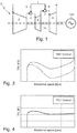
Figure 1 is a schematic view of a gas turbine assembly according to one embodiment of the present invention; -
Figure 2 is a partially sectioned, perspective view of the gas turbine assembly inFigure 1 ; -
Figure 3 is a graph showing the flame temperature (TFL) inside the first combustor of the gas turbine assembly versus rotational speed of the gas turbine assembly, during a start-up phase performed according to a conventional fixed-TAT1 schedule and with the gas turbine assembly in two different engine thermal states; whereas -
Figure 4 is a graph showing the flame temperature (TFL) inside the first combustor of the gas turbine assembly versus rotational speed of the gas turbine assembly, during a start-up phase performed according to the present invention and with the gas turbine assembly in the same two different engine thermal states shown inFigure 2 ; whereas -
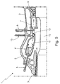
Figure 5 is a sectioned view of a portion of a gas turbine assembly operating according to an alternative embodiment of the present invention. - With reference to
Figures 1 and2 ,referral number 1 indicates as a whole a gas turbine assembly with sequential combustion which is preferably particularly adapted to drive into rotation a traditionalelectric generator 100. - The
gas turbine assembly 1 basically comprises, in succession along a main tubular casing 2: a preferably multi-stage,compressor 3 in which compression of the outside air occurs for producing a flow of compressed air; afirst combustor 4 which is located downstream ofcompressor 3 and in which combustion of a mixture of the compressed air arriving fromcompressor 3 and fuel arriving from a firstfuel supply line 5 occurs for producing a flow of hot gasses; a high-pressure turbine 6 which is located downstream ofcombustor 4 and in which a partial expansion of the hot gasses arriving fromcombustor 4 occurs; asecond combustor 7 which is located downstream ofturbine 6 and in which combustion of a mixture of the hot gasses arriving fromturbine 6 and fuel arriving from a secondfuel supply line 8 occurs for producing a second flow of hot gasses; and finally a preferably multi-stage, low-pressure turbine 9 which is located downstream ofcombustor 7 and in which a complete expansion of the hot gasses arriving fromcombustor 7 occurs before said hot gasses leave thegas turbine assembly 1. - The
first combustor 4 and thesecond combustor 7 define a sequential combustor. Preferably eachcombustor gas turbine assembly 1 moreover comprises a combustion chamber and a fuel burner located at inlet of said combustion chamber. - In the example shown,
combustors gas turbine assembly 1 are can-type combustors. However in adifferent embodiment combustors 5 and/or 7 could be cannular-type combustors or annular-type combustors. - Overall structure of
gas turbine assembly 1 is widely known per se, thus no further explanations are required. - General operation of
gas turbine assembly 1 is similar to that of any other gas turbine assembly with sequential combustion. - During stable full- or partial-load operations, fuel is conveniently supplied in known manner to combustor/
s 4 and/or 7 so that current power output continuously matches the electric-generator power demand. - Instead, on start-up of
gas turbine assembly 1, rather than controlling the fuel flow-rate in fuel supply line/s 5 and/or 8 according to a predetermined fixed-TAT1 schedule (i.e. on a predetermined schedule based on a given constant value of the gas temperature at the outlet of turbine 6), the fuel flow-rate in fuel supply line/s 5 and/or 8 is timely controlled according to the flame temperature inside thecombustion chamber 11 ofcombustor 4, hereinafter referred to as TFL1. - More in detail, the fuel flow-rate in fuel supply line/
s 5 and/or 8 is preferably controlled according to a predetermined TFL1 schedule which is preferably selected so as to maintain the TFL1 value (i.e. the flame temperature inside thecombustion chamber 11 of combustor 4) substantially constant during start-up phase. - However, since direct measurement of TFL1 (i.e. the flame temperature inside the
combustion chamber 11 of combustor 4) is normally not available, an estimate of TFL1 parameter is calculated on the basis of real-time measurement of several engine parameters ofgas turbine assembly 1. - Preferably these engine parameters are: the gas temperature at inlet of
compressor 3, hereinafter referred to as Tk1; the gas temperature at outlet ofcompressor 3, hereinafter referred to as Tk2; the gas temperature at the outlet ofturbine 6 or TAT1; the gas pressure at outlet ofcompressor 3, hereinafter referred to as Pk2; the gas pressure insidecombustor 4, hereinafter referred to as PEV; the gas pressure inside ofcombustor 7, hereinafter referred to as PSEV; and the rotational speed of theengine shaft 10 ofgas turbine assembly 1. - Therefore, the aforesaid TFL1 schedule is preferably selected/determined on the basis of the current values of a plurality of measured engine parameters (Tk1, Tk2, TAT1, Pk2, PEV, PSEV, etc.).
- Preferably, the TFL1 schedule moreover includes a sequence of target values for the gas temperature at the outlet of
turbine 6, hereinafter referred to as TAT1cmd, that are calculated on the basis of the current values of said plurality of engine parameters (Tk1, Tk2, TAT1, Pk2, PEV, PSEV, etc.), and according to a mathematical model describing the relations between TFL1 (i.e. the flame temperature inside thecombustion chamber 11 of combustor - More in detail, during start-up of
gas turbine assembly 1, the fuel flow-rate in fuel supply line/s 5 and/or 8 is preferably timely controlled so that the measured TAT1 parameter (i.e. the gas temperature measured at the outlet of turbine 6) matches a sequence of target values TAT1cmd resulting from the following equations:


- For what above, the method of controlling the
gas turbine assembly 1 during start-up preferably basically comprises the step of controlling the fuel mass flow-rate supplied tocombustor 4 and/orcombustor 7 on the basis of a predetermined TFL1 schedule, which is preferably adapted to maintain the flame temperature inside thecombustor chamber 11 ofcombustor 4, i.e. the TFL1 parameter, substantially constant during start-up. - More in detail, the method of controlling the
gas turbine assembly 1 preferably includes the steps of: - measuring a plurality of engine parameters (Tk1, Tk2, TAT1, Pk2, PEV, PSEV, etc.) of
gas turbine assembly 1; - selecting/determining the appropriate TFL1 schedule on the basis of the current values of said plurality of engine parameters (Tk1, Tk2, TAT1, Pk2, PEV, PSEV, etc.); and
- controlling the fuel mass flow-rate supplied to
combustor 4 and/or tocombustor 7 according to said TFL1 schedule. - Moreover said TFL1 schedule preferably includes a sequence of TATlcmd values (i.e. a sequence of target values for the gas temperature measured at the outlet of turbine 6), and the method of controlling the
gas turbine assembly 1 includes the steps of: - repetitively measuring the TAT1 values (i.e. the gas temperature at the outlet of turbine 6); and
- controlling the fuel mass flow-rate supplied to
combustor 4 and/orcombustor 7 so that the current TAT1 values timely matches said sequence of TATlcmd values. - The advantages resulting from the aforesaid method of controlling the
gas turbine assembly 1 are large in number. - Firstly, this method minimizes the flame instabilities inside the
combustion chamber 11 ofcombustor 4 during start-up ofgas turbine assembly 1, thus significantly reducing lean blowout phenomena and/or pressure pulsations. - Moreover, with reference to
Figures 2 and3 , the TFL1 schedule takes into consideration the current thermal state of the engine, thus optimizing the start-up phase of thegas turbine assembly 1 in all engine operating conditions. - Last, but not least, the aforesaid method allows to significantly reduce pollutant emissions during start-up phase of
gas turbine assembly 1. - Clearly, changes may be made to the
gas turbine assembly 1 and/or to the method of controlling thegas turbine assembly 1 without, however, departing from the scope of the present invention. - For example, according to the alternative embodiment shown in
Figure 5 , thegas turbine assembly 1 lacks the high-pressure turbine 6, and the flow of hot gasses coming out fromcombustor 4 flows through an intermediate hot-gas channel 12 directly intocombustor 7. - Preferably dilution air is moreover injected into the hot-
gas channel 12 by means of anair supply line 13. - Also in this embodiment, the fuel flow-rate in fuel supply line/
s 5 and/or 8 is timely controlled according to the flame temperature inside thecombustion chamber 11 ofcombustor 4 or TFL1. - More in detail, the fuel flow-rate in fuel supply line/
s 5 and/or 8 is preferably controlled according to a predetermined TFL1 schedule which is preferably selected so as to maintain the TFL1 value (i.e. the flame temperature inside thecombustion chamber 11 of combustor 4) substantially constant during start-up phase. - Also in this embodiment, since direct measurement of TFL1 (i.e. the flame temperature inside the
combustion chamber 11 of combustor 4) is actually impossible, an estimate of TFL1 parameter is calculated on the basis of real-time measurement of several engine parameters ofgas turbine assembly 1. - Preferably these engine parameters are: the gas temperature at inlet of
compressor 3, hereinafter referred to as Tk1; the gas temperature at outlet ofcompressor 3 and at inlet ofcombustor 4, hereinafter referred to as Tk2 or TEV1; the gas temperature at inlet ofcombustor 7, hereinafter referred to as TSEV1; the gas pressure at outlet ofcompressor 3 or Pk2 (also corresponding to the gas pressure at inlet of combustor 4); the gas pressure insidecombustor 4 or PEV; the gas pressure inside ofcombustor 7 or PSEV; and the rotational speed of theengine shaft 10 ofgas turbine assembly 1. - Also in this case, therefore, the TFL1 schedule is preferably selected/determined on the basis of the current values of a plurality of measured engine parameters (Tk1, Tk2, TSEV1, Pk2, PEV, PSEV, etc.).
- Preferably, the TFL1 schedule moreover includes a sequence of target values for the gas temperature at inlet of
combustor 7, i.e. along hot-gas channel 12, that are calculated on the basis of the current values of said plurality of engine parameters (Tk1, Tk2, TSEV1, Pk2, PEV, PSEV, etc.), and according to a mathematical model describing the relations between TFL1 (i.e. the flame temperature inside thecombustion chamber 11 of combustor 4) and said engine parameters. - According to a second non-shown alternative embodiment, the
gas turbine assembly 1 may have more than two combustors. - In other words, the
gas turbine assembly 1 may optionally comprise also a third combustor which is located downstream ofturbine 9 and in which combustion of a mixture of the hot gasses arriving fromturbine 9 and fuel arriving from a third fuel supply line occurs for producing a further flow of hot gasses; and a preferably multi-stage, second low-pressure turbine which is located downstream of the third combustor and in which a complete expansion of the hot gasses arriving from third combustor occurs before said hot gasses leave thegas turbine assembly 1. - Finally according to a non-shown less sophisticated embodiment, the
gas turbine assembly 1 lacks both the high-pressure turbine 6 and thesecond combustor 7. - In this embodiment, rather than controlling the fuel flow-rate in fuel supply line/
s 5 and/or 8 according to a predetermined fixed-TEV2 schedule (i.e. on a predetermined schedule based on a given constant value of the gas temperature at outlet ofcombustor 4, again the fuel flow-rate infuel supply line 5 is timely controlled according to the flame temperature inside thecombustion chamber 11 ofcombustor 4 or TFL1. - More in detail, the fuel flow-rate in
fuel supply line 5 is preferably controlled according to a predetermined TFL1 schedule which is preferably selected so as to maintain the TFL1 value (i.e. the flame temperature inside thecombustion chamber 11 of combustor 4) substantially constant during start-up phase.
Claims (9)
- A method for controlling a gas turbine assembly (1) comprising: a compressor (2) in which compression of the outside air occurs for producing a flow of compressed air; a sequential combustor including a first combustor (4), in which combustion of a mixture of fuel and compressed air arriving from said compressor (2) occurs for producing a flow of hot gasses, and a second combustor (7) which is located downstream of said first combustor (4) and in which combustion of a mixture of fuel and hot gasses arriving from said first combustor (4) occurs;
the method being characterized by comprising, on a start-up transient operating phase of the gas turbine assembly (1), the step of controlling the fuel mass flow-rate supplied to said first combustor (4) on the basis of the flame temperature (TFL1) inside said first combustor (4). - Method according to Claim 1, characterized in that the fuel mass flow-rate supplied to said first combustor (4) is controlled according to a predetermined TFL1 schedule.
- Method according to Claim 2, characterized in that said TFL1 schedule is adapted to maintain the flame temperature (TFL1) inside the first combustor (4) substantially constant during the start-up transient operating phase.
- Method according to Claim 2 or 3, characterized in that said TFL1 schedule is determined on the basis of the values of a plurality of engine parameters (Tk1, Tk2, TAT1, TSEV1, Pk2, PEV, PSEV, etc.) of said gas turbine assembly (1).
- Method according to Claim 4, characterized in that said gas turbine assembly (1) additionally comprises an intermediate turbine (5) which is interposed between said first combustor (4) and said second combustor (7), and in which a partial expansion of the hot gasses arriving from said first combustor (4) and directed to said second combustor (7) occurs.
- Method according to Claim 3, 4 or 5, characterized by comprising the steps of: measuring said plurality of engine parameters (Tk1, Tk2, TAT1, Pk2, PEV, PSEV, etc.) of the gas turbine assembly (1); selecting/determining the appropriate TFL1 schedule on the basis of the current values of said plurality of engine parameters (Tk1, Tk2, TAT1, Pk2, PEV, PSEV, etc.); and controlling the fuel mass flow-rate supplied to said first (4) and/or to said second combustor (7) on the basis of the said TFL1 schedule.
- Method according to Claim 5 or 6, characterized in that said TFL1 schedule includes a sequence of target values (TAT1cmd) for the gas temperature measured at the outlet of the intermediate turbine (5); said target values (TAT1cmd) being calculated on the basis of the current values of said engine parameters (Tk1, Tk2, TAT1, Pk2, PEV, PSEV, etc.) of said gas turbine assembly (1), and according to a mathematical model describing the relations between the flame temperature (TFL1) inside the first combustor (4) and said engine parameters (Tk1, Tk2, TAT1, Pk2, PEV, PSEV, etc.).
- Method according to Claim 7, characterized by comprising the steps of repetitively measuring the gas temperature (TAT1) at the outlet of said intermediate turbine (5); and the step of controlling the fuel mass flow-rate supplied to said first combustor (4) and/or said second combustor (7) so that the gas temperature (TAT1) measured at the outlet of the intermediate turbine (5) matches said sequence of target values (TAT1cmd).
- Method according to any one of Claims 5 to 8, characterized in that said plurality of engine parameters includes the gas temperature at the inlet of said compressor (Tk1), and/or the gas temperature at the outlet of said compressor (Tk2), and/or the gas temperature at the outlet of said intermediate turbine (TAT1), and/or the gas pressure at the outlet of said compressor (Pk2), and/or the gas pressure inside said first combustor (PEV), and/or the gas pressure inside of said second combustor (PSEV), and/or the rotational speed of the engine shaft (9) of gas turbine assembly (1).
Priority Applications (4)
| Application Number | Priority Date | Filing Date | Title |
|---|---|---|---|
| EP16178756.9A EP3267107B1 (en) | 2016-07-08 | 2016-07-08 | Method of controlling a gas turbine assembly |
| US15/642,061 US20180010528A1 (en) | 2016-07-08 | 2017-07-05 | Method of controlling a gas turbine assembly |
| JP2017133716A JP2018003848A (en) | 2016-07-08 | 2017-07-07 | Method for controlling gas turbine assembly |
| CN201710551844.9A CN107587944B (en) | 2016-07-08 | 2017-07-07 | Method of controlling a gas turbine assembly |
Applications Claiming Priority (1)
| Application Number | Priority Date | Filing Date | Title |
|---|---|---|---|
| EP16178756.9A EP3267107B1 (en) | 2016-07-08 | 2016-07-08 | Method of controlling a gas turbine assembly |
Publications (2)
| Publication Number | Publication Date |
|---|---|
| EP3267107A1 true EP3267107A1 (en) | 2018-01-10 |
| EP3267107B1 EP3267107B1 (en) | 2021-03-17 |
Family
ID=56464029
Family Applications (1)
| Application Number | Title | Priority Date | Filing Date |
|---|---|---|---|
| EP16178756.9A Active EP3267107B1 (en) | 2016-07-08 | 2016-07-08 | Method of controlling a gas turbine assembly |
Country Status (4)
| Country | Link |
|---|---|
| US (1) | US20180010528A1 (en) |
| EP (1) | EP3267107B1 (en) |
| JP (1) | JP2018003848A (en) |
| CN (1) | CN107587944B (en) |
Cited By (4)
| Publication number | Priority date | Publication date | Assignee | Title |
|---|---|---|---|---|
| EP3578762A1 (en) * | 2018-06-08 | 2019-12-11 | General Electric Technology GmbH | Method for determining an outlet temperature of an upstream combustion stage in a gas turbine engine having at least two serially arranged combustion stages |
| EP3686493A1 (en) * | 2019-01-23 | 2020-07-29 | General Electric Company | Gas turbine load/unload path control |
| US11156164B2 (en) | 2019-05-21 | 2021-10-26 | General Electric Company | System and method for high frequency accoustic dampers with caps |
| US11174792B2 (en) | 2019-05-21 | 2021-11-16 | General Electric Company | System and method for high frequency acoustic dampers with baffles |
Families Citing this family (6)
| Publication number | Priority date | Publication date | Assignee | Title |
|---|---|---|---|---|
| US20190002117A1 (en) * | 2017-06-30 | 2019-01-03 | General Electric Company | Propulsion system for an aircraft |
| EP3530912A1 (en) | 2018-02-23 | 2019-08-28 | Siemens Aktiengesellschaft | Controller and method |
| EP3530913A1 (en) * | 2018-02-23 | 2019-08-28 | Siemens Aktiengesellschaft | Controller and method |
| EP3945244B1 (en) * | 2020-07-27 | 2024-10-02 | Ansaldo Energia Switzerland AG | Method for manufacturing a controller and combustion system |
| CN112901343A (en) * | 2021-02-01 | 2021-06-04 | 中国航发沈阳发动机研究所 | Ground gas turbine with low pollutant emission |
| US11578869B2 (en) * | 2021-05-20 | 2023-02-14 | General Electric Company | Active boundary layer control in diffuser |
Citations (6)
| Publication number | Priority date | Publication date | Assignee | Title |
|---|---|---|---|---|
| EP0694740A2 (en) * | 1994-07-25 | 1996-01-31 | Abb Research Ltd. | Combustion chamber |
| US20050188702A1 (en) * | 2002-05-01 | 2005-09-01 | Siemens Westinghouse Power Corporation | Non-catalytic combustor for reducing nox emissions |
| EP2287456A1 (en) * | 2009-08-17 | 2011-02-23 | Alstom Technology Ltd | Gas turbine and method for operating a gas turbine |
| EP2290206A1 (en) * | 2009-08-28 | 2011-03-02 | Alstom Technology Ltd | Method for operating a gas turbine plant with reduced NOx emissions |
| US20120073305A1 (en) * | 2010-09-24 | 2012-03-29 | Alstom Technology Ltd | Combustion chamber and method for operating a combustion chamber |
| EP2581583A1 (en) * | 2011-10-14 | 2013-04-17 | Alstom Technology Ltd | Method for operating a gas turbine |
Family Cites Families (5)
| Publication number | Priority date | Publication date | Assignee | Title |
|---|---|---|---|---|
| US5487266A (en) * | 1992-05-05 | 1996-01-30 | General Electric Company | Combustion control for producing low NOx emissions through use of flame spectroscopy |
| JP2960848B2 (en) * | 1994-01-19 | 1999-10-12 | 三菱重工業株式会社 | gas turbine |
| US6865889B2 (en) * | 2002-02-01 | 2005-03-15 | General Electric Company | Method and apparatus to decrease combustor emissions |
| EP2840245A1 (en) * | 2013-08-20 | 2015-02-25 | Alstom Technology Ltd | Method for controlling a gas turbine group |
| US9665077B2 (en) * | 2013-12-18 | 2017-05-30 | General Electric Company | Gas turbine firing temperature control system and method |
-
2016
- 2016-07-08 EP EP16178756.9A patent/EP3267107B1/en active Active
-
2017
- 2017-07-05 US US15/642,061 patent/US20180010528A1/en not_active Abandoned
- 2017-07-07 CN CN201710551844.9A patent/CN107587944B/en active Active
- 2017-07-07 JP JP2017133716A patent/JP2018003848A/en active Pending
Patent Citations (6)
| Publication number | Priority date | Publication date | Assignee | Title |
|---|---|---|---|---|
| EP0694740A2 (en) * | 1994-07-25 | 1996-01-31 | Abb Research Ltd. | Combustion chamber |
| US20050188702A1 (en) * | 2002-05-01 | 2005-09-01 | Siemens Westinghouse Power Corporation | Non-catalytic combustor for reducing nox emissions |
| EP2287456A1 (en) * | 2009-08-17 | 2011-02-23 | Alstom Technology Ltd | Gas turbine and method for operating a gas turbine |
| EP2290206A1 (en) * | 2009-08-28 | 2011-03-02 | Alstom Technology Ltd | Method for operating a gas turbine plant with reduced NOx emissions |
| US20120073305A1 (en) * | 2010-09-24 | 2012-03-29 | Alstom Technology Ltd | Combustion chamber and method for operating a combustion chamber |
| EP2581583A1 (en) * | 2011-10-14 | 2013-04-17 | Alstom Technology Ltd | Method for operating a gas turbine |
Cited By (6)
| Publication number | Priority date | Publication date | Assignee | Title |
|---|---|---|---|---|
| EP3578762A1 (en) * | 2018-06-08 | 2019-12-11 | General Electric Technology GmbH | Method for determining an outlet temperature of an upstream combustion stage in a gas turbine engine having at least two serially arranged combustion stages |
| EP3686493A1 (en) * | 2019-01-23 | 2020-07-29 | General Electric Company | Gas turbine load/unload path control |
| US11384940B2 (en) | 2019-01-23 | 2022-07-12 | General Electric Company | Gas turbine load/unload path control |
| US11506389B2 (en) | 2019-01-23 | 2022-11-22 | General Electric Company | Gas turbine load/unload path control |
| US11156164B2 (en) | 2019-05-21 | 2021-10-26 | General Electric Company | System and method for high frequency accoustic dampers with caps |
| US11174792B2 (en) | 2019-05-21 | 2021-11-16 | General Electric Company | System and method for high frequency acoustic dampers with baffles |
Also Published As
| Publication number | Publication date |
|---|---|
| CN107587944B (en) | 2021-10-22 |
| US20180010528A1 (en) | 2018-01-11 |
| EP3267107B1 (en) | 2021-03-17 |
| CN107587944A (en) | 2018-01-16 |
| JP2018003848A (en) | 2018-01-11 |
Similar Documents
| Publication | Publication Date | Title |
|---|---|---|
| EP3267107B1 (en) | Method of controlling a gas turbine assembly | |
| EP2504546B1 (en) | Exhaust temperature based mode control method for gas turbine and gas turbine | |
| EP3521593B1 (en) | Gas turbine combustor, gas turbine, and control method for gas turbine combustor | |
| CN103291464B (en) | The gas-turbine unit of sensor-based pursuit performance controls | |
| US10208678B2 (en) | Gas turbine combustion control device and combustion control method and program therefor | |
| US7823388B2 (en) | Gas turbine engine control system | |
| US20040011056A1 (en) | Design and control strategy for catalytic combustion system with a wide operating range | |
| US20120279230A1 (en) | Exhaust temperature based threshold for control method and turbine | |
| EP0765998A2 (en) | Turbine engine control system | |
| US20160153365A1 (en) | Method of Operation of a Gas Turbine Engine | |
| US20060042258A1 (en) | Method of controlling a power generation system | |
| US20120017600A1 (en) | Combustor Control Method and Combustor Controller | |
| US7681401B2 (en) | Methods and systems for operating a gas turbine | |
| EP3056715A1 (en) | Systems and methods for controlling an inlet air temperature of an intercooleld gas turbine engine | |
| US20130219910A1 (en) | Exhaust temperature based threshold for control method and turbine | |
| US9249738B2 (en) | Method for automatic closed-loop control of one or more combustion temperatures in a gas turbine installation and method for determination of the water content in the working fluid of a gas turbine installation | |
| US11208959B2 (en) | System and method for flexible fuel usage for gas turbines | |
| JP5501870B2 (en) | gas turbine | |
| CN105927392B (en) | Method for controlling operation of a gas turbine with sequential combustion | |
| CN104421002B (en) | Method for controlling gas turbine group | |
| EP3447268B1 (en) | Engine control system | |
| US20170089268A1 (en) | Gas turbine combustion control device and combustion control method and program therefor | |
| US12473860B2 (en) | Gas turbine engines and methods of controlling formation of condensates |
Legal Events
| Date | Code | Title | Description |
|---|---|---|---|
| PUAI | Public reference made under article 153(3) epc to a published international application that has entered the european phase |
Free format text: ORIGINAL CODE: 0009012 |
|
| STAA | Information on the status of an ep patent application or granted ep patent |
Free format text: STATUS: THE APPLICATION HAS BEEN PUBLISHED |
|
| AK | Designated contracting states |
Kind code of ref document: A1 Designated state(s): AL AT BE BG CH CY CZ DE DK EE ES FI FR GB GR HR HU IE IS IT LI LT LU LV MC MK MT NL NO PL PT RO RS SE SI SK SM TR |
|
| AX | Request for extension of the european patent |
Extension state: BA ME |
|
| STAA | Information on the status of an ep patent application or granted ep patent |
Free format text: STATUS: REQUEST FOR EXAMINATION WAS MADE |
|
| 17P | Request for examination filed |
Effective date: 20180709 |
|
| RBV | Designated contracting states (corrected) |
Designated state(s): AL AT BE BG CH CY CZ DE DK EE ES FI FR GB GR HR HU IE IS IT LI LT LU LV MC MK MT NL NO PL PT RO RS SE SI SK SM TR |
|
| STAA | Information on the status of an ep patent application or granted ep patent |
Free format text: STATUS: EXAMINATION IS IN PROGRESS |
|
| 17Q | First examination report despatched |
Effective date: 20200218 |
|
| GRAP | Despatch of communication of intention to grant a patent |
Free format text: ORIGINAL CODE: EPIDOSNIGR1 |
|
| STAA | Information on the status of an ep patent application or granted ep patent |
Free format text: STATUS: GRANT OF PATENT IS INTENDED |
|
| INTG | Intention to grant announced |
Effective date: 20201007 |
|
| GRAS | Grant fee paid |
Free format text: ORIGINAL CODE: EPIDOSNIGR3 |
|
| GRAA | (expected) grant |
Free format text: ORIGINAL CODE: 0009210 |
|
| STAA | Information on the status of an ep patent application or granted ep patent |
Free format text: STATUS: THE PATENT HAS BEEN GRANTED |
|
| AK | Designated contracting states |
Kind code of ref document: B1 Designated state(s): AL AT BE BG CH CY CZ DE DK EE ES FI FR GB GR HR HU IE IS IT LI LT LU LV MC MK MT NL NO PL PT RO RS SE SI SK SM TR |
|
| REG | Reference to a national code |
Ref country code: GB Ref legal event code: FG4D |
|
| REG | Reference to a national code |
Ref country code: CH Ref legal event code: EP |
|
| REG | Reference to a national code |
Ref country code: DE Ref legal event code: R096 Ref document number: 602016054330 Country of ref document: DE |
|
| REG | Reference to a national code |
Ref country code: IE Ref legal event code: FG4D |
|
| REG | Reference to a national code |
Ref country code: AT Ref legal event code: REF Ref document number: 1372586 Country of ref document: AT Kind code of ref document: T Effective date: 20210415 |
|
| REG | Reference to a national code |
Ref country code: LT Ref legal event code: MG9D |
|
| PG25 | Lapsed in a contracting state [announced via postgrant information from national office to epo] |
Ref country code: NO Free format text: LAPSE BECAUSE OF FAILURE TO SUBMIT A TRANSLATION OF THE DESCRIPTION OR TO PAY THE FEE WITHIN THE PRESCRIBED TIME-LIMIT Effective date: 20210617 Ref country code: BG Free format text: LAPSE BECAUSE OF FAILURE TO SUBMIT A TRANSLATION OF THE DESCRIPTION OR TO PAY THE FEE WITHIN THE PRESCRIBED TIME-LIMIT Effective date: 20210617 Ref country code: HR Free format text: LAPSE BECAUSE OF FAILURE TO SUBMIT A TRANSLATION OF THE DESCRIPTION OR TO PAY THE FEE WITHIN THE PRESCRIBED TIME-LIMIT Effective date: 20210317 Ref country code: GR Free format text: LAPSE BECAUSE OF FAILURE TO SUBMIT A TRANSLATION OF THE DESCRIPTION OR TO PAY THE FEE WITHIN THE PRESCRIBED TIME-LIMIT Effective date: 20210618 Ref country code: FI Free format text: LAPSE BECAUSE OF FAILURE TO SUBMIT A TRANSLATION OF THE DESCRIPTION OR TO PAY THE FEE WITHIN THE PRESCRIBED TIME-LIMIT Effective date: 20210317 |
|
| REG | Reference to a national code |
Ref country code: AT Ref legal event code: MK05 Ref document number: 1372586 Country of ref document: AT Kind code of ref document: T Effective date: 20210317 |
|
| REG | Reference to a national code |
Ref country code: NL Ref legal event code: MP Effective date: 20210317 |
|
| PG25 | Lapsed in a contracting state [announced via postgrant information from national office to epo] |
Ref country code: SE Free format text: LAPSE BECAUSE OF FAILURE TO SUBMIT A TRANSLATION OF THE DESCRIPTION OR TO PAY THE FEE WITHIN THE PRESCRIBED TIME-LIMIT Effective date: 20210317 Ref country code: LV Free format text: LAPSE BECAUSE OF FAILURE TO SUBMIT A TRANSLATION OF THE DESCRIPTION OR TO PAY THE FEE WITHIN THE PRESCRIBED TIME-LIMIT Effective date: 20210317 Ref country code: RS Free format text: LAPSE BECAUSE OF FAILURE TO SUBMIT A TRANSLATION OF THE DESCRIPTION OR TO PAY THE FEE WITHIN THE PRESCRIBED TIME-LIMIT Effective date: 20210317 |
|
| PG25 | Lapsed in a contracting state [announced via postgrant information from national office to epo] |
Ref country code: NL Free format text: LAPSE BECAUSE OF FAILURE TO SUBMIT A TRANSLATION OF THE DESCRIPTION OR TO PAY THE FEE WITHIN THE PRESCRIBED TIME-LIMIT Effective date: 20210317 |
|
| PG25 | Lapsed in a contracting state [announced via postgrant information from national office to epo] |
Ref country code: CZ Free format text: LAPSE BECAUSE OF FAILURE TO SUBMIT A TRANSLATION OF THE DESCRIPTION OR TO PAY THE FEE WITHIN THE PRESCRIBED TIME-LIMIT Effective date: 20210317 Ref country code: EE Free format text: LAPSE BECAUSE OF FAILURE TO SUBMIT A TRANSLATION OF THE DESCRIPTION OR TO PAY THE FEE WITHIN THE PRESCRIBED TIME-LIMIT Effective date: 20210317 Ref country code: LT Free format text: LAPSE BECAUSE OF FAILURE TO SUBMIT A TRANSLATION OF THE DESCRIPTION OR TO PAY THE FEE WITHIN THE PRESCRIBED TIME-LIMIT Effective date: 20210317 Ref country code: AT Free format text: LAPSE BECAUSE OF FAILURE TO SUBMIT A TRANSLATION OF THE DESCRIPTION OR TO PAY THE FEE WITHIN THE PRESCRIBED TIME-LIMIT Effective date: 20210317 Ref country code: SM Free format text: LAPSE BECAUSE OF FAILURE TO SUBMIT A TRANSLATION OF THE DESCRIPTION OR TO PAY THE FEE WITHIN THE PRESCRIBED TIME-LIMIT Effective date: 20210317 |
|
| PG25 | Lapsed in a contracting state [announced via postgrant information from national office to epo] |
Ref country code: SK Free format text: LAPSE BECAUSE OF FAILURE TO SUBMIT A TRANSLATION OF THE DESCRIPTION OR TO PAY THE FEE WITHIN THE PRESCRIBED TIME-LIMIT Effective date: 20210317 Ref country code: RO Free format text: LAPSE BECAUSE OF FAILURE TO SUBMIT A TRANSLATION OF THE DESCRIPTION OR TO PAY THE FEE WITHIN THE PRESCRIBED TIME-LIMIT Effective date: 20210317 Ref country code: PL Free format text: LAPSE BECAUSE OF FAILURE TO SUBMIT A TRANSLATION OF THE DESCRIPTION OR TO PAY THE FEE WITHIN THE PRESCRIBED TIME-LIMIT Effective date: 20210317 Ref country code: PT Free format text: LAPSE BECAUSE OF FAILURE TO SUBMIT A TRANSLATION OF THE DESCRIPTION OR TO PAY THE FEE WITHIN THE PRESCRIBED TIME-LIMIT Effective date: 20210719 Ref country code: IS Free format text: LAPSE BECAUSE OF FAILURE TO SUBMIT A TRANSLATION OF THE DESCRIPTION OR TO PAY THE FEE WITHIN THE PRESCRIBED TIME-LIMIT Effective date: 20210717 |
|
| REG | Reference to a national code |
Ref country code: DE Ref legal event code: R097 Ref document number: 602016054330 Country of ref document: DE |
|
| PLBE | No opposition filed within time limit |
Free format text: ORIGINAL CODE: 0009261 |
|
| STAA | Information on the status of an ep patent application or granted ep patent |
Free format text: STATUS: NO OPPOSITION FILED WITHIN TIME LIMIT |
|
| PG25 | Lapsed in a contracting state [announced via postgrant information from national office to epo] |
Ref country code: DK Free format text: LAPSE BECAUSE OF FAILURE TO SUBMIT A TRANSLATION OF THE DESCRIPTION OR TO PAY THE FEE WITHIN THE PRESCRIBED TIME-LIMIT Effective date: 20210317 Ref country code: AL Free format text: LAPSE BECAUSE OF FAILURE TO SUBMIT A TRANSLATION OF THE DESCRIPTION OR TO PAY THE FEE WITHIN THE PRESCRIBED TIME-LIMIT Effective date: 20210317 Ref country code: ES Free format text: LAPSE BECAUSE OF FAILURE TO SUBMIT A TRANSLATION OF THE DESCRIPTION OR TO PAY THE FEE WITHIN THE PRESCRIBED TIME-LIMIT Effective date: 20210317 |
|
| 26N | No opposition filed |
Effective date: 20211220 |
|
| PG25 | Lapsed in a contracting state [announced via postgrant information from national office to epo] |
Ref country code: SI Free format text: LAPSE BECAUSE OF FAILURE TO SUBMIT A TRANSLATION OF THE DESCRIPTION OR TO PAY THE FEE WITHIN THE PRESCRIBED TIME-LIMIT Effective date: 20210317 |
|
| REG | Reference to a national code |
Ref country code: CH Ref legal event code: PL |
|
| GBPC | Gb: european patent ceased through non-payment of renewal fee |
Effective date: 20210708 |
|
| PG25 | Lapsed in a contracting state [announced via postgrant information from national office to epo] |
Ref country code: MC Free format text: LAPSE BECAUSE OF FAILURE TO SUBMIT A TRANSLATION OF THE DESCRIPTION OR TO PAY THE FEE WITHIN THE PRESCRIBED TIME-LIMIT Effective date: 20210317 |
|
| REG | Reference to a national code |
Ref country code: BE Ref legal event code: MM Effective date: 20210731 |
|
| PG25 | Lapsed in a contracting state [announced via postgrant information from national office to epo] |
Ref country code: LI Free format text: LAPSE BECAUSE OF NON-PAYMENT OF DUE FEES Effective date: 20210731 Ref country code: IT Free format text: LAPSE BECAUSE OF FAILURE TO SUBMIT A TRANSLATION OF THE DESCRIPTION OR TO PAY THE FEE WITHIN THE PRESCRIBED TIME-LIMIT Effective date: 20210317 Ref country code: GB Free format text: LAPSE BECAUSE OF NON-PAYMENT OF DUE FEES Effective date: 20210708 Ref country code: CH Free format text: LAPSE BECAUSE OF NON-PAYMENT OF DUE FEES Effective date: 20210731 |
|
| PG25 | Lapsed in a contracting state [announced via postgrant information from national office to epo] |
Ref country code: IS Free format text: LAPSE BECAUSE OF FAILURE TO SUBMIT A TRANSLATION OF THE DESCRIPTION OR TO PAY THE FEE WITHIN THE PRESCRIBED TIME-LIMIT Effective date: 20210717 Ref country code: LU Free format text: LAPSE BECAUSE OF NON-PAYMENT OF DUE FEES Effective date: 20210708 Ref country code: FR Free format text: LAPSE BECAUSE OF NON-PAYMENT OF DUE FEES Effective date: 20210731 |
|
| PG25 | Lapsed in a contracting state [announced via postgrant information from national office to epo] |
Ref country code: IE Free format text: LAPSE BECAUSE OF NON-PAYMENT OF DUE FEES Effective date: 20210708 Ref country code: BE Free format text: LAPSE BECAUSE OF NON-PAYMENT OF DUE FEES Effective date: 20210731 |
|
| PG25 | Lapsed in a contracting state [announced via postgrant information from national office to epo] |
Ref country code: HU Free format text: LAPSE BECAUSE OF FAILURE TO SUBMIT A TRANSLATION OF THE DESCRIPTION OR TO PAY THE FEE WITHIN THE PRESCRIBED TIME-LIMIT; INVALID AB INITIO Effective date: 20160708 |
|
| PG25 | Lapsed in a contracting state [announced via postgrant information from national office to epo] |
Ref country code: CY Free format text: LAPSE BECAUSE OF FAILURE TO SUBMIT A TRANSLATION OF THE DESCRIPTION OR TO PAY THE FEE WITHIN THE PRESCRIBED TIME-LIMIT Effective date: 20210317 |
|
| PG25 | Lapsed in a contracting state [announced via postgrant information from national office to epo] |
Ref country code: MK Free format text: LAPSE BECAUSE OF FAILURE TO SUBMIT A TRANSLATION OF THE DESCRIPTION OR TO PAY THE FEE WITHIN THE PRESCRIBED TIME-LIMIT Effective date: 20210317 |
|
| P01 | Opt-out of the competence of the unified patent court (upc) registered |
Effective date: 20240430 |
|
| PG25 | Lapsed in a contracting state [announced via postgrant information from national office to epo] |
Ref country code: TR Free format text: LAPSE BECAUSE OF FAILURE TO SUBMIT A TRANSLATION OF THE DESCRIPTION OR TO PAY THE FEE WITHIN THE PRESCRIBED TIME-LIMIT Effective date: 20210317 |
|
| PG25 | Lapsed in a contracting state [announced via postgrant information from national office to epo] |
Ref country code: MT Free format text: LAPSE BECAUSE OF FAILURE TO SUBMIT A TRANSLATION OF THE DESCRIPTION OR TO PAY THE FEE WITHIN THE PRESCRIBED TIME-LIMIT Effective date: 20210317 |
|
| PGFP | Annual fee paid to national office [announced via postgrant information from national office to epo] |
Ref country code: DE Payment date: 20250722 Year of fee payment: 10 |