EP3267075A1 - A geared gas turbine engine and a gearbox - Google Patents
A geared gas turbine engine and a gearbox Download PDFInfo
- Publication number
- EP3267075A1 EP3267075A1 EP17177060.5A EP17177060A EP3267075A1 EP 3267075 A1 EP3267075 A1 EP 3267075A1 EP 17177060 A EP17177060 A EP 17177060A EP 3267075 A1 EP3267075 A1 EP 3267075A1
- Authority
- EP
- European Patent Office
- Prior art keywords
- ring
- matrix composite
- gas turbine
- turbine engine
- reinforcing fibres
- Prior art date
- Legal status (The legal status is an assumption and is not a legal conclusion. Google has not performed a legal analysis and makes no representation as to the accuracy of the status listed.)
- Granted
Links
Images


Classifications
-
- F—MECHANICAL ENGINEERING; LIGHTING; HEATING; WEAPONS; BLASTING
- F02—COMBUSTION ENGINES; HOT-GAS OR COMBUSTION-PRODUCT ENGINE PLANTS
- F02C—GAS-TURBINE PLANTS; AIR INTAKES FOR JET-PROPULSION PLANTS; CONTROLLING FUEL SUPPLY IN AIR-BREATHING JET-PROPULSION PLANTS
- F02C7/00—Features, components parts, details or accessories, not provided for in, or of interest apart form groups F02C1/00 - F02C6/00; Air intakes for jet-propulsion plants
- F02C7/36—Power transmission arrangements between the different shafts of the gas turbine plant, or between the gas-turbine plant and the power user
-
- F—MECHANICAL ENGINEERING; LIGHTING; HEATING; WEAPONS; BLASTING
- F02—COMBUSTION ENGINES; HOT-GAS OR COMBUSTION-PRODUCT ENGINE PLANTS
- F02C—GAS-TURBINE PLANTS; AIR INTAKES FOR JET-PROPULSION PLANTS; CONTROLLING FUEL SUPPLY IN AIR-BREATHING JET-PROPULSION PLANTS
- F02C7/00—Features, components parts, details or accessories, not provided for in, or of interest apart form groups F02C1/00 - F02C6/00; Air intakes for jet-propulsion plants
- F02C7/32—Arrangement, mounting, or driving, of auxiliaries
-
- F—MECHANICAL ENGINEERING; LIGHTING; HEATING; WEAPONS; BLASTING
- F16—ENGINEERING ELEMENTS AND UNITS; GENERAL MEASURES FOR PRODUCING AND MAINTAINING EFFECTIVE FUNCTIONING OF MACHINES OR INSTALLATIONS; THERMAL INSULATION IN GENERAL
- F16H—GEARING
- F16H1/00—Toothed gearings for conveying rotary motion
- F16H1/02—Toothed gearings for conveying rotary motion without gears having orbital motion
-
- F—MECHANICAL ENGINEERING; LIGHTING; HEATING; WEAPONS; BLASTING
- F16—ENGINEERING ELEMENTS AND UNITS; GENERAL MEASURES FOR PRODUCING AND MAINTAINING EFFECTIVE FUNCTIONING OF MACHINES OR INSTALLATIONS; THERMAL INSULATION IN GENERAL
- F16H—GEARING
- F16H57/00—General details of gearing
- F16H57/08—General details of gearing of gearings with members having orbital motion
- F16H57/082—Planet carriers
-
- B—PERFORMING OPERATIONS; TRANSPORTING
- B64—AIRCRAFT; AVIATION; COSMONAUTICS
- B64D—EQUIPMENT FOR FITTING IN OR TO AIRCRAFT; FLIGHT SUITS; PARACHUTES; ARRANGEMENT OR MOUNTING OF POWER PLANTS OR PROPULSION TRANSMISSIONS IN AIRCRAFT
- B64D35/00—Transmitting power from power plants to propellers or rotors; Arrangements of transmissions
-
- F—MECHANICAL ENGINEERING; LIGHTING; HEATING; WEAPONS; BLASTING
- F05—INDEXING SCHEMES RELATING TO ENGINES OR PUMPS IN VARIOUS SUBCLASSES OF CLASSES F01-F04
- F05D—INDEXING SCHEME FOR ASPECTS RELATING TO NON-POSITIVE-DISPLACEMENT MACHINES OR ENGINES, GAS-TURBINES OR JET-PROPULSION PLANTS
- F05D2260/00—Function
- F05D2260/40—Transmission of power
- F05D2260/403—Transmission of power through the shape of the drive components
- F05D2260/4031—Transmission of power through the shape of the drive components as in toothed gearing
- F05D2260/40311—Transmission of power through the shape of the drive components as in toothed gearing of the epicyclical, planetary or differential type
-
- F—MECHANICAL ENGINEERING; LIGHTING; HEATING; WEAPONS; BLASTING
- F05—INDEXING SCHEMES RELATING TO ENGINES OR PUMPS IN VARIOUS SUBCLASSES OF CLASSES F01-F04
- F05D—INDEXING SCHEME FOR ASPECTS RELATING TO NON-POSITIVE-DISPLACEMENT MACHINES OR ENGINES, GAS-TURBINES OR JET-PROPULSION PLANTS
- F05D2260/00—Function
- F05D2260/50—Kinematic linkage, i.e. transmission of position
- F05D2260/53—Kinematic linkage, i.e. transmission of position using gears
-
- F—MECHANICAL ENGINEERING; LIGHTING; HEATING; WEAPONS; BLASTING
- F05—INDEXING SCHEMES RELATING TO ENGINES OR PUMPS IN VARIOUS SUBCLASSES OF CLASSES F01-F04
- F05D—INDEXING SCHEME FOR ASPECTS RELATING TO NON-POSITIVE-DISPLACEMENT MACHINES OR ENGINES, GAS-TURBINES OR JET-PROPULSION PLANTS
- F05D2300/00—Materials; Properties thereof
- F05D2300/60—Properties or characteristics given to material by treatment or manufacturing
- F05D2300/603—Composites; e.g. fibre-reinforced
-
- F—MECHANICAL ENGINEERING; LIGHTING; HEATING; WEAPONS; BLASTING
- F05—INDEXING SCHEMES RELATING TO ENGINES OR PUMPS IN VARIOUS SUBCLASSES OF CLASSES F01-F04
- F05D—INDEXING SCHEME FOR ASPECTS RELATING TO NON-POSITIVE-DISPLACEMENT MACHINES OR ENGINES, GAS-TURBINES OR JET-PROPULSION PLANTS
- F05D2300/00—Materials; Properties thereof
- F05D2300/60—Properties or characteristics given to material by treatment or manufacturing
- F05D2300/603—Composites; e.g. fibre-reinforced
- F05D2300/6032—Metal matrix composites [MMC]
-
- F—MECHANICAL ENGINEERING; LIGHTING; HEATING; WEAPONS; BLASTING
- F05—INDEXING SCHEMES RELATING TO ENGINES OR PUMPS IN VARIOUS SUBCLASSES OF CLASSES F01-F04
- F05D—INDEXING SCHEME FOR ASPECTS RELATING TO NON-POSITIVE-DISPLACEMENT MACHINES OR ENGINES, GAS-TURBINES OR JET-PROPULSION PLANTS
- F05D2300/00—Materials; Properties thereof
- F05D2300/60—Properties or characteristics given to material by treatment or manufacturing
- F05D2300/603—Composites; e.g. fibre-reinforced
- F05D2300/6033—Ceramic matrix composites [CMC]
-
- F—MECHANICAL ENGINEERING; LIGHTING; HEATING; WEAPONS; BLASTING
- F05—INDEXING SCHEMES RELATING TO ENGINES OR PUMPS IN VARIOUS SUBCLASSES OF CLASSES F01-F04
- F05D—INDEXING SCHEME FOR ASPECTS RELATING TO NON-POSITIVE-DISPLACEMENT MACHINES OR ENGINES, GAS-TURBINES OR JET-PROPULSION PLANTS
- F05D2300/00—Materials; Properties thereof
- F05D2300/60—Properties or characteristics given to material by treatment or manufacturing
- F05D2300/614—Fibres or filaments
-
- F—MECHANICAL ENGINEERING; LIGHTING; HEATING; WEAPONS; BLASTING
- F05—INDEXING SCHEMES RELATING TO ENGINES OR PUMPS IN VARIOUS SUBCLASSES OF CLASSES F01-F04
- F05D—INDEXING SCHEME FOR ASPECTS RELATING TO NON-POSITIVE-DISPLACEMENT MACHINES OR ENGINES, GAS-TURBINES OR JET-PROPULSION PLANTS
- F05D2300/00—Materials; Properties thereof
- F05D2300/70—Treatment or modification of materials
- F05D2300/702—Reinforcement
-
- Y—GENERAL TAGGING OF NEW TECHNOLOGICAL DEVELOPMENTS; GENERAL TAGGING OF CROSS-SECTIONAL TECHNOLOGIES SPANNING OVER SEVERAL SECTIONS OF THE IPC; TECHNICAL SUBJECTS COVERED BY FORMER USPC CROSS-REFERENCE ART COLLECTIONS [XRACs] AND DIGESTS
- Y02—TECHNOLOGIES OR APPLICATIONS FOR MITIGATION OR ADAPTATION AGAINST CLIMATE CHANGE
- Y02T—CLIMATE CHANGE MITIGATION TECHNOLOGIES RELATED TO TRANSPORTATION
- Y02T50/00—Aeronautics or air transport
- Y02T50/60—Efficient propulsion technologies, e.g. for aircraft
Definitions
- the present disclosure concerns a geared gas turbine engine and in particular to a geared turbofan gas turbine engine or a geared turbo propeller gas turbine engine.
- a geared turbofan gas turbine engine or a geared turbo propeller gas turbine engine comprises a gearbox which is arranged to drive the fan or propeller.
- the gearbox allows the fan, or the propeller, to rotate at a speed less than the speed the speed of rotation of a turbine driving the gearbox. This enables the efficiency of the fan, or the propeller, and the efficiency of the turbine to be improved.
- the gearbox comprises a sun gear which is arranged to be driven by a turbine, an annulus gear which is arranged to be static, planet gears meshing with the sun gear and the annulus gear and a carrier which is arranged to drive the fan, or the propeller, if the gearbox is a planetary gearbox.
- the gearbox comprises a sun gear which is arranged to be driven by a turbine, an annulus gear which is arranged to drive the fan, or the propeller, planet gears meshing with the sun gear and the annulus gear and a carrier which is arranged to be static if the gearbox is a star gearbox.
- the gearbox comprises a sun gear which is arranged to be driven by a turbine, an annulus gear which is arranged to drive a first fan, or a first propeller, planet gears meshing with the sun gear and the annulus gear and a carrier which is arranged to drive a second fan, or a second propeller, if the gearbox is a differential gearbox.
- gearboxes In large, high speed, gearboxes the gearbox must endure very high loads due to centrifugal loading from the rotating planet gears and the basic torque load which the gearbox is arranged to transmit.
- the carrier of the gearbox is required to support the loads applied to the planet gears and planet gear bearings, which may be generated by torque or centrifugally generated.
- the carrier must also maintain the positions of the gears very accurately to maintain adequate gear performance in terms of controlling the tooth loading and the noise, or vibration, levels.
- the carrier comprises one or more disc like structures, or ring structures, which are arranged to transmit both the torsional load and the radial load and control deflections of the carrier within the limits required for the gearbox.
- Torsional loads may produce torsional displacements of the gears which may result in improved load sharing between the gears.
- radial loads may produce radial displacements of the planet gears relative to the sun and annulus gears which may result in transmission errors and hence noise and vibration and tooth overloading.
- the present disclosure seeks to provide a geared gas turbine engine which reduces or overcomes this problem.
- a gas turbine engine comprising a gearbox, the gearbox comprising a sun gear, an annulus gear, a plurality of planet gears and a carrier, the sun gear meshing with the planet gears and the planet gears meshing with the annulus gear, the carrier comprising a primary structure and at least one reinforcing structure, the primary structure comprising a first material and the at least one reinforcing structure comprising a second material, the primary structure comprising a first ring, a second ring spaced axially from the first ring and a plurality of circumferentially spaced axles extending axially between the first ring and the second ring, each planet gear being rotatably mounted on a respective one of the axles, the at least one reinforcing structure being secured to the primary structure, and the at least one reinforcing structure comprising a particulate reinforced material or a fibre reinforced material.
- a gearbox comprising a sun gear, an annulus gear, a plurality of planet gears and a carrier, the sun gear meshing with the planet gears and the planet gears meshing with the annulus gear, the carrier comprising a primary structure and at least one reinforcing structure, the primary structure comprising a first material and the at least one reinforcing structure comprising a second material, the primary structure comprising a first ring, a second ring spaced axially from the first ring and a plurality of circumferentially spaced axles extending axially between the first ring and the second ring, each planet gear being rotatably mounted on a respective one of the axles, the at least one reinforcing structure being secured to the primary structure, and the at least one reinforcing structure comprising a particulate reinforced material or a fibre reinforced material.
- the first ring and the second ring may be secured together.
- the first ring and the second ring may be fastened, bolted, together.
- the at least one reinforcing structure may be fastened, bonded, welded or brazed to the primary structure.
- the at least one reinforcing structure may be secured to the first ring or the second ring.
- a first reinforcing structure may be secured to the first ring and a second reinforcing structure may be secured to the second ring.
- the first ring may comprise an annular plate or annular framework.
- the second ring may comprise an annular plate or annular framework.
- the annular plate may comprise a plurality of bosses and each boss is aligned with respective one of the axles.
- the annular framework may comprise a plurality of bosses, each boss is aligned with a respective one of the axles, and a radially inner annular member and a radially outer annular member interconnecting the bosses.
- the primary structure may comprise an unreinforced material.
- the primary structure may comprise an alloy.
- the primary structure may comprise steel, titanium or a titanium alloy.
- the reinforcing structure may comprise a polymer matrix composite, a metal matrix composite or a ceramic matrix composite.
- the reinforcing structure may comprise a polymer matrix composite with long reinforcing fibres, a metal matrix composite with long reinforcing fibres or a ceramic matrix composite with long reinforcing fibres.
- the first and second rings may have a plurality of circumferentially spaced bosses, each axle locating in a corresponding one of the bosses in the first ring and a corresponding one of the bosses in the second ring.
- the long reinforcing fibres may be arranged into at least one continuous loop arranged at a diameter greater than the diameter at which the bosses are arranged.
- the long reinforcing fibres may be arranged in a star shape.
- the long reinforcing fibres in the star shape may be wound partially around each boss of the first ring or the second ring.
- the long reinforcing fibres in the star shape may be wound fully around each boss of the first ring or the second ring.
- the reinforcing structure may comprise a polymer matrix composite with short reinforcing fibres, a metal matrix composite with short reinforcing fibres or a ceramic matrix composite with short reinforcing fibres.
- the reinforcing structure may comprise a polymer matrix composite with reinforcing particles, a metal matrix composite with reinforcing particles or a ceramic matrix composite with reinforcing particles.
- the primary structure may comprise a particulate reinforced material.
- the primary structure may comprise a polymer matrix composite, a metal matrix composite or a ceramic matrix composite.
- the reinforcing structure may comprise a polymer matrix composite with long reinforcing fibres, a metal matrix composite with long reinforcing fibres or a ceramic matrix composite with long reinforcing fibres.
- the first and second rings may have a plurality of circumferentially spaced bosses, each axle locating in a corresponding one of the bosses in the first ring and a corresponding one of the bosses in the second ring.
- the long reinforcing fibres may be arranged into at least one continuous loop arranged at a diameter greater than the diameter at which the bosses are arranged.
- the long reinforcing fibres may be arranged in a star shape.
- the long reinforcing fibres in the star shape may be wound partially around each boss of the first ring or the second ring.
- the long reinforcing fibres in the star shape may be wound fully around each boss of the first ring or the second ring.
- the polymer matrix composite may be reinforced with carbon fibres, aramid fibres, e.g. Kevlar (RTM) fibres, or boron fibres.
- the polymer matrix composite may comprise an unsaturated polyester matrix, an epoxide matrix, a vinyl ester matrix or a polyamide matrix.
- the metal matrix composite may be reinforced with silicon carbide fibres, silicon nitride fibres or boron nitride fibres.
- the metal matrix composite may comprise a steel matrix, a titanium matrix or a titanium alloy matrix.
- the ceramic matrix composite may be reinforced with silicon carbide fibres, silicon nitride fibres, alumina fibres, aluminosilicate fibres or mullite fibres.
- the ceramic matrix composite may comprise a silicon carbide matrix, a silicon nitride matrix, an alumina matrix, an aluminosilicate matrix or a mullite matrix.
- Each planet gear may be rotatably mounted on the carrier by a journal bearing and/or at least one rolling element bearing.
- Each planet gear may be rotatably mounted on the carrier by two rolling element bearings.
- the carrier may be connected to an output shaft and the annulus gear is connected to a static structure.
- the carrier may be connected to a static structure and the annulus gear is connected to an output shaft.
- the carrier may be connected to an output shaft and the annulus gear is connected to an output shaft.
- the gas turbine engine may comprise a propulsor, an intermediate-pressure compressor, a high-pressure compressor, a high-pressure turbine and a low-pressure turbine, the high-pressure turbine is arranged to directly drive the high-pressure compressor, the low-pressure turbine is arranged to directly drive the intermediate-pressure compressor and the low-pressure turbine is arranged to drive the propulsor via a gearbox.
- the gas turbine engine may comprise a propulsor, an intermediate-pressure compressor, a high-pressure compressor, a high-pressure turbine and a low-pressure turbine, the high-pressure turbine is arranged to directly drive the high-pressure compressor, the low-pressure turbine is arranged to directly drive the propulsor and the low-pressure turbine is arranged to drive the intermediate-pressure compressor via a gearbox.
- the gas turbine engine may comprise a propulsor, an intermediate-pressure compressor, a high-pressure compressor, a high-pressure turbine, an intermediate-pressure turbine and a low-pressure turbine, the high-pressure turbine is arranged to directly drive the high-pressure compressor, the intermediate-pressure turbine is arranged to directly drive the intermediate-pressure compressor and the low-pressure turbine is arranged to drive the propulsor via a gearbox.
- the gas turbine engine may comprise a propulsor, a high-pressure compressor, a high-pressure turbine and a low-pressure turbine, the high-pressure turbine is arranged to directly drive the high-pressure compressor and the low-pressure turbine is arranged to drive the propulsor via a gearbox.
- the gas turbine engine comprises a first propulsor, a second propulsor, an intermediate-pressure compressor, a high-pressure compressor, a high-pressure turbine, an intermediate-pressure turbine and a low-pressure turbine
- the high-pressure turbine is arranged to directly drive the high-pressure compressor
- the intermediate-pressure turbine is arranged to drive the intermediate-pressure compressor
- the low-pressure turbine is arranged to drive the first propulsor and the second propulsor via a gearbox.
- the sun gear may be driven by the low-pressure turbine, the annulus gear may be secured to static structure and the carrier may be arranged to drive the propulsor.
- the sun gear may be driven by the low-pressure turbine, the carrier may be secured to static structure and the annulus gear may be arranged to drive the propulsor.
- the carrier may be driven by the low-pressure turbine, the sun gear may be secured to static structure and the annulus gear may be arranged to drive a propulsor.
- the sun gear may be driven by the low-pressure turbine, the carrier may be arranged to drive a first propulsor and the annulus gear may be arranged to drive a second propulsor.
- the propulsor may be a fan or a propeller.
- the sun gear, the planet gears and the annulus gear may each comprise two sets of helical gear teeth.
- the sun gear, the planet gears and the annulus gear may each comprise one set of helical gear teeth.
- a geared turbofan gas turbine engine is generally indicated at 10, having a principal and rotational axis 9.
- the engine 10 comprises, in axial flow series, an air intake 12, a propulsive fan 13, an intermediate-pressure, or booster, compressor 14, a high-pressure compressor 15, combustion equipment 16, a high-pressure turbine 17, a low-pressure turbine 19 and a core exhaust nozzle 20.
- the intermediate-pressure compressor 14, the high-pressure compressor 15, the combustion equipment 16, the high-pressure turbine 17 and the low-pressure turbine 19 form a core engine 11.
- a nacelle 21 generally surrounds the engine 10 and defines the intake 12, a bypass duct 22 and a bypass exhaust nozzle 18.
- the gas turbine engine 10 works in the conventional manner so that air entering the intake 12 is compressed by the fan 13 to produce two air flows: a first air flow A into the intermediate-pressure compressor 14 and a second air flow B which passes through the bypass duct 22 to provide the majority of the propulsive thrust.
- the intermediate-pressure compressor 14 compresses the air flow directed into it before delivering that air to the high-pressure compressor 15 where further compression takes place.
- the compressed air exhausted from the high-pressure compressor 15 is directed into the combustion equipment 16 where it is mixed with fuel and the mixture combusted.
- the resultant hot combustion products then expand through, and thereby drive the high and low-pressure turbines 17, 19 before being exhausted through the core nozzle 20 to provide additional propulsive thrust.
- the high-pressure turbine 17 drives the high-pressure compressor 15 by a shaft 23.
- the low-pressure turbine 19 drives the intermediate-pressure compressor 14 directly via shafts 26 and 27.
- the low-pressure turbine 19 drives the fan 13 indirectly via the shaft 26, a gearbox 28 and a shaft 38.
- the gearbox 28 comprises a sun gear 30, an annulus gear 32, a plurality of planet gears 34 and a planet gear carrier 36.
- the sun gear 30 meshes with the planet gears 34 and the planet gears 34 mesh with the annulus gear 32.
- the planet gear carrier 36 constrains the planet gears 34 to precess around the sun gear 30 in synchronicity whilst enabling each planet gear 34 to rotate about its own axis independently.
- the planet gear carrier 36 is coupled via the shaft 38 to the fan 13 in order to drive its rotation about the engine axis 9.
- the annulus gear 32 is coupled to a static structure 24.
- the axes of the planet gears 34 and the axis of the planet gear carrier 36 are parallel to the engine axis 9.
- the shaft 38 is rotatably mounted in static structure by one or more bearings, e.g. rolling element bearings, e.g. roller bearings or ball bearings.
- the gearbox 28 is shown more clearly in figures 3, 4 and 5 and the planet gear carrier 36 comprises a first ring 36A, a second ring 36B spaced axially from the first ring 36A, an extension shaft 36C and a plurality of circumferentially spaced axles 40 which extend axially between the first ring 36A and the second ring 36B.
- the extension shaft 36C of the planet gear carrier 36 is rotatably mounted in the static structure 24 by a bearing 43.
- the axles 40 are also arranged parallel to the engine axis 9 and thus the axis of the gearbox 28.
- the axially spaced ends of each axle 40 are secured to the planet gear carrier 36, e.g. to the first ring 36A and the second ring 36B.
- the first and second rings 36A and 36B each have a plurality of circumferentially spaced bosses 48A and 48B, each axle 40 locates in an aperture extending through a corresponding one of the bosses 48A in the first ring 36A and in an aperture extending through a corresponding one of the bosses 48B in the second ring 36B.
- the first ring 36A and the second ring 36B are secured together.
- the first ring 36A and the second ring 36B may be fastened, e.g. bolted, together or welded, brazed or bonded together.
- each planet gear 36 is arranged around a respective one of the axles 40, each planet gear 34 is rotatably mounted in the planet gear carrier 36 and in particular each planet gear 34 is rotatably mounted on a respective one of the axles 40 by a bearing arrangement 42.
- Each bearing arrangement 42 comprises a journal bearing or a rolling element bearing. In this particular arrangement each bearing arrangement 42 comprises two roller bearings.
- a lubrication system is arranged to supply lubricant to the planet gear bearing arrangements 42, the sun gear 30 and the planet gears 34.
- the planet gear carrier 36 comprises a primary structure 44 and at least one reinforcing structure 46, as shown more clearly in Figures 4 and 5 .
- the primary structure 44 comprises a first material and the at least one reinforcing structure 46 comprises a second material.
- the primary structure 44 comprises the first ring 36A, the second ring 36B spaced axially from the first ring 36A and the plurality of circumferentially spaced axles 40 extending axially between the first ring 36A and the second ring 36B.
- the primary structure 44 may also comprise the extension shaft 36C.
- the at least one reinforcing structure 46 is secured to the primary structure 44.
- the primary structure 44 comprises an unreinforced material or a particulate reinforced material and the at least one reinforcing structure 46 comprises a reinforced material.
- the at least one reinforcing structure 46 is fastened, bonded, welded or brazed to the primary structure 44.
- the at least one reinforcing structure 46 is secured to the first ring 36A or the second ring 36B.
- the reinforcing structure 46 comprise a first reinforcing structure 46A secured to the first ring 36A and a second reinforcing structure 46B secured to the second ring 36B.
- the first ring 36A comprises an annular plate or annular framework and the second ring 36B comprises an annular plate or annular framework.
- Each of the annular plates is defined by circular radially inner and radially outer peripheries, by polygonal radially inner and outer peripheries, by a circular radially inner periphery and a polygonal radially outer periphery or a polygonal radially inner periphery and a circular radially outer periphery.
- Each of the annular plates has the plurality of circumferentially spaced bosses 48A and 48B respectively.
- Each of the annular frameworks comprises at least a radially inner annular member, a radially outer annular member and the plurality of circumferentially spaced bosses 48A and 48B respectively.
- the bosses 48A and 48B interconnect the radially inner annular member and the radially outer annular member.
- the radially inner annular member may be circular or polygonal and the radially outer annular member may be circular or polygonal.
- Each annular framework may comprise additional radially or radially and circumferentially extending members interconnecting the radially inner annular member and the radially outer annular member to increase the stiffness.
- the first reinforcing structure 46A and the second reinforcing structure 46B each comprise an annular member 47A and 47B respectively and each of the annular members 47A and 47B is defined by circular radially inner and radially outer peripheries, by polygonal radially inner and outer peripheries, by a circular radially inner periphery and a polygonal radially outer periphery or a polygonal radially inner periphery and a circular radially outer periphery.
- Each of the annular members 47A and 47B has a plurality of circumferentially spaced apertures 49A and 49B respectively dimensioned to locate on the bosses 48A and 48B of the first and second rings 36A and 36B respectively.
- the primary structure 44 comprise an unreinforced material and the reinforcing structure 46 comprises a fibre reinforced material or a particulate reinforced material.
- the primary structure 44 comprises a metal and the metal may be an alloy, for example the primary structure may comprise steel, titanium, a titanium alloy, aluminium, an aluminium alloy, nickel or a nickel alloy.
- the reinforcing structure 46 comprises a polymer matrix composite, a metal matrix composite or a ceramic matrix composite.
- the reinforcing structure 46 may comprise a polymer matrix composite with long reinforcing fibres, a metal matrix composite with long reinforcing fibres or a ceramic matrix composite with long reinforcing fibres.
- the reinforcing structure 46 comprises a polymer matrix composite with short reinforcing fibres, a metal matrix composite with short reinforcing fibres or a ceramic matrix composite with short reinforcing fibres.
- the reinforcing structure 46 comprises a polymer matrix composite with reinforcing particles, a metal matrix composite with reinforcing particles or a ceramic matrix composite with reinforcing particles.
- the primary structure 44 comprises a particulate reinforced material and the reinforcing structure 46 comprises a fibre reinforced material or a particulate reinforced material.
- the primary structure 44 comprises a polymer matrix composite, a metal matrix composite or a ceramic matrix composite.
- the reinforcing structure 46 comprises a polymer matrix composite, a metal matrix composite or a ceramic matrix composite.
- the reinforcing structure 46 may comprise a polymer matrix composite with long reinforcing fibres, a metal matrix composite with long reinforcing fibres or a ceramic matrix composite with long reinforcing fibres.
- the reinforcing structure 46 comprises a polymer matrix composite with short reinforcing fibres, a metal matrix composite with short reinforcing fibres or a ceramic matrix composite with short reinforcing fibres.
- the reinforcing structure 46 comprises a polymer matrix composite with reinforcing particles, a metal matrix composite with reinforcing particles or a ceramic matrix composite with reinforcing particles.
- Figures 4 and 5 show an arrangement in which the first ring 36A of the primary structure 44 comprises a particulate reinforced material and the second ring 36B of the primary structure 44 comprises a metal.
- the first ring 36A of the primary structure 44 comprises reinforcing particles 51 in a matrix material 53.
- the first ring 36A of the primary structure 44 comprises a polymer matrix composite, a metal matrix composite or a ceramic matrix composite and the metal of the second ring 36B of the primary structure 44 may be an alloy, for example steel, titanium, a titanium alloy, aluminium, an aluminium alloy, nickel or a nickel alloy.
- the reinforcing structures 46A and 46B comprise a polymer matrix composite, a metal matrix composite or a ceramic matrix composite.
- the reinforcing structures 46A and 46B comprise a polymer matrix composite with long reinforcing fibres, a metal matrix composite with long reinforcing fibres or a ceramic matrix composite with long reinforcing fibres.
- the reinforcing structures 46A and 46B comprise long reinforcing fibres 50 in a matrix material 52.
- the long reinforcing fibres 50 are arranged in a star shape in both of the reinforcing structures 46A and 46B.
- the long reinforcing fibres 50 in the star shape are wound partially around each aperture 49A of the first reinforcing structure 46A and the long reinforcing fibres 50 in the star shape are wound partially around each aperture 49B of the second reinforcing structure 46B.
- the long reinforcing fibres 50 in the star shape are thus wound partially around each boss 48A of the first ring 36A and the long reinforcing fibres 50 in the star shape are wound partially around each boss 48B of the second ring 36B.
- the long reinforcing fibres 50 in the star shape in the first reinforcing structure 46A are thus wound partially around a first end of each axle 40 and the long reinforcing fibres 50 in the star shape in the second reinforcing structure 46B are wound partially around a second end of each axle 40.
- the long reinforcing fibres 50 are wound around circumferentially alternate apertures 49A or 49B between the apertures 49A or 49B and the radially outer periphery of the annular member 47A or 47B and passing between the circumferentially adjacent aperture 49A or 49B and the radially inner periphery of the annular member 47A or 47B.
- a plurality of axially extending bolts 54, washers 56 and nuts are used to secure the first and second reinforcing structures 46A and 46B to the first and second rings 36a and 36B of the primary structure 44.
- Figure 6 shows an arrangement similar to that shown in Figures 4 and 5 but the long reinforcing fibres 50 are wound into at least one continuous loop between the apertures 49A and the radially outer periphery of the annular member 47A of the first reinforcing structure 46A and the long reinforcing fibres 50 are wound into at least one continuous loop between the apertures 49B and the radially outer periphery of the annular member 47B of the second reinforcing structure 46B.
- the long reinforcing fibres 50 are arranged into at least one continuous loop arranged at a diameter greater than the diameter at which the bosses 48A or 48B are arranged.
- the long reinforcing fibres 50 of the first reinforcing structure 46A are wound into at least one continuous loop between a first end of each axle 40 and the radially outer periphery of the first reinforcing structure 46A and the long reinforcing fibres 50 are wound into at least one continuous loop between the second end of each axle 40 and the radially outer periphery of the second reinforcing structure 46B.
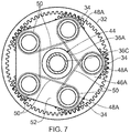
- Figure 7 shows an arrangement similar to that shown in Figures 4 and 5 but the long reinforcing fibres 50 in the star shape are wound fully around each aperture 49A of the annular member 47A of the first reinforcing structure 46A and the long reinforcing fibres 50 in the star shape are wound fully around each aperture 49B of the annular member 47B of the second reinforcing structure 46B.
- the long reinforcing fibres 50 are wound fully around each aperture 49A of the annular member 47A in turn and the long reinforcing fibres 50 are wound fully around each aperture 49B of the annular member 47B in turn.
- long reinforcing fibres 50 in the star shape are wound fully around each boss 48A or 48B of the first ring 36A or the second ring 36B.
- the long reinforcing fibres 50 in the star shape in the first reinforcing structure 46A are thus wound fully around a first end of each axle 40 and the long reinforcing fibres 50 in the star shape in the second reinforcing structure 46B are wound fully around a second end of each axle 40.
- the polymer matrix composite may be reinforced with carbon fibres or boron fibres.
- the polymer matrix composite may comprise an unsaturated polyester matrix, an epoxide matrix, a vinyl ester matrix or a polyamide matrix.
- the metal matrix composite may be reinforced with silicon carbide fibres, silicon nitride fibres or boron nitride fibres.
- the metal matrix composite may comprise an iron matrix, a steel matrix, a titanium matrix, a titanium alloy matrix, an aluminium matrix, an aluminium alloy matrix, a nickel matrix or a nickel alloy matrix.
- the ceramic matrix composite may be reinforced with silicon carbide fibres, silicon nitride fibres, alumina fibres, aluminosilicate fibres or mullite fibres.
- the ceramic matrix composite may comprise a silicon carbide matrix, a silicon nitride matrix, an alumina matrix, an aluminosilicate matrix or a mullite matrix.
- Each reinforcing structure with long reinforcing fibres may be made by making a fibre preform and then depositing a matrix material on and around the fibre preform.
- the matrix material is a polymer
- polymer matrix may be deposited onto the reinforcing fibres for example using resin transfer moulding.
- the matrix material is a metal
- the metal matrix may be deposited onto the reinforcing fibres using for example vapour deposition, e.g. physical vapour deposition, by thermal spraying or plasma spraying.
- the matrix material is a ceramic matrix
- the ceramic matrix may be deposited onto the reinforcing fibres by for example vapour deposition, e.g. chemical vapour deposition, or by applying a slurry.
- the primary structure comprises titanium and the reinforcing structure comprises a titanium matrix composite with silicon carbide reinforcing fibres.
- the primary structure comprises steel and the reinforcing structure comprises a titanium matrix composite with silicon carbide reinforcing fibres.
- the primary structure comprises titanium and the reinforcing structure comprises an iron matrix composite with silicon carbide reinforcing fibres.
- the primary structure comprises steel and the reinforcing structure comprises an iron matrix composite with silicon carbide reinforcing fibres.
- the primary structure comprises titanium and the reinforcing structure comprises a steel matrix composite with silicon carbide reinforcing fibres and in a sixth example the primary structure comprises steel and the reinforcing structure comprises a steel matrix composite with silicon carbide reinforcing fibres.
- the silicon carbide fibres may be replaced with silicon nitride fibres, titanium diboride fibres or boron nitride fibres.
- the primary structure comprises titanium with particulate reinforcement and the reinforcing structure comprises a titanium matrix composite with silicon carbide reinforcing fibres.
- the primary structure comprises steel with particulate reinforcement and the reinforcing structure comprises a titanium matrix composite with silicon carbide reinforcing fibres.
- the primary structure comprises titanium with particulate reinforcement and the reinforcing structure comprises an iron matrix composite with silicon carbide reinforcing fibres.
- the primary structure comprises steel with particulate reinforcement and the reinforcing structure comprises an iron matrix composite with silicon carbide reinforcing fibres.
- the primary structure comprises titanium with particulate reinforcement and the reinforcing structure comprises a steel matrix composite with silicon carbide reinforcing fibres and in a twelfth example the primary structure comprises steel with particulate reinforcement and the reinforcing structure comprises a steel matrix composite with silicon carbide reinforcing fibres.
- the silicon carbide fibres may be replaced with silicon nitride fibres, titanium diboride fibres or boron nitride fibres.
- the first and second reinforcing structures 46A and 46B may be welded, brazed or bonded to the first and second rings 36a and 36B of the primary structure 44 if they comprise similar materials, e.g. both comprise a metal.
- the first and second reinforcing structures 46A and 46B may be fastened, e.g. bolted, to the first and second rings 36a and 36B of the primary structure 44 if they comprise different or similar materials, e.g. one material comprises a metal and the other material comprises a ceramic or a polymer, one material comprises a ceramic and the other comprises a polymer, both materials comprise a metal, both materials comprise a polymer or both materials comprise a ceramic.
- the reinforcing structures with long reinforcing fibres have the reinforcing fibres aligned, or arranged, to carry the loads acting on the planet gear carrier and produce a stiffer structure.
- the short reinforcing fibres and the reinforcing particles are randomly distributed and are not aligned, or arranged, in the same manner as the long reinforcing fibres and therefore produce a structure with less stiffness than the long reinforcing fibres.
- the advantage of the present disclosure is that it enables the primary structure of the planet gear carrier to be made as small and lightweight as is practical while providing positioning of the planet gears.
- the reinforcing structures of the planet gear carrier are optimised to provide a stiff lightweight reinforcement for the primary structure so that the primary structure of the planet gear carrier is able to support the loads applied to the planet gears and planet gear bearings, which are generated by torque or centrifugally generated.
- a planet gear carrier comprising a primary structure and a reinforcing structure is also able to maintain the positions of the gears very accurately to maintain adequate gear performance in terms of controlling the tooth loading and the noise, or vibration, levels.
- the weight of the planet gear carrier is significantly reduced.
- a planet gear carrier comprising a primary structure and a reinforcing structure may be designed to have increased stiffness such that smaller, more efficient teeth may be provided on the sun gear, planet gears and annulus gear.
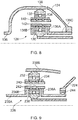
- Figure 8 shows an arrangement in which the low-pressure turbine 19 drives the fan 13 indirectly via the shaft 126, a gearbox 128 and a shaft 138.
- the gearbox 128 comprises a sun gear 130, an annulus gear 132, a plurality of planet gears 134 and a planet gear carrier 136.
- the sun gear 130 meshes with the planet gears 134 and the planet gears 134 mesh with the annulus gear 132.
- the planet gear carrier 136 enabling each planet gear 134 to rotate about its own axis independently.
- the planet gear carrier 136 is coupled to a static structure 124.
- the annulus gear 132 is coupled via the shaft 138 to the fan 13 in order to drive its rotation about the engine axis 9.
- the axes of the planet gears 134 are parallel to the engine axis 9.
- the planet gear carrier 136 comprises a first ring 136A, a second ring 136B spaced axially from the first ring 136A and a plurality of circumferentially spaced axles 140 which extend axially between the first ring 136A and the second ring 136B.
- Each planet gear 134 is rotatably mounted on a respective one of the axles 140 and an annular extension 136C extends axially from the first ring 136A.
- Each planet gear 134 is rotatably mounted in the planet gear carrier 136 by at least one planet gear bearing 142.
- the annular extension 136C is secured to the static structure 124.
- each planet gear 134 is rotatably mounted on the planet gear carrier 136 by two roller bearings 142.
- each planet gear 134 may be rotatably mounted on the planet gear carrier 136 by a journal bearing.
- a lubrication system is arranged to supply lubricant to the planet gear bearings 142, the sun gear 130 and the planet gears 134.
- the gearbox arrangement 128 of figure 8 may be provided with a planet gear carrier 136 with a primary structure 44 and reinforcing structure 46 as described with reference to Figures 4 and 5 , Figures 4 and 6 or Figures 4 and 7 .
- Figure 9 shows an arrangement in which the low-pressure turbine 19 drives two fans indirectly via the shaft 226, a gearbox 228 and shaft 238A and 238B.
- the gearbox 228 comprises a sun gear 230, an annulus gear 232, a plurality of planet gears 234 and a planet gear carrier 236.
- the sun gear 230 meshes with the planet gears 234 and the planet gears 234 mesh with the annulus gear 232.
- the planet gear carrier 236 enabling each planet gear 234 to rotate about its own axis independently.
- the planet gear carrier 236 is coupled via the shaft 238A to a first propulsor (not shown) and the annulus gear 232 is coupled via the shaft 238B to a second propulsor (not shown) in order to drive their rotation about the engine axis 9.
- the propulsors are driven to rotate in opposite rotational directions.
- the axes of the planet gears 234 are parallel to the engine axis 9.
- the planet gear carrier 236 comprises a first ring 236A, a second ring 236B spaced axially from the first ring 236A and a plurality of circumferentially spaced axles 240 which extend axially between the first ring 236A and the second ring 236B.
- Each planet gear 234 is rotatably mounted on a respective one of the axles 240 and an annular extension 236C extends axially from the first ring 236A.
- Each planet gear 234 is rotatably mounted in the planet gear carrier 236 by at least one planet gear bearing 242.
- the annular extension 236C is rotatably mounted in the static structure 224 by a bearing 244.
- each planet gear 234 is rotatably mounted on the planet gear carrier 236 by two roller bearings 242.
- each planet gear 234 may be rotatably mounted on the planet gear carrier 236 by a journal bearing.
- a lubrication system 246 is arranged to supply lubricant to the planet gear bearings 242, the sun gear 230 and the planet gears 234.
- the gearbox arrangement 228 of Figure 9 may be provided with a planet gear carrier 236 with a primary structure 44 and reinforcing structure 46 as described with reference to Figures 4 and 5 , Figures 4 and 6 or Figures 4 and 7 .
- the sun gear, the annulus gear, the carrier and the shaft are coaxial.
- the lubricant e.g. oil
- the gas turbine engine comprises a propulsor, an intermediate-pressure compressor, a high-pressure compressor, a high-pressure turbine and a low-pressure turbine, the high-pressure turbine is arranged to directly drive the high-pressure compressor, the low-pressure turbine is arranged to directly drive the intermediate-pressure compressor and the low-pressure turbine is arranged to drive the propulsor via a gearbox.
- the gas turbine engine comprises a propulsor, an intermediate-pressure compressor, a high-pressure compressor, a high-pressure turbine and a low-pressure turbine, the high-pressure turbine is arranged to directly drive the high-pressure compressor, the low-pressure turbine is arranged to directly drive the propulsor and the low-pressure turbine is arranged to drive the intermediate-pressure compressor via a gearbox.
- the gas turbine engine comprises a propulsor, an intermediate-pressure compressor, a high-pressure compressor, a high-pressure turbine, an intermediate-pressure turbine and a low-pressure turbine
- the high-pressure turbine is arranged to directly drive the high-pressure compressor
- the intermediate-pressure turbine is arranged to directly drive the intermediate-pressure compressor
- the low-pressure turbine is arranged to drive the propulsor via a gearbox.
- the gas turbine engine may comprise a propulsor, a high-pressure compressor, a high-pressure turbine and a low-pressure turbine, the high-pressure turbine is arranged to directly drive the high-pressure compressor and the low-pressure turbine is arranged to drive the propulsor via a gearbox.
- the gas turbine engine comprises a first propulsor, a second propulsor, an intermediate-pressure compressor, a high-pressure compressor, a high-pressure turbine, an intermediate-pressure turbine and a low-pressure turbine
- the high-pressure turbine is arranged to directly drive the high-pressure compressor
- the intermediate-pressure turbine is arranged to directly drive the intermediate-pressure compressor
- the low-pressure turbine is arranged to drive the first propulsor and the second propulsor via a gearbox.
- the gas turbine engine comprises a first propulsor, a second propulsor, a low-pressure compressor, a high-pressure compressor, a high-pressure turbine, a low-pressure turbine and a free power turbine
- the high-pressure turbine is arranged to directly drive the high-pressure compressor
- the low-pressure turbine is arranged to directly drive the low-pressure compressor
- the free power turbine is arranged to drive the first propulsor and the second propulsor via a gearbox.
- the gas turbine engine comprises a first propulsor, a second propulsor, a low-pressure compressor, a high-pressure compressor, a high-pressure turbine and a low-pressure turbine
- the high-pressure turbine is arranged to directly drive the high-pressure compressor
- the low-pressure turbine is arranged to directly drive the low-pressure compressor
- the low-pressure turbine is arranged to drive the first propulsor and the second propulsor via a gearbox.
- the sun gear may be driven by a low-pressure turbine, the annulus gear may be secured to static structure and the carrier may be arranged to drive a propulsor.
- the sun gear may be driven by the low-pressure turbine, the carrier may be secured to static structure and the annulus gear may be arranged to drive a propulsor.
- each planet gear rotates about its own axis and the carrier does not rotate about the engine axis.
- the axes of the planet gears are parallel to the engine axis.
- the carrier may be driven by the low-pressure turbine, the sun gear may be secured to static structure and the annulus gear may be arranged to drive a propulsor.
- the sun gear may be driven by the low-pressure turbine, the carrier may be arranged to drive a first propulsor and the annulus gear may be arranged to drive a second propulsor.
- gearbox may be arranged in a solar gearbox arrangement, e.g. the sun gear is secured to static structure and either the carrier is driven by an input drive shaft and the annulus gear drives an output drive shaft or the annulus gear is driven by an input drive shaft and the carrier drives an output drive shaft.
- the propulsor may be a fan or a propeller.
Landscapes
- Engineering & Computer Science (AREA)
- General Engineering & Computer Science (AREA)
- Chemical & Material Sciences (AREA)
- Combustion & Propulsion (AREA)
- Mechanical Engineering (AREA)
- Retarders (AREA)
- Structures Of Non-Positive Displacement Pumps (AREA)
Abstract
Description
- The present disclosure concerns a geared gas turbine engine and in particular to a geared turbofan gas turbine engine or a geared turbo propeller gas turbine engine.
- A geared turbofan gas turbine engine or a geared turbo propeller gas turbine engine comprises a gearbox which is arranged to drive the fan or propeller. The gearbox allows the fan, or the propeller, to rotate at a speed less than the speed the speed of rotation of a turbine driving the gearbox. This enables the efficiency of the fan, or the propeller, and the efficiency of the turbine to be improved.
- In one arrangement the gearbox comprises a sun gear which is arranged to be driven by a turbine, an annulus gear which is arranged to be static, planet gears meshing with the sun gear and the annulus gear and a carrier which is arranged to drive the fan, or the propeller, if the gearbox is a planetary gearbox. In another arrangement the gearbox comprises a sun gear which is arranged to be driven by a turbine, an annulus gear which is arranged to drive the fan, or the propeller, planet gears meshing with the sun gear and the annulus gear and a carrier which is arranged to be static if the gearbox is a star gearbox. In a further arrangement the gearbox comprises a sun gear which is arranged to be driven by a turbine, an annulus gear which is arranged to drive a first fan, or a first propeller, planet gears meshing with the sun gear and the annulus gear and a carrier which is arranged to drive a second fan, or a second propeller, if the gearbox is a differential gearbox.
- In large, high speed, gearboxes the gearbox must endure very high loads due to centrifugal loading from the rotating planet gears and the basic torque load which the gearbox is arranged to transmit. The carrier of the gearbox is required to support the loads applied to the planet gears and planet gear bearings, which may be generated by torque or centrifugally generated. The carrier must also maintain the positions of the gears very accurately to maintain adequate gear performance in terms of controlling the tooth loading and the noise, or vibration, levels.
- The carrier comprises one or more disc like structures, or ring structures, which are arranged to transmit both the torsional load and the radial load and control deflections of the carrier within the limits required for the gearbox. Torsional loads may produce torsional displacements of the gears which may result in improved load sharing between the gears. However, radial loads may produce radial displacements of the planet gears relative to the sun and annulus gears which may result in transmission errors and hence noise and vibration and tooth overloading.
- In order to overcome this problem it is known to make the gears with larger gear teeth so that the gears are less sensitive to the radial displacements, but this has the disadvantage of increasing the inefficiency of the gearbox and increasing the tendency for scuffing. It is also known to make the carrier stiffer/stronger by increasing the mass of the carrier, but this mass has to be added at a large diameter region of the carrier which in turn generates further centrifugal loads and has the disadvantage of increasing the weight of the carrier, and/or increasing the diameter of the rim of the carrier, and hence increasing the weight of the geared gas turbine engine.
- The present disclosure seeks to provide a geared gas turbine engine which reduces or overcomes this problem.
- According to a first aspect of the present disclosure there is provided a gas turbine engine comprising a gearbox, the gearbox comprising a sun gear, an annulus gear, a plurality of planet gears and a carrier, the sun gear meshing with the planet gears and the planet gears meshing with the annulus gear, the carrier comprising a primary structure and at least one reinforcing structure, the primary structure comprising a first material and the at least one reinforcing structure comprising a second material, the primary structure comprising a first ring, a second ring spaced axially from the first ring and a plurality of circumferentially spaced axles extending axially between the first ring and the second ring, each planet gear being rotatably mounted on a respective one of the axles, the at least one reinforcing structure being secured to the primary structure, and the at least one reinforcing structure comprising a particulate reinforced material or a fibre reinforced material.
- According to a second aspect of the disclosure there is provided a gearbox, the gearbox comprising a sun gear, an annulus gear, a plurality of planet gears and a carrier, the sun gear meshing with the planet gears and the planet gears meshing with the annulus gear, the carrier comprising a primary structure and at least one reinforcing structure, the primary structure comprising a first material and the at least one reinforcing structure comprising a second material, the primary structure comprising a first ring, a second ring spaced axially from the first ring and a plurality of circumferentially spaced axles extending axially between the first ring and the second ring, each planet gear being rotatably mounted on a respective one of the axles, the at least one reinforcing structure being secured to the primary structure, and the at least one reinforcing structure comprising a particulate reinforced material or a fibre reinforced material.
- The first ring and the second ring may be secured together. The first ring and the second ring may be fastened, bolted, together.
- The at least one reinforcing structure may be fastened, bonded, welded or brazed to the primary structure. The at least one reinforcing structure may be secured to the first ring or the second ring. A first reinforcing structure may be secured to the first ring and a second reinforcing structure may be secured to the second ring.
- The first ring may comprise an annular plate or annular framework.
- The second ring may comprise an annular plate or annular framework.
- The annular plate may comprise a plurality of bosses and each boss is aligned with respective one of the axles. The annular framework may comprise a plurality of bosses, each boss is aligned with a respective one of the axles, and a radially inner annular member and a radially outer annular member interconnecting the bosses.
- The primary structure may comprise an unreinforced material. The primary structure may comprise an alloy. The primary structure may comprise steel, titanium or a titanium alloy. The reinforcing structure may comprise a polymer matrix composite, a metal matrix composite or a ceramic matrix composite. The reinforcing structure may comprise a polymer matrix composite with long reinforcing fibres, a metal matrix composite with long reinforcing fibres or a ceramic matrix composite with long reinforcing fibres.
- The first and second rings may have a plurality of circumferentially spaced bosses, each axle locating in a corresponding one of the bosses in the first ring and a corresponding one of the bosses in the second ring. The long reinforcing fibres may be arranged into at least one continuous loop arranged at a diameter greater than the diameter at which the bosses are arranged. The long reinforcing fibres may be arranged in a star shape. The long reinforcing fibres in the star shape may be wound partially around each boss of the first ring or the second ring. The long reinforcing fibres in the star shape may be wound fully around each boss of the first ring or the second ring. The reinforcing structure may comprise a polymer matrix composite with short reinforcing fibres, a metal matrix composite with short reinforcing fibres or a ceramic matrix composite with short reinforcing fibres. The reinforcing structure may comprise a polymer matrix composite with reinforcing particles, a metal matrix composite with reinforcing particles or a ceramic matrix composite with reinforcing particles.
- The primary structure may comprise a particulate reinforced material. The primary structure may comprise a polymer matrix composite, a metal matrix composite or a ceramic matrix composite. The reinforcing structure may comprise a polymer matrix composite with long reinforcing fibres, a metal matrix composite with long reinforcing fibres or a ceramic matrix composite with long reinforcing fibres. The first and second rings may have a plurality of circumferentially spaced bosses, each axle locating in a corresponding one of the bosses in the first ring and a corresponding one of the bosses in the second ring. The long reinforcing fibres may be arranged into at least one continuous loop arranged at a diameter greater than the diameter at which the bosses are arranged. The long reinforcing fibres may be arranged in a star shape. The long reinforcing fibres in the star shape may be wound partially around each boss of the first ring or the second ring. The long reinforcing fibres in the star shape may be wound fully around each boss of the first ring or the second ring.
- The polymer matrix composite may be reinforced with carbon fibres, aramid fibres, e.g. Kevlar (RTM) fibres, or boron fibres. The polymer matrix composite may comprise an unsaturated polyester matrix, an epoxide matrix, a vinyl ester matrix or a polyamide matrix. The metal matrix composite may be reinforced with silicon carbide fibres, silicon nitride fibres or boron nitride fibres. The metal matrix composite may comprise a steel matrix, a titanium matrix or a titanium alloy matrix. The ceramic matrix composite may be reinforced with silicon carbide fibres, silicon nitride fibres, alumina fibres, aluminosilicate fibres or mullite fibres. The ceramic matrix composite may comprise a silicon carbide matrix, a silicon nitride matrix, an alumina matrix, an aluminosilicate matrix or a mullite matrix.
- Each planet gear may be rotatably mounted on the carrier by a journal bearing and/or at least one rolling element bearing.
- Each planet gear may be rotatably mounted on the carrier by two rolling element bearings.
- The carrier may be connected to an output shaft and the annulus gear is connected to a static structure.
- The carrier may be connected to a static structure and the annulus gear is connected to an output shaft.
- The carrier may be connected to an output shaft and the annulus gear is connected to an output shaft.
- The gas turbine engine may comprise a propulsor, an intermediate-pressure compressor, a high-pressure compressor, a high-pressure turbine and a low-pressure turbine, the high-pressure turbine is arranged to directly drive the high-pressure compressor, the low-pressure turbine is arranged to directly drive the intermediate-pressure compressor and the low-pressure turbine is arranged to drive the propulsor via a gearbox.
- The gas turbine engine may comprise a propulsor, an intermediate-pressure compressor, a high-pressure compressor, a high-pressure turbine and a low-pressure turbine, the high-pressure turbine is arranged to directly drive the high-pressure compressor, the low-pressure turbine is arranged to directly drive the propulsor and the low-pressure turbine is arranged to drive the intermediate-pressure compressor via a gearbox.
- The gas turbine engine may comprise a propulsor, an intermediate-pressure compressor, a high-pressure compressor, a high-pressure turbine, an intermediate-pressure turbine and a low-pressure turbine, the high-pressure turbine is arranged to directly drive the high-pressure compressor, the intermediate-pressure turbine is arranged to directly drive the intermediate-pressure compressor and the low-pressure turbine is arranged to drive the propulsor via a gearbox.
- The gas turbine engine may comprise a propulsor, a high-pressure compressor, a high-pressure turbine and a low-pressure turbine, the high-pressure turbine is arranged to directly drive the high-pressure compressor and the low-pressure turbine is arranged to drive the propulsor via a gearbox.
- Alternatively, the gas turbine engine comprises a first propulsor, a second propulsor, an intermediate-pressure compressor, a high-pressure compressor, a high-pressure turbine, an intermediate-pressure turbine and a low-pressure turbine, the high-pressure turbine is arranged to directly drive the high-pressure compressor, the intermediate-pressure turbine is arranged to drive the intermediate-pressure compressor and the low-pressure turbine is arranged to drive the first propulsor and the second propulsor via a gearbox.
- The sun gear may be driven by the low-pressure turbine, the annulus gear may be secured to static structure and the carrier may be arranged to drive the propulsor.
- The sun gear may be driven by the low-pressure turbine, the carrier may be secured to static structure and the annulus gear may be arranged to drive the propulsor.
- The carrier may be driven by the low-pressure turbine, the sun gear may be secured to static structure and the annulus gear may be arranged to drive a propulsor.
- The sun gear may be driven by the low-pressure turbine, the carrier may be arranged to drive a first propulsor and the annulus gear may be arranged to drive a second propulsor.
- The propulsor may be a fan or a propeller.
- The sun gear, the planet gears and the annulus gear may each comprise two sets of helical gear teeth.
- Alternatively, the sun gear, the planet gears and the annulus gear may each comprise one set of helical gear teeth.
- The skilled person will appreciate that except where mutually exclusive, a feature described in relation to any one of the above aspects of the invention may be applied mutatis mutandis to any other aspect of the invention.
- Embodiments of the disclosure will now be described by way of example only, with reference to the Figures, in which:
-
Figure 1 is a part sectional side view of a geared turbofan gas turbine engine according to the present disclosure. -
Figure 2 is an enlarged part sectional side view of a portion of the geared turbofan gas turbine engine shown inFigure 1 . -
Figure 3 is an enlarged cross-sectional view though the gearbox shown inFigure 2 . -
Figure 4 is a further enlarged cross-sectional view of the gearbox shown inFigure 3 . -
Figure 5 is a view in the direction of Arrow A of the gearbox shown inFigure 4 . -
Figure 6 is an alternative view in the direction of Arrow A of the gearbox shown inFigure 4 . -
Figure 7 is a further alternative view in the direction of Arrow A of the gearbox shown inFigure 4 . -
Figure 8 is an alternative enlarged cross-sectional view though the gearbox shown inFigure 2 . -
Figure 9 is a further alternative enlarged cross-sectional view though the gearbox shown inFigure 2 . - With reference to
Figures 1 and 2 , a geared turbofan gas turbine engine is generally indicated at 10, having a principal androtational axis 9. The engine 10 comprises, in axial flow series, anair intake 12, apropulsive fan 13, an intermediate-pressure, or booster,compressor 14, a high-pressure compressor 15,combustion equipment 16, a high-pressure turbine 17, a low-pressure turbine 19 and acore exhaust nozzle 20. The intermediate-pressure compressor 14, the high-pressure compressor 15, thecombustion equipment 16, the high-pressure turbine 17 and the low-pressure turbine 19 form acore engine 11. A nacelle 21 generally surrounds the engine 10 and defines theintake 12, abypass duct 22 and abypass exhaust nozzle 18. - The gas turbine engine 10 works in the conventional manner so that air entering the
intake 12 is compressed by thefan 13 to produce two air flows: a first air flow A into the intermediate-pressure compressor 14 and a second air flow B which passes through thebypass duct 22 to provide the majority of the propulsive thrust. The intermediate-pressure compressor 14 compresses the air flow directed into it before delivering that air to the high-pressure compressor 15 where further compression takes place. - The compressed air exhausted from the high-
pressure compressor 15 is directed into thecombustion equipment 16 where it is mixed with fuel and the mixture combusted. The resultant hot combustion products then expand through, and thereby drive the high and low-pressure turbines core nozzle 20 to provide additional propulsive thrust. The high-pressure turbine 17 drives the high-pressure compressor 15 by ashaft 23. The low-pressure turbine 19 drives the intermediate-pressure compressor 14 directly viashafts pressure turbine 19 drives thefan 13 indirectly via theshaft 26, agearbox 28 and ashaft 38. Thegearbox 28 comprises asun gear 30, anannulus gear 32, a plurality of planet gears 34 and aplanet gear carrier 36. Thesun gear 30 meshes with the planet gears 34 and the planet gears 34 mesh with theannulus gear 32. Theplanet gear carrier 36 constrains the planet gears 34 to precess around thesun gear 30 in synchronicity whilst enabling eachplanet gear 34 to rotate about its own axis independently. Theplanet gear carrier 36 is coupled via theshaft 38 to thefan 13 in order to drive its rotation about theengine axis 9. Theannulus gear 32 is coupled to astatic structure 24. The axes of the planet gears 34 and the axis of theplanet gear carrier 36 are parallel to theengine axis 9. Theshaft 38 is rotatably mounted in static structure by one or more bearings, e.g. rolling element bearings, e.g. roller bearings or ball bearings. - The
gearbox 28 is shown more clearly infigures 3, 4 and5 and theplanet gear carrier 36 comprises afirst ring 36A, asecond ring 36B spaced axially from thefirst ring 36A, anextension shaft 36C and a plurality of circumferentially spacedaxles 40 which extend axially between thefirst ring 36A and thesecond ring 36B. Theextension shaft 36C of theplanet gear carrier 36 is rotatably mounted in thestatic structure 24 by a bearing 43. Theaxles 40 are also arranged parallel to theengine axis 9 and thus the axis of thegearbox 28. The axially spaced ends of eachaxle 40 are secured to theplanet gear carrier 36, e.g. to thefirst ring 36A and thesecond ring 36B. The first andsecond rings bosses axle 40 locates in an aperture extending through a corresponding one of thebosses 48A in thefirst ring 36A and in an aperture extending through a corresponding one of thebosses 48B in thesecond ring 36B. Thefirst ring 36A and thesecond ring 36B are secured together. Thefirst ring 36A and thesecond ring 36B may be fastened, e.g. bolted, together or welded, brazed or bonded together. In this arrangement eachplanet gear 36 is arranged around a respective one of theaxles 40, eachplanet gear 34 is rotatably mounted in theplanet gear carrier 36 and in particular eachplanet gear 34 is rotatably mounted on a respective one of theaxles 40 by a bearingarrangement 42. Each bearingarrangement 42 comprises a journal bearing or a rolling element bearing. In this particular arrangement each bearingarrangement 42 comprises two roller bearings. A lubrication system is arranged to supply lubricant to the planetgear bearing arrangements 42, thesun gear 30 and the planet gears 34. - The
planet gear carrier 36 comprises aprimary structure 44 and at least one reinforcing structure 46, as shown more clearly inFigures 4 and5 . Theprimary structure 44 comprises a first material and the at least one reinforcing structure 46 comprises a second material. Theprimary structure 44 comprises thefirst ring 36A, thesecond ring 36B spaced axially from thefirst ring 36A and the plurality of circumferentially spacedaxles 40 extending axially between thefirst ring 36A and thesecond ring 36B. Theprimary structure 44 may also comprise theextension shaft 36C. The at least one reinforcing structure 46 is secured to theprimary structure 44. Theprimary structure 44 comprises an unreinforced material or a particulate reinforced material and the at least one reinforcing structure 46 comprises a reinforced material. - The at least one reinforcing structure 46 is fastened, bonded, welded or brazed to the
primary structure 44. The at least one reinforcing structure 46 is secured to thefirst ring 36A or thesecond ring 36B. In this particular arrangement the reinforcing structure 46 comprise a first reinforcingstructure 46A secured to thefirst ring 36A and a second reinforcingstructure 46B secured to thesecond ring 36B. - The
first ring 36A comprises an annular plate or annular framework and thesecond ring 36B comprises an annular plate or annular framework. Each of the annular plates is defined by circular radially inner and radially outer peripheries, by polygonal radially inner and outer peripheries, by a circular radially inner periphery and a polygonal radially outer periphery or a polygonal radially inner periphery and a circular radially outer periphery. Each of the annular plates has the plurality of circumferentially spacedbosses bosses bosses - The first reinforcing
structure 46A and the second reinforcingstructure 46B each comprise anannular member annular members annular members apertures bosses second rings - In one arrangement the
primary structure 44 comprise an unreinforced material and the reinforcing structure 46 comprises a fibre reinforced material or a particulate reinforced material. Theprimary structure 44 comprises a metal and the metal may be an alloy, for example the primary structure may comprise steel, titanium, a titanium alloy, aluminium, an aluminium alloy, nickel or a nickel alloy. The reinforcing structure 46 comprises a polymer matrix composite, a metal matrix composite or a ceramic matrix composite. The reinforcing structure 46 may comprise a polymer matrix composite with long reinforcing fibres, a metal matrix composite with long reinforcing fibres or a ceramic matrix composite with long reinforcing fibres. Alternatively, the reinforcing structure 46 comprises a polymer matrix composite with short reinforcing fibres, a metal matrix composite with short reinforcing fibres or a ceramic matrix composite with short reinforcing fibres. In a further alternative, the reinforcing structure 46 comprises a polymer matrix composite with reinforcing particles, a metal matrix composite with reinforcing particles or a ceramic matrix composite with reinforcing particles. - In another arrangement the
primary structure 44 comprises a particulate reinforced material and the reinforcing structure 46 comprises a fibre reinforced material or a particulate reinforced material. Theprimary structure 44 comprises a polymer matrix composite, a metal matrix composite or a ceramic matrix composite. The reinforcing structure 46 comprises a polymer matrix composite, a metal matrix composite or a ceramic matrix composite. The reinforcing structure 46 may comprise a polymer matrix composite with long reinforcing fibres, a metal matrix composite with long reinforcing fibres or a ceramic matrix composite with long reinforcing fibres. Alternatively, the reinforcing structure 46 comprises a polymer matrix composite with short reinforcing fibres, a metal matrix composite with short reinforcing fibres or a ceramic matrix composite with short reinforcing fibres. In a further alternative, the reinforcing structure 46 comprises a polymer matrix composite with reinforcing particles, a metal matrix composite with reinforcing particles or a ceramic matrix composite with reinforcing particles. -
Figures 4 and5 show an arrangement in which thefirst ring 36A of theprimary structure 44 comprises a particulate reinforced material and thesecond ring 36B of theprimary structure 44 comprises a metal. Thefirst ring 36A of theprimary structure 44 comprises reinforcingparticles 51 in amatrix material 53. Thefirst ring 36A of theprimary structure 44 comprises a polymer matrix composite, a metal matrix composite or a ceramic matrix composite and the metal of thesecond ring 36B of theprimary structure 44 may be an alloy, for example steel, titanium, a titanium alloy, aluminium, an aluminium alloy, nickel or a nickel alloy. The reinforcingstructures structures structures fibres 50 in amatrix material 52. The long reinforcingfibres 50 are arranged in a star shape in both of the reinforcingstructures fibres 50 in the star shape are wound partially around eachaperture 49A of the first reinforcingstructure 46A and the long reinforcingfibres 50 in the star shape are wound partially around eachaperture 49B of the second reinforcingstructure 46B. The long reinforcingfibres 50 in the star shape are thus wound partially around eachboss 48A of thefirst ring 36A and the long reinforcingfibres 50 in the star shape are wound partially around eachboss 48B of thesecond ring 36B. The long reinforcingfibres 50 in the star shape in the first reinforcingstructure 46A are thus wound partially around a first end of eachaxle 40 and the long reinforcingfibres 50 in the star shape in the second reinforcingstructure 46B are wound partially around a second end of eachaxle 40. The long reinforcingfibres 50 are wound around circumferentiallyalternate apertures apertures annular member adjacent aperture annular member bolts 54,washers 56 and nuts (not shown) are used to secure the first and second reinforcingstructures second rings 36a and 36B of theprimary structure 44. -
Figure 6 shows an arrangement similar to that shown inFigures 4 and5 but the long reinforcingfibres 50 are wound into at least one continuous loop between theapertures 49A and the radially outer periphery of theannular member 47A of the first reinforcingstructure 46A and the long reinforcingfibres 50 are wound into at least one continuous loop between theapertures 49B and the radially outer periphery of theannular member 47B of the second reinforcingstructure 46B. Thus, the long reinforcingfibres 50 are arranged into at least one continuous loop arranged at a diameter greater than the diameter at which thebosses fibres 50 of the first reinforcingstructure 46A are wound into at least one continuous loop between a first end of eachaxle 40 and the radially outer periphery of the first reinforcingstructure 46A and the long reinforcingfibres 50 are wound into at least one continuous loop between the second end of eachaxle 40 and the radially outer periphery of the second reinforcingstructure 46B. -
Figure 7 shows an arrangement similar to that shown inFigures 4 and5 but the long reinforcingfibres 50 in the star shape are wound fully around eachaperture 49A of theannular member 47A of the first reinforcingstructure 46A and the long reinforcingfibres 50 in the star shape are wound fully around eachaperture 49B of theannular member 47B of the second reinforcingstructure 46B. The long reinforcingfibres 50 are wound fully around eachaperture 49A of theannular member 47A in turn and the long reinforcingfibres 50 are wound fully around eachaperture 49B of theannular member 47B in turn. Thus, long reinforcingfibres 50 in the star shape are wound fully around eachboss first ring 36A or thesecond ring 36B. The long reinforcingfibres 50 in the star shape in the first reinforcingstructure 46A are thus wound fully around a first end of eachaxle 40 and the long reinforcingfibres 50 in the star shape in the second reinforcingstructure 46B are wound fully around a second end of eachaxle 40. - The polymer matrix composite may be reinforced with carbon fibres or boron fibres. The polymer matrix composite may comprise an unsaturated polyester matrix, an epoxide matrix, a vinyl ester matrix or a polyamide matrix. The metal matrix composite may be reinforced with silicon carbide fibres, silicon nitride fibres or boron nitride fibres. The metal matrix composite may comprise an iron matrix, a steel matrix, a titanium matrix, a titanium alloy matrix, an aluminium matrix, an aluminium alloy matrix, a nickel matrix or a nickel alloy matrix. The ceramic matrix composite may be reinforced with silicon carbide fibres, silicon nitride fibres, alumina fibres, aluminosilicate fibres or mullite fibres. The ceramic matrix composite may comprise a silicon carbide matrix, a silicon nitride matrix, an alumina matrix, an aluminosilicate matrix or a mullite matrix.
- Each reinforcing structure with long reinforcing fibres may be made by making a fibre preform and then depositing a matrix material on and around the fibre preform. If the matrix material is a polymer, polymer matrix may be deposited onto the reinforcing fibres for example using resin transfer moulding. If the matrix material is a metal, the metal matrix may be deposited onto the reinforcing fibres using for example vapour deposition, e.g. physical vapour deposition, by thermal spraying or plasma spraying. If the matrix material is a ceramic matrix, the ceramic matrix may be deposited onto the reinforcing fibres by for example vapour deposition, e.g. chemical vapour deposition, or by applying a slurry.
- In a first example the primary structure comprises titanium and the reinforcing structure comprises a titanium matrix composite with silicon carbide reinforcing fibres. In a second example the primary structure comprises steel and the reinforcing structure comprises a titanium matrix composite with silicon carbide reinforcing fibres. In a third example the primary structure comprises titanium and the reinforcing structure comprises an iron matrix composite with silicon carbide reinforcing fibres. In a fourth example the primary structure comprises steel and the reinforcing structure comprises an iron matrix composite with silicon carbide reinforcing fibres. In a fifth example the primary structure comprises titanium and the reinforcing structure comprises a steel matrix composite with silicon carbide reinforcing fibres and in a sixth example the primary structure comprises steel and the reinforcing structure comprises a steel matrix composite with silicon carbide reinforcing fibres. In each of these examples the silicon carbide fibres may be replaced with silicon nitride fibres, titanium diboride fibres or boron nitride fibres.
- In a seventh example the primary structure comprises titanium with particulate reinforcement and the reinforcing structure comprises a titanium matrix composite with silicon carbide reinforcing fibres. In an eighth example the primary structure comprises steel with particulate reinforcement and the reinforcing structure comprises a titanium matrix composite with silicon carbide reinforcing fibres. In a ninth example the primary structure comprises titanium with particulate reinforcement and the reinforcing structure comprises an iron matrix composite with silicon carbide reinforcing fibres. In a tenth example the primary structure comprises steel with particulate reinforcement and the reinforcing structure comprises an iron matrix composite with silicon carbide reinforcing fibres. In an eleventh example the primary structure comprises titanium with particulate reinforcement and the reinforcing structure comprises a steel matrix composite with silicon carbide reinforcing fibres and in a twelfth example the primary structure comprises steel with particulate reinforcement and the reinforcing structure comprises a steel matrix composite with silicon carbide reinforcing fibres. In each of these examples the silicon carbide fibres may be replaced with silicon nitride fibres, titanium diboride fibres or boron nitride fibres.
- The first and second reinforcing
structures second rings 36a and 36B of theprimary structure 44 if they comprise similar materials, e.g. both comprise a metal. The first and second reinforcingstructures second rings 36a and 36B of theprimary structure 44 if they comprise different or similar materials, e.g. one material comprises a metal and the other material comprises a ceramic or a polymer, one material comprises a ceramic and the other comprises a polymer, both materials comprise a metal, both materials comprise a polymer or both materials comprise a ceramic. - The reinforcing structures with long reinforcing fibres have the reinforcing fibres aligned, or arranged, to carry the loads acting on the planet gear carrier and produce a stiffer structure. The short reinforcing fibres and the reinforcing particles are randomly distributed and are not aligned, or arranged, in the same manner as the long reinforcing fibres and therefore produce a structure with less stiffness than the long reinforcing fibres.
- The advantage of the present disclosure is that it enables the primary structure of the planet gear carrier to be made as small and lightweight as is practical while providing positioning of the planet gears. The reinforcing structures of the planet gear carrier are optimised to provide a stiff lightweight reinforcement for the primary structure so that the primary structure of the planet gear carrier is able to support the loads applied to the planet gears and planet gear bearings, which are generated by torque or centrifugally generated. A planet gear carrier comprising a primary structure and a reinforcing structure is also able to maintain the positions of the gears very accurately to maintain adequate gear performance in terms of controlling the tooth loading and the noise, or vibration, levels. The weight of the planet gear carrier is significantly reduced. Alternatively, a planet gear carrier comprising a primary structure and a reinforcing structure may be designed to have increased stiffness such that smaller, more efficient teeth may be provided on the sun gear, planet gears and annulus gear.
-
Figure 8 shows an arrangement in which the low-pressure turbine 19 drives thefan 13 indirectly via the shaft 126, agearbox 128 and ashaft 138. Thegearbox 128 comprises asun gear 130, anannulus gear 132, a plurality of planet gears 134 and a planet gear carrier 136. Thesun gear 130 meshes with the planet gears 134 and the planet gears 134 mesh with theannulus gear 132. The planet gear carrier 136 enabling eachplanet gear 134 to rotate about its own axis independently. The planet gear carrier 136 is coupled to astatic structure 124. Theannulus gear 132 is coupled via theshaft 138 to thefan 13 in order to drive its rotation about theengine axis 9. The axes of the planet gears 134 are parallel to theengine axis 9. The planet gear carrier 136 comprises afirst ring 136A, asecond ring 136B spaced axially from thefirst ring 136A and a plurality of circumferentially spacedaxles 140 which extend axially between thefirst ring 136A and thesecond ring 136B. Eachplanet gear 134 is rotatably mounted on a respective one of theaxles 140 and anannular extension 136C extends axially from thefirst ring 136A. Eachplanet gear 134 is rotatably mounted in the planet gear carrier 136 by at least oneplanet gear bearing 142. Theannular extension 136C is secured to thestatic structure 124. In this particular embodiment eachplanet gear 134 is rotatably mounted on the planet gear carrier 136 by tworoller bearings 142. Alternatively eachplanet gear 134 may be rotatably mounted on the planet gear carrier 136 by a journal bearing. A lubrication system is arranged to supply lubricant to theplanet gear bearings 142, thesun gear 130 and the planet gears 134. Thegearbox arrangement 128 offigure 8 may be provided with a planet gear carrier 136 with aprimary structure 44 and reinforcing structure 46 as described with reference toFigures 4 and5 ,Figures 4 and6 orFigures 4 and7 . -
Figure 9 shows an arrangement in which the low-pressure turbine 19 drives two fans indirectly via the shaft 226, agearbox 228 andshaft gearbox 228 comprises asun gear 230, anannulus gear 232, a plurality of planet gears 234 and a planet gear carrier 236. Thesun gear 230 meshes with the planet gears 234 and the planet gears 234 mesh with theannulus gear 232. The planet gear carrier 236 enabling eachplanet gear 234 to rotate about its own axis independently. The planet gear carrier 236 is coupled via theshaft 238A to a first propulsor (not shown) and theannulus gear 232 is coupled via theshaft 238B to a second propulsor (not shown) in order to drive their rotation about theengine axis 9. The propulsors are driven to rotate in opposite rotational directions. The axes of the planet gears 234 are parallel to theengine axis 9. The planet gear carrier 236 comprises afirst ring 236A, asecond ring 236B spaced axially from thefirst ring 236A and a plurality of circumferentially spacedaxles 240 which extend axially between thefirst ring 236A and thesecond ring 236B. Eachplanet gear 234 is rotatably mounted on a respective one of theaxles 240 and an annular extension 236C extends axially from thefirst ring 236A. Eachplanet gear 234 is rotatably mounted in the planet gear carrier 236 by at least oneplanet gear bearing 242. The annular extension 236C is rotatably mounted in thestatic structure 224 by abearing 244. In this particular embodiment eachplanet gear 234 is rotatably mounted on the planet gear carrier 236 by tworoller bearings 242. Alternatively eachplanet gear 234 may be rotatably mounted on the planet gear carrier 236 by a journal bearing. A lubrication system 246 is arranged to supply lubricant to theplanet gear bearings 242, thesun gear 230 and the planet gears 234. Thegearbox arrangement 228 ofFigure 9 may be provided with a planet gear carrier 236 with aprimary structure 44 and reinforcing structure 46 as described with reference toFigures 4 and5 ,Figures 4 and6 orFigures 4 and7 . - In each of the arrangements described above the sun gear, the annulus gear, the carrier and the shaft are coaxial.
- In each of the arrangements described above the lubricant, e.g. oil, lubricates and cools the sun, annulus and planet gears and the bearings of the planet gears.
- As described above, the gas turbine engine comprises a propulsor, an intermediate-pressure compressor, a high-pressure compressor, a high-pressure turbine and a low-pressure turbine, the high-pressure turbine is arranged to directly drive the high-pressure compressor, the low-pressure turbine is arranged to directly drive the intermediate-pressure compressor and the low-pressure turbine is arranged to drive the propulsor via a gearbox.
- Alternatively, the gas turbine engine comprises a propulsor, an intermediate-pressure compressor, a high-pressure compressor, a high-pressure turbine and a low-pressure turbine, the high-pressure turbine is arranged to directly drive the high-pressure compressor, the low-pressure turbine is arranged to directly drive the propulsor and the low-pressure turbine is arranged to drive the intermediate-pressure compressor via a gearbox.
- Alternatively, the gas turbine engine comprises a propulsor, an intermediate-pressure compressor, a high-pressure compressor, a high-pressure turbine, an intermediate-pressure turbine and a low-pressure turbine, the high-pressure turbine is arranged to directly drive the high-pressure compressor, the intermediate-pressure turbine is arranged to directly drive the intermediate-pressure compressor and the low-pressure turbine is arranged to drive the propulsor via a gearbox.
- Alternatively the gas turbine engine may comprise a propulsor, a high-pressure compressor, a high-pressure turbine and a low-pressure turbine, the high-pressure turbine is arranged to directly drive the high-pressure compressor and the low-pressure turbine is arranged to drive the propulsor via a gearbox.
- Alternatively, the gas turbine engine comprises a first propulsor, a second propulsor, an intermediate-pressure compressor, a high-pressure compressor, a high-pressure turbine, an intermediate-pressure turbine and a low-pressure turbine, the high-pressure turbine is arranged to directly drive the high-pressure compressor, the intermediate-pressure turbine is arranged to directly drive the intermediate-pressure compressor and the low-pressure turbine is arranged to drive the first propulsor and the second propulsor via a gearbox.
- Alternatively, the gas turbine engine comprises a first propulsor, a second propulsor, a low-pressure compressor, a high-pressure compressor, a high-pressure turbine, a low-pressure turbine and a free power turbine, the high-pressure turbine is arranged to directly drive the high-pressure compressor, the low-pressure turbine is arranged to directly drive the low-pressure compressor and the free power turbine is arranged to drive the first propulsor and the second propulsor via a gearbox.
- Alternatively, the gas turbine engine comprises a first propulsor, a second propulsor, a low-pressure compressor, a high-pressure compressor, a high-pressure turbine and a low-pressure turbine, the high-pressure turbine is arranged to directly drive the high-pressure compressor, the low-pressure turbine is arranged to directly drive the low-pressure compressor and the low-pressure turbine is arranged to drive the first propulsor and the second propulsor via a gearbox.
- The sun gear may be driven by a low-pressure turbine, the annulus gear may be secured to static structure and the carrier may be arranged to drive a propulsor.
- The sun gear may be driven by the low-pressure turbine, the carrier may be secured to static structure and the annulus gear may be arranged to drive a propulsor. In this arrangement each planet gear rotates about its own axis and the carrier does not rotate about the engine axis. The axes of the planet gears are parallel to the engine axis.
- The carrier may be driven by the low-pressure turbine, the sun gear may be secured to static structure and the annulus gear may be arranged to drive a propulsor.
- The sun gear may be driven by the low-pressure turbine, the carrier may be arranged to drive a first propulsor and the annulus gear may be arranged to drive a second propulsor.
- Although the present disclosure has been described with reference to planetary gearbox, star gearbox and differential gearbox arrangements it is equally possible for the gearbox to be arranged in a solar gearbox arrangement, e.g. the sun gear is secured to static structure and either the carrier is driven by an input drive shaft and the annulus gear drives an output drive shaft or the annulus gear is driven by an input drive shaft and the carrier drives an output drive shaft.
The propulsor may be a fan or a propeller. - It will be understood that the invention is not limited to the embodiments above-described and various modifications and improvements can be made without departing from the concepts described herein. Except where mutually exclusive, any of the features may be employed separately or in combination with any other features and the disclosure extends to and includes all combinations and subcombinations of one or more features described herein.
Claims (20)
- A gas turbine engine (10) comprising a gearbox (28), the gearbox (28) comprising a sun gear (30), an annulus gear (32), a plurality of planet gears (34) and a carrier (36), the sun gear (30) meshing with the planet gears (34) and the planet gears (34) meshing with the annulus gear (32), the carrier (36) comprising a primary structure (44) and at least one reinforcing structure (46), the primary structure (44) comprising a first material and the at least one reinforcing structure (46) comprising a second material, the primary structure (44) comprising a first ring (36A), a second ring (36B) spaced axially from the first ring (36A) and a plurality of circumferentially spaced axles (40) extending axially between the first ring (36A) and the second ring (36B), each planet gear (34) being rotatably mounted on a respective one of the axles (40), the at least one reinforcing structure (46) being secured to the primary structure (44), and the at least one reinforcing structure (46) comprising a particulate reinforced material or a fibre reinforced material.
- A gas turbine engine as claimed in claim 1wherein the at least one reinforcing structure (46A) is secured to the first ring (36A).
- A gas turbine engine as claimed in claim 1 or claim 2 wherein a first reinforcing structure (46A) is secured to the first ring (36A) and a second reinforcing structure (46B) is secured to the second ring (36B).
- A gas turbine engine as claimed in any of claims 1 to 3 wherein the first ring (36A) comprises an annular plate or an annular framework and the second ring (36B) comprises an annular plate or an annular framework.
- A gas turbine engine as claimed in any of claims 1 to 4 wherein the primary structure (44) comprises an unreinforced material.
- A gas turbine engine as claimed in claim 5 wherein the primary structure (44) comprises steel, titanium, a titanium alloy, nickel, nickel alloy, aluminium or aluminium alloy.
- A gas turbine engine as claimed in any of claims 1 to 6 wherein the reinforced material comprises a polymer matrix composite, a metal matrix composite or a ceramic matrix composite.
- A gas turbine engine as claimed in claim 7 wherein the reinforced material comprises a polymer matrix composite with long reinforcing fibres (50), a metal matrix composite with long reinforcing fibres (50) or a ceramic matrix composite with long reinforcing fibres (50).
- A gas turbine engine as claimed in claim 8 wherein the first and second rings (36A, 36B) have a plurality of circumferentially spaced bosses (48A, 48B), each axle (40) locating in a corresponding one of the bosses (48A) in the first ring (36A) and a corresponding one of the bosses (48B) in the second ring (36B).
- A gas turbine engine as claimed in claim 9 wherein the long reinforcing fibres (50) are arranged into at least one continuous loop arranged at a diameter greater than the diameter at which the bosses (48A, 48B) are arranged.
- A gas turbine engine as claimed in claim 9 wherein the long reinforcing fibres (50) are arranged in a star shape, the long reinforcing fibres (50) in the star shape are wound partially around each boss (48A, 48B) of the first ring (36A) or the second ring (36B).
- A gas turbine engine as claimed in claim 9 wherein the long reinforcing fibres (50) are arranged in a star shape, the long reinforcing fibres (50) in the star shape are wound fully around each boss (48A, 48B) of the first ring (36A) or the second ring (36B).
- A gas turbine engine as claimed in claim 7 wherein the reinforced material comprises a polymer matrix composite with short reinforcing fibres, a metal matrix composite with short reinforcing fibres, a ceramic matrix composite with short reinforcing fibres, a polymer matrix composite with reinforcing particles, a metal matrix composite with reinforcing particles or a ceramic matrix composite with reinforcing particles.
- A gas turbine engine as claimed in any of claims 1 to 4 wherein the primary structure (44) comprises a particulate (51) reinforced material (53).
- A gas turbine engine as claimed in clam 14 wherein the particulate (51) reinforced material (53) of the primary structure (44) comprises a polymer matrix composite, a metal matrix composite or a ceramic matrix composite.
- A gas turbine engine as claimed in claim 15 wherein the reinforced material comprises a polymer matrix composite with long reinforcing fibres (50), a metal matrix composite with long reinforcing fibres (50) or a ceramic matrix composite with long reinforcing fibres (50).
- A gas turbine engine as claimed in claim 16 wherein the first and second rings (36A, 36B) have a plurality of circumferentially spaced bosses (48A, 48B), each axle (40) locating in a corresponding one of the bosses (48A) in the first ring (36A) and a corresponding one of the bosses (48B) in the second ring (36B).
- A gas turbine engine as claimed in claim 17 wherein the long reinforcing fibres (50) are arranged into at least one continuous loop arranged at a diameter greater than the diameter at which the bosses (48A, 48B) are arranged.
- A gas turbine engine as claimed in claim 17 wherein the long reinforcing fibres (50) are arranged in a star shape, the long reinforcing fibres (50) in the star shape are wound partially around each boss (48A, 48B) of the first ring (36A) or the second ring (36B).
- A gas turbine engine as claimed in claim 17 wherein the long reinforcing fibres (50) are arranged in a star shape, the long reinforcing fibres (50) in the star shape are wound fully around each boss (48A, 48B) of the first ring (36A) or the second ring (36B).
Applications Claiming Priority (1)
| Application Number | Priority Date | Filing Date | Title |
|---|---|---|---|
| GBGB1611893.7A GB201611893D0 (en) | 2016-07-08 | 2016-07-08 | A geared gas turbine engine and a gearbox |
Publications (2)
| Publication Number | Publication Date |
|---|---|
| EP3267075A1 true EP3267075A1 (en) | 2018-01-10 |
| EP3267075B1 EP3267075B1 (en) | 2019-03-06 |
Family
ID=56890813
Family Applications (1)
| Application Number | Title | Priority Date | Filing Date |
|---|---|---|---|
| EP17177060.5A Active EP3267075B1 (en) | 2016-07-08 | 2017-06-21 | A geared gas turbine engine and a gearbox |
Country Status (3)
| Country | Link |
|---|---|
| US (1) | US10364753B2 (en) |
| EP (1) | EP3267075B1 (en) |
| GB (1) | GB201611893D0 (en) |
Cited By (1)
| Publication number | Priority date | Publication date | Assignee | Title |
|---|---|---|---|---|
| US10914240B2 (en) | 2018-06-27 | 2021-02-09 | Rolls-Royce Plc | Gas turbine |
Families Citing this family (10)
| Publication number | Priority date | Publication date | Assignee | Title |
|---|---|---|---|---|
| GB201612081D0 (en) * | 2016-07-12 | 2016-08-24 | Rolls-Royce Ltd | A geared gas turbine engine and a gearbox |
| US10662879B2 (en) * | 2017-08-08 | 2020-05-26 | Pratt & Whitney Canada Corp. | Epicyclic gear stage |
| GB201809373D0 (en) | 2018-06-07 | 2018-07-25 | Rolls Royce Plc | A gearbox and a geared gas turbine engine |
| US10590993B1 (en) | 2018-08-31 | 2020-03-17 | Rolls-Royce North American Technologies Inc. | Bearing race cooling |
| US11054039B2 (en) | 2018-08-31 | 2021-07-06 | Rolls-Royce Corporation | Seal runner support |
| DE102018129183A1 (en) | 2018-11-20 | 2020-05-20 | Airbus Operations Gmbh | Cabin module with integrated drainage and aircraft with cabin module |
| US11353089B2 (en) | 2019-10-03 | 2022-06-07 | Rolls-Royce Corporation | Epicyclical gear system housing assembly |
| US11391217B2 (en) | 2019-10-03 | 2022-07-19 | Rolls-Royce Corporation | Stiffening member for epicyclical gear system housing assembly |
| US11215265B2 (en) | 2019-10-03 | 2022-01-04 | Rolls-Royce Corporation | Static curvic joint for epicyclical gear system housing assembly |
| US11543010B2 (en) | 2020-05-14 | 2023-01-03 | Toyota Motor Engineering & Manufacturing North America, Inc. | Metal matrix composite automotive gears |
Citations (6)
| Publication number | Priority date | Publication date | Assignee | Title |
|---|---|---|---|---|
| FR2247930A5 (en) * | 1973-10-10 | 1975-05-09 | Peugeot & Renault | |
| US4838123A (en) * | 1986-03-27 | 1989-06-13 | Hideyasu Matoba | Mounting of a planetary gear assembly on a casing |
| US5171195A (en) * | 1989-02-22 | 1992-12-15 | Seiko Epson Corporation | Miniature reduction gear |
| US20030232694A1 (en) * | 2002-06-15 | 2003-12-18 | Deere & Company, A Delaware Corporation | Planetary gear train |
| DE102011102731A1 (en) * | 2011-05-20 | 2012-11-22 | Ims Gear Gmbh | planetary gear |
| US20160146112A1 (en) * | 2013-06-28 | 2016-05-26 | General Electric Company | Lightweight gear assembly for epicyclic gearbox |
Family Cites Families (11)
| Publication number | Priority date | Publication date | Assignee | Title |
|---|---|---|---|---|
| JPS55163352A (en) | 1979-06-06 | 1980-12-19 | Shigetaka Oide | Planetary gear made of plastic |
| DE19711423C1 (en) | 1997-03-19 | 1998-09-24 | Buehler Gmbh Nachf Geb | Fibre reinforced plastic planet gear carrier for epicyclic gear box |
| DE19909191C2 (en) | 1999-03-03 | 2003-08-14 | Deutsch Zentr Luft & Raumfahrt | Gear wheel made of fiber-reinforced plastics and method for producing such gear wheels |
| US6964155B2 (en) * | 2002-12-30 | 2005-11-15 | United Technologies Corporation | Turbofan engine comprising an spicyclic transmission having bearing journals |
| US8267826B2 (en) * | 2005-03-15 | 2012-09-18 | United Technologies Corporation | Uninterruptible oil supply in planetary system |
| US7704178B2 (en) * | 2006-07-05 | 2010-04-27 | United Technologies Corporation | Oil baffle for gas turbine fan drive gear system |
| DE102011083604A1 (en) | 2011-09-28 | 2013-03-28 | Schaeffler Technologies AG & Co. KG | Housing for spur differential gear, has two housing units, where housing units are formed by forming process, and base material for housing units is formed from two layers of raw material |
| DE102012204354B3 (en) * | 2012-03-20 | 2013-09-05 | Schaeffler Technologies AG & Co. KG | Planet pinion carrier for spur gear differential of e.g. lorry, has weakening aperture filled with reinforcing stiffener and limited by portion of collar, which is designed as part of bearing regions forming integral component of carrier |
| EP2971822A4 (en) | 2013-03-15 | 2017-07-26 | Eaton Corporation | Improved constructions for load-bearing structures; advantageous metal-plastic composite constructions; methods of preparation and assembly; systems and methods |
| US20160003339A1 (en) | 2014-07-02 | 2016-01-07 | General Electric Company | Gear made from first and second materials |
| GB201612081D0 (en) * | 2016-07-12 | 2016-08-24 | Rolls-Royce Ltd | A geared gas turbine engine and a gearbox |
-
2016
- 2016-07-08 GB GBGB1611893.7A patent/GB201611893D0/en not_active Ceased
-
2017
- 2017-06-21 US US15/628,767 patent/US10364753B2/en active Active
- 2017-06-21 EP EP17177060.5A patent/EP3267075B1/en active Active
Patent Citations (6)
| Publication number | Priority date | Publication date | Assignee | Title |
|---|---|---|---|---|
| FR2247930A5 (en) * | 1973-10-10 | 1975-05-09 | Peugeot & Renault | |
| US4838123A (en) * | 1986-03-27 | 1989-06-13 | Hideyasu Matoba | Mounting of a planetary gear assembly on a casing |
| US5171195A (en) * | 1989-02-22 | 1992-12-15 | Seiko Epson Corporation | Miniature reduction gear |
| US20030232694A1 (en) * | 2002-06-15 | 2003-12-18 | Deere & Company, A Delaware Corporation | Planetary gear train |
| DE102011102731A1 (en) * | 2011-05-20 | 2012-11-22 | Ims Gear Gmbh | planetary gear |
| US20160146112A1 (en) * | 2013-06-28 | 2016-05-26 | General Electric Company | Lightweight gear assembly for epicyclic gearbox |
Cited By (4)
| Publication number | Priority date | Publication date | Assignee | Title |
|---|---|---|---|---|
| US10914240B2 (en) | 2018-06-27 | 2021-02-09 | Rolls-Royce Plc | Gas turbine |
| US10920672B2 (en) | 2018-06-27 | 2021-02-16 | Rolls-Royce Plc | Gas turbine |
| US11187157B2 (en) | 2018-06-27 | 2021-11-30 | Rolls-Royce Plc | Gas turbine |
| US11454174B2 (en) | 2018-06-27 | 2022-09-27 | Rolls-Royce Plc | Gas turbine |
Also Published As
| Publication number | Publication date |
|---|---|
| EP3267075B1 (en) | 2019-03-06 |
| US20180010525A1 (en) | 2018-01-11 |
| US10364753B2 (en) | 2019-07-30 |
| GB201611893D0 (en) | 2016-08-24 |
Similar Documents
| Publication | Publication Date | Title |
|---|---|---|
| EP3267075B1 (en) | A geared gas turbine engine and a gearbox | |
| EP3270009B1 (en) | A geared gas turbine engine and a gearbox | |
| US10487917B2 (en) | Geared gas turbine engine | |
| US11208957B2 (en) | Epicyclic gear stage | |
| GB2562246B (en) | A Geared gas turbine engine | |
| JP5948487B2 (en) | Turbine engine having a gear device and a gear-driven fan | |
| US9021778B2 (en) | Differential gear system with carrier drive | |
| US6183388B1 (en) | Epicyclic face gear reduction gearbox particularly for a gas turbine engine | |
| US20200300340A1 (en) | Aircraft engine reduction gearbox | |
| EP3354883B1 (en) | Locknut sun gear for gas turbine engine | |
| US11015448B2 (en) | Gas turbine engine | |
| US9353754B2 (en) | Multi-stage axial compressor with counter-rotation using accessory drive | |
| EP3263952B1 (en) | Carrier structure for an epicyclic gear drive, epicyclic gear drive and turbo engine with an epicyclic gear drive | |
| US11515753B2 (en) | Reduction gearbox | |
| US20200165938A1 (en) | Gear box casing and method for producing a gear box casing | |
| US20170261096A1 (en) | Transmission system | |
| US20200165981A1 (en) | Shaft component and method for producing a shaft component | |
| EP2553309B1 (en) | Hydraulic fluid transfer coupling | |
| EP3819478B1 (en) | Towershaft bearing mount for intermediate case | |
| US20250383011A1 (en) | Composite gear | |
| CN113864404A (en) | Planetary gear box and star gear box | |
| US11852080B1 (en) | Gearbox assembly |
Legal Events
| Date | Code | Title | Description |
|---|---|---|---|
| PUAI | Public reference made under article 153(3) epc to a published international application that has entered the european phase |
Free format text: ORIGINAL CODE: 0009012 |
|
| STAA | Information on the status of an ep patent application or granted ep patent |
Free format text: STATUS: THE APPLICATION HAS BEEN PUBLISHED |
|
| AK | Designated contracting states |
Kind code of ref document: A1 Designated state(s): AL AT BE BG CH CY CZ DE DK EE ES FI FR GB GR HR HU IE IS IT LI LT LU LV MC MK MT NL NO PL PT RO RS SE SI SK SM TR |
|
| AX | Request for extension of the european patent |
Extension state: BA ME |
|
| STAA | Information on the status of an ep patent application or granted ep patent |
Free format text: STATUS: REQUEST FOR EXAMINATION WAS MADE |
|
| 17P | Request for examination filed |
Effective date: 20180628 |
|
| RBV | Designated contracting states (corrected) |
Designated state(s): AL AT BE BG CH CY CZ DE DK EE ES FI FR GB GR HR HU IE IS IT LI LT LU LV MC MK MT NL NO PL PT RO RS SE SI SK SM TR |
|
| RIC1 | Information provided on ipc code assigned before grant |
Ipc: B23P 15/14 20060101ALI20181016BHEP Ipc: F16H 57/08 20060101AFI20181016BHEP Ipc: F02C 7/36 20060101ALI20181016BHEP |
|
| GRAP | Despatch of communication of intention to grant a patent |
Free format text: ORIGINAL CODE: EPIDOSNIGR1 |
|
| STAA | Information on the status of an ep patent application or granted ep patent |
Free format text: STATUS: GRANT OF PATENT IS INTENDED |
|
| INTG | Intention to grant announced |
Effective date: 20181129 |
|
| GRAS | Grant fee paid |
Free format text: ORIGINAL CODE: EPIDOSNIGR3 |
|
| GRAA | (expected) grant |
Free format text: ORIGINAL CODE: 0009210 |
|
| STAA | Information on the status of an ep patent application or granted ep patent |
Free format text: STATUS: THE PATENT HAS BEEN GRANTED |
|
| AK | Designated contracting states |
Kind code of ref document: B1 Designated state(s): AL AT BE BG CH CY CZ DE DK EE ES FI FR GB GR HR HU IE IS IT LI LT LU LV MC MK MT NL NO PL PT RO RS SE SI SK SM TR |
|
| REG | Reference to a national code |
Ref country code: GB Ref legal event code: FG4D |
|
| REG | Reference to a national code |
Ref country code: CH Ref legal event code: EP Ref country code: AT Ref legal event code: REF Ref document number: 1104987 Country of ref document: AT Kind code of ref document: T Effective date: 20190315 |
|
| REG | Reference to a national code |
Ref country code: DE Ref legal event code: R096 Ref document number: 602017002474 Country of ref document: DE |
|
| REG | Reference to a national code |
Ref country code: IE Ref legal event code: FG4D |
|
| REG | Reference to a national code |
Ref country code: NL Ref legal event code: MP Effective date: 20190306 |
|
| REG | Reference to a national code |
Ref country code: LT Ref legal event code: MG4D |
|
| PG25 | Lapsed in a contracting state [announced via postgrant information from national office to epo] |
Ref country code: ES Free format text: LAPSE BECAUSE OF FAILURE TO SUBMIT A TRANSLATION OF THE DESCRIPTION OR TO PAY THE FEE WITHIN THE PRESCRIBED TIME-LIMIT Effective date: 20190306 Ref country code: SE Free format text: LAPSE BECAUSE OF FAILURE TO SUBMIT A TRANSLATION OF THE DESCRIPTION OR TO PAY THE FEE WITHIN THE PRESCRIBED TIME-LIMIT Effective date: 20190306 Ref country code: FI Free format text: LAPSE BECAUSE OF FAILURE TO SUBMIT A TRANSLATION OF THE DESCRIPTION OR TO PAY THE FEE WITHIN THE PRESCRIBED TIME-LIMIT Effective date: 20190306 Ref country code: NO Free format text: LAPSE BECAUSE OF FAILURE TO SUBMIT A TRANSLATION OF THE DESCRIPTION OR TO PAY THE FEE WITHIN THE PRESCRIBED TIME-LIMIT Effective date: 20190606 Ref country code: LT Free format text: LAPSE BECAUSE OF FAILURE TO SUBMIT A TRANSLATION OF THE DESCRIPTION OR TO PAY THE FEE WITHIN THE PRESCRIBED TIME-LIMIT Effective date: 20190306 |
|
| PG25 | Lapsed in a contracting state [announced via postgrant information from national office to epo] |
Ref country code: GR Free format text: LAPSE BECAUSE OF FAILURE TO SUBMIT A TRANSLATION OF THE DESCRIPTION OR TO PAY THE FEE WITHIN THE PRESCRIBED TIME-LIMIT Effective date: 20190607 Ref country code: BG Free format text: LAPSE BECAUSE OF FAILURE TO SUBMIT A TRANSLATION OF THE DESCRIPTION OR TO PAY THE FEE WITHIN THE PRESCRIBED TIME-LIMIT Effective date: 20190606 Ref country code: HR Free format text: LAPSE BECAUSE OF FAILURE TO SUBMIT A TRANSLATION OF THE DESCRIPTION OR TO PAY THE FEE WITHIN THE PRESCRIBED TIME-LIMIT Effective date: 20190306 Ref country code: NL Free format text: LAPSE BECAUSE OF FAILURE TO SUBMIT A TRANSLATION OF THE DESCRIPTION OR TO PAY THE FEE WITHIN THE PRESCRIBED TIME-LIMIT Effective date: 20190306 Ref country code: RS Free format text: LAPSE BECAUSE OF FAILURE TO SUBMIT A TRANSLATION OF THE DESCRIPTION OR TO PAY THE FEE WITHIN THE PRESCRIBED TIME-LIMIT Effective date: 20190306 Ref country code: LV Free format text: LAPSE BECAUSE OF FAILURE TO SUBMIT A TRANSLATION OF THE DESCRIPTION OR TO PAY THE FEE WITHIN THE PRESCRIBED TIME-LIMIT Effective date: 20190306 |
|
| REG | Reference to a national code |
Ref country code: AT Ref legal event code: MK05 Ref document number: 1104987 Country of ref document: AT Kind code of ref document: T Effective date: 20190306 |
|
| PG25 | Lapsed in a contracting state [announced via postgrant information from national office to epo] |
Ref country code: SK Free format text: LAPSE BECAUSE OF FAILURE TO SUBMIT A TRANSLATION OF THE DESCRIPTION OR TO PAY THE FEE WITHIN THE PRESCRIBED TIME-LIMIT Effective date: 20190306 Ref country code: RO Free format text: LAPSE BECAUSE OF FAILURE TO SUBMIT A TRANSLATION OF THE DESCRIPTION OR TO PAY THE FEE WITHIN THE PRESCRIBED TIME-LIMIT Effective date: 20190306 Ref country code: CZ Free format text: LAPSE BECAUSE OF FAILURE TO SUBMIT A TRANSLATION OF THE DESCRIPTION OR TO PAY THE FEE WITHIN THE PRESCRIBED TIME-LIMIT Effective date: 20190306 Ref country code: EE Free format text: LAPSE BECAUSE OF FAILURE TO SUBMIT A TRANSLATION OF THE DESCRIPTION OR TO PAY THE FEE WITHIN THE PRESCRIBED TIME-LIMIT Effective date: 20190306 Ref country code: IT Free format text: LAPSE BECAUSE OF FAILURE TO SUBMIT A TRANSLATION OF THE DESCRIPTION OR TO PAY THE FEE WITHIN THE PRESCRIBED TIME-LIMIT Effective date: 20190306 Ref country code: PT Free format text: LAPSE BECAUSE OF FAILURE TO SUBMIT A TRANSLATION OF THE DESCRIPTION OR TO PAY THE FEE WITHIN THE PRESCRIBED TIME-LIMIT Effective date: 20190706 Ref country code: AL Free format text: LAPSE BECAUSE OF FAILURE TO SUBMIT A TRANSLATION OF THE DESCRIPTION OR TO PAY THE FEE WITHIN THE PRESCRIBED TIME-LIMIT Effective date: 20190306 |
|
| PG25 | Lapsed in a contracting state [announced via postgrant information from national office to epo] |
Ref country code: SM Free format text: LAPSE BECAUSE OF FAILURE TO SUBMIT A TRANSLATION OF THE DESCRIPTION OR TO PAY THE FEE WITHIN THE PRESCRIBED TIME-LIMIT Effective date: 20190306 Ref country code: PL Free format text: LAPSE BECAUSE OF FAILURE TO SUBMIT A TRANSLATION OF THE DESCRIPTION OR TO PAY THE FEE WITHIN THE PRESCRIBED TIME-LIMIT Effective date: 20190306 |
|
| REG | Reference to a national code |
Ref country code: DE Ref legal event code: R097 Ref document number: 602017002474 Country of ref document: DE |
|
| PG25 | Lapsed in a contracting state [announced via postgrant information from national office to epo] |
Ref country code: AT Free format text: LAPSE BECAUSE OF FAILURE TO SUBMIT A TRANSLATION OF THE DESCRIPTION OR TO PAY THE FEE WITHIN THE PRESCRIBED TIME-LIMIT Effective date: 20190306 Ref country code: IS Free format text: LAPSE BECAUSE OF FAILURE TO SUBMIT A TRANSLATION OF THE DESCRIPTION OR TO PAY THE FEE WITHIN THE PRESCRIBED TIME-LIMIT Effective date: 20190706 |
|
| PLBE | No opposition filed within time limit |
Free format text: ORIGINAL CODE: 0009261 |
|
| STAA | Information on the status of an ep patent application or granted ep patent |
Free format text: STATUS: NO OPPOSITION FILED WITHIN TIME LIMIT |
|
| PG25 | Lapsed in a contracting state [announced via postgrant information from national office to epo] |
Ref country code: DK Free format text: LAPSE BECAUSE OF FAILURE TO SUBMIT A TRANSLATION OF THE DESCRIPTION OR TO PAY THE FEE WITHIN THE PRESCRIBED TIME-LIMIT Effective date: 20190306 Ref country code: MC Free format text: LAPSE BECAUSE OF FAILURE TO SUBMIT A TRANSLATION OF THE DESCRIPTION OR TO PAY THE FEE WITHIN THE PRESCRIBED TIME-LIMIT Effective date: 20190306 |
|
| 26N | No opposition filed |
Effective date: 20191209 |
|
| PG25 | Lapsed in a contracting state [announced via postgrant information from national office to epo] |
Ref country code: SI Free format text: LAPSE BECAUSE OF FAILURE TO SUBMIT A TRANSLATION OF THE DESCRIPTION OR TO PAY THE FEE WITHIN THE PRESCRIBED TIME-LIMIT Effective date: 20190306 |
|
| REG | Reference to a national code |
Ref country code: BE Ref legal event code: MM Effective date: 20190630 |
|
| PG25 | Lapsed in a contracting state [announced via postgrant information from national office to epo] |
Ref country code: TR Free format text: LAPSE BECAUSE OF FAILURE TO SUBMIT A TRANSLATION OF THE DESCRIPTION OR TO PAY THE FEE WITHIN THE PRESCRIBED TIME-LIMIT Effective date: 20190306 |
|
| PG25 | Lapsed in a contracting state [announced via postgrant information from national office to epo] |
Ref country code: IE Free format text: LAPSE BECAUSE OF NON-PAYMENT OF DUE FEES Effective date: 20190621 |
|
| PG25 | Lapsed in a contracting state [announced via postgrant information from national office to epo] |
Ref country code: BE Free format text: LAPSE BECAUSE OF NON-PAYMENT OF DUE FEES Effective date: 20190630 Ref country code: LU Free format text: LAPSE BECAUSE OF NON-PAYMENT OF DUE FEES Effective date: 20190621 |
|
| REG | Reference to a national code |
Ref country code: CH Ref legal event code: PL |
|
| PG25 | Lapsed in a contracting state [announced via postgrant information from national office to epo] |
Ref country code: CH Free format text: LAPSE BECAUSE OF NON-PAYMENT OF DUE FEES Effective date: 20200630 Ref country code: LI Free format text: LAPSE BECAUSE OF NON-PAYMENT OF DUE FEES Effective date: 20200630 |
|
| PG25 | Lapsed in a contracting state [announced via postgrant information from national office to epo] |
Ref country code: CY Free format text: LAPSE BECAUSE OF FAILURE TO SUBMIT A TRANSLATION OF THE DESCRIPTION OR TO PAY THE FEE WITHIN THE PRESCRIBED TIME-LIMIT Effective date: 20190306 |
|
| PG25 | Lapsed in a contracting state [announced via postgrant information from national office to epo] |
Ref country code: MT Free format text: LAPSE BECAUSE OF FAILURE TO SUBMIT A TRANSLATION OF THE DESCRIPTION OR TO PAY THE FEE WITHIN THE PRESCRIBED TIME-LIMIT Effective date: 20190306 Ref country code: HU Free format text: LAPSE BECAUSE OF FAILURE TO SUBMIT A TRANSLATION OF THE DESCRIPTION OR TO PAY THE FEE WITHIN THE PRESCRIBED TIME-LIMIT; INVALID AB INITIO Effective date: 20170621 |
|
| PG25 | Lapsed in a contracting state [announced via postgrant information from national office to epo] |
Ref country code: MK Free format text: LAPSE BECAUSE OF FAILURE TO SUBMIT A TRANSLATION OF THE DESCRIPTION OR TO PAY THE FEE WITHIN THE PRESCRIBED TIME-LIMIT Effective date: 20190306 |
|
| P01 | Opt-out of the competence of the unified patent court (upc) registered |
Effective date: 20230528 |
|
| PGFP | Annual fee paid to national office [announced via postgrant information from national office to epo] |
Ref country code: DE Payment date: 20250626 Year of fee payment: 9 |
|
| PGFP | Annual fee paid to national office [announced via postgrant information from national office to epo] |
Ref country code: GB Payment date: 20250617 Year of fee payment: 9 |
|
| PGFP | Annual fee paid to national office [announced via postgrant information from national office to epo] |
Ref country code: FR Payment date: 20250624 Year of fee payment: 9 |