EP3267066B1 - Spring applied, hydraulically released wheel-mount brake having improved stationary disc support - Google Patents
Spring applied, hydraulically released wheel-mount brake having improved stationary disc support Download PDFInfo
- Publication number
- EP3267066B1 EP3267066B1 EP17171670.7A EP17171670A EP3267066B1 EP 3267066 B1 EP3267066 B1 EP 3267066B1 EP 17171670 A EP17171670 A EP 17171670A EP 3267066 B1 EP3267066 B1 EP 3267066B1
- Authority
- EP
- European Patent Office
- Prior art keywords
- brake
- stationary
- piston
- housing portion
- discs
- Prior art date
- Legal status (The legal status is an assumption and is not a legal conclusion. Google has not performed a legal analysis and makes no representation as to the accuracy of the status listed.)
- Active
Links
- 239000012530 fluid Substances 0.000 claims description 32
- 238000004891 communication Methods 0.000 claims description 2
- 210000005069 ears Anatomy 0.000 claims 1
- 238000007789 sealing Methods 0.000 description 6
- 239000002783 friction material Substances 0.000 description 5
- 238000003754 machining Methods 0.000 description 4
- 230000006872 improvement Effects 0.000 description 3
- 229910001018 Cast iron Inorganic materials 0.000 description 2
- 229910052782 aluminium Inorganic materials 0.000 description 2
- XAGFODPZIPBFFR-UHFFFAOYSA-N aluminium Chemical compound [Al] XAGFODPZIPBFFR-UHFFFAOYSA-N 0.000 description 2
- 230000007246 mechanism Effects 0.000 description 2
- 229910052751 metal Inorganic materials 0.000 description 2
- 239000002184 metal Substances 0.000 description 2
- 238000000034 method Methods 0.000 description 2
- 239000004576 sand Substances 0.000 description 2
- 230000015556 catabolic process Effects 0.000 description 1
- 239000000356 contaminant Substances 0.000 description 1
- 238000003780 insertion Methods 0.000 description 1
- 230000037431 insertion Effects 0.000 description 1
- 239000000463 material Substances 0.000 description 1
- 238000012986 modification Methods 0.000 description 1
- 230000004048 modification Effects 0.000 description 1
- 238000005457 optimization Methods 0.000 description 1
- 230000008569 process Effects 0.000 description 1
- 230000009467 reduction Effects 0.000 description 1
- XLYOFNOQVPJJNP-UHFFFAOYSA-N water Substances O XLYOFNOQVPJJNP-UHFFFAOYSA-N 0.000 description 1
Images





Classifications
-
- F—MECHANICAL ENGINEERING; LIGHTING; HEATING; WEAPONS; BLASTING
- F16—ENGINEERING ELEMENTS AND UNITS; GENERAL MEASURES FOR PRODUCING AND MAINTAINING EFFECTIVE FUNCTIONING OF MACHINES OR INSTALLATIONS; THERMAL INSULATION IN GENERAL
- F16D—COUPLINGS FOR TRANSMITTING ROTATION; CLUTCHES; BRAKES
- F16D55/00—Brakes with substantially-radial braking surfaces pressed together in axial direction, e.g. disc brakes
- F16D55/24—Brakes with substantially-radial braking surfaces pressed together in axial direction, e.g. disc brakes with a plurality of axially-movable discs, lamellae, or pads, pressed from one side towards an axially-located member
- F16D55/26—Brakes with substantially-radial braking surfaces pressed together in axial direction, e.g. disc brakes with a plurality of axially-movable discs, lamellae, or pads, pressed from one side towards an axially-located member without self-tightening action
- F16D55/36—Brakes with a plurality of rotating discs all lying side by side
- F16D55/40—Brakes with a plurality of rotating discs all lying side by side actuated by a fluid-pressure device arranged in or one the brake
-
- F—MECHANICAL ENGINEERING; LIGHTING; HEATING; WEAPONS; BLASTING
- F16—ENGINEERING ELEMENTS AND UNITS; GENERAL MEASURES FOR PRODUCING AND MAINTAINING EFFECTIVE FUNCTIONING OF MACHINES OR INSTALLATIONS; THERMAL INSULATION IN GENERAL
- F16D—COUPLINGS FOR TRANSMITTING ROTATION; CLUTCHES; BRAKES
- F16D55/00—Brakes with substantially-radial braking surfaces pressed together in axial direction, e.g. disc brakes
- F16D55/24—Brakes with substantially-radial braking surfaces pressed together in axial direction, e.g. disc brakes with a plurality of axially-movable discs, lamellae, or pads, pressed from one side towards an axially-located member
- F16D55/26—Brakes with substantially-radial braking surfaces pressed together in axial direction, e.g. disc brakes with a plurality of axially-movable discs, lamellae, or pads, pressed from one side towards an axially-located member without self-tightening action
- F16D55/36—Brakes with a plurality of rotating discs all lying side by side
-
- F—MECHANICAL ENGINEERING; LIGHTING; HEATING; WEAPONS; BLASTING
- F16—ENGINEERING ELEMENTS AND UNITS; GENERAL MEASURES FOR PRODUCING AND MAINTAINING EFFECTIVE FUNCTIONING OF MACHINES OR INSTALLATIONS; THERMAL INSULATION IN GENERAL
- F16D—COUPLINGS FOR TRANSMITTING ROTATION; CLUTCHES; BRAKES
- F16D65/00—Parts or details
- F16D65/02—Braking members; Mounting thereof
- F16D65/12—Discs; Drums for disc brakes
-
- F—MECHANICAL ENGINEERING; LIGHTING; HEATING; WEAPONS; BLASTING
- F16—ENGINEERING ELEMENTS AND UNITS; GENERAL MEASURES FOR PRODUCING AND MAINTAINING EFFECTIVE FUNCTIONING OF MACHINES OR INSTALLATIONS; THERMAL INSULATION IN GENERAL
- F16D—COUPLINGS FOR TRANSMITTING ROTATION; CLUTCHES; BRAKES
- F16D65/00—Parts or details
- F16D65/14—Actuating mechanisms for brakes; Means for initiating operation at a predetermined position
- F16D65/16—Actuating mechanisms for brakes; Means for initiating operation at a predetermined position arranged in or on the brake
- F16D65/18—Actuating mechanisms for brakes; Means for initiating operation at a predetermined position arranged in or on the brake adapted for drawing members together, e.g. for disc brakes
- F16D65/186—Actuating mechanisms for brakes; Means for initiating operation at a predetermined position arranged in or on the brake adapted for drawing members together, e.g. for disc brakes with full-face force-applying member, e.g. annular
-
- F—MECHANICAL ENGINEERING; LIGHTING; HEATING; WEAPONS; BLASTING
- F16—ENGINEERING ELEMENTS AND UNITS; GENERAL MEASURES FOR PRODUCING AND MAINTAINING EFFECTIVE FUNCTIONING OF MACHINES OR INSTALLATIONS; THERMAL INSULATION IN GENERAL
- F16D—COUPLINGS FOR TRANSMITTING ROTATION; CLUTCHES; BRAKES
- F16D55/00—Brakes with substantially-radial braking surfaces pressed together in axial direction, e.g. disc brakes
- F16D2055/0004—Parts or details of disc brakes
- F16D2055/0033—Fully-enclosing housings
-
- F—MECHANICAL ENGINEERING; LIGHTING; HEATING; WEAPONS; BLASTING
- F16—ENGINEERING ELEMENTS AND UNITS; GENERAL MEASURES FOR PRODUCING AND MAINTAINING EFFECTIVE FUNCTIONING OF MACHINES OR INSTALLATIONS; THERMAL INSULATION IN GENERAL
- F16D—COUPLINGS FOR TRANSMITTING ROTATION; CLUTCHES; BRAKES
- F16D65/00—Parts or details
- F16D65/02—Braking members; Mounting thereof
- F16D2065/13—Parts or details of discs or drums
- F16D2065/134—Connection
- F16D2065/1372—Connection outer circumference
-
- F—MECHANICAL ENGINEERING; LIGHTING; HEATING; WEAPONS; BLASTING
- F16—ENGINEERING ELEMENTS AND UNITS; GENERAL MEASURES FOR PRODUCING AND MAINTAINING EFFECTIVE FUNCTIONING OF MACHINES OR INSTALLATIONS; THERMAL INSULATION IN GENERAL
- F16D—COUPLINGS FOR TRANSMITTING ROTATION; CLUTCHES; BRAKES
- F16D2121/00—Type of actuator operation force
- F16D2121/02—Fluid pressure
- F16D2121/04—Fluid pressure acting on a piston-type actuator, e.g. for liquid pressure
- F16D2121/06—Fluid pressure acting on a piston-type actuator, e.g. for liquid pressure for releasing a normally applied brake
-
- F—MECHANICAL ENGINEERING; LIGHTING; HEATING; WEAPONS; BLASTING
- F16—ENGINEERING ELEMENTS AND UNITS; GENERAL MEASURES FOR PRODUCING AND MAINTAINING EFFECTIVE FUNCTIONING OF MACHINES OR INSTALLATIONS; THERMAL INSULATION IN GENERAL
- F16D—COUPLINGS FOR TRANSMITTING ROTATION; CLUTCHES; BRAKES
- F16D2121/00—Type of actuator operation force
- F16D2121/02—Fluid pressure
- F16D2121/12—Fluid pressure for releasing a normally applied brake, the type of actuator being irrelevant or not provided for in groups F16D2121/04 - F16D2121/10
-
- F—MECHANICAL ENGINEERING; LIGHTING; HEATING; WEAPONS; BLASTING
- F16—ENGINEERING ELEMENTS AND UNITS; GENERAL MEASURES FOR PRODUCING AND MAINTAINING EFFECTIVE FUNCTIONING OF MACHINES OR INSTALLATIONS; THERMAL INSULATION IN GENERAL
- F16D—COUPLINGS FOR TRANSMITTING ROTATION; CLUTCHES; BRAKES
- F16D2121/00—Type of actuator operation force
- F16D2121/14—Mechanical
-
- F—MECHANICAL ENGINEERING; LIGHTING; HEATING; WEAPONS; BLASTING
- F16—ENGINEERING ELEMENTS AND UNITS; GENERAL MEASURES FOR PRODUCING AND MAINTAINING EFFECTIVE FUNCTIONING OF MACHINES OR INSTALLATIONS; THERMAL INSULATION IN GENERAL
- F16D—COUPLINGS FOR TRANSMITTING ROTATION; CLUTCHES; BRAKES
- F16D2250/00—Manufacturing; Assembly
- F16D2250/0084—Assembly or disassembly
Definitions
- This invention relates to a spring applied, hydraulically released brake. More particularly, this invention relates to a spring applied, hydraulically released brake that includes an improved stationary disc support.
- Scissor lift and telehandler vehicles are known to use spring applied, hydraulically released brakes as a parking brake. These vehicles generally use multi-disc parking brakes located at the wheels of the vehicle. These brakes generally utilize hydraulic fluid to create hydraulic pressure in order to release the brake. The source of this hydraulic pressure is usually from vehicle hydraulics, since these vehicles generally include a hydraulic system. Brakes for these vehicles are generally built using several sand cast iron components, which are then machined to a finished state. This is expensive and inefficient. Brakes for these vehicles also must be compact with regard to space as available space for the brakes is limited. When considering replacement brakes for these vehicles, the available space cannot be changed or increased.
- a brake made in accordance with the present invention includes a first housing portion and a second housing portion, the second housing portion having a distal end.
- An alternating arrangement of stationary and rotating discs are in the second housing portion.
- the stationary discs include an inboard stationary disc. At least two torque pin holes extend from the inboard stationary disc to the distal end of the second housing portion.
- Each of said stationary discs including an ear extending between two torque pin grooves.
- a torque pin is positioned in each of said torque pin holes and the torque pin grooves to thereby secure said stationary discs in a stationary position with respect to said second housing portion.
- the brake includes a relief that is positioned in the second housing portion and is capable of receiving each ear therein.
- Brake 10 includes a housing, generally indicated by the numeral 12, which carries and protects components of brake 10 and locates it in operative relation to a conventional wheel.
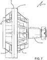
- Housing 12 is formed from two main pieces - a first housing portion 14 that is capable of receiving a second housing portion 16 - that can be secured in respective position with each other using one or more fasteners, such as bolt 17 and nut 19 ( Fig. 7 ).
- second portion 16 includes a protrusion that fits into a bore of first portion 14.
- First housing portion 14 which can also be described as a power plate 14, houses a spring applied, hydraulically released (SAHR) assembly, which includes a piston 18 and a plurality of springs 20 capable of acting on piston 18.
- Piston 18 includes a body portion 22 including one or more spring housings 24 to receive springs 20 therein.
- Spring housing 24 can also be described as a cutout 24 formed in piston 18.
- a first end of each spring 20 engages piston 18 and a second end of each spring 20 engages first housing portion 14.
- springs 20 cause piston 18 to engage a disc stack to thereby enact a braking function.
- Piston 18 is specifically housed in a piston bore 26 of first portion 14.
- Piston body portion 22 includes an outer cylindrical surface 28 that engages the chamber formed by piston bore 26.
- Outer cylindrical surface 28 may include a sealing ring, such as a combination of O-ring 30A and backup ring 30B, to allow a small clearance between outer cylindrical surface 28 and bore 26 while still preventing fluid from leaking past this seal.
- First housing portion 14 further includes a pilot bore 32 for receiving a component of second housing portion 16.
- second housing portion 16 includes a body portion 34 with a projecting flange 36 extending therefrom toward first portion 14.
- Projecting flange 36 includes an outer cylindrical surface 38 that engages the chamber formed by pilot bore 32.
- Outer cylindrical surface 38 may include a sealing ring, such as a combination of O-ring 40A and back up ring 40B, to allow a small clearance between outer cylindrical surface 38 and bore 32 while still preventing fluid from leaking past this seal.
- First housing portion 14 also includes a relief bore 41 between piston bore 26 and pilot bore 32.
- Piston bore 26 and pilot bore 32 have a similar, or substantially similar, bore diameters, and the relief bore 41 has a slightly larger bore diameter than piston bore 26 and pilot bore 32.
- piston bore 26 and pilot bore 32 may be machined in the same machining step, with relief bore 41 being subsequently machined.
- relief bore 41 may include rounded lips 42, which prevent O-ring 30A from traveling across a sharp corner.
- Relief bore 41 also generally does not require the same fine surface finish as piston bore 26 and pilot bore 32 because it is not being used as a sealing surface. That is, sealing surfaces are generally those surfaces needing a fine surface finish such that an O-ring is not damaged or worn as it slides across the surface.
- Pilot projecting flange 36 includes an inner cylindrical surface 44 that engages a projecting flange 46 extending from body portion 22 of piston 18 toward second portion 16. More specifically, inner cylindrical surface 44 engages an outer cylindrical surface 48 of piston projecting flange 46.
- Outer cylindrical surface 48 may include a sealing ring, such as a combination of O-ring 50A and back up ring 50B, to allow a small clearance between outer cylindrical surface 48 and inner cylindrical surface 44 while preventing fluid from leaking past this seal.
- the "default" position of piston 18 allows springs 20 to cause projecting flange 46 to engage a disc stack, generally indicated by the numeral 52, to thereby enact a braking function.
- projecting flange 46 engages a proximate, or inboard, stationary disc 54A of disc stack 52.
- the spring force of springs 20 must be selectively overcome in order to move piston 18 to an unactuated position to disengage disc stack 52.
- a hydraulic fluid supply network generally indicated by the numeral 56 ( Fig. 4 ), provides pressurized fluid to a fluid chamber 58.
- Fluid chamber 58 is in the general position of relief bore 41.
- piston 18 can be said to be in fluid communication with a source of hydraulic fluid.
- the hydraulic fluid fluidly engages piston 18 as to apply force against springs 20.
- the "default" position of piston 18 is as shown in Fig. 14 .
- Projecting flange 46 is engaging inboard stationary disc 54A, as shown at the numeral 55.
- a spacing 57 is provided between body portion 22 of piston 18 and first housing portion 14.
- hydraulic fluid is allowed to enter into fluid chamber 58 through hydraulic port 60.
- piston 18 travels against springs 20 until projecting flange 46 disengages inboard stationary disc 54A, thereby releasing disc stack 52.
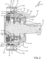
- Fig. 2 shows piston 18 being disengaged from inboard stationary disc 54A, creating a spacing 59 between projecting flange 46 of piston 18 and inboard stationary disc 54A.
- Disc stack 52 includes alternating stationary discs 54A, 54B, 54C and rotating discs 62A, 62B.
- Rotating discs are attached to a central, rotating shaft 64 such as by a spline and groove mechanism.
- shaft 64 can include ridges 66 that mate with grooves 68 in rotating discs 62A, 62B.
- ridges 70 in rotating discs 62A, 62B mate with grooves 72 in shaft 64.
- this spline and groove mechanism utilizes an involute spline.
- Other techniques for driving discs 62A, 62B utilizing shaft 64 may also be known to those skilled in the art.
- Each stationary disc 54A, 54B, 54C includes an ear 74 positioned between at least two torque pin grooves 76.
- Ear 74 is an extension from stationary discs 54A, 54B, 54C and can be generally semi-circular in shape.
- ear 74 is shaped with an angular portion 75 extending from each torque pin groove 76 to a linear portion 77, as shown in Fig. 8 .
- Each ear 74 is capable of fitting into a relief 78 ( Fig. 10 ) machined in second housing portion 16.
- relief 78 is shaped as a semi-circular cutaway from second housing portion 16.
- relief 78 can have a shape other than a semi-circle, such as rectangular, semi-oval, and other such shapes generally known to those skilled in the art.
- Relief 78 should be shaped similar to ear 74 as to receive and secure ear 74 therein.
- At least two torque pin holes 80 are also machined in second housing portion 16, with torque pin holes 80 being adapted to each receive a torque pin 82 ( Fig. 3 ).
- torque pin holes 80 do not extend to first housing portion 14; thus, first housing portion 14 can be said to be devoid of torque pin holes 80.
- torque pins 82 extend at least from inboard stationary disc 54A to outboard stationary disc 54C as to secure each stationary disc in place.
- Torque pin holes 80 extend at least from inboard stationary disc 54A to a distal end 83 of second housing assembly 16.
- Brake 10 may be built with distal end 83 positioned downward.
- Stationary disc 54C may be first inserted in second housing portion 16, then rotating disc 62B, then stationary disc 54B, then rotating disc 62A, then stationary discs 54A, to achieve the assembly arrangement shown in Fig. 2 . Then, torque pins 82 may be inserted into torque pin holes 80.
- each torque pin hole 80 supports the torque pin 82 therein along the entire length of the pin 82. This is in contrast to certain prior art brakes where torque pins are only supported at the ends of each pin.
- Each torque pin hole 80 forms a full throughbore where a corresponding pin 82 is inserted.
- plug 84 is added behind each torque pin 82.
- Plug 84 is placed into the portion of torque pin hole 80 behind the torque pin 82 to keep torque pin 82 in place.
- plug 84 is a freeze plug, and in other embodiments, plug 84 can be a pipe plug. Plug 84 also prevents outside contaminants, including water, from entering brake 10.
- one or more embodiments of the present invention include a metal support 86 inserted between stationary discs 54A, 54B, 54C and housing portion 16.
- Metal support 86 can be inserted opposite, or approximate thereto, relief 78 and prevents stationary discs 54A, 54B, 54C from contacting the housing.
- one or more embodiments of the present invention include a second relief 78B positioned 90 degrees, or approximate thereto, from the first relief 78.
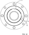
- stationary discs 54A, 54B, 54C include a second ear 74B that is positioned in second relief 78B, and second housing portion 16 includes additional torque pin holes 80 for receiving additional torque pins 82.
- one or more embodiments of the present invention include a second relief 78C positioned opposite, or approximate thereto, from the first relief 78.
- stationary discs 54A, 54B, 54C include a second ear 74C that is positioned in second relief 78C, and second housing portion 16 includes additional torque pin holes 80 for receiving additional torque pins 82.
- Brake 10 can be sized as to fit a number of applications and vehicle sizes. Brake 10 can also be characterized by the available hydraulic force and the predetermined spring force of springs 20. In one or more embodiments, the hydraulic force available behind piston 18 is in the range of from 1000 psi to 4000 psi. In one or more embodiments, the predetermined spring clamp force of springs 20 is in the range of from 2000 Ibf to 5500 Ibf. In one or more embodiments, the hydraulic force and spring clamp force can each be adjusted to account for vehicle size, speed, and environment. determine the necessary clamp force. Similarly, in one or more embodiments, the necessary release pressure can be determined by what is available on the vehicle where the brake is used, and, as such, the brake 10 can be adjusted for a variety of vehicles.
- Brake 10 is shown as a dry brake, but brake 10 could also be a wet brake as would be appreciated by one skilled in the art. Dry brakes experience wear directly on the friction material of the discs whereas wet brakes experience wear in the breakdown of oil in an oil sump within the brake.
- Brake 10 can be made using an aluminum die cast. Using a die cast process, minimal machining is required to produce a finished brake 10. This lowers the amount of machining time, tool wear, and scrap. Using an aluminum die cast offers an improvement over sand cast iron components.
- hydraulic fluid is initiated into fluid chamber 58. Hydraulic fluid fills fluid chamber 58 and begins to increase in pressure. Once sufficient hydraulic fluid pressure is supplied to fluid chamber 58, piston 18 is able to overcome the spring force of springs 20, thereby allowing piston 18 to travel away from disc stack 52. Once piston 18 disengages disc stack 52, rotating discs 62A, 62B are able to rotate freely with central shaft 64.
- brake 10 can be re-engaged when desired. Once the operator or other vehicle conditions requires that brake 10 be re-engaged, the pressure of the hydraulic fluid is allowed to release to "zero" such that springs 20 act to re-engage piston 18 with disc stack 52.
Landscapes
- Engineering & Computer Science (AREA)
- General Engineering & Computer Science (AREA)
- Mechanical Engineering (AREA)
- Braking Arrangements (AREA)
Description
- This invention relates to a spring applied, hydraulically released brake. More particularly, this invention relates to a spring applied, hydraulically released brake that includes an improved stationary disc support.
- Document
US 7 909 147 B1 discloses a brake comprising a first housing portion, a second housing portion and an alternating arrangement of stationary discs and rotating discs in said second housing portion. - Scissor lift and telehandler vehicles are known to use spring applied, hydraulically released brakes as a parking brake. These vehicles generally use multi-disc parking brakes located at the wheels of the vehicle. These brakes generally utilize hydraulic fluid to create hydraulic pressure in order to release the brake. The source of this hydraulic pressure is usually from vehicle hydraulics, since these vehicles generally include a hydraulic system. Brakes for these vehicles are generally built using several sand cast iron components, which are then machined to a finished state. This is expensive and inefficient. Brakes for these vehicles also must be compact with regard to space as available space for the brakes is limited. When considering replacement brakes for these vehicles, the available space cannot be changed or increased.
- Thus, there is a need for a brake that offers one or more improvements over the prior art, such as optimization of available space within a brake housing and a reduction of materials over known brakes.
- It is thus an object of one aspect of the present invention to provide a spring applied, hydraulically released brake that reduces machining operations by using near net shape die cast components, requiring minimal capital investment.
- It is an object of another aspect of the present invention to provide a brake, as above, where the stationary discs thereof are supported within the brake in a more compact and effective manner, easing assembly.
- It is an object of a further aspect of the present invention to provide a brake, as above, that can be installed in a like-for-like manner in the place of certain prior art brakes.
- These and other objects of the present invention, as well as the advantages thereof over existing prior art forms, which will become apparent from the description to follow, are accomplished by the improvements hereinafter described and claimed.
- In general, a brake made in accordance with the present invention includes a first housing portion and a second housing portion, the second housing portion having a distal end. An alternating arrangement of stationary and rotating discs are in the second housing portion. The stationary discs include an inboard stationary disc. At least two torque pin holes extend from the inboard stationary disc to the distal end of the second housing portion. Each of said stationary discs including an ear extending between two torque pin grooves. A torque pin is positioned in each of said torque pin holes and the torque pin grooves to thereby secure said stationary discs in a stationary position with respect to said second housing portion.
- In a preferred embodiment of the invention the brake includes a relief that is positioned in the second housing portion and is capable of receiving each ear therein.
- A preferred exemplary brake according to the concepts of the present invention is shown by way of example in the accompanying drawings without attempting to show all the various forms and modifications in which the invention might be embodied, the invention being measured by the appended claims and not by the details of the specification.
-
-
Fig. 1 is an elevational view of a brake according to the concepts of the present invention. -
Fig. 2 is a sectional view taken substantially along line A-A ofFig. 1 , showing the brake in a released position. -
Fig. 3 is a sectional view of a torque pin taken substantially along line C-C ofFig. 1 . -
Fig. 4 is a sectional view of a hydraulic fluid port taken substantially along line D-D ofFig. 1 . -
Fig. 5 is a sectional view of a bolt for securing a first housing portion with a second housing portion taken substantially along line E-E ofFig. 1 . -
Fig. 6 is an elevational view of a plurality of springs. -
Fig. 7 is a side elevational view of a brake according to the concepts of the present invention. -
Fig. 8 is an elevational view of a stationary disc. -
Fig. 9 is a perspective view showing a stationary disc in position in a brake. -
Fig. 10 is a partial perspective view of a second housing portion showing the torque pin holes and stationary disc ear relief. -
Fig. 11 is an elevation view showing an embodiment of a stationary disc in position in a brake, with a support component also positioned therein. -
Fig. 12 is an elevation view showing another embodiment of a stationary disc in position in a brake. -
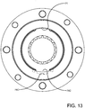
Fig. 13 is an elevation view showing another embodiment of a stationary disc in position in a brake. -
Fig. 14 is a sectional view taken substantially along line A-A ofFig. 1 , showing the brake in a default or engaged position. - A brake according to the concepts of the present invention is generally indicated by the
numeral 10.Brake 10 includes a housing, generally indicated by thenumeral 12, which carries and protects components ofbrake 10 and locates it in operative relation to a conventional wheel.Housing 12 is formed from two main pieces - afirst housing portion 14 that is capable of receiving a second housing portion 16 - that can be secured in respective position with each other using one or more fasteners, such asbolt 17 and nut 19 (Fig. 7 ). As will be described further herein,second portion 16 includes a protrusion that fits into a bore offirst portion 14. -
First housing portion 14, which can also be described as apower plate 14, houses a spring applied, hydraulically released (SAHR) assembly, which includes apiston 18 and a plurality ofsprings 20 capable of acting onpiston 18. Piston 18 includes abody portion 22 including one ormore spring housings 24 to receivesprings 20 therein.Spring housing 24 can also be described as acutout 24 formed inpiston 18. A first end of eachspring 20 engagespiston 18 and a second end of eachspring 20 engagesfirst housing portion 14. As will be described further herein, in a "default" position,springs 20cause piston 18 to engage a disc stack to thereby enact a braking function. - Piston 18 is specifically housed in a
piston bore 26 offirst portion 14. Pistonbody portion 22 includes an outercylindrical surface 28 that engages the chamber formed bypiston bore 26. Outercylindrical surface 28 may include a sealing ring, such as a combination of O-ring 30A andbackup ring 30B, to allow a small clearance between outercylindrical surface 28 and bore 26 while still preventing fluid from leaking past this seal. -
First housing portion 14 further includes apilot bore 32 for receiving a component ofsecond housing portion 16. Specifically,second housing portion 16 includes abody portion 34 with a projectingflange 36 extending therefrom towardfirst portion 14. Projectingflange 36 includes an outercylindrical surface 38 that engages the chamber formed bypilot bore 32. Outercylindrical surface 38 may include a sealing ring, such as a combination of O-ring 40A and back upring 40B, to allow a small clearance between outercylindrical surface 38 and bore 32 while still preventing fluid from leaking past this seal. -
First housing portion 14 also includes arelief bore 41 betweenpiston bore 26 and pilot bore 32. Piston bore 26 andpilot bore 32 have a similar, or substantially similar, bore diameters, and therelief bore 41 has a slightly larger bore diameter thanpiston bore 26 and pilot bore 32. Thus, piston bore 26 andpilot bore 32 may be machined in the same machining step, withrelief bore 41 being subsequently machined. Notably,relief bore 41 may includerounded lips 42, which prevent O-ring 30A from traveling across a sharp corner.Relief bore 41 also generally does not require the same fine surface finish as piston bore 26 and pilot bore 32 because it is not being used as a sealing surface. That is, sealing surfaces are generally those surfaces needing a fine surface finish such that an O-ring is not damaged or worn as it slides across the surface. The rougher the finish, the more wear occurs on an O-ring. A finer surface finish is also less likely to leak due to the peaks and valleys of a rougher surface finish. With respect to thepresent brake 10, since bore 41 is not a sealing surface, it is not going to wear the O-ring or cause leaks.Bore 41 androunded lips 42 may be subjected to some amount of surface finish to ensure there is no wear or snags on O-ring 30A during assembly ofpiston 18 inbrake 10. -
Pilot projecting flange 36 includes an innercylindrical surface 44 that engages a projectingflange 46 extending frombody portion 22 ofpiston 18 towardsecond portion 16. More specifically, innercylindrical surface 44 engages an outercylindrical surface 48 ofpiston projecting flange 46. Outercylindrical surface 48 may include a sealing ring, such as a combination of O-ring 50A and back upring 50B, to allow a small clearance between outercylindrical surface 48 and innercylindrical surface 44 while preventing fluid from leaking past this seal. - As previously described, the "default" position of
piston 18 allowssprings 20 to cause projectingflange 46 to engage a disc stack, generally indicated by the numeral 52, to thereby enact a braking function. Particularly, projectingflange 46 engages a proximate, or inboard,stationary disc 54A ofdisc stack 52. Thus, the spring force ofsprings 20 must be selectively overcome in order to movepiston 18 to an unactuated position to disengagedisc stack 52. - To accomplish this, a hydraulic fluid supply network, generally indicated by the numeral 56 (
Fig. 4 ), provides pressurized fluid to afluid chamber 58.Fluid chamber 58 is in the general position of relief bore 41. By way offluid chamber 58,piston 18 can be said to be in fluid communication with a source of hydraulic fluid. Upon adding hydraulic fluid tofluid chamber 58, the hydraulic fluid fluidly engagespiston 18 as to apply force against springs 20. - The "default" position of
piston 18 is as shown inFig. 14 . Projectingflange 46 is engaging inboardstationary disc 54A, as shown at the numeral 55. A spacing 57 is provided betweenbody portion 22 ofpiston 18 andfirst housing portion 14. To movepiston 18 from the default position, hydraulic fluid is allowed to enter intofluid chamber 58 throughhydraulic port 60. Once the pressure of the hydraulic fluid behindpiston 18 is sufficient to overcome the spring force ofsprings 20,piston 18 travels againstsprings 20 until projectingflange 46 disengages inboardstationary disc 54A, thereby releasingdisc stack 52.Fig. 2 showspiston 18 being disengaged from inboardstationary disc 54A, creating aspacing 59 between projectingflange 46 ofpiston 18 and inboardstationary disc 54A. - The engaging and releasing of
disc stack 52 will now be further described.Disc stack 52 includes alternatingstationary discs rotating discs rotating shaft 64 such as by a spline and groove mechanism. For example, with reference toFig. 9 ,shaft 64 can includeridges 66 that mate withgrooves 68 inrotating discs ridges 70 inrotating discs grooves 72 inshaft 64. In one or more embodiments, this spline and groove mechanism utilizes an involute spline. Other techniques for drivingdiscs 62B utilizing shaft 64 may also be known to those skilled in the art. - While
rotating discs shaft 64,stationary discs stationary disc ear 74 positioned between at least twotorque pin grooves 76.Ear 74 is an extension fromstationary discs ear 74 is shaped with anangular portion 75 extending from eachtorque pin groove 76 to alinear portion 77, as shown inFig. 8 . Eachear 74 is capable of fitting into a relief 78 (Fig. 10 ) machined insecond housing portion 16. In one or more embodiments,relief 78 is shaped as a semi-circular cutaway fromsecond housing portion 16. In other embodiments,relief 78 can have a shape other than a semi-circle, such as rectangular, semi-oval, and other such shapes generally known to those skilled in the art.Relief 78 should be shaped similar toear 74 as to receive andsecure ear 74 therein. - At least two torque pin holes 80 are also machined in
second housing portion 16, with torque pin holes 80 being adapted to each receive a torque pin 82 (Fig. 3 ). Thus, whenear 74 is inrelief 78 and torque pins 82 are in torque pin holes 80,stationary discs first housing portion 14; thus,first housing portion 14 can be said to be devoid of torque pin holes 80. - It should be appreciated that torque pins 82 extend at least from inboard
stationary disc 54A to outboardstationary disc 54C as to secure each stationary disc in place. Torque pin holes 80 extend at least from inboardstationary disc 54A to adistal end 83 ofsecond housing assembly 16. For assemblingdisc stack 52, the alternating arrangement of discs, best seen inFig. 2 , is positioned intosecond housing portion 16.Brake 10 may be built withdistal end 83 positioned downward.Stationary disc 54C may be first inserted insecond housing portion 16, then rotatingdisc 62B, thenstationary disc 54B, then rotatingdisc 62A, thenstationary discs 54A, to achieve the assembly arrangement shown inFig. 2 . Then, torque pins 82 may be inserted into torque pin holes 80. It should be appreciated that eachtorque pin hole 80 supports thetorque pin 82 therein along the entire length of thepin 82. This is in contrast to certain prior art brakes where torque pins are only supported at the ends of each pin. Eachtorque pin hole 80 forms a full throughbore where acorresponding pin 82 is inserted. Oncedisc stack 52 and torque pins 82 are positioned insecond housing portion 16,second housing portion 16 andfirst housing portion 14 may be brought together, as shown inFig. 2 . - To secure torque pins 82 in place, a plug 84, or other insertion, is added behind each
torque pin 82. Plug 84 is placed into the portion oftorque pin hole 80 behind thetorque pin 82 to keeptorque pin 82 in place. In one or more embodiments, plug 84 is a freeze plug, and in other embodiments, plug 84 can be a pipe plug. Plug 84 also prevents outside contaminants, including water, from enteringbrake 10. - As shown in
Fig. 11 , one or more embodiments of the present invention include ametal support 86 inserted betweenstationary discs housing portion 16.Metal support 86 can be inserted opposite, or approximate thereto,relief 78 and preventsstationary discs - As shown in
Fig. 12 , one or more embodiments of the present invention include asecond relief 78B positioned 90 degrees, or approximate thereto, from thefirst relief 78. In these embodiments,stationary discs second ear 74B that is positioned insecond relief 78B, andsecond housing portion 16 includes additional torque pin holes 80 for receiving additional torque pins 82. - As shown in
Fig. 13 , one or more embodiments of the present invention include asecond relief 78C positioned opposite, or approximate thereto, from thefirst relief 78. In these embodiments,stationary discs second ear 74C that is positioned insecond relief 78C, andsecond housing portion 16 includes additional torque pin holes 80 for receiving additional torque pins 82. - Again, in the "default" position of
piston 18, springs 20cause projecting flange 46 to engagedisc stack 52. This clamps togetherdisc stack 52 as to clamprotating discs stationary discs rotating discs disc stack 52 is that which resists the torque on the wheel of a vehicle. In one or more embodiments, rotatingdiscs stationary discs stationary discs rotating discs stationary discs rotating discs - As previously discussed, this braking position is maintained until the pressure of the hydraulic fluid behind
piston 18 is sufficient to overcome the spring force ofsprings 20. This then movespiston 18 away fromdisc stack 52 thereby allowingrotating discs central shaft 64.Brake 10 is now disengaged and the associated vehicle is able to move.Brake 10 is disengaged until the hydraulic pressure is allowed to drop as to cause piston to re-engagedisc stack 52. If the associated vehicle is turned off or has a hydraulic system failure, hydraulic pressure behindpiston 18 returns to zero. -
Brake 10 can be sized as to fit a number of applications and vehicle sizes.Brake 10 can also be characterized by the available hydraulic force and the predetermined spring force ofsprings 20. In one or more embodiments, the hydraulic force available behindpiston 18 is in the range of from 1000 psi to 4000 psi. In one or more embodiments, the predetermined spring clamp force ofsprings 20 is in the range of from 2000 Ibf to 5500 Ibf. In one or more embodiments, the hydraulic force and spring clamp force can each be adjusted to account for vehicle size, speed, and environment. determine the necessary clamp force. Similarly, in one or more embodiments, the necessary release pressure can be determined by what is available on the vehicle where the brake is used, and, as such, thebrake 10 can be adjusted for a variety of vehicles. -
Brake 10 is shown as a dry brake, butbrake 10 could also be a wet brake as would be appreciated by one skilled in the art. Dry brakes experience wear directly on the friction material of the discs whereas wet brakes experience wear in the breakdown of oil in an oil sump within the brake. -
Brake 10 can be made using an aluminum die cast. Using a die cast process, minimal machining is required to produce afinished brake 10. This lowers the amount of machining time, tool wear, and scrap. Using an aluminum die cast offers an improvement over sand cast iron components. -
Brake 10 is designed to be used on a scissor lift or a telehandler vehicle, but could be used in any suitable vehicle.Brake 10 is particularly envisioned as being mounted to the wheel end of such a vehicle, though other suitable mounting locations are possible. - As described above, in operation of
brake 10, hydraulic fluid is initiated intofluid chamber 58. Hydraulic fluid fillsfluid chamber 58 and begins to increase in pressure. Once sufficient hydraulic fluid pressure is supplied tofluid chamber 58,piston 18 is able to overcome the spring force ofsprings 20, thereby allowingpiston 18 to travel away fromdisc stack 52. Oncepiston 18disengages disc stack 52, rotatingdiscs central shaft 64. - After
piston 18 overcomes the spring force ofsprings 20 to disengagebrake 10,brake 10 can be re-engaged when desired. Once the operator or other vehicle conditions requires thatbrake 10 be re-engaged, the pressure of the hydraulic fluid is allowed to release to "zero" such that springs 20 act to re-engagepiston 18 withdisc stack 52. - It is thus evident that a brake constructed as described herein accomplishes the objects of the present invention and otherwise substantially improves the art.
Claims (10)
- A brake (10) comprising a first housing portion (14), a second housing portion (16) having a distal end (83), an alternating arrangement of stationary discs (54A,B,C) and rotating discs (62A,B) in said second housing portion (16), said stationary discs (54A,B,C) including an inboard stationary disc (54A), characterised in that said brake further comprises at least two torque pin holes (80) extending from said inboard stationary disc (54A) to said distal end (83) of said second housing portion (16), each of said stationary discs (54A,B,C) including an ear (74) extending between two torque pin grooves (76), and a torque pin (82) positioned in each of said torque pin holes (80) and the torque pin grooves (76) to thereby secure said stationary discs (54A,B,C) in a stationary position with respect to said second housing portion (16).
- The brake of claim 1, further comprising a plug (84) positioned in each of said torque pin holes (80) to thereby secure said torque pins (84) in a fixed position.
- The brake of claim 1, further comprising a piston (18) in said first housing portion (14), said piston (18) having a body portion (22) housing a plurality of springs (20) therein, and a fluid chamber for receiving hydraulic fluid therein, said fluid chamber being in fluid communication with said piston (18).
- The brake of claim 3, said piston (18) having a projecting flange (46) extending from said body portion (22), said projecting flange (46) engaging said inboard stationary disc (54A) to thereby enact a braking function on said alternating arrangement of discs (52).
- The brake of claim 4, wherein said piston (18) is urged against said springs (20) when said fluid chamber is pressurized with hydraulic fluid to thereby cause said projecting flange (46) to disengage said inboard stationary disc (54A) to thereby allow said rotating discs (62A,B) to rotate.
- The brake of claim 1, the brake further comprising a relief (78) in said second housing portion (16), said relief (78) being capable of receiving each ear (74) therein.
- The brake of claim 6, wherein each of said ears (74) is generally semi-circular shaped.
- The brake of claim 6, wherein each of said stationary discs (54A,B,C) includes a second ear (74B) positioned approximately 90 degrees from said first ear.
- The brake of claim 6, the ear (74) is shaped with an angular portion (75) extending from each torque pin groove (76) to a linear portion (77).
- The brake of claim 1, or claim 6, in which the brake has only two torque pin holes (80).
Applications Claiming Priority (2)
| Application Number | Priority Date | Filing Date | Title |
|---|---|---|---|
| US201662337957P | 2016-05-18 | 2016-05-18 | |
| US15/587,962 US10174798B2 (en) | 2016-05-18 | 2017-05-05 | Spring applied, hydraulically released wheel-mount brake having improved stationary disc support |
Publications (3)
| Publication Number | Publication Date |
|---|---|
| EP3267066A2 EP3267066A2 (en) | 2018-01-10 |
| EP3267066A3 EP3267066A3 (en) | 2018-03-21 |
| EP3267066B1 true EP3267066B1 (en) | 2020-03-04 |
Family
ID=60330499
Family Applications (1)
| Application Number | Title | Priority Date | Filing Date |
|---|---|---|---|
| EP17171670.7A Active EP3267066B1 (en) | 2016-05-18 | 2017-05-18 | Spring applied, hydraulically released wheel-mount brake having improved stationary disc support |
Country Status (2)
| Country | Link |
|---|---|
| US (1) | US10174798B2 (en) |
| EP (1) | EP3267066B1 (en) |
Families Citing this family (5)
| Publication number | Priority date | Publication date | Assignee | Title |
|---|---|---|---|---|
| JP7040105B2 (en) | 2018-02-20 | 2022-03-23 | マツダ株式会社 | Automatic transmission |
| JP2019143707A (en) * | 2018-02-20 | 2019-08-29 | マツダ株式会社 | Automatic transmission |
| KR102204628B1 (en) * | 2018-12-19 | 2021-01-19 | 주식회사 모트롤 | Brake spring fixing device |
| DE102019117929A1 (en) * | 2019-07-03 | 2021-01-07 | Gustav Magenwirth Gmbh & Co. Kg | Brake system with parking brake device |
| DE202023102323U1 (en) * | 2023-04-28 | 2024-07-30 | Hanning & Kahl Gmbh & Co. Kg | Spring brake actuator |
Family Cites Families (4)
| Publication number | Priority date | Publication date | Assignee | Title |
|---|---|---|---|---|
| US4263991A (en) * | 1977-05-27 | 1981-04-28 | Lambert Brake Company | Combined failsafe and service brake |
| DE60123010T2 (en) | 2001-02-23 | 2007-04-19 | Dana Italia S.P.A., Arco | Wheel hub with integrated planetary gear and multi-disc brake |
| US7353921B2 (en) | 2005-08-25 | 2008-04-08 | Ausco Products, Inc. | Self aligning brake kit |
| US7909147B1 (en) | 2007-02-14 | 2011-03-22 | Ausco Products, Inc. | Low drag failsafe brake |
-
2017
- 2017-05-05 US US15/587,962 patent/US10174798B2/en active Active
- 2017-05-18 EP EP17171670.7A patent/EP3267066B1/en active Active
Non-Patent Citations (1)
| Title |
|---|
| None * |
Also Published As
| Publication number | Publication date |
|---|---|
| US10174798B2 (en) | 2019-01-08 |
| US20170335909A1 (en) | 2017-11-23 |
| EP3267066A2 (en) | 2018-01-10 |
| EP3267066A3 (en) | 2018-03-21 |
Similar Documents
| Publication | Publication Date | Title |
|---|---|---|
| US10174798B2 (en) | Spring applied, hydraulically released wheel-mount brake having improved stationary disc support | |
| EP2020524B1 (en) | Caliper brake system | |
| US8257070B2 (en) | Seal apparatus of gear pump | |
| US8663058B2 (en) | Brake assembly having piloted park brake housing | |
| GB1573292A (en) | Caliper type disc brake | |
| JPS58139850A (en) | Hub | |
| US11156256B2 (en) | Hydraulic caliper assembly | |
| CN107956823B (en) | Exhaust valve for bicycle hydraulic brake system | |
| JPH02283559A (en) | Hydraulic actuator | |
| US20040216967A1 (en) | Caliper for a disc brake | |
| CN110720000B (en) | Clamp body and disc brake | |
| CA2967656A1 (en) | Spring applied, hydraulically released wheel-mount brake having improved stationary disc support | |
| EP0062403B1 (en) | Disc brake caliper | |
| US10006498B2 (en) | Drive assembly with bimodal clutch module | |
| US10436264B2 (en) | Spring applied, hydraulically released brake with manual override | |
| EP1917450B1 (en) | Self aligning brake kit | |
| US5466052A (en) | A fluid connecting device | |
| US10072683B1 (en) | Automatic transmission piston with supported servo pin | |
| US6899017B2 (en) | Wheel cylinder for actuating a vehicle brake and a method of manufacturing same | |
| US8250967B2 (en) | Automatic transmission servo | |
| EP3546785A2 (en) | Brake assembly | |
| JP7442620B2 (en) | Transport protection plug | |
| US9562580B1 (en) | Caliper brake having spring applied, hydraulically released assembly and pressure intensifying assembly | |
| US20240255039A1 (en) | Spring applied hydraulic release caliper brake and methods of adjustment | |
| USRE24652E (en) | Assembly for use as a clutch or a brake |
Legal Events
| Date | Code | Title | Description |
|---|---|---|---|
| PUAI | Public reference made under article 153(3) epc to a published international application that has entered the european phase |
Free format text: ORIGINAL CODE: 0009012 |
|
| STAA | Information on the status of an ep patent application or granted ep patent |
Free format text: STATUS: THE APPLICATION HAS BEEN PUBLISHED |
|
| AK | Designated contracting states |
Kind code of ref document: A2 Designated state(s): AL AT BE BG CH CY CZ DE DK EE ES FI FR GB GR HR HU IE IS IT LI LT LU LV MC MK MT NL NO PL PT RO RS SE SI SK SM TR |
|
| AX | Request for extension of the european patent |
Extension state: BA ME |
|
| PUAL | Search report despatched |
Free format text: ORIGINAL CODE: 0009013 |
|
| AK | Designated contracting states |
Kind code of ref document: A3 Designated state(s): AL AT BE BG CH CY CZ DE DK EE ES FI FR GB GR HR HU IE IS IT LI LT LU LV MC MK MT NL NO PL PT RO RS SE SI SK SM TR |
|
| AX | Request for extension of the european patent |
Extension state: BA ME |
|
| RIC1 | Information provided on ipc code assigned before grant |
Ipc: F16D 55/36 20060101ALI20180215BHEP Ipc: F16D 65/18 20060101AFI20180215BHEP |
|
| STAA | Information on the status of an ep patent application or granted ep patent |
Free format text: STATUS: REQUEST FOR EXAMINATION WAS MADE |
|
| 17P | Request for examination filed |
Effective date: 20180920 |
|
| RBV | Designated contracting states (corrected) |
Designated state(s): AL AT BE BG CH CY CZ DE DK EE ES FI FR GB GR HR HU IE IS IT LI LT LU LV MC MK MT NL NO PL PT RO RS SE SI SK SM TR |
|
| GRAP | Despatch of communication of intention to grant a patent |
Free format text: ORIGINAL CODE: EPIDOSNIGR1 |
|
| STAA | Information on the status of an ep patent application or granted ep patent |
Free format text: STATUS: GRANT OF PATENT IS INTENDED |
|
| INTG | Intention to grant announced |
Effective date: 20191004 |
|
| GRAS | Grant fee paid |
Free format text: ORIGINAL CODE: EPIDOSNIGR3 |
|
| GRAA | (expected) grant |
Free format text: ORIGINAL CODE: 0009210 |
|
| STAA | Information on the status of an ep patent application or granted ep patent |
Free format text: STATUS: THE PATENT HAS BEEN GRANTED |
|
| AK | Designated contracting states |
Kind code of ref document: B1 Designated state(s): AL AT BE BG CH CY CZ DE DK EE ES FI FR GB GR HR HU IE IS IT LI LT LU LV MC MK MT NL NO PL PT RO RS SE SI SK SM TR |
|
| REG | Reference to a national code |
Ref country code: GB Ref legal event code: FG4D |
|
| REG | Reference to a national code |
Ref country code: CH Ref legal event code: EP |
|
| REG | Reference to a national code |
Ref country code: AT Ref legal event code: REF Ref document number: 1240720 Country of ref document: AT Kind code of ref document: T Effective date: 20200315 |
|
| REG | Reference to a national code |
Ref country code: DE Ref legal event code: R096 Ref document number: 602017012465 Country of ref document: DE |
|
| REG | Reference to a national code |
Ref country code: IE Ref legal event code: FG4D |
|
| PG25 | Lapsed in a contracting state [announced via postgrant information from national office to epo] |
Ref country code: FI Free format text: LAPSE BECAUSE OF FAILURE TO SUBMIT A TRANSLATION OF THE DESCRIPTION OR TO PAY THE FEE WITHIN THE PRESCRIBED TIME-LIMIT Effective date: 20200304 Ref country code: RS Free format text: LAPSE BECAUSE OF FAILURE TO SUBMIT A TRANSLATION OF THE DESCRIPTION OR TO PAY THE FEE WITHIN THE PRESCRIBED TIME-LIMIT Effective date: 20200304 Ref country code: NO Free format text: LAPSE BECAUSE OF FAILURE TO SUBMIT A TRANSLATION OF THE DESCRIPTION OR TO PAY THE FEE WITHIN THE PRESCRIBED TIME-LIMIT Effective date: 20200604 |
|
| PGFP | Annual fee paid to national office [announced via postgrant information from national office to epo] |
Ref country code: FR Payment date: 20200414 Year of fee payment: 4 Ref country code: DE Payment date: 20200506 Year of fee payment: 4 |
|
| REG | Reference to a national code |
Ref country code: NL Ref legal event code: MP Effective date: 20200304 |
|
| PG25 | Lapsed in a contracting state [announced via postgrant information from national office to epo] |
Ref country code: HR Free format text: LAPSE BECAUSE OF FAILURE TO SUBMIT A TRANSLATION OF THE DESCRIPTION OR TO PAY THE FEE WITHIN THE PRESCRIBED TIME-LIMIT Effective date: 20200304 Ref country code: BG Free format text: LAPSE BECAUSE OF FAILURE TO SUBMIT A TRANSLATION OF THE DESCRIPTION OR TO PAY THE FEE WITHIN THE PRESCRIBED TIME-LIMIT Effective date: 20200604 Ref country code: LV Free format text: LAPSE BECAUSE OF FAILURE TO SUBMIT A TRANSLATION OF THE DESCRIPTION OR TO PAY THE FEE WITHIN THE PRESCRIBED TIME-LIMIT Effective date: 20200304 Ref country code: GR Free format text: LAPSE BECAUSE OF FAILURE TO SUBMIT A TRANSLATION OF THE DESCRIPTION OR TO PAY THE FEE WITHIN THE PRESCRIBED TIME-LIMIT Effective date: 20200605 Ref country code: SE Free format text: LAPSE BECAUSE OF FAILURE TO SUBMIT A TRANSLATION OF THE DESCRIPTION OR TO PAY THE FEE WITHIN THE PRESCRIBED TIME-LIMIT Effective date: 20200304 |
|
| REG | Reference to a national code |
Ref country code: LT Ref legal event code: MG4D |
|
| PG25 | Lapsed in a contracting state [announced via postgrant information from national office to epo] |
Ref country code: NL Free format text: LAPSE BECAUSE OF FAILURE TO SUBMIT A TRANSLATION OF THE DESCRIPTION OR TO PAY THE FEE WITHIN THE PRESCRIBED TIME-LIMIT Effective date: 20200304 |
|
| PG25 | Lapsed in a contracting state [announced via postgrant information from national office to epo] |
Ref country code: IS Free format text: LAPSE BECAUSE OF FAILURE TO SUBMIT A TRANSLATION OF THE DESCRIPTION OR TO PAY THE FEE WITHIN THE PRESCRIBED TIME-LIMIT Effective date: 20200704 Ref country code: CZ Free format text: LAPSE BECAUSE OF FAILURE TO SUBMIT A TRANSLATION OF THE DESCRIPTION OR TO PAY THE FEE WITHIN THE PRESCRIBED TIME-LIMIT Effective date: 20200304 Ref country code: RO Free format text: LAPSE BECAUSE OF FAILURE TO SUBMIT A TRANSLATION OF THE DESCRIPTION OR TO PAY THE FEE WITHIN THE PRESCRIBED TIME-LIMIT Effective date: 20200304 Ref country code: SK Free format text: LAPSE BECAUSE OF FAILURE TO SUBMIT A TRANSLATION OF THE DESCRIPTION OR TO PAY THE FEE WITHIN THE PRESCRIBED TIME-LIMIT Effective date: 20200304 Ref country code: ES Free format text: LAPSE BECAUSE OF FAILURE TO SUBMIT A TRANSLATION OF THE DESCRIPTION OR TO PAY THE FEE WITHIN THE PRESCRIBED TIME-LIMIT Effective date: 20200304 Ref country code: LT Free format text: LAPSE BECAUSE OF FAILURE TO SUBMIT A TRANSLATION OF THE DESCRIPTION OR TO PAY THE FEE WITHIN THE PRESCRIBED TIME-LIMIT Effective date: 20200304 Ref country code: EE Free format text: LAPSE BECAUSE OF FAILURE TO SUBMIT A TRANSLATION OF THE DESCRIPTION OR TO PAY THE FEE WITHIN THE PRESCRIBED TIME-LIMIT Effective date: 20200304 Ref country code: PT Free format text: LAPSE BECAUSE OF FAILURE TO SUBMIT A TRANSLATION OF THE DESCRIPTION OR TO PAY THE FEE WITHIN THE PRESCRIBED TIME-LIMIT Effective date: 20200729 Ref country code: SM Free format text: LAPSE BECAUSE OF FAILURE TO SUBMIT A TRANSLATION OF THE DESCRIPTION OR TO PAY THE FEE WITHIN THE PRESCRIBED TIME-LIMIT Effective date: 20200304 |
|
| REG | Reference to a national code |
Ref country code: AT Ref legal event code: MK05 Ref document number: 1240720 Country of ref document: AT Kind code of ref document: T Effective date: 20200304 |
|
| REG | Reference to a national code |
Ref country code: DE Ref legal event code: R097 Ref document number: 602017012465 Country of ref document: DE |
|
| PLBE | No opposition filed within time limit |
Free format text: ORIGINAL CODE: 0009261 |
|
| STAA | Information on the status of an ep patent application or granted ep patent |
Free format text: STATUS: NO OPPOSITION FILED WITHIN TIME LIMIT |
|
| PG25 | Lapsed in a contracting state [announced via postgrant information from national office to epo] |
Ref country code: DK Free format text: LAPSE BECAUSE OF FAILURE TO SUBMIT A TRANSLATION OF THE DESCRIPTION OR TO PAY THE FEE WITHIN THE PRESCRIBED TIME-LIMIT Effective date: 20200304 Ref country code: LI Free format text: LAPSE BECAUSE OF NON-PAYMENT OF DUE FEES Effective date: 20200531 Ref country code: MC Free format text: LAPSE BECAUSE OF FAILURE TO SUBMIT A TRANSLATION OF THE DESCRIPTION OR TO PAY THE FEE WITHIN THE PRESCRIBED TIME-LIMIT Effective date: 20200304 Ref country code: CH Free format text: LAPSE BECAUSE OF NON-PAYMENT OF DUE FEES Effective date: 20200531 Ref country code: IT Free format text: LAPSE BECAUSE OF FAILURE TO SUBMIT A TRANSLATION OF THE DESCRIPTION OR TO PAY THE FEE WITHIN THE PRESCRIBED TIME-LIMIT Effective date: 20200304 Ref country code: AT Free format text: LAPSE BECAUSE OF FAILURE TO SUBMIT A TRANSLATION OF THE DESCRIPTION OR TO PAY THE FEE WITHIN THE PRESCRIBED TIME-LIMIT Effective date: 20200304 |
|
| 26N | No opposition filed |
Effective date: 20201207 |
|
| PG25 | Lapsed in a contracting state [announced via postgrant information from national office to epo] |
Ref country code: PL Free format text: LAPSE BECAUSE OF FAILURE TO SUBMIT A TRANSLATION OF THE DESCRIPTION OR TO PAY THE FEE WITHIN THE PRESCRIBED TIME-LIMIT Effective date: 20200304 Ref country code: SI Free format text: LAPSE BECAUSE OF FAILURE TO SUBMIT A TRANSLATION OF THE DESCRIPTION OR TO PAY THE FEE WITHIN THE PRESCRIBED TIME-LIMIT Effective date: 20200304 |
|
| REG | Reference to a national code |
Ref country code: BE Ref legal event code: MM Effective date: 20200531 |
|
| PG25 | Lapsed in a contracting state [announced via postgrant information from national office to epo] |
Ref country code: LU Free format text: LAPSE BECAUSE OF NON-PAYMENT OF DUE FEES Effective date: 20200518 |
|
| PG25 | Lapsed in a contracting state [announced via postgrant information from national office to epo] |
Ref country code: IE Free format text: LAPSE BECAUSE OF NON-PAYMENT OF DUE FEES Effective date: 20200518 |
|
| PG25 | Lapsed in a contracting state [announced via postgrant information from national office to epo] |
Ref country code: BE Free format text: LAPSE BECAUSE OF NON-PAYMENT OF DUE FEES Effective date: 20200531 |
|
| REG | Reference to a national code |
Ref country code: DE Ref legal event code: R119 Ref document number: 602017012465 Country of ref document: DE |
|
| GBPC | Gb: european patent ceased through non-payment of renewal fee |
Effective date: 20210518 |
|
| PG25 | Lapsed in a contracting state [announced via postgrant information from national office to epo] |
Ref country code: GB Free format text: LAPSE BECAUSE OF NON-PAYMENT OF DUE FEES Effective date: 20210518 Ref country code: DE Free format text: LAPSE BECAUSE OF NON-PAYMENT OF DUE FEES Effective date: 20211201 |
|
| PG25 | Lapsed in a contracting state [announced via postgrant information from national office to epo] |
Ref country code: TR Free format text: LAPSE BECAUSE OF FAILURE TO SUBMIT A TRANSLATION OF THE DESCRIPTION OR TO PAY THE FEE WITHIN THE PRESCRIBED TIME-LIMIT Effective date: 20200304 Ref country code: MT Free format text: LAPSE BECAUSE OF FAILURE TO SUBMIT A TRANSLATION OF THE DESCRIPTION OR TO PAY THE FEE WITHIN THE PRESCRIBED TIME-LIMIT Effective date: 20200304 Ref country code: FR Free format text: LAPSE BECAUSE OF NON-PAYMENT OF DUE FEES Effective date: 20210531 Ref country code: CY Free format text: LAPSE BECAUSE OF FAILURE TO SUBMIT A TRANSLATION OF THE DESCRIPTION OR TO PAY THE FEE WITHIN THE PRESCRIBED TIME-LIMIT Effective date: 20200304 |
|
| PG25 | Lapsed in a contracting state [announced via postgrant information from national office to epo] |
Ref country code: MK Free format text: LAPSE BECAUSE OF FAILURE TO SUBMIT A TRANSLATION OF THE DESCRIPTION OR TO PAY THE FEE WITHIN THE PRESCRIBED TIME-LIMIT Effective date: 20200304 Ref country code: AL Free format text: LAPSE BECAUSE OF FAILURE TO SUBMIT A TRANSLATION OF THE DESCRIPTION OR TO PAY THE FEE WITHIN THE PRESCRIBED TIME-LIMIT Effective date: 20200304 |