EP3266987A1 - Turbine speed and acceleration limiter - Google Patents
Turbine speed and acceleration limiter Download PDFInfo
- Publication number
- EP3266987A1 EP3266987A1 EP16290133.4A EP16290133A EP3266987A1 EP 3266987 A1 EP3266987 A1 EP 3266987A1 EP 16290133 A EP16290133 A EP 16290133A EP 3266987 A1 EP3266987 A1 EP 3266987A1
- Authority
- EP
- European Patent Office
- Prior art keywords
- speed
- acceleration
- turbine
- steam
- threshold value
- Prior art date
- Legal status (The legal status is an assumption and is not a legal conclusion. Google has not performed a legal analysis and makes no representation as to the accuracy of the status listed.)
- Withdrawn
Links
Images

Classifications
-
- F—MECHANICAL ENGINEERING; LIGHTING; HEATING; WEAPONS; BLASTING
- F01—MACHINES OR ENGINES IN GENERAL; ENGINE PLANTS IN GENERAL; STEAM ENGINES
- F01K—STEAM ENGINE PLANTS; STEAM ACCUMULATORS; ENGINE PLANTS NOT OTHERWISE PROVIDED FOR; ENGINES USING SPECIAL WORKING FLUIDS OR CYCLES
- F01K7/00—Steam engine plants characterised by the use of specific types of engine; Plants or engines characterised by their use of special steam systems, cycles or processes; Control means specially adapted for such systems, cycles or processes; Use of withdrawn or exhaust steam for feed-water heating
- F01K7/16—Steam engine plants characterised by the use of specific types of engine; Plants or engines characterised by their use of special steam systems, cycles or processes; Control means specially adapted for such systems, cycles or processes; Use of withdrawn or exhaust steam for feed-water heating the engines being only of turbine type
- F01K7/26—Steam engine plants characterised by the use of specific types of engine; Plants or engines characterised by their use of special steam systems, cycles or processes; Control means specially adapted for such systems, cycles or processes; Use of withdrawn or exhaust steam for feed-water heating the engines being only of turbine type the turbines having inter-stage steam accumulation
- F01K7/28—Control means specially adapted therefor
-
- F—MECHANICAL ENGINEERING; LIGHTING; HEATING; WEAPONS; BLASTING
- F01—MACHINES OR ENGINES IN GENERAL; ENGINE PLANTS IN GENERAL; STEAM ENGINES
- F01D—NON-POSITIVE DISPLACEMENT MACHINES OR ENGINES, e.g. STEAM TURBINES
- F01D17/00—Regulating or controlling by varying flow
- F01D17/02—Arrangement of sensing elements
- F01D17/08—Arrangement of sensing elements responsive to condition of working-fluid, e.g. pressure
-
- F—MECHANICAL ENGINEERING; LIGHTING; HEATING; WEAPONS; BLASTING
- F01—MACHINES OR ENGINES IN GENERAL; ENGINE PLANTS IN GENERAL; STEAM ENGINES
- F01D—NON-POSITIVE DISPLACEMENT MACHINES OR ENGINES, e.g. STEAM TURBINES
- F01D21/00—Shutting-down of machines or engines, e.g. in emergency; Regulating, controlling, or safety means not otherwise provided for
- F01D21/02—Shutting-down responsive to overspeed
-
- F—MECHANICAL ENGINEERING; LIGHTING; HEATING; WEAPONS; BLASTING
- F01—MACHINES OR ENGINES IN GENERAL; ENGINE PLANTS IN GENERAL; STEAM ENGINES
- F01D—NON-POSITIVE DISPLACEMENT MACHINES OR ENGINES, e.g. STEAM TURBINES
- F01D21/00—Shutting-down of machines or engines, e.g. in emergency; Regulating, controlling, or safety means not otherwise provided for
- F01D21/12—Shutting-down of machines or engines, e.g. in emergency; Regulating, controlling, or safety means not otherwise provided for responsive to temperature
-
- F—MECHANICAL ENGINEERING; LIGHTING; HEATING; WEAPONS; BLASTING
- F01—MACHINES OR ENGINES IN GENERAL; ENGINE PLANTS IN GENERAL; STEAM ENGINES
- F01K—STEAM ENGINE PLANTS; STEAM ACCUMULATORS; ENGINE PLANTS NOT OTHERWISE PROVIDED FOR; ENGINES USING SPECIAL WORKING FLUIDS OR CYCLES
- F01K1/00—Steam accumulators
- F01K1/08—Charging or discharging of accumulators with steam
-
- F—MECHANICAL ENGINEERING; LIGHTING; HEATING; WEAPONS; BLASTING
- F01—MACHINES OR ENGINES IN GENERAL; ENGINE PLANTS IN GENERAL; STEAM ENGINES
- F01K—STEAM ENGINE PLANTS; STEAM ACCUMULATORS; ENGINE PLANTS NOT OTHERWISE PROVIDED FOR; ENGINES USING SPECIAL WORKING FLUIDS OR CYCLES
- F01K1/00—Steam accumulators
- F01K1/16—Other safety or control means
-
- F—MECHANICAL ENGINEERING; LIGHTING; HEATING; WEAPONS; BLASTING
- F01—MACHINES OR ENGINES IN GENERAL; ENGINE PLANTS IN GENERAL; STEAM ENGINES
- F01K—STEAM ENGINE PLANTS; STEAM ACCUMULATORS; ENGINE PLANTS NOT OTHERWISE PROVIDED FOR; ENGINES USING SPECIAL WORKING FLUIDS OR CYCLES
- F01K7/00—Steam engine plants characterised by the use of specific types of engine; Plants or engines characterised by their use of special steam systems, cycles or processes; Control means specially adapted for such systems, cycles or processes; Use of withdrawn or exhaust steam for feed-water heating
- F01K7/16—Steam engine plants characterised by the use of specific types of engine; Plants or engines characterised by their use of special steam systems, cycles or processes; Control means specially adapted for such systems, cycles or processes; Use of withdrawn or exhaust steam for feed-water heating the engines being only of turbine type
- F01K7/165—Controlling means specially adapted therefor
-
- F—MECHANICAL ENGINEERING; LIGHTING; HEATING; WEAPONS; BLASTING
- F01—MACHINES OR ENGINES IN GENERAL; ENGINE PLANTS IN GENERAL; STEAM ENGINES
- F01K—STEAM ENGINE PLANTS; STEAM ACCUMULATORS; ENGINE PLANTS NOT OTHERWISE PROVIDED FOR; ENGINES USING SPECIAL WORKING FLUIDS OR CYCLES
- F01K7/00—Steam engine plants characterised by the use of specific types of engine; Plants or engines characterised by their use of special steam systems, cycles or processes; Control means specially adapted for such systems, cycles or processes; Use of withdrawn or exhaust steam for feed-water heating
- F01K7/16—Steam engine plants characterised by the use of specific types of engine; Plants or engines characterised by their use of special steam systems, cycles or processes; Control means specially adapted for such systems, cycles or processes; Use of withdrawn or exhaust steam for feed-water heating the engines being only of turbine type
- F01K7/18—Steam engine plants characterised by the use of specific types of engine; Plants or engines characterised by their use of special steam systems, cycles or processes; Control means specially adapted for such systems, cycles or processes; Use of withdrawn or exhaust steam for feed-water heating the engines being only of turbine type the turbine being of multiple-inlet-pressure type
- F01K7/20—Control means specially adapted therefor
-
- F—MECHANICAL ENGINEERING; LIGHTING; HEATING; WEAPONS; BLASTING
- F01—MACHINES OR ENGINES IN GENERAL; ENGINE PLANTS IN GENERAL; STEAM ENGINES
- F01K—STEAM ENGINE PLANTS; STEAM ACCUMULATORS; ENGINE PLANTS NOT OTHERWISE PROVIDED FOR; ENGINES USING SPECIAL WORKING FLUIDS OR CYCLES
- F01K7/00—Steam engine plants characterised by the use of specific types of engine; Plants or engines characterised by their use of special steam systems, cycles or processes; Control means specially adapted for such systems, cycles or processes; Use of withdrawn or exhaust steam for feed-water heating
- F01K7/16—Steam engine plants characterised by the use of specific types of engine; Plants or engines characterised by their use of special steam systems, cycles or processes; Control means specially adapted for such systems, cycles or processes; Use of withdrawn or exhaust steam for feed-water heating the engines being only of turbine type
- F01K7/22—Steam engine plants characterised by the use of specific types of engine; Plants or engines characterised by their use of special steam systems, cycles or processes; Control means specially adapted for such systems, cycles or processes; Use of withdrawn or exhaust steam for feed-water heating the engines being only of turbine type the turbines having inter-stage steam heating
- F01K7/24—Control or safety means specially adapted therefor
-
- F—MECHANICAL ENGINEERING; LIGHTING; HEATING; WEAPONS; BLASTING
- F02—COMBUSTION ENGINES; HOT-GAS OR COMBUSTION-PRODUCT ENGINE PLANTS
- F02C—GAS-TURBINE PLANTS; AIR INTAKES FOR JET-PROPULSION PLANTS; CONTROLLING FUEL SUPPLY IN AIR-BREATHING JET-PROPULSION PLANTS
- F02C9/00—Controlling gas-turbine plants; Controlling fuel supply in air- breathing jet-propulsion plants
- F02C9/26—Control of fuel supply
- F02C9/28—Regulating systems responsive to plant or ambient parameters, e.g. temperature, pressure, rotor speed
-
- F—MECHANICAL ENGINEERING; LIGHTING; HEATING; WEAPONS; BLASTING
- F05—INDEXING SCHEMES RELATING TO ENGINES OR PUMPS IN VARIOUS SUBCLASSES OF CLASSES F01-F04
- F05D—INDEXING SCHEME FOR ASPECTS RELATING TO NON-POSITIVE-DISPLACEMENT MACHINES OR ENGINES, GAS-TURBINES OR JET-PROPULSION PLANTS
- F05D2220/00—Application
- F05D2220/30—Application in turbines
- F05D2220/31—Application in turbines in steam turbines
Definitions
- the present invention generally relates to power plant steam turbines and more particularly to a method for controlling steam admission into such a steam turbine.
- a power plant steam turbine is a device which converts thermal energy of pressurized steam to mechanical energy.
- the thermal energy is obtained by the production of steam by a boiler.
- the resulting steam flow is thus supplied to the steam turbine at the required pressure and temperature.
- the turbine converts the steam flow into a torque which is used for driving a rotor of an electric generator for the production of electrical energy.
- the rotor of the electric generator is driven by means of a turbine shaft that interconnects the rotor with the steam turbine.
- the electric generator is coupled with an alternating current electrical grid for distributing the produced electrical energy to the consumers through a plurality of transmission lines.
- an alternating current electrical grid for distributing the produced electrical energy to the consumers through a plurality of transmission lines.
- the electrical generator and the electrical grid are synchronized such that the frequency of the electrical generator matches the frequency of the electrical grid.
- the steam supplied by the boiler, enters a high pressure steam casing.
- the admission in the high pressure casing is done through stop valves and control valves.
- the steam After steam expansion in the high pressure casing, the steam is sent to moisture-separator reheaters pulling moisture and reheating the steam for preventing corrosion and erosion.
- the dried and reheated steam is thus admitted in a reduced pressure casing, which is generally an intermediate pressure steam casing, through intermediate pressure stop and control valves, and then admitted in one or more low pressure steam casings.
- a reduced pressure casing which is generally an intermediate pressure steam casing, through intermediate pressure stop and control valves, and then admitted in one or more low pressure steam casings.
- Certain steam turbines are not provided with intermediate pressure casing and the steam passes directly from the moisture-separator reheaters to the low pressure casings through low pressure stop and control valves.
- the turbine overspeed trip caused by the torque unbalance between the thermal power and the electrical load can lead to mechanical constraints on the shaft line and to an unavailability of the turbine-generator group.
- Another solution consists in sending closing and re-opening orders to the control valves.
- the disadvantage of this solution lies on the time to recover as well as the control valves stress.
- the present invention intends to overcome these disadvantages by providing a method for controlling admission steam into power plant steam turbine, the method being able to prevent an excessive speed and/or acceleration of the turbine which may lead to the turbine unavailability for the grid.
- the present invention thus proposes a method for controlling steam admission into a steam turbine, the turbine comprising a high pressure casing, at least one reduced pressure casing and an admission steam control system, the high pressure casing and at least one reduced pressure casing comprising control valves for steam admission.
- the steam admission control system manages the following steps: determining at least one of the speed and the acceleration of the turbine; comparing the determined speed and/or acceleration respectively with a predefined speed threshold value and a predefined acceleration threshold value; when the determined speed and/or acceleration are superior to the predefined threshold value, the control system activates a speed and acceleration limiter.
- the activated speed and acceleration limiter may impose control valve opening setpoints, depending on the determined speed and/or acceleration values, to the high pressure and reduced pressure control valves in order to regulate the steam admission into the turbine.
- the speed and acceleration limiter can act by a fast and appropriate response.
- control valve opening setpoints to the control valves may be performed through control valve position-loop cards.
- control valve opening setpoints may depend on the turbine steam flow demand.
- the steam flow demand is determined using parameters including at least one of the rotating speed of the turbine, the load, the live steam pressure and the turbine operating mode.
- the speed threshold value may be chosen according to the turbine nominal speed.
- the acceleration threshold value may be chosen according to the turbine maximum acceleration.
- the speed and acceleration limiter is deactivated when the turbine speed and acceleration drop below the threshold value since the situation is normalized.
- control system may be activated during a transient of the turbine during which an excessive speed and/or acceleration are the most likely to occur.
- Another object of the invention relates to a steam turbine comprising a high pressure casing, at least one reduced pressure casing and a steam admission control system, the high pressure casing and at least one reduced pressure casing comprising control valves for steam admission.
- the steam admission control system is configured to determine at least one of the speed and the acceleration of the turbine, compare the determined speed and/or acceleration respectively with a predefined speed threshold value and a predefined acceleration threshold value, and activate a speed and acceleration limiter when the determined speed and/or acceleration are superior to the threshold value
- hydraulic actuators are provided to perform the opening and closing of the control valves, the hydraulic actuators comprising an electro-hydraulic amplifier.
- hydraulic actuators are provided to perform the opening and the closing of the control valves, the hydraulic actuators comprising a hydraulic fast closing device for emergency closing of the associated control valves.
- a power plant steam turbine 1 comprises a high pressure steam casing 2 and at least on reduced pressure casings.
- the reduced pressure casings correspond to an intermediate steam casing 3 and three low pressure steam casings 4, 5 and 6.
- the steam turbine is also provided with stop valves 7 and control valves 8 upstream of the high pressure casing 2, and stop valves 9 and control valves 10 upstream of the intermediate pressure casing 3.
- Two moisture-separator reheaters 11 and 12 are located upstream of the intermediate pressure stop valves 9 and control valves 10.
- the steam supplied by a boiler (not shown here), enters the high pressure steam casing 2.
- the admission in the high pressure casing is done through high pressure stop valves 7 and high pressure control valves 8.
- the steam is thus admitted in the intermediate pressure casing 3, through the intermediate pressure stop valves 9 and the intermediate pressure control valves 10, and then admitted in the low pressure casings 4, 5 and 6.
- the steam turbine 1 comprises a steam admission control system 13 which, when the turbine is running and advantageously when a transient occurs, is activated.
- control system 13 determines one or both of the turbine speed 14 and the turbine acceleration 15.
- control system 13 compares the determined speed with a predefined speed threshold value 16 and compares the determined acceleration with a predefined acceleration threshold value 17.
- control system 13 activates a speed and acceleration limiter 20.
- the activated speed and acceleration limiter 20 imposes advantageously control valves opening setpoints 21, 22 to the high pressure control valves 8 and to the reduced pressure control valves which are, in that example, the intermediate pressure control valves 10.
- the control valves opening setpoints 21, 22 are preferably elaborated depending on the turbine steam flow demand 23.
- control system 13 may determine a steam flow demand 23 in function of various turbine parameters 24 and the determined speed and/or acceleration values.
- the parameters 24 may include, for example, the rotating speed of the turbine, the load, the live steam pressure, the turbine operating mode, limitations and runbacks, and allows the determination of a speed and/or load demand.
- the steam admission control system 13 comprises one position-loop card per control valve.
- the position-loop cards 26 for the high pressure control valves 8 and the position-loop cards 27 for the intermediate pressure control valves 10 are respectively configured to perform the steps of imposing the opening setpoint 21 to the high pressure control valves 8 and imposing the opening setpoint 22 to the intermediate pressure control valves 10.
- control valves 8, 10 are preferably performed by hydraulic actuators comprising an electro-hydraulic amplifier for the control of the valves and a hydraulic fast closing device for emergency closing of the valves 8, 10. Then the turbine may be configured to close the control valves 8, 10 either by the electro-hydraulic amplifier or the hydraulic fast closing device.
- the speed and acceleration limiter 20 is preferably deactivated, and the control valves 8, 10 positions may be determined by the steam flow demand 23, itself determined by the parameters 24.
- the turbine 1 In contrast, during a transient such as a load variation, a grid fault or a switch to house load operating mode, leading to a torque unbalance between the electrical load and the thermal power, the turbine 1 generally accelerates and its speed increases.
- the speed and acceleration limiter 20 is only activated if the speed and/or acceleration values exceed the predefined speed and acceleration threshold values.
- the speed and acceleration limiter 20 limits the speed and acceleration advantageously by imposing control valves opening setpoints 21, 22 and thus quickly closing the high pressure control valves 8 and the intermediate pressure control valves 10.
- the speed and acceleration limiter 20 may be configured to derivate the speed continuously in order to calculate the corresponding acceleration and compares the obtained value with the predefined threshold value.
- the acceleration predefined threshold value is around 50% of the turbine maximum acceleration.
- the speed and acceleration limiter 20 decreases the steam flow demand 23 according to the deviation between the determined acceleration and the acceleration threshold value.
- the speed and acceleration limiter 20 compares the turbine speed with the speed threshold value.
- the speed threshold value is 107% of the turbine nominal speed.
- the speed and acceleration limiter 20 decreases the steam flow demand 23 according to the deviation between the determined speed and the speed threshold value.
- the speed and acceleration limiter 20 may be deactivated and thus no longer control the high pressure control valves 8 and the intermediate pressure control valves 10.
- the present invention provides a method allowing regulation of the steam supplied to the high pressure, intermediate pressure and low pressure casings 2, 3, 4, 5, 6, and thus avoiding an excessive speed of the turbine 1 which could lead to the turbine unavailability for the grid.
- the method allows ensuring the safety of the shaft line of the turbine 1 by controlling the shaft-line speed, the load of the turbogenerator and the live steam pressure by a fast and appropriate response.
- the speed and acceleration limiter 20 realizes a realistic analysis by checking the speed variations, that is to say the result of the unbalance between the power and the load. This improves the availability of the turbine 1 by making the corrective actions on the result rather than a prediction.
Landscapes
- Engineering & Computer Science (AREA)
- Mechanical Engineering (AREA)
- General Engineering & Computer Science (AREA)
- Chemical & Material Sciences (AREA)
- Combustion & Propulsion (AREA)
- Control Of Turbines (AREA)
Abstract
Description
- The present invention generally relates to power plant steam turbines and more particularly to a method for controlling steam admission into such a steam turbine.
- Typically, a power plant steam turbine is a device which converts thermal energy of pressurized steam to mechanical energy. The thermal energy is obtained by the production of steam by a boiler. The resulting steam flow is thus supplied to the steam turbine at the required pressure and temperature.
- The turbine converts the steam flow into a torque which is used for driving a rotor of an electric generator for the production of electrical energy. Particularly, the rotor of the electric generator is driven by means of a turbine shaft that interconnects the rotor with the steam turbine.
- Commonly, the electric generator is coupled with an alternating current electrical grid for distributing the produced electrical energy to the consumers through a plurality of transmission lines. In order to obtain a delivery of electrical energy from the electric generator to the electrical grid, it is important that the electrical generator and the electrical grid are synchronized such that the frequency of the electrical generator matches the frequency of the electrical grid.
- The steam, supplied by the boiler, enters a high pressure steam casing. The admission in the high pressure casing is done through stop valves and control valves.
- After steam expansion in the high pressure casing, the steam is sent to moisture-separator reheaters pulling moisture and reheating the steam for preventing corrosion and erosion.
- The dried and reheated steam is thus admitted in a reduced pressure casing, which is generally an intermediate pressure steam casing, through intermediate pressure stop and control valves, and then admitted in one or more low pressure steam casings. Certain steam turbines are not provided with intermediate pressure casing and the steam passes directly from the moisture-separator reheaters to the low pressure casings through low pressure stop and control valves.
- In case of a transient, such as a switch to house load turbine operating mode, a switch to load rejection or when a grid short circuit occurs, the resistive torque applied by the electric generator decreases or disappears and the steam flow passing through the turbine leads to an acceleration of the turbine.
- The turbine overspeed trip caused by the torque unbalance between the thermal power and the electrical load can lead to mechanical constraints on the shaft line and to an unavailability of the turbine-generator group.
- In the state of the art, solutions consists in keeping the intermediate pressure admission valves, or low pressure admission valves if there is no intermediate pressure casing, open from turbine start-up from a load between 5 to 40 % of the nominal load. Predefined load profiles are used to reduce instability. Nevertheless, only a limited number of profiles to characterize the transient are defined. The torque unbalance transients are often sudden, unpredictable and their magnitudes and profiles are difficult to characterize. Consequently, this solution does not allow to respond to all type of transient.
- Another solution consists in sending closing and re-opening orders to the control valves. However, the disadvantage of this solution lies on the time to recover as well as the control valves stress.
- Furthermore, these solutions are not appropriate or sufficient for turbines with large dead volumes downstream intermediate pressure valves, especially between moisture-separator reheaters and intermediate pressure casing, and between intermediate pressure casing and low pressure casing.
- Consequently, the present invention intends to overcome these disadvantages by providing a method for controlling admission steam into power plant steam turbine, the method being able to prevent an excessive speed and/or acceleration of the turbine which may lead to the turbine unavailability for the grid.
- The present invention thus proposes a method for controlling steam admission into a steam turbine, the turbine comprising a high pressure casing, at least one reduced pressure casing and an admission steam control system, the high pressure casing and at least one reduced pressure casing comprising control valves for steam admission.
- The steam admission control system manages the following steps: determining at least one of the speed and the acceleration of the turbine; comparing the determined speed and/or acceleration respectively with a predefined speed threshold value and a predefined acceleration threshold value; when the determined speed and/or acceleration are superior to the predefined threshold value, the control system activates a speed and acceleration limiter.
- Advantageously, the activated speed and acceleration limiter may impose control valve opening setpoints, depending on the determined speed and/or acceleration values, to the high pressure and reduced pressure control valves in order to regulate the steam admission into the turbine. The speed and acceleration limiter can act by a fast and appropriate response.
- More advantageously, the step of imposing control valve opening setpoints to the control valves may be performed through control valve position-loop cards.
- Besides, the control valve opening setpoints may depend on the turbine steam flow demand.
- Preferably, the steam flow demand is determined using parameters including at least one of the rotating speed of the turbine, the load, the live steam pressure and the turbine operating mode.
- In another embodiment, the speed threshold value may be chosen according to the turbine nominal speed.
- Advantageously, the acceleration threshold value may be chosen according to the turbine maximum acceleration.
- More advantageously, the speed and acceleration limiter is deactivated when the turbine speed and acceleration drop below the threshold value since the situation is normalized.
- Besides, the control system may be activated during a transient of the turbine during which an excessive speed and/or acceleration are the most likely to occur.
- Another object of the invention relates to a steam turbine comprising a high pressure casing, at least one reduced pressure casing and a steam admission control system, the high pressure casing and at least one reduced pressure casing comprising control valves for steam admission.
- Besides, the steam admission control system is configured to determine at least one of the speed and the acceleration of the turbine, compare the determined speed and/or acceleration respectively with a predefined speed threshold value and a predefined acceleration threshold value, and activate a speed and acceleration limiter when the determined speed and/or acceleration are superior to the threshold value
- Preferably, hydraulic actuators are provided to perform the opening and closing of the control valves, the hydraulic actuators comprising an electro-hydraulic amplifier.
- More preferably, hydraulic actuators are provided to perform the opening and the closing of the control valves, the hydraulic actuators comprising a hydraulic fast closing device for emergency closing of the associated control valves.
- Other advantages and features of the invention will appear from the detailed description of an embodiment of the invention, which is a non limiting example, illustrated on the appended drawings of which:
-
Figure 1 is a schematic view of a power plant steam turbine for use in a method according to an embodiment of the invention; and -
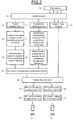
Figure 2 illustrates the steps performed by a steam admission control system of the steam turbine offigure 1 . - As shown on
Figure 1 , a power plant steam turbine 1 comprises a highpressure steam casing 2 and at least on reduced pressure casings. In the illustrated example, the reduced pressure casings correspond to an intermediate steam casing 3 and three lowpressure steam casings - The steam turbine is also provided with
stop valves 7 andcontrol valves 8 upstream of thehigh pressure casing 2, andstop valves 9 andcontrol valves 10 upstream of the intermediate pressure casing 3. - Two moisture-
separator reheaters pressure stop valves 9 andcontrol valves 10. - The steam, supplied by a boiler (not shown here), enters the high
pressure steam casing 2. The admission in the high pressure casing is done through highpressure stop valves 7 and highpressure control valves 8. - After steam expansion in the
high pressure casing 2, the steam is sent to moisture-separator reheaters - The steam is thus admitted in the intermediate pressure casing 3, through the intermediate
pressure stop valves 9 and the intermediatepressure control valves 10, and then admitted in thelow pressure casings - Furthermore, the steam turbine 1 comprises a steam
admission control system 13 which, when the turbine is running and advantageously when a transient occurs, is activated. - As illustrated in
figure 2 , in a first step, thecontrol system 13 determines one or both of theturbine speed 14 and theturbine acceleration 15. - In a second step, the
control system 13 compares the determined speed with a predefinedspeed threshold value 16 and compares the determined acceleration with a predefinedacceleration threshold value 17. - When the determined speed is superior to the predefined
speed threshold value 18 and/or the determined acceleration is superior to the predefinedacceleration threshold value 19, thecontrol system 13 activates a speed andacceleration limiter 20. - In order to regulate the steam admission into the turbine 1 and drop the speed and/or acceleration below the threshold values, the activated speed and
acceleration limiter 20 imposes advantageously controlvalves opening setpoints pressure control valves 8 and to the reduced pressure control valves which are, in that example, the intermediatepressure control valves 10. The controlvalves opening setpoints steam flow demand 23. - In this regard, the
control system 13 may determine asteam flow demand 23 in function ofvarious turbine parameters 24 and the determined speed and/or acceleration values. Theparameters 24 may include, for example, the rotating speed of the turbine, the load, the live steam pressure, the turbine operating mode, limitations and runbacks, and allows the determination of a speed and/or load demand. - In the illustrated embodiment, the steam
admission control system 13 comprises one position-loop card per control valve. The position-loop cards 26 for the highpressure control valves 8 and the position-loop cards 27 for the intermediatepressure control valves 10 are respectively configured to perform the steps of imposing theopening setpoint 21 to the highpressure control valves 8 and imposing theopening setpoint 22 to the intermediatepressure control valves 10. - Moreover, the opening and closing of the
control valves valves control valves - In normal operation, the speed and
acceleration limiter 20 is preferably deactivated, and thecontrol valves steam flow demand 23, itself determined by theparameters 24. - In contrast, during a transient such as a load variation, a grid fault or a switch to house load operating mode, leading to a torque unbalance between the electrical load and the thermal power, the turbine 1 generally accelerates and its speed increases. The speed and
acceleration limiter 20 is only activated if the speed and/or acceleration values exceed the predefined speed and acceleration threshold values. As a response, the speed andacceleration limiter 20 limits the speed and acceleration advantageously by imposing controlvalves opening setpoints pressure control valves 8 and the intermediatepressure control valves 10. - The speed and
acceleration limiter 20 may be configured to derivate the speed continuously in order to calculate the corresponding acceleration and compares the obtained value with the predefined threshold value. Typically, the acceleration predefined threshold value is around 50% of the turbine maximum acceleration. Thus, the speed andacceleration limiter 20 decreases thesteam flow demand 23 according to the deviation between the determined acceleration and the acceleration threshold value. - Furthermore, the speed and
acceleration limiter 20 compares the turbine speed with the speed threshold value. Typically, the speed threshold value is 107% of the turbine nominal speed. Thus, the speed andacceleration limiter 20 decreases thesteam flow demand 23 according to the deviation between the determined speed and the speed threshold value. - Once the situation is normalized, the speed and acceleration values dropped below the speed and acceleration threshold. Thus the speed and
acceleration limiter 20 may be deactivated and thus no longer control the highpressure control valves 8 and the intermediatepressure control valves 10. - Hence, the present invention provides a method allowing regulation of the steam supplied to the high pressure, intermediate pressure and
low pressure casings - The method allows ensuring the safety of the shaft line of the turbine 1 by controlling the shaft-line speed, the load of the turbogenerator and the live steam pressure by a fast and appropriate response.
- The speed and
acceleration limiter 20 realizes a realistic analysis by checking the speed variations, that is to say the result of the unbalance between the power and the load. This improves the availability of the turbine 1 by making the corrective actions on the result rather than a prediction.
Claims (12)
- Method for controlling steam admission into a steam turbine (1), the turbine (1) comprising a high pressure casing (2), at least one reduced pressure casing (3, 4, 5, 6) and an admission steam control system (13), the high pressure casing (2) and at least one reduced pressure casing (3) comprising control valves (8, 10) for steam admission, characterized in that the steam admission control system (13) manages the following steps:determining at least one of the speed (14) and the acceleration (15) of the turbine (1);comparing the determined speed and/or acceleration respectively with a predefined speed threshold value (16) and a predefined acceleration threshold value (17);when the determined speed and/or acceleration are superior to the predefined threshold value (18, 19), the control system (13) activates a speed and acceleration limiter (20).
- Method according to claim 1, wherein the activated speed and acceleration limiter (20) imposes control valve opening setpoints (21, 22), depending on the determined speed and/or acceleration values, to the high pressure and reduced pressure control valves (8, 10) in order to regulate the steam admission into the turbine (1).
- Method according to claim 2, wherein the control valve opening setpoints (21, 22) depend on the turbine (1) steam flow demand (23).
- Method according to claim 3, wherein, the steam flow demand (23) is determined using parameters (24) including at least one of the rotating speed of the turbine (1), the load, the live steam pressure and the turbine (1) operating mode.
- Method according to claim 2, wherein the step of imposing control valve opening setpoints (21, 22) to the control valves (8, 10) is performed through control valve position-loop cards (26, 27).
- Method according to any preceding claim, wherein the speed threshold value is chosen according to the turbine (1) nominal speed.
- Method according to any preceding claim, wherein the acceleration threshold value is chosen according to the turbine (1) maximum acceleration.
- Method according to any preceding claim, wherein the speed and acceleration limiter (20) is deactivated when the turbine (1) speed and acceleration drop below the threshold value.
- Method according to any preceding claim, wherein the control system (13) is activated during a transient of the turbine (1).
- Steam turbine comprising a high pressure casing (2), at least one reduced pressure casing (3, 4, 5, 6) and a steam admission control system (13), the high pressure casing (2) and at least one reduced pressure casing (3) comprising control valves (8, 10) for steam admission, characterized in that the steam admission control system (13) is configured to determine at least one of the speed (14) and the acceleration (15) of the turbine (1), compare the determined speed and/or acceleration respectively with a predefined speed threshold value (16) and a predefined acceleration threshold value (17), and activate a speed and acceleration limiter (20) when the determined speed and/or acceleration are superior to the threshold value (18, 19).
- Steam turbine according to claim 10, wherein hydraulic actuators are provided to perform the opening and closing of the control valves (8, 10), the hydraulic actuators comprising an electro-hydraulic amplifier.
- Steam turbine according to claim 10 or 11, wherein hydraulic actuators are provided to perform the opening and the closing of the control valves (8, 10), the hydraulic actuators comprising a hydraulic fast closing device for emergency closing of the associated control valves.
Priority Applications (5)
| Application Number | Priority Date | Filing Date | Title |
|---|---|---|---|
| EP16290133.4A EP3266987A1 (en) | 2016-07-08 | 2016-07-08 | Turbine speed and acceleration limiter |
| US16/315,798 US20190301307A1 (en) | 2016-07-08 | 2017-07-05 | Turbine speed and acceleration limiter |
| CN201780042546.5A CN109415949A (en) | 2016-07-08 | 2017-07-05 | Turbine trip speed and acceleration restrictor |
| JP2018567616A JP2019525050A (en) | 2016-07-08 | 2017-07-05 | Turbine speed acceleration limiter |
| PCT/EP2017/066817 WO2018007464A1 (en) | 2016-07-08 | 2017-07-05 | Turbine speed and acceleration limiter |
Applications Claiming Priority (1)
| Application Number | Priority Date | Filing Date | Title |
|---|---|---|---|
| EP16290133.4A EP3266987A1 (en) | 2016-07-08 | 2016-07-08 | Turbine speed and acceleration limiter |
Publications (1)
| Publication Number | Publication Date |
|---|---|
| EP3266987A1 true EP3266987A1 (en) | 2018-01-10 |
Family
ID=56609822
Family Applications (1)
| Application Number | Title | Priority Date | Filing Date |
|---|---|---|---|
| EP16290133.4A Withdrawn EP3266987A1 (en) | 2016-07-08 | 2016-07-08 | Turbine speed and acceleration limiter |
Country Status (5)
| Country | Link |
|---|---|
| US (1) | US20190301307A1 (en) |
| EP (1) | EP3266987A1 (en) |
| JP (1) | JP2019525050A (en) |
| CN (1) | CN109415949A (en) |
| WO (1) | WO2018007464A1 (en) |
Families Citing this family (2)
| Publication number | Priority date | Publication date | Assignee | Title |
|---|---|---|---|---|
| FR3049652B1 (en) * | 2016-03-31 | 2020-03-06 | Safran Aircraft Engines | AIRCRAFT TURBOMACHINE WITH DISCHARGE DEVICE |
| US11428115B2 (en) * | 2020-09-25 | 2022-08-30 | General Electric Company | Control of rotor stress within turbomachine during startup operation |
Citations (5)
| Publication number | Priority date | Publication date | Assignee | Title |
|---|---|---|---|---|
| GB2014249A (en) * | 1978-02-09 | 1979-08-22 | Westinghouse Electric Corp | Steam turbine overspeed protection controller |
| US4412780A (en) * | 1981-03-27 | 1983-11-01 | General Electric Company | Rate initial pressure limiter |
| EP2378083A2 (en) * | 2010-04-13 | 2011-10-19 | General Electric Company | Double flow low-pressure steam turbine |
| EP2848774A1 (en) * | 2013-09-17 | 2015-03-18 | Siemens Aktiengesellschaft | Method for testing an overspeed protection system of a single-shaft system |
| GB2524582A (en) * | 2014-03-28 | 2015-09-30 | Mitsubishi Hitachi Power Sys | Combined cycle gas turbine plant |
Family Cites Families (11)
| Publication number | Priority date | Publication date | Assignee | Title |
|---|---|---|---|---|
| JPS5167804A (en) * | 1974-12-11 | 1976-06-11 | Hitachi Ltd | JOKITAABINNOKASOKUBOSHIHOHO OYOBI SONOSOCHI |
| JPS54155303A (en) * | 1978-05-29 | 1979-12-07 | Toshiba Corp | Overspeed preventer for turbine |
| JP3166972B2 (en) * | 1989-02-22 | 2001-05-14 | 株式会社日立製作所 | Power plant control method and apparatus, and power plant |
| JP2854665B2 (en) * | 1990-04-05 | 1999-02-03 | 株式会社東芝 | Steam turbine controller |
| JPH10222203A (en) * | 1997-02-10 | 1998-08-21 | Mitsubishi Heavy Ind Ltd | Digital controller |
| US20080098881A1 (en) * | 2006-10-30 | 2008-05-01 | General Electric Company | Closed loop manual control system and method for an electrically operated hydraulic amplifier |
| CN100474201C (en) * | 2007-01-30 | 2009-04-01 | 北京和利时系统工程有限公司 | Method and device for restricting overspeed of a speed adjustment system |
| KR20130024537A (en) * | 2011-08-31 | 2013-03-08 | 한국전력공사 | Device and method for controlling overspeed of turbine |
| JP2013148040A (en) * | 2012-01-20 | 2013-08-01 | Toshiba Corp | Apparatus and method for controlling steam turbine |
| CN103806959B (en) * | 2012-11-14 | 2015-06-24 | 中国广东核电集团有限公司 | Method and device for preventing disturbances to a steam turbine control system in a nuclear power plant |
| CN103590858B (en) * | 2013-11-19 | 2015-12-02 | 中国神华能源股份有限公司 | Prevent the system and method that Power Plant turbine speed is ascended to heaven |
-
2016
- 2016-07-08 EP EP16290133.4A patent/EP3266987A1/en not_active Withdrawn
-
2017
- 2017-07-05 CN CN201780042546.5A patent/CN109415949A/en active Pending
- 2017-07-05 US US16/315,798 patent/US20190301307A1/en not_active Abandoned
- 2017-07-05 JP JP2018567616A patent/JP2019525050A/en active Pending
- 2017-07-05 WO PCT/EP2017/066817 patent/WO2018007464A1/en not_active Ceased
Patent Citations (5)
| Publication number | Priority date | Publication date | Assignee | Title |
|---|---|---|---|---|
| GB2014249A (en) * | 1978-02-09 | 1979-08-22 | Westinghouse Electric Corp | Steam turbine overspeed protection controller |
| US4412780A (en) * | 1981-03-27 | 1983-11-01 | General Electric Company | Rate initial pressure limiter |
| EP2378083A2 (en) * | 2010-04-13 | 2011-10-19 | General Electric Company | Double flow low-pressure steam turbine |
| EP2848774A1 (en) * | 2013-09-17 | 2015-03-18 | Siemens Aktiengesellschaft | Method for testing an overspeed protection system of a single-shaft system |
| GB2524582A (en) * | 2014-03-28 | 2015-09-30 | Mitsubishi Hitachi Power Sys | Combined cycle gas turbine plant |
Also Published As
| Publication number | Publication date |
|---|---|
| CN109415949A (en) | 2019-03-01 |
| US20190301307A1 (en) | 2019-10-03 |
| WO2018007464A1 (en) | 2018-01-11 |
| JP2019525050A (en) | 2019-09-05 |
Similar Documents
| Publication | Publication Date | Title |
|---|---|---|
| CN101989745B (en) | Method for early detection and anticipatory control of consumer-end load shedding in an electrical grid, and apparatus for carrying out the method | |
| EP2784271B1 (en) | Steam turbine governing system for maintaining synchronization and process for performing the same | |
| US9963995B2 (en) | Method of operating a turbine engine after flame off | |
| RU2016139109A (en) | METHOD FOR DETECTING THE MALFUNCTION OF THE FIRST GAS TURBINE ENGINE OF THE TWO-MOTOR HELICOPTER AND CONTROL OF THE SECOND GAS TURBINE ENGINE AND THE RELATED DEVICE | |
| CN102121403A (en) | Method for operating steam turbine with transient elevated back pressure | |
| JP6396599B2 (en) | Turbine control unit with thermal stress control device as main control device | |
| US20190301307A1 (en) | Turbine speed and acceleration limiter | |
| CA2588879C (en) | Steam turbine plant | |
| JP6482926B2 (en) | Wind generator or wind farm | |
| US12203395B2 (en) | Turbine control valves dynamic interaction | |
| CN103806959B (en) | Method and device for preventing disturbances to a steam turbine control system in a nuclear power plant | |
| CN105508137A (en) | Control system for preventing draught fan from running away | |
| KR102196876B1 (en) | Steam turbine overspeed prevention apparatus | |
| US20200040866A1 (en) | Improvements to Hydraulic Machines During Grid Disconnections | |
| US9976440B2 (en) | Method for testing an overspeed protection mechanism of a single-shaft combined-cycle plant | |
| Bennauer et al. | Optimized steam turbine governor controlling single or multiple grid faults | |
| CN119554101A (en) | A method for preventing turbine from running away during startup | |
| Refan et al. | Role of acceleration control in heavy duty gas turbines during load rejection |
Legal Events
| Date | Code | Title | Description |
|---|---|---|---|
| PUAI | Public reference made under article 153(3) epc to a published international application that has entered the european phase |
Free format text: ORIGINAL CODE: 0009012 |
|
| STAA | Information on the status of an ep patent application or granted ep patent |
Free format text: STATUS: THE APPLICATION HAS BEEN PUBLISHED |
|
| AK | Designated contracting states |
Kind code of ref document: A1 Designated state(s): AL AT BE BG CH CY CZ DE DK EE ES FI FR GB GR HR HU IE IS IT LI LT LU LV MC MK MT NL NO PL PT RO RS SE SI SK SM TR |
|
| AX | Request for extension of the european patent |
Extension state: BA ME |
|
| STAA | Information on the status of an ep patent application or granted ep patent |
Free format text: STATUS: REQUEST FOR EXAMINATION WAS MADE |
|
| 17P | Request for examination filed |
Effective date: 20180730 |
|
| RBV | Designated contracting states (corrected) |
Designated state(s): AL AT BE BG CH CY CZ DE DK EE ES FI FR GB GR HR HU IE IS IT LI LT LU LV MC MK MT NL NO PL PT RO RS SE SI SK SM TR |
|
| STAA | Information on the status of an ep patent application or granted ep patent |
Free format text: STATUS: EXAMINATION IS IN PROGRESS |
|
| 17Q | First examination report despatched |
Effective date: 20190802 |
|
| RIC1 | Information provided on ipc code assigned before grant |
Ipc: F02C 9/28 20060101ALI20200706BHEP Ipc: F01D 17/08 20060101ALI20200706BHEP Ipc: F01D 21/12 20060101ALI20200706BHEP Ipc: F01D 21/02 20060101AFI20200706BHEP |
|
| STAA | Information on the status of an ep patent application or granted ep patent |
Free format text: STATUS: THE APPLICATION IS DEEMED TO BE WITHDRAWN |
|
| 18D | Application deemed to be withdrawn |
Effective date: 20210730 |