EP3266715A1 - Self-forming fuel tank sealant system - Google Patents
Self-forming fuel tank sealant system Download PDFInfo
- Publication number
- EP3266715A1 EP3266715A1 EP17176782.5A EP17176782A EP3266715A1 EP 3266715 A1 EP3266715 A1 EP 3266715A1 EP 17176782 A EP17176782 A EP 17176782A EP 3266715 A1 EP3266715 A1 EP 3266715A1
- Authority
- EP
- European Patent Office
- Prior art keywords
- surface area
- finish
- sealant
- surface energy
- sealed
- Prior art date
- Legal status (The legal status is an assumption and is not a legal conclusion. Google has not performed a legal analysis and makes no representation as to the accuracy of the status listed.)
- Withdrawn
Links
Images

Classifications
-
- F—MECHANICAL ENGINEERING; LIGHTING; HEATING; WEAPONS; BLASTING
- F16—ENGINEERING ELEMENTS AND UNITS; GENERAL MEASURES FOR PRODUCING AND MAINTAINING EFFECTIVE FUNCTIONING OF MACHINES OR INSTALLATIONS; THERMAL INSULATION IN GENERAL
- F16J—PISTONS; CYLINDERS; SEALINGS
- F16J15/00—Sealings
- F16J15/02—Sealings between relatively-stationary surfaces
- F16J15/04—Sealings between relatively-stationary surfaces without packing between the surfaces, e.g. with ground surfaces, with cutting edge
-
- B—PERFORMING OPERATIONS; TRANSPORTING
- B64—AIRCRAFT; AVIATION; COSMONAUTICS
- B64D—EQUIPMENT FOR FITTING IN OR TO AIRCRAFT; FLIGHT SUITS; PARACHUTES; ARRANGEMENT OR MOUNTING OF POWER PLANTS OR PROPULSION TRANSMISSIONS IN AIRCRAFT
- B64D37/00—Arrangements in connection with fuel supply for power plant
- B64D37/02—Tanks
- B64D37/06—Constructional adaptations thereof
-
- B—PERFORMING OPERATIONS; TRANSPORTING
- B64—AIRCRAFT; AVIATION; COSMONAUTICS
- B64F—GROUND OR AIRCRAFT-CARRIER-DECK INSTALLATIONS SPECIALLY ADAPTED FOR USE IN CONNECTION WITH AIRCRAFT; DESIGNING, MANUFACTURING, ASSEMBLING, CLEANING, MAINTAINING OR REPAIRING AIRCRAFT, NOT OTHERWISE PROVIDED FOR; HANDLING, TRANSPORTING, TESTING OR INSPECTING AIRCRAFT COMPONENTS, NOT OTHERWISE PROVIDED FOR
- B64F5/00—Designing, manufacturing, assembling, cleaning, maintaining or repairing aircraft, not otherwise provided for; Handling, transporting, testing or inspecting aircraft components, not otherwise provided for
- B64F5/40—Maintaining or repairing aircraft
- B64F5/45—Repairing leakages in fuel tanks
Definitions
- This disclosure pertains to a self-forming sealant system.
- this disclosure pertains to a self-forming seal between two parts or between a fastener and a part.
- a first finish having a high surface energy is applied to the joint between the two parts or is applied to the fastener and the part.
- a second finish having a low surface energy is then applied adjacent to the area where the first finish was applied.
- a sealant is then applied between the joint between the two parts or the fastener and the part, where the sealant migrates to the joint or fastener coated with the first finish having the high surface energy and away from the areas adjacent the joint or the fastener coated by the second finish having the low surface energy.
- a technician applies the sealant by hand.
- the sealant is typically in a low/sag thixotropic paste form.
- the technician will apply the sealant around hundreds and potentially thousands of fasteners in the fuel tank structure by a paint brush. Additionally, applying sealant to fasteners in the structure often requires the technician to manipulate the brush in some very confined spaces.
- the sealant is applied by a sealant gun similar to a caulk gun that is used to apply caulk in residential applications. The technician applies the sealant using the sealant gun and then forms the applied sealant to the joints by hand using a tool that resembles a spatula.
- the technician applying sealant around the structure fasteners using a paint brush and applying sealant along the joints of the structure using the spatula are both time consuming processes.
- the technicians who apply sealant in aircraft applications, for example an aircraft fuel tank are typically required to work 12 hour days, seven days a week. Given the manual and repetitive nature of applying the sealant, the application of the sealant can lead to repetitive stress injuries to the technician.
- Inspection of the sealant applied to the structure requires an inspector to come to the work site and inspect every sealed fastener and every inch of sealed joint on the structure. This inspection process is also time consuming, both in waiting for the inspector to be available at the work site, and for the inspector to inspect every sealed fastener and every inch of sealed joint. While the inspection is conducted, the technician waits for the inspection to be complete. Furthermore, the inspection process is prone to human error and human subjectivity.
- the self-forming fuel tank sealant system of this disclosure uses wetting physics to produce the final fillet shape of sealant applied to a joint between two parts and/or a fastener and a part, instead of the technician's spatula or paintbrush.
- the shape of sealant when applied to the joint or fastener is unimportant.
- the sealed structure for example the sealed aircraft fuel tank may be produced by first coating a first surface area on the structure where the seal is desired with a first finish having a high surface energy. A second surface area on the structure where the seal is not needed is then coated with a second finish having a low surface energy. The surface energy of the second finish is considerably lower than the surface energy of the first finish.
- a sealant is then applied to the structure where the seal is desired.
- the sealant is applied on the first surface area of the structure that has been coated with the first finish having the high surface energy.
- the physics of wetting will result in the sealant spreading out over the first surface area coated by the first finish having the high surface energy, and beading up on and flowing off of the second surface area on the structure coated with the second finish having the low surface energy.
- the sealed structure for example the sealed aircraft fuel tank may be produced by first coating a first surface area on the structure where the seal is desired with a first finish having a first surface energy. A second surface area on the structure where the seal is not needed is then coated with a second finish having a second surface energy, wherein the surface energy of the second finish is lower than the surface energy of the first finish, preferably, considerably lower.
- a sealant is then applied to the structure where the seal is desired.
- the sealant is applied on the first surface area of the structure that has been coated with the first finish having the higher surface energy.
- the physics of wetting will result in the sealant spreading out over the first surface area coated by the first finish having the higher surface energy, and beading up on and flowing off of the second surface area on the structure coated with the second finish having the lower surface energy.
- Producing the sealed structure by the self-forming sealant system can be achieved by a spray process that efficiently applies the sealant to the areas of the structure coated with the high surface energy finish where the seal is desired.
- the sealant sprayed on the areas of the structure coated with the low surface energy finish where sealant is not desired will bead up and flow off of these areas. This spraying process would allow faster sealant application to joints of the structure and fasteners of the structure.
- the sealant meniscus will terminate on the high energy surface and the shape the sealant forms will have a contact angle of zero degrees with respect to the surface. If there is sufficient sealant, the meniscus will extend all the way to the interface between the high surface energy finish and the low surface energy finish, and will terminate at that interface with some non-zero contact angle. Thus, there is a simple test to ensure that the sealant volume applied to the joint or fastener is sufficient and the seal is correct. If there is a corner between the sealant and the surface, then there is sufficient volume of sealant and thus sufficient extent of the seal.
- Surfaces with a high surface energy may have a surface energy of 38 mJ/m 2 or higher, and surfaces with a low surface energy may have a surface energy of less than 38 mJ/m 2 .
- the surface energy of a surface may be measured using a tensiometer.
- the surface energy may be measured using the Dyne QuickTest Pen produced by Dyne Testing Ltd. This QuickTest pen can be used to identify if the surface has a surface energy of 38 mJ/m 2 or higher. In order to do this, a user draws the Dyne QuickTest Pen tip across the surface to be tested. If the ink line shrinks or beads within 1 to 2 seconds then the surface does not have a surface energy of 38 mJ/m 2 . However, if the Dyne QuickTest Pen line remains as marked and does not shrink then the surface has a surface energy of a surface energy of 38 mJ/m 2 or higher.
- exemplary method 10 may include specification and design 14 of the aircraft 12 and material procurement 16.
- component and subassembly manufacturing 18 and system integration 20 of the aircraft 12 takes place.
- the aircraft 12 may go through certification and delivery 22 in order to be placed in service 24.
- routine maintenance and service 26 which may also include modification, reconfiguration, refurbishment, and so on).
- a system integrator may include without limitation any number of aircraft manufacturers and major-system subcontractors; a third party may include without limitation any number of venders, subcontractors, and suppliers; and an operator may be an airline, leasing company, military entity, service organization, and so on.
- the aircraft 12 produced by exemplary method 10 may include an airframe 28 with a plurality of systems 30 and an interior 32.
- high-level systems 30 include one or more of a propulsion system 34, an electrical system 36, a hydraulic system 38, and an environmental system 40. Any number of other systems may be included.
- an aerospace example is shown (aircraft, rockets), the principles of the invention may be applied to other industries, such as the automotive, railroad or tooling industry.
- Apparatus and methods embodied herein may be employed during any one or more of the stages of the production and service method 10.
- components or subassemblies corresponding to production process 18 may be fabricated or manufactured in a manner similar to components or subassemblies produced while the aircraft 12 is in service.
- one or more apparatus embodiments, method embodiments, or a combination thereof may be utilized during the production stages 18 and 20, for example, by substantially expediting assembly of or reducing the cost of an aircraft 12.
- apparatus embodiments, method embodiments, or a combination thereof may be utilized while the aircraft 12 is in service, for example and without limitation, to maintenance and service 26.
- Figures 3 and 4 show representations of the self-forming sealant system that seals a joint line 42 between two parts or panels 44, 46.
- the two parts 44, 46 could be parts of a liquid containing tank, for example an aircraft fuel tank, or parts of another structure in which parts of the structure connected along a joint line are required to be sealed along the joint line.
- the parts or panels 44, 46 could be metallic material parts such as aluminum parts, composite material parts or other equivalent types of materials.
- the joint line 42 comprises the edge of one part 44 and may include a portion of the contacting surfaces of the parts 44, 46.
- the overlapping portions of the parts 44, 46 could be held together by welds, adhesives, fasteners or by other equivalent means.
- a first surface area 50 on the structure is represented between the dashed lines 52, 54 in Figure 3 and the dashed lines 56, 58 in Figure 4 .
- the first surface area 50 is the area of the structure 48 where the seal is desired.
- This first surface area has a high surface energy.
- the high surface energy could be a characteristic of the materials of the two parts 44, 46 in the first surface area 50.
- the high surface energy could be the result of coating the first surface area 50 between the dashed lines 52, 54 in Figure 3 and the dashed lines 56, 58 in Figure 4 with a first finish, where the first finish has a high surface energy. Coating the first surface area 50 with the first finish also coats the joint line 42 in the first surface area with the first finish.
- the structure 48 also has a second surface area 60 that is juxtaposed to the first surface area 50 but separate from the first surface area 50.
- the second surface area 60 on the structure 48 is to the left of the dashed line 52 shown in Figure 3 and to the left of the dashed line 56 shown in Figure 4 .
- the structure 48 has a third surface area 62 that is juxtaposed to the first surface area 50 but is separate from the first surface area 50.
- the third surface area 62 is just to the right of the dashed line 54 shown in Figure 3 and to the right of the dashed line 58 shown in Figure 4 .
- the second surface area 60 and the third surface area 62 are on opposite sides of the first surface area 50 and have a low surface energy.
- the low surface energy of the second surface area 60 and the third surface area 62 could be a characteristic of the materials of the two parts 44, 46 joined on the structure 48.
- the second surface area 60 and the third surface area 62 could be coated with a second finish where the second finish has a low surface energy.
- the low surface energy of the second surface area and third surface area is considerably lower than the high surface energy of the first surface area. In the example of Figures 3 and 4 , the seal is not needed on the second surface area 60 and the third surface area 62.
- the sealant 66 is applied to the structure 48 on and along the joint line 42.
- the sealant 66 is applied on the first finish coating the first surface area 50 on the structure 48 having the high surface energy where the seal is desired.
- the physics of wetting will result in the sealant 66 spreading out over the first surface area 50 on the structure 48 having the high surface energy, and beading up on and flowing off of the second surface area 60 and the third surface area 62 on the structure 48 having the low surface energy.
- Figures 5 and 6 show representations of a further application of the self-forming sealant system of this disclosure that seals a joint line 72 between two parts or panels 74, 76 of a structure 78.
- the two parts 74, 76 could be parts of a liquid containing tank, for example an aircraft fuel tank, or parts of another structure in which the parts of the structure connected along the joint line 72 are required to be sealed along the joint line.
- the parts or panels 74, 76 could be metal parts such as aluminum parts, composite parts or other equivalent types of materials.
- the joint line 72 is formed between two abutting edges of the parts 74, 76.
- the abutting edges of the parts 74, 76 could be held together by welds, by adhesives, by fasteners or by other equivalent means.
- a first surface area 80 on the structure 78 is represented between the dashed lines 82, 84 in Figure 5 and between the dashed lines 86, 88 in Figure 6 .
- This first surface area 80 is the area of the structure 78 where the seal is desired.
- the first surface area 80 has a high surface energy.
- the high surface energy could be a characteristic of the materials of the two parts 74, 76 in the first surface area 80.
- the high surface energy could be the result of a first finish coating the first surface area 80 between the dashed lines 82, 84 in Figure 3 and the dashed lines 86, 88 in Figure 4 , where the first finish has a high surface energy.
- the structure 78 also has a second surface area 90 that is juxtaposed to the first surface area 80 but separate from the first surface area 80.
- the second surface area 90 on the structure 78 is to the left of the dashed line 82 shown in Figure 5 and to the left of the dashed line 86 shown in Figure 6 .
- the structure 78 has a third surface area 92 that is juxtaposed to the first surface area 80 but is separate from the first surface area 80.
- the third surface area 92 is just to the right of the dashed line 84 shown in Figure 5 and to the right of the dashed line 88 shown in Figure 6 .
- the second surface area 90 and the third surface area 92 have a low surface energy.
- the low surface energy of the second surface area 90 and the third surface area 92 could be a characteristic of the materials of the two parts 74, 76 joined on the structure 78.
- the second surface area 90 and the third surface area 92 could be coated with a second finish where the second finish has a low surface energy.
- the low surface energy of the second surface area and third surface area is considerably lower than the high surface energy of the first surface area. In the example of Figures 5 and 6 , the seal is not needed on the second surface area 90 and the third surface area 92.
- the sealant 96 is applied to the structure 78 along the joint line 72.
- the sealant 96 is applied on the first surface area 80 on the structure 78 having the high surface energy where the seal is desired.
- the physics of wetting will result in the sealant 96 spreading out over the first surface area 80 on the structure 78 having the high surface energy, and beading up on and flowing off of the second surface area 90 and the third surface area 92 on the structure 78 having a low surface energy.
- Figures 7 and 8 show representations of the self-forming sealant system that seals fasteners 98, 100 that attach two parts 102, 104 of a structure 106 together.
- the two parts 102, 104 could be parts of a liquid containing tank, for example an aircraft fuel tank, or parts of another structure in which parts of the structure connected by fasteners are required to be sealed at the fastener connections.
- the parts 102, 104 could be metal parts such as aluminum parts, composite parts or equivalent types of materials.
- the fasteners 98, 100 are typically metal parts.
- first surface areas 110 on the structure are represented by the dashed lines 112 in Figure 7 and the dashed lines 114, 116 in Figure 8 .
- the first surface areas 110 are the areas of the structure 106 where the seals are desired.
- the first surface areas 110 have a high surface energy.
- the fasteners 98, 100 also have a high surface energy.
- the high surface energy could be a characteristic of the materials of the part 102 in the first surface areas 110 and a characteristic of the materials of the fasteners 98, 100.
- the high surface energy could be a result of a first finish coating the first surface areas 110 and the fasteners 98, 100 within the dashed lines 112 of Figure 7 and within the dashed lines 114, 116 of Figure 8 , where the first finish has a high surface energy. Coating the first surface areas 110 with the first finish also coats the fasteners 98, 100 with the first finish.
- the structure 106 also has a second surface area 118 that is juxtaposed to the first surface areas 110 but is separate from the first surface areas 110 and outside of the first surface areas 110.
- the second surface area 118 on the structure 106 is outside of and surrounds the dashed lines 112 shown in Figure 7 .
- the second surface area 118 has a low surface energy.
- the low surface energy of the second surface area 118 could be a characteristic of the materials of the part 102 outside of the dashed lines 112.
- the second surface area 118 could be coated with a second finish where the second finish has a low surface energy.
- the low surface energy of the second finish is considerably lower than the high surface energy of the first finish.
- the seal is not needed on the second surface area 118.
- the sealant 120 is applied to the first part 102 of the structure 106 and on the fasteners 98, 100.
- the sealant 120 is applied on the first surface areas 110 on the structure 106 having the high surface energy where the seal is desired.
- the physics of wetting will result in the sealant 120 spreading out over the first surface areas 110 on the structure 106 having the high surface energy, and beading up and flowing off of the second surface area 118 having the low surface energy.
- the first surface may be an aluminium surface
- the second surface may be coated with a Teflon® (PTFE, polytetrafluoroethylene) film.
- PTFE polytetrafluoroethylene
- the surface energy of the aluminum surface (the first surface) is higher than the surface energy of the Teflon coated surface (the second surface).
- the first surface may be an epoxy surface
- the second surface may be coated with Teflon.
- the surface energy of the epoxy surface (the first surface) is higher than the surface energy of the Teflon coated surface (the second surface).
- the sealant may be Pro-Seal 890 supplied by PPG Aerospace.
- the sealant can be applied by a spray process that efficiently applies a sealant to the areas of the structure coated with the high surface energy finish where the seal is desired.
- the sealant sprayed on the areas of the structure coated with the low surface energy finish where the sealant is not desired will bead up and flow off of these areas. This spraying process will allow faster sealant application to joints of the structure and fasteners of the structure.
- the sealant meniscus will terminate on the high energy surface and the shape the sealant forms will have a contact angle of zero degrees with respect to the surface. If there is sufficient sealant, the meniscus will extend all the way to the interface between the high surface energy finish and the low surface energy finish, and will terminate at that interface with some non-zero contact angle. Thus, there is a simple test to ensure that the sealant volume applied to the joint or fastener is sufficient and the seal is correct. If there is a corner between the sealant and the surface, then there is sufficient volume of sealant and thus sufficient extent of the seal.
Landscapes
- Engineering & Computer Science (AREA)
- Aviation & Aerospace Engineering (AREA)
- General Engineering & Computer Science (AREA)
- Manufacturing & Machinery (AREA)
- Transportation (AREA)
- Mechanical Engineering (AREA)
- Application Of Or Painting With Fluid Materials (AREA)
Abstract
Description
- This disclosure pertains to a self-forming sealant system. In particular, this disclosure pertains to a self-forming seal between two parts or between a fastener and a part. In forming the seal, a first finish having a high surface energy is applied to the joint between the two parts or is applied to the fastener and the part. A second finish having a low surface energy is then applied adjacent to the area where the first finish was applied. A sealant is then applied between the joint between the two parts or the fastener and the part, where the sealant migrates to the joint or fastener coated with the first finish having the high surface energy and away from the areas adjacent the joint or the fastener coated by the second finish having the low surface energy.
- In current methods of sealing a structure against liquid leaks, for example an aircraft fuel tank, ensuring liquid will not leak from the structure is a very time consuming process. A sealant must be applied over all of the joints of the structure and over all of the fasteners of the structure. This application of sealant can take considerable time.
- Additionally, inspecting the sealant applied to the joints of the structure and the fasteners of the structure is also very time consuming.
- In current methods of sealing joints between two parts of a structure and/or sealing a fastener in a part of a structure, a technician applies the sealant by hand. The sealant is typically in a low/sag thixotropic paste form. In a structure such as an aircraft fuel tank, the technician will apply the sealant around hundreds and potentially thousands of fasteners in the fuel tank structure by a paint brush. Additionally, applying sealant to fasteners in the structure often requires the technician to manipulate the brush in some very confined spaces. Along joints of the structure, the sealant is applied by a sealant gun similar to a caulk gun that is used to apply caulk in residential applications. The technician applies the sealant using the sealant gun and then forms the applied sealant to the joints by hand using a tool that resembles a spatula.
- The technician applying sealant around the structure fasteners using a paint brush and applying sealant along the joints of the structure using the spatula are both time consuming processes. The technicians who apply sealant in aircraft applications, for example an aircraft fuel tank are typically required to work 12 hour days, seven days a week. Given the manual and repetitive nature of applying the sealant, the application of the sealant can lead to repetitive stress injuries to the technician.
- Inspection of the sealant applied to the structure requires an inspector to come to the work site and inspect every sealed fastener and every inch of sealed joint on the structure. This inspection process is also time consuming, both in waiting for the inspector to be available at the work site, and for the inspector to inspect every sealed fastener and every inch of sealed joint. While the inspection is conducted, the technician waits for the inspection to be complete. Furthermore, the inspection process is prone to human error and human subjectivity.
- The self-forming fuel tank sealant system of this disclosure uses wetting physics to produce the final fillet shape of sealant applied to a joint between two parts and/or a fastener and a part, instead of the technician's spatula or paintbrush. In the self-forming sealant system the shape of sealant when applied to the joint or fastener is unimportant.
- The sealed structure, for example the sealed aircraft fuel tank may be produced by first coating a first surface area on the structure where the seal is desired with a first finish having a high surface energy. A second surface area on the structure where the seal is not needed is then coated with a second finish having a low surface energy. The surface energy of the second finish is considerably lower than the surface energy of the first finish.
- A sealant is then applied to the structure where the seal is desired. The sealant is applied on the first surface area of the structure that has been coated with the first finish having the high surface energy. The physics of wetting will result in the sealant spreading out over the first surface area coated by the first finish having the high surface energy, and beading up on and flowing off of the second surface area on the structure coated with the second finish having the low surface energy.
- The sealed structure, for example the sealed aircraft fuel tank may be produced by first coating a first surface area on the structure where the seal is desired with a first finish having a first surface energy. A second surface area on the structure where the seal is not needed is then coated with a second finish having a second surface energy, wherein the surface energy of the second finish is lower than the surface energy of the first finish, preferably, considerably lower.
- A sealant is then applied to the structure where the seal is desired. The sealant is applied on the first surface area of the structure that has been coated with the first finish having the higher surface energy. The physics of wetting will result in the sealant spreading out over the first surface area coated by the first finish having the higher surface energy, and beading up on and flowing off of the second surface area on the structure coated with the second finish having the lower surface energy.
- Producing the sealed structure by the self-forming sealant system can be achieved by a spray process that efficiently applies the sealant to the areas of the structure coated with the high surface energy finish where the seal is desired. The sealant sprayed on the areas of the structure coated with the low surface energy finish where sealant is not desired will bead up and flow off of these areas. This spraying process would allow faster sealant application to joints of the structure and fasteners of the structure.
- If the sealant volume applied to a joint or fastener coated with the high surface energy finish is low, the sealant meniscus will terminate on the high energy surface and the shape the sealant forms will have a contact angle of zero degrees with respect to the surface. If there is sufficient sealant, the meniscus will extend all the way to the interface between the high surface energy finish and the low surface energy finish, and will terminate at that interface with some non-zero contact angle. Thus, there is a simple test to ensure that the sealant volume applied to the joint or fastener is sufficient and the seal is correct. If there is a corner between the sealant and the surface, then there is sufficient volume of sealant and thus sufficient extent of the seal.
- Surfaces with a high surface energy may have a surface energy of 38 mJ/m2 or higher, and surfaces with a low surface energy may have a surface energy of less than 38 mJ/m2. The surface energy of a surface may be measured using a tensiometer. For example, the surface energy may be measured using the Dyne QuickTest Pen produced by Dyne Testing Ltd. This QuickTest pen can be used to identify if the surface has a surface energy of 38 mJ/m2 or higher. In order to do this, a user draws the Dyne QuickTest Pen tip across the surface to be tested. If the ink line shrinks or beads within 1 to 2 seconds then the surface does not have a surface energy of 38 mJ/m2. However, if the Dyne QuickTest Pen line remains as marked and does not shrink then the surface has a surface energy of a surface energy of 38 mJ/m2 or higher.
- The features, functions and advantages that have been discussed can be achieved independently in various embodiments or may be combined in yet other embodiments, further details of which can be seen with reference to the following description and drawings.
-
-
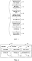
Figure 1 is a flow diagram of aircraft production and service methodology; -
Figure 2 is a block diagram of an aircraft; -
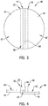
Figure 3 is a representation of a plan view of a sealed joint along two parts or panels of a structure provided by the self-forming fuel tank sealant system of this disclosure. -
Figure 4 is a representation of a side elevation view of the joint inFigure 3 . -
Figure 5 is a representation of a plan view of a sealed joint between two parts or two panels of a structure provided by the self-forming fuel tank sealant system of the disclosure. -
Figure 6 is a representation of a side elevation view of the seal shown inFigure 5 . -
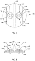
Figure 7 is a representation of a plan view of seals on fasteners in parts or panels of a structure provided by the self-forming fuel tank sealant system of this disclosure. -
Figure 8 is a representation of a side elevation view of the seals shown inFigure 7 . - Referring more particularly to the drawings, embodiments of the disclosure may be described in the context of an aircraft manufacturing and
service method 10 as shown inFigure 1 and anaircraft 12 as shown inFigure 2 . During pre-production,exemplary method 10 may include specification and design 14 of theaircraft 12 andmaterial procurement 16. During production, component andsubassembly manufacturing 18 andsystem integration 20 of theaircraft 12 takes place. Thereafter, theaircraft 12 may go through certification anddelivery 22 in order to be placed inservice 24. While in service by a customer, theaircraft 12 is scheduled for routine maintenance and service 26 (which may also include modification, reconfiguration, refurbishment, and so on). - Each of the processes of
method 10 may be performed or carried out by a system integrator, a third party, and/or an operator (e.g., a customer). For the purposes of this description, a system integrator may include without limitation any number of aircraft manufacturers and major-system subcontractors; a third party may include without limitation any number of venders, subcontractors, and suppliers; and an operator may be an airline, leasing company, military entity, service organization, and so on. - As shown in
Figure 2 , theaircraft 12 produced byexemplary method 10 may include anairframe 28 with a plurality ofsystems 30 and an interior 32. Examples of high-level systems 30 include one or more of apropulsion system 34, anelectrical system 36, ahydraulic system 38, and anenvironmental system 40. Any number of other systems may be included. Although an aerospace example is shown (aircraft, rockets), the principles of the invention may be applied to other industries, such as the automotive, railroad or tooling industry. - Apparatus and methods embodied herein may be employed during any one or more of the stages of the production and
service method 10. For example, components or subassemblies corresponding toproduction process 18 may be fabricated or manufactured in a manner similar to components or subassemblies produced while theaircraft 12 is in service. Also, one or more apparatus embodiments, method embodiments, or a combination thereof may be utilized during the production stages 18 and 20, for example, by substantially expediting assembly of or reducing the cost of anaircraft 12. Similarly, one or more of apparatus embodiments, method embodiments, or a combination thereof may be utilized while theaircraft 12 is in service, for example and without limitation, to maintenance andservice 26. -
Figures 3 and 4 show representations of the self-forming sealant system that seals ajoint line 42 between two parts orpanels parts panels Figures 3 and 4 thejoint line 42 comprises the edge of onepart 44 and may include a portion of the contacting surfaces of theparts parts - On the sealed
structure 48 represented inFigures 3 and 4 , afirst surface area 50 on the structure is represented between the dashedlines Figure 3 and the dashedlines Figure 4 . Thefirst surface area 50 is the area of thestructure 48 where the seal is desired. This first surface area has a high surface energy. The high surface energy could be a characteristic of the materials of the twoparts first surface area 50. Alternatively, the high surface energy could be the result of coating thefirst surface area 50 between the dashedlines Figure 3 and the dashedlines Figure 4 with a first finish, where the first finish has a high surface energy. Coating thefirst surface area 50 with the first finish also coats thejoint line 42 in the first surface area with the first finish. - The
structure 48 also has asecond surface area 60 that is juxtaposed to thefirst surface area 50 but separate from thefirst surface area 50. In the example, thesecond surface area 60 on thestructure 48 is to the left of the dashedline 52 shown inFigure 3 and to the left of the dashedline 56 shown inFigure 4 . Additionally, thestructure 48 has athird surface area 62 that is juxtaposed to thefirst surface area 50 but is separate from thefirst surface area 50. In the example ofFigures 3 and 4 , thethird surface area 62 is just to the right of the dashedline 54 shown inFigure 3 and to the right of the dashedline 58 shown inFigure 4 . Thesecond surface area 60 and thethird surface area 62 are on opposite sides of thefirst surface area 50 and have a low surface energy. The low surface energy of thesecond surface area 60 and thethird surface area 62 could be a characteristic of the materials of the twoparts structure 48. Alternatively, thesecond surface area 60 and thethird surface area 62 could be coated with a second finish where the second finish has a low surface energy. The low surface energy of the second surface area and third surface area is considerably lower than the high surface energy of the first surface area. In the example ofFigures 3 and 4 , the seal is not needed on thesecond surface area 60 and thethird surface area 62. - The
sealant 66 is applied to thestructure 48 on and along thejoint line 42. Thesealant 66 is applied on the first finish coating thefirst surface area 50 on thestructure 48 having the high surface energy where the seal is desired. The physics of wetting will result in thesealant 66 spreading out over thefirst surface area 50 on thestructure 48 having the high surface energy, and beading up on and flowing off of thesecond surface area 60 and thethird surface area 62 on thestructure 48 having the low surface energy. - Although only a small portion of the
structure 48 and thejoint line 42 on the structure is represented inFigures 3 and 4 , it should be understood that the self-forming sealant system would be applied to all of the joint lines of thestructure 48 that require a seal. -
Figures 5 and 6 show representations of a further application of the self-forming sealant system of this disclosure that seals ajoint line 72 between two parts orpanels structure 78. The twoparts joint line 72 are required to be sealed along the joint line. The parts orpanels Figures 5 and 6 thejoint line 72 is formed between two abutting edges of theparts parts - On the sealed
structure 78 represented inFigures 5 and 6 , afirst surface area 80 on thestructure 78 is represented between the dashedlines Figure 5 and between the dashedlines Figure 6 . Thisfirst surface area 80 is the area of thestructure 78 where the seal is desired. Thefirst surface area 80 has a high surface energy. The high surface energy could be a characteristic of the materials of the twoparts first surface area 80. Alternatively, the high surface energy could be the result of a first finish coating thefirst surface area 80 between the dashedlines Figure 3 and the dashedlines Figure 4 , where the first finish has a high surface energy. - The
structure 78 also has asecond surface area 90 that is juxtaposed to thefirst surface area 80 but separate from thefirst surface area 80. In the example ofFigures 5 and 6 , thesecond surface area 90 on thestructure 78 is to the left of the dashedline 82 shown inFigure 5 and to the left of the dashedline 86 shown inFigure 6 . Additionally, thestructure 78 has athird surface area 92 that is juxtaposed to thefirst surface area 80 but is separate from thefirst surface area 80. In the example ofFigures 5 and 6 , thethird surface area 92 is just to the right of the dashedline 84 shown inFigure 5 and to the right of the dashedline 88 shown inFigure 6 . Thesecond surface area 90 and thethird surface area 92 have a low surface energy. The low surface energy of thesecond surface area 90 and thethird surface area 92 could be a characteristic of the materials of the twoparts structure 78. Alternatively, thesecond surface area 90 and thethird surface area 92 could be coated with a second finish where the second finish has a low surface energy. The low surface energy of the second surface area and third surface area is considerably lower than the high surface energy of the first surface area. In the example ofFigures 5 and 6 , the seal is not needed on thesecond surface area 90 and thethird surface area 92. - The
sealant 96 is applied to thestructure 78 along thejoint line 72. Thesealant 96 is applied on thefirst surface area 80 on thestructure 78 having the high surface energy where the seal is desired. The physics of wetting will result in thesealant 96 spreading out over thefirst surface area 80 on thestructure 78 having the high surface energy, and beading up on and flowing off of thesecond surface area 90 and thethird surface area 92 on thestructure 78 having a low surface energy. - Although only a small portion of the
structure 78 and thejoint line 72 on the structure is represented inFigures 5 and 6 , it should be understood that the self-forming sealant system would be applied to all of the joint lines of thestructure 78 that require a seal. -
Figures 7 and 8 show representations of the self-forming sealant system that sealsfasteners parts structure 106 together. Again, the twoparts parts fasteners - On the sealed
structure 106 represented inFigures 7 and 8 ,first surface areas 110 on the structure are represented by the dashedlines 112 inFigure 7 and the dashedlines Figure 8 . Thefirst surface areas 110 are the areas of thestructure 106 where the seals are desired. Thefirst surface areas 110 have a high surface energy. Thefasteners part 102 in thefirst surface areas 110 and a characteristic of the materials of thefasteners first surface areas 110 and thefasteners lines 112 ofFigure 7 and within the dashedlines Figure 8 , where the first finish has a high surface energy. Coating thefirst surface areas 110 with the first finish also coats thefasteners - The
structure 106 also has asecond surface area 118 that is juxtaposed to thefirst surface areas 110 but is separate from thefirst surface areas 110 and outside of thefirst surface areas 110. In the example ofFigures 7 and 8 , thesecond surface area 118 on thestructure 106 is outside of and surrounds the dashedlines 112 shown inFigure 7 . Thesecond surface area 118 has a low surface energy. The low surface energy of thesecond surface area 118 could be a characteristic of the materials of thepart 102 outside of the dashedlines 112. Alternatively, thesecond surface area 118 could be coated with a second finish where the second finish has a low surface energy. The low surface energy of the second finish is considerably lower than the high surface energy of the first finish. In the example ofFigures 7 and 8 , the seal is not needed on thesecond surface area 118. - The
sealant 120 is applied to thefirst part 102 of thestructure 106 and on thefasteners sealant 120 is applied on thefirst surface areas 110 on thestructure 106 having the high surface energy where the seal is desired. The physics of wetting will result in thesealant 120 spreading out over thefirst surface areas 110 on thestructure 106 having the high surface energy, and beading up and flowing off of thesecond surface area 118 having the low surface energy. - Although only two
fasteners structure 106 are represented inFigures 7 and 8 , it should be understood that the self-forming sealant system would be applied to all of the fasteners of thestructure 106 that require a seal. - In some embodiments of the sealed structure, the first surface may be an aluminium surface, and the second surface may be coated with a Teflon® (PTFE, polytetrafluoroethylene) film. In this embodiment, the surface energy of the aluminum surface (the first surface) is higher than the surface energy of the Teflon coated surface (the second surface).
- In an alternative embodiment of the sealed structure, the first surface may be an epoxy surface, and the second surface may be coated with Teflon. In this embodiment, the surface energy of the epoxy surface (the first surface) is higher than the surface energy of the Teflon coated surface (the second surface).
- In some embodiments of the sealed structure, the sealant may be Pro-Seal 890 supplied by PPG Aerospace. In each of the examples of the self-forming sealant system discussed above, the sealant can be applied by a spray process that efficiently applies a sealant to the areas of the structure coated with the high surface energy finish where the seal is desired. The sealant sprayed on the areas of the structure coated with the low surface energy finish where the sealant is not desired will bead up and flow off of these areas. This spraying process will allow faster sealant application to joints of the structure and fasteners of the structure.
- If the sealant volume applied to a joint or fastener coated with the high surface energy finish is low, the sealant meniscus will terminate on the high energy surface and the shape the sealant forms will have a contact angle of zero degrees with respect to the surface. If there is sufficient sealant, the meniscus will extend all the way to the interface between the high surface energy finish and the low surface energy finish, and will terminate at that interface with some non-zero contact angle. Thus, there is a simple test to ensure that the sealant volume applied to the joint or fastener is sufficient and the seal is correct. If there is a corner between the sealant and the surface, then there is sufficient volume of sealant and thus sufficient extent of the seal.
- Clause 1. A sealed structure comprising: a first surface area on the structure, the first surface area having a high surface energy;
a second surface area on the structure, the second surface area having a low surface energy, the low surface energy being less than the high surface energy; and,
a sealant on the first surface area on the structure, the sealant being substantially absent from the second surface area on the structure. - Clause 2. The sealed structure of Clause 1, further comprising:
- the first surface area on the structure and the second surface area on the structure being juxtaposed.
- Clause 3. The sealed structure of Clauses 1 or 2, further comprising:
- the second surface area on the structure surrounding the first surface area on the structure.
- Clause 4. The sealed structure of Clauses 1-3, further comprising:
- a third surface area on the structure, the third surface area having the low surface energy; and,
- the second surface area on the structure and the third surface area on the structure being on opposite sides of the first surface area on the structure.
- Clause 5. The sealed structure of Clause 4, further comprising:
- the second surface area on the structure and the third surface area on the structure being juxtaposed to the first surface area on the structure.
- Clause 6. The sealed structure of Clauses 1-5, further comprising:
- a first part of the structure;
- a second part of the structure;
- a joint line between the first part of the structure and the second part of the structure; and,
- the joint line being in the first surface area on the structure.
- Clause 7. The sealed structure of Clauses 1-6, further comprising:
- a fastener on the first surface area on the structure;
the sealant being on the fastener. - Clause 8. A sealed structure comprising: a first surface area on the structure, the first surface area having a first surface energy;
a second surface area on the structure, the second surface area having a second surface energy, the second surface energy being less than the first surface energy; and,
a sealant on the first surface area on the structure, the sealant being substantially absent from the second surface area on the structure. - Clause 9. The sealed structure of Clause 8, further comprising:
- the first surface area on the structure and the second surface area on the structure being juxtaposed.
-
Clause 10. The sealed structure of Clauses 8 or 9, further comprising:- the second surface area on the structure surrounding the first surface area on the structure.
- Clause 11. The sealed structure of Clauses 8-10, further comprising:
- a third surface area on the structure, the third surface area having the first surface energy; and,
- the second surface area on the structure and the third surface area on the structure being on opposite sides of the first surface area on the structure.
-
Clause 12. The sealed structure of Clause 11, further comprising:- the second surface area on the structure and the third surface area on the structure being juxtaposed to the first surface area on the structure.
- Clause 13. The sealed structure of Clauses 8-12, further comprising:
- a first part of the structure;
- a second part of the structure;
- a joint line between the first part of the structure and the second part of the structure; and,
- the joint line being in the first surface area on the structure.
- Clause 14. The sealed structure of Clauses 8-13, further comprising: a fastener on the first surface area on the structure;
the fastener having a fastener surface that is part of the first surface area on the structure; and,
the sealant being on the fastener. - Clause 15. A sealed structure comprising:
- a first surface area on the structure;
- a first finish coating the first surface area on the structure, the first finish having a high surface energy;
- a second surface area on the structure;
- a second finish coating the second surface area on the structure, the second finish having a low surface energy, the low surface energy being less than the high surface energy; and,
- a sealant on the first finish, the sealant being substantially absent from the second finish.
-
Clause 16. The sealed structure of Clause 15, further comprising:- the first finish and the second finish being juxtaposed.
- Clause 17. The sealed structure of
Clauses 15 or 16, further comprising:- the second finish surrounding the first finish.
-
Clause 18. The sealed structure of Clauses 15-17, further comprising:- a third surface area on the structure;
- the second finish coating the third surface area on the structure; and,
- the second surface area on the structure and the third surface area on the structure being on opposite sides of the first surface area on the structure.
- Clause 19. The sealed structure of
Clause 18, further comprising:- the second surface area on the structure and the third surface area on the structure being juxtaposed to the first surface area on the structure.
-
Clause 20. The sealed structure of Clauses 15-19, further comprising:- the sealed structure having a first part;
- the sealed structure having a second part;
- the first surface area on the structure being on a portion of the first part and a portion of the second part;
- the second surface area on the structure being on a further portion of the first part and a further portion of the second part;
- the first part and the second part being joined together along a joint line;
- the joint line being in the first surface area on the structure; and,
- the first finish coating the joint line.
- Clause 21. The sealed structure of Clauses 15-20, further comprising:
- a fastener on the first surface area on the structure; and,
- the first finish coating the fastener.
-
Clause 22. The sealed structure of Clauses 15-21, further comprising:- the sealed structure being constructed of composite materials.
- Clause 23. The sealed structure of Clauses 15-22, further comprising:
- the sealed structure being constructed of metallic materials.
-
Clause 24. A sealed structure comprising:- a first surface area on the structure;
- a first finish coating the first surface area on the structure, the first finish having a first surface energy;
- a second surface area on the structure;
- a second finish coating the second surface area on the structure, the second finish having a second surface energy, the second surface energy being less than the first surface energy; and,
- a sealant on the first finish, the sealant being substantially absent from the second finish.
- Clause 25. The sealed structure of
Clause 24, further comprising:- the first finish and the second finish being juxtaposed.
-
Clause 26. The sealed structure ofClauses 24 or 25, further comprising:- the second finish surrounding the first finish.
- Clause 27. The sealed structure of Clauses 24-26, further comprising:
- a third surface area on the structure;
- the second finish coating the third surface area on the structure; and,
- the second surface area on the structure and the third surface area on the structure being on opposite sides of the first surface area on the structure.
-
Clause 28. The sealed structure of Clause 27, further comprising:- the second surface area on the structure and the third surface area on the structure being juxtaposed to the first surface area on the structure.
- Clause 29. The sealed structure of Clauses 24-28, further comprising:
- the sealed structure having a first part;
- the sealed structure having a second part;
- the first surface area on the structure being on a portion of the first part and a portion of the second part;
- the second surface area on the structure being on a further portion of the first part and a further portion of the second part;
- the first part and the second part being joined together along a joint line;
- the joint line being in the first surface area on the structure; and,
- the first finish coating the joint line.
-
Clause 30. The sealed structure of Clauses 24-29, further comprising:- a fastener on the first surface area on the structure; and,
- the first finish coating the fastener.
- Clause 31. The sealed structure of Clauses 24-30, further comprising:
- the sealed structure being constructed of composite materials.
-
Clause 32. The sealed structure of Clauses 24-31, further comprising:- the sealed structure being constructed of metallic materials.
- Clause 33. A method of sealing a structure comprising:
- coating a first surface area on the structure with a first finish, the first finish having a high surface energy;
- coating a second surface area on the structure with a second finish, the second finish having a low surface energy that is less than the high surface energy; and,
- applying a sealant on the first finish coating the first surface area on the structure, the sealant being substantially absent from the second finish coating the second surface area on the structure.
-
Clause 34. The method of Clause 33, further comprising:- coating the first surface area on the structure with the first finish juxtaposed to the second finish coating the second surface area on the structure.
- Clause 35. The method of
Clauses 33 or 34, further comprising:- coating a joint line in the first surface area on the structure with the first finish.
-
Clause 36. The method of Clauses 33-35, further comprising:- coating a fastener in the first surface area on the structure with the first finish.
- Clause 37. A method of sealing a structure comprising:
- coating a first surface area on the structure with a first finish, the first finish having a first surface energy;
- coating a second surface area on the structure with a second finish, the second finish having a second surface energy that is less than the first surface energy; and,
- applying a sealant on the first finish coating the first surface area on the structure, the sealant being substantially absent from the second finish coating the second surface area on the structure.
-
Clause 38. The method of Clause 37, further comprising:- coating the first surface area on the structure with the first finish juxtaposed to the second finish coating the second surface area on the structure.
- Clause 39. The method of
Clauses 37 or 38, further comprising:- coating a joint line in the first surface area on the structure with the first finish.
-
Clause 40. The method of Clauses 37-39, further comprising:- coating a fastener in the first surface area on the structure with the first finish.
- As various modifications could be made in the construction of the apparatus and its method of operation herein described and illustrated without departing from the scope of the invention, it is intended that all matter contained in the foregoing description or shown in the accompanying drawings shall be interpreted as illustrative rather than limiting. Thus, the breadth and scope of the present disclosure should not be limited by any of the above described exemplary embodiments, but should be defined only in accordance with the following claims appended hereto and their equivalents.
Claims (12)
- A sealed structure for containing liquid, such as an aircraft fuel tank, the structure comprising:a first surface area (50) on the structure, the first surface area (50) coated with a first finish coating, the first finish coating having a high surface energy;a second surface area (60) on the structure, the second surface area (60) coated with a second finish coating, the second finish coating having a low surface energy, the low surface energy being less than the high surface energy; and,a sealant (66) applied on the first finish coating on the first surface area (50) on the structure, the sealant (66) being substantially absent from the second finish coating, on the second surface area (60) on the structure.
- The sealed structure of claim 1, wherein
the first surface area (50) on the structure and the second surface area (60) on the structure are juxtaposed. - The sealed structure of claims 1 or 2, wherein
the second surface area (60) on the structure surrounds the first surface area (50) on the structure. - The sealed structure of any of the claims 1-4, further comprising:a third surface area (62) on the structure, the third surface area (62) having the low surface energy; and,the second surface area (60) on the structure and the third surface area (62) on the structure being on opposite sides of the first surface area (50) on the structure.
- The sealed structure of claim 4, further comprising:the second surface area (60) on the structure and the third surface area (62) on the structure being juxtaposed to the first surface area (50) on the structure.
- The sealed structure of any of the claims 1-5, further comprising:a first part (44) of the structure;a second part (46) of the structure;a joint line (42) between the first part (44) of the structure and the second part of the structure; and,the joint line (42) being in the first surface area (50) on the structure.
- The sealed structure of any of the claims 1-6, further comprising:a fastener on the first surface area (50) on the structure;the fastener having a fastener surface that is part of the first surface area (50) on the structure; and,the sealant (66) being on the fastener.
- The sealed structure according to claims 6 or 7, wherein the joint line (42) is coated with the first finish coating.
- A method of sealing a structure, such as an aircraft fuel tank, against liquid leaks, the structure comprising:coating a first surface area (50) on the structure with a first finish, the first finish having a high surface energy;coating a second surface area (60) on the structure with a second finish, the second finish having a low surface energy that is less than the high surface energy; and,applying a sealant (66) on the first finish coating the first surface area (50) on the structure, the sealant (66) being substantially absent from the second finish coating the second surface area (60) on the structure.
- The method of claim 8, further comprising:coating the first surface area (50) on the structure with the first finish juxtaposed to the second finish coating the second surface area (60) on the structure.
- The method of claims 9 or 10, further comprising:coating a joint line (42) in the first surface area (50) on the structure with the first finish.
- The method of any of the claims 9-11, further comprising:coating a fastener in the first surface area (50) on the structure with the first finish.
Applications Claiming Priority (2)
| Application Number | Priority Date | Filing Date | Title |
|---|---|---|---|
| US14/676,105 US10422428B2 (en) | 2015-04-01 | 2015-04-01 | Self-forming fuel tank sealant system |
| EP16163501.6A EP3081495B1 (en) | 2015-04-01 | 2016-04-01 | Method for sealing an aircraft fuel tank |
Related Parent Applications (2)
| Application Number | Title | Priority Date | Filing Date |
|---|---|---|---|
| EP16163501.6A Division EP3081495B1 (en) | 2015-04-01 | 2016-04-01 | Method for sealing an aircraft fuel tank |
| EP16163501.6A Division-Into EP3081495B1 (en) | 2015-04-01 | 2016-04-01 | Method for sealing an aircraft fuel tank |
Publications (1)
| Publication Number | Publication Date |
|---|---|
| EP3266715A1 true EP3266715A1 (en) | 2018-01-10 |
Family
ID=55646485
Family Applications (2)
| Application Number | Title | Priority Date | Filing Date |
|---|---|---|---|
| EP17176782.5A Withdrawn EP3266715A1 (en) | 2015-04-01 | 2016-04-01 | Self-forming fuel tank sealant system |
| EP16163501.6A Not-in-force EP3081495B1 (en) | 2015-04-01 | 2016-04-01 | Method for sealing an aircraft fuel tank |
Family Applications After (1)
| Application Number | Title | Priority Date | Filing Date |
|---|---|---|---|
| EP16163501.6A Not-in-force EP3081495B1 (en) | 2015-04-01 | 2016-04-01 | Method for sealing an aircraft fuel tank |
Country Status (3)
| Country | Link |
|---|---|
| US (1) | US10422428B2 (en) |
| EP (2) | EP3266715A1 (en) |
| ES (1) | ES2647854T3 (en) |
Families Citing this family (1)
| Publication number | Priority date | Publication date | Assignee | Title |
|---|---|---|---|---|
| US11801527B2 (en) | 2019-09-18 | 2023-10-31 | American Honda Motor Co., Inc. | Methods and systems for applying sealant |
Citations (5)
| Publication number | Priority date | Publication date | Assignee | Title |
|---|---|---|---|---|
| WO2003018705A1 (en) * | 2001-08-23 | 2003-03-06 | Dow Global Technologies Inc. | Method for repairing fuel tanks |
| US20050144874A1 (en) * | 2003-12-23 | 2005-07-07 | West Colin J. | Sealing material |
| US20060122319A1 (en) * | 2004-12-03 | 2006-06-08 | Loctite (R&D) Limited | Adhesive bonding systems having adherence to low energy surfaces |
| US20100075151A1 (en) * | 2008-09-19 | 2010-03-25 | Seagate Technology Llc | Method for controlling and limiting adhesive migration using anti wetting agent |
| EP2837430A2 (en) * | 2013-08-12 | 2015-02-18 | The Boeing Company | High-viscosity sealant application system |
Family Cites Families (7)
| Publication number | Priority date | Publication date | Assignee | Title |
|---|---|---|---|---|
| US4519974A (en) * | 1983-08-12 | 1985-05-28 | Ltv Aerospace And Defense Company | Method and apparatus for applying a sealant to exposed fasteners |
| US7790265B2 (en) | 2001-11-01 | 2010-09-07 | Brian D. Babcock | Surface-energy gradient on a fluid-impervious surface and method of its creation using a mixed monolayer film |
| US7521093B2 (en) | 2004-07-21 | 2009-04-21 | Zephyros, Inc. | Method of sealing an interface |
| US7358051B2 (en) | 2006-06-05 | 2008-04-15 | The Regents Of The University Of Michigan | Liquid flow actuation and suspension manipulation using surface tension gradients |
| CA2769238A1 (en) | 2009-07-28 | 2011-02-03 | Photokinetic Coatings & Adhesives, Llc. | Uv-curable floor sealants |
| US9051819B2 (en) | 2011-08-22 | 2015-06-09 | Baker Hughes Incorporated | Method and apparatus for selectively controlling fluid flow |
| US20130048081A1 (en) | 2011-08-22 | 2013-02-28 | Baker Hughes Incorporated | Composite inflow control device |
-
2015
- 2015-04-01 US US14/676,105 patent/US10422428B2/en not_active Expired - Fee Related
-
2016
- 2016-04-01 EP EP17176782.5A patent/EP3266715A1/en not_active Withdrawn
- 2016-04-01 EP EP16163501.6A patent/EP3081495B1/en not_active Not-in-force
- 2016-04-01 ES ES16163501.6T patent/ES2647854T3/en active Active
Patent Citations (5)
| Publication number | Priority date | Publication date | Assignee | Title |
|---|---|---|---|---|
| WO2003018705A1 (en) * | 2001-08-23 | 2003-03-06 | Dow Global Technologies Inc. | Method for repairing fuel tanks |
| US20050144874A1 (en) * | 2003-12-23 | 2005-07-07 | West Colin J. | Sealing material |
| US20060122319A1 (en) * | 2004-12-03 | 2006-06-08 | Loctite (R&D) Limited | Adhesive bonding systems having adherence to low energy surfaces |
| US20100075151A1 (en) * | 2008-09-19 | 2010-03-25 | Seagate Technology Llc | Method for controlling and limiting adhesive migration using anti wetting agent |
| EP2837430A2 (en) * | 2013-08-12 | 2015-02-18 | The Boeing Company | High-viscosity sealant application system |
Also Published As
| Publication number | Publication date |
|---|---|
| ES2647854T3 (en) | 2017-12-26 |
| EP3081495B1 (en) | 2017-08-23 |
| US20160288924A1 (en) | 2016-10-06 |
| US10422428B2 (en) | 2019-09-24 |
| EP3081495A1 (en) | 2016-10-19 |
Similar Documents
| Publication | Publication Date | Title |
|---|---|---|
| Barroeta Robles et al. | Repair of thermoplastic composites: an overview | |
| RU2664120C2 (en) | System for application of high viscosity seals | |
| US9849637B2 (en) | Self-centering sealant applicator | |
| US8734604B2 (en) | Bond line control process | |
| EP2647951A1 (en) | Sealant analysis system | |
| GB2481299A (en) | Sealant application tool and nozzle | |
| EP2769834A1 (en) | An artificially defective cured laminate. | |
| KR20150126269A (en) | Structural integrated repair method and system tool device for repairing delaminated composite structures | |
| Leite Cavalcanti et al. | Adhesive bonding of aircraft composite structures: Non-destructive testing and quality assurance concepts | |
| EP3081495B1 (en) | Method for sealing an aircraft fuel tank | |
| CN105482723A (en) | Joint assemblies and method of inspecting thereof | |
| US20150198520A1 (en) | Systems and methods for creating altered adhesive bonds | |
| US8376337B2 (en) | Elliptical locating apparatus | |
| US3645816A (en) | Method for sealing leaks in fluid tanks | |
| Ehmke et al. | Single step shimming solution for automated aircraft assembly | |
| Kruse et al. | Fatigue behaviour and damage tolerant design of composite bonded joints for aerospace application | |
| Potter | Primary adhesively bonded structure technology (PABST). design handbook for adhesive bonding | |
| US8104158B2 (en) | Detecting and reworking inconsistencies proximate aircraft splice joints | |
| US20100299903A1 (en) | Angled Locating Apparatus | |
| US8386194B1 (en) | Determining bond surface condition in composite structures | |
| Talbi et al. | Numerical and analytical prediction of the propagation of delamination of bonded composite repair plates under mechanical loading | |
| US7413764B2 (en) | Process for repairing coatings having a critical thickness | |
| Dilligan et al. | Secondary Adhesive Bonding of Polymer-Matrix Composites | |
| Neel | Effect of temperature and humidity on mechanical and fatigue behaviors of adhesively bonded patch repairs to aluminum fuselage structure | |
| Li et al. | A roadmap of certification of bonded repairs of composite aircraft structures |
Legal Events
| Date | Code | Title | Description |
|---|---|---|---|
| PUAI | Public reference made under article 153(3) epc to a published international application that has entered the european phase |
Free format text: ORIGINAL CODE: 0009012 |
|
| STAA | Information on the status of an ep patent application or granted ep patent |
Free format text: STATUS: REQUEST FOR EXAMINATION WAS MADE |
|
| 17P | Request for examination filed |
Effective date: 20170620 |
|
| AC | Divisional application: reference to earlier application |
Ref document number: 3081495 Country of ref document: EP Kind code of ref document: P |
|
| AK | Designated contracting states |
Kind code of ref document: A1 Designated state(s): AL AT BE BG CH CY CZ DE DK EE ES FI FR GB GR HR HU IE IS IT LI LT LU LV MC MK MT NL NO PL PT RO RS SE SI SK SM TR |
|
| STAA | Information on the status of an ep patent application or granted ep patent |
Free format text: STATUS: EXAMINATION IS IN PROGRESS |
|
| 17Q | First examination report despatched |
Effective date: 20210701 |
|
| RAP3 | Party data changed (applicant data changed or rights of an application transferred) |
Owner name: THE BOEING COMPANY |
|
| STAA | Information on the status of an ep patent application or granted ep patent |
Free format text: STATUS: THE APPLICATION IS DEEMED TO BE WITHDRAWN |
|
| 18D | Application deemed to be withdrawn |
Effective date: 20230923 |