EP3266643A1 - Power dissipating torque controller - Google Patents
Power dissipating torque controller Download PDFInfo
- Publication number
- EP3266643A1 EP3266643A1 EP16178247.9A EP16178247A EP3266643A1 EP 3266643 A1 EP3266643 A1 EP 3266643A1 EP 16178247 A EP16178247 A EP 16178247A EP 3266643 A1 EP3266643 A1 EP 3266643A1
- Authority
- EP
- European Patent Office
- Prior art keywords
- power
- electrical machine
- torque
- braking torque
- maximum
- Prior art date
- Legal status (The legal status is an assumption and is not a legal conclusion. Google has not performed a legal analysis and makes no representation as to the accuracy of the status listed.)
- Withdrawn
Links
Images

Classifications
-
- B—PERFORMING OPERATIONS; TRANSPORTING
- B60—VEHICLES IN GENERAL
- B60L—PROPULSION OF ELECTRICALLY-PROPELLED VEHICLES; SUPPLYING ELECTRIC POWER FOR AUXILIARY EQUIPMENT OF ELECTRICALLY-PROPELLED VEHICLES; ELECTRODYNAMIC BRAKE SYSTEMS FOR VEHICLES IN GENERAL; MAGNETIC SUSPENSION OR LEVITATION FOR VEHICLES; MONITORING OPERATING VARIABLES OF ELECTRICALLY-PROPELLED VEHICLES; ELECTRIC SAFETY DEVICES FOR ELECTRICALLY-PROPELLED VEHICLES
- B60L7/00—Electrodynamic brake systems for vehicles in general
- B60L7/22—Dynamic electric resistor braking, combined with dynamic electric regenerative braking
-
- B—PERFORMING OPERATIONS; TRANSPORTING
- B60—VEHICLES IN GENERAL
- B60L—PROPULSION OF ELECTRICALLY-PROPELLED VEHICLES; SUPPLYING ELECTRIC POWER FOR AUXILIARY EQUIPMENT OF ELECTRICALLY-PROPELLED VEHICLES; ELECTRODYNAMIC BRAKE SYSTEMS FOR VEHICLES IN GENERAL; MAGNETIC SUSPENSION OR LEVITATION FOR VEHICLES; MONITORING OPERATING VARIABLES OF ELECTRICALLY-PROPELLED VEHICLES; ELECTRIC SAFETY DEVICES FOR ELECTRICALLY-PROPELLED VEHICLES
- B60L15/00—Methods, circuits, or devices for controlling the traction-motor speed of electrically-propelled vehicles
- B60L15/20—Methods, circuits, or devices for controlling the traction-motor speed of electrically-propelled vehicles for control of the vehicle or its driving motor to achieve a desired performance, e.g. speed, torque, programmed variation of speed
- B60L15/2009—Methods, circuits, or devices for controlling the traction-motor speed of electrically-propelled vehicles for control of the vehicle or its driving motor to achieve a desired performance, e.g. speed, torque, programmed variation of speed for braking
-
- B—PERFORMING OPERATIONS; TRANSPORTING
- B60—VEHICLES IN GENERAL
- B60L—PROPULSION OF ELECTRICALLY-PROPELLED VEHICLES; SUPPLYING ELECTRIC POWER FOR AUXILIARY EQUIPMENT OF ELECTRICALLY-PROPELLED VEHICLES; ELECTRODYNAMIC BRAKE SYSTEMS FOR VEHICLES IN GENERAL; MAGNETIC SUSPENSION OR LEVITATION FOR VEHICLES; MONITORING OPERATING VARIABLES OF ELECTRICALLY-PROPELLED VEHICLES; ELECTRIC SAFETY DEVICES FOR ELECTRICALLY-PROPELLED VEHICLES
- B60L15/00—Methods, circuits, or devices for controlling the traction-motor speed of electrically-propelled vehicles
- B60L15/20—Methods, circuits, or devices for controlling the traction-motor speed of electrically-propelled vehicles for control of the vehicle or its driving motor to achieve a desired performance, e.g. speed, torque, programmed variation of speed
- B60L15/2054—Methods, circuits, or devices for controlling the traction-motor speed of electrically-propelled vehicles for control of the vehicle or its driving motor to achieve a desired performance, e.g. speed, torque, programmed variation of speed by controlling transmissions or clutches
-
- B—PERFORMING OPERATIONS; TRANSPORTING
- B60—VEHICLES IN GENERAL
- B60L—PROPULSION OF ELECTRICALLY-PROPELLED VEHICLES; SUPPLYING ELECTRIC POWER FOR AUXILIARY EQUIPMENT OF ELECTRICALLY-PROPELLED VEHICLES; ELECTRODYNAMIC BRAKE SYSTEMS FOR VEHICLES IN GENERAL; MAGNETIC SUSPENSION OR LEVITATION FOR VEHICLES; MONITORING OPERATING VARIABLES OF ELECTRICALLY-PROPELLED VEHICLES; ELECTRIC SAFETY DEVICES FOR ELECTRICALLY-PROPELLED VEHICLES
- B60L53/00—Methods of charging batteries, specially adapted for electric vehicles; Charging stations or on-board charging equipment therefor; Exchange of energy storage elements in electric vehicles
- B60L53/10—Methods of charging batteries, specially adapted for electric vehicles; Charging stations or on-board charging equipment therefor; Exchange of energy storage elements in electric vehicles characterised by the energy transfer between the charging station and the vehicle
- B60L53/11—DC charging controlled by the charging station, e.g. mode 4
-
- B—PERFORMING OPERATIONS; TRANSPORTING
- B60—VEHICLES IN GENERAL
- B60L—PROPULSION OF ELECTRICALLY-PROPELLED VEHICLES; SUPPLYING ELECTRIC POWER FOR AUXILIARY EQUIPMENT OF ELECTRICALLY-PROPELLED VEHICLES; ELECTRODYNAMIC BRAKE SYSTEMS FOR VEHICLES IN GENERAL; MAGNETIC SUSPENSION OR LEVITATION FOR VEHICLES; MONITORING OPERATING VARIABLES OF ELECTRICALLY-PROPELLED VEHICLES; ELECTRIC SAFETY DEVICES FOR ELECTRICALLY-PROPELLED VEHICLES
- B60L7/00—Electrodynamic brake systems for vehicles in general
- B60L7/02—Dynamic electric resistor braking
- B60L7/06—Dynamic electric resistor braking for vehicles propelled by AC motors
-
- B—PERFORMING OPERATIONS; TRANSPORTING
- B60—VEHICLES IN GENERAL
- B60W—CONJOINT CONTROL OF VEHICLE SUB-UNITS OF DIFFERENT TYPE OR DIFFERENT FUNCTION; CONTROL SYSTEMS SPECIALLY ADAPTED FOR HYBRID VEHICLES; ROAD VEHICLE DRIVE CONTROL SYSTEMS FOR PURPOSES NOT RELATED TO THE CONTROL OF A PARTICULAR SUB-UNIT
- B60W20/00—Control systems specially adapted for hybrid vehicles
-
- B—PERFORMING OPERATIONS; TRANSPORTING
- B60—VEHICLES IN GENERAL
- B60K—ARRANGEMENT OR MOUNTING OF PROPULSION UNITS OR OF TRANSMISSIONS IN VEHICLES; ARRANGEMENT OR MOUNTING OF PLURAL DIVERSE PRIME-MOVERS IN VEHICLES; AUXILIARY DRIVES FOR VEHICLES; INSTRUMENTATION OR DASHBOARDS FOR VEHICLES; ARRANGEMENTS IN CONNECTION WITH COOLING, AIR INTAKE, GAS EXHAUST OR FUEL SUPPLY OF PROPULSION UNITS IN VEHICLES
- B60K6/00—Arrangement or mounting of plural diverse prime-movers for mutual or common propulsion, e.g. hybrid propulsion systems comprising electric motors and internal combustion engines
- B60K6/20—Arrangement or mounting of plural diverse prime-movers for mutual or common propulsion, e.g. hybrid propulsion systems comprising electric motors and internal combustion engines the prime-movers consisting of electric motors and internal combustion engines, e.g. HEVs
- B60K6/42—Arrangement or mounting of plural diverse prime-movers for mutual or common propulsion, e.g. hybrid propulsion systems comprising electric motors and internal combustion engines the prime-movers consisting of electric motors and internal combustion engines, e.g. HEVs characterised by the architecture of the hybrid electric vehicle
- B60K6/48—Parallel type
-
- B—PERFORMING OPERATIONS; TRANSPORTING
- B60—VEHICLES IN GENERAL
- B60L—PROPULSION OF ELECTRICALLY-PROPELLED VEHICLES; SUPPLYING ELECTRIC POWER FOR AUXILIARY EQUIPMENT OF ELECTRICALLY-PROPELLED VEHICLES; ELECTRODYNAMIC BRAKE SYSTEMS FOR VEHICLES IN GENERAL; MAGNETIC SUSPENSION OR LEVITATION FOR VEHICLES; MONITORING OPERATING VARIABLES OF ELECTRICALLY-PROPELLED VEHICLES; ELECTRIC SAFETY DEVICES FOR ELECTRICALLY-PROPELLED VEHICLES
- B60L2240/00—Control parameters of input or output; Target parameters
- B60L2240/40—Drive Train control parameters
- B60L2240/42—Drive Train control parameters related to electric machines
- B60L2240/421—Speed
-
- B—PERFORMING OPERATIONS; TRANSPORTING
- B60—VEHICLES IN GENERAL
- B60L—PROPULSION OF ELECTRICALLY-PROPELLED VEHICLES; SUPPLYING ELECTRIC POWER FOR AUXILIARY EQUIPMENT OF ELECTRICALLY-PROPELLED VEHICLES; ELECTRODYNAMIC BRAKE SYSTEMS FOR VEHICLES IN GENERAL; MAGNETIC SUSPENSION OR LEVITATION FOR VEHICLES; MONITORING OPERATING VARIABLES OF ELECTRICALLY-PROPELLED VEHICLES; ELECTRIC SAFETY DEVICES FOR ELECTRICALLY-PROPELLED VEHICLES
- B60L2240/00—Control parameters of input or output; Target parameters
- B60L2240/40—Drive Train control parameters
- B60L2240/42—Drive Train control parameters related to electric machines
- B60L2240/423—Torque
-
- B—PERFORMING OPERATIONS; TRANSPORTING
- B60—VEHICLES IN GENERAL
- B60L—PROPULSION OF ELECTRICALLY-PROPELLED VEHICLES; SUPPLYING ELECTRIC POWER FOR AUXILIARY EQUIPMENT OF ELECTRICALLY-PROPELLED VEHICLES; ELECTRODYNAMIC BRAKE SYSTEMS FOR VEHICLES IN GENERAL; MAGNETIC SUSPENSION OR LEVITATION FOR VEHICLES; MONITORING OPERATING VARIABLES OF ELECTRICALLY-PROPELLED VEHICLES; ELECTRIC SAFETY DEVICES FOR ELECTRICALLY-PROPELLED VEHICLES
- B60L2240/00—Control parameters of input or output; Target parameters
- B60L2240/40—Drive Train control parameters
- B60L2240/42—Drive Train control parameters related to electric machines
- B60L2240/425—Temperature
-
- B—PERFORMING OPERATIONS; TRANSPORTING
- B60—VEHICLES IN GENERAL
- B60L—PROPULSION OF ELECTRICALLY-PROPELLED VEHICLES; SUPPLYING ELECTRIC POWER FOR AUXILIARY EQUIPMENT OF ELECTRICALLY-PROPELLED VEHICLES; ELECTRODYNAMIC BRAKE SYSTEMS FOR VEHICLES IN GENERAL; MAGNETIC SUSPENSION OR LEVITATION FOR VEHICLES; MONITORING OPERATING VARIABLES OF ELECTRICALLY-PROPELLED VEHICLES; ELECTRIC SAFETY DEVICES FOR ELECTRICALLY-PROPELLED VEHICLES
- B60L2240/00—Control parameters of input or output; Target parameters
- B60L2240/40—Drive Train control parameters
- B60L2240/42—Drive Train control parameters related to electric machines
- B60L2240/429—Current
-
- B—PERFORMING OPERATIONS; TRANSPORTING
- B60—VEHICLES IN GENERAL
- B60L—PROPULSION OF ELECTRICALLY-PROPELLED VEHICLES; SUPPLYING ELECTRIC POWER FOR AUXILIARY EQUIPMENT OF ELECTRICALLY-PROPELLED VEHICLES; ELECTRODYNAMIC BRAKE SYSTEMS FOR VEHICLES IN GENERAL; MAGNETIC SUSPENSION OR LEVITATION FOR VEHICLES; MONITORING OPERATING VARIABLES OF ELECTRICALLY-PROPELLED VEHICLES; ELECTRIC SAFETY DEVICES FOR ELECTRICALLY-PROPELLED VEHICLES
- B60L2240/00—Control parameters of input or output; Target parameters
- B60L2240/40—Drive Train control parameters
- B60L2240/52—Drive Train control parameters related to converters
- B60L2240/527—Voltage
-
- B—PERFORMING OPERATIONS; TRANSPORTING
- B60—VEHICLES IN GENERAL
- B60L—PROPULSION OF ELECTRICALLY-PROPELLED VEHICLES; SUPPLYING ELECTRIC POWER FOR AUXILIARY EQUIPMENT OF ELECTRICALLY-PROPELLED VEHICLES; ELECTRODYNAMIC BRAKE SYSTEMS FOR VEHICLES IN GENERAL; MAGNETIC SUSPENSION OR LEVITATION FOR VEHICLES; MONITORING OPERATING VARIABLES OF ELECTRICALLY-PROPELLED VEHICLES; ELECTRIC SAFETY DEVICES FOR ELECTRICALLY-PROPELLED VEHICLES
- B60L2240/00—Control parameters of input or output; Target parameters
- B60L2240/40—Drive Train control parameters
- B60L2240/54—Drive Train control parameters related to batteries
-
- B—PERFORMING OPERATIONS; TRANSPORTING
- B60—VEHICLES IN GENERAL
- B60Y—INDEXING SCHEME RELATING TO ASPECTS CROSS-CUTTING VEHICLE TECHNOLOGY
- B60Y2300/00—Purposes or special features of road vehicle drive control systems
- B60Y2300/18—Propelling the vehicle
- B60Y2300/18008—Propelling the vehicle related to particular drive situations
- B60Y2300/18108—Braking
- B60Y2300/18125—Regenerative braking
-
- Y—GENERAL TAGGING OF NEW TECHNOLOGICAL DEVELOPMENTS; GENERAL TAGGING OF CROSS-SECTIONAL TECHNOLOGIES SPANNING OVER SEVERAL SECTIONS OF THE IPC; TECHNICAL SUBJECTS COVERED BY FORMER USPC CROSS-REFERENCE ART COLLECTIONS [XRACs] AND DIGESTS
- Y02—TECHNOLOGIES OR APPLICATIONS FOR MITIGATION OR ADAPTATION AGAINST CLIMATE CHANGE
- Y02T—CLIMATE CHANGE MITIGATION TECHNOLOGIES RELATED TO TRANSPORTATION
- Y02T10/00—Road transport of goods or passengers
- Y02T10/60—Other road transportation technologies with climate change mitigation effect
- Y02T10/70—Energy storage systems for electromobility, e.g. batteries
-
- Y—GENERAL TAGGING OF NEW TECHNOLOGICAL DEVELOPMENTS; GENERAL TAGGING OF CROSS-SECTIONAL TECHNOLOGIES SPANNING OVER SEVERAL SECTIONS OF THE IPC; TECHNICAL SUBJECTS COVERED BY FORMER USPC CROSS-REFERENCE ART COLLECTIONS [XRACs] AND DIGESTS
- Y02—TECHNOLOGIES OR APPLICATIONS FOR MITIGATION OR ADAPTATION AGAINST CLIMATE CHANGE
- Y02T—CLIMATE CHANGE MITIGATION TECHNOLOGIES RELATED TO TRANSPORTATION
- Y02T10/00—Road transport of goods or passengers
- Y02T10/60—Other road transportation technologies with climate change mitigation effect
- Y02T10/7072—Electromobility specific charging systems or methods for batteries, ultracapacitors, supercapacitors or double-layer capacitors
-
- Y—GENERAL TAGGING OF NEW TECHNOLOGICAL DEVELOPMENTS; GENERAL TAGGING OF CROSS-SECTIONAL TECHNOLOGIES SPANNING OVER SEVERAL SECTIONS OF THE IPC; TECHNICAL SUBJECTS COVERED BY FORMER USPC CROSS-REFERENCE ART COLLECTIONS [XRACs] AND DIGESTS
- Y02—TECHNOLOGIES OR APPLICATIONS FOR MITIGATION OR ADAPTATION AGAINST CLIMATE CHANGE
- Y02T—CLIMATE CHANGE MITIGATION TECHNOLOGIES RELATED TO TRANSPORTATION
- Y02T10/00—Road transport of goods or passengers
- Y02T10/60—Other road transportation technologies with climate change mitigation effect
- Y02T10/72—Electric energy management in electromobility
-
- Y—GENERAL TAGGING OF NEW TECHNOLOGICAL DEVELOPMENTS; GENERAL TAGGING OF CROSS-SECTIONAL TECHNOLOGIES SPANNING OVER SEVERAL SECTIONS OF THE IPC; TECHNICAL SUBJECTS COVERED BY FORMER USPC CROSS-REFERENCE ART COLLECTIONS [XRACs] AND DIGESTS
- Y02—TECHNOLOGIES OR APPLICATIONS FOR MITIGATION OR ADAPTATION AGAINST CLIMATE CHANGE
- Y02T—CLIMATE CHANGE MITIGATION TECHNOLOGIES RELATED TO TRANSPORTATION
- Y02T90/00—Enabling technologies or technologies with a potential or indirect contribution to GHG emissions mitigation
- Y02T90/10—Technologies relating to charging of electric vehicles
- Y02T90/12—Electric charging stations
-
- Y—GENERAL TAGGING OF NEW TECHNOLOGICAL DEVELOPMENTS; GENERAL TAGGING OF CROSS-SECTIONAL TECHNOLOGIES SPANNING OVER SEVERAL SECTIONS OF THE IPC; TECHNICAL SUBJECTS COVERED BY FORMER USPC CROSS-REFERENCE ART COLLECTIONS [XRACs] AND DIGESTS
- Y02—TECHNOLOGIES OR APPLICATIONS FOR MITIGATION OR ADAPTATION AGAINST CLIMATE CHANGE
- Y02T—CLIMATE CHANGE MITIGATION TECHNOLOGIES RELATED TO TRANSPORTATION
- Y02T90/00—Enabling technologies or technologies with a potential or indirect contribution to GHG emissions mitigation
- Y02T90/10—Technologies relating to charging of electric vehicles
- Y02T90/14—Plug-in electric vehicles
-
- Y—GENERAL TAGGING OF NEW TECHNOLOGICAL DEVELOPMENTS; GENERAL TAGGING OF CROSS-SECTIONAL TECHNOLOGIES SPANNING OVER SEVERAL SECTIONS OF THE IPC; TECHNICAL SUBJECTS COVERED BY FORMER USPC CROSS-REFERENCE ART COLLECTIONS [XRACs] AND DIGESTS
- Y10—TECHNICAL SUBJECTS COVERED BY FORMER USPC
- Y10S—TECHNICAL SUBJECTS COVERED BY FORMER USPC CROSS-REFERENCE ART COLLECTIONS [XRACs] AND DIGESTS
- Y10S903/00—Hybrid electric vehicles, HEVS
- Y10S903/902—Prime movers comprising electrical and internal combustion motors
- Y10S903/903—Prime movers comprising electrical and internal combustion motors having energy storing means, e.g. battery, capacitor
- Y10S903/947—Characterized by control of braking, e.g. blending of regeneration, friction braking
Definitions
- the present invention relates to a control system for a hybrid electrical vehicle.
- the present invention relates to a system and a method for dissipating power in an electrical drive system of a hybrid electrical vehicle.
- a powertrain unit for a hybrid electrical vehicle typically comprises an electrical machine connected to a shaft of the transmission system, such that the power train can be used in pure electric propulsion mode, or in hybrid mode where also the internal combustion engine (ICE) is running and contributing to the propulsion.
- ICE internal combustion engine
- the propulsion system of a hybrid vehicle also comprises a rechargeable battery for providing power to the electrical drive system.
- the battery may also be charged by the electrical drive system, for example during regenerative braking of the vehicle.
- the battery is not always capable of receiving all of the power generated by the electrical machine. For example, if the battery is at or near full capacity, or if the battery temperature is very low, the battery may only be capable of receiving a small amount of power. Accordingly, during some operating conditions excess power generated by the electrical machine cannot be delivered to the battery.
- US8880259 discloses a motor control apparatus and a method of operating an electric motor in a hybrid vehicle.
- US8880259 relates to providing a brake torque in the electrical motor for achieving coast down regenerative braking.
- a motor control unit is configured to select between a normal operation mode and a power dissipation mode based on a state of the battery. During power dissipation motor control operation, power from the brake torque is dissipated in the stator windings of the electric motor without generating any power to the battery.
- a method for controlling power dissipation in an electric drive system for a hybrid electrical vehicle comprising: a gear set or a gear box; an electrical machine connected to an axle of the gear se or gear box; a rechargeable battery operatively connected to the electrical machine; and a control unit configured to control the gear box and the electrical machine; wherein the method comprises the steps of: determining a maximum available braking torque of the electrical machine for a given set of operating conditions based on: a maximum power that the battery can receive; and total normal power losses in the electric drive system; determining the stator current providing the maximum achievable power dissipation in the electrical drive system for a certain shaft torque value; receiving a requested braking torque for the electrical machine, lower than or equal to the maximum available braking torque, or receiving a requested power dissipation lower than or equal to the maximum achievable power dissipation; if a requested braking torque is equal to or lower than the torque required for providing a power corresponding
- the present invention relates to an electric drive system for a hybrid vehicle where a rechargeable battery is operatively connected to an electrical machine configured to contribute to the propulsion of the vehicle. That the battery is operatively connected to the electrical machine means that the battery may provide power to the electrical machine for generating torque, and that the electrical machine may generate power which is subsequently provided to the battery for charging the battery.
- control unit may comprise a plurality of processing units, such as microcontrollers, ASICs, microprocessors and the like. In a vehicle application, the control functionality may be distributed over several control units.
- the determined maximum available braking torque value is provided to the control functionality of the vehicle responsible for requesting a braking torque or power dissipation from the electric drive system, such that the requested braking torque or power dissipation does not exceed the maximum values.
- stator current is determined such that the electrical machine operates at the maximum efficiency
- stator current is determined as the maximum torque per ampere (MTPA) current with coherent voltage limitation
- MTPA maximum torque per ampere
- the present invention is based on the realization that the range of available braking torque or power dissipation values may be extended by determining a stator current for the electrical machine which induces additional losses, i.e. a stator current for which the electrical machine does not operate at its maximum efficiency.
- the available ranges of both the braking torque and the power dissipation can be extended by recalculating the stator current to allow for extra power losses in the electrical machine and in the converter, compared to the above described situation where the available braking torque is limited by the system power losses and the maximum power that the battery can receive.
- the total normal power losses can be considered to include all losses in the electrical drive system during normal operation of the drive system, such as, but not limited to, normal inverter and electrical machine losses and resistive losses. Accordingly, the maximum achievable power dissipation is a combination of the normal power losses and the additional losses resulting from a modification of the stator current of the electrical machine.
- determining the stator current vector providing the maximum achievable power dissipation in the electrical drive system may comprise determining electrical machine losses and inverter losses for a given stator current. It should be noted that the inverter losses changes as a function of the stator losses, and that to achieve a correct result, the inverter losses for the modified stator current should be included in the determined maximum achievable power dissipation.
- determining a stator current of the electrical machine that will dissipate the additional power needed while achieving the required braking torque may comprise modifying a maximum torque per ampere, MTPA, current.
- the requested torque can be realized with different current vectors along a constant torque line in the current coordinate system.
- the same torque can be realized with another current vector, and this is how the power dissipation is realized in the motor windings.
- the maximum amount of power dissipation is limited by the maximum allowed current in the electrical machine, the maximum possible voltage and by thermal and magnetic limitations.
- the method may further comprise determining a plurality of maximum available braking torques of the electrical machine for a range of different operating conditions, and storing the plurality of braking torques.
- determining a plurality of maximum available braking torques of the electrical machine for a range of different operating conditions and storing the plurality of braking torques.
- the operating conditions may comprise stator winding temperature, DC voltage to the inverter, speed of the electrical machine and/or output torque from the electrical machine. All of the described operating conditions influence the maximum available braking torque of the electrical machine.
- the stator winding temperature influences the winding resistance which in turn influences the relation between winding current and power loss in the windings.
- the total normal power losses in the electric drive system comprise losses from the electrical machine and from power consuming units of the vehicle.
- the electrical drive system losses may for example comprise inverter losses, i.e. switching and conduction losses in power electronic transistors, resistive electrical machine stator losses, i.e. copper losses, and core and drag losses of the electrical machine, i.e. iron losses and mechanical drag losses.
- the power consuming unit may for example be an air conditioning system.
- the normal power losses may also comprise dc-dc converter losses. Moreover, in cases where the desired power dissipation exceeds the maximum available power dissipation, it is possible to utilize controllable additional loads for dissipating the additional power.
- the requested braking torque may be utilized to perform gear synchronization.
- An advantage of knowing the available torque is that a simpler rpm regulator can be used without the need for windup compensation or the handling of residual errors which could result from an unrealized requested torque. This in turn leads to a simplified calibration and verification in the overall control system. Moreover, the simplified rpm regulation may also lead to increased communication rates in a distributed control system.
- the requested braking torque is a torque required to reduce the speed of the axle of the gear box in order to facilitate a shift to a higher gear.
- the requested braking torque may be utilized to increase a torque window for performing electrical braking of the vehicle. This has the advantage that the maximum available amount of electrical braking can be increased by utilizing the available braking torque of the electrical machine.
- the requested power dissipation may be used to selectively control additional heating in the electrical machine and/or in the inverter, which in turn can be used to reduce the viscosity of coolant media which may be desirable at very low temperatures.
- a control system for controlling power dissipation in an electric drive system for a hybrid electrical vehicle comprising: a gear set or a gear box; an electrical machine connected to an axle of the gear se or gear box; and rechargeable battery operatively connected to the electrical machine via an inverter, the control system comprising a control unit configured to control the gear box and the electrical machine; wherein the control unit is configured to: determine a maximum available braking torque of the electrical machine for a given set of operating conditions based on: a maximum power that the battery can receive; and total normal power losses in the electric drive system; determine the stator current providing the maximum achievable power dissipation in the electrical drive system for a certain shaft torque value; receive a requested braking torque for the electrical machine, lower than or equal to the maximum available braking torque, or receiving a requested power dissipation lower than or equal to the maximum achievable power dissipation; if a requested braking torque is equal to or lower than the torque required for providing a
- the gear box may be a dual clutch transmission gear box, wherein the electrical machine is operatively connected to an axle of one of the two clutches, and where the other axle is connected to the internal combustion engine (ICE).
- ICE internal combustion engine
- the gear box can be operated in pure electric propulsion mode, in hybrid mode or in ICE mode, by controlling the dual clutches. This in turn allows the electrical machine to be utilized for different purposes in the different modes.
- a method for controlling power dissipation in an electric drive system for a hybrid electrical vehicle comprising: a gear set or a gear box; an electrical machine connected to an axle of the gear set or gear box; a rechargeable battery operatively connected to the electrical machine; and a control unit configured to control the gear box and the electrical machine; wherein the method comprises the steps of: determining a maximum available braking torque of the electrical machine for a given set of operating conditions based on: a maximum power that the battery can receive; and total normal power losses in the electric drive system; receiving a requested braking torque for the electrical machine, lower than or equal to the maximum available braking torque, and if the requested braking torque is equal to or lower than the torque required for providing a power corresponding to the sum of the maximum power that the battery can receive and the total power losses, providing the requested braking torque by providing power to the battery corresponding to the difference between the requested braking torque and the total normal power losses; and if the requested braking torque exceeds the torque required for providing
- a method for controlling power dissipation in an electric drive system for a hybrid electrical vehicle comprising: gear set or a gear box; an electrical machine connected to an axle of the gear set or gear box; a rechargeable battery operatively connected to the electrical machine; and a control unit configured to control the gear box and the electrical machine; wherein the method comprises the steps of: determining the stator current providing a maximum achievable power dissipation in the electrical drive system for a certain shaft torque value; receiving a requested power dissipation lower than or equal to the sum of the maximum achievable power dissipation in the electrical drive system and the total normal power losses; and determining a stator current corresponding to the difference between the requested power dissipation and the total normal power losses.
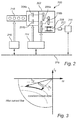
- Fig. 1 is a flow chart outlining the general steps of a method according to an embodiment of the invention. The method of Fig. 1 will be discussed with further reference to Fig. 2 schematically illustrating an electric drive system for a hybrid electric vehicle.
- Fig. 2 illustrates an electric drive system 200 comprising a gear set or a gear box 202.
- the gear box 202 is here illustrated as a dual-clutch transmission gear box 202, comprising a first and a second clutch, 204a, 204b connected to a respective first and second axle, 206a, 206b.
- An electrical machine 208 is operatively connected to the second axle 206b of the gear box 202, which in the present example can be considered to represent the even gears of the gear box 202.
- the gear box 202 is further arranged to receive power from an internal combustion engine (ICE) 210.
- ICE internal combustion engine
- a rechargeable battery 211 is operatively connected to the electrical machine 208 via an inverter and inverter controller unit 212.
- the system further comprises a control unit 214 configured to control the gear box 202 and the electrical machine 208 and an engine control module (ECM) 216 controls the operation of the ICE 210.
- the various control units and modules are connected to a common communication interface, e.g. a CAN bus, for communicating with each other and with other modules in the vehicle in which the drive system is arranged.
- a common communication interface e.g. a CAN bus
- the method outlined in Fig. 1 comprises determining 102 a maximum available braking torque T Max of the electrical machine 208 for a given set of operating conditions based on a maximum power P B,Max 104 that the battery 210 can receive and the total normal power losses P Loss 106 in the electric drive system 200.
- the stator current, I S,Max providing the maximum achievable power dissipation P D,Max in the electrical drive system for a certain shaft torque value is determined 108.
- the maximum available braking torque T Max is thus determined as the sum of the torque required to provide the maximum power to the battery, the normal power losses and the maximum achievable power dissipation, i.e. T Max ⁇ (P B,Max + P Loss + P D,Max ).
- the maximum available braking torque T Max may be determined for a wide range of operating conditions such that a torque map is created, for example in the form of a lookup table, thereby eliminating the need to recalculate the available torques, and also increasing the responsiveness and speed of the system since no online calculations need to be performed to determine the available torque values.
- the different operating conditions to take into consideration may for example comprise the stator winding temperature, the DC voltage to the inverter, the speed of the electrical machine and the output torque from the electrical machine.
- the maximum available braking torque T Max values for different operating conditions may be determined analytically or empirically.
- a stator current Is of the electrical machine that will dissipate the additional power P IS needed while achieving the required braking torque is determined 118, i.e. P IS ⁇ T r - (T(P B,Max ) + T(P Loss )).
- the method comprises determining 120 a stator current I S corresponding to the difference between the requested power dissipation P D,r and the total normal power losses, P Loss .
- the step of determining 108 the stator current, I S,Max , providing the maximum achievable power dissipation P D,Max in the electrical drive system may comprise determining both the electrical machine losses in themselves as well as the inverter losses, since inverter losses are inherent in the electrical machine, and since the inverter losses also depend on the amplitude of the current provided to the electrical machine.
- Fig. 3 is a diagram showing a vector representation of the stator current vector I S for the electrical machine 208.
- the stator current is represented by the d-and q-axis phase currents in a dq-reference frame, where the stator current is limited by a maximum current line to prevent damage to the electrical machine.
- the stator current is determined as a maximum torque per ampere (MTPA) current, I S1 , providing maximum efficiency.
- MTPA maximum torque per ampere
- I S1 maximum torque per ampere
- the stator current I S2 is illustrated as being located along a constant torque line with respect to I S1 , i.e. I S2 provides the same output torque but with a decreased efficiency.
- the current i d is limited to ensure that permanent demagnetization does not occur.
- the requested braking torque is utilized to perform gear synchronization.
- the requested braking torque is a torque required to reduce the speed of the second axle 204b of the gear box 202 in order to facilitate a shift to a higher gear.
Landscapes
- Engineering & Computer Science (AREA)
- Transportation (AREA)
- Mechanical Engineering (AREA)
- Power Engineering (AREA)
- Automation & Control Theory (AREA)
- Electric Propulsion And Braking For Vehicles (AREA)
Abstract
Description
- The present invention relates to a control system for a hybrid electrical vehicle. In particular, the present invention relates to a system and a method for dissipating power in an electrical drive system of a hybrid electrical vehicle.
- A powertrain unit for a hybrid electrical vehicle typically comprises an electrical machine connected to a shaft of the transmission system, such that the power train can be used in pure electric propulsion mode, or in hybrid mode where also the internal combustion engine (ICE) is running and contributing to the propulsion.
- The propulsion system of a hybrid vehicle also comprises a rechargeable battery for providing power to the electrical drive system. The battery may also be charged by the electrical drive system, for example during regenerative braking of the vehicle.
- However, the battery is not always capable of receiving all of the power generated by the electrical machine. For example, if the battery is at or near full capacity, or if the battery temperature is very low, the battery may only be capable of receiving a small amount of power. Accordingly, during some operating conditions excess power generated by the electrical machine cannot be delivered to the battery.
-
US8880259 discloses a motor control apparatus and a method of operating an electric motor in a hybrid vehicle. In particular,US8880259 relates to providing a brake torque in the electrical motor for achieving coast down regenerative braking. In the described motor control apparatus, a motor control unit is configured to select between a normal operation mode and a power dissipation mode based on a state of the battery. During power dissipation motor control operation, power from the brake torque is dissipated in the stator windings of the electric motor without generating any power to the battery. - However, the motor control unit of
US8880259 only addresses two distinct operating modes, normal operation and full power dissipation. Accordingly, an improved system and method which is capable of accommodating a range of different use cases in a hybrid vehicle is desirable. - In view of above-mentioned and other drawbacks of the prior art, it is an object of the present invention to provide an improved method and system for controlling power dissipation in a hybrid electrical vehicle.
- According to a first aspect of the invention, there is provided a method for controlling power dissipation in an electric drive system for a hybrid electrical vehicle, the control system comprising: a gear set or a gear box; an electrical machine connected to an axle of the gear se or gear box; a rechargeable battery operatively connected to the electrical machine; and a control unit configured to control the gear box and the electrical machine; wherein the method comprises the steps of: determining a maximum available braking torque of the electrical machine for a given set of operating conditions based on: a maximum power that the battery can receive; and total normal power losses in the electric drive system; determining the stator current providing the maximum achievable power dissipation in the electrical drive system for a certain shaft torque value; receiving a requested braking torque for the electrical machine, lower than or equal to the maximum available braking torque, or receiving a requested power dissipation lower than or equal to the maximum achievable power dissipation; if a requested braking torque is equal to or lower than the torque required for providing a power corresponding to the sum of the maximum power that the battery can receive and the total power losses, provide the requested braking torque by providing power to the battery corresponding to the difference between the requested braking torque and the total normal power losses; and if the requested braking torque exceeds the torque required for providing a power corresponding to the sum of the maximum power that the battery can receive and the total normal power losses, determine a stator current of the electrical machine that will dissipate this additional power, while achieving the required braking torque; and if a power dissipation is requested, determine a stator current resulting in the requested power dissipation.
- The present invention relates to an electric drive system for a hybrid vehicle where a rechargeable battery is operatively connected to an electrical machine configured to contribute to the propulsion of the vehicle. That the battery is operatively connected to the electrical machine means that the battery may provide power to the electrical machine for generating torque, and that the electrical machine may generate power which is subsequently provided to the battery for charging the battery.
- Even though the control unit is described herein as one unit, the skilled person realizes that a control unit may comprise a plurality of processing units, such as microcontrollers, ASICs, microprocessors and the like. In a vehicle application, the control functionality may be distributed over several control units.
- It is here assumed that the determined maximum available braking torque value is provided to the control functionality of the vehicle responsible for requesting a braking torque or power dissipation from the electric drive system, such that the requested braking torque or power dissipation does not exceed the maximum values.
- When the stator current is determined such that the electrical machine operates at the maximum efficiency, where the stator current is determined as the maximum torque per ampere (MTPA) current with coherent voltage limitation, the available braking torque and/or the possible power dissipation capacity of the electric drive system is limited by the system losses and the power that the battery can receive.
- Accordingly, the present invention is based on the realization that the range of available braking torque or power dissipation values may be extended by determining a stator current for the electrical machine which induces additional losses, i.e. a stator current for which the electrical machine does not operate at its maximum efficiency. Thereby, a greater flexibility in the use of the electric drive system is achieved, as will be further illustrated by examples described in the following.
- The available ranges of both the braking torque and the power dissipation can be extended by recalculating the stator current to allow for extra power losses in the electrical machine and in the converter, compared to the above described situation where the available braking torque is limited by the system power losses and the maximum power that the battery can receive.
- The total normal power losses can be considered to include all losses in the electrical drive system during normal operation of the drive system, such as, but not limited to, normal inverter and electrical machine losses and resistive losses. Accordingly, the maximum achievable power dissipation is a combination of the normal power losses and the additional losses resulting from a modification of the stator current of the electrical machine.
- According to one embodiment of the invention, determining the stator current vector providing the maximum achievable power dissipation in the electrical drive system may comprise determining electrical machine losses and inverter losses for a given stator current. It should be noted that the inverter losses changes as a function of the stator losses, and that to achieve a correct result, the inverter losses for the modified stator current should be included in the determined maximum achievable power dissipation.
- According to one embodiment of the invention, determining a stator current of the electrical machine that will dissipate the additional power needed while achieving the required braking torque may comprise modifying a maximum torque per ampere, MTPA, current.
- The requested torque can be realized with different current vectors along a constant torque line in the current coordinate system. By deviating from the MTPA line, the same torque can be realized with another current vector, and this is how the power dissipation is realized in the motor windings. The maximum amount of power dissipation is limited by the maximum allowed current in the electrical machine, the maximum possible voltage and by thermal and magnetic limitations.
- According to one embodiment of the invention, the method may further comprise determining a plurality of maximum available braking torques of the electrical machine for a range of different operating conditions, and storing the plurality of braking torques. By having access to a stored range of different braking torques for different operating conditions, it is not needed to calculate the available torque for a given operating condition which in turn makes it possible to continuously have access to a correct value of the available braking torque. The different braking torques can for example be stored in a database in an appropriate format.
- According to one embodiment of the invention, the operating conditions may comprise stator winding temperature, DC voltage to the inverter, speed of the electrical machine and/or output torque from the electrical machine. All of the described operating conditions influence the maximum available braking torque of the electrical machine. For example, the stator winding temperature influences the winding resistance which in turn influences the relation between winding current and power loss in the windings.
- According to one embodiment of the invention, the total normal power losses in the electric drive system comprise losses from the electrical machine and from power consuming units of the vehicle. The electrical drive system losses may for example comprise inverter losses, i.e. switching and conduction losses in power electronic transistors, resistive electrical machine stator losses, i.e. copper losses, and core and drag losses of the electrical machine, i.e. iron losses and mechanical drag losses. The power consuming unit may for example be an air conditioning system. The normal power losses may also comprise dc-dc converter losses. Moreover, in cases where the desired power dissipation exceeds the maximum available power dissipation, it is possible to utilize controllable additional loads for dissipating the additional power.
- According to one embodiment of the invention, the requested braking torque may be utilized to perform gear synchronization. An advantage of knowing the available torque is that a simpler rpm regulator can be used without the need for windup compensation or the handling of residual errors which could result from an unrealized requested torque. This in turn leads to a simplified calibration and verification in the overall control system. Moreover, the simplified rpm regulation may also lead to increased communication rates in a distributed control system.
- In particular, in one embodiment of the invention the requested braking torque is a torque required to reduce the speed of the axle of the gear box in order to facilitate a shift to a higher gear.
- According to one embodiment of the invention, the requested braking torque may be utilized to increase a torque window for performing electrical braking of the vehicle. This has the advantage that the maximum available amount of electrical braking can be increased by utilizing the available braking torque of the electrical machine.
- According to one embodiment of the invention, the requested power dissipation may be used to selectively control additional heating in the electrical machine and/or in the inverter, which in turn can be used to reduce the viscosity of coolant media which may be desirable at very low temperatures.
- According to a second aspect of the invention, there is provided a control system for controlling power dissipation in an electric drive system for a hybrid electrical vehicle comprising: a gear set or a gear box; an electrical machine connected to an axle of the gear se or gear box; and rechargeable battery operatively connected to the electrical machine via an inverter, the control system comprising a control unit configured to control the gear box and the electrical machine; wherein the control unit is configured to: determine a maximum available braking torque of the electrical machine for a given set of operating conditions based on: a maximum power that the battery can receive; and total normal power losses in the electric drive system; determine the stator current providing the maximum achievable power dissipation in the electrical drive system for a certain shaft torque value; receive a requested braking torque for the electrical machine, lower than or equal to the maximum available braking torque, or receiving a requested power dissipation lower than or equal to the maximum achievable power dissipation; if a requested braking torque is equal to or lower than the torque required for providing a power corresponding to the sum of the maximum power that the battery can receive and the total power losses, provide the requested braking torque by providing power to the battery corresponding to the difference between the requested braking torque and the total normal power losses; and if the required braking torque exceeds the torque required for providing a power corresponding to the sum of the maximum power that the battery can receive and the total normal power losses, determine a stator current of the electrical machine that will dissipate the additional power needed while still achieving the required braking torque; and if a power dissipation is requested, determine a stator current resulting in the requested power dissipation.
- According to one embodiment of the invention, the gear box may be a dual clutch transmission gear box, wherein the electrical machine is operatively connected to an axle of one of the two clutches, and where the other axle is connected to the internal combustion engine (ICE). Thereby, the gear box can be operated in pure electric propulsion mode, in hybrid mode or in ICE mode, by controlling the dual clutches. This in turn allows the electrical machine to be utilized for different purposes in the different modes.
- Effects and features of the second aspect of the invention are largely analogous to those described above in connection with the first aspect of the invention.
- There is also provided a method for controlling power dissipation in an electric drive system for a hybrid electrical vehicle, the control system comprising: a gear set or a gear box; an electrical machine connected to an axle of the gear set or gear box; a rechargeable battery operatively connected to the electrical machine; and a control unit configured to control the gear box and the electrical machine; wherein the method comprises the steps of: determining a maximum available braking torque of the electrical machine for a given set of operating conditions based on: a maximum power that the battery can receive; and total normal power losses in the electric drive system; receiving a requested braking torque for the electrical machine, lower than or equal to the maximum available braking torque, and if the requested braking torque is equal to or lower than the torque required for providing a power corresponding to the sum of the maximum power that the battery can receive and the total power losses, providing the requested braking torque by providing power to the battery corresponding to the difference between the requested braking torque and the total normal power losses; and if the requested braking torque exceeds the torque required for providing a power corresponding to the sum of the maximum power that the battery can receive and the total normal power losses, determining a stator current of the electrical machine that will dissipate the additional power needed while achieving the required braking torque.
- There is also provided a method for controlling power dissipation in an electric drive system for a hybrid electrical vehicle, the control system comprising: gear set or a gear box; an electrical machine connected to an axle of the gear set or gear box; a rechargeable battery operatively connected to the electrical machine; and a control unit configured to control the gear box and the electrical machine; wherein the method comprises the steps of: determining the stator current providing a maximum achievable power dissipation in the electrical drive system for a certain shaft torque value; receiving a requested power dissipation lower than or equal to the sum of the maximum achievable power dissipation in the electrical drive system and the total normal power losses; and determining a stator current corresponding to the difference between the requested power dissipation and the total normal power losses.
- Further features of, and advantages with, the present invention will become apparent when studying the appended claims and the following description. The skilled person realize that different features of the present invention may be combined to create embodiments other than those described in the following, without departing from the scope of the present invention.
- These and other aspects of the present invention will now be described in more detail, with reference to the appended drawings showing an example embodiment of the invention, wherein:
-
Fig. 1 is a flow chart outlining the general steps of a method according to an embodiment of the invention; -
Fig. 2 schematically illustrates an electric drive system for a hybrid electric vehicle according to an embodiment of the invention; and -
Fig. 3 is a graph schematically illustrating stator current for an electrical machine according to embodiments of the invention. - In the present detailed description, various embodiments of the method and system according to the present invention are mainly described with reference to an electric drive system for a hybrid vehicle comprising a dual clutch transmission. However, the general concept of the invention is equally applicable to hybrid drive systems utilizing other transmission configurations.
-
Fig. 1 is a flow chart outlining the general steps of a method according to an embodiment of the invention. The method ofFig. 1 will be discussed with further reference toFig. 2 schematically illustrating an electric drive system for a hybrid electric vehicle. -
Fig. 2 illustrates anelectric drive system 200 comprising a gear set or agear box 202. Thegear box 202 is here illustrated as a dual-clutchtransmission gear box 202, comprising a first and a second clutch, 204a, 204b connected to a respective first and second axle, 206a, 206b. Anelectrical machine 208 is operatively connected to thesecond axle 206b of thegear box 202, which in the present example can be considered to represent the even gears of thegear box 202. Thegear box 202 is further arranged to receive power from an internal combustion engine (ICE) 210. Arechargeable battery 211 is operatively connected to theelectrical machine 208 via an inverter and inverter controller unit 212. - The system further comprises a
control unit 214 configured to control thegear box 202 and theelectrical machine 208 and an engine control module (ECM) 216 controls the operation of theICE 210. The various control units and modules are connected to a common communication interface, e.g. a CAN bus, for communicating with each other and with other modules in the vehicle in which the drive system is arranged. However, the skilled person realizes that the described functionality can be achieved in many different ways by using one or more dedicated or general purpose control units. - The method outlined in
Fig. 1 comprises determining 102 a maximum available braking torque TMax of theelectrical machine 208 for a given set of operating conditions based on amaximum power P B,Max 104 that thebattery 210 can receive and the total normalpower losses P Loss 106 in theelectric drive system 200. Next, the stator current, IS,Max, providing the maximum achievable power dissipation PD,Max in the electrical drive system for a certain shaft torque value is determined 108. - The maximum available braking torque TMax is thus determined as the sum of the torque required to provide the maximum power to the battery, the normal power losses and the maximum achievable power dissipation, i.e. TMax ∼ (PB,Max + PLoss + PD,Max).
- Next, the method comprises receiving 110 a requested braking torque Tr for the electrical machine, lower than or equal to the maximum available braking torque TMax, or receiving 112 a requested power dissipation PD,r lower than or equal to the sum of the maximum achievable power dissipation in the electrical drive system, PD,EM, and the total normal power losses PLoss. Since the maximum available braking torque has been determined for a given set of operating conditions, this value can be communicated to other functionality of the vehicle such that the requested braking torque Tr does not exceed the available torque TMax, for the given set of operating conditions. Furthermore, a requested power dissipation PD,r is limited by the maximum available power dissipation PD,Max = PD,EM + PLoss.
- Moreover, the maximum available braking torque TMax may be determined for a wide range of operating conditions such that a torque map is created, for example in the form of a lookup table, thereby eliminating the need to recalculate the available torques, and also increasing the responsiveness and speed of the system since no online calculations need to be performed to determine the available torque values. The different operating conditions to take into consideration may for example comprise the stator winding temperature, the DC voltage to the inverter, the speed of the electrical machine and the output torque from the electrical machine. Furthermore, the maximum available braking torque TMax values for different operating conditions may be determined analytically or empirically.
- Next, it is determined 114 if the requested braking torque Tr is equal to or lower than the torque required for providing a power corresponding to the sum of the maximum power that the battery can receive PB,Max and the total power losses PLoss. If that is the case, the requested braking torque Tr is provided by providing 116 power to the battery corresponding to the difference between the requested braking torque and the total normal power losses, i.e. PB = P(Tr) - PLoss.
- On the other hand, if it is determined 114 that the requested braking torque exceeds the torque required for providing a power corresponding to the sum of the maximum power that the battery can receive and the total normal power losses, a stator current Is of the electrical machine that will dissipate the additional power PIS needed while achieving the required braking torque is determined 118, i.e. PIS ∼ Tr - (T(PB,Max) + T(PLoss)).
- If there is a request is for dissipation of additional power, PD,r, the method comprises determining 120 a stator current IS corresponding to the difference between the requested power dissipation PD,r and the total normal power losses, PLoss.
- The step of determining 108 the stator current, IS,Max, providing the maximum achievable power dissipation PD,Max in the electrical drive system may comprise determining both the electrical machine losses in themselves as well as the inverter losses, since inverter losses are inherent in the electrical machine, and since the inverter losses also depend on the amplitude of the current provided to the electrical machine.
-
Fig. 3 is a diagram showing a vector representation of the stator current vector IS for theelectrical machine 208. The stator current is represented by the d-and q-axis phase currents in a dq-reference frame, where the stator current is limited by a maximum current line to prevent damage to the electrical machine. In a normal operating mode where no additional power dissipation is required in the electrical machine, the stator current is determined as a maximum torque per ampere (MTPA) current, IS1, providing maximum efficiency. To increase the possible power dissipation in the electrical machine, the stator current is recalculated. The stator current IS2 is illustrated as being located along a constant torque line with respect to IS1, i.e. IS2 provides the same output torque but with a decreased efficiency. - For machine speed-and torque-levels covering the entire operating range, the d-axis and q-axis current resulting in the highest achievable stator current (MAPT-Maximum Ampere Per Torque) and resistive losses in the electric machine stator is calculated, where the considered resistive losses Pcu are defined by

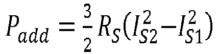
- The additional losses Padd made possible by modifying the stator current IS1 can be approximately estimated by the increased resistive losses and determined as
- In one embodiment of the invention, the requested braking torque is utilized to perform gear synchronization. In particular, the requested braking torque is a torque required to reduce the speed of the
second axle 204b of thegear box 202 in order to facilitate a shift to a higher gear. - Even though the invention has been described with reference to specific exemplifying embodiments thereof, many different alterations, modifications and the like will become apparent for those skilled in the art. Also, it should be noted that parts of the method and system may be omitted, interchanged or arranged in various ways, the method and system yet being able to perform the functionality of the present invention.
- Additionally, variations to the disclosed embodiments can be understood and effected by the skilled person in practicing the claimed invention, from a study of the drawings, the disclosure, and the appended claims. In the claims, the word "comprising" does not exclude other elements or steps, and the indefinite article "a" or "an" does not exclude a plurality. The mere fact that certain measures are recited in mutually different dependent claims does not indicate that a combination of these measures cannot be used to advantage.
Claims (15)
- A method for controlling power dissipation in an electric drive system for a hybrid electrical vehicle, the control system comprising:a gear set or a gear box (202);an electrical machine (208) connected to an axle of the gear set or gear box;a rechargeable battery (211) operatively connected to the electrical machine; anda control unit (214) configured to control the gear box and the electrical machine; wherein the method comprises the steps of:determining (102) a maximum available braking torque of the electrical machine for a given set of operating conditions based on:- a maximum power that the battery can receive (104); and- total normal power losses in the electric drive system (106);- determining (108) the stator current providing a maximum achievable power dissipation in the electrical drive system for a certain shaft torque value;receiving (110) a requested braking torque for the electrical machine, lower than or equal to the maximum available braking torque, or receiving (112) a requested power dissipation lower than or equal to a maximum achievable power dissipation in the electrical drive system;if the requested braking torque is equal to or lower than the torque required for providing a power corresponding to the sum of the maximum power that the battery can receive and the total power losses, providing the requested braking torque by providing (116) power to the battery corresponding to the difference between the requested braking torque and the total normal power losses; andif the requested braking torque exceeds the torque required for providing a power corresponding to the sum of the maximum power that the battery can receive and the total normal power losses, determining (118) a stator current of the electrical machine that will dissipate the additional power needed while achieving the required braking torque; andif a power dissipation is requested, determining (120) a stator current resulting in the requested power dissipation.
- The method according to claim 1, wherein determining the stator current providing the maximum achievable power dissipation in the electrical drive system comprises determining electrical machine losses and inverter losses
- The method according to any one of the preceding claims, wherein determining a stator current vector of the electrical machine that will dissipate the additional power needed while achieving the required braking torque comprises modifying a maximum torque per ampere, MTPA, stator current along a constant torque line.
- The method according to any one of the preceding claims, further comprising determining a plurality of maximum available braking torques of the electrical machine for a range of different operating conditions, and storing the plurality of available braking torques.
- The method according to any one of the preceding claims, wherein the operating conditions comprises stator winding temperature, DC voltage to the inverter, speed of the electrical machine and output torque from the electrical machine.
- The method according to any one of the preceding claims, wherein the total normal power losses in the electric drive system comprises losses from the electrical machine and from power consuming units of the vehicle.
- The method according to any one of the preceding claims, wherein the requested braking torque is utilized to perform gear synchronization.
- The method according to claim 7, wherein the requested braking torque is a torque required to reduce the speed of the axle of the gear box in order to facilitate a shift to a higher gear.
- The method according to any one of the preceding claims, wherein the requested braking torque is utilized to increase a torque window for performing electrical braking of the vehicle.
- The method according to any one of the preceding claims, wherein the requested power dissipation is used to selectively control additional heating in the electrical machine and/or in the inverter.
- A control system for controlling power dissipation in an electric drive system for a hybrid electrical vehicle comprising:a gear set or a gear box (202);an electrical machine (208) connected to an axle of the gear se or gear box; and a rechargeable battery (211) operatively connected to the electrical machine via an inverter, the control system comprising;a control unit (214) configured to control the gear box and the electrical machine; wherein the control unit is configured to:determine a maximum available braking torque of the electrical machine for a given set of operating conditions based on:- a maximum power that the battery can receive; and- total normal power losses in the electric drive system;- determine the stator current providing the maximum achievable power dissipation in the electrical drive system for a certain shaft torque value;receive a requested braking torque for the electrical machine, lower than or equal to the maximum available braking torque, or receiving a requested power dissipation lower than or equal to the maximum achievable power dissipation;if a requested braking torque is equal to or lower than the torque required for providing a power corresponding to the sum of the maximum power that the battery can receive and the total power losses, provide the requested braking torque by providing power to the battery corresponding to the difference between the requested braking torque and the total normal power losses; andif the required braking torque exceeds the torque required for providing a power corresponding to the sum of the maximum power that the battery can receive and the total normal power losses, determine a stator current of the electrical machine that will dissipate the additional power needed while still achieving the required braking torque; andif a power dissipation is requested, determine a stator current resulting in the requested power dissipation.
- The control system according to claim 11, wherein the gear box is a dual clutch transmission gear box, wherein the electrical machine is operatively connected to an axle of one of the two clutches.
- The control system according to claim 11 or 12, wherein the control unit is further configured to determine the stator current providing the maximum achievable power dissipation in the electrical drive system by determining electrical machine losses and inverter losses
- The control system according to any one of claims 11 to 13, wherein the control unit is further configured to determine a stator current of the electrical machine that will dissipate the additional power needed while achieving the required braking torque by modifying a maximum torque per ampere, MTPA, stator current along a constant torque line.
- The control system according to any one of claims 11 to 14, wherein the control unit is further configured to determine a plurality of maximum available braking torques of the electrical machine for a range of different operating conditions, and to store the plurality of available braking torques.
Priority Applications (3)
| Application Number | Priority Date | Filing Date | Title |
|---|---|---|---|
| EP16178247.9A EP3266643A1 (en) | 2016-07-06 | 2016-07-06 | Power dissipating torque controller |
| US15/634,208 US20180009320A1 (en) | 2016-07-06 | 2017-06-27 | Power dissipating torque controller |
| CN201710514681.7A CN107585059A (en) | 2016-07-06 | 2017-06-29 | Power Consumption Torque Controller |
Applications Claiming Priority (1)
| Application Number | Priority Date | Filing Date | Title |
|---|---|---|---|
| EP16178247.9A EP3266643A1 (en) | 2016-07-06 | 2016-07-06 | Power dissipating torque controller |
Publications (1)
| Publication Number | Publication Date |
|---|---|
| EP3266643A1 true EP3266643A1 (en) | 2018-01-10 |
Family
ID=56368888
Family Applications (1)
| Application Number | Title | Priority Date | Filing Date |
|---|---|---|---|
| EP16178247.9A Withdrawn EP3266643A1 (en) | 2016-07-06 | 2016-07-06 | Power dissipating torque controller |
Country Status (3)
| Country | Link |
|---|---|
| US (1) | US20180009320A1 (en) |
| EP (1) | EP3266643A1 (en) |
| CN (1) | CN107585059A (en) |
Families Citing this family (2)
| Publication number | Priority date | Publication date | Assignee | Title |
|---|---|---|---|---|
| DE102017212191A1 (en) * | 2017-07-17 | 2019-01-17 | Audi Ag | heater |
| CN109367403B (en) * | 2018-11-27 | 2021-01-05 | 奇瑞汽车股份有限公司 | Motor torque control method and device for hybrid electric vehicle and storage medium |
Citations (4)
| Publication number | Priority date | Publication date | Assignee | Title |
|---|---|---|---|---|
| US6121740A (en) * | 1994-06-27 | 2000-09-19 | Ford Global Technologies, Inc. | Control of regeneration energy from an electric motor |
| DE102012024573A1 (en) * | 2012-12-15 | 2014-06-18 | Daimler Ag | Method for operating internal combustion engine of electric car, involves controlling prime mover in state in which maximum producible electrical power from current braking torque is larger than electrical power receptible in energy store |
| US8880259B2 (en) | 2011-12-13 | 2014-11-04 | Chrysler Group Llc | Electric power dissipation control |
| US20150072830A1 (en) * | 2012-04-02 | 2015-03-12 | Daimler Ag | Hybrid Electric Vehicle Control Device |
Family Cites Families (9)
| Publication number | Priority date | Publication date | Assignee | Title |
|---|---|---|---|---|
| US8118703B2 (en) * | 2006-12-01 | 2012-02-21 | Chrysler Group Llc | Hybrid transmission having synchronizers |
| JP4240149B1 (en) * | 2008-02-14 | 2009-03-18 | トヨタ自動車株式会社 | Motor drive device and hybrid drive device |
| JP5664782B2 (en) * | 2011-07-11 | 2015-02-04 | トヨタ自動車株式会社 | Brake system, actuator control device |
| BR112015000006B1 (en) * | 2012-07-04 | 2021-06-08 | Volvo Truck Corporation | method for controlling a hybrid vehicle-vehicle electrical system using such a method |
| JP5933826B2 (en) * | 2013-04-23 | 2016-06-15 | 三菱電機株式会社 | Control device and control method for hybrid vehicle |
| JP5994934B2 (en) * | 2013-05-13 | 2016-09-21 | トヨタ自動車株式会社 | Hybrid vehicle drive device |
| US9174631B2 (en) * | 2013-06-24 | 2015-11-03 | GM Global Technology Operations LLC | Method and apparatus for controlling transmission shifting in a multi-mode powertrain system |
| US20150007269A1 (en) * | 2013-06-27 | 2015-01-01 | International Business Machines Corporation | Delegating authentication for a web service |
| JP6267485B2 (en) * | 2013-10-30 | 2018-01-24 | 株式会社Subaru | Control device for four-wheel drive hybrid vehicle |
-
2016
- 2016-07-06 EP EP16178247.9A patent/EP3266643A1/en not_active Withdrawn
-
2017
- 2017-06-27 US US15/634,208 patent/US20180009320A1/en not_active Abandoned
- 2017-06-29 CN CN201710514681.7A patent/CN107585059A/en active Pending
Patent Citations (4)
| Publication number | Priority date | Publication date | Assignee | Title |
|---|---|---|---|---|
| US6121740A (en) * | 1994-06-27 | 2000-09-19 | Ford Global Technologies, Inc. | Control of regeneration energy from an electric motor |
| US8880259B2 (en) | 2011-12-13 | 2014-11-04 | Chrysler Group Llc | Electric power dissipation control |
| US20150072830A1 (en) * | 2012-04-02 | 2015-03-12 | Daimler Ag | Hybrid Electric Vehicle Control Device |
| DE102012024573A1 (en) * | 2012-12-15 | 2014-06-18 | Daimler Ag | Method for operating internal combustion engine of electric car, involves controlling prime mover in state in which maximum producible electrical power from current braking torque is larger than electrical power receptible in energy store |
Also Published As
| Publication number | Publication date |
|---|---|
| CN107585059A (en) | 2018-01-16 |
| US20180009320A1 (en) | 2018-01-11 |
Similar Documents
| Publication | Publication Date | Title |
|---|---|---|
| US10246080B2 (en) | Hybrid vehicle control apparatus | |
| CN107150595B (en) | vehicle | |
| CN104159774B (en) | Electrical power dissipation control method and device | |
| US6831429B2 (en) | Prediction of available torque and power from battery-powered traction motor | |
| CN112769373B (en) | Electric propulsion system and method for optimizing driving operation of an electric propulsion system | |
| WO2005069478A1 (en) | Power supply apparatus, motor drive control method using the same and motor vehicle having the same mounted thereon | |
| US9022165B2 (en) | Vehicle lubrication flow control | |
| US8928263B2 (en) | Control apparatus in motor drive system and method of controlling motor drive system | |
| AU2014241859B2 (en) | System and method for compensation of turbo lag in hybrid vehicles | |
| JP2016073039A (en) | Electric vehicle control device | |
| US20150149005A1 (en) | Torque monitoring system and method | |
| JP2016208687A (en) | Electric vehicle | |
| US9616768B2 (en) | Electrical machine control method and apparatus | |
| CN113794416A (en) | Motor control method, apparatus, power system, vehicle, and storage medium | |
| EP3266643A1 (en) | Power dissipating torque controller | |
| US20180134277A1 (en) | Hybrid vehicle | |
| JP6825043B2 (en) | Hybrid vehicle control device | |
| US20190118797A1 (en) | Method for controlling hybrid vehicle | |
| US12447864B2 (en) | Electrified vehicle with wound rotor synchronous electric machine controlled to heat battery | |
| JP6543745B2 (en) | Control device for hybrid vehicle | |
| US20230083115A1 (en) | Regenerative energy dissipation control in a multichannel drive | |
| JP2016208686A (en) | Electric vehicle | |
| JP2009219332A (en) | Superconducting motor device and electric vehicle | |
| RU2798447C1 (en) | Electric vehicle drive and method of controlling it | |
| KR101823076B1 (en) | Integrated starter generator system and controlling method thereof |
Legal Events
| Date | Code | Title | Description |
|---|---|---|---|
| PUAI | Public reference made under article 153(3) epc to a published international application that has entered the european phase |
Free format text: ORIGINAL CODE: 0009012 |
|
| AK | Designated contracting states |
Kind code of ref document: A1 Designated state(s): AL AT BE BG CH CY CZ DE DK EE ES FI FR GB GR HR HU IE IS IT LI LT LU LV MC MK MT NL NO PL PT RO RS SE SI SK SM TR |
|
| AX | Request for extension of the european patent |
Extension state: BA ME |
|
| 17P | Request for examination filed |
Effective date: 20180710 |
|
| RBV | Designated contracting states (corrected) |
Designated state(s): AL AT BE BG CH CY CZ DE DK EE ES FI FR GB GR HR HU IE IS IT LI LT LU LV MC MK MT NL NO PL PT RO RS SE SI SK SM TR |
|
| 17Q | First examination report despatched |
Effective date: 20190121 |
|
| STAA | Information on the status of an ep patent application or granted ep patent |
Free format text: STATUS: THE APPLICATION HAS BEEN WITHDRAWN |
|
| 18W | Application withdrawn |
Effective date: 20190701 |