EP3266609A1 - Method for producing components for motor-vehicle structures, having a hybrid structure made of light alloy and plastic material - Google Patents
Method for producing components for motor-vehicle structures, having a hybrid structure made of light alloy and plastic material Download PDFInfo
- Publication number
- EP3266609A1 EP3266609A1 EP16178085.3A EP16178085A EP3266609A1 EP 3266609 A1 EP3266609 A1 EP 3266609A1 EP 16178085 A EP16178085 A EP 16178085A EP 3266609 A1 EP3266609 A1 EP 3266609A1
- Authority
- EP
- European Patent Office
- Prior art keywords
- sheet
- plastic material
- hybrid panel
- light alloy
- forming surface
- Prior art date
- Legal status (The legal status is an assumption and is not a legal conclusion. Google has not performed a legal analysis and makes no representation as to the accuracy of the status listed.)
- Granted
Links
Images



Classifications
-
- B—PERFORMING OPERATIONS; TRANSPORTING
- B21—MECHANICAL METAL-WORKING WITHOUT ESSENTIALLY REMOVING MATERIAL; PUNCHING METAL
- B21D—WORKING OR PROCESSING OF SHEET METAL OR METAL TUBES, RODS OR PROFILES WITHOUT ESSENTIALLY REMOVING MATERIAL; PUNCHING METAL
- B21D26/00—Shaping without cutting otherwise than using rigid devices or tools or yieldable or resilient pads, i.e. applying fluid pressure or magnetic forces
- B21D26/02—Shaping without cutting otherwise than using rigid devices or tools or yieldable or resilient pads, i.e. applying fluid pressure or magnetic forces by applying fluid pressure
- B21D26/021—Deforming sheet bodies
-
- B—PERFORMING OPERATIONS; TRANSPORTING
- B21—MECHANICAL METAL-WORKING WITHOUT ESSENTIALLY REMOVING MATERIAL; PUNCHING METAL
- B21D—WORKING OR PROCESSING OF SHEET METAL OR METAL TUBES, RODS OR PROFILES WITHOUT ESSENTIALLY REMOVING MATERIAL; PUNCHING METAL
- B21D26/00—Shaping without cutting otherwise than using rigid devices or tools or yieldable or resilient pads, i.e. applying fluid pressure or magnetic forces
- B21D26/02—Shaping without cutting otherwise than using rigid devices or tools or yieldable or resilient pads, i.e. applying fluid pressure or magnetic forces by applying fluid pressure
- B21D26/053—Shaping without cutting otherwise than using rigid devices or tools or yieldable or resilient pads, i.e. applying fluid pressure or magnetic forces by applying fluid pressure characterised by the material of the blanks
- B21D26/059—Layered blanks
-
- B—PERFORMING OPERATIONS; TRANSPORTING
- B21—MECHANICAL METAL-WORKING WITHOUT ESSENTIALLY REMOVING MATERIAL; PUNCHING METAL
- B21D—WORKING OR PROCESSING OF SHEET METAL OR METAL TUBES, RODS OR PROFILES WITHOUT ESSENTIALLY REMOVING MATERIAL; PUNCHING METAL
- B21D53/00—Making other particular articles
- B21D53/88—Making other particular articles other parts for vehicles, e.g. cowlings, mudguards
-
- B—PERFORMING OPERATIONS; TRANSPORTING
- B32—LAYERED PRODUCTS
- B32B—LAYERED PRODUCTS, i.e. PRODUCTS BUILT-UP OF STRATA OF FLAT OR NON-FLAT, e.g. CELLULAR OR HONEYCOMB, FORM
- B32B15/00—Layered products comprising a layer of metal
- B32B15/04—Layered products comprising a layer of metal comprising metal as the main or only constituent of a layer, which is next to another layer of the same or of a different material
- B32B15/08—Layered products comprising a layer of metal comprising metal as the main or only constituent of a layer, which is next to another layer of the same or of a different material of synthetic resin
-
- B—PERFORMING OPERATIONS; TRANSPORTING
- B32—LAYERED PRODUCTS
- B32B—LAYERED PRODUCTS, i.e. PRODUCTS BUILT-UP OF STRATA OF FLAT OR NON-FLAT, e.g. CELLULAR OR HONEYCOMB, FORM
- B32B15/00—Layered products comprising a layer of metal
- B32B15/04—Layered products comprising a layer of metal comprising metal as the main or only constituent of a layer, which is next to another layer of the same or of a different material
- B32B15/08—Layered products comprising a layer of metal comprising metal as the main or only constituent of a layer, which is next to another layer of the same or of a different material of synthetic resin
- B32B15/085—Layered products comprising a layer of metal comprising metal as the main or only constituent of a layer, which is next to another layer of the same or of a different material of synthetic resin comprising polyolefins
-
- B—PERFORMING OPERATIONS; TRANSPORTING
- B32—LAYERED PRODUCTS
- B32B—LAYERED PRODUCTS, i.e. PRODUCTS BUILT-UP OF STRATA OF FLAT OR NON-FLAT, e.g. CELLULAR OR HONEYCOMB, FORM
- B32B15/00—Layered products comprising a layer of metal
- B32B15/04—Layered products comprising a layer of metal comprising metal as the main or only constituent of a layer, which is next to another layer of the same or of a different material
- B32B15/08—Layered products comprising a layer of metal comprising metal as the main or only constituent of a layer, which is next to another layer of the same or of a different material of synthetic resin
- B32B15/088—Layered products comprising a layer of metal comprising metal as the main or only constituent of a layer, which is next to another layer of the same or of a different material of synthetic resin comprising polyamides
-
- B—PERFORMING OPERATIONS; TRANSPORTING
- B32—LAYERED PRODUCTS
- B32B—LAYERED PRODUCTS, i.e. PRODUCTS BUILT-UP OF STRATA OF FLAT OR NON-FLAT, e.g. CELLULAR OR HONEYCOMB, FORM
- B32B15/00—Layered products comprising a layer of metal
- B32B15/14—Layered products comprising a layer of metal next to a fibrous or filamentary layer
-
- B—PERFORMING OPERATIONS; TRANSPORTING
- B32—LAYERED PRODUCTS
- B32B—LAYERED PRODUCTS, i.e. PRODUCTS BUILT-UP OF STRATA OF FLAT OR NON-FLAT, e.g. CELLULAR OR HONEYCOMB, FORM
- B32B15/00—Layered products comprising a layer of metal
- B32B15/20—Layered products comprising a layer of metal comprising aluminium or copper
-
- B—PERFORMING OPERATIONS; TRANSPORTING
- B32—LAYERED PRODUCTS
- B32B—LAYERED PRODUCTS, i.e. PRODUCTS BUILT-UP OF STRATA OF FLAT OR NON-FLAT, e.g. CELLULAR OR HONEYCOMB, FORM
- B32B27/00—Layered products comprising a layer of synthetic resin
- B32B27/32—Layered products comprising a layer of synthetic resin comprising polyolefins
-
- B—PERFORMING OPERATIONS; TRANSPORTING
- B32—LAYERED PRODUCTS
- B32B—LAYERED PRODUCTS, i.e. PRODUCTS BUILT-UP OF STRATA OF FLAT OR NON-FLAT, e.g. CELLULAR OR HONEYCOMB, FORM
- B32B27/00—Layered products comprising a layer of synthetic resin
- B32B27/34—Layered products comprising a layer of synthetic resin comprising polyamides
-
- B—PERFORMING OPERATIONS; TRANSPORTING
- B32—LAYERED PRODUCTS
- B32B—LAYERED PRODUCTS, i.e. PRODUCTS BUILT-UP OF STRATA OF FLAT OR NON-FLAT, e.g. CELLULAR OR HONEYCOMB, FORM
- B32B7/00—Layered products characterised by the relation between layers; Layered products characterised by the relative orientation of features between layers, or by the relative values of a measurable parameter between layers, i.e. products comprising layers having different physical, chemical or physicochemical properties; Layered products characterised by the interconnection of layers
- B32B7/04—Interconnection of layers
-
- B—PERFORMING OPERATIONS; TRANSPORTING
- B29—WORKING OF PLASTICS; WORKING OF SUBSTANCES IN A PLASTIC STATE IN GENERAL
- B29K—INDEXING SCHEME ASSOCIATED WITH SUBCLASSES B29B, B29C OR B29D, RELATING TO MOULDING MATERIALS OR TO MATERIALS FOR MOULDS, REINFORCEMENTS, FILLERS OR PREFORMED PARTS, e.g. INSERTS
- B29K2307/00—Use of elements other than metals as reinforcement
- B29K2307/04—Carbon
-
- B—PERFORMING OPERATIONS; TRANSPORTING
- B29—WORKING OF PLASTICS; WORKING OF SUBSTANCES IN A PLASTIC STATE IN GENERAL
- B29K—INDEXING SCHEME ASSOCIATED WITH SUBCLASSES B29B, B29C OR B29D, RELATING TO MOULDING MATERIALS OR TO MATERIALS FOR MOULDS, REINFORCEMENTS, FILLERS OR PREFORMED PARTS, e.g. INSERTS
- B29K2309/00—Use of inorganic materials not provided for in groups B29K2303/00 - B29K2307/00, as reinforcement
- B29K2309/08—Glass
-
- B—PERFORMING OPERATIONS; TRANSPORTING
- B29—WORKING OF PLASTICS; WORKING OF SUBSTANCES IN A PLASTIC STATE IN GENERAL
- B29K—INDEXING SCHEME ASSOCIATED WITH SUBCLASSES B29B, B29C OR B29D, RELATING TO MOULDING MATERIALS OR TO MATERIALS FOR MOULDS, REINFORCEMENTS, FILLERS OR PREFORMED PARTS, e.g. INSERTS
- B29K2623/00—Use of polyalkenes or derivatives thereof for preformed parts, e.g. for inserts
- B29K2623/10—Polymers of propylene
- B29K2623/12—PP, i.e. polypropylene
-
- B—PERFORMING OPERATIONS; TRANSPORTING
- B29—WORKING OF PLASTICS; WORKING OF SUBSTANCES IN A PLASTIC STATE IN GENERAL
- B29K—INDEXING SCHEME ASSOCIATED WITH SUBCLASSES B29B, B29C OR B29D, RELATING TO MOULDING MATERIALS OR TO MATERIALS FOR MOULDS, REINFORCEMENTS, FILLERS OR PREFORMED PARTS, e.g. INSERTS
- B29K2677/00—Use of PA, i.e. polyamides, e.g. polyesteramides or derivatives thereof, for preformed parts, e.g. for inserts
-
- B—PERFORMING OPERATIONS; TRANSPORTING
- B29—WORKING OF PLASTICS; WORKING OF SUBSTANCES IN A PLASTIC STATE IN GENERAL
- B29K—INDEXING SCHEME ASSOCIATED WITH SUBCLASSES B29B, B29C OR B29D, RELATING TO MOULDING MATERIALS OR TO MATERIALS FOR MOULDS, REINFORCEMENTS, FILLERS OR PREFORMED PARTS, e.g. INSERTS
- B29K2705/00—Use of metals, their alloys or their compounds, for preformed parts, e.g. for inserts
-
- B—PERFORMING OPERATIONS; TRANSPORTING
- B29—WORKING OF PLASTICS; WORKING OF SUBSTANCES IN A PLASTIC STATE IN GENERAL
- B29L—INDEXING SCHEME ASSOCIATED WITH SUBCLASS B29C, RELATING TO PARTICULAR ARTICLES
- B29L2031/00—Other particular articles
- B29L2031/30—Vehicles, e.g. ships or aircraft, or body parts thereof
- B29L2031/3002—Superstructures characterized by combining metal and plastics, i.e. hybrid parts
-
- B—PERFORMING OPERATIONS; TRANSPORTING
- B32—LAYERED PRODUCTS
- B32B—LAYERED PRODUCTS, i.e. PRODUCTS BUILT-UP OF STRATA OF FLAT OR NON-FLAT, e.g. CELLULAR OR HONEYCOMB, FORM
- B32B2250/00—Layers arrangement
- B32B2250/40—Symmetrical or sandwich layers, e.g. ABA, ABCBA, ABCCBA
-
- B—PERFORMING OPERATIONS; TRANSPORTING
- B32—LAYERED PRODUCTS
- B32B—LAYERED PRODUCTS, i.e. PRODUCTS BUILT-UP OF STRATA OF FLAT OR NON-FLAT, e.g. CELLULAR OR HONEYCOMB, FORM
- B32B2260/00—Layered product comprising an impregnated, embedded, or bonded layer wherein the layer comprises an impregnation, embedding, or binder material
- B32B2260/02—Composition of the impregnated, bonded or embedded layer
- B32B2260/021—Fibrous or filamentary layer
-
- B—PERFORMING OPERATIONS; TRANSPORTING
- B32—LAYERED PRODUCTS
- B32B—LAYERED PRODUCTS, i.e. PRODUCTS BUILT-UP OF STRATA OF FLAT OR NON-FLAT, e.g. CELLULAR OR HONEYCOMB, FORM
- B32B2260/00—Layered product comprising an impregnated, embedded, or bonded layer wherein the layer comprises an impregnation, embedding, or binder material
- B32B2260/04—Impregnation, embedding, or binder material
- B32B2260/046—Synthetic resin
-
- B—PERFORMING OPERATIONS; TRANSPORTING
- B32—LAYERED PRODUCTS
- B32B—LAYERED PRODUCTS, i.e. PRODUCTS BUILT-UP OF STRATA OF FLAT OR NON-FLAT, e.g. CELLULAR OR HONEYCOMB, FORM
- B32B2262/00—Composition or structural features of fibres which form a fibrous or filamentary layer or are present as additives
- B32B2262/10—Inorganic fibres
- B32B2262/101—Glass fibres
-
- B—PERFORMING OPERATIONS; TRANSPORTING
- B32—LAYERED PRODUCTS
- B32B—LAYERED PRODUCTS, i.e. PRODUCTS BUILT-UP OF STRATA OF FLAT OR NON-FLAT, e.g. CELLULAR OR HONEYCOMB, FORM
- B32B2262/00—Composition or structural features of fibres which form a fibrous or filamentary layer or are present as additives
- B32B2262/10—Inorganic fibres
- B32B2262/106—Carbon fibres, e.g. graphite fibres
-
- B—PERFORMING OPERATIONS; TRANSPORTING
- B32—LAYERED PRODUCTS
- B32B—LAYERED PRODUCTS, i.e. PRODUCTS BUILT-UP OF STRATA OF FLAT OR NON-FLAT, e.g. CELLULAR OR HONEYCOMB, FORM
- B32B2307/00—Properties of the layers or laminate
- B32B2307/70—Other properties
- B32B2307/732—Dimensional properties
-
- B—PERFORMING OPERATIONS; TRANSPORTING
- B32—LAYERED PRODUCTS
- B32B—LAYERED PRODUCTS, i.e. PRODUCTS BUILT-UP OF STRATA OF FLAT OR NON-FLAT, e.g. CELLULAR OR HONEYCOMB, FORM
- B32B2605/00—Vehicles
-
- B—PERFORMING OPERATIONS; TRANSPORTING
- B32—LAYERED PRODUCTS
- B32B—LAYERED PRODUCTS, i.e. PRODUCTS BUILT-UP OF STRATA OF FLAT OR NON-FLAT, e.g. CELLULAR OR HONEYCOMB, FORM
- B32B2605/00—Vehicles
- B32B2605/08—Cars
Definitions
- the present invention relates to the field of methods for manufacturing components of motor-vehicle structures by a hot pressing operation on at least one sheet element made of a light alloy, for example an aluminium alloy or a magnesium alloy.
- a light alloy for example an aluminium alloy or a magnesium alloy.
- the invention relates to a method of the known type comprising the steps of providing at least one sheet element of a light alloy adjacent to a mould element having a forming surface, and hot forming said at least one sheet element of light alloy by pressing it against said forming surface of said mould element with a predetermined controlled pressure and by simultaneously applying heat, until the sheet element of light alloy assumes a configuration corresponding to that of said forming surface.
- the applicant started from the idea of conceiving a method of the above indicated type adapted for manufacturing components having a hybrid structure, constituted by walls defined by one or more elements of light alloy coupled with one or more elements of plastic material, in particular composite plastic material reinforced with fibres, such as carbon fibres or glass fibres.
- hybrid components of this type would provide the main advantage of satisfying the opposite needs of lightness and mechanical strength of the structure in the best possible manner, as well as the further advantage of reducing vibrations of the structure during travel of the motor-vehicle, with a resulting greater reliability and lower noise.
- a further object of the present invention is that of providing a method of the above indicated type which is simple and inexpensive and nevertheless enables very light structures to be obtained, having a high degree of strength and reliable in use.
- a further object of the invention is that of providing a method of the above indicated type which is very flexible in use i.e. which enables the structure of the component obtained thereby to be varied easily.
- the present invention provides a method of the type indicated at the beginning of the present description and further characterized in that:
- the forming step of the hybrid panel is carried out by pressing the hybrid panel against said forming surface of the first mould element by means of a fluid under pressure, preferably pressurized gas (such as nitrogen or argon).
- a fluid under pressure preferably pressurized gas (such as nitrogen or argon).
- the forming step of the hybrid panel is carried out by pressing the hybrid panel against said forming surface of the first mould element by a second mould element.
- the light alloy may be an aluminium alloy or a magnesium alloy.
- the forming temperature may vary between 150°C and 350 °C, preferably between 150 C° and 250 °C, as a function of the features of the light alloy and the plastic material.
- the supply pressure of the forming gas is comprised between 10 bars and 200 bars and the forming step is extended through a time not greater than a few minutes, preferably not greater than two minutes.
- the plastic material is preferably a composite material with a matrix constituted by a plastic resin, such as polypropylene or polyamide, and reinforcing fibres, such as carbon fibres or glass fibres. Curing of the resin of the composite material is obtained during the hot forming step of the hybrid panel.
- a plastic resin such as polypropylene or polyamide
- reinforcing fibres such as carbon fibres or glass fibres. Curing of the resin of the composite material is obtained during the hot forming step of the hybrid panel.
- the thickness of the layer of light alloy or of each layer of light alloy is relatively reduced, such as 1/10 mm up to a maximum of 2 mm, for favouring formability also at non-high temperatures.
- the first mould element comprises a cavity defining said forming surface.
- the hybrid panel is applied on said first mould element so as to be in contact with lateral portions of said first mould element and overlying the cavity.
- a closing element is applied above the hybrid panel so as to press the peripheral portions of the hybrid panel against the lateral portions of the first mould element, thereby closing the top of the forming cavity.
- the above mentioned closing element has one passage from which gas under pressure is supplied, so as to push the hybrid panel against the surface of the cavity.
- the first mould element defines a projecting forming surface and the hybrid panel is clamped along its periphery within a vertically movable frame which is lowered above said projecting surface. Between the movable frame and the hybrid panel clamped thereto a chamber is defined in which gas under pressure is supplied for pressing the hybrid panel against said forming surface when said vertically movable frame is lowered above the forming surface.
- a single sheet metal element and a single sheet of plastic material may be provided, arranged preferably with the sheet metal element in contact with the forming surface, so that on the opposite side the sheet of plastic material may also be provided with additional layers localized at portions of the panel which require to be strengthened.
- a structure of this type may for example be made for forming a portion of a motor-vehicle floor panel, such as the portion containing the spare wheel, with the layer of sheet alloy arranged so as to face towards the ground (so as to protect the structure from the impact of foreign bodies).
- hybrid components having more than two layers, such as a single sheet of composite plastic material interposed between two layers of light alloy.
- the method according to the invention may be applied for example to a blank constituted by a sheet element of light alloy L, such as magnesium alloy or aluminium alloy, and a sheet of plastic material P.
- a sheet element of light alloy L such as magnesium alloy or aluminium alloy
- both elements L, P are substantially planar.
- the plastic material constituting the sheet P is a composite material comprising a matrix of plastic resin, such as polypropylene or polyamide and reinforcing fibres, such as carbon fibres or glass fibres.
- the blank constituted by the two elements P,L in contact with each other is preliminarily arranged within a mould structure 1 comprising a first mould element 2 having an upper surface 20 in which a mould cavity C is formed defining a forming surface S.
- the two elements P,L in contact with each other are applied above the upper surface 20 of the mould element 2 and pressed thereon at the peripheral portions by means of a closing element 3 ( figure 2B ).
- the first mould element 2 and the closing element 3 are pressed against each other with a predetermined and controlled force.
- the entire process is carried out with simultaneous application of heat, such as by using heated mould elements and if required by providing also a preliminary step of heating the elements P,L before they are introduced within structure 1.
- the covering element 3 has at least one passage 30 which is used for supplying gas under pressure against the blank constituted by the two elements P,L in contact with each other.
- the guess may be nitrogen or argon.
- the supply pressure may vary between 10 bar and 200 bar, depending upon the applications.
- the temperature at which the method described herein is carried out may vary between 150°C and 350°C, preferably between 150°C and 200 °C, also in this case depending upon the applications and the characteristics of the materials constituting the elements P,L.
- the gas under pressure supplied through passage 30 causes a progressive deformation of the hybrid panel constituted by the elements P,L of plastic material and light alloy until it is caused to adhere against the forming surface S so as to assume the corresponding shape.
- the duration of the process may arrive to be in the order of 2-3 minutes.
- plastic material is a composite plastic material reinforced with fibres
- curing of the resin matrix is obtained during the forming process.
- the closing element 3 is raised for enabling the hybrid panel Q to be removed from the mould structure.
- An important feature of the present invention lies in that preliminarily to the forming step, the surface of the sheet element of light alloy L which is to come in contact with the sheet of plastic material P is subjected to a roughening process (such as by sand-blasting, by chemical etching or by laser processing) in order to enable adhesion of the plastic material to the sheet metal following softening of the plastic material which takes place during the hot pressing, for which the plastic material fills the gaps between the asperities of the surface of the element of light alloy.
- a roughening process such as by sand-blasting, by chemical etching or by laser processing
- a single sheet element L and a single sheet of plastic material P are provided, arranged with the sheet metal element L facing towards the forming surface S, so that on the opposite side the sheet of plastic material may be provided with additional layers P1, P2 localized at portions of the panel which require to be reinforced, according to what is illustrated in figures 1B .
- Figures 4A-4C show an alternative embodiment in which the forming surface S is a projecting surface defined by a first mould element 2.
- the hybrid panel Q constituted for example as shown in figure 1A or 1B or 3 is clamped between peripheral portions of a vertically movable frame 4 which is lowered with a force F above the first mould element 2.
- a cavity D is defined which is supplied with gas under pressure through a passage 40 formed through the frame 4.
- gas under pressure is supplied within chamber D ( figure 4B ) while frame 4 is lowered above the mould element 2 with the projecting forming surface S ( figure 4C ) until the hybrid panel Q is pressed in contact against the entire projecting surface S, so as to be formed in the desired manner.
- Figures 5A-5F show a method very similar to that of figures 2A-2F with the only difference that in this case the hybrid panel is pressed against the forming surface S of the first mould element 2 not by gas under pressure, but rather by means of a second mould element 5 having a lower surface 50 with a similar shape to that of the forming surface S of the first mould element 2.
- the method according to the invention enables hybrid structures having multi-layered walls of light alloy and plastic material to be obtained in a simple and efficient manner.
- the method may be used advantageously for example for providing components of motor-vehicle structures, such as portions of motor-vehicle floor panel.
Landscapes
- Engineering & Computer Science (AREA)
- Mechanical Engineering (AREA)
- Physics & Mathematics (AREA)
- Fluid Mechanics (AREA)
- Body Structure For Vehicles (AREA)
- Casting Or Compression Moulding Of Plastics Or The Like (AREA)
- Laminated Bodies (AREA)
- Chemical & Material Sciences (AREA)
- Composite Materials (AREA)
Abstract
Description
- The present invention relates to the field of methods for manufacturing components of motor-vehicle structures by a hot pressing operation on at least one sheet element made of a light alloy, for example an aluminium alloy or a magnesium alloy.
- In particular, the invention relates to a method of the known type comprising the steps of providing at least one sheet element of a light alloy adjacent to a mould element having a forming surface, and hot forming said at least one sheet element of light alloy by pressing it against said forming surface of said mould element with a predetermined controlled pressure and by simultaneously applying heat, until the sheet element of light alloy assumes a configuration corresponding to that of said forming surface.
- The applicant started from the idea of conceiving a method of the above indicated type adapted for manufacturing components having a hybrid structure, constituted by walls defined by one or more elements of light alloy coupled with one or more elements of plastic material, in particular composite plastic material reinforced with fibres, such as carbon fibres or glass fibres.
- The use of hybrid components of this type would provide the main advantage of satisfying the opposite needs of lightness and mechanical strength of the structure in the best possible manner, as well as the further advantage of reducing vibrations of the structure during travel of the motor-vehicle, with a resulting greater reliability and lower noise.
- It is therefore a main object of the present invention that of providing components, in particular components of motor-vehicle structures, having a hybrid structure, with one or more walls constituted by one or more layers of light alloy sheets coupled with one or more layers of plastic material.
- A further object of the present invention is that of providing a method of the above indicated type which is simple and inexpensive and nevertheless enables very light structures to be obtained, having a high degree of strength and reliable in use.
- Also a further object of the invention is that of providing a method of the above indicated type which is very flexible in use i.e. which enables the structure of the component obtained thereby to be varied easily.
- In view of achieving the above indicated object, the present invention provides a method of the type indicated at the beginning of the present description and further characterized in that:
- in addition to said at least one sheet element of light alloy at least one sheet of plastic material is provided, in contact with the sheet element of light alloy substantially throughout its entire extension, so as to define a hybrid panel having at least one layer of light alloy and one layer of plastic material,
- said hot pressing step is applied to said hybrid panel in its entirety, so that following this operation the hybrid panel assumes a configuration corresponding to that of said forming surface, whereas said at least one sheet element of light alloy and said at least one sheet of plastic material constituting the hybrid panel are caused to adhere to each other as a result of softening by heat of the sheet of plastic material,
- preliminarily to the hot pressing step of the hybrid panel, the surface of said sheet element of light alloy which must come in contact with the sheet of plastic material is subjected to a roughening treatment, so as to define surface asperities between which the plastic material of the sheet of plastic material is inserted when it is softened by heat.
- In a first embodiment, the forming step of the hybrid panel is carried out by pressing the hybrid panel against said forming surface of the first mould element by means of a fluid under pressure, preferably pressurized gas (such as nitrogen or argon).
- In a second embodiment, the forming step of the hybrid panel is carried out by pressing the hybrid panel against said forming surface of the first mould element by a second mould element.
- As already indicated in the foregoing, the light alloy may be an aluminium alloy or a magnesium alloy. The forming temperature may vary between 150°C and 350 °C, preferably between 150 C° and 250 °C, as a function of the features of the light alloy and the plastic material.
- In the case of forming by pressurized gas, the supply pressure of the forming gas is comprised between 10 bars and 200 bars and the forming step is extended through a time not greater than a few minutes, preferably not greater than two minutes.
- The plastic material is preferably a composite material with a matrix constituted by a plastic resin, such as polypropylene or polyamide, and reinforcing fibres, such as carbon fibres or glass fibres. Curing of the resin of the composite material is obtained during the hot forming step of the hybrid panel.
- Preferably, the thickness of the layer of light alloy or of each layer of light alloy, is relatively reduced, such as 1/10 mm up to a maximum of 2 mm, for favouring formability also at non-high temperatures.
- In a first example of the forming method with the aid of gas under pressure, the first mould element comprises a cavity defining said forming surface. The hybrid panel is applied on said first mould element so as to be in contact with lateral portions of said first mould element and overlying the cavity. In this condition a closing element is applied above the hybrid panel so as to press the peripheral portions of the hybrid panel against the lateral portions of the first mould element, thereby closing the top of the forming cavity. The above mentioned closing element has one passage from which gas under pressure is supplied, so as to push the hybrid panel against the surface of the cavity. In one variant, the first mould element defines a projecting forming surface and the hybrid panel is clamped along its periphery within a vertically movable frame which is lowered above said projecting surface. Between the movable frame and the hybrid panel clamped thereto a chamber is defined in which gas under pressure is supplied for pressing the hybrid panel against said forming surface when said vertically movable frame is lowered above the forming surface.
- For forming the hybrid panel, a single sheet metal element and a single sheet of plastic material may be provided, arranged preferably with the sheet metal element in contact with the forming surface, so that on the opposite side the sheet of plastic material may also be provided with additional layers localized at portions of the panel which require to be strengthened.
- A structure of this type may for example be made for forming a portion of a motor-vehicle floor panel, such as the portion containing the spare wheel, with the layer of sheet alloy arranged so as to face towards the ground (so as to protect the structure from the impact of foreign bodies).
- It is possible to provide hybrid components having more than two layers, such as a single sheet of composite plastic material interposed between two layers of light alloy.
- Further features and advantages of the invention will became readily apparent from the description which follows with reference to the annexed drawings, given purely by way of non-limiting example, in which:
-
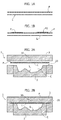
figures 1A, 1B are exploded diagrammatic views of different configurations of a hybrid panel which are provided for carrying out the method of the invention, -
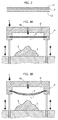
figures 2A-2F show different steps of a first embodiment of the method according to the invention, -
figure 3 is a diagrammatic exploded view of a further configuration of a hybrid panel provided for carrying out the method of the invention, -
figures 4A-4C show the subsequent steps of a further embodiment of the method according to the invention, and -
figures 5A-5F show the various steps of a further embodiment of the method according to the invention. - With reference to
figure 1A , the method according to the invention may be applied for example to a blank constituted by a sheet element of light alloy L, such as magnesium alloy or aluminium alloy, and a sheet of plastic material P. - As shown in
figure 1 , both elements L, P are substantially planar. - They are coupled with each other so as to be in contact substantially along their entire extension, in a loose condition, i.e. without any preliminary mutual connection. In the preferred embodiment, the plastic material constituting the sheet P is a composite material comprising a matrix of plastic resin, such as polypropylene or polyamide and reinforcing fibres, such as carbon fibres or glass fibres. The blank constituted by the two elements P,L in contact with each other is preliminarily arranged within a
mould structure 1 comprising afirst mould element 2 having anupper surface 20 in which a mould cavity C is formed defining a forming surface S. The two elements P,L in contact with each other are applied above theupper surface 20 of themould element 2 and pressed thereon at the peripheral portions by means of a closing element 3 (figure 2B ). Thefirst mould element 2 and theclosing element 3 are pressed against each other with a predetermined and controlled force. - The entire process is carried out with simultaneous application of heat, such as by using heated mould elements and if required by providing also a preliminary step of heating the elements P,L before they are introduced within
structure 1. - In the annexed drawings, the details of construction of the forming elements and the devices provided for moving these elements between the opened condition shown in
figure 2A and the closed condition shown infigure 2B , as well as the devices which are for applying the required pressure in order to press theclosing element 3 above themould element 2, are not illustrated, since they can be made in any known way and since they do not fall, taken alone, within the scope of the present invention. The deletion of these details from the drawings also renders the latter simpler and easier to understand. - With reference also to
figures 2A-2F , the coveringelement 3 has at least onepassage 30 which is used for supplying gas under pressure against the blank constituted by the two elements P,L in contact with each other. The guess may be nitrogen or argon. The supply pressure may vary between 10 bar and 200 bar, depending upon the applications. The temperature at which the method described herein is carried out may vary between 150°C and 350°C, preferably between 150°C and 200 °C, also in this case depending upon the applications and the characteristics of the materials constituting the elements P,L. - The gas under pressure supplied through
passage 30 causes a progressive deformation of the hybrid panel constituted by the elements P,L of plastic material and light alloy until it is caused to adhere against the forming surface S so as to assume the corresponding shape. The duration of the process may arrive to be in the order of 2-3 minutes. - In case the plastic material is a composite plastic material reinforced with fibres, curing of the resin matrix is obtained during the forming process.
- Once forming is obtained, the
closing element 3 is raised for enabling the hybrid panel Q to be removed from the mould structure. An important feature of the present invention lies in that preliminarily to the forming step, the surface of the sheet element of light alloy L which is to come in contact with the sheet of plastic material P is subjected to a roughening process (such as by sand-blasting, by chemical etching or by laser processing) in order to enable adhesion of the plastic material to the sheet metal following softening of the plastic material which takes place during the hot pressing, for which the plastic material fills the gaps between the asperities of the surface of the element of light alloy. - In the example of
figures 2A ,2F a single sheet element L and a single sheet of plastic material P are provided, arranged with the sheet metal element L facing towards the forming surface S, so that on the opposite side the sheet of plastic material may be provided with additional layers P1, P2 localized at portions of the panel which require to be reinforced, according to what is illustrated infigures 1B . - The same process shown in
figures 2A-2F can be carried out of course by inverting the position of the two elements P, L, i.e. by arranging the element of plastic material P in direct contact with the forming surface. Yet according to a further alternative, it is possible to provide a blank of the type shown infigure 3 , constituted by a sheet of plastic material P, interposed between two sheet elements of light alloy L1, L2. -
Figures 4A-4C show an alternative embodiment in which the forming surface S is a projecting surface defined by afirst mould element 2. - In this case the hybrid panel Q constituted for example as shown in
figure 1A or 1B or3 is clamped between peripheral portions of a verticallymovable frame 4 which is lowered with a force F above thefirst mould element 2. Betweenframe 4 and the hybrid panel Q a cavity D is defined which is supplied with gas under pressure through apassage 40 formed through theframe 4. Once the hybrid panel Q has been clamped withinframe 4, gas under pressure is supplied within chamber D (figure 4B ) whileframe 4 is lowered above themould element 2 with the projecting forming surface S (figure 4C ) until the hybrid panel Q is pressed in contact against the entire projecting surface S, so as to be formed in the desired manner. -
Figures 5A-5F show a method very similar to that offigures 2A-2F with the only difference that in this case the hybrid panel is pressed against the forming surface S of thefirst mould element 2 not by gas under pressure, but rather by means of asecond mould element 5 having alower surface 50 with a similar shape to that of the forming surface S of thefirst mould element 2. - As readily apparent from the foregoing description, the method according to the invention enables hybrid structures having multi-layered walls of light alloy and plastic material to be obtained in a simple and efficient manner.
- The method may be used advantageously for example for providing components of motor-vehicle structures, such as portions of motor-vehicle floor panel.
- Naturally, while the principle of the invention remains the same, the details of construction and the embodiments may widely vary with respect to what has been described and illustrated purely by way of example, without departing from the scope of the present invention.
Claims (12)
- Method for obtaining a component of a motor-vehicle structure by means of a hot pressing operations on at least one sheet element of light alloy (L), such as aluminium alloy or magnesium alloy, said method comprising the steps of:- providing at least one sheet element of light alloy (L) adjacent to a mould element (2) having a forming surface (S),- hot forming said at least one sheet element of light alloy (L) by pressing it against said forming surface (S) of said mould element (2) with a predetermined controlled pressure and by simultaneously applying heat, until the sheet element of light alloy (L) assumes a configuration corresponding to that of said forming surface (S),said method being characterized in that:- in addition to said at least one sheet element of light alloy (L) at least one sheet of plastic material (P) is provided in contact with the sheet element of light alloy (L) substantially along the entire extension thereof, so as to define a hybrid panel (Q) having at least one layer of light alloy sheet (L) and one layer of plastic material (P),- said hot forming step being applied to said hybrid panel (Q) in its entirety, so that following said operation the hybrid panel (Q) assumes a configuration corresponding to that of the forming surface (S), whereas said at least one sheet element of light alloy (L) and said at least one sheet of plastic material (P) constituting the hybrid panel (Q) are caused to adhere to each other following softening by heat of the sheet of plastic material (P),- preliminarily to the hot forming step of the hybrid panel (Q), the surface of said sheet element of light alloy which is to come in contact with the sheet of plastic material is subjected to a roughening treatment, so as to define surface asperities between which the plastic material of the sheet of plastic material (P) is inserted when it is softened by heat.
- Method according to claim 1, characterized in that said hot forming step is made by pressing the hybrid panel (Q) against said forming surface (S) by a gas under pressure.
- Method according to claim 1, characterized in that said hot forming step of the hybrid panel (Q) is made by pressing the hybrid panel (Q) against said forming surface (S) of the first mould element (2) by means of a second mould element (5).
- Method according to claim 3, characterized in that said first mould element (2) comprises a cavity (C) defining said forming surface (S), in that said hybrid panel (Q) is applied above said first mould element (2) so as to be in contact with lateral portions of said first mould element (2) so as to overlie said cavity (C), in that in this condition a closing element (3) is applied above said hybrid panel (Q), so as to press said peripheral portions of the hybrid panel (Q) against said lateral portions of the first mould element (2) and in that said closing element (3) has a passage (30) through which fluid under pressure is supplied, so as to push the hybrid panel (Q) against the surface (S) of said cavity (C).
- Method according to claim 3, characterized in that said first mould element (2) defines a projecting forming surface (S) and in that the hybrid panel (Q) is clamped along its periphery within a vertically movable frame (T) which is lowered above said projecting surface (S) and in that between the vertically movable frame (T) and the hybrid panel (Q) clamped thereto a chamber (D) is defined in which fluid under pressure is supplied for pressing the hybrid panel (Q) against said forming surface (S).
- Method according to claim 1, characterized in that the hybrid panel (Q) comprises a single sheet element of light alloy (L) and a single sheet of plastic material (P).
- Method according to claim 1, characterized in that the hybrid panel (Q) comprises a sheet of plastic material (P) interposed between two sheet elements of light alloy (L1, L2).
- Method according to claim 1, characterized in that plastic material is a composite material having a matrix of plastic resin, such as polypropylene or polyamide and reinforcing fibres, such as carbon fibres or glass fibres.
- Method according to claim 1, characterized in that the hot forming operation is carried out at a temperature between 150°C and 350° C, preferably between 150° C and 250 C.
- Method according to claim 3, characterized in that the gas under pressure is supplied at a pressure between 10 bars and 200 bars through a time not greater than two minutes.
- Method according to claim 1, characterized in that said at least one sheet element of light alloy has a thickness between 0.1 mm and 2 mm.
- Method according to claim 1, characterized in that a single sheet metal element (L) and a single sheet of plastic material (P) are provided, arranged with the sheet metal element (L) facing towards the forming surface (S), so that on the opposite side the sheet of plastic material can be provided with additional layers (P1, P2) localized at portions of the panel which require to be strengthened.
Priority Applications (2)
| Application Number | Priority Date | Filing Date | Title |
|---|---|---|---|
| EP16178085.3A EP3266609B1 (en) | 2016-07-06 | 2016-07-06 | Method for producing components for motor-vehicle structures, having a hybrid structure made of light alloy and plastic material |
| US15/635,257 US10821495B2 (en) | 2016-07-06 | 2017-06-28 | Method for producing components for motor-vehicle structures, having a hybrid structure made of light alloy and plastic material |
Applications Claiming Priority (1)
| Application Number | Priority Date | Filing Date | Title |
|---|---|---|---|
| EP16178085.3A EP3266609B1 (en) | 2016-07-06 | 2016-07-06 | Method for producing components for motor-vehicle structures, having a hybrid structure made of light alloy and plastic material |
Publications (2)
| Publication Number | Publication Date |
|---|---|
| EP3266609A1 true EP3266609A1 (en) | 2018-01-10 |
| EP3266609B1 EP3266609B1 (en) | 2019-09-25 |
Family
ID=56799203
Family Applications (1)
| Application Number | Title | Priority Date | Filing Date |
|---|---|---|---|
| EP16178085.3A Active EP3266609B1 (en) | 2016-07-06 | 2016-07-06 | Method for producing components for motor-vehicle structures, having a hybrid structure made of light alloy and plastic material |
Country Status (2)
| Country | Link |
|---|---|
| US (1) | US10821495B2 (en) |
| EP (1) | EP3266609B1 (en) |
Cited By (5)
| Publication number | Priority date | Publication date | Assignee | Title |
|---|---|---|---|---|
| CN108296351A (en) * | 2018-01-30 | 2018-07-20 | 张培栋 | A kind of method for the high-pressure molding that prestores and the high-pressure molding mould structure that prestores |
| CN110788190A (en) * | 2019-10-25 | 2020-02-14 | 华中科技大学 | Method for hot stamping part by adopting aluminum alloy plate and carbon fiber composite material |
| CN111941093A (en) * | 2020-08-04 | 2020-11-17 | 韦民华 | A kind of blow molding stainless steel chair production process |
| CN113714375A (en) * | 2021-09-10 | 2021-11-30 | 北京航空航天大学 | Follow-up forming method for complex thin-wall part |
| CN113751569A (en) * | 2021-08-20 | 2021-12-07 | 西安飞机工业(集团)有限责任公司 | Airplane hatch cover skin liquid filling forming method |
Families Citing this family (2)
| Publication number | Priority date | Publication date | Assignee | Title |
|---|---|---|---|---|
| CN111727149B (en) * | 2018-10-12 | 2022-05-17 | 日本制铁株式会社 | Skeleton Parts |
| US20250249496A1 (en) * | 2024-02-01 | 2025-08-07 | The Boeing Company | Method of mitigating wrinkles during the manufacture of super-plastically formed parts |
Citations (9)
| Publication number | Priority date | Publication date | Assignee | Title |
|---|---|---|---|---|
| US3352742A (en) * | 1963-03-06 | 1967-11-14 | Nat Lead Co | Laminates |
| US3455775A (en) * | 1966-05-26 | 1969-07-15 | Bell Telephone Labor Inc | Metal-plastic laminate and method for the preparation thereof |
| EP0007639A1 (en) * | 1978-07-31 | 1980-02-06 | Bethlehem Steel Corporation | New metal plastic laminates from polyolefin compositions having high impact resistance and high temperature flow resistance |
| US4390489A (en) * | 1977-12-19 | 1983-06-28 | Allied Corporation | Method of shaping thermoplastic compositions on aluminum foil support |
| US4657717A (en) * | 1984-03-16 | 1987-04-14 | Alcan International Limited | Forming fibre-plastics composites |
| EP0598428A1 (en) * | 1992-11-11 | 1994-05-25 | Hoogovens Hylite BV | Metal-polypropylene-metal laminate and method of making a shaped sheet article of such a laminate |
| EP0692371A1 (en) * | 1994-07-13 | 1996-01-17 | Alusuisse-Lonza Services AG | Deformable composite panel |
| EP2647486A1 (en) * | 2010-12-02 | 2013-10-09 | Toray Industries, Inc. | Method for producing metal composite, and chassis for electronic equipment |
| DE102013110282A1 (en) * | 2013-09-18 | 2015-03-19 | Thyssenkrupp Steel Europe Ag | Metal-plastic sandwich sheet and process for its production |
Family Cites Families (5)
| Publication number | Priority date | Publication date | Assignee | Title |
|---|---|---|---|---|
| US3838506A (en) * | 1973-04-09 | 1974-10-01 | Ibm | Aluminum surface and treatment thereof to enhance adhesion in printed circuit laminates |
| US5410132A (en) * | 1991-10-15 | 1995-04-25 | The Boeing Company | Superplastic forming using induction heating |
| TW496823B (en) * | 1998-12-23 | 2002-08-01 | Dung-Han Juang | Process for manufacturing an electromagnetic interference shielding superplastic alloy foil cladded plastic outer shell product |
| EP2907597B1 (en) * | 2014-02-17 | 2016-02-17 | C.R.F. Società Consortile per Azioni | Method for forming a sheet made of an aluminium alloy by high pressure into a component of complex shape, particularly a motor-vehicle component |
| US9511404B1 (en) * | 2015-07-01 | 2016-12-06 | Po Ming Huang | Sheet molding device |
-
2016
- 2016-07-06 EP EP16178085.3A patent/EP3266609B1/en active Active
-
2017
- 2017-06-28 US US15/635,257 patent/US10821495B2/en active Active
Patent Citations (9)
| Publication number | Priority date | Publication date | Assignee | Title |
|---|---|---|---|---|
| US3352742A (en) * | 1963-03-06 | 1967-11-14 | Nat Lead Co | Laminates |
| US3455775A (en) * | 1966-05-26 | 1969-07-15 | Bell Telephone Labor Inc | Metal-plastic laminate and method for the preparation thereof |
| US4390489A (en) * | 1977-12-19 | 1983-06-28 | Allied Corporation | Method of shaping thermoplastic compositions on aluminum foil support |
| EP0007639A1 (en) * | 1978-07-31 | 1980-02-06 | Bethlehem Steel Corporation | New metal plastic laminates from polyolefin compositions having high impact resistance and high temperature flow resistance |
| US4657717A (en) * | 1984-03-16 | 1987-04-14 | Alcan International Limited | Forming fibre-plastics composites |
| EP0598428A1 (en) * | 1992-11-11 | 1994-05-25 | Hoogovens Hylite BV | Metal-polypropylene-metal laminate and method of making a shaped sheet article of such a laminate |
| EP0692371A1 (en) * | 1994-07-13 | 1996-01-17 | Alusuisse-Lonza Services AG | Deformable composite panel |
| EP2647486A1 (en) * | 2010-12-02 | 2013-10-09 | Toray Industries, Inc. | Method for producing metal composite, and chassis for electronic equipment |
| DE102013110282A1 (en) * | 2013-09-18 | 2015-03-19 | Thyssenkrupp Steel Europe Ag | Metal-plastic sandwich sheet and process for its production |
Cited By (6)
| Publication number | Priority date | Publication date | Assignee | Title |
|---|---|---|---|---|
| CN108296351A (en) * | 2018-01-30 | 2018-07-20 | 张培栋 | A kind of method for the high-pressure molding that prestores and the high-pressure molding mould structure that prestores |
| CN108296351B (en) * | 2018-01-30 | 2019-08-30 | 张培栋 | A kind of method prestoring high-pressure molding and prestore high-pressure molding mould structure |
| CN110788190A (en) * | 2019-10-25 | 2020-02-14 | 华中科技大学 | Method for hot stamping part by adopting aluminum alloy plate and carbon fiber composite material |
| CN111941093A (en) * | 2020-08-04 | 2020-11-17 | 韦民华 | A kind of blow molding stainless steel chair production process |
| CN113751569A (en) * | 2021-08-20 | 2021-12-07 | 西安飞机工业(集团)有限责任公司 | Airplane hatch cover skin liquid filling forming method |
| CN113714375A (en) * | 2021-09-10 | 2021-11-30 | 北京航空航天大学 | Follow-up forming method for complex thin-wall part |
Also Published As
| Publication number | Publication date |
|---|---|
| US10821495B2 (en) | 2020-11-03 |
| EP3266609B1 (en) | 2019-09-25 |
| US20180009019A1 (en) | 2018-01-11 |
Similar Documents
| Publication | Publication Date | Title |
|---|---|---|
| US10821495B2 (en) | Method for producing components for motor-vehicle structures, having a hybrid structure made of light alloy and plastic material | |
| US20170072602A1 (en) | System and method for manufacturing an article | |
| KR102773794B1 (en) | Method for manufacturing a pressurized two-dimensional or three-dimensional shaped sandwich composite part and such composite part | |
| US12083750B2 (en) | Method and device for producing a component from a fiber composite material | |
| JP6689377B2 (en) | Method for manufacturing parts made of fiber composite material | |
| US6797087B2 (en) | Composite molded article, steering wheel and production method therefor | |
| JP6005086B2 (en) | Method for manufacturing composite structure | |
| US20140225296A1 (en) | Method of making a sandwich-type, compression-molded, composite component having improved surface appearance | |
| JP2019035505A (en) | Design features of dissimilar material-reinforced blanks and extrusions for forming | |
| JP2010500932A (en) | Manufacturing method of workpiece made of fiber composite material, and fiber composite part in the shape of a deformed material having a cross-sectional contour that varies over the entire length | |
| JP2018531168A6 (en) | Method for manufacturing a component made of fiber composite material | |
| KR101891824B1 (en) | Method of manufacturing hybrid vehicle body part with different material | |
| US7771557B2 (en) | Method for joining a stringer to a structural component of an aircraft or spacecraft | |
| KR20170075362A (en) | Mold device for forming vehicle body part and method of manufacturing vehicle body part using the mold device | |
| JP2019119147A (en) | Manufacturing method of resin-reinforced metallic part | |
| EP3650207B1 (en) | Method for obtaining a joint between elements of different materials | |
| US20020170662A1 (en) | Twin-wall composite sheet | |
| US20180304542A1 (en) | Composite Component for a Vehicle, in Particular a Motor Vehicle, and Method for the Production of a Composite Component | |
| US9662811B2 (en) | Self-fixturing metallic composite laminate | |
| JP6895675B2 (en) | Joining structure of fiber reinforced plastic material and metal material and its joining method | |
| US20130266783A1 (en) | Method for producing moldings having different surface materials | |
| JP6884168B2 (en) | Manufacturing method of press-molded products | |
| KR20130078524A (en) | Method for making composite hollow structures and metallic mould the same | |
| US10475432B2 (en) | Process for manufacturing an acoustic panel reinforced by at least one thermoplastic composite layer | |
| TW201726407A (en) | Composite steel |
Legal Events
| Date | Code | Title | Description |
|---|---|---|---|
| PUAI | Public reference made under article 153(3) epc to a published international application that has entered the european phase |
Free format text: ORIGINAL CODE: 0009012 |
|
| STAA | Information on the status of an ep patent application or granted ep patent |
Free format text: STATUS: REQUEST FOR EXAMINATION WAS MADE |
|
| 17P | Request for examination filed |
Effective date: 20170621 |
|
| AK | Designated contracting states |
Kind code of ref document: A1 Designated state(s): AL AT BE BG CH CY CZ DE DK EE ES FI FR GB GR HR HU IE IS IT LI LT LU LV MC MK MT NL NO PL PT RO RS SE SI SK SM TR |
|
| AX | Request for extension of the european patent |
Extension state: BA ME |
|
| STAA | Information on the status of an ep patent application or granted ep patent |
Free format text: STATUS: EXAMINATION IS IN PROGRESS |
|
| 17Q | First examination report despatched |
Effective date: 20180614 |
|
| GRAP | Despatch of communication of intention to grant a patent |
Free format text: ORIGINAL CODE: EPIDOSNIGR1 |
|
| STAA | Information on the status of an ep patent application or granted ep patent |
Free format text: STATUS: GRANT OF PATENT IS INTENDED |
|
| INTG | Intention to grant announced |
Effective date: 20190515 |
|
| GRAS | Grant fee paid |
Free format text: ORIGINAL CODE: EPIDOSNIGR3 |
|
| GRAA | (expected) grant |
Free format text: ORIGINAL CODE: 0009210 |
|
| STAA | Information on the status of an ep patent application or granted ep patent |
Free format text: STATUS: THE PATENT HAS BEEN GRANTED |
|
| AK | Designated contracting states |
Kind code of ref document: B1 Designated state(s): AL AT BE BG CH CY CZ DE DK EE ES FI FR GB GR HR HU IE IS IT LI LT LU LV MC MK MT NL NO PL PT RO RS SE SI SK SM TR |
|
| REG | Reference to a national code |
Ref country code: GB Ref legal event code: FG4D |
|
| REG | Reference to a national code |
Ref country code: CH Ref legal event code: EP |
|
| REG | Reference to a national code |
Ref country code: AT Ref legal event code: REF Ref document number: 1183423 Country of ref document: AT Kind code of ref document: T Effective date: 20191015 |
|
| REG | Reference to a national code |
Ref country code: IE Ref legal event code: FG4D |
|
| REG | Reference to a national code |
Ref country code: DE Ref legal event code: R096 Ref document number: 602016021124 Country of ref document: DE |
|
| REG | Reference to a national code |
Ref country code: NL Ref legal event code: MP Effective date: 20190925 |
|
| PG25 | Lapsed in a contracting state [announced via postgrant information from national office to epo] |
Ref country code: SE Free format text: LAPSE BECAUSE OF FAILURE TO SUBMIT A TRANSLATION OF THE DESCRIPTION OR TO PAY THE FEE WITHIN THE PRESCRIBED TIME-LIMIT Effective date: 20190925 Ref country code: BG Free format text: LAPSE BECAUSE OF FAILURE TO SUBMIT A TRANSLATION OF THE DESCRIPTION OR TO PAY THE FEE WITHIN THE PRESCRIBED TIME-LIMIT Effective date: 20191225 Ref country code: NO Free format text: LAPSE BECAUSE OF FAILURE TO SUBMIT A TRANSLATION OF THE DESCRIPTION OR TO PAY THE FEE WITHIN THE PRESCRIBED TIME-LIMIT Effective date: 20191225 Ref country code: HR Free format text: LAPSE BECAUSE OF FAILURE TO SUBMIT A TRANSLATION OF THE DESCRIPTION OR TO PAY THE FEE WITHIN THE PRESCRIBED TIME-LIMIT Effective date: 20190925 Ref country code: FI Free format text: LAPSE BECAUSE OF FAILURE TO SUBMIT A TRANSLATION OF THE DESCRIPTION OR TO PAY THE FEE WITHIN THE PRESCRIBED TIME-LIMIT Effective date: 20190925 Ref country code: LT Free format text: LAPSE BECAUSE OF FAILURE TO SUBMIT A TRANSLATION OF THE DESCRIPTION OR TO PAY THE FEE WITHIN THE PRESCRIBED TIME-LIMIT Effective date: 20190925 |
|
| REG | Reference to a national code |
Ref country code: LT Ref legal event code: MG4D |
|
| PG25 | Lapsed in a contracting state [announced via postgrant information from national office to epo] |
Ref country code: GR Free format text: LAPSE BECAUSE OF FAILURE TO SUBMIT A TRANSLATION OF THE DESCRIPTION OR TO PAY THE FEE WITHIN THE PRESCRIBED TIME-LIMIT Effective date: 20191226 Ref country code: RS Free format text: LAPSE BECAUSE OF FAILURE TO SUBMIT A TRANSLATION OF THE DESCRIPTION OR TO PAY THE FEE WITHIN THE PRESCRIBED TIME-LIMIT Effective date: 20190925 Ref country code: LV Free format text: LAPSE BECAUSE OF FAILURE TO SUBMIT A TRANSLATION OF THE DESCRIPTION OR TO PAY THE FEE WITHIN THE PRESCRIBED TIME-LIMIT Effective date: 20190925 |
|
| REG | Reference to a national code |
Ref country code: AT Ref legal event code: MK05 Ref document number: 1183423 Country of ref document: AT Kind code of ref document: T Effective date: 20190925 |
|
| PG25 | Lapsed in a contracting state [announced via postgrant information from national office to epo] |
Ref country code: AL Free format text: LAPSE BECAUSE OF FAILURE TO SUBMIT A TRANSLATION OF THE DESCRIPTION OR TO PAY THE FEE WITHIN THE PRESCRIBED TIME-LIMIT Effective date: 20190925 Ref country code: ES Free format text: LAPSE BECAUSE OF FAILURE TO SUBMIT A TRANSLATION OF THE DESCRIPTION OR TO PAY THE FEE WITHIN THE PRESCRIBED TIME-LIMIT Effective date: 20190925 Ref country code: PT Free format text: LAPSE BECAUSE OF FAILURE TO SUBMIT A TRANSLATION OF THE DESCRIPTION OR TO PAY THE FEE WITHIN THE PRESCRIBED TIME-LIMIT Effective date: 20200127 Ref country code: PL Free format text: LAPSE BECAUSE OF FAILURE TO SUBMIT A TRANSLATION OF THE DESCRIPTION OR TO PAY THE FEE WITHIN THE PRESCRIBED TIME-LIMIT Effective date: 20190925 Ref country code: AT Free format text: LAPSE BECAUSE OF FAILURE TO SUBMIT A TRANSLATION OF THE DESCRIPTION OR TO PAY THE FEE WITHIN THE PRESCRIBED TIME-LIMIT Effective date: 20190925 Ref country code: NL Free format text: LAPSE BECAUSE OF FAILURE TO SUBMIT A TRANSLATION OF THE DESCRIPTION OR TO PAY THE FEE WITHIN THE PRESCRIBED TIME-LIMIT Effective date: 20190925 Ref country code: RO Free format text: LAPSE BECAUSE OF FAILURE TO SUBMIT A TRANSLATION OF THE DESCRIPTION OR TO PAY THE FEE WITHIN THE PRESCRIBED TIME-LIMIT Effective date: 20190925 Ref country code: EE Free format text: LAPSE BECAUSE OF FAILURE TO SUBMIT A TRANSLATION OF THE DESCRIPTION OR TO PAY THE FEE WITHIN THE PRESCRIBED TIME-LIMIT Effective date: 20190925 |
|
| PG25 | Lapsed in a contracting state [announced via postgrant information from national office to epo] |
Ref country code: SM Free format text: LAPSE BECAUSE OF FAILURE TO SUBMIT A TRANSLATION OF THE DESCRIPTION OR TO PAY THE FEE WITHIN THE PRESCRIBED TIME-LIMIT Effective date: 20190925 Ref country code: CZ Free format text: LAPSE BECAUSE OF FAILURE TO SUBMIT A TRANSLATION OF THE DESCRIPTION OR TO PAY THE FEE WITHIN THE PRESCRIBED TIME-LIMIT Effective date: 20190925 Ref country code: SK Free format text: LAPSE BECAUSE OF FAILURE TO SUBMIT A TRANSLATION OF THE DESCRIPTION OR TO PAY THE FEE WITHIN THE PRESCRIBED TIME-LIMIT Effective date: 20190925 Ref country code: IS Free format text: LAPSE BECAUSE OF FAILURE TO SUBMIT A TRANSLATION OF THE DESCRIPTION OR TO PAY THE FEE WITHIN THE PRESCRIBED TIME-LIMIT Effective date: 20200224 |
|
| REG | Reference to a national code |
Ref country code: DE Ref legal event code: R097 Ref document number: 602016021124 Country of ref document: DE |
|
| PG2D | Information on lapse in contracting state deleted |
Ref country code: IS |
|
| PG25 | Lapsed in a contracting state [announced via postgrant information from national office to epo] |
Ref country code: DK Free format text: LAPSE BECAUSE OF FAILURE TO SUBMIT A TRANSLATION OF THE DESCRIPTION OR TO PAY THE FEE WITHIN THE PRESCRIBED TIME-LIMIT Effective date: 20190925 Ref country code: IS Free format text: LAPSE BECAUSE OF FAILURE TO SUBMIT A TRANSLATION OF THE DESCRIPTION OR TO PAY THE FEE WITHIN THE PRESCRIBED TIME-LIMIT Effective date: 20200126 |
|
| PLBE | No opposition filed within time limit |
Free format text: ORIGINAL CODE: 0009261 |
|
| STAA | Information on the status of an ep patent application or granted ep patent |
Free format text: STATUS: NO OPPOSITION FILED WITHIN TIME LIMIT |
|
| 26N | No opposition filed |
Effective date: 20200626 |
|
| PG25 | Lapsed in a contracting state [announced via postgrant information from national office to epo] |
Ref country code: SI Free format text: LAPSE BECAUSE OF FAILURE TO SUBMIT A TRANSLATION OF THE DESCRIPTION OR TO PAY THE FEE WITHIN THE PRESCRIBED TIME-LIMIT Effective date: 20190925 |
|
| PG25 | Lapsed in a contracting state [announced via postgrant information from national office to epo] |
Ref country code: MC Free format text: LAPSE BECAUSE OF FAILURE TO SUBMIT A TRANSLATION OF THE DESCRIPTION OR TO PAY THE FEE WITHIN THE PRESCRIBED TIME-LIMIT Effective date: 20190925 |
|
| REG | Reference to a national code |
Ref country code: CH Ref legal event code: PL |
|
| GBPC | Gb: european patent ceased through non-payment of renewal fee |
Effective date: 20200706 |
|
| REG | Reference to a national code |
Ref country code: BE Ref legal event code: MM Effective date: 20200731 |
|
| PG25 | Lapsed in a contracting state [announced via postgrant information from national office to epo] |
Ref country code: CH Free format text: LAPSE BECAUSE OF NON-PAYMENT OF DUE FEES Effective date: 20200731 Ref country code: LU Free format text: LAPSE BECAUSE OF NON-PAYMENT OF DUE FEES Effective date: 20200706 Ref country code: LI Free format text: LAPSE BECAUSE OF NON-PAYMENT OF DUE FEES Effective date: 20200731 Ref country code: IE Free format text: LAPSE BECAUSE OF NON-PAYMENT OF DUE FEES Effective date: 20200706 Ref country code: GB Free format text: LAPSE BECAUSE OF NON-PAYMENT OF DUE FEES Effective date: 20200706 |
|
| PG25 | Lapsed in a contracting state [announced via postgrant information from national office to epo] |
Ref country code: BE Free format text: LAPSE BECAUSE OF NON-PAYMENT OF DUE FEES Effective date: 20200731 |
|
| PG25 | Lapsed in a contracting state [announced via postgrant information from national office to epo] |
Ref country code: TR Free format text: LAPSE BECAUSE OF FAILURE TO SUBMIT A TRANSLATION OF THE DESCRIPTION OR TO PAY THE FEE WITHIN THE PRESCRIBED TIME-LIMIT Effective date: 20190925 Ref country code: MT Free format text: LAPSE BECAUSE OF FAILURE TO SUBMIT A TRANSLATION OF THE DESCRIPTION OR TO PAY THE FEE WITHIN THE PRESCRIBED TIME-LIMIT Effective date: 20190925 Ref country code: CY Free format text: LAPSE BECAUSE OF FAILURE TO SUBMIT A TRANSLATION OF THE DESCRIPTION OR TO PAY THE FEE WITHIN THE PRESCRIBED TIME-LIMIT Effective date: 20190925 |
|
| PG25 | Lapsed in a contracting state [announced via postgrant information from national office to epo] |
Ref country code: MK Free format text: LAPSE BECAUSE OF FAILURE TO SUBMIT A TRANSLATION OF THE DESCRIPTION OR TO PAY THE FEE WITHIN THE PRESCRIBED TIME-LIMIT Effective date: 20190925 |
|
| PGFP | Annual fee paid to national office [announced via postgrant information from national office to epo] |
Ref country code: FR Payment date: 20250620 Year of fee payment: 10 |
|
| PGFP | Annual fee paid to national office [announced via postgrant information from national office to epo] |
Ref country code: DE Payment date: 20250620 Year of fee payment: 10 |
|
| PGFP | Annual fee paid to national office [announced via postgrant information from national office to epo] |
Ref country code: IT Payment date: 20250619 Year of fee payment: 10 |