EP3266018B1 - Display apparatus - Google Patents
Display apparatus Download PDFInfo
- Publication number
- EP3266018B1 EP3266018B1 EP16708200.7A EP16708200A EP3266018B1 EP 3266018 B1 EP3266018 B1 EP 3266018B1 EP 16708200 A EP16708200 A EP 16708200A EP 3266018 B1 EP3266018 B1 EP 3266018B1
- Authority
- EP
- European Patent Office
- Prior art keywords
- display
- projection
- engageable
- flexible
- display member
- Prior art date
- Legal status (The legal status is an assumption and is not a legal conclusion. Google has not performed a legal analysis and makes no representation as to the accuracy of the status listed.)
- Active
Links
- 239000000463 material Substances 0.000 claims description 6
- 230000006835 compression Effects 0.000 claims description 5
- 238000007906 compression Methods 0.000 claims description 5
- 230000001419 dependent effect Effects 0.000 claims 1
- 230000000712 assembly Effects 0.000 description 3
- 238000000429 assembly Methods 0.000 description 3
- 239000003351 stiffener Substances 0.000 description 2
- 238000010276 construction Methods 0.000 description 1
- 229920002457 flexible plastic Polymers 0.000 description 1
- 238000012986 modification Methods 0.000 description 1
- 230000004048 modification Effects 0.000 description 1
- 229920003023 plastic Polymers 0.000 description 1
- 239000004033 plastic Substances 0.000 description 1
Images


Classifications
-
- G—PHYSICS
- G09—EDUCATION; CRYPTOGRAPHY; DISPLAY; ADVERTISING; SEALS
- G09F—DISPLAYING; ADVERTISING; SIGNS; LABELS OR NAME-PLATES; SEALS
- G09F15/00—Boards, hoardings, pillars, or like structures for notices, placards, posters, or the like
- G09F15/0006—Boards, hoardings, pillars, or like structures for notices, placards, posters, or the like planar structures comprising one or more panels
- G09F15/0025—Boards, hoardings, pillars, or like structures for notices, placards, posters, or the like planar structures comprising one or more panels display surface tensioning means
-
- G—PHYSICS
- G09—EDUCATION; CRYPTOGRAPHY; DISPLAY; ADVERTISING; SEALS
- G09F—DISPLAYING; ADVERTISING; SIGNS; LABELS OR NAME-PLATES; SEALS
- G09F15/00—Boards, hoardings, pillars, or like structures for notices, placards, posters, or the like
- G09F15/0006—Boards, hoardings, pillars, or like structures for notices, placards, posters, or the like planar structures comprising one or more panels
- G09F15/0018—Boards, hoardings, pillars, or like structures for notices, placards, posters, or the like planar structures comprising one or more panels panel clamping or fastening means
-
- G—PHYSICS
- G09—EDUCATION; CRYPTOGRAPHY; DISPLAY; ADVERTISING; SEALS
- G09F—DISPLAYING; ADVERTISING; SIGNS; LABELS OR NAME-PLATES; SEALS
- G09F15/00—Boards, hoardings, pillars, or like structures for notices, placards, posters, or the like
- G09F15/0006—Boards, hoardings, pillars, or like structures for notices, placards, posters, or the like planar structures comprising one or more panels
- G09F15/0056—Boards, hoardings, pillars, or like structures for notices, placards, posters, or the like planar structures comprising one or more panels portable display standards
- G09F15/0062—Boards, hoardings, pillars, or like structures for notices, placards, posters, or the like planar structures comprising one or more panels portable display standards collapsible
-
- G—PHYSICS
- G09—EDUCATION; CRYPTOGRAPHY; DISPLAY; ADVERTISING; SEALS
- G09F—DISPLAYING; ADVERTISING; SIGNS; LABELS OR NAME-PLATES; SEALS
- G09F15/00—Boards, hoardings, pillars, or like structures for notices, placards, posters, or the like
- G09F15/0068—Modular articulated structures, e.g. stands, and articulation means therefor
Definitions
- This invention concerns display apparatus.
- Display apparatus is widely used at exhibitions and elsewhere to for instance display details of a company, their products and/or services. It is desirable if such apparatus can readily be erected and also taken down.
- a number of display apparatus use sheets of flexible material, and it is a requirement that these sheets are supported so as to remain as taut as possible so as to provide a pleasing appearance and a clear display.
- a display apparatus comprising a flexible display member in the form of a sheet of material, and a support arrangement, the support arrangement including an elongate support member locatable behind the display member to support same, the support member having a main section with a lower part which is engageable with a lower end of the display member and an upper section which is engageable with an upper end of the display member, the main and upper sections being resiliently urged apart so as to apply tension to the display member when engaged therewith, an upper transverse member is provided connected to the upper section of the support member, opposite ends of the upper transverse member are engageable respectively by connection arrangements with top corners of the display member, characterised in that each connection arrangement comprises a projection on a one of the display member or upper transverse member, which projection is selectively locatable in a corresponding recess provided by the connection arrangement in the other of the display member or upper transverse member, with the recess and/or projection being profiled such that as the upper transverse member is moved upwardly
- the apparatus may include a lower transverse member at a lower end of the main section of the elongate support member, which lower transverse member is engageable with lower corners of the display member.
- Respective connection arrangements may be provided for engaging together the lower transverse member and lower corners of the display member.
- each connection arrangement may include a profiled edge engageable with an edge of the respective recess such that as for instance when the upper transverse member is moved upwardly, this urges the upper corners of the flexible display member outwardly.
- the profiled edge of the projection may be inclined relative to a vertical alignment, and at upper ends of the display member may be inclined upwardly inwards. At lower ends of the display member the projection profiled edge may be inclined downwardly inwards.
- a profiled edge may be provided on the recesses with which profiled edge the respective projection profiled edge is engageable.
- Cooperable magnets may be provided respectively on the projections and recesses to facilitate correct location of a projection in a corresponding recess.
- the projections may be provided on the transverse member or members, with the recesses provided on corners of the display member.
- Stiffening strips may be provided at one or both ends of the display member, and the recesses may be mounted at respective ends of the strips.
- a lip may be provided in the recesses such that a part of the respective projections locates behind the lip when engaged with the respective recess, to retain the projection in the recess.
- the profiled edge of the projection and/or recess may be inclined at an angle of between 30 and 60° to the vertical, and may be inclined at an angle of between 40 and 50° to the vertical.
- the apparatus may include a ground engageable base.
- the base may include a foot, which foot may extend forwards and rearwards relative to the elongate support member.
- the base may include ground engageable projections extending from the underside of the lower transverse member.
- the elongate support member may comprise an elongate part providing the main section, and a mounting part providing the upper section, which mounting part is vertically slidably movable along an upper section of the elongate part, and is resiliently upwardly urged.
- a channel may be provided in the elongate support member which slidably locates the mounting part.
- a fixed member may be provided in the channel with the mounting part located in the channel above the fixed member with a resilient member located therebetween.
- the resilient member may be in the form of a compression spring.
- An upper mounting bracket which mounts the upper transverse member may connect to the mounting part, and a part of the mounting part may locate in a channel.
- a lower mounting bracket may be fixedly connected to a lower part of the elongate support member to mount the lower transverse member.
- a display assembly incorporating a plurality of display apparatus according to any of the preceding sixteen paragraphs.
- the assembly may also include one or more additional flexible display members which are extendible between a pair of flexible display members supported by respective support arrangements, but which additional flexible display member is not supported by a respective support arrangement.
- Adjacent flexible display members may be mountable together, and may have cooperable strips extending along their side edges.
- the cooperable strips may include respective magnets.
- a magnetic strip may be provided along each side edge of the flexible display members on the rear side thereof, and a flexible connecting member including an elongate flexible magnet may be locatable behind and overlapping the flexible display members, and magnetically engageable with the respective flexible magnets on the adjacent display members.
- the flexible connecting member may include an upper mounting bracket which is engageable with respective connection arrangements on the upper corners of the flexible display members.
- a mounting bracket may be provided at the lower end of the flexible connecting magnet engageable with respective lower connecting arrangements.
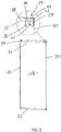
- Each apparatus 10 includes a flexible display member 14 which may be made for instance of a sheet of plastics material and may be decorated or marked with appropriate material on its front face.
- Each apparatus 10 also includes a support arrangement 16.
- Each display member 14 comprises a rectangular sheet 18 which is around two and a half times taller than it is wide.
- a length of magnetic tape 20 is provided on the rear side of the sheet 18 along each side edge.
- a flexible plastics material stiffener strip 22 is provided extending across the top and bottom edges of the sheet 18, again on the rear side thereof.
- a first connection arrangement 24 is provided at each corner of the sheet 18 again on the rear side thereof.
- Each first connection arrangement 24 comprises a rear plate 26 mountable to the respective stiffener strip 22.
- a profiled front plate 28 is provided spaced from the rear plate 26 to define a profiled recess therebetween. The front plate 28 extends for almost the full height of the rear plate 26 adjacent the corner of the sheet 18, but spaced inwardly from each respective corner the front plate has a profiled lip 30.
- the profiled lip 30 provides a recess 32 with an inclined face 34 extending towards the outer edge of the respective sheet 28 for the majority of the height of the rear plate 16, with the inclined face 34 terminating in a generally semi-circular face 36 leading to a downwardly extending lip 38 extending for part of a height of the rear plate 26.
- a further recess 40 is provided between the rear and front plates 26, 28 on the outer edge of the sheet 18, for a purpose hereinafter to be described.
- a first connection arrangement 24 is provided on each corner of the sheet 18, with the inclined face 34 inclined towards the respective side edge of the sheet 18 and also away from the respective top or bottom edge of the sheet 18.
- the configuration of the first connection arrangement 24 on each corner is best shown diagrammatically in Fig. 9 .
- Each support arrangement 16 comprises a foot 42 which extends forwards and rearwards.
- An elongate support member 44 is upstanding from the foot 42.
- the support member 44 has a front facing channel 46.
- a lower transverse member 48 is provided mounted to the support member 44 by a bracket (not shown) engaging in the channel 46.
- Downwardly extending feet 50 are provided on the underside of the lower transverse member 48 towards each end so as to be ground engaging.
- a second connection arrangement 52 is provided on the front side at each end of the lower transverse member 48 and will be hereinafter described.
- An upper transverse member 54 is also provided.
- the upper transverse member 54 is mounted to a profiled bracket 56 of a similar type which mounts the lower transverse member 46 but is not visible in the drawings.
- the mounting bracket 56 has a finger 58 which is slidably located in the channel 46. Located in the channel 46 immediately below the finger 58 is a sliding block 60 with a projection 62 which engages in a recess in the lower end of the finger 58. Below the sliding block 60 a compression spring 64 is located in the channel 46, which spring 64 rests on a fixed block 66 located in the channel 46 a short distance below the top of the elongate support member 44. The compression spring 64 urges the finger 58 and hence bracket 56 upwardly.
- Each second connection arrangement 52 is provided on each end of the lower and upper transverse members 48, 54.
- Each second connection arrangement 52 comprises a rear plate 68 from which a profiled projection 70 extends.
- the projection 70 has a generally rounded triangular profile as can be shown in Fig. 2 and 9 , and the projection locates in the recess 32 provided by the first connection arrangement 24.
- the triangle of the projection has two perpendicular sides interconnected by an inclined side 72, which inclined side faces outwardly and upwards on the upper transverse members 54, and downwardly on the lower transverse member 48.
- a lip 71 is provided on the inclined side 72 of the projection 70, and the lip 71 locates in the recess 32 to retain together the first and second connection arrangements 24, 52.
- a first magnet 73 is provided within the projection 70.
- a second cooperable magnet 75 is provided in the plate 26 at a location to correspond to the magnet 73 when the lip 71 is engaged with the recess 32, to further retain together the first and second connection arrangements 24, 52.
- Each second connection arrangement 52 is configured such that the inclined side 72 engages against the inclined face 34 of the first connection arrangement 24.
- the flexible display member 14 is mounted on the support arrangement 16 by location of the projections 70 on the support arrangement 16, in the respective recesses 32 on the first connection arrangements 24 in each corner of the sheet 18.
- To mount the display member 14 on the support arrangement 16 it would generally be necessary to hold down the upper transverse bar 54 against the force of the compression spring 64.
- Fig. 4 illustrates the forces and tension applied to the flexible display member 14 by the support arrangement 16, once mounted thereto.
- the main force applied is shown by the arrow 74 by virtue of the spring 64 urging the upper transverse member 54 upwardly.
- This provides vertical tension shown by the arrows 76 in the sheet 18.
- a resultant force shown by the arrows 78 is provided in each corner of the sheet 18 in an outwards direction. This then also produces a horizontal tension in the sheet 18 shown by the arrows 80.
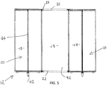
- Fig. 5 and also Figs. 15 - 20 show a display arrangement 12 with two display apparatus 10 with an intermediate flexible display member 82 between the two display apparatus 10, which intermediate display member 82 does not require a respective support arrangement 16. Otherwise the intermediate display member 82 is the same as the display members 14 on either side.
- Figs. 12 - 14 show interconnection of two flexible display members 14, one supported by a support arrangement 16 with the upper transverse member 52, and the other being an intermediate display member 82.
- the magnetic tapes 20 on each sheet 18 are aligned next to each other.
- a connector member 84 is then introduced.
- the connector member 84 has an upper profiled member 86, part of which can slidingly locate respectively in the recesses 40 on each side of the first connection arrangements 24.
- a flexible magnetic tape 88 which can extend on the rear side of the magnetic tapes 20 to interconnect these.
- the magnetic tape 88 is flexible this permits the display assemblies 12 to adopt for instance any of the configurations shown in Figs. 15 - 20 .
- Figs. 15 and 16 show a straight configuration.
- Figs. 17 and 18 show a concave configuration, and as can be seen the intermediate flexible display member 82 can curve appropriately.
- Figs. 19 and 20 show a convex configuration of the display assembly 12.
- a display apparatus and one which permits a wide range of display assemblies to be formed, which provides a number of advantageous features. Whilst the apparatus is of relatively straightforward construction, it can provide an aesthetically pleasing arrangement with a well supported and tensioned flexible display member. This apparatus permits semi-rigid display members to be used which can provide aesthetically pleasing curves, in contrast to many prior arrangements.
- display apparatus and assemblies according to the invention can be used in a wide range of configurations, and with different flexible display members as may be desired. Similar display members can be used whether supported or extending between supported display members. This provides significant flexibility in allowing any required number of display members to be used, and the expense of different types of supported and unsupported display members is avoided. Accordingly different arrangements of display members could be used for different situations so that more display members could be used where a large area is available, but only a reduced number of display members could be used in smaller locations.
- the apparatus can however readily be assembled, and also collapsed.
- the foot 42 and elongate support member 44 can be disengaged.
- the lower and upper transverse members 48, 54 can be disengaged from the respective brackets 56.
- the elongate support member 42 may be formed in three parts 90.
- the flexible display member 14 can be removed from the support arrangement 16 and rolled up or otherwise stored.
- the connector member 84 can also be rolled for storage.
Landscapes
- Physics & Mathematics (AREA)
- General Physics & Mathematics (AREA)
- Engineering & Computer Science (AREA)
- Theoretical Computer Science (AREA)
- Devices For Indicating Variable Information By Combining Individual Elements (AREA)
- Display Racks (AREA)
Description
- This invention concerns display apparatus.
- Display apparatus is widely used at exhibitions and elsewhere to for instance display details of a company, their products and/or services. It is desirable if such apparatus can readily be erected and also taken down. A number of display apparatus use sheets of flexible material, and it is a requirement that these sheets are supported so as to remain as taut as possible so as to provide a pleasing appearance and a clear display.
-
US2009/056184 ,WO2006/086847 andWO2012/115566 each disclose display apparatus comprising a flexible display member. - According to a first aspect of the invention there is provided a display apparatus, the apparatus comprising a flexible display member in the form of a sheet of material, and a support arrangement, the support arrangement including an elongate support member locatable behind the display member to support same, the support member having a main section with a lower part which is engageable with a lower end of the display member and an upper section which is engageable with an upper end of the display member, the main and upper sections being resiliently urged apart so as to apply tension to the display member when engaged therewith, an upper transverse member is provided connected to the upper section of the support member, opposite ends of the upper transverse member are engageable respectively by connection arrangements with top corners of the display member, characterised in that each connection arrangement comprises a projection on a one of the display member or upper transverse member, which projection is selectively locatable in a corresponding recess provided by the connection arrangement in the other of the display member or upper transverse member, with the recess and/or projection being profiled such that as the upper transverse member is moved upwardly this causes the respective top corners of the display member to be urged outwardly thereby applying tension across the top of the display member by virtue of the resilient urging of the upper transverse member, and the profiles of the connection.
- The apparatus may include a lower transverse member at a lower end of the main section of the elongate support member, which lower transverse member is engageable with lower corners of the display member.
- Respective connection arrangements may be provided for engaging together the lower transverse member and lower corners of the display member.
- The projection on each connection arrangement may include a profiled edge engageable with an edge of the respective recess such that as for instance when the upper transverse member is moved upwardly, this urges the upper corners of the flexible display member outwardly.
- The profiled edge of the projection may be inclined relative to a vertical alignment, and at upper ends of the display member may be inclined upwardly inwards. At lower ends of the display member the projection profiled edge may be inclined downwardly inwards.
- A profiled edge may be provided on the recesses with which profiled edge the respective projection profiled edge is engageable.
- Cooperable magnets may be provided respectively on the projections and recesses to facilitate correct location of a projection in a corresponding recess.
- The projections may be provided on the transverse member or members, with the recesses provided on corners of the display member. Stiffening strips may be provided at one or both ends of the display member, and the recesses may be mounted at respective ends of the strips.
- A lip may be provided in the recesses such that a part of the respective projections locates behind the lip when engaged with the respective recess, to retain the projection in the recess.
- The profiled edge of the projection and/or recess may be inclined at an angle of between 30 and 60° to the vertical, and may be inclined at an angle of between 40 and 50° to the vertical.
- The apparatus may include a ground engageable base. The base may include a foot, which foot may extend forwards and rearwards relative to the elongate support member.
- The base may include ground engageable projections extending from the underside of the lower transverse member.
- The elongate support member may comprise an elongate part providing the main section, and a mounting part providing the upper section, which mounting part is vertically slidably movable along an upper section of the elongate part, and is resiliently upwardly urged.
- A channel may be provided in the elongate support member which slidably locates the mounting part. A fixed member may be provided in the channel with the mounting part located in the channel above the fixed member with a resilient member located therebetween. The resilient member may be in the form of a compression spring.
- An upper mounting bracket which mounts the upper transverse member may connect to the mounting part, and a part of the mounting part may locate in a channel.
- A lower mounting bracket may be fixedly connected to a lower part of the elongate support member to mount the lower transverse member.
- According to a second aspect of the invention there is provided a display assembly incorporating a plurality of display apparatus according to any of the preceding sixteen paragraphs.
- The assembly may also include one or more additional flexible display members which are extendible between a pair of flexible display members supported by respective support arrangements, but which additional flexible display member is not supported by a respective support arrangement.
- Adjacent flexible display members may be mountable together, and may have cooperable strips extending along their side edges. The cooperable strips may include respective magnets. A magnetic strip may be provided along each side edge of the flexible display members on the rear side thereof, and a flexible connecting member including an elongate flexible magnet may be locatable behind and overlapping the flexible display members, and magnetically engageable with the respective flexible magnets on the adjacent display members.
- The flexible connecting member may include an upper mounting bracket which is engageable with respective connection arrangements on the upper corners of the flexible display members. A mounting bracket may be provided at the lower end of the flexible connecting magnet engageable with respective lower connecting arrangements.
- Embodiments of the present invention will now be described by way of example only and with reference to the accompanying drawings, in which:-
-
Fig. 1 is a diagrammatic front view of a display apparatus according to the invention; -
Fig. 2 is a diagrammatic front view of part of the display apparatus ofFig. 1 , with an enlarged detailed section; -
Fig. 3 is a diagrammatic rear view with a detailed section of another part of the apparatus ofFig. 1 ; -
Fig. 4 is a diagrammatic rear view of the apparatus ofFig. 1 ; -
Fig. 5 is a diagrammatic rear view of a display assembly according to the invention; -
Fig. 6 is a diagrammatic perspective rear view of the apparatus ofFig. 1 ; -
Fig. 7 is a detailed view of the circled part of the apparatus ofFig.6 ; -
Fig. 8 is a diagrammatic front perspective view of part of the apparatus ofFig. 1 ; -
Fig. 9 is a diagrammatic illustrative rear view showing parts of the apparatus ofFig. 1 ; -
Fig. 10 is a diagrammatic perspective front view of part of the apparatus ofFig. 1 ; -
Fig. 11 is a diagrammatic cross sectional view of the part of the apparatus shown inFig. 10 ; -
Figs. 12 - 14 are diagrammatic sequential perspective rear views showing upper parts of two parts of the assembly ofFig. 5 being connected together; -
Figs. 15 and 16 are respectively front and rear views of the assembly ofFig. 5 in a first configuration; -
Figs. 17 and 18 are respectively front and rear views of the assembly ofFig. 5 in a second configuration; -
Figs. 19 and 20 are respectively front and rear views of the assembly ofFig. 5 in a third configuration; and -
Fig. 21 is a diagrammatic sectional view along the line B-B onFig. 9 . - The drawings show a
display apparatus 10 and also adisplay assembly 12 made ofsuch apparatus 10. Eachapparatus 10 includes aflexible display member 14 which may be made for instance of a sheet of plastics material and may be decorated or marked with appropriate material on its front face. Eachapparatus 10 also includes asupport arrangement 16. - Each
display member 14 comprises arectangular sheet 18 which is around two and a half times taller than it is wide. A length ofmagnetic tape 20 is provided on the rear side of thesheet 18 along each side edge. A flexible plasticsmaterial stiffener strip 22 is provided extending across the top and bottom edges of thesheet 18, again on the rear side thereof. - A
first connection arrangement 24 is provided at each corner of thesheet 18 again on the rear side thereof. Eachfirst connection arrangement 24 comprises arear plate 26 mountable to therespective stiffener strip 22. A profiledfront plate 28 is provided spaced from therear plate 26 to define a profiled recess therebetween. Thefront plate 28 extends for almost the full height of therear plate 26 adjacent the corner of thesheet 18, but spaced inwardly from each respective corner the front plate has aprofiled lip 30. The profiledlip 30 provides arecess 32 with aninclined face 34 extending towards the outer edge of therespective sheet 28 for the majority of the height of therear plate 16, with theinclined face 34 terminating in a generallysemi-circular face 36 leading to a downwardly extendinglip 38 extending for part of a height of therear plate 26. - A
further recess 40 is provided between the rear andfront plates sheet 18, for a purpose hereinafter to be described. - A
first connection arrangement 24 is provided on each corner of thesheet 18, with theinclined face 34 inclined towards the respective side edge of thesheet 18 and also away from the respective top or bottom edge of thesheet 18. The configuration of thefirst connection arrangement 24 on each corner is best shown diagrammatically inFig. 9 . - Each
support arrangement 16 comprises afoot 42 which extends forwards and rearwards. Anelongate support member 44 is upstanding from thefoot 42. Thesupport member 44 has afront facing channel 46. At the lower end of thesupport member 44, spaced just above the foot 42 a lowertransverse member 48 is provided mounted to thesupport member 44 by a bracket (not shown) engaging in thechannel 46. - Downwardly extending
feet 50 are provided on the underside of the lowertransverse member 48 towards each end so as to be ground engaging. Asecond connection arrangement 52 is provided on the front side at each end of the lowertransverse member 48 and will be hereinafter described. - An upper
transverse member 54 is also provided. The uppertransverse member 54 is mounted to a profiledbracket 56 of a similar type which mounts the lowertransverse member 46 but is not visible in the drawings. - The mounting
bracket 56 has afinger 58 which is slidably located in thechannel 46. Located in thechannel 46 immediately below thefinger 58 is a slidingblock 60 with aprojection 62 which engages in a recess in the lower end of thefinger 58. Below the sliding block 60 acompression spring 64 is located in thechannel 46, which spring 64 rests on a fixedblock 66 located in the channel 46 a short distance below the top of theelongate support member 44. Thecompression spring 64 urges thefinger 58 and hencebracket 56 upwardly. - As indicated a
second connection arrangement 52 is provided on each end of the lower and uppertransverse members second connection arrangement 52 comprises arear plate 68 from which a profiledprojection 70 extends. Theprojection 70 has a generally rounded triangular profile as can be shown inFig. 2 and9 , and the projection locates in therecess 32 provided by thefirst connection arrangement 24. The triangle of the projection has two perpendicular sides interconnected by an inclined side 72, which inclined side faces outwardly and upwards on the uppertransverse members 54, and downwardly on the lowertransverse member 48. - A
lip 71 is provided on the inclined side 72 of theprojection 70, and thelip 71 locates in therecess 32 to retain together the first andsecond connection arrangements - As can be seen in
Fig. 21 afirst magnet 73 is provided within theprojection 70. Asecond cooperable magnet 75 is provided in theplate 26 at a location to correspond to themagnet 73 when thelip 71 is engaged with therecess 32, to further retain together the first andsecond connection arrangements - Each
second connection arrangement 52 is configured such that the inclined side 72 engages against theinclined face 34 of thefirst connection arrangement 24. - In use the
flexible display member 14 is mounted on thesupport arrangement 16 by location of theprojections 70 on thesupport arrangement 16, in therespective recesses 32 on thefirst connection arrangements 24 in each corner of thesheet 18. To mount thedisplay member 14 on thesupport arrangement 16, it would generally be necessary to hold down the uppertransverse bar 54 against the force of thecompression spring 64. -
Fig. 4 illustrates the forces and tension applied to theflexible display member 14 by thesupport arrangement 16, once mounted thereto. The main force applied is shown by thearrow 74 by virtue of thespring 64 urging the uppertransverse member 54 upwardly. This provides vertical tension shown by thearrows 76 in thesheet 18. By virtue of the profiles of theprojections 70 in the recesses 32 a resultant force shown by thearrows 78 is provided in each corner of thesheet 18 in an outwards direction. This then also produces a horizontal tension in thesheet 18 shown by thearrows 80. - Therefore by virtue of the resilient urging of the upper
transverse member 54, and the profiles of the first andsecond connection arrangements sheet 18, thereby providing a taut and thus smooth and aesthetically pleasing configuration of theflexible display member 14. -
Fig. 5 and alsoFigs. 15 - 20 show adisplay arrangement 12 with twodisplay apparatus 10 with an intermediateflexible display member 82 between the twodisplay apparatus 10, whichintermediate display member 82 does not require arespective support arrangement 16. Otherwise theintermediate display member 82 is the same as thedisplay members 14 on either side. -
Figs. 12 - 14 show interconnection of twoflexible display members 14, one supported by asupport arrangement 16 with the uppertransverse member 52, and the other being anintermediate display member 82. Themagnetic tapes 20 on eachsheet 18 are aligned next to each other. Aconnector member 84 is then introduced. Theconnector member 84 has an upper profiledmember 86, part of which can slidingly locate respectively in therecesses 40 on each side of thefirst connection arrangements 24. - Extending from the profiled
member 86 is a flexiblemagnetic tape 88 which can extend on the rear side of themagnetic tapes 20 to interconnect these. As themagnetic tape 88 is flexible this permits thedisplay assemblies 12 to adopt for instance any of the configurations shown inFigs. 15 - 20 .Figs. 15 and 16 show a straight configuration.Figs. 17 and 18 show a concave configuration, and as can be seen the intermediateflexible display member 82 can curve appropriately.Figs. 19 and 20 show a convex configuration of thedisplay assembly 12. - There is thus described a display apparatus, and one which permits a wide range of display assemblies to be formed, which provides a number of advantageous features. Whilst the apparatus is of relatively straightforward construction, it can provide an aesthetically pleasing arrangement with a well supported and tensioned flexible display member. This apparatus permits semi-rigid display members to be used which can provide aesthetically pleasing curves, in contrast to many prior arrangements.
- It is to be realised that display apparatus and assemblies according to the invention can be used in a wide range of configurations, and with different flexible display members as may be desired. Similar display members can be used whether supported or extending between supported display members. This provides significant flexibility in allowing any required number of display members to be used, and the expense of different types of supported and unsupported display members is avoided. Accordingly different arrangements of display members could be used for different situations so that more display members could be used where a large area is available, but only a reduced number of display members could be used in smaller locations.
- The apparatus can however readily be assembled, and also collapsed. The
foot 42 andelongate support member 44 can be disengaged. The lower and uppertransverse members respective brackets 56. As can be seen fromFig. 8 , theelongate support member 42 may be formed in threeparts 90. Theflexible display member 14 can be removed from thesupport arrangement 16 and rolled up or otherwise stored. Theconnector member 84 can also be rolled for storage. - It is to be realised that a wide range of modifications may be made without departing from the scope of the invention. For instance the resilient urging of the upper
transverse member 52 may be provided by a different arrangement. Different means may be provided for mounting the flexible display members on the support arrangement.
Claims (14)
- A display apparatus (10), the apparatus (10) comprising a flexible display member (14) in the form of a sheet of material, and a support arrangement (16), the support arrangement (16) including an elongate support member (44) locatable behind the display member (14) to support same, the support member (44) having a main section with a lower part which is engageable with a lower end of the display member (14) and an upper section which is engageable with an upper end of the display member (14), the main and upper sections being resiliently urged apart so as to apply tension to the display member (14) when engaged therewith, an upper transverse member (54) is provided connected to the upper section of the support member (44), opposite ends of the upper transverse member (54) are engageable respectively by connection arrangements (24, 52) with top corners of the display member (14), characterised in that each connection arrangement (52) comprises a projection (70) on a one of the display member (14) or upper transverse member (54), which projection (70) is selectively locatable in a corresponding recess (32) provided by the connection arrangement (24) in the other of the display member (14) or upper transverse member (54), with the recess (32) and/or projection (70) being profiled such that as the upper transverse member (54) is moved upwardly this causes the respective top corners of the display member (14) to be urged outwardly thereby applying tension across the top of the display member (14) by virtue of the resilient urging of the upper transverse member (54), and the profiles of the connection arrangements (24, 52).
- Apparatus according to claim 1, characterised in that the apparatus (10) includes a lower transverse member (48) at a lower end of the main section of the elongate support member (44), which lower transverse member (48) is engageable with lower corners of the display member (14), in which respective connection arrangements (24, 52) may be provided for engaging together the lower transverse member (48) and lower corners of the display member (14).
- Apparatus (10) according to any of the preceding claims, characterised in that the projection (70) on each connection arrangement (52) includes a profiled edge (72) engageable with an edge (34) of the respective recess (32) such that as for instance when the upper transverse member (54) is moved upwardly, this urges the upper corners of the flexible display member (14) outwardly.
- Apparatus according to claim 3, characterised in that the profiled edge (72) of the projection (70) is inclined relative to a vertical alignment, in which the profiled edge (72) of the projection (70) at upper ends of the display member (14) may be inclined upwardly inwards, in which at the lower ends of the display member (14) the projection (70) profiled edge (72) may be inclined downwardly inwards, in which a profiled edge (34) may be provided on the recesses (32) with which profiled edge (34) the respective projection (70) profiled edge (72) is engageable.
- Apparatus according to any of the preceding claims, characterised in that cooperable magnets (73, 75) are provided respectively on the projections (70) and recesses (32) to facilitate correct location of a projection (70) in a corresponding recess (32).
- Apparatus according to any of the preceding claims, characterised in that the projections (70) are provided on the transverse member (48, 54) or members (48, 54), with the recesses (32) provided on corners of the display member (14).
- Apparatus according to any of the preceding claims, characterised in that stiffening strips (22) are provided at one or both ends of the display member (14).
- Apparatus according to claim 7, characterised in that the recesses (32) are mounted at respective ends of the stiffening strips (22).
- Apparatus according to any of the preceding claims, characterised in that a lip (30) is provided in the recesses (32) such that a part (71) of the respective projections (70) locates behind the lip (30) when engaged with the respective recess (32), to retain the projection (70) in the recess (32).
- Apparatus according to claim 3 or any of claims 4 to 9 when dependent on claim 9, characterised in that the profiled edge (72, 34) of the projection (70) and/or recess (32) is inclined at an angle of between 30 and 60° to the vertical, in which the profiled edge (72, 34) of the projection (70) and/or recess (32) may be inclined at an angle of between 40 and 50° to the vertical.
- Apparatus according to any of the preceding claims, characterised in that the apparatus (10) includes a ground engageable base, in which the base may include a foot (42), in which the foot (42) may extend forwards and rearwards relative to the elongate support member (44), in which the base may include ground engageable projections (50) extending from the underside of the lower transverse member (48).
- Apparatus according to any of the preceding claims, characterised in that the elongate support member (44) comprises an elongate part providing the main section, and a mounting part providing the upper section, which mounting part is vertically slidably movable along an upper section of the elongate part, and is resiliently upwardly urged, in which a channel (46) may be provided in the elongate support member (44) which slidably locates the mounting part, in which a fixed member (66) may be provided in the channel (46) with the mounting part located in the channel (46) above the fixed member (66) with a resilient member (64) located therebetween, in which the resilient member (64) may be in the form of a compression spring.
- Apparatus according to claim 12, characterised in that an upper mounting bracket (56) which mounts the upper transverse member (54) connects to the mounting part, in which a part (58) of the mounting part may locate in a channel (46).
- A display assembly (12) incorporating a plurality of display apparatus (10) according to any of the preceding claims, in which the assembly (12)_may also include one or more additional flexible display members (82) which are extendible between a pair of flexible display members (14) supported by respective support arrangements (16), but which additional flexible display member (82) is not supported by a respective support arrangement (16), in which adjacent flexible display members (14, 82) may be mountable together, in which adjacent flexible display members (14, 82) may have cooperable strips (20) extending along their side edges, in which the cooperable strips (20) may include respective magnets, in which a magnetic strip (20) may be provided along each side edge of the flexible display members (14, 82) on the rear side thereof, and a flexible connecting member (84) including an elongate flexible magnet (88) is locatable behind and overlapping the flexible display members (14, 82), and magnetically engageable with the respective flexible magnets (20) on the adjacent display members (14, 82), in which the flexible connecting member (84) may include an upper mounting bracket (86) which is engageable with respective connection arrangements (24) on the upper corners of the flexible display members (14, 82), in which a mounting bracket (86) may be provided at the lower end of the flexible connecting magnet (88) engageable with respective lower connecting arrangements (24).
Applications Claiming Priority (2)
| Application Number | Priority Date | Filing Date | Title |
|---|---|---|---|
| GB201503468A GB201503468D0 (en) | 2015-03-02 | 2015-03-02 | Display apparatus |
| PCT/GB2016/050486 WO2016139453A1 (en) | 2015-03-02 | 2016-02-25 | Display apparatus |
Publications (2)
| Publication Number | Publication Date |
|---|---|
| EP3266018A1 EP3266018A1 (en) | 2018-01-10 |
| EP3266018B1 true EP3266018B1 (en) | 2020-12-23 |
Family
ID=52876339
Family Applications (1)
| Application Number | Title | Priority Date | Filing Date |
|---|---|---|---|
| EP16708200.7A Active EP3266018B1 (en) | 2015-03-02 | 2016-02-25 | Display apparatus |
Country Status (5)
| Country | Link |
|---|---|
| US (1) | US10037721B2 (en) |
| EP (1) | EP3266018B1 (en) |
| CN (1) | CN107408365B (en) |
| GB (1) | GB201503468D0 (en) |
| WO (1) | WO2016139453A1 (en) |
Families Citing this family (2)
| Publication number | Priority date | Publication date | Assignee | Title |
|---|---|---|---|---|
| SE538982C2 (en) * | 2015-04-30 | 2017-03-14 | Expolinc Ab | Display system arrangement and display system comprising such display system arrangement |
| EP3109850A1 (en) * | 2015-10-08 | 2016-12-28 | Adder Intellectual Property AB | A device for facilitating the exhibition of an information carrier |
Family Cites Families (11)
| Publication number | Priority date | Publication date | Assignee | Title |
|---|---|---|---|---|
| US4041861A (en) * | 1975-06-02 | 1977-08-16 | Alter David L | Screen printing frame with floating stretch-clamps |
| US5046545A (en) * | 1987-09-21 | 1991-09-10 | Joseph K. Favata | Tension mounting system and assembly |
| US6988695B2 (en) * | 2002-09-04 | 2006-01-24 | Jeff Burris | Adjustable and collapsible display stand |
| US7117620B2 (en) * | 2003-03-03 | 2006-10-10 | Marketing Displays, Inc. | Banner mount |
| US7963059B2 (en) | 2004-12-01 | 2011-06-21 | Skyline Displays, Inc. | Tradeshow display formed of banner stands |
| AU2005200707A1 (en) | 2005-02-17 | 2007-02-15 | Gary John Edwards | Portable banner support arrangement |
| US7874090B2 (en) * | 2009-05-12 | 2011-01-25 | Rodger H. Flagg | Free standing modular display |
| GB2475469A (en) * | 2009-08-25 | 2011-05-25 | Robert Lewis Lewis | Barrier Apparatus Which Supports a Flexible Banner |
| SE535652C2 (en) | 2011-02-25 | 2012-10-30 | Expand Int Ab | A collapsible display means |
| SE536315C2 (en) * | 2011-02-25 | 2013-08-20 | Christian Ahlberg | Device for a portable display screen system |
| CN103632622B (en) * | 2012-08-24 | 2018-01-02 | 克里斯琴.阿尔伯格 | Device in portable display panel system |
-
2015
- 2015-03-02 GB GB201503468A patent/GB201503468D0/en not_active Ceased
-
2016
- 2016-02-25 US US15/555,790 patent/US10037721B2/en not_active Expired - Fee Related
- 2016-02-25 CN CN201680012703.3A patent/CN107408365B/en active Active
- 2016-02-25 WO PCT/GB2016/050486 patent/WO2016139453A1/en not_active Ceased
- 2016-02-25 EP EP16708200.7A patent/EP3266018B1/en active Active
Non-Patent Citations (1)
| Title |
|---|
| None * |
Also Published As
| Publication number | Publication date |
|---|---|
| GB201503468D0 (en) | 2015-04-15 |
| CN107408365B (en) | 2020-08-18 |
| EP3266018A1 (en) | 2018-01-10 |
| WO2016139453A1 (en) | 2016-09-09 |
| US10037721B2 (en) | 2018-07-31 |
| US20180040265A1 (en) | 2018-02-08 |
| CN107408365A (en) | 2017-11-28 |
Similar Documents
| Publication | Publication Date | Title |
|---|---|---|
| US9424764B2 (en) | Sign holder assembly with mounting member | |
| EP2393400B1 (en) | Display stand | |
| US20170311717A1 (en) | Cabinet | |
| US20080022574A1 (en) | Tag holder profile or a mother profile for fastening a removable tag holder | |
| US20130193098A1 (en) | Variable planform shelving system | |
| CA2909961C (en) | Auxiliary securing support and method of installing the same | |
| EP3266018B1 (en) | Display apparatus | |
| US8171664B2 (en) | Configurable computer display stand bearing signage with a user-selected one of multiple orientations to physically conform to point of sale physical constraints | |
| US9082323B1 (en) | Sign holder bracket and display system | |
| US9715842B2 (en) | Self tensioning mounting frame for sheet media | |
| CA2717617A1 (en) | Display system for material samples located on rails | |
| US10722050B1 (en) | Retail display unit with mounting bracket assembly | |
| US20170154551A1 (en) | Universal signage frame kit for a point of purchase interface such as a speaker post | |
| US20110315644A1 (en) | Slider Panel for Product Display | |
| US7926214B2 (en) | Two-way adjustable sign system | |
| US20080256834A1 (en) | Mounting for sheet signage | |
| CN210805143U (en) | Assembled multi-face display rack | |
| JP2013110242A (en) | Fixing structure of solar cell module | |
| RU2004118711A (en) | FASTENING ELEMENT, METHOD FOR BROCHURING A LOT OF SHEETS WITH A FASTENING ELEMENT AND DEVICE FOR BROCHURING A LOT OF SHEETS WITH A FASTENING ELEMENT | |
| CN205197459U (en) | Intensive bookshelf layer board | |
| CN200997316Y (en) | Display lifting adjustment device and portable computer and display | |
| JP2003038311A (en) | Merchandise display tool | |
| US9633583B2 (en) | Low profile, self-aligning customizable sign and method of displaying customizable information | |
| CN220344072U (en) | Fast-assembling structural component and show cupboard | |
| CN215382848U (en) | a commodity display rack |
Legal Events
| Date | Code | Title | Description |
|---|---|---|---|
| STAA | Information on the status of an ep patent application or granted ep patent |
Free format text: STATUS: THE INTERNATIONAL PUBLICATION HAS BEEN MADE |
|
| PUAI | Public reference made under article 153(3) epc to a published international application that has entered the european phase |
Free format text: ORIGINAL CODE: 0009012 |
|
| STAA | Information on the status of an ep patent application or granted ep patent |
Free format text: STATUS: REQUEST FOR EXAMINATION WAS MADE |
|
| 17P | Request for examination filed |
Effective date: 20170918 |
|
| AK | Designated contracting states |
Kind code of ref document: A1 Designated state(s): AL AT BE BG CH CY CZ DE DK EE ES FI FR GB GR HR HU IE IS IT LI LT LU LV MC MK MT NL NO PL PT RO RS SE SI SK SM TR |
|
| AX | Request for extension of the european patent |
Extension state: BA ME |
|
| DAV | Request for validation of the european patent (deleted) | ||
| DAX | Request for extension of the european patent (deleted) | ||
| STAA | Information on the status of an ep patent application or granted ep patent |
Free format text: STATUS: EXAMINATION IS IN PROGRESS |
|
| 17Q | First examination report despatched |
Effective date: 20200107 |
|
| GRAP | Despatch of communication of intention to grant a patent |
Free format text: ORIGINAL CODE: EPIDOSNIGR1 |
|
| STAA | Information on the status of an ep patent application or granted ep patent |
Free format text: STATUS: GRANT OF PATENT IS INTENDED |
|
| INTG | Intention to grant announced |
Effective date: 20200528 |
|
| GRAJ | Information related to disapproval of communication of intention to grant by the applicant or resumption of examination proceedings by the epo deleted |
Free format text: ORIGINAL CODE: EPIDOSDIGR1 |
|
| STAA | Information on the status of an ep patent application or granted ep patent |
Free format text: STATUS: EXAMINATION IS IN PROGRESS |
|
| GRAS | Grant fee paid |
Free format text: ORIGINAL CODE: EPIDOSNIGR3 |
|
| STAA | Information on the status of an ep patent application or granted ep patent |
Free format text: STATUS: GRANT OF PATENT IS INTENDED |
|
| GRAP | Despatch of communication of intention to grant a patent |
Free format text: ORIGINAL CODE: EPIDOSNIGR1 |
|
| INTC | Intention to grant announced (deleted) | ||
| GRAA | (expected) grant |
Free format text: ORIGINAL CODE: 0009210 |
|
| STAA | Information on the status of an ep patent application or granted ep patent |
Free format text: STATUS: THE PATENT HAS BEEN GRANTED |
|
| INTG | Intention to grant announced |
Effective date: 20201027 |
|
| AK | Designated contracting states |
Kind code of ref document: B1 Designated state(s): AL AT BE BG CH CY CZ DE DK EE ES FI FR GB GR HR HU IE IS IT LI LT LU LV MC MK MT NL NO PL PT RO RS SE SI SK SM TR |
|
| REG | Reference to a national code |
Ref country code: GB Ref legal event code: FG4D |
|
| REG | Reference to a national code |
Ref country code: DE Ref legal event code: R096 Ref document number: 602016050170 Country of ref document: DE |
|
| REG | Reference to a national code |
Ref country code: AT Ref legal event code: REF Ref document number: 1348483 Country of ref document: AT Kind code of ref document: T Effective date: 20210115 |
|
| REG | Reference to a national code |
Ref country code: IE Ref legal event code: FG4D |
|
| REG | Reference to a national code |
Ref country code: SE Ref legal event code: TRGR |
|
| PG25 | Lapsed in a contracting state [announced via postgrant information from national office to epo] |
Ref country code: RS Free format text: LAPSE BECAUSE OF FAILURE TO SUBMIT A TRANSLATION OF THE DESCRIPTION OR TO PAY THE FEE WITHIN THE PRESCRIBED TIME-LIMIT Effective date: 20201223 Ref country code: NO Free format text: LAPSE BECAUSE OF FAILURE TO SUBMIT A TRANSLATION OF THE DESCRIPTION OR TO PAY THE FEE WITHIN THE PRESCRIBED TIME-LIMIT Effective date: 20210323 Ref country code: FI Free format text: LAPSE BECAUSE OF FAILURE TO SUBMIT A TRANSLATION OF THE DESCRIPTION OR TO PAY THE FEE WITHIN THE PRESCRIBED TIME-LIMIT Effective date: 20201223 Ref country code: GR Free format text: LAPSE BECAUSE OF FAILURE TO SUBMIT A TRANSLATION OF THE DESCRIPTION OR TO PAY THE FEE WITHIN THE PRESCRIBED TIME-LIMIT Effective date: 20210324 |
|
| REG | Reference to a national code |
Ref country code: AT Ref legal event code: MK05 Ref document number: 1348483 Country of ref document: AT Kind code of ref document: T Effective date: 20201223 |
|
| REG | Reference to a national code |
Ref country code: NL Ref legal event code: MP Effective date: 20201223 |
|
| PG25 | Lapsed in a contracting state [announced via postgrant information from national office to epo] |
Ref country code: BG Free format text: LAPSE BECAUSE OF FAILURE TO SUBMIT A TRANSLATION OF THE DESCRIPTION OR TO PAY THE FEE WITHIN THE PRESCRIBED TIME-LIMIT Effective date: 20210323 Ref country code: LV Free format text: LAPSE BECAUSE OF FAILURE TO SUBMIT A TRANSLATION OF THE DESCRIPTION OR TO PAY THE FEE WITHIN THE PRESCRIBED TIME-LIMIT Effective date: 20201223 |
|
| PGFP | Annual fee paid to national office [announced via postgrant information from national office to epo] |
Ref country code: SE Payment date: 20210308 Year of fee payment: 6 Ref country code: DE Payment date: 20210308 Year of fee payment: 6 |
|
| PG25 | Lapsed in a contracting state [announced via postgrant information from national office to epo] |
Ref country code: NL Free format text: LAPSE BECAUSE OF FAILURE TO SUBMIT A TRANSLATION OF THE DESCRIPTION OR TO PAY THE FEE WITHIN THE PRESCRIBED TIME-LIMIT Effective date: 20201223 Ref country code: HR Free format text: LAPSE BECAUSE OF FAILURE TO SUBMIT A TRANSLATION OF THE DESCRIPTION OR TO PAY THE FEE WITHIN THE PRESCRIBED TIME-LIMIT Effective date: 20201223 |
|
| REG | Reference to a national code |
Ref country code: LT Ref legal event code: MG9D |
|
| PG25 | Lapsed in a contracting state [announced via postgrant information from national office to epo] |
Ref country code: LT Free format text: LAPSE BECAUSE OF FAILURE TO SUBMIT A TRANSLATION OF THE DESCRIPTION OR TO PAY THE FEE WITHIN THE PRESCRIBED TIME-LIMIT Effective date: 20201223 Ref country code: SM Free format text: LAPSE BECAUSE OF FAILURE TO SUBMIT A TRANSLATION OF THE DESCRIPTION OR TO PAY THE FEE WITHIN THE PRESCRIBED TIME-LIMIT Effective date: 20201223 Ref country code: CZ Free format text: LAPSE BECAUSE OF FAILURE TO SUBMIT A TRANSLATION OF THE DESCRIPTION OR TO PAY THE FEE WITHIN THE PRESCRIBED TIME-LIMIT Effective date: 20201223 Ref country code: EE Free format text: LAPSE BECAUSE OF FAILURE TO SUBMIT A TRANSLATION OF THE DESCRIPTION OR TO PAY THE FEE WITHIN THE PRESCRIBED TIME-LIMIT Effective date: 20201223 Ref country code: RO Free format text: LAPSE BECAUSE OF FAILURE TO SUBMIT A TRANSLATION OF THE DESCRIPTION OR TO PAY THE FEE WITHIN THE PRESCRIBED TIME-LIMIT Effective date: 20201223 Ref country code: SK Free format text: LAPSE BECAUSE OF FAILURE TO SUBMIT A TRANSLATION OF THE DESCRIPTION OR TO PAY THE FEE WITHIN THE PRESCRIBED TIME-LIMIT Effective date: 20201223 Ref country code: PT Free format text: LAPSE BECAUSE OF FAILURE TO SUBMIT A TRANSLATION OF THE DESCRIPTION OR TO PAY THE FEE WITHIN THE PRESCRIBED TIME-LIMIT Effective date: 20210423 |
|
| PG25 | Lapsed in a contracting state [announced via postgrant information from national office to epo] |
Ref country code: PL Free format text: LAPSE BECAUSE OF FAILURE TO SUBMIT A TRANSLATION OF THE DESCRIPTION OR TO PAY THE FEE WITHIN THE PRESCRIBED TIME-LIMIT Effective date: 20201223 Ref country code: AT Free format text: LAPSE BECAUSE OF FAILURE TO SUBMIT A TRANSLATION OF THE DESCRIPTION OR TO PAY THE FEE WITHIN THE PRESCRIBED TIME-LIMIT Effective date: 20201223 |
|
| REG | Reference to a national code |
Ref country code: DE Ref legal event code: R097 Ref document number: 602016050170 Country of ref document: DE |
|
| PG25 | Lapsed in a contracting state [announced via postgrant information from national office to epo] |
Ref country code: IS Free format text: LAPSE BECAUSE OF FAILURE TO SUBMIT A TRANSLATION OF THE DESCRIPTION OR TO PAY THE FEE WITHIN THE PRESCRIBED TIME-LIMIT Effective date: 20210423 Ref country code: MC Free format text: LAPSE BECAUSE OF FAILURE TO SUBMIT A TRANSLATION OF THE DESCRIPTION OR TO PAY THE FEE WITHIN THE PRESCRIBED TIME-LIMIT Effective date: 20201223 |
|
| REG | Reference to a national code |
Ref country code: BE Ref legal event code: MM Effective date: 20210228 |
|
| PG25 | Lapsed in a contracting state [announced via postgrant information from national office to epo] |
Ref country code: LU Free format text: LAPSE BECAUSE OF NON-PAYMENT OF DUE FEES Effective date: 20210225 Ref country code: LI Free format text: LAPSE BECAUSE OF NON-PAYMENT OF DUE FEES Effective date: 20210228 Ref country code: IT Free format text: LAPSE BECAUSE OF FAILURE TO SUBMIT A TRANSLATION OF THE DESCRIPTION OR TO PAY THE FEE WITHIN THE PRESCRIBED TIME-LIMIT Effective date: 20201223 Ref country code: AL Free format text: LAPSE BECAUSE OF FAILURE TO SUBMIT A TRANSLATION OF THE DESCRIPTION OR TO PAY THE FEE WITHIN THE PRESCRIBED TIME-LIMIT Effective date: 20201223 Ref country code: CH Free format text: LAPSE BECAUSE OF NON-PAYMENT OF DUE FEES Effective date: 20210228 |
|
| PLBE | No opposition filed within time limit |
Free format text: ORIGINAL CODE: 0009261 |
|
| STAA | Information on the status of an ep patent application or granted ep patent |
Free format text: STATUS: NO OPPOSITION FILED WITHIN TIME LIMIT |
|
| PG25 | Lapsed in a contracting state [announced via postgrant information from national office to epo] |
Ref country code: DK Free format text: LAPSE BECAUSE OF FAILURE TO SUBMIT A TRANSLATION OF THE DESCRIPTION OR TO PAY THE FEE WITHIN THE PRESCRIBED TIME-LIMIT Effective date: 20201223 |
|
| 26N | No opposition filed |
Effective date: 20210924 |
|
| PG25 | Lapsed in a contracting state [announced via postgrant information from national office to epo] |
Ref country code: ES Free format text: LAPSE BECAUSE OF FAILURE TO SUBMIT A TRANSLATION OF THE DESCRIPTION OR TO PAY THE FEE WITHIN THE PRESCRIBED TIME-LIMIT Effective date: 20201223 Ref country code: IE Free format text: LAPSE BECAUSE OF NON-PAYMENT OF DUE FEES Effective date: 20210225 |
|
| PG25 | Lapsed in a contracting state [announced via postgrant information from national office to epo] |
Ref country code: SI Free format text: LAPSE BECAUSE OF FAILURE TO SUBMIT A TRANSLATION OF THE DESCRIPTION OR TO PAY THE FEE WITHIN THE PRESCRIBED TIME-LIMIT Effective date: 20201223 |
|
| PG25 | Lapsed in a contracting state [announced via postgrant information from national office to epo] |
Ref country code: IS Free format text: LAPSE BECAUSE OF FAILURE TO SUBMIT A TRANSLATION OF THE DESCRIPTION OR TO PAY THE FEE WITHIN THE PRESCRIBED TIME-LIMIT Effective date: 20210423 |
|
| PG25 | Lapsed in a contracting state [announced via postgrant information from national office to epo] |
Ref country code: BE Free format text: LAPSE BECAUSE OF NON-PAYMENT OF DUE FEES Effective date: 20210228 |
|
| REG | Reference to a national code |
Ref country code: DE Ref legal event code: R119 Ref document number: 602016050170 Country of ref document: DE |
|
| REG | Reference to a national code |
Ref country code: SE Ref legal event code: EUG |
|
| PG25 | Lapsed in a contracting state [announced via postgrant information from national office to epo] |
Ref country code: SE Free format text: LAPSE BECAUSE OF NON-PAYMENT OF DUE FEES Effective date: 20220226 |
|
| PG25 | Lapsed in a contracting state [announced via postgrant information from national office to epo] |
Ref country code: DE Free format text: LAPSE BECAUSE OF NON-PAYMENT OF DUE FEES Effective date: 20220901 |
|
| PGFP | Annual fee paid to national office [announced via postgrant information from national office to epo] |
Ref country code: FR Payment date: 20230227 Year of fee payment: 8 |
|
| PG25 | Lapsed in a contracting state [announced via postgrant information from national office to epo] |
Ref country code: CY Free format text: LAPSE BECAUSE OF FAILURE TO SUBMIT A TRANSLATION OF THE DESCRIPTION OR TO PAY THE FEE WITHIN THE PRESCRIBED TIME-LIMIT Effective date: 20201223 |
|
| PG25 | Lapsed in a contracting state [announced via postgrant information from national office to epo] |
Ref country code: HU Free format text: LAPSE BECAUSE OF FAILURE TO SUBMIT A TRANSLATION OF THE DESCRIPTION OR TO PAY THE FEE WITHIN THE PRESCRIBED TIME-LIMIT; INVALID AB INITIO Effective date: 20160225 |
|
| PG25 | Lapsed in a contracting state [announced via postgrant information from national office to epo] |
Ref country code: MK Free format text: LAPSE BECAUSE OF FAILURE TO SUBMIT A TRANSLATION OF THE DESCRIPTION OR TO PAY THE FEE WITHIN THE PRESCRIBED TIME-LIMIT Effective date: 20201223 |
|
| PG25 | Lapsed in a contracting state [announced via postgrant information from national office to epo] |
Ref country code: TR Free format text: LAPSE BECAUSE OF FAILURE TO SUBMIT A TRANSLATION OF THE DESCRIPTION OR TO PAY THE FEE WITHIN THE PRESCRIBED TIME-LIMIT Effective date: 20201223 |
|
| PG25 | Lapsed in a contracting state [announced via postgrant information from national office to epo] |
Ref country code: MT Free format text: LAPSE BECAUSE OF FAILURE TO SUBMIT A TRANSLATION OF THE DESCRIPTION OR TO PAY THE FEE WITHIN THE PRESCRIBED TIME-LIMIT Effective date: 20201223 |
|
| PG25 | Lapsed in a contracting state [announced via postgrant information from national office to epo] |
Ref country code: FR Free format text: LAPSE BECAUSE OF NON-PAYMENT OF DUE FEES Effective date: 20240229 |
|
| PG25 | Lapsed in a contracting state [announced via postgrant information from national office to epo] |
Ref country code: FR Free format text: LAPSE BECAUSE OF NON-PAYMENT OF DUE FEES Effective date: 20240229 |
|
| PGFP | Annual fee paid to national office [announced via postgrant information from national office to epo] |
Ref country code: GB Payment date: 20250115 Year of fee payment: 10 |