EP3265957B1 - Digital camera unit with simultaneous structured and unstructured illumination - Google Patents
Digital camera unit with simultaneous structured and unstructured illumination Download PDFInfo
- Publication number
- EP3265957B1 EP3265957B1 EP16711034.5A EP16711034A EP3265957B1 EP 3265957 B1 EP3265957 B1 EP 3265957B1 EP 16711034 A EP16711034 A EP 16711034A EP 3265957 B1 EP3265957 B1 EP 3265957B1
- Authority
- EP
- European Patent Office
- Prior art keywords
- scene
- light
- illumination unit
- interest
- region
- Prior art date
- Legal status (The legal status is an assumption and is not a legal conclusion. Google has not performed a legal analysis and makes no representation as to the accuracy of the status listed.)
- Active
Links
Images


Classifications
-
- G—PHYSICS
- G06—COMPUTING OR CALCULATING; COUNTING
- G06T—IMAGE DATA PROCESSING OR GENERATION, IN GENERAL
- G06T7/00—Image analysis
- G06T7/50—Depth or shape recovery
- G06T7/55—Depth or shape recovery from multiple images
- G06T7/586—Depth or shape recovery from multiple images from multiple light sources, e.g. photometric stereo
-
- G—PHYSICS
- G06—COMPUTING OR CALCULATING; COUNTING
- G06V—IMAGE OR VIDEO RECOGNITION OR UNDERSTANDING
- G06V10/00—Arrangements for image or video recognition or understanding
- G06V10/10—Image acquisition
- G06V10/12—Details of acquisition arrangements; Constructional details thereof
- G06V10/14—Optical characteristics of the device performing the acquisition or on the illumination arrangements
- G06V10/141—Control of illumination
-
- G—PHYSICS
- G06—COMPUTING OR CALCULATING; COUNTING
- G06V—IMAGE OR VIDEO RECOGNITION OR UNDERSTANDING
- G06V40/00—Recognition of biometric, human-related or animal-related patterns in image or video data
- G06V40/10—Human or animal bodies, e.g. vehicle occupants or pedestrians; Body parts, e.g. hands
- G06V40/18—Eye characteristics, e.g. of the iris
- G06V40/19—Sensors therefor
-
- H—ELECTRICITY
- H04—ELECTRIC COMMUNICATION TECHNIQUE
- H04N—PICTORIAL COMMUNICATION, e.g. TELEVISION
- H04N23/00—Cameras or camera modules comprising electronic image sensors; Control thereof
- H04N23/56—Cameras or camera modules comprising electronic image sensors; Control thereof provided with illuminating means
-
- H—ELECTRICITY
- H04—ELECTRIC COMMUNICATION TECHNIQUE
- H04N—PICTORIAL COMMUNICATION, e.g. TELEVISION
- H04N23/00—Cameras or camera modules comprising electronic image sensors; Control thereof
- H04N23/57—Mechanical or electrical details of cameras or camera modules specially adapted for being embedded in other devices
-
- G—PHYSICS
- G06—COMPUTING OR CALCULATING; COUNTING
- G06T—IMAGE DATA PROCESSING OR GENERATION, IN GENERAL
- G06T2207/00—Indexing scheme for image analysis or image enhancement
- G06T2207/10—Image acquisition modality
- G06T2207/10028—Range image; Depth image; 3D point clouds
-
- G—PHYSICS
- G06—COMPUTING OR CALCULATING; COUNTING
- G06T—IMAGE DATA PROCESSING OR GENERATION, IN GENERAL
- G06T2207/00—Indexing scheme for image analysis or image enhancement
- G06T2207/10—Image acquisition modality
- G06T2207/10048—Infrared image
-
- G—PHYSICS
- G06—COMPUTING OR CALCULATING; COUNTING
- G06T—IMAGE DATA PROCESSING OR GENERATION, IN GENERAL
- G06T2207/00—Indexing scheme for image analysis or image enhancement
- G06T2207/10—Image acquisition modality
- G06T2207/10141—Special mode during image acquisition
- G06T2207/10152—Varying illumination
-
- G—PHYSICS
- G06—COMPUTING OR CALCULATING; COUNTING
- G06T—IMAGE DATA PROCESSING OR GENERATION, IN GENERAL
- G06T2207/00—Indexing scheme for image analysis or image enhancement
- G06T2207/30—Subject of image; Context of image processing
- G06T2207/30196—Human being; Person
- G06T2207/30201—Face
Definitions
- Infrared (IR) light is sometimes used in digital photography as it is invisible to human eye. Even though IR light may be filtered out in traditional photography, camera sensors are able to detect and measure it. For example, "night vision" in video cameras may utilize IR light to illuminate a scene. Also, IR light may be used for computer vision especially in low-light conditions in order to get more robust illumination than is possible with visible light.
- regions of interest may be illuminated upon image acquisition.
- an apparatus comprises an illumination unit configured to simultaneously illuminate a first portion of a scene with unstructured light and a second portion of the scene with structured light; and a digital image capture unit configured to capture at least one image frame of the illuminated scene.
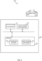
- FIG. 1 shows a block diagram of one example of an apparatus 100 which may be implemented as any form of a computing device and/or electronic device that incorporates a digital image capture unit or a digital imaging system.
- the apparatus 100 may be implemented as a stand-alone digital camera device, e.g. a compact camera, a SLR camera, or a mirrorless interchangeable-lens camera, or the apparatus 100 may be implemented e.g. as a smartphone, a tablet computer, a wearable camera or a web camera.
- the apparatus 100 comprises an illumination unit 106.
- the illumination unit 106 is configured to simultaneously illuminate a first portion of a scene with unstructured light and a second portion of the scene with structured light.
- the second portion of the scene may overlap the first portion of the scene partially, completely, or not at all.
- the unstructured light and/or the structured light may comprise light invisible to human eye, such as infrared light or ultraviolet light.
- the illumination unit 106 may be implemented e.g. as light-emitting diode (LED).
- the illumination unit 106 may comprise a diffractive optical element (DOE) 107 that is configured to provide the structured light.
- the diffractive optical element 107 may be switchable.
- the diffractive optical element 107 may be implemented e.g. as a lens that may be installed e.g. in front of the illumination unit 106 so that the light emitting from the illumination unit 106 passes through the lens.
- the diffractive optical element 107 may comprise a first part configured to allow the light emitting from the illumination unit 106 pass through unaltered, thereby providing the unstructured light.
- the diffractive optical element 107 may further comprise a second part configured to cause predetermined patterns in the light emitting from the illumination unit 106, thereby providing the structured light.
- the apparatus 100 further comprises a digital image capture unit 105.
- the digital image capture unit 105 is configured to capture at least one image frame of the illuminated scene.
- the digital image capture unit 105 may comprise at least an optical system including a lens arrangement and an image sensor, such as a charge-coupled device (CCD) sensor or a complementary metal-oxide-semiconductor (CMOS) sensor.
- CMOS complementary metal-oxide-semiconductor
- the digital image capture unit 105 further comprises a rolling shutter.
- the scene may comprise a region of interest, and the illumination unit 106 may be further configured to illuminate the region of interest with higher power than the rest of the scene.
- FIG. 2 shows a block diagram of one example of a system 200.
- the system 200 comprises an apparatus 210 which may be implemented as any form of a computing device and/or electronic device that incorporates a digital image capture unit or a digital imaging system.
- the apparatus 210 may be implemented as a stand-alone digital camera device, e.g. a compact camera, a SLR camera, or a mirrorless interchangeable-lens camera, or the apparatus 210 may be implemented e.g. as a smartphone, a tablet computer, a wearable camera or a web camera.
- the system 200 comprises an illumination unit 220.
- the illumination unit 220 is configured to simultaneously illuminate a first portion of a scene with unstructured light and a second portion of the scene with structured light.
- the second portion of the scene may overlap the first portion of the scene partially, completely, or not at all.
- the unstructured light and/or the structured light may comprise light invisible to human eye, such as infrared light or ultraviolet light.
- the illumination unit 220 may be implemented e.g. as light-emitting diode (LED).
- the illumination unit 220 is re-attachable to the apparatus 210.
- the illumination unit 220 may comprise a diffractive optical element (DOE) 221 that is configured to provide the structured light.
- the diffractive optical element 221 may be switchable.
- the diffractive optical element 221 may be implemented e.g. as a lens that may be installed e.g. in front of the illumination unit 220 so that the light emitting from the illumination unit 220 passes through the lens.
- the diffractive optical element 221 may comprise a first part configured to allow the light emitting from the illumination unit 220 pass through unaltered, thereby providing the unstructured light.
- the diffractive optical element 221 may further comprise a second part configured to cause predetermined pattern(s) in the light emitting from the illumination unit 220, thereby providing the structured light.
- the apparatus 210 further comprises a digital image capture unit 215.
- the digital image capture unit 215 is configured to capture at least one image frame of the illuminated scene.
- the digital image capture unit 215 may comprise at least an optical system including a lens arrangement and an image sensor, such as a charge-coupled device (CCD) sensor or a complementary metal-oxide-semiconductor (CMOS) sensor.
- CMOS complementary metal-oxide-semiconductor
- the digital image capture unit 215 further comprises a rolling shutter.
- the scene may comprise a region of interest, and the illumination unit 220 may be further configured to illuminate the region of interest with higher power than the rest of the scene.
- the apparatuses 100, 210 may comprise one or more processors 101, 211 which may be microprocessors, controllers or any other suitable type of processors for processing computer executable instructions to control the operation of the apparatuses 100, 210.
- Platform software comprising an operating system 103, 213 or any other suitable platform software may be provided at the apparatuses 100, 210 to enable application software 104, 214 to be executed on the device.
- Computer executable instructions may be provided using any computer-readable media that is accessible by the apparatuses 100, 210.
- Computer-readable media may include, for example, computer storage media such as memory 102 and communications media.
- Computer storage media, such as memory 102, 212 includes volatile and non-volatile, removable and non-removable media implemented in any method or technology for storage of information such as computer readable instructions, data structures, program modules or other data.
- Computer storage media includes, but is not limited to, RAM, ROM, EPROM, EEPROM, flash memory or other memory technology, CD-ROM, digital versatile disks (DVD) or other optical storage, magnetic cassettes, magnetic tape, magnetic disk storage or other magnetic storage devices, or any other non-transmission medium that can be used to store information for access by a computing device.
- communication media may embody computer readable instructions, data structures, program modules, or other data in a modulated data signal, such as a carrier wave, or other transport mechanism.
- computer storage media does not include communication media. Therefore, a computer storage medium should not be interpreted to be a propagating signal per se. Propagated signals may be present in a computer storage media, but propagated signals per se are not examples of computer storage media.
- the computer storage media memory 102, 212
- the storage may be distributed or located remotely and accessed via a network or other communication link.
- FIG. 3 shows a method which can be used to simultaneously illuminate a scene with both unstructured light and structured light.
- a first portion of a scene is illuminated with unstructured light using a single illumination unit, and simultaneously a second portion of the scene is illuminated with structured light using the same illumination unit.
- at least one image frame of the illuminated scene is captured using a digital image capture unit.
- the second portion of the scene may overlap the first portion of the scene partially, completely, or not at all.
- the unstructured light and/or the structured light may comprise light invisible to human eye, such as infrared light or ultraviolet light.
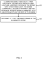
- FIG. 4 shows a method which can be used to simultaneously illuminate a scene with both unstructured light and structured light.
- a first portion of a scene is illuminated with unstructured light using a single illumination unit, and simultaneously a second portion of the scene is illuminated with structured light using the same illumination unit.
- the scene comprises a region of interest
- the illuminating step 400 comprises illuminating the region of interest with higher power than the rest of the scene.
- At step 402 at least one image frame of the illuminated scene is captured using a digital image capture unit.
- the second portion of the scene may overlap the first portion of the scene partially, completely, or not at all.
- the unstructured light and/or the structured light may comprise light invisible to human eye, such as infrared light or ultraviolet light.
- FIG. 5 shows a method which can be used to simultaneously illuminate a scene with both unstructured light and structured light.
- a first portion of a scene is illuminated with unstructured light using a single illumination unit, and simultaneously a second portion of the scene is illuminated with structured light using the same illumination unit.
- the unstructured light is utilized in iris recognition and the structured light is utilized in depth calculation.
- At step 502 at least one image frame of the illuminated scene is captured using a digital image capture unit.
- the second portion of the scene may overlap the first portion of the scene partially, completely, or not at all.
- the unstructured light and/or the structured light may comprise light invisible to human eye, such as infrared light or ultraviolet light.
- FIG. 6 illustrates a scene 600 that comprises a human face 610.
- the first portion 611 illuminated with the unstructured light is an area around the eyes and the second portion 612 illuminated with the structured light is an area around the first portion.
- the second portion 612 of the scene 600 may overlap the first portion 61 1 of the scene 600 partially, completely, or not at all.
- the unstructured light may be utilized e.g. in iris recognition and the structured light may be utilized e.g. in depth calculation.
- Iris recognition typically utilizes an infrared illumination unit and digital image capture unit matching the IR wavelengths.
- near-infrared (R) is used.
- R near-infrared
- a human eye can usually see also some part of the NIR radiation, so a NIR illumination unit may be visible to users.
- NIR wavelength is close to red color (i.e. close to 800 nm)
- the NIR illumination unit may actually look like a normal red LED.
- IR radiation may be harmful for the eye, if power is high and/or exposure time is long.
- FIG. 7 allows reducing the average power emitting from the illumination unit. Reducing average power level may facilitate making e.g. an IR illumination unit less visible/irritating and less harmful for the eyes. Furthermore, if required IR energy for a proper exposure at distance x is 100%, then due to the inverse square law, required IR energy at 2x distance is 400%. Accordingly, being able to reduce the average power emitting from the illumination unit is beneficial.
- FIGS. 1-7 are able to provide simultaneous illumination of a scene with both unstructured light and structured light using a single illumination unit.
- the unstructured light may be utilized e.g. in iris recognition and the structured light may be utilized e.g. in depth calculation.
- depth information may be utilized for optimization of image capture parameters, such as to guide auto-focus, auto-exposure and/or illumination unit control.
- depth information may be utilized for safety decisions, such as for turning off the illumination unit when a face comes closer to the apparatus than a predetermined threshold.
- depth information may be utilized for power optimizations, such as for detecting when there is nothing in front of the apparatus and in response turning the illumination unit power off/lower.
- depth information may be utilized for e.g. removing/blurring a background in a video call.
- FIGS. 1-7 may be used underwater and/or in darkness, since they do not rely on external light sources, such as sunlight or room lighting.
- the apparatus comprises a mobile communication device.
- An embodiment of a computer-readable storage medium not according to the claimed invention comprises executable instructions for causing at least one processor of an apparatus to perform operations comprising: illuminating, with an illumination unit, simultaneously a first portion of a scene with unstructured light and a second portion of the scene with structured light; and capturing, with a digital image capture unit, at least one image frame of the illuminated scene.
- 'computer' or 'computing-based device' is used herein to refer to any device with processing capability such that it can execute instructions. Those skilled in the art will realize that such processing capabilities are incorporated into many different devices and therefore the terms 'computer' and 'computing-based device' each include mobile telephones (including smart phones), tablet computers and many other devices.
- the methods described herein may be performed by software in machine readable form on a tangible storage medium e.g. in the form of a computer program comprising computer program code means adapted to perform all the steps of any of the methods described herein when the program is run on a computer and where the computer program may be embodied on a computer readable medium.
- tangible storage media include computer storage devices comprising computer-readable media such as disks, thumb drives, memory etc. and do not include propagated signals. Propagated signals may be present in a tangible storage media, but propagated signals per se are not examples of tangible storage media.
- the software can be suitable for execution on a parallel processor or a serial processor such that the method steps may be carried out in any suitable order, or simultaneously.
- a remote computer may store an example of the process described as software.
- a local or terminal computer may access the remote computer and download a part or all of the software to run the program.
- the local computer may download pieces of the software as needed, or execute some software instructions at the local terminal and some at the remote computer (or computer network).
- a dedicated circuit such as a DSP, programmable logic array, or the like.
Landscapes
- Engineering & Computer Science (AREA)
- Theoretical Computer Science (AREA)
- Physics & Mathematics (AREA)
- General Physics & Mathematics (AREA)
- Multimedia (AREA)
- Health & Medical Sciences (AREA)
- General Health & Medical Sciences (AREA)
- Ophthalmology & Optometry (AREA)
- Human Computer Interaction (AREA)
- Computer Vision & Pattern Recognition (AREA)
- Signal Processing (AREA)
- Measurement Of The Respiration, Hearing Ability, Form, And Blood Characteristics Of Living Organisms (AREA)
- Image Input (AREA)
- Studio Devices (AREA)
Description
- Infrared (IR) light is sometimes used in digital photography as it is invisible to human eye. Even though IR light may be filtered out in traditional photography, camera sensors are able to detect and measure it. For example, "night vision" in video cameras may utilize IR light to illuminate a scene. Also, IR light may be used for computer vision especially in low-light conditions in order to get more robust illumination than is possible with visible light.
- In
WO 2013/009235 A1 regions of interest may be illuminated upon image acquisition. - This Summary is provided to introduce a selection of concepts in a simplified form that are further described below in the Detailed Description. This Summary is not intended to identify key features or essential features of the claimed subject matter, nor is it intended to be used to limit the scope of the claimed subject matter.
- In one example, an apparatus comprises an illumination unit configured to simultaneously illuminate a first portion of a scene with unstructured light and a second portion of the scene with structured light; and a digital image capture unit configured to capture at least one image frame of the illuminated scene.
- In other examples, a system and a method have been discussed along with the features of the apparatus.
- Many of the attendant features will be more readily appreciated as the same becomes better understood by reference to the following detailed description considered in connection with the accompanying drawings.
- The present description will be better understood from the following detailed description read in light of the accompanying drawings, wherein:
-
FIG. 1 is a block diagram of one example of a apparatus; -
FIG. 2 is a block diagram of one example of a system; -
FIG. 3 is a flow diagram of one example of a method; -
FIG. 4 is a flow diagram of another example of a method; -
FIG. 5 is a flow diagram of another example of a method; -
FIG. 6 illustrates a scene comprising a human face with the first portion being an area around the eyes and the second portion being an area around the first portion and -
FIG. 7 is a diagram illustrating illumination of a region of interest with higher power than the rest of the scene. - Like reference numerals are used to designate like parts in the accompanying drawings.
- The detailed description provided below in connection with the appended drawings is intended as a description of the present examples and is not intended to represent the only forms in which the present example may be constructed or utilized. The description sets forth the functions of the example and the sequence of steps for constructing and operating the example. However, the same or equivalent functions and sequences may be accomplished by different examples.
- Although some of the present examples may be described and illustrated herein as being implemented in a smartphone or a tablet computer, these are only examples of an apparatus and not a limitation. As those skilled in the art will appreciate the present examples are suitable for application in a variety of different types of apparatuses incorporating a digital image capture unit or a digital imaging system, for example, a stand-alone digital camera device, e.g. a compact camera, a SLR (Single-Lens Reflex) camera, or a mirrorless interchangeable-lens camera.
-
FIG. 1 shows a block diagram of one example of anapparatus 100 which may be implemented as any form of a computing device and/or electronic device that incorporates a digital image capture unit or a digital imaging system. For example, theapparatus 100 may be implemented as a stand-alone digital camera device, e.g. a compact camera, a SLR camera, or a mirrorless interchangeable-lens camera, or theapparatus 100 may be implemented e.g. as a smartphone, a tablet computer, a wearable camera or a web camera. - The
apparatus 100 comprises anillumination unit 106. Theillumination unit 106 is configured to simultaneously illuminate a first portion of a scene with unstructured light and a second portion of the scene with structured light. The second portion of the scene may overlap the first portion of the scene partially, completely, or not at all. The unstructured light and/or the structured light may comprise light invisible to human eye, such as infrared light or ultraviolet light. Theillumination unit 106 may be implemented e.g. as light-emitting diode (LED). - The
illumination unit 106 may comprise a diffractive optical element (DOE) 107 that is configured to provide the structured light. The diffractiveoptical element 107 may be switchable. The diffractiveoptical element 107 may be implemented e.g. as a lens that may be installed e.g. in front of theillumination unit 106 so that the light emitting from theillumination unit 106 passes through the lens. The diffractiveoptical element 107 may comprise a first part configured to allow the light emitting from theillumination unit 106 pass through unaltered, thereby providing the unstructured light. The diffractiveoptical element 107 may further comprise a second part configured to cause predetermined patterns in the light emitting from theillumination unit 106, thereby providing the structured light. - The
apparatus 100 further comprises a digitalimage capture unit 105. The digitalimage capture unit 105 is configured to capture at least one image frame of the illuminated scene. The digitalimage capture unit 105 may comprise at least an optical system including a lens arrangement and an image sensor, such as a charge-coupled device (CCD) sensor or a complementary metal-oxide-semiconductor (CMOS) sensor. The digitalimage capture unit 105 further comprises a rolling shutter. The scene may comprise a region of interest, and theillumination unit 106 may be further configured to illuminate the region of interest with higher power than the rest of the scene. -
FIG. 2 shows a block diagram of one example of asystem 200. Thesystem 200 comprises anapparatus 210 which may be implemented as any form of a computing device and/or electronic device that incorporates a digital image capture unit or a digital imaging system. For example, theapparatus 210 may be implemented as a stand-alone digital camera device, e.g. a compact camera, a SLR camera, or a mirrorless interchangeable-lens camera, or theapparatus 210 may be implemented e.g. as a smartphone, a tablet computer, a wearable camera or a web camera. - The
system 200 comprises anillumination unit 220. Theillumination unit 220 is configured to simultaneously illuminate a first portion of a scene with unstructured light and a second portion of the scene with structured light. The second portion of the scene may overlap the first portion of the scene partially, completely, or not at all. The unstructured light and/or the structured light may comprise light invisible to human eye, such as infrared light or ultraviolet light. Theillumination unit 220 may be implemented e.g. as light-emitting diode (LED). Theillumination unit 220 is re-attachable to theapparatus 210. - The
illumination unit 220 may comprise a diffractive optical element (DOE) 221 that is configured to provide the structured light. The diffractiveoptical element 221 may be switchable. The diffractiveoptical element 221 may be implemented e.g. as a lens that may be installed e.g. in front of theillumination unit 220 so that the light emitting from theillumination unit 220 passes through the lens. The diffractiveoptical element 221 may comprise a first part configured to allow the light emitting from theillumination unit 220 pass through unaltered, thereby providing the unstructured light. The diffractiveoptical element 221 may further comprise a second part configured to cause predetermined pattern(s) in the light emitting from theillumination unit 220, thereby providing the structured light. - The
apparatus 210 further comprises a digitalimage capture unit 215. The digitalimage capture unit 215 is configured to capture at least one image frame of the illuminated scene. The digitalimage capture unit 215 may comprise at least an optical system including a lens arrangement and an image sensor, such as a charge-coupled device (CCD) sensor or a complementary metal-oxide-semiconductor (CMOS) sensor. The digitalimage capture unit 215 further comprises a rolling shutter. The scene may comprise a region of interest, and theillumination unit 220 may be further configured to illuminate the region of interest with higher power than the rest of the scene. - The
apparatuses more processors apparatuses operating system apparatuses application software - Computer executable instructions may be provided using any computer-readable media that is accessible by the
apparatuses memory 102 and communications media. Computer storage media, such asmemory memory 102, 212) is shown within theapparatuses -
FIG. 3 shows a method which can be used to simultaneously illuminate a scene with both unstructured light and structured light. Atstep 300, a first portion of a scene is illuminated with unstructured light using a single illumination unit, and simultaneously a second portion of the scene is illuminated with structured light using the same illumination unit. Atstep 302 at least one image frame of the illuminated scene is captured using a digital image capture unit. - As discussed above, the second portion of the scene may overlap the first portion of the scene partially, completely, or not at all. The unstructured light and/or the structured light may comprise light invisible to human eye, such as infrared light or ultraviolet light.
-
FIG. 4 shows a method which can be used to simultaneously illuminate a scene with both unstructured light and structured light. Atstep 400, a first portion of a scene is illuminated with unstructured light using a single illumination unit, and simultaneously a second portion of the scene is illuminated with structured light using the same illumination unit. - In the example of
FIG. 4 , the scene comprises a region of interest, and the illuminatingstep 400 comprises illuminating the region of interest with higher power than the rest of the scene. Atstep 402 at least one image frame of the illuminated scene is captured using a digital image capture unit. - As discussed above, the second portion of the scene may overlap the first portion of the scene partially, completely, or not at all. The unstructured light and/or the structured light may comprise light invisible to human eye, such as infrared light or ultraviolet light.
-
FIG. 5 shows a method which can be used to simultaneously illuminate a scene with both unstructured light and structured light. Atstep 500, a first portion of a scene is illuminated with unstructured light using a single illumination unit, and simultaneously a second portion of the scene is illuminated with structured light using the same illumination unit. - In the example of
FIG. 5 , the unstructured light is utilized in iris recognition and the structured light is utilized in depth calculation. Atstep 502 at least one image frame of the illuminated scene is captured using a digital image capture unit. - As discussed above, the second portion of the scene may overlap the first portion of the scene partially, completely, or not at all. The unstructured light and/or the structured light may comprise light invisible to human eye, such as infrared light or ultraviolet light.
-
FIG. 6 illustrates ascene 600 that comprises ahuman face 610. Thefirst portion 611 illuminated with the unstructured light is an area around the eyes and thesecond portion 612 illuminated with the structured light is an area around the first portion. Thesecond portion 612 of thescene 600 may overlap the first portion 61 1 of thescene 600 partially, completely, or not at all. Here, the unstructured light may be utilized e.g. in iris recognition and the structured light may be utilized e.g. in depth calculation. - The scene may comprise more than two portions, at least some of which may be illuminated with similar structured light as the second portion or with structured light having a different structure than that of the structured light illuminating the second portion. For example, a dense structure may be used on a portion requiring more accuracy and a sparse structure may be used on a portion requiring less accuracy.
-
FIG. 7 illustrates illumination of a region of interest with higher power than the rest of the scene. Thescene 700 comprises ahuman face 710. In addition to the scene having the first portion illuminated with the unstructured light and the second portion illuminated with the structured light, as discussed above, thescene 700 further comprises a region of interest 720 (ROI). InFIG. 7 related to iris recognition, the region ofinterest 720 includes eye area or iris area. The region ofinterest 720 may overlap the first portion of the scene and/or the second portion of the scene. -
Curve 730 represents power or current used to control the illumination unit or LED. The example ofFIG. 7 relates to a digital image capture unit comprising a rolling shutter. In other words, exposure and frame read-out starts from a top row, and bottom row exposure may start e.g. tens of milliseconds later than the top row one. Accordingly,lines 731 represent row exposure start, andlines 732 represent row exposure stop.Points 741 represent the moments of time when the illumination unit is turned on or to high power (i.e. when the rolling shutter exposure reaches the top of the ROI indicated by the upper dash line), and points 742 represent the moments of time when the illumination unit is turned off or to low power (i.e. when the rolling shutter exposure reaches the bottom of the ROI indicated by the lower dash line). - In
FIG. 7 , illumination unit or LED may be turned on and off synchronized to the frame read-out of the digital image capture unit so that only e.g. iris area (ROI) 720 is illuminated with high power. Alternatively, instead of turning the IR light on and off, it may be turned to high power and low power. This may be more convenient for the eyes, as illumination source flickering is not as visible if there is some light emitting all the time. For example, substantially 20% power may be used outside the ROI, whereas substantially 100% power may be used within the ROI. - Iris recognition typically utilizes an infrared illumination unit and digital image capture unit matching the IR wavelengths. Typically, near-infrared (R) is used. However, a human eye can usually see also some part of the NIR radiation, so a NIR illumination unit may be visible to users. Especially, if NIR wavelength is close to red color (i.e. close to 800 nm), the NIR illumination unit may actually look like a normal red LED. Furthermore, IR radiation may be harmful for the eye, if power is high and/or exposure time is long.
- The example of
FIG. 7 allows reducing the average power emitting from the illumination unit. Reducing average power level may facilitate making e.g. an IR illumination unit less visible/irritating and less harmful for the eyes. Furthermore, if required IR energy for a proper exposure at distance x is 100%, then due to the inverse square law, required IR energy at 2x distance is 400%. Accordingly, being able to reduce the average power emitting from the illumination unit is beneficial. - At least some of the examples disclosed in
FIGS. 1-7 are able to provide simultaneous illumination of a scene with both unstructured light and structured light using a single illumination unit. As discussed above, the unstructured light may be utilized e.g. in iris recognition and the structured light may be utilized e.g. in depth calculation. - This may provide more secure authentication, since on parallel with iris recognition it could be verified that the visible object has a three-dimensional (3D) shape of a face (i.e. it is not e.g. paper or display). Also, utilizing facial 3D information may provide more secure authentication. Furthermore, depth information may be utilized for optimization of image capture parameters, such as to guide auto-focus, auto-exposure and/or illumination unit control. Furthermore, depth information may be utilized for safety decisions, such as for turning off the illumination unit when a face comes closer to the apparatus than a predetermined threshold. Furthermore, depth information may be utilized for power optimizations, such as for detecting when there is nothing in front of the apparatus and in response turning the illumination unit power off/lower. Furthermore, depth information may be utilized for e.g. removing/blurring a background in a video call. Furthermore, at least some of the examples disclosed in
FIGS. 1-7 may be used underwater and/or in darkness, since they do not rely on external light sources, such as sunlight or room lighting. - In an embodiment, alternatively or in addition, the apparatus comprises a mobile communication device.
- An embodiment of a computer-readable storage medium not according to the claimed invention comprises executable instructions for causing at least one processor of an apparatus to perform operations comprising: illuminating, with an illumination unit, simultaneously a first portion of a scene with unstructured light and a second portion of the scene with structured light; and capturing, with a digital image capture unit, at least one image frame of the illuminated scene.
- The term 'computer' or 'computing-based device' is used herein to refer to any device with processing capability such that it can execute instructions. Those skilled in the art will realize that such processing capabilities are incorporated into many different devices and therefore the terms 'computer' and 'computing-based device' each include mobile telephones (including smart phones), tablet computers and many other devices.
- The methods described herein may be performed by software in machine readable form on a tangible storage medium e.g. in the form of a computer program comprising computer program code means adapted to perform all the steps of any of the methods described herein when the program is run on a computer and where the computer program may be embodied on a computer readable medium. Examples of tangible storage media include computer storage devices comprising computer-readable media such as disks, thumb drives, memory etc. and do not include propagated signals. Propagated signals may be present in a tangible storage media, but propagated signals per se are not examples of tangible storage media. The software can be suitable for execution on a parallel processor or a serial processor such that the method steps may be carried out in any suitable order, or simultaneously.
- This acknowledges that software can be a valuable, separately tradable commodity. It is intended to encompass software, which runs on or controls "dumb" or standard hardware, to carry out the desired functions. It is also intended to encompass software which "describes" or defines the configuration of hardware, such as HDL (hardware description language) software, as is used for designing silicon chips, or for configuring universal programmable chips, to carry out desired functions.
- Those skilled in the art will realize that storage devices utilized to store program instructions can be distributed across a network. For example, a remote computer may store an example of the process described as software. A local or terminal computer may access the remote computer and download a part or all of the software to run the program. Alternatively, the local computer may download pieces of the software as needed, or execute some software instructions at the local terminal and some at the remote computer (or computer network). Those skilled in the art will also realize that by utilizing conventional techniques known to those skilled in the art that all, or a portion of the software instructions may be carried out by a dedicated circuit, such as a DSP, programmable logic array, or the like.
- Any range or device value given herein may be extended or altered without losing the effect sought, as will be apparent to the skilled person, provided that they fall under the scope of the appended claims.
- Although the subject matter has been described in language specific to structural features and/or methodological acts, it is to be understood that the subject matter defined in the appended claims is not necessarily limited to the specific features or acts described above. Rather, the specific features and acts described above are disclosed as example forms of implementing the claims.
- It will be understood that the benefits and advantages described above may relate to one embodiment or may relate to several embodiments. The embodiments are not limited to those that solve any or all of the stated problems or those that have any or all of the stated benefits and advantages. It will further be understood that reference to 'an' item refers to one or more of those items.
- The steps of the methods described herein may be carried out in any suitable order, or simultaneously where appropriate. Additionally, individual blocks may be deleted from any of the methods without departing from the spirit and scope of the subject matter described herein. Aspects of any of the examples described above may be combined with aspects of any of the other examples described to form further examples without losing the effect sought.
- The term 'comprising' is used herein to mean including the method blocks or elements identified, but that such blocks or elements do not comprise an exclusive list and a method or apparatus may contain additional blocks or elements.
- It will be understood that the above description is given by way of example only and that various modifications may be made by those skilled in the art. The above specification, examples and data provide a complete description of the structure and use of exemplary embodiments. Although various embodiments have been described above with a certain degree of particularity, or with reference to one or more individual embodiments, those skilled in the art could make numerous alterations to the disclosed examples, provided that they fall under the scope of the claims.
Claims (10)
- A method of capturing a face image, comprising:illuminating, with an illumination unit, simultaneously a first portion of a scene with unstructured light and a second portion of the scene with structured light;capturing, with a digital image capture unit that includes a rolling shutter, at least one image frame of the illuminated scene; andvia the illumination unit, selectively adjusting illumination of the scene based on a position of the rolling shutter to illuminate a region of interest of the scene, wherein the region of interest includes eye or iris area, with higher power than the rest of the scene by operating the illumination unit at a first, higher power setting responsive to an exposure of the rolling shutter being within the region of interest and by operating the illumination unit at a second, reduced power setting responsive to an exposure of the rolling shutter being outside the region of interest.
- The method as claimed in claim 1, further comprising at least one of utilizing the unstructured light in iris recognition and utilizing the structured light in depth calculation.
- An apparatus, comprising:an illumination unit configured to simultaneously illuminate a first portion of a scene with unstructured light and a second portion of the scene with structured light; and a digital image capture unit including a rolling shutter and being configured to capture at least one image frame of the illuminated scene,wherein the scene comprises a region of interest, wherein the region of interest includes eye or iris area, and the illumination unit is configured to selectively adjust illumination of the scene based on a position of the rolling shutter to illuminate the region of interest of the scene with higher power than the rest of the scene by operating the illumination unit at a first, higher power setting responsive to an exposure of the rolling shutter being within the region of interest and by operating the illumination unit at a second, reduced power setting responsive to an exposure of the rolling shutter being outside the region of interest.
- The apparatus as claimed in claim 3, wherein the second portion of the scene overlaps the first portion of the scene at least partially.
- The apparatus as claimed in any of claims 3-4, wherein the illumination unit comprises a diffractive optical element configured to provide the structured light.
- The apparatus as claimed in claim 5, wherein the diffractive optical element is switchable.
- The apparatus as claimed in any of claims 3-6, wherein the first portion of the scene comprises a human eye and the unstructured light is utilized in iris recognition.
- The apparatus as claimed in any of claims 3-7, wherein the structured light is utilized in depth calculation.
- The apparatus as claimed in any of claims 3-8, wherein at least one of the unstructured light and the structured light comprises light invisible to human eye.
- The apparatus as claimed in claim 9, wherein the invisible light comprises one of infrared light and ultraviolet light.
Applications Claiming Priority (2)
| Application Number | Priority Date | Filing Date | Title |
|---|---|---|---|
| US14/636,408 US9953428B2 (en) | 2015-03-03 | 2015-03-03 | Digital camera unit with simultaneous structured and unstructured illumination |
| PCT/US2016/017048 WO2016140774A1 (en) | 2015-03-03 | 2016-02-09 | Digital camera unit with simultaneous structured and unstructured illumination |
Publications (2)
| Publication Number | Publication Date |
|---|---|
| EP3265957A1 EP3265957A1 (en) | 2018-01-10 |
| EP3265957B1 true EP3265957B1 (en) | 2024-12-04 |
Family
ID=55587324
Family Applications (1)
| Application Number | Title | Priority Date | Filing Date |
|---|---|---|---|
| EP16711034.5A Active EP3265957B1 (en) | 2015-03-03 | 2016-02-09 | Digital camera unit with simultaneous structured and unstructured illumination |
Country Status (4)
| Country | Link |
|---|---|
| US (1) | US9953428B2 (en) |
| EP (1) | EP3265957B1 (en) |
| CN (1) | CN107408201B (en) |
| WO (1) | WO2016140774A1 (en) |
Families Citing this family (20)
| Publication number | Priority date | Publication date | Assignee | Title |
|---|---|---|---|---|
| US20160350607A1 (en) * | 2015-05-26 | 2016-12-01 | Microsoft Technology Licensing, Llc | Biometric authentication device |
| US10547829B2 (en) * | 2016-06-16 | 2020-01-28 | Samsung Electronics Co., Ltd. | Image detecting device and image detecting method using the same |
| US10241244B2 (en) | 2016-07-29 | 2019-03-26 | Lumentum Operations Llc | Thin film total internal reflection diffraction grating for single polarization or dual polarization |
| US10372974B2 (en) | 2017-01-11 | 2019-08-06 | Microsoft Technology Licensing, Llc | 3D imaging recognition by stereo matching of RGB and infrared images |
| US10204262B2 (en) * | 2017-01-11 | 2019-02-12 | Microsoft Technology Licensing, Llc | Infrared imaging recognition enhanced by 3D verification |
| US11151235B2 (en) | 2017-08-01 | 2021-10-19 | Apple Inc. | Biometric authentication techniques |
| EP3662411B1 (en) * | 2017-08-01 | 2024-10-09 | Apple Inc. | Biometric authentication techniques |
| US10535151B2 (en) * | 2017-08-22 | 2020-01-14 | Microsoft Technology Licensing, Llc | Depth map with structured and flood light |
| US20190068853A1 (en) * | 2017-08-22 | 2019-02-28 | Microsoft Technology Licensing, Llc | Structured light and flood fill light illuminator |
| CN108683902B (en) * | 2018-03-31 | 2020-06-30 | 深圳奥比中光科技有限公司 | Target image acquisition system and method |
| CN108648225B (en) | 2018-03-31 | 2022-08-02 | 奥比中光科技集团股份有限公司 | Target image acquisition system and method |
| EP3824621B1 (en) | 2018-07-19 | 2025-06-11 | Activ Surgical, Inc. | Systems and methods for multi-modal sensing of depth in vision systems for automated surgical robots |
| US10990805B2 (en) * | 2018-09-12 | 2021-04-27 | Apple Inc. | Hybrid mode illumination for facial recognition authentication |
| KR102661955B1 (en) | 2018-12-12 | 2024-04-29 | 삼성전자주식회사 | Method and apparatus of processing image |
| EP3902458A4 (en) | 2018-12-28 | 2022-09-21 | Activ Surgical, Inc. | USER INTERFACE ELEMENTS FOR ORIENTATING A REMOTE CAMERA DURING A SURGICAL PROCEDURE |
| JP2022516473A (en) | 2018-12-28 | 2022-02-28 | アクティブ サージカル, インコーポレイテッド | Systems and methods for optimizing reachability, workspace, and sophistication in minimally invasive surgery |
| US12292564B2 (en) | 2019-04-08 | 2025-05-06 | Activ Surgical, Inc. | Systems and methods for medical imaging |
| WO2020210168A1 (en) | 2019-04-08 | 2020-10-15 | Activ Surgical, Inc. | Systems and methods for medical imaging |
| WO2020214821A1 (en) | 2019-04-19 | 2020-10-22 | Activ Surgical, Inc. | Systems and methods for trocar kinematics |
| EP4017340A4 (en) | 2019-08-21 | 2023-12-13 | Activ Surgical, Inc. | SYSTEMS AND METHODS FOR MEDICAL IMAGING |
Family Cites Families (23)
| Publication number | Priority date | Publication date | Assignee | Title |
|---|---|---|---|---|
| US6714665B1 (en) | 1994-09-02 | 2004-03-30 | Sarnoff Corporation | Fully automated iris recognition system utilizing wide and narrow fields of view |
| CA2300605A1 (en) | 2000-03-14 | 2001-09-14 | Silent Witness Enterprises Ltd. | Infrared illuminator housing and assembly |
| US6850872B1 (en) | 2000-08-30 | 2005-02-01 | Microsoft Corporation | Facial image processing methods and systems |
| US8723118B2 (en) | 2009-10-01 | 2014-05-13 | Microsoft Corporation | Imager for constructing color and depth images |
| US11657606B2 (en) | 2010-03-16 | 2023-05-23 | OMNIQ Corp. | Dynamic image capture and processing |
| EP2448251B1 (en) * | 2010-10-31 | 2019-09-25 | Mobileye Vision Technologies Ltd. | Bundling night vision and other driver assistance systems (DAS) using near infra red (NIR) illumination and a rolling shutter |
| US20120242795A1 (en) | 2011-03-24 | 2012-09-27 | Paul James Kane | Digital 3d camera using periodic illumination |
| US9176608B1 (en) * | 2011-06-27 | 2015-11-03 | Amazon Technologies, Inc. | Camera based sensor for motion detection |
| EP2581034B1 (en) * | 2011-10-11 | 2016-02-17 | Tobii AB | Eye-tracker illumination |
| DE102011114500B4 (en) | 2011-09-29 | 2022-05-05 | Fei Company | microscope device |
| JP2013105272A (en) | 2011-11-11 | 2013-05-30 | Canon Inc | Display control device and method, program, and storage medium |
| US9063574B1 (en) * | 2012-03-14 | 2015-06-23 | Amazon Technologies, Inc. | Motion detection systems for electronic devices |
| GB201205303D0 (en) * | 2012-03-26 | 2012-05-09 | Light Blue Optics Ltd | Touch sensing systems |
| US9141868B2 (en) | 2012-06-26 | 2015-09-22 | Xerox Corporation | Contemporaneously reconstructing images captured of a scene illuminated with unstructured and structured illumination sources |
| CN102848786B (en) * | 2012-07-20 | 2015-09-16 | 中国科学院上海光学精密机械研究所 | Three-dimensional identity card and preparation method thereof |
| US20140118257A1 (en) * | 2012-10-29 | 2014-05-01 | Amazon Technologies, Inc. | Gesture detection systems |
| US10009579B2 (en) | 2012-11-21 | 2018-06-26 | Pelco, Inc. | Method and system for counting people using depth sensor |
| US9013536B2 (en) | 2013-03-13 | 2015-04-21 | Futurewei Technologies, Inc. | Augmented video calls on mobile devices |
| US20150276400A1 (en) * | 2013-03-13 | 2015-10-01 | Electronic Scripting Products, Inc. | Reduced homography for ascertaining conditioned motion of an optical apparatus |
| US9852512B2 (en) * | 2013-03-13 | 2017-12-26 | Electronic Scripting Products, Inc. | Reduced homography based on structural redundancy of conditioned motion |
| US8970709B2 (en) * | 2013-03-13 | 2015-03-03 | Electronic Scripting Products, Inc. | Reduced homography for recovery of pose parameters of an optical apparatus producing image data with structural uncertainty |
| US11172126B2 (en) | 2013-03-15 | 2021-11-09 | Occipital, Inc. | Methods for reducing power consumption of a 3D image capture system |
| US10419703B2 (en) * | 2014-06-20 | 2019-09-17 | Qualcomm Incorporated | Automatic multiple depth cameras synchronization using time sharing |
-
2015
- 2015-03-03 US US14/636,408 patent/US9953428B2/en active Active
-
2016
- 2016-02-09 WO PCT/US2016/017048 patent/WO2016140774A1/en not_active Ceased
- 2016-02-09 EP EP16711034.5A patent/EP3265957B1/en active Active
- 2016-02-09 CN CN201680013329.9A patent/CN107408201B/en active Active
Also Published As
| Publication number | Publication date |
|---|---|
| EP3265957A1 (en) | 2018-01-10 |
| CN107408201B (en) | 2020-09-22 |
| US20160260223A1 (en) | 2016-09-08 |
| WO2016140774A1 (en) | 2016-09-09 |
| CN107408201A (en) | 2017-11-28 |
| US9953428B2 (en) | 2018-04-24 |
Similar Documents
| Publication | Publication Date | Title |
|---|---|---|
| EP3265957B1 (en) | Digital camera unit with simultaneous structured and unstructured illumination | |
| US11330199B2 (en) | Method and system of adaptable exposure control and light projection for cameras | |
| KR102270674B1 (en) | Biometric camera | |
| CN104253947B (en) | Smart camera flash lamp | |
| US10373008B2 (en) | Systems and methods of biometric analysis with adaptive trigger | |
| CN104394306A (en) | Multi-channel multi-zone coated camera module and equipment for iris recognition | |
| US10609265B2 (en) | Methods and apparatus for synchronizing camera flash and sensor blanking | |
| KR102506363B1 (en) | A device with exactly two cameras and how to create two images using the device | |
| US20160350607A1 (en) | Biometric authentication device | |
| US10853641B2 (en) | Apparatus and method for acquiring iris image outdoors and indoors | |
| US20140160317A1 (en) | Method and apparatus for photographing an image using light from multiple light sources | |
| US9906705B2 (en) | Image pickup apparatus | |
| JP6525723B2 (en) | Imaging device, control method therefor, program, and storage medium | |
| JP5470218B2 (en) | Imaging device | |
| US20250301228A1 (en) | Systems and Methods for Detection and Mitigation of a Rolling Band using a Secondary Camera | |
| JP6508889B2 (en) | Imaging device, control method for imaging device and program | |
| US20210067662A1 (en) | 3d active depth sensing with laser pulse train bursts and a gated sensor | |
| WO2025071563A1 (en) | Systems and methods for detection and mitigation of a rolling band | |
| JP6512806B2 (en) | Imaging device | |
| KR20130090586A (en) | Cognition apparatus for multi touch and control method thereof | |
| JP2016004133A (en) | Imaging device and control method of the same, program, and memory medium | |
| JP2015045771A (en) | Digital camera | |
| JP2014116656A (en) | Imaging apparatus, imaging method and program |
Legal Events
| Date | Code | Title | Description |
|---|---|---|---|
| STAA | Information on the status of an ep patent application or granted ep patent |
Free format text: STATUS: THE INTERNATIONAL PUBLICATION HAS BEEN MADE |
|
| PUAI | Public reference made under article 153(3) epc to a published international application that has entered the european phase |
Free format text: ORIGINAL CODE: 0009012 |
|
| STAA | Information on the status of an ep patent application or granted ep patent |
Free format text: STATUS: REQUEST FOR EXAMINATION WAS MADE |
|
| 17P | Request for examination filed |
Effective date: 20170804 |
|
| AK | Designated contracting states |
Kind code of ref document: A1 Designated state(s): AL AT BE BG CH CY CZ DE DK EE ES FI FR GB GR HR HU IE IS IT LI LT LU LV MC MK MT NL NO PL PT RO RS SE SI SK SM TR |
|
| AX | Request for extension of the european patent |
Extension state: BA ME |
|
| DAV | Request for validation of the european patent (deleted) | ||
| DAX | Request for extension of the european patent (deleted) | ||
| STAA | Information on the status of an ep patent application or granted ep patent |
Free format text: STATUS: EXAMINATION IS IN PROGRESS |
|
| 17Q | First examination report despatched |
Effective date: 20210317 |
|
| RAP3 | Party data changed (applicant data changed or rights of an application transferred) |
Owner name: MICROSOFT TECHNOLOGY LICENSING, LLC |
|
| REG | Reference to a national code |
Ref country code: DE Ref legal event code: R079 Free format text: PREVIOUS MAIN CLASS: G06K0009000000 Ipc: G06V0010141000 Ref country code: DE Ref legal event code: R079 Ref document number: 602016090491 Country of ref document: DE Free format text: PREVIOUS MAIN CLASS: G06K0009000000 Ipc: G06V0010141000 |
|
| GRAP | Despatch of communication of intention to grant a patent |
Free format text: ORIGINAL CODE: EPIDOSNIGR1 |
|
| STAA | Information on the status of an ep patent application or granted ep patent |
Free format text: STATUS: GRANT OF PATENT IS INTENDED |
|
| RIC1 | Information provided on ipc code assigned before grant |
Ipc: G06V 40/19 20220101ALI20240627BHEP Ipc: G06T 7/586 20170101ALI20240627BHEP Ipc: G06V 10/141 20220101AFI20240627BHEP |
|
| INTG | Intention to grant announced |
Effective date: 20240717 |
|
| GRAS | Grant fee paid |
Free format text: ORIGINAL CODE: EPIDOSNIGR3 |
|
| GRAA | (expected) grant |
Free format text: ORIGINAL CODE: 0009210 |
|
| STAA | Information on the status of an ep patent application or granted ep patent |
Free format text: STATUS: THE PATENT HAS BEEN GRANTED |
|
| AK | Designated contracting states |
Kind code of ref document: B1 Designated state(s): AL AT BE BG CH CY CZ DE DK EE ES FI FR GB GR HR HU IE IS IT LI LT LU LV MC MK MT NL NO PL PT RO RS SE SI SK SM TR |
|
| REG | Reference to a national code |
Ref country code: GB Ref legal event code: FG4D |
|
| REG | Reference to a national code |
Ref country code: CH Ref legal event code: EP |
|
| REG | Reference to a national code |
Ref country code: DE Ref legal event code: R096 Ref document number: 602016090491 Country of ref document: DE |
|
| REG | Reference to a national code |
Ref country code: IE Ref legal event code: FG4D |
|
| REG | Reference to a national code |
Ref country code: LT Ref legal event code: MG9D |
|
| REG | Reference to a national code |
Ref country code: NL Ref legal event code: MP Effective date: 20241204 |
|
| PG25 | Lapsed in a contracting state [announced via postgrant information from national office to epo] |
Ref country code: HR Free format text: LAPSE BECAUSE OF FAILURE TO SUBMIT A TRANSLATION OF THE DESCRIPTION OR TO PAY THE FEE WITHIN THE PRESCRIBED TIME-LIMIT Effective date: 20241204 |
|
| PG25 | Lapsed in a contracting state [announced via postgrant information from national office to epo] |
Ref country code: FI Free format text: LAPSE BECAUSE OF FAILURE TO SUBMIT A TRANSLATION OF THE DESCRIPTION OR TO PAY THE FEE WITHIN THE PRESCRIBED TIME-LIMIT Effective date: 20241204 |
|
| PG25 | Lapsed in a contracting state [announced via postgrant information from national office to epo] |
Ref country code: BG Free format text: LAPSE BECAUSE OF FAILURE TO SUBMIT A TRANSLATION OF THE DESCRIPTION OR TO PAY THE FEE WITHIN THE PRESCRIBED TIME-LIMIT Effective date: 20241204 |
|
| PG25 | Lapsed in a contracting state [announced via postgrant information from national office to epo] |
Ref country code: ES Free format text: LAPSE BECAUSE OF FAILURE TO SUBMIT A TRANSLATION OF THE DESCRIPTION OR TO PAY THE FEE WITHIN THE PRESCRIBED TIME-LIMIT Effective date: 20241204 |
|
| PG25 | Lapsed in a contracting state [announced via postgrant information from national office to epo] |
Ref country code: NO Free format text: LAPSE BECAUSE OF FAILURE TO SUBMIT A TRANSLATION OF THE DESCRIPTION OR TO PAY THE FEE WITHIN THE PRESCRIBED TIME-LIMIT Effective date: 20250304 |
|
| PG25 | Lapsed in a contracting state [announced via postgrant information from national office to epo] |
Ref country code: LV Free format text: LAPSE BECAUSE OF FAILURE TO SUBMIT A TRANSLATION OF THE DESCRIPTION OR TO PAY THE FEE WITHIN THE PRESCRIBED TIME-LIMIT Effective date: 20241204 Ref country code: GR Free format text: LAPSE BECAUSE OF FAILURE TO SUBMIT A TRANSLATION OF THE DESCRIPTION OR TO PAY THE FEE WITHIN THE PRESCRIBED TIME-LIMIT Effective date: 20250305 |
|
| PG25 | Lapsed in a contracting state [announced via postgrant information from national office to epo] |
Ref country code: RS Free format text: LAPSE BECAUSE OF FAILURE TO SUBMIT A TRANSLATION OF THE DESCRIPTION OR TO PAY THE FEE WITHIN THE PRESCRIBED TIME-LIMIT Effective date: 20250304 |
|
| PG25 | Lapsed in a contracting state [announced via postgrant information from national office to epo] |
Ref country code: NL Free format text: LAPSE BECAUSE OF FAILURE TO SUBMIT A TRANSLATION OF THE DESCRIPTION OR TO PAY THE FEE WITHIN THE PRESCRIBED TIME-LIMIT Effective date: 20241204 |
|
| REG | Reference to a national code |
Ref country code: AT Ref legal event code: MK05 Ref document number: 1748970 Country of ref document: AT Kind code of ref document: T Effective date: 20241204 |
|
| PG25 | Lapsed in a contracting state [announced via postgrant information from national office to epo] |
Ref country code: SM Free format text: LAPSE BECAUSE OF FAILURE TO SUBMIT A TRANSLATION OF THE DESCRIPTION OR TO PAY THE FEE WITHIN THE PRESCRIBED TIME-LIMIT Effective date: 20241204 |
|
| PG25 | Lapsed in a contracting state [announced via postgrant information from national office to epo] |
Ref country code: PL Free format text: LAPSE BECAUSE OF FAILURE TO SUBMIT A TRANSLATION OF THE DESCRIPTION OR TO PAY THE FEE WITHIN THE PRESCRIBED TIME-LIMIT Effective date: 20241204 |
|
| PG25 | Lapsed in a contracting state [announced via postgrant information from national office to epo] |
Ref country code: IS Free format text: LAPSE BECAUSE OF FAILURE TO SUBMIT A TRANSLATION OF THE DESCRIPTION OR TO PAY THE FEE WITHIN THE PRESCRIBED TIME-LIMIT Effective date: 20250404 |
|
| PG25 | Lapsed in a contracting state [announced via postgrant information from national office to epo] |
Ref country code: PT Free format text: LAPSE BECAUSE OF FAILURE TO SUBMIT A TRANSLATION OF THE DESCRIPTION OR TO PAY THE FEE WITHIN THE PRESCRIBED TIME-LIMIT Effective date: 20250404 |
|
| PG25 | Lapsed in a contracting state [announced via postgrant information from national office to epo] |
Ref country code: EE Free format text: LAPSE BECAUSE OF FAILURE TO SUBMIT A TRANSLATION OF THE DESCRIPTION OR TO PAY THE FEE WITHIN THE PRESCRIBED TIME-LIMIT Effective date: 20241204 |
|
| PG25 | Lapsed in a contracting state [announced via postgrant information from national office to epo] |
Ref country code: RO Free format text: LAPSE BECAUSE OF FAILURE TO SUBMIT A TRANSLATION OF THE DESCRIPTION OR TO PAY THE FEE WITHIN THE PRESCRIBED TIME-LIMIT Effective date: 20241204 Ref country code: AT Free format text: LAPSE BECAUSE OF FAILURE TO SUBMIT A TRANSLATION OF THE DESCRIPTION OR TO PAY THE FEE WITHIN THE PRESCRIBED TIME-LIMIT Effective date: 20241204 |
|
| PG25 | Lapsed in a contracting state [announced via postgrant information from national office to epo] |
Ref country code: SK Free format text: LAPSE BECAUSE OF FAILURE TO SUBMIT A TRANSLATION OF THE DESCRIPTION OR TO PAY THE FEE WITHIN THE PRESCRIBED TIME-LIMIT Effective date: 20241204 |
|
| PG25 | Lapsed in a contracting state [announced via postgrant information from national office to epo] |
Ref country code: CZ Free format text: LAPSE BECAUSE OF FAILURE TO SUBMIT A TRANSLATION OF THE DESCRIPTION OR TO PAY THE FEE WITHIN THE PRESCRIBED TIME-LIMIT Effective date: 20241204 |
|
| PG25 | Lapsed in a contracting state [announced via postgrant information from national office to epo] |
Ref country code: IT Free format text: LAPSE BECAUSE OF FAILURE TO SUBMIT A TRANSLATION OF THE DESCRIPTION OR TO PAY THE FEE WITHIN THE PRESCRIBED TIME-LIMIT Effective date: 20241204 |
|
| REG | Reference to a national code |
Ref country code: DE Ref legal event code: R097 Ref document number: 602016090491 Country of ref document: DE |
|
| PG25 | Lapsed in a contracting state [announced via postgrant information from national office to epo] |
Ref country code: SE Free format text: LAPSE BECAUSE OF FAILURE TO SUBMIT A TRANSLATION OF THE DESCRIPTION OR TO PAY THE FEE WITHIN THE PRESCRIBED TIME-LIMIT Effective date: 20241204 |
|
| PG25 | Lapsed in a contracting state [announced via postgrant information from national office to epo] |
Ref country code: MC Free format text: LAPSE BECAUSE OF FAILURE TO SUBMIT A TRANSLATION OF THE DESCRIPTION OR TO PAY THE FEE WITHIN THE PRESCRIBED TIME-LIMIT Effective date: 20241204 |
|
| REG | Reference to a national code |
Ref country code: CH Ref legal event code: PL |
|
| PG25 | Lapsed in a contracting state [announced via postgrant information from national office to epo] |
Ref country code: DK Free format text: LAPSE BECAUSE OF FAILURE TO SUBMIT A TRANSLATION OF THE DESCRIPTION OR TO PAY THE FEE WITHIN THE PRESCRIBED TIME-LIMIT Effective date: 20241204 |
|
| PLBE | No opposition filed within time limit |
Free format text: ORIGINAL CODE: 0009261 |
|
| STAA | Information on the status of an ep patent application or granted ep patent |
Free format text: STATUS: NO OPPOSITION FILED WITHIN TIME LIMIT |
|
| PG25 | Lapsed in a contracting state [announced via postgrant information from national office to epo] |
Ref country code: LU Free format text: LAPSE BECAUSE OF NON-PAYMENT OF DUE FEES Effective date: 20250209 |
|
| PG25 | Lapsed in a contracting state [announced via postgrant information from national office to epo] |
Ref country code: CH Free format text: LAPSE BECAUSE OF NON-PAYMENT OF DUE FEES Effective date: 20250228 |
|
| 26N | No opposition filed |
Effective date: 20250905 |
|
| REG | Reference to a national code |
Ref country code: BE Ref legal event code: MM Effective date: 20250228 |
|
| PG25 | Lapsed in a contracting state [announced via postgrant information from national office to epo] |
Ref country code: FR Free format text: LAPSE BECAUSE OF NON-PAYMENT OF DUE FEES Effective date: 20250228 |
|
| PG25 | Lapsed in a contracting state [announced via postgrant information from national office to epo] |
Ref country code: BE Free format text: LAPSE BECAUSE OF NON-PAYMENT OF DUE FEES Effective date: 20250228 |
|
| PG25 | Lapsed in a contracting state [announced via postgrant information from national office to epo] |
Ref country code: IE Free format text: LAPSE BECAUSE OF NON-PAYMENT OF DUE FEES Effective date: 20250209 |
|
| PGFP | Annual fee paid to national office [announced via postgrant information from national office to epo] |
Ref country code: GB Payment date: 20260121 Year of fee payment: 11 |
|
| PGFP | Annual fee paid to national office [announced via postgrant information from national office to epo] |
Ref country code: DE Payment date: 20260121 Year of fee payment: 11 |