EP3265869B1 - Eyewear frame having vents - Google Patents
Eyewear frame having vents Download PDFInfo
- Publication number
- EP3265869B1 EP3265869B1 EP16709634.6A EP16709634A EP3265869B1 EP 3265869 B1 EP3265869 B1 EP 3265869B1 EP 16709634 A EP16709634 A EP 16709634A EP 3265869 B1 EP3265869 B1 EP 3265869B1
- Authority
- EP
- European Patent Office
- Prior art keywords
- frame
- base frame
- eyewear
- upper member
- recesses
- Prior art date
- Legal status (The legal status is an assumption and is not a legal conclusion. Google has not performed a legal analysis and makes no representation as to the accuracy of the status listed.)
- Active
Links
Images



Classifications
-
- G—PHYSICS
- G02—OPTICS
- G02C—SPECTACLES; SUNGLASSES OR GOGGLES INSOFAR AS THEY HAVE THE SAME FEATURES AS SPECTACLES; CONTACT LENSES
- G02C11/00—Non-optical adjuncts; Attachment thereof
- G02C11/08—Anti-misting means, e.g. ventilating, heating; Wipers
-
- A—HUMAN NECESSITIES
- A61—MEDICAL OR VETERINARY SCIENCE; HYGIENE
- A61F—FILTERS IMPLANTABLE INTO BLOOD VESSELS; PROSTHESES; DEVICES PROVIDING PATENCY TO, OR PREVENTING COLLAPSING OF, TUBULAR STRUCTURES OF THE BODY, e.g. STENTS; ORTHOPAEDIC, NURSING OR CONTRACEPTIVE DEVICES; FOMENTATION; TREATMENT OR PROTECTION OF EYES OR EARS; BANDAGES, DRESSINGS OR ABSORBENT PADS; FIRST-AID KITS
- A61F9/00—Methods or devices for treatment of the eyes; Devices for putting in contact-lenses; Devices to correct squinting; Apparatus to guide the blind; Protective devices for the eyes, carried on the body or in the hand
- A61F9/02—Goggles
- A61F9/028—Ventilation means
-
- B—PERFORMING OPERATIONS; TRANSPORTING
- B29—WORKING OF PLASTICS; WORKING OF SUBSTANCES IN A PLASTIC STATE IN GENERAL
- B29C—SHAPING OR JOINING OF PLASTICS; SHAPING OF MATERIAL IN A PLASTIC STATE, NOT OTHERWISE PROVIDED FOR; AFTER-TREATMENT OF THE SHAPED PRODUCTS, e.g. REPAIRING
- B29C39/00—Shaping by casting, i.e. introducing the moulding material into a mould or between confining surfaces without significant moulding pressure; Apparatus therefor
- B29C39/02—Shaping by casting, i.e. introducing the moulding material into a mould or between confining surfaces without significant moulding pressure; Apparatus therefor for making articles of definite length, i.e. discrete articles
-
- B—PERFORMING OPERATIONS; TRANSPORTING
- B29—WORKING OF PLASTICS; WORKING OF SUBSTANCES IN A PLASTIC STATE IN GENERAL
- B29C—SHAPING OR JOINING OF PLASTICS; SHAPING OF MATERIAL IN A PLASTIC STATE, NOT OTHERWISE PROVIDED FOR; AFTER-TREATMENT OF THE SHAPED PRODUCTS, e.g. REPAIRING
- B29C39/00—Shaping by casting, i.e. introducing the moulding material into a mould or between confining surfaces without significant moulding pressure; Apparatus therefor
- B29C39/02—Shaping by casting, i.e. introducing the moulding material into a mould or between confining surfaces without significant moulding pressure; Apparatus therefor for making articles of definite length, i.e. discrete articles
- B29C39/12—Making multilayered or multicoloured articles
- B29C39/123—Making multilayered articles
-
- B—PERFORMING OPERATIONS; TRANSPORTING
- B29—WORKING OF PLASTICS; WORKING OF SUBSTANCES IN A PLASTIC STATE IN GENERAL
- B29K—INDEXING SCHEME ASSOCIATED WITH SUBCLASSES B29B, B29C OR B29D, RELATING TO MOULDING MATERIALS OR TO MATERIALS FOR MOULDS, REINFORCEMENTS, FILLERS OR PREFORMED PARTS, e.g. INSERTS
- B29K2995/00—Properties of moulding materials, reinforcements, fillers, preformed parts or moulds
- B29K2995/0037—Other properties
- B29K2995/007—Hardness
-
- B—PERFORMING OPERATIONS; TRANSPORTING
- B29—WORKING OF PLASTICS; WORKING OF SUBSTANCES IN A PLASTIC STATE IN GENERAL
- B29L—INDEXING SCHEME ASSOCIATED WITH SUBCLASS B29C, RELATING TO PARTICULAR ARTICLES
- B29L2012/00—Frames
- B29L2012/005—Spectacle frames
-
- G—PHYSICS
- G02—OPTICS
- G02C—SPECTACLES; SUNGLASSES OR GOGGLES INSOFAR AS THEY HAVE THE SAME FEATURES AS SPECTACLES; CONTACT LENSES
- G02C2200/00—Generic mechanical aspects applicable to one or more of the groups G02C1/00 - G02C5/00 and G02C9/00 - G02C13/00 and their subgroups
- G02C2200/08—Modular frames, easily exchangeable frame parts and lenses
Definitions
- the application relates generally to eyewear, and more particularly to an eyewear frame structure having vents and a method for making same.
- Eyewear including eyeglasses and goggles for various purposes conventionally include a frame structure made of substantially rigid material such as a rigid plastic material, with one or two lenses attached thereto.
- the frame structure is used to support the lens or lenses thereon and is configured in accordance with, and abuts the eyewear user's face around or near the eyes.
- the frame structure is retained on the user's head by a side piece or pieces, for example, temples or an elastic strap.
- Some eyewear such as eyeglasses or goggles for sports or safety may suffer to some degree from fogging of the lens or lenses due to the perspiration and warmth emanating from the user's face.
- vents in the eyewear frame structure to allow moisture and heat to escape from the space between the eyewear and the user's face.
- Efforts have been made to design vent structures which prevent foreign substances such as dust and liquids from flying through the vents and impacting the user's face or even entering the user's eyes.
- modern eyewear requires eyewear frame structures in complicated geometries and may be made of more than one material, which presents additional challenges for eyewear manufacturers to provide vents in such modern eyewear frame structures.
- US 2005/213025 A1 describes eyeglasses and a method of manufacture thereof, the eyeglass assembly includes an eyeglass frame having lens receptacles and a rib coupled to the eyeglass frame.
- US2011/122364 A1 describes an eye covering including an outer frame for surrounding a facial area around a wearer's eyes.
- US2011/001921 A1 describes an eyewear device including a frame having an eyewire and a ledge, with a plurality of chamber walls configured to allow air to circulate between opposite sides of the lens to reduce fogging.
- US2003/081169 A1 discloses eyewear for use in sports and the like which captures airflow impinging on the front of the eyewear, filters it to prevent the ingress of particulate matter, and then directs it through the dead space between the lenses and the wearer's eyes.
- an eyewear frame structure for holding at least one lens thereto, the eyewear frame structure comprising: a base frame including an upper member extending between opposed ends of the base frame, the opposed ends configured with respective enlarged end sections for providing pivotal connections to temples of the eyewear frame structure, and defining a groove in the front side of the upper member thereof, the groove extending along a length of the upper member; a front frame molded to the front side of the upper member of the base frame and thereby attached thereto, the front frame including an elongate member attached to a front side of the upper member of the base frame, the elongate member of the front frame being partially received in the groove of the base frame; a comfort bar molded to the base frame and thereby attached thereto, the comfort bar disposed on a back side of the upper member of the base frame; and a plurality of vent passages extending through the frame structure, each of the vent passages including a substantially horizontal section defined between the base frame and the front frame and a substantially vertical section defined between the base
- the substantially horizontal section of the vent passage comprises a top surface defined on the base frame and a bottom surface defined on the front frame
- the substantially vertical section of the vent passage comprises a front surface thereof defined on the base frame and a rear surface defined on the comfort bar.
- the elongate member of the front frame may comprise a plurality of spacers projecting upwardly from the elongate member to define a plurality of recesses between adjacent spacers, each of the recesses having a bottom defining a bottom surface of the substantially horizontal section of the vent passage.
- the groove in the upper member of the base frame may comprise a triangular cross section defining an upper surface and a lower surface of the groove
- each of the spacers of the front frame may comprise a triangular cross section defining a front-facing surface and a rear-facing surface, the rear-facing surface being in contact with the upper surface of the groove.
- the comfort bar may extend between and terminates at two opposed end sections of the base frame.
- the upper member of the base frame may define a plurality of first recesses in the groove, each of the first recesses being recessed rearwardly to define an opening on the upper surface of the groove and having an upper surface, the upper surface defining a top surface of the substantially horizontal section of each vent passage.
- the upper member of the base frame may define a plurality of second recesses on the back side thereof, each of the second recesses being recessed forwardly to define an inner surface and an opening on respective rear-facing and downward-facing surfaces of the upper member of the base frame, the second recesses being in communication with the respective first recesses, the inner surface of the second recess defining a front surface of the substantially vertical section of each vent passage.
- the comfort bar may cover the openings of the respective second recesses defined on the rear-facing surface, the openings of the second recesses defined on the downward-facing surface forming an opening of the substantially vertical section of the respective vent passages, a front surface of the comfort bar defining a rear surface of the substantially vertical section of each vent passage.
- the elongate member of the front frame and the upper member of the base frame may in combination define a groove therebetween, the groove extending along a length of the frame structure for receiving a section of an upper edge of the at least one lens.
- the front frame and the comfort bar may be flexible and soft relative to the base frame.
- a method for making an eyewear frame structure comprising steps of: a) molding the base frame structure; and b) with the presence of the molded base frame, molding the front frame to the front side of the upper member of the base frame and molding the comfort bar attached the a back side of the upper member of the base frame.
- molding the base frame structure may further include using a molding material which is rigid when cured, and wherein the front frame and the comfort bar are molded using a respective molding material which is flexible and soft relative to the rigid material of the base frame.
- the front frame and the comfort bar may be molded in one molding procedure using a same molding material.
- the front frame and the comfort bar may be molded in separate molding procedures using different molding materials.
- front and back/"rearward refer to directions from the perspective of the user - i.e. further away from the user's face is referred to as “front” or “forward” and closer to the user's face is referred to as “back” or “rear”.
- FIGS. 1 , 2 and 7 illustrate an eyewear frame structure 10 according to one embodiment, for holding at least one lens (shown in broken lines in FIG. 2 ) thereto.
- the eyewear frame structure 10 includes a base frame 12 which may be of a substantially rigid plastic material, a front frame 14 attached to a front side (not numbered) of the base frame 12, and a comfort bar 16 attached to a back side of the base frame 12.
- the front frame 14 and comfort bar 16 may be made of a material that is flexible and soft relative to the rigid plastic material of the base frame 12. Such flexible and soft material may for example, be rubber.
- the frame structure 10 may be configured in a curvature suitable for being worn on a user's head.
- the base frame 12 includes an upper member 18 extending between opposed ends 20 of the base frame 12, which is configured with respective enlarged end sections (not numbered) for providing, for example, suitable pivotal connections to temples (not shown) of the eyewear.
- the base frame 12 may include a connector 22 attached to a central portion of the upper member 18.
- the connector 22 may extend downwardly to support a pair of nose pieces 24 which are not part of the described subject matter and will not be further described hereinafter.
- the upper member 18 may therefore be formed as two similar sections, extending from the connector 22 toward the respective opposed ends 20. Due to the similarity of the two sections and for simplicity of description, only one section will be described in detail hereinafter.
- the upper member 18 of the base frame 12 defines a front side (not numbered) between a top surface 26 and a bottom surface 28 thereof, facing away from a user's face.
- the upper member 18 also defines a back side (not numbered) thereof between the top and bottom surfaces 26, 28, facing toward the user's face.
- the front side of the upper member 18 may include an upper ridge 30 and a lower ridge 32. Both upper and lower ridges 30, 32 project forwardly and extend along a length of the upper member 18 between the connector 22 and the corresponding enlarged end section.
- a groove 34 which may have a triangular cross-section, may therefore be formed between the upper and lower ridges 30 and 32, and extends along a length of the upper member 18, corresponding with the ridges 30, 32.
- the groove 34 may therefore be formed with an upper surface 36 and a lower surface 38 which in combination define the triangular cross-section of the groove 34.
- the back side of the upper member 18 may include two substantially vertical surfaces (which are referred to as a first rear-facing surface 40 and a second rear-facing surface 42) and a downward-facing surface 44 which in combination define a shoulder (not numbered) extending along a length of the upper member 18 on the back side thereof.
- Inclining transitional surfaces 46, 48 may be provided between the top surface 26 and the first rear-facing surface 40 and between the bottom surface 28 and the second rear-facing surface 42, respectively.
- the first rear-facing surface 40 may define a vertical dimension from the inclining transitional surface 46 to the downward-facing surface 44
- the upper member 18 may define a plurality of spaced apart first recesses 50 in the groove 34 (see FIG. 6 ).
- Each first recess 50 may define an opening 52 (see FIGS. 3 and 6 ) on the upper surface 36 of the groove 34 and may be recessed rearwardly to define side surfaces (not numbered, see FIG. 8 ) and an upper surface 54 (see FIG. 6 ). Therefore, the first recess 50 may have a triangular cross-section as shown in FIG. 6 .
- the upper member 18 may further define a plurality of second recesses 56 on the back side thereof.
- Each second recess 56 may define an opening 58 on the first rear-facing surface 40 and may be recessed forwardly to define side surfaces (not numbered, see FIG. 8 ) and an inner surface 60.
- the second recess 56 may be configured to have a vertical dimension corresponding to the vertical dimension of the first rear-facing surface 40, resulting in formation of another opening 62 of the second recess 56 in the downward-facing surface 44.
- the first recesses 50 may align with and be in fluid communication with respective second recesses 56. Therefore, a part of the inner surface 60 of the second recess 56 (as shown by broken lines in FIG. 6 ) may not exist and each first recess 50 and the corresponding second recess 56 in combination may form a passageway extending through the upper member 18 of the base frame 12 between the front and back sides thereof.
- the front frame 14 includes an elongate member 64.
- the elongate member 64 may have symmetrical right and left sections (not numbered) joined together by a center piece 65 which may be configured to correspond with and be attached to the connector 22 of the base frame 12.
- Each section of the elongate member 64 may include a flat strap 66 and a plurality of spacers 68 projecting upwardly from the flat strap 66 to define a plurality of recesses 70 between adjacent spacers 68.
- An upward-facing surface of the flat strap may form a bottom surface 72 of each recess 70.
- Each section of the elongate member 64 of the front frame 14 is partially received in the groove 34, which may be triangular, defined in the front side of the base frame 12.
- Each spacer 68 of the elongate member 64 may define a triangular cross-section including a front-facing surface 74 and rear-facing surface 76.
- the triangular cross-section of the spacer 68 may be configured such that the rear-facing surface 76 is in full contact with the upper surface 36 of the triangular groove 34 of the base frame 12.
- the plurality of recesses 70 defined between adjacent spacers 68 may align with the respective openings 52 (see FIG. 3 ) defined in the upper surface 36 of the triangular groove 34 in the base frame 12. Therefore, a plurality of substantially horizontal passage sections (not numbered) may be formed, each having a top surface defined by the upper surface 54 of the respective recess 50 (see FIGS.
- the comfort bar 16 is attached to the back side of the upper member 18 of the base frame 12, having a length extending between and terminating at the two opposed enlarged end sections of the upper member 18.
- the comfort bar 16 may comprise two sections corresponding to the respective sections of the elongate member 64 of the front frame 14.
- the comfort bar 16 may be configured such that a front surface 78 of the comfort bar 16 is placed flat against the first rear-facing surface 40 of the upper member 18 of the base frame 12, and a top surface 80 of the comfort bar 16 is in full contact with the inclining transition surface 46 of the upper member 18. Therefore, the comfort bar 16 may partially cover the openings of the respective second recesses 56 (see FIGS. 6 and 7 ) that is, the comfort bar 16 only covers openings 58 of each recess 56 (defined in on the first rear facing surface 40), but does not block the opening 62 of the recesses 56 defined on the downward-facing surface 44 of the upper member 18.
- each second recess 56 with the opening 62 may form a substantially vertical passage section (not numbered) between the inner surface 60 of the recess 56 in the base frame 12 and the front surface 78 of the comfort bar 16.
- the substantially horizontal passage section formed by the combination of the recesses 70 and 50 together with the substantially vertical passage section formed by the recess 56 are in fluid communication and therefore, in combination form an "indirect” or L-shaped vent passage (not numbered) extending through the frame structure 10.
- the "indirect” OR L-shaped vent passage therefore has an opening thereof on the front side of the frame structure 10 and an opening on the back side of the frame structure 10. Therefore, the "indirect” or L-shaped vent passage allows effective moisture venting and air circulation while preventing foreign particles which pass through the vent passages from entering the user's eyes and from impacting the user's face.
- the elongate member 64 of the front frame 14 may be partially received in the triangular groove 34 in the upper member 18 of the base frame 12 such that the groove 34 is not fully filled by the elongate member 64. Therefore, a smaller triangular groove (not numbered) may be formed between a downward-facing surface 81 (the bottom) of the flat strap 66 of the elongate member 64 and the lower surface 38 of the triangular groove 34 in the upper member 18 of the base frame 12.
- This smaller triangular groove may form a retaining device for retaining an upper peripheral edge of the lens, such as illustrated in FIG. 2 .
- the frame structure 10 may be provided with further retaining means for retaining the lens or lenses to be attached thereto according to the configuration of the one more lenses. However, this feature is not part of the described subject matter and will not be further described herein.
- the base frame and front frame may not have the respective connector and central member such that the grooves in the base frame and the elongate member of the front frame may not be divided into sections.
- the base frame may be configured to have front and back sides different from the above-described embodiments but may provide a suitable interface with respect to the front frame and comfort bar to form the vent passages defined therebetween. Modifications which fall within the scope of the appended claims will be apparent to those skilled in the art, in light of a review of this disclosure.
Landscapes
- Health & Medical Sciences (AREA)
- Physics & Mathematics (AREA)
- Ophthalmology & Optometry (AREA)
- Optics & Photonics (AREA)
- General Physics & Mathematics (AREA)
- Life Sciences & Earth Sciences (AREA)
- Vascular Medicine (AREA)
- Animal Behavior & Ethology (AREA)
- General Health & Medical Sciences (AREA)
- Public Health (AREA)
- Veterinary Medicine (AREA)
- Heart & Thoracic Surgery (AREA)
- Biomedical Technology (AREA)
- Engineering & Computer Science (AREA)
- Eyeglasses (AREA)
Description
- The application relates generally to eyewear, and more particularly to an eyewear frame structure having vents and a method for making same.
- Eyewear including eyeglasses and goggles for various purposes conventionally include a frame structure made of substantially rigid material such as a rigid plastic material, with one or two lenses attached thereto. The frame structure is used to support the lens or lenses thereon and is configured in accordance with, and abuts the eyewear user's face around or near the eyes. The frame structure is retained on the user's head by a side piece or pieces, for example, temples or an elastic strap. Some eyewear such as eyeglasses or goggles for sports or safety, may suffer to some degree from fogging of the lens or lenses due to the perspiration and warmth emanating from the user's face. To solve this problem, manufacturers of eyewear have included vents in the eyewear frame structure to allow moisture and heat to escape from the space between the eyewear and the user's face. Efforts have been made to design vent structures which prevent foreign substances such as dust and liquids from flying through the vents and impacting the user's face or even entering the user's eyes. In addition, modern eyewear requires eyewear frame structures in complicated geometries and may be made of more than one material, which presents additional challenges for eyewear manufacturers to provide vents in such modern eyewear frame structures.
- Therefore, there is a need for improved eyewear frame structures having vents which allow ventilation but prevent foreign particles from being carried in the airflow to impact on a user's eyes and face.
US 2005/213025 A1 describes eyeglasses and a method of manufacture thereof, the eyeglass assembly includes an eyeglass frame having lens receptacles and a rib coupled to the eyeglass frame.US2011/122364 A1 describes an eye covering including an outer frame for surrounding a facial area around a wearer's eyes.US2011/001921 A1 describes an eyewear device including a frame having an eyewire and a ledge, with a plurality of chamber walls configured to allow air to circulate between opposite sides of the lens to reduce fogging.US2003/081169 A1 discloses eyewear for use in sports and the like which captures airflow impinging on the front of the eyewear, filters it to prevent the ingress of particulate matter, and then directs it through the dead space between the lenses and the wearer's eyes. - In one aspect, there is provided an eyewear frame structure for holding at least one lens thereto, the eyewear frame structure comprising: a base frame including an upper member extending between opposed ends of the base frame, the opposed ends configured with respective enlarged end sections for providing pivotal connections to temples of the eyewear frame structure, and defining a groove in the front side of the upper member thereof, the groove extending along a length of the upper member; a front frame molded to the front side of the upper member of the base frame and thereby attached thereto, the front frame including an elongate member attached to a front side of the upper member of the base frame, the elongate member of the front frame being partially received in the groove of the base frame; a comfort bar molded to the base frame and thereby attached thereto, the comfort bar disposed on a back side of the upper member of the base frame; and a plurality of vent passages extending through the frame structure, each of the vent passages including a substantially horizontal section defined between the base frame and the front frame and a substantially vertical section defined between the base frame and the comfort bar.
- In eyewear frame structure as defined above, the substantially horizontal section of the vent passage comprises a top surface defined on the base frame and a bottom surface defined on the front frame, and the substantially vertical section of the vent passage comprises a front surface thereof defined on the base frame and a rear surface defined on the comfort bar.
- In the eyewear frame structure as defined above, the elongate member of the front frame may comprise a plurality of spacers projecting upwardly from the elongate member to define a plurality of recesses between adjacent spacers, each of the recesses having a bottom defining a bottom surface of the substantially horizontal section of the vent passage.
- In the eyewear as defined above, the groove in the upper member of the base frame may comprise a triangular cross section defining an upper surface and a lower surface of the groove, and each of the spacers of the front frame may comprise a triangular cross section defining a front-facing surface and a rear-facing surface, the rear-facing surface being in contact with the upper surface of the groove.
- In the eyewear frame structure as defined above, the comfort bar may extend between and terminates at two opposed end sections of the base frame.
- In the eyewear frame structure as defined above, the upper member of the base frame may define a plurality of first recesses in the groove, each of the first recesses being recessed rearwardly to define an opening on the upper surface of the groove and having an upper surface, the upper surface defining a top surface of the substantially horizontal section of each vent passage.
- In the eyewear frame structure as defined above, the upper member of the base frame may define a plurality of second recesses on the back side thereof, each of the second recesses being recessed forwardly to define an inner surface and an opening on respective rear-facing and downward-facing surfaces of the upper member of the base frame, the second recesses being in communication with the respective first recesses, the inner surface of the second recess defining a front surface of the substantially vertical section of each vent passage.
- In the eyewear frame structure as defined above, the comfort bar may cover the openings of the respective second recesses defined on the rear-facing surface, the openings of the second recesses defined on the downward-facing surface forming an opening of the substantially vertical section of the respective vent passages, a front surface of the comfort bar defining a rear surface of the substantially vertical section of each vent passage.
- In the eyewear frame structure as defined above, the elongate member of the front frame and the upper member of the base frame may in combination define a groove therebetween, the groove extending along a length of the frame structure for receiving a section of an upper edge of the at least one lens.
- In the eyewear as defined above, the front frame and the comfort bar may be flexible and soft relative to the base frame.
- In another aspect, there is provided a method for making an eyewear frame structure, comprising steps of: a) molding the base frame structure; and b) with the presence of the molded base frame, molding the front frame to the front side of the upper member of the base frame and molding the comfort bar attached the a back side of the upper member of the base frame.
- In the method as defined above, molding the base frame structure may further include using a molding material which is rigid when cured, and wherein the front frame and the comfort bar are molded using a respective molding material which is flexible and soft relative to the rigid material of the base frame.
- In the method as defined above, the front frame and the comfort bar may be molded in one molding procedure using a same molding material.
- In the method as defined above, the front frame and the comfort bar may be molded in separate molding procedures using different molding materials.
- Reference is now made to the accompanying drawings in which:
-
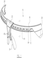
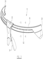
FIG. 1 is a front perspective view of an eyewear frame structure according to one embodiment; -
FIG. 2 is a partial rear perspective view of the frame structure ofFIG. 1 with a section thereof cut away along line 7-7 ofFIG 1 , showing a vent passage thereof; -
FIG. 3 is a front perspective view of a base frame of the frame structure ofFIG. 1 ; -
FIG. 4 is a front perspective view of a front frame of the frame structure ofFIG. 1 ; -
FIG. 5 is a cross-sectional view of the base frame taken along line 5-5 inFIG. 3 , showing a cross-section of the base frame between adjacent vent passages; -
FIG. 6 is a cross-sectional view of the base frame taken along 6-6 inFIG. 3 , showing front and back recesses in fluid communication with each other to provide structural features of the complete vent passage in the frame structure ofFIG. 1 ; -
FIG. 7 is a cross-sectional view of the frame structure taken along line 7-7 inFIG. 1 , showing the vent passage having a substantially horizontal section and a substantially vertical section; and -
FIG. 8 is a cross-sectional view of the base frame taken along line 8-8 inFIG. 6 , showing the back recess formed in the back side of the base frame. - It will be noted that throughout the appended drawings, like features are identified by like reference numerals.
- It should also be noted that throughout the following description and claims, the terms "front"/"forward" and "back"/"rearward"("rear") refer to directions from the perspective of the user - i.e. further away from the user's face is referred to as "front" or "forward" and closer to the user's face is referred to as "back" or "rear".
-
FIGS. 1 ,2 and7 illustrate aneyewear frame structure 10 according to one embodiment, for holding at least one lens (shown in broken lines inFIG. 2 ) thereto. Theeyewear frame structure 10 includes abase frame 12 which may be of a substantially rigid plastic material, afront frame 14 attached to a front side (not numbered) of thebase frame 12, and acomfort bar 16 attached to a back side of thebase frame 12. Thefront frame 14 andcomfort bar 16 may be made of a material that is flexible and soft relative to the rigid plastic material of thebase frame 12. Such flexible and soft material may for example, be rubber. Theframe structure 10 may be configured in a curvature suitable for being worn on a user's head. - Referring to
FIGS. 1-3 and5-8 , thebase frame 12 includes anupper member 18 extending betweenopposed ends 20 of thebase frame 12, which is configured with respective enlarged end sections (not numbered) for providing, for example, suitable pivotal connections to temples (not shown) of the eyewear. - Optionally, the
base frame 12 may include aconnector 22 attached to a central portion of theupper member 18. Theconnector 22 may extend downwardly to support a pair ofnose pieces 24 which are not part of the described subject matter and will not be further described hereinafter. Theupper member 18 may therefore be formed as two similar sections, extending from theconnector 22 toward the respective opposedends 20. Due to the similarity of the two sections and for simplicity of description, only one section will be described in detail hereinafter. - The
upper member 18 of thebase frame 12 defines a front side (not numbered) between atop surface 26 and abottom surface 28 thereof, facing away from a user's face. Theupper member 18 also defines a back side (not numbered) thereof between the top andbottom surfaces upper member 18 may include anupper ridge 30 and a lower ridge 32. Both upper andlower ridges 30, 32 project forwardly and extend along a length of theupper member 18 between theconnector 22 and the corresponding enlarged end section. Agroove 34 which may have a triangular cross-section, may therefore be formed between the upper andlower ridges 30 and 32, and extends along a length of theupper member 18, corresponding with theridges 30, 32. Thegroove 34 may therefore be formed with anupper surface 36 and alower surface 38 which in combination define the triangular cross-section of thegroove 34. - The back side of the
upper member 18 may include two substantially vertical surfaces (which are referred to as a first rear-facingsurface 40 and a second rear-facing surface 42) and a downward-facingsurface 44 which in combination define a shoulder (not numbered) extending along a length of theupper member 18 on the back side thereof. Incliningtransitional surfaces top surface 26 and the first rear-facingsurface 40 and between thebottom surface 28 and the second rear-facingsurface 42, respectively. The first rear-facingsurface 40 may define a vertical dimension from the incliningtransitional surface 46 to the downward-facingsurface 44 - The
upper member 18 may define a plurality of spaced apartfirst recesses 50 in the groove 34 (seeFIG. 6 ). Eachfirst recess 50 may define an opening 52 (seeFIGS. 3 and6 ) on theupper surface 36 of thegroove 34 and may be recessed rearwardly to define side surfaces (not numbered, seeFIG. 8 ) and an upper surface 54 (seeFIG. 6 ). Therefore, thefirst recess 50 may have a triangular cross-section as shown inFIG. 6 . - The
upper member 18 may further define a plurality ofsecond recesses 56 on the back side thereof. Eachsecond recess 56 may define anopening 58 on the first rear-facingsurface 40 and may be recessed forwardly to define side surfaces (not numbered, seeFIG. 8 ) and aninner surface 60. Thesecond recess 56 may be configured to have a vertical dimension corresponding to the vertical dimension of the first rear-facingsurface 40, resulting in formation of anotheropening 62 of thesecond recess 56 in the downward-facingsurface 44. - The first recesses 50 may align with and be in fluid communication with respective second recesses 56. Therefore, a part of the
inner surface 60 of the second recess 56 (as shown by broken lines inFIG. 6 ) may not exist and eachfirst recess 50 and the correspondingsecond recess 56 in combination may form a passageway extending through theupper member 18 of thebase frame 12 between the front and back sides thereof. - Referring to
FIGS. 1-2 ,4 and7 , thefront frame 14 includes anelongate member 64. Optionally, theelongate member 64 may have symmetrical right and left sections (not numbered) joined together by acenter piece 65 which may be configured to correspond with and be attached to theconnector 22 of thebase frame 12. - Each section of the
elongate member 64 may include aflat strap 66 and a plurality ofspacers 68 projecting upwardly from theflat strap 66 to define a plurality ofrecesses 70 betweenadjacent spacers 68. An upward-facing surface of the flat strap may form abottom surface 72 of eachrecess 70. Each section of theelongate member 64 of thefront frame 14 is partially received in thegroove 34, which may be triangular, defined in the front side of thebase frame 12. - Each
spacer 68 of theelongate member 64 may define a triangular cross-section including a front-facingsurface 74 and rear-facingsurface 76. The triangular cross-section of thespacer 68 may be configured such that the rear-facingsurface 76 is in full contact with theupper surface 36 of thetriangular groove 34 of thebase frame 12. The plurality ofrecesses 70 defined betweenadjacent spacers 68 according to one embodiment, may align with the respective openings 52 (seeFIG. 3 ) defined in theupper surface 36 of thetriangular groove 34 in thebase frame 12. Therefore, a plurality of substantially horizontal passage sections (not numbered) may be formed, each having a top surface defined by theupper surface 54 of the respective recess 50 (seeFIGS. 6 and7 ) in thebase frame 12 and a bottom surface defined by thebottom surface 72 of therespective recess 70 of theflat strap 66 in thefront frame 14. It should be noted that the substantially horizontal passage section defined between theupper surface 54 of therecess 50 and thebottom surface 72 of therecess 70, is in fluid communication with the second recess 56 (seeFIG. 6 ) defined in the back side of theupper member 18 of thebase frame 12. - The
comfort bar 16 according to one embodiment is attached to the back side of theupper member 18 of thebase frame 12, having a length extending between and terminating at the two opposed enlarged end sections of theupper member 18. Optionally, thecomfort bar 16 may comprise two sections corresponding to the respective sections of theelongate member 64 of thefront frame 14. - The
comfort bar 16 may be configured such that afront surface 78 of thecomfort bar 16 is placed flat against the first rear-facingsurface 40 of theupper member 18 of thebase frame 12, and atop surface 80 of thecomfort bar 16 is in full contact with the incliningtransition surface 46 of theupper member 18. Therefore, thecomfort bar 16 may partially cover the openings of the respective second recesses 56 (seeFIGS. 6 and7 ) that is, thecomfort bar 16 only coversopenings 58 of each recess 56 (defined in on the first rear facing surface 40), but does not block theopening 62 of therecesses 56 defined on the downward-facingsurface 44 of theupper member 18. Therefore, eachsecond recess 56 with theopening 62 may form a substantially vertical passage section (not numbered) between theinner surface 60 of therecess 56 in thebase frame 12 and thefront surface 78 of thecomfort bar 16. The substantially horizontal passage section formed by the combination of therecesses recess 56 are in fluid communication and therefore, in combination form an "indirect" or L-shaped vent passage (not numbered) extending through theframe structure 10. The "indirect" OR L-shaped vent passage therefore has an opening thereof on the front side of theframe structure 10 and an opening on the back side of theframe structure 10. Therefore, the "indirect" or L-shaped vent passage allows effective moisture venting and air circulation while preventing foreign particles which pass through the vent passages from entering the user's eyes and from impacting the user's face. - Referring to
FIGS. 2 and7 , theelongate member 64 of thefront frame 14 may be partially received in thetriangular groove 34 in theupper member 18 of thebase frame 12 such that thegroove 34 is not fully filled by theelongate member 64. Therefore, a smaller triangular groove (not numbered) may be formed between a downward-facing surface 81 (the bottom) of theflat strap 66 of theelongate member 64 and thelower surface 38 of thetriangular groove 34 in theupper member 18 of thebase frame 12. This smaller triangular groove may form a retaining device for retaining an upper peripheral edge of the lens, such as illustrated inFIG. 2 . Theframe structure 10 may be provided with further retaining means for retaining the lens or lenses to be attached thereto according to the configuration of the one more lenses. However, this feature is not part of the described subject matter and will not be further described herein. - The above description is meant to be exemplary only, and one skilled in the art will recognize that changes may be made to the embodiments described without departing from the scope of the appended claims. For example, the base frame and front frame may not have the respective connector and central member such that the grooves in the base frame and the elongate member of the front frame may not be divided into sections. The base frame may be configured to have front and back sides different from the above-described embodiments but may provide a suitable interface with respect to the front frame and comfort bar to form the vent passages defined therebetween. Modifications which fall within the scope of the appended claims will be apparent to those skilled in the art, in light of a review of this disclosure.
Claims (13)
- An eyewear frame structure (10) for holding at least one lens thereto, the eyewear frame structure (10) comprising:a base frame (12) including an upper member (18) extending between opposed ends (20) of the base frame (12), the opposed ends (20) configured with respective enlarged end sections for providing pivotal connections to temples of the eyewear frame structure (10), and defining a groove (34) in a front side of the upper member (18) thereof, the groove (34) extending along a length of the upper member (18);a front frame (14) molded to the front side of the upper member of the base frame (12) and thereby attached thereto, the front frame (14) including an elongate member (64) attached to a front side of the upper member (18) of the base frame (12), the elongate member (64) of the front frame (14) being partially received in the groove (34) of the base frame (12);a comfort bar (16) molded to the base frame (12) and thereby attached thereto, the comfort bar (16) disposed on a back side of the upper member (18) of the base frame (12); anda plurality of vent passages extending through the frame structure (10), each of the vent passages including a substantially horizontal section defined between the base frame (12) and the front frame (14) and a substantially vertical section defined between the base frame (12) and the comfort bar (16), wherein the substantially horizontal section of the vent passage comprises a top surface defined on the base frame (12) and a bottom surface defined on the front frame (14), and wherein the substantially vertical section of the vent passage comprises a front surface thereof defined on the base frame (12) and a rear surface defined on the comfort bar (16).
- The eyewear frame structure (10) as defined in claim 1, wherein the elongate member (64) of the front frame (14) comprises a plurality of spacers (68) projecting upwardly from the elongate member (64) to define a plurality of recesses (70) between adjacent spacers (68), each of the recesses (70) having a bottom defining a bottom surface (72) of the substantially horizontal section of the vent passage.
- The eyewear frame structure (10) as defined in claim 2 wherein the groove (34) in the upper member (18) of the base frame (12) comprises a triangular cross section defining an upper surface (36) and a lower surface (38) of the groove (34), and wherein each of the spacers (68) of the front frame (14) comprises a triangular cross section defining a front-facing surface (74) and a rear-facing surface (76), the rear-facing surface (76) being in contact with the upper surface of the groove (34).
- The eyewear frame structure (10) as defined in any one of claims 1 to 3, wherein the comfort bar (16) extends between and terminates at two opposed end sections of the base frame (12).
- The eyewear frame structure (10) as defined in any one of claims 1 to 4, wherein the upper member (18) of the base frame (12) defines a plurality of first recesses (50) in the groove (34), each of the first recesses (50) being recessed rearwardly to define an opening (52) on the upper surface (36) of the groove (34) and having an upper surface (54), the upper surface (36) defining a top surface of a substantially horizontal section of each of said vent passages.
- The eyewear frame structure (10) as defined in claim 5, wherein the upper member (18) of the base frame (12) defines a plurality of second recesses (56) on the back side thereof, each of the second recesses (56) being recessed forwardly to define an inner surface and an opening on respective rear-facing and downward-facing surfaces (40, 44) of the upper member (18) of the base frame (12), the second recesses (56) being in communication with the respective first recesses (50), the inner surface of the second recess (56) defining a front surface of a substantially vertical section of each of said vent passages.
- The eyewear frame structure (10) as defined in claim 6, wherein the comfort bar (16) covers the openings of the respective second recesses (56) defined on the rear-facing surface (40), the openings of the second recesses (56) defined on the downward-facing surface (44) forming an opening of the substantially vertical section of the respective vent passages, a front surface of the comfort bar (16) defining a rear surface of the substantially vertical section of each vent passage.
- The eyewear frame structure (10) as defined in any one of claims 1 to 7, wherein the elongate member (64) of the front frame (14) and the upper member (18) of the base frame (12) in combination define a groove therebetween, the groove extending along a length of the frame structure (10) for receiving a section of an upper edge of the at least one lens.
- The eyewear (10) as defined in any one of claims 1 to 8, wherein the front frame (14) and the comfort bar (16) are flexible and soft relative to the base frame (12).
- A method for making the eyewear frame structure (10) according to any preceding claim, comprising steps of:a) molding the base frame (12) structure; andb) with the presence of the molded base frame (12), molding the front frame (14) to the front side of the upper member (18) of the base frame (12) and molding the comfort bar (16) attached to the back side of the upper member (18) of the base frame (12).
- The method as defined in claim 10, wherein molding the base frame (12) structure includes using a molding material which is rigid when cured, and wherein the front frame (14) and the comfort bar (16) are molded using a respective molding material which is flexible and soft relative to the rigid material of the base frame (12).
- The method as defined in claim 11, wherein the front frame (14) and the comfort bar (16) are molded in one molding procedure using a same molding material.
- The method as defined in claim 11, wherein the front frame (14) and the comfort bar (16) are molded in separate molding procedures using different molding materials.
Applications Claiming Priority (2)
| Application Number | Priority Date | Filing Date | Title |
|---|---|---|---|
| US14/638,347 US9658474B2 (en) | 2015-03-04 | 2015-03-04 | Eyewear frame having vents |
| PCT/US2016/019537 WO2016140854A1 (en) | 2015-03-04 | 2016-02-25 | Eyewear frame having vents |
Publications (2)
| Publication Number | Publication Date |
|---|---|
| EP3265869A1 EP3265869A1 (en) | 2018-01-10 |
| EP3265869B1 true EP3265869B1 (en) | 2024-09-25 |
Family
ID=55524450
Family Applications (1)
| Application Number | Title | Priority Date | Filing Date |
|---|---|---|---|
| EP16709634.6A Active EP3265869B1 (en) | 2015-03-04 | 2016-02-25 | Eyewear frame having vents |
Country Status (5)
| Country | Link |
|---|---|
| US (1) | US9658474B2 (en) |
| EP (1) | EP3265869B1 (en) |
| AU (1) | AU2016226531B2 (en) |
| BR (1) | BR112017018930B1 (en) |
| WO (1) | WO2016140854A1 (en) |
Families Citing this family (8)
| Publication number | Priority date | Publication date | Assignee | Title |
|---|---|---|---|---|
| CN107193136A (en) * | 2017-06-20 | 2017-09-22 | 北京工业大学 | The antifog skiing goggle of 3D printing wall attachment effect inner flow passage formula |
| USD865854S1 (en) * | 2018-01-25 | 2019-11-05 | Brent Sheldon | Eyewear |
| USD925645S1 (en) * | 2019-07-12 | 2021-07-20 | Brent Sheldon | Eyewear |
| US11428765B2 (en) * | 2019-11-05 | 2022-08-30 | Quality Electrodynamics, Llc | MRI head coil comprising an open shield |
| TWI770643B (en) * | 2019-11-05 | 2022-07-11 | 布蘭特 雪爾登 | Eyewear having multidirectional venting |
| USD934332S1 (en) | 2019-12-20 | 2021-10-26 | Brent Sheldon | Eyewear |
| US11353718B2 (en) * | 2020-02-07 | 2022-06-07 | Hsien Chang Optical Industrial Co., Ltd. | Eyeglasses structure |
| US11526015B2 (en) * | 2020-02-21 | 2022-12-13 | Meta Platforms Technologies, Llc | Facial interfaces for head-mounted displays and related systems and methods |
Family Cites Families (13)
| Publication number | Priority date | Publication date | Assignee | Title |
|---|---|---|---|---|
| US5239320A (en) | 1989-11-22 | 1993-08-24 | Corning Incorporated | Venting system for eyeglasses |
| US5576775A (en) | 1995-06-09 | 1996-11-19 | Etablissements Bolle S.N.C. | Eyeglasses with controlled ventilation frame and lens |
| US5638145A (en) | 1996-02-29 | 1997-06-10 | Oakley, Inc. | Vented eyeglass lens |
| US5815235A (en) | 1997-07-09 | 1998-09-29 | John L. Runckel Trust | Ski goggles with pivotal frame members for interchanging lenses |
| US6550914B1 (en) | 2001-10-26 | 2003-04-22 | Pan-Optx, Inc. | Eyewear with filtered ventilation |
| US7267434B2 (en) * | 2004-03-23 | 2007-09-11 | Dioptics Medical Products, Inc. | Eyeglasses and method of manufacture thereof |
| US6959988B1 (en) | 2004-08-04 | 2005-11-01 | Brent Sheldon | Eyewear having detachable lens retaining member |
| US7325919B2 (en) | 2005-12-13 | 2008-02-05 | Neville Sheldon | Eyewear having lens retaining member |
| US8303109B2 (en) | 2006-11-30 | 2012-11-06 | Pasquale Matera | Eyewear device and method of making the same |
| TWM377603U (en) * | 2009-11-26 | 2010-04-01 | All Logic Internat Co Ltd | Assembling stabilized eyeglasses |
| US8047649B2 (en) | 2010-01-14 | 2011-11-01 | Chih-Ming Chen | Eyeglasses |
| US8348420B2 (en) | 2010-11-23 | 2013-01-08 | High Rainbow Enterprise Co., Ltd. | Eyeglass with a soft sleeving element |
| US8366267B2 (en) | 2011-01-04 | 2013-02-05 | T-Link Ppe Ltd. | Spectacle structure |
-
2015
- 2015-03-04 US US14/638,347 patent/US9658474B2/en active Active
-
2016
- 2016-02-25 WO PCT/US2016/019537 patent/WO2016140854A1/en not_active Ceased
- 2016-02-25 BR BR112017018930-5A patent/BR112017018930B1/en not_active IP Right Cessation
- 2016-02-25 AU AU2016226531A patent/AU2016226531B2/en active Active
- 2016-02-25 EP EP16709634.6A patent/EP3265869B1/en active Active
Also Published As
| Publication number | Publication date |
|---|---|
| US9658474B2 (en) | 2017-05-23 |
| AU2016226531B2 (en) | 2021-04-01 |
| BR112017018930A2 (en) | 2018-05-15 |
| BR112017018930B1 (en) | 2022-08-02 |
| US20160259184A1 (en) | 2016-09-08 |
| EP3265869A1 (en) | 2018-01-10 |
| AU2016226531A1 (en) | 2017-10-26 |
| WO2016140854A1 (en) | 2016-09-09 |
Similar Documents
| Publication | Publication Date | Title |
|---|---|---|
| US9658474B2 (en) | Eyewear frame having vents | |
| US6783235B1 (en) | Fog-free protective glasses | |
| US11020276B1 (en) | Protective eyewear | |
| US12228626B2 (en) | Eyewear having multidirectional venting | |
| CN103476282B (en) | Helmets for Recreational Sports | |
| EP1156357A1 (en) | Eye covering | |
| US20040263773A1 (en) | Light-blocking air vents for eyewear | |
| CN111743258B (en) | Helmet assembly and method with eyeglass and air deflector system | |
| US8919952B2 (en) | Eyeglass temple having an auxiliary cushion frame | |
| US20120169989A1 (en) | Spectacle structure | |
| KR200367353Y1 (en) | Glasses having multi-purpose | |
| US20130097768A1 (en) | Ventilated goggles | |
| US10067360B2 (en) | Eyeglass frames with dynamic vent | |
| US20080120767A1 (en) | Face-piece for diving goggles | |
| JP6940964B2 (en) | Mask equipment | |
| CN114902122B (en) | Glasses with multidirectional ventilation | |
| US20150362758A1 (en) | Ventilation structure of eyeglasses | |
| KR101554902B1 (en) | Helmet for Leisure Sports | |
| US20190094572A1 (en) | Heat dissipation structure of a pair of glasses | |
| TWM449969U (en) | Glasses frame structure with cushioning function | |
| CN206906711U (en) | Antifogging light-filtering frameless snow goggles | |
| JP3188924U (en) | Double-wearing protective glasses | |
| JP2021167856A (en) | Protective goggles | |
| JP3184321U (en) | Hooded eyeglass frame | |
| JP2023073941A (en) | Anti-fogging apparatus for glasses |
Legal Events
| Date | Code | Title | Description |
|---|---|---|---|
| STAA | Information on the status of an ep patent application or granted ep patent |
Free format text: STATUS: THE INTERNATIONAL PUBLICATION HAS BEEN MADE |
|
| PUAI | Public reference made under article 153(3) epc to a published international application that has entered the european phase |
Free format text: ORIGINAL CODE: 0009012 |
|
| STAA | Information on the status of an ep patent application or granted ep patent |
Free format text: STATUS: REQUEST FOR EXAMINATION WAS MADE |
|
| 17P | Request for examination filed |
Effective date: 20171004 |
|
| AK | Designated contracting states |
Kind code of ref document: A1 Designated state(s): AL AT BE BG CH CY CZ DE DK EE ES FI FR GB GR HR HU IE IS IT LI LT LU LV MC MK MT NL NO PL PT RO RS SE SI SK SM TR |
|
| AX | Request for extension of the european patent |
Extension state: BA ME |
|
| DAV | Request for validation of the european patent (deleted) | ||
| DAX | Request for extension of the european patent (deleted) | ||
| STAA | Information on the status of an ep patent application or granted ep patent |
Free format text: STATUS: EXAMINATION IS IN PROGRESS |
|
| 17Q | First examination report despatched |
Effective date: 20210805 |
|
| GRAP | Despatch of communication of intention to grant a patent |
Free format text: ORIGINAL CODE: EPIDOSNIGR1 |
|
| STAA | Information on the status of an ep patent application or granted ep patent |
Free format text: STATUS: GRANT OF PATENT IS INTENDED |
|
| INTG | Intention to grant announced |
Effective date: 20240503 |
|
| GRAS | Grant fee paid |
Free format text: ORIGINAL CODE: EPIDOSNIGR3 |
|
| GRAA | (expected) grant |
Free format text: ORIGINAL CODE: 0009210 |
|
| STAA | Information on the status of an ep patent application or granted ep patent |
Free format text: STATUS: THE PATENT HAS BEEN GRANTED |
|
| AK | Designated contracting states |
Kind code of ref document: B1 Designated state(s): AL AT BE BG CH CY CZ DE DK EE ES FI FR GB GR HR HU IE IS IT LI LT LU LV MC MK MT NL NO PL PT RO RS SE SI SK SM TR |
|
| REG | Reference to a national code |
Ref country code: GB Ref legal event code: FG4D |
|
| REG | Reference to a national code |
Ref country code: CH Ref legal event code: EP |
|
| REG | Reference to a national code |
Ref country code: DE Ref legal event code: R096 Ref document number: 602016089528 Country of ref document: DE |
|
| REG | Reference to a national code |
Ref country code: IE Ref legal event code: FG4D |
|
| REG | Reference to a national code |
Ref country code: LT Ref legal event code: MG9D |
|
| PG25 | Lapsed in a contracting state [announced via postgrant information from national office to epo] |
Ref country code: NO Free format text: LAPSE BECAUSE OF FAILURE TO SUBMIT A TRANSLATION OF THE DESCRIPTION OR TO PAY THE FEE WITHIN THE PRESCRIBED TIME-LIMIT Effective date: 20241225 |
|
| PG25 | Lapsed in a contracting state [announced via postgrant information from national office to epo] |
Ref country code: GR Free format text: LAPSE BECAUSE OF FAILURE TO SUBMIT A TRANSLATION OF THE DESCRIPTION OR TO PAY THE FEE WITHIN THE PRESCRIBED TIME-LIMIT Effective date: 20241226 Ref country code: FI Free format text: LAPSE BECAUSE OF FAILURE TO SUBMIT A TRANSLATION OF THE DESCRIPTION OR TO PAY THE FEE WITHIN THE PRESCRIBED TIME-LIMIT Effective date: 20240925 |
|
| PG25 | Lapsed in a contracting state [announced via postgrant information from national office to epo] |
Ref country code: BG Free format text: LAPSE BECAUSE OF FAILURE TO SUBMIT A TRANSLATION OF THE DESCRIPTION OR TO PAY THE FEE WITHIN THE PRESCRIBED TIME-LIMIT Effective date: 20240925 |
|
| PG25 | Lapsed in a contracting state [announced via postgrant information from national office to epo] |
Ref country code: LV Free format text: LAPSE BECAUSE OF FAILURE TO SUBMIT A TRANSLATION OF THE DESCRIPTION OR TO PAY THE FEE WITHIN THE PRESCRIBED TIME-LIMIT Effective date: 20240925 |
|
| PG25 | Lapsed in a contracting state [announced via postgrant information from national office to epo] |
Ref country code: RS Free format text: LAPSE BECAUSE OF FAILURE TO SUBMIT A TRANSLATION OF THE DESCRIPTION OR TO PAY THE FEE WITHIN THE PRESCRIBED TIME-LIMIT Effective date: 20241225 |
|
| REG | Reference to a national code |
Ref country code: NL Ref legal event code: MP Effective date: 20240925 |
|
| PG25 | Lapsed in a contracting state [announced via postgrant information from national office to epo] |
Ref country code: RS Free format text: LAPSE BECAUSE OF FAILURE TO SUBMIT A TRANSLATION OF THE DESCRIPTION OR TO PAY THE FEE WITHIN THE PRESCRIBED TIME-LIMIT Effective date: 20241225 Ref country code: NO Free format text: LAPSE BECAUSE OF FAILURE TO SUBMIT A TRANSLATION OF THE DESCRIPTION OR TO PAY THE FEE WITHIN THE PRESCRIBED TIME-LIMIT Effective date: 20241225 Ref country code: LV Free format text: LAPSE BECAUSE OF FAILURE TO SUBMIT A TRANSLATION OF THE DESCRIPTION OR TO PAY THE FEE WITHIN THE PRESCRIBED TIME-LIMIT Effective date: 20240925 Ref country code: GR Free format text: LAPSE BECAUSE OF FAILURE TO SUBMIT A TRANSLATION OF THE DESCRIPTION OR TO PAY THE FEE WITHIN THE PRESCRIBED TIME-LIMIT Effective date: 20241226 Ref country code: FI Free format text: LAPSE BECAUSE OF FAILURE TO SUBMIT A TRANSLATION OF THE DESCRIPTION OR TO PAY THE FEE WITHIN THE PRESCRIBED TIME-LIMIT Effective date: 20240925 Ref country code: BG Free format text: LAPSE BECAUSE OF FAILURE TO SUBMIT A TRANSLATION OF THE DESCRIPTION OR TO PAY THE FEE WITHIN THE PRESCRIBED TIME-LIMIT Effective date: 20240925 |
|
| REG | Reference to a national code |
Ref country code: AT Ref legal event code: MK05 Ref document number: 1727136 Country of ref document: AT Kind code of ref document: T Effective date: 20240925 |
|
| PG25 | Lapsed in a contracting state [announced via postgrant information from national office to epo] |
Ref country code: NL Free format text: LAPSE BECAUSE OF FAILURE TO SUBMIT A TRANSLATION OF THE DESCRIPTION OR TO PAY THE FEE WITHIN THE PRESCRIBED TIME-LIMIT Effective date: 20240925 |
|
| PG25 | Lapsed in a contracting state [announced via postgrant information from national office to epo] |
Ref country code: IS Free format text: LAPSE BECAUSE OF FAILURE TO SUBMIT A TRANSLATION OF THE DESCRIPTION OR TO PAY THE FEE WITHIN THE PRESCRIBED TIME-LIMIT Effective date: 20250125 Ref country code: PT Free format text: LAPSE BECAUSE OF FAILURE TO SUBMIT A TRANSLATION OF THE DESCRIPTION OR TO PAY THE FEE WITHIN THE PRESCRIBED TIME-LIMIT Effective date: 20250127 |
|
| PG25 | Lapsed in a contracting state [announced via postgrant information from national office to epo] |
Ref country code: RO Free format text: LAPSE BECAUSE OF FAILURE TO SUBMIT A TRANSLATION OF THE DESCRIPTION OR TO PAY THE FEE WITHIN THE PRESCRIBED TIME-LIMIT Effective date: 20240925 Ref country code: SM Free format text: LAPSE BECAUSE OF FAILURE TO SUBMIT A TRANSLATION OF THE DESCRIPTION OR TO PAY THE FEE WITHIN THE PRESCRIBED TIME-LIMIT Effective date: 20240925 |
|
| PG25 | Lapsed in a contracting state [announced via postgrant information from national office to epo] |
Ref country code: ES Free format text: LAPSE BECAUSE OF FAILURE TO SUBMIT A TRANSLATION OF THE DESCRIPTION OR TO PAY THE FEE WITHIN THE PRESCRIBED TIME-LIMIT Effective date: 20240925 |
|
| PG25 | Lapsed in a contracting state [announced via postgrant information from national office to epo] |
Ref country code: EE Free format text: LAPSE BECAUSE OF FAILURE TO SUBMIT A TRANSLATION OF THE DESCRIPTION OR TO PAY THE FEE WITHIN THE PRESCRIBED TIME-LIMIT Effective date: 20240925 Ref country code: AT Free format text: LAPSE BECAUSE OF FAILURE TO SUBMIT A TRANSLATION OF THE DESCRIPTION OR TO PAY THE FEE WITHIN THE PRESCRIBED TIME-LIMIT Effective date: 20240925 |
|
| PG25 | Lapsed in a contracting state [announced via postgrant information from national office to epo] |
Ref country code: PL Free format text: LAPSE BECAUSE OF FAILURE TO SUBMIT A TRANSLATION OF THE DESCRIPTION OR TO PAY THE FEE WITHIN THE PRESCRIBED TIME-LIMIT Effective date: 20240925 Ref country code: CZ Free format text: LAPSE BECAUSE OF FAILURE TO SUBMIT A TRANSLATION OF THE DESCRIPTION OR TO PAY THE FEE WITHIN THE PRESCRIBED TIME-LIMIT Effective date: 20240925 |
|
| PG25 | Lapsed in a contracting state [announced via postgrant information from national office to epo] |
Ref country code: IT Free format text: LAPSE BECAUSE OF FAILURE TO SUBMIT A TRANSLATION OF THE DESCRIPTION OR TO PAY THE FEE WITHIN THE PRESCRIBED TIME-LIMIT Effective date: 20240925 Ref country code: SK Free format text: LAPSE BECAUSE OF FAILURE TO SUBMIT A TRANSLATION OF THE DESCRIPTION OR TO PAY THE FEE WITHIN THE PRESCRIBED TIME-LIMIT Effective date: 20240925 |
|
| REG | Reference to a national code |
Ref country code: DE Ref legal event code: R097 Ref document number: 602016089528 Country of ref document: DE |
|
| PG25 | Lapsed in a contracting state [announced via postgrant information from national office to epo] |
Ref country code: DK Free format text: LAPSE BECAUSE OF FAILURE TO SUBMIT A TRANSLATION OF THE DESCRIPTION OR TO PAY THE FEE WITHIN THE PRESCRIBED TIME-LIMIT Effective date: 20240925 |
|
| PLBE | No opposition filed within time limit |
Free format text: ORIGINAL CODE: 0009261 |
|
| STAA | Information on the status of an ep patent application or granted ep patent |
Free format text: STATUS: NO OPPOSITION FILED WITHIN TIME LIMIT |
|
| 26N | No opposition filed |
Effective date: 20250626 |
|
| PG25 | Lapsed in a contracting state [announced via postgrant information from national office to epo] |
Ref country code: SE Free format text: LAPSE BECAUSE OF FAILURE TO SUBMIT A TRANSLATION OF THE DESCRIPTION OR TO PAY THE FEE WITHIN THE PRESCRIBED TIME-LIMIT Effective date: 20240925 |
|
| PG25 | Lapsed in a contracting state [announced via postgrant information from national office to epo] |
Ref country code: MC Free format text: LAPSE BECAUSE OF FAILURE TO SUBMIT A TRANSLATION OF THE DESCRIPTION OR TO PAY THE FEE WITHIN THE PRESCRIBED TIME-LIMIT Effective date: 20240925 |
|
| REG | Reference to a national code |
Ref country code: CH Ref legal event code: PL |
|
| PG25 | Lapsed in a contracting state [announced via postgrant information from national office to epo] |
Ref country code: LU Free format text: LAPSE BECAUSE OF NON-PAYMENT OF DUE FEES Effective date: 20250225 |
|
| PG25 | Lapsed in a contracting state [announced via postgrant information from national office to epo] |
Ref country code: CH Free format text: LAPSE BECAUSE OF NON-PAYMENT OF DUE FEES Effective date: 20250228 |
|
| REG | Reference to a national code |
Ref country code: BE Ref legal event code: MM Effective date: 20250228 |
|
| PG25 | Lapsed in a contracting state [announced via postgrant information from national office to epo] |
Ref country code: HR Free format text: LAPSE BECAUSE OF FAILURE TO SUBMIT A TRANSLATION OF THE DESCRIPTION OR TO PAY THE FEE WITHIN THE PRESCRIBED TIME-LIMIT Effective date: 20240925 |
|
| PG25 | Lapsed in a contracting state [announced via postgrant information from national office to epo] |
Ref country code: BE Free format text: LAPSE BECAUSE OF NON-PAYMENT OF DUE FEES Effective date: 20250228 |
|
| PG25 | Lapsed in a contracting state [announced via postgrant information from national office to epo] |
Ref country code: IE Free format text: LAPSE BECAUSE OF NON-PAYMENT OF DUE FEES Effective date: 20250225 |
|
| PGFP | Annual fee paid to national office [announced via postgrant information from national office to epo] |
Ref country code: GB Payment date: 20260216 Year of fee payment: 11 |
|
| PGFP | Annual fee paid to national office [announced via postgrant information from national office to epo] |
Ref country code: DE Payment date: 20260218 Year of fee payment: 11 |
|
| PGFP | Annual fee paid to national office [announced via postgrant information from national office to epo] |
Ref country code: FR Payment date: 20260223 Year of fee payment: 11 |
|
| PG25 | Lapsed in a contracting state [announced via postgrant information from national office to epo] |
Ref country code: CY Free format text: LAPSE BECAUSE OF FAILURE TO SUBMIT A TRANSLATION OF THE DESCRIPTION OR TO PAY THE FEE WITHIN THE PRESCRIBED TIME-LIMIT Effective date: 20240925 |
|
| PG25 | Lapsed in a contracting state [announced via postgrant information from national office to epo] |
Ref country code: LT Free format text: LAPSE BECAUSE OF FAILURE TO SUBMIT A TRANSLATION OF THE DESCRIPTION OR TO PAY THE FEE WITHIN THE PRESCRIBED TIME-LIMIT Effective date: 20240925 |
|
| PG25 | Lapsed in a contracting state [announced via postgrant information from national office to epo] |
Ref country code: TR Free format text: LAPSE BECAUSE OF FAILURE TO SUBMIT A TRANSLATION OF THE DESCRIPTION OR TO PAY THE FEE WITHIN THE PRESCRIBED TIME-LIMIT Effective date: 20240925 |