EP3265237B1 - Spray gun with high transfer efficiency and method for use thereof - Google Patents
Spray gun with high transfer efficiency and method for use thereof Download PDFInfo
- Publication number
- EP3265237B1 EP3265237B1 EP15710692.3A EP15710692A EP3265237B1 EP 3265237 B1 EP3265237 B1 EP 3265237B1 EP 15710692 A EP15710692 A EP 15710692A EP 3265237 B1 EP3265237 B1 EP 3265237B1
- Authority
- EP
- European Patent Office
- Prior art keywords
- air
- coating composition
- fluid
- spray gun
- fan
- Prior art date
- Legal status (The legal status is an assumption and is not a legal conclusion. Google has not performed a legal analysis and makes no representation as to the accuracy of the status listed.)
- Active
Links
- 239000007921 spray Substances 0.000 title claims description 206
- 238000000034 method Methods 0.000 title claims description 16
- 239000012530 fluid Substances 0.000 claims description 132
- 239000008199 coating composition Substances 0.000 claims description 86
- 238000000889 atomisation Methods 0.000 claims description 55
- 238000009826 distribution Methods 0.000 claims description 43
- 239000007788 liquid Substances 0.000 claims description 40
- 238000005507 spraying Methods 0.000 claims description 18
- 239000000758 substrate Substances 0.000 claims description 18
- 230000001105 regulatory effect Effects 0.000 claims description 13
- 239000003973 paint Substances 0.000 description 28
- 239000011248 coating agent Substances 0.000 description 21
- 238000000576 coating method Methods 0.000 description 21
- XLYOFNOQVPJJNP-UHFFFAOYSA-N water Substances O XLYOFNOQVPJJNP-UHFFFAOYSA-N 0.000 description 16
- 239000011247 coating layer Substances 0.000 description 11
- 239000010410 layer Substances 0.000 description 8
- 230000007246 mechanism Effects 0.000 description 5
- 239000011230 binding agent Substances 0.000 description 4
- 238000001723 curing Methods 0.000 description 4
- 239000000203 mixture Substances 0.000 description 4
- 239000003960 organic solvent Substances 0.000 description 4
- 239000004971 Cross linker Substances 0.000 description 3
- 150000001875 compounds Chemical class 0.000 description 3
- 239000000049 pigment Substances 0.000 description 3
- 229920001228 polyisocyanate Polymers 0.000 description 3
- 239000005056 polyisocyanate Substances 0.000 description 3
- 230000005855 radiation Effects 0.000 description 3
- XEEYBQQBJWHFJM-UHFFFAOYSA-N Iron Chemical compound [Fe] XEEYBQQBJWHFJM-UHFFFAOYSA-N 0.000 description 2
- 239000002253 acid Substances 0.000 description 2
- NIXOWILDQLNWCW-UHFFFAOYSA-N acrylic acid group Chemical group C(C=C)(=O)O NIXOWILDQLNWCW-UHFFFAOYSA-N 0.000 description 2
- 239000000654 additive Substances 0.000 description 2
- 239000003795 chemical substances by application Substances 0.000 description 2
- 238000004132 cross linking Methods 0.000 description 2
- 239000007789 gas Substances 0.000 description 2
- 230000005484 gravity Effects 0.000 description 2
- 239000012948 isocyanate Substances 0.000 description 2
- IQPQWNKOIGAROB-UHFFFAOYSA-N isocyanate group Chemical group [N-]=C=O IQPQWNKOIGAROB-UHFFFAOYSA-N 0.000 description 2
- 150000002513 isocyanates Chemical class 0.000 description 2
- 239000004611 light stabiliser Substances 0.000 description 2
- 229910052751 metal Inorganic materials 0.000 description 2
- 239000002184 metal Substances 0.000 description 2
- 239000004033 plastic Substances 0.000 description 2
- 229920003023 plastic Polymers 0.000 description 2
- 239000004814 polyurethane Substances 0.000 description 2
- 229920002635 polyurethane Polymers 0.000 description 2
- 239000002987 primer (paints) Substances 0.000 description 2
- 238000007493 shaping process Methods 0.000 description 2
- 239000002904 solvent Substances 0.000 description 2
- 239000000126 substance Substances 0.000 description 2
- 208000019300 CLIPPERS Diseases 0.000 description 1
- UFHFLCQGNIYNRP-UHFFFAOYSA-N Hydrogen Chemical compound [H][H] UFHFLCQGNIYNRP-UHFFFAOYSA-N 0.000 description 1
- FYYHWMGAXLPEAU-UHFFFAOYSA-N Magnesium Chemical compound [Mg] FYYHWMGAXLPEAU-UHFFFAOYSA-N 0.000 description 1
- XUIMIQQOPSSXEZ-UHFFFAOYSA-N Silicon Chemical compound [Si] XUIMIQQOPSSXEZ-UHFFFAOYSA-N 0.000 description 1
- HCHKCACWOHOZIP-UHFFFAOYSA-N Zinc Chemical compound [Zn] HCHKCACWOHOZIP-UHFFFAOYSA-N 0.000 description 1
- 239000000956 alloy Substances 0.000 description 1
- 229910045601 alloy Inorganic materials 0.000 description 1
- 239000004411 aluminium Substances 0.000 description 1
- 229910052782 aluminium Inorganic materials 0.000 description 1
- XAGFODPZIPBFFR-UHFFFAOYSA-N aluminium Chemical compound [Al] XAGFODPZIPBFFR-UHFFFAOYSA-N 0.000 description 1
- 150000001412 amines Chemical class 0.000 description 1
- 239000002518 antifoaming agent Substances 0.000 description 1
- 230000000712 assembly Effects 0.000 description 1
- 238000000429 assembly Methods 0.000 description 1
- QRUDEWIWKLJBPS-UHFFFAOYSA-N benzotriazole Chemical class C1=CC=C2N[N][N]C2=C1 QRUDEWIWKLJBPS-UHFFFAOYSA-N 0.000 description 1
- 230000015572 biosynthetic process Effects 0.000 description 1
- 239000000969 carrier Substances 0.000 description 1
- 208000021930 chronic lymphocytic inflammation with pontine perivascular enhancement responsive to steroids Diseases 0.000 description 1
- 230000001276 controlling effect Effects 0.000 description 1
- 238000001035 drying Methods 0.000 description 1
- 230000009977 dual effect Effects 0.000 description 1
- 230000000694 effects Effects 0.000 description 1
- 239000000945 filler Substances 0.000 description 1
- -1 for example Substances 0.000 description 1
- 125000000524 functional group Chemical group 0.000 description 1
- 229920001519 homopolymer Polymers 0.000 description 1
- 239000001257 hydrogen Substances 0.000 description 1
- 229910052739 hydrogen Inorganic materials 0.000 description 1
- 238000010348 incorporation Methods 0.000 description 1
- 229910052742 iron Inorganic materials 0.000 description 1
- 239000010985 leather Substances 0.000 description 1
- 239000011777 magnesium Substances 0.000 description 1
- 229910052749 magnesium Inorganic materials 0.000 description 1
- 238000004519 manufacturing process Methods 0.000 description 1
- 239000004745 nonwoven fabric Substances 0.000 description 1
- 239000003921 oil Substances 0.000 description 1
- 238000010422 painting Methods 0.000 description 1
- 239000000123 paper Substances 0.000 description 1
- 239000004417 polycarbonate Substances 0.000 description 1
- 229920000515 polycarbonate Polymers 0.000 description 1
- 238000006116 polymerization reaction Methods 0.000 description 1
- 229920000098 polyolefin Polymers 0.000 description 1
- 238000000926 separation method Methods 0.000 description 1
- RMAQACBXLXPBSY-UHFFFAOYSA-N silicic acid Chemical compound O[Si](O)(O)O RMAQACBXLXPBSY-UHFFFAOYSA-N 0.000 description 1
- 229910052710 silicon Inorganic materials 0.000 description 1
- 239000010703 silicon Substances 0.000 description 1
- 235000012239 silicon dioxide Nutrition 0.000 description 1
- 239000007787 solid Substances 0.000 description 1
- 239000010935 stainless steel Substances 0.000 description 1
- 229910001220 stainless steel Inorganic materials 0.000 description 1
- 238000003860 storage Methods 0.000 description 1
- 238000001029 thermal curing Methods 0.000 description 1
- 239000002562 thickening agent Substances 0.000 description 1
- 150000003672 ureas Chemical class 0.000 description 1
- 239000000080 wetting agent Substances 0.000 description 1
- 239000002023 wood Substances 0.000 description 1
- 239000002759 woven fabric Substances 0.000 description 1
- 229910052725 zinc Inorganic materials 0.000 description 1
- 239000011701 zinc Substances 0.000 description 1
Images






Classifications
-
- B—PERFORMING OPERATIONS; TRANSPORTING
- B05—SPRAYING OR ATOMISING IN GENERAL; APPLYING FLUENT MATERIALS TO SURFACES, IN GENERAL
- B05B—SPRAYING APPARATUS; ATOMISING APPARATUS; NOZZLES
- B05B7/00—Spraying apparatus for discharge of liquids or other fluent materials from two or more sources, e.g. of liquid and air, of powder and gas
- B05B7/02—Spray pistols; Apparatus for discharge
- B05B7/06—Spray pistols; Apparatus for discharge with at least one outlet orifice surrounding another approximately in the same plane
- B05B7/062—Spray pistols; Apparatus for discharge with at least one outlet orifice surrounding another approximately in the same plane with only one liquid outlet and at least one gas outlet
-
- B—PERFORMING OPERATIONS; TRANSPORTING
- B05—SPRAYING OR ATOMISING IN GENERAL; APPLYING FLUENT MATERIALS TO SURFACES, IN GENERAL
- B05B—SPRAYING APPARATUS; ATOMISING APPARATUS; NOZZLES
- B05B7/00—Spraying apparatus for discharge of liquids or other fluent materials from two or more sources, e.g. of liquid and air, of powder and gas
- B05B7/02—Spray pistols; Apparatus for discharge
- B05B7/06—Spray pistols; Apparatus for discharge with at least one outlet orifice surrounding another approximately in the same plane
- B05B7/062—Spray pistols; Apparatus for discharge with at least one outlet orifice surrounding another approximately in the same plane with only one liquid outlet and at least one gas outlet
- B05B7/066—Spray pistols; Apparatus for discharge with at least one outlet orifice surrounding another approximately in the same plane with only one liquid outlet and at least one gas outlet with an inner liquid outlet surrounded by at least one annular gas outlet
- B05B7/068—Spray pistols; Apparatus for discharge with at least one outlet orifice surrounding another approximately in the same plane with only one liquid outlet and at least one gas outlet with an inner liquid outlet surrounded by at least one annular gas outlet the annular gas outlet being supplied by a gas conduit having an axially concave curved internal surface just upstream said outlet
-
- B—PERFORMING OPERATIONS; TRANSPORTING
- B05—SPRAYING OR ATOMISING IN GENERAL; APPLYING FLUENT MATERIALS TO SURFACES, IN GENERAL
- B05B—SPRAYING APPARATUS; ATOMISING APPARATUS; NOZZLES
- B05B7/00—Spraying apparatus for discharge of liquids or other fluent materials from two or more sources, e.g. of liquid and air, of powder and gas
- B05B7/02—Spray pistols; Apparatus for discharge
- B05B7/06—Spray pistols; Apparatus for discharge with at least one outlet orifice surrounding another approximately in the same plane
- B05B7/062—Spray pistols; Apparatus for discharge with at least one outlet orifice surrounding another approximately in the same plane with only one liquid outlet and at least one gas outlet
- B05B7/066—Spray pistols; Apparatus for discharge with at least one outlet orifice surrounding another approximately in the same plane with only one liquid outlet and at least one gas outlet with an inner liquid outlet surrounded by at least one annular gas outlet
-
- B—PERFORMING OPERATIONS; TRANSPORTING
- B05—SPRAYING OR ATOMISING IN GENERAL; APPLYING FLUENT MATERIALS TO SURFACES, IN GENERAL
- B05B—SPRAYING APPARATUS; ATOMISING APPARATUS; NOZZLES
- B05B7/00—Spraying apparatus for discharge of liquids or other fluent materials from two or more sources, e.g. of liquid and air, of powder and gas
- B05B7/02—Spray pistols; Apparatus for discharge
- B05B7/08—Spray pistols; Apparatus for discharge with separate outlet orifices, e.g. to form parallel jets, i.e. the axis of the jets being parallel, to form intersecting jets, i.e. the axis of the jets converging but not necessarily intersecting at a point
- B05B7/0807—Spray pistols; Apparatus for discharge with separate outlet orifices, e.g. to form parallel jets, i.e. the axis of the jets being parallel, to form intersecting jets, i.e. the axis of the jets converging but not necessarily intersecting at a point to form intersecting jets
- B05B7/0815—Spray pistols; Apparatus for discharge with separate outlet orifices, e.g. to form parallel jets, i.e. the axis of the jets being parallel, to form intersecting jets, i.e. the axis of the jets converging but not necessarily intersecting at a point to form intersecting jets with at least one gas jet intersecting a jet constituted by a liquid or a mixture containing a liquid for controlling the shape of the latter
-
- B—PERFORMING OPERATIONS; TRANSPORTING
- B05—SPRAYING OR ATOMISING IN GENERAL; APPLYING FLUENT MATERIALS TO SURFACES, IN GENERAL
- B05B—SPRAYING APPARATUS; ATOMISING APPARATUS; NOZZLES
- B05B7/00—Spraying apparatus for discharge of liquids or other fluent materials from two or more sources, e.g. of liquid and air, of powder and gas
- B05B7/02—Spray pistols; Apparatus for discharge
- B05B7/08—Spray pistols; Apparatus for discharge with separate outlet orifices, e.g. to form parallel jets, i.e. the axis of the jets being parallel, to form intersecting jets, i.e. the axis of the jets converging but not necessarily intersecting at a point
- B05B7/0807—Spray pistols; Apparatus for discharge with separate outlet orifices, e.g. to form parallel jets, i.e. the axis of the jets being parallel, to form intersecting jets, i.e. the axis of the jets converging but not necessarily intersecting at a point to form intersecting jets
- B05B7/0861—Spray pistols; Apparatus for discharge with separate outlet orifices, e.g. to form parallel jets, i.e. the axis of the jets being parallel, to form intersecting jets, i.e. the axis of the jets converging but not necessarily intersecting at a point to form intersecting jets with one single jet constituted by a liquid or a mixture containing a liquid and several gas jets
Definitions
- the embodiments disclosed herein relate generally to spray guns and the use thereof and, more particularly, to a spray gun having a high transfer efficiency and a method for using same.
- Liquid paints have become more and more important in recent years in various fields of applications including, vehicle coating and vehicle refinish coating.
- Vehicle refinish coating compositions are typically applied onto a substrate, i.e. an automobile vehicle body or body parts, using a manual spray gun and then cured to form the final coating layer.
- the atomizing air (AA) pressure must be less than or equal to the fan air (FA) pressure; e.g. a pressure ratio in the range of 0.5 to 1.0.
- HVLP and VOC compliant spray gun have Transfer Efficiency above 65% and work with relatively low pressures measured at the air cap, showing relative average or poor atomization of the liquid paint. This in turn results is relatively big liquid paint droplets.
- a spray gun comprising a spray gun body, an air cap, a fluid spray nozzle having a fluid tip, at least one air distribution channel for atomizing air, and at least one air distribution channel for fan air.
- the fluid spray nozzle and the air cap are configured to direct an atomization air flow in a rotational symmetry around a rotational axis of the fluid spray nozzle and around the fluid tip at an angle of substantially 10 to 75 degrees relative to the liquid coating composition jet, into the pre-atomized coating composition jet, and wherein the fluid spray nozzle and the air cap are configured to direct an atomization air pressure to fan air pressure ratio of substantially 8.0 to 1.5 by selecting appropriate air distribution channel diameters and/or by including appropriate means for regulating the air flow volumes in the separate air distribution channels at given air distribution channel diameters.
- a fluid spray nozzle/air cap assembly comprising a fluid spray nozzle; and an air cap, the a fluid spray nozzle and the air cap configured to direct an atomization air flow in a rotational symmetry around a rotational axis of the fluid spray nozzle and around the fluid tip at an angle of substantially 15 to 60 degrees, preferably at an angle of 30 to 45 degrees, relative to the liquid coating composition jet, into the liquid coating composition jet, and wherein the fluid spray nozzle and the air cap are configured to provide an atomizing air pressure to fan air pressure ratio of substantially 2.0 to 1.5 by selecting appropriate air distribution channel diameters and/or by including appropriate means for regulating the air flow volumes in the separate air distribution channels at given air distribution channel diameters.
- a method for applying a layer of a liquid coating composition onto a substrate with a spray gun comprising providing a spray gun comprising a spray gun body, an air cap, a fluid spray nozzle having a fluid tip, at least one air distribution channel for atomizing air, and at least one air distribution channel for fan air; directing an atomization air flow in a rotational symmetry around a rotational axis of the fluid spray nozzle and around the fluid tip at an angle of substantially 15 to 60 degrees, relative to the liquid coating composition jet, into the liquid coating composition jet; providing an atomizing air pressure to fan air pressure ratio of substantially 8 to 1.5; and applying at least one layer of the liquid coating composition onto the substrate.
- the embodiments described herein are directed to a spray gun, specifically a manual spray gun suited for all liquid paints onto a substrate, the spray gun comprising a spray gun body, an air cap, a fluid spray nozzle duct having a fluid tip, at least one air distribution channel for the atomizing air, and at least one air distribution channel for the fan air.
- Water-based coating compositions are coating compositions, wherein water is used as a solvent or thinner when preparing and/or applying the coating composition.
- aqueous coating compositions contain about 20% to 80% by weight of water, based on the total amount of the coating composition and optionally, up to about 15% by weight, preferably, below about 10% by weight of organic solvents, based on the total amount of the coating composition.
- a manual spray gun is a spray gun which is used manually by a human, i.e. a coating composition is manually sprayed with the spray gun by a human.
- a manual spray gun is not a spraying device used in or as a spraying robot or a spraying machine or robot or handled by a spraying machine or spraying robot.
- Manual spray guns are typically used for applying coating compositions in vehicle refinishing, particularly in vehicle repair coating in refinish body shops.
- the spray gun of the present invention can also be used in a spraying robot or a spraying machine or can be handled by a spraying robot or a spraying machine.
- Atomizing air is defined as the airflow or air volume that breaks the liquid paint jet, which will be used hereinafter synonymously with coating composition jet, coming from the fluid tip of the fluid spray nozzle, into small droplets.
- Fan air is defined as the airflow or air volume that pushes the atomized paint jet into a desired paint jet form, such as a spherical form, and preferably an elliptical cone.
- the spray gun in accordance with an embodiment and which can be used in the method of the embodiment is operable by using high air volume and high air pressure, measured at the air cap outlet.
- Air volumes of, for example, substantially 25 liters/minute (l/min) to 600 l/min, preferably substantially 100 l/min to 600 l/min, and more preferably substantially 200 l/min to 500 l/min, measured at the air cap outlet, can be used.
- Atomizing air volume and fan air volume can be separately in the range of substantially 25 l/min to 600 l/min, and preferably substantially 100 l/min to 500 l/min. A respective input air volume is selected accordingly.
- the atomizing air pressure can, for example, be in the range of substantially 0.5 bar to 5.0 bar, preferably substantially 1.0 bar to 5.0 bar, still more preferably substantially 2.0 to 4.0 bar, measured at the air cap outlet.
- the fan air pressure can be, for example, in the range of substantially 0.1 bar to 2.5 bar, preferably substantially 0.5 bar to 2.0 bar, and still more preferably substantially 1.0 bar to 2.0 bar, measured at the air cap outlet. Accordingly, an input air pressure of, for example, substantially 2.0 to 12.0 bar is needed.
- the respective input air pressure can be generates by a turbine compressor.
- the spray stream or coating composition jet is produced by using a gravity cup or pressurized carrier. Even if compressed air is preferably used and referred to herein throughout, other pressurized carriers, such as compressed gas other than air or a compressed gas mixture, can also be used.
- the spray gun and the method of the embodiments described herein has a fluid spray nozzle and an air cap which are both configured to direct an atomization air flow at an angle of substantially 10-75 degrees, preferably substantially 15-60 degrees, and more preferably substantially 30-45 degrees (relative to the coating composition jet) into the coating composition jet.
- the fluid spray nozzle and the air cap are both configured such that the angle formed by the central axis of the coating composition jet and the central axis of the atomization air flow is substantially 10-75 degrees, preferably substantially 15-60 degrees, and still more preferably substantially 30-45 degrees.
- the central axis of the coating composition jet is at a ninety degree angle relative to the fluid tip surface or laminar to the fluid tip opening.
- the fluid spray nozzle is configured such that it has the form of a substantially 10-75 degree, preferably substantially a 15-60 degree, and still more preferably substantially a 30-45 degree cone terminating to a substantially 10-75 degree, preferably substantially 15-60 degree, and still more preferably a substantially 30-45 degree angular fluid tip.
- the air cap is formed with a central substantially 10-75 degree, preferably substantially 15-60 degree, and still more preferably substantially 30-45 degree angular air aperture (opening).
- the profile of the fluid spray nozzle is a substantially 10 -75 degree, preferably substantially 15-60 degree, and still more preferably 30-45 degree frustum, terminating at the substantially 10-75degree, preferably substantially 15-60 degree, and more preferably substantially 30-45 degree angular fluid tip, through which the coating composition is discharged (see FIGS. 2 to 4 ).
- the final atomized paint jet can be corrected to a very stable and very homogeneous spray cone by applying the correct fan air flow.
- 80 to 90% of the total atomization air volume is directed at an angle of 10-75 degrees, preferably 15-60 degrees, and more preferably 30-45 degrees (relative to the composition jet) into the coating composition jet.
- the fluid spray nozzle and the air cap can contain additional bores to direct the remaining part of the atomization air volume.
- the fluid spray nozzle and the air cap of a spray gun form a unified system, i.e. a specific fluid spray nozzle requires a specific air cap configured to match; for example, the opening of the air cap has to be adjusted according to the diameter of the fluid tip of the nozzle.
- the fluid spray nozzle and the air cap of the spray gun, together with the air distribution channels, are configured to provide an atomizing air pressure to fan air pressure ratio (AA/FA ratio) of substantially 0.1 to 10, preferably substantially 8.0 to 1.5, and more preferably substantially 4.0 to 2.0.
- the AA/FA ratio can be, for example, 1.6 bar to 0.2 to 1.6 bar : 0.8 bar.
- the design of the fluid spray nozzle and the air cap can be configured in different ways in order to ensure the desired AA/FA ratio.
- the fluid spray nozzle and the air cap contain at least one air channel for the atomizing air and at least one air channel for the fan air. According to one embodiment, the diameter of the air channels can be selected such that the desired AA/FA ratio can be adjusted in the operation status of the spray gun.
- means can be included for regulating the air flow volumes (and accordingly the air pressure) in the separate air channels at given air channel diameters.
- Air flow volumes can be regulated, for example, by air valves.
- both of the above measures, the air channel diameter and the regulation of the air flow volume by respective means can be used. The selection of appropriate air channel diameters and air flow volume regulating means can be made by a person skilled in the art.
- the fluid spray nozzle or the air cap or both may contain bores to direct the atomization or the fan air flow.
- the number, diameter, and position of the respective bores may be selected by a person skilled in the art so as to achieve the desired air volume and air pressure.
- the manual spray gun in accordance with the present embodiment comprises the spray gun body, an air cap at the front of the spray gun body, and a fluid spray nozzle.
- the air cap is formed with horns in order to supply the fan air.
- the spray gun comprises at least two air distribution channels, one for the atomizing air and another for the fan air.
- the compressed air enters the spray gun body via an inlet air channel; e.g. a central inlet air channel.
- the inlet air channel is separated into the at least one atomizing air channel and at least one fan air channel.
- the incoming compressed air may directly be divided at the air inlet into at least one atomization air stream and at least one fan air stream.
- the air distribution channels are configured accordingly.
- the spray gun comprises a compressed air distribution system; i.e. it comprises at least one compressed air inlet channel and two separate air distribution channels - one for the atomization air and one for the fan air.
- the spray gun body preferably comprises means dividing the incoming air into a first air flow that provides atomizing air around the fluid spray nozzle and into a second air flow that provides the fan air to the horns of the air cap.
- One or more air channels for the atomizing and the fan air may be present.
- Separation and regulation of the compressed input air into atomizing air and fan air can be realized by means of air valves independently regulating the atomizing and fan air volume (and accordingly the air pressure).
- the spray gun can additionally have pressure valves and digital read-out on the separate air channels, regulating separately the atomizing air flow and fan air flow to set the desired ratio AA/FA, measured at the air cap outlet.
- the spray gun may be coupled to a pressurized paint supply (coating composition) that can be a stand-alone pressure pot, a paint pump, a pressurized paint cup or gravity cup on the gun body. The pressure can be applied via a relief valve or by an auxiliary air supply connected to the spray gun air passages.
- An air pressure on the paint cup of, for example, substantially 0.1-6 bar or of substantially 0.1-1.5 bar may be required for the necessary paint flow, depending on the fluid tip diameter and angle in which the atomization air stream is directed into the paint jet.
- the fluid spray nozzle may have a fluid tip opening diameter of substantially 0.1 to 5 mm or substantially 0.7 to 2.5 mm.
- the spray gun body may have additional multiple parts and controls, as typically used in manual spray guns; for example, a flow regulator for regulating the flow of the coating composition, and other mechanisms necessary for proper operation of a manual spray gun known to those skilled in the art.
- a flow regulator for regulating the flow of the coating composition
- other mechanisms necessary for proper operation of a manual spray gun known to those skilled in the art.
- multiple channels, connectors, connection paths, and mechanical controls can be assembled within the spray gun body.
- the previously described design of the fluid spray nozzle/air cap assembly in combination with at least one atomizing air channel and the at least one fan air channel, permit adjustment of the desired AA/FA pressure ratio and direct the atomization air flow at the desired angle into the liquid coating composition jet.
- the embodiments described herein also relates to a fluid spray nozzle/air cap assembly, wherein A) the fluid spray nozzle and the air cap are configured to direct an atomization air flow at an angle of substantially 10 to 75 degrees, preferably substantially 15 to 60 degrees, and more preferably substantially 30 to 45 degrees, relative to the liquid coating composition jet, and B) the fluid spray nozzle and the air cap are configured to provide an atomizing air pressure to fan air pressure ratio of substantially 8.5 to 1, and preferably substantially 4 to 2
- the details, embodiments, and preferred embodiments of the fluid spray nozzle and the air cap of the fluid spray nozzle/air cap assembly are the same as described above for the fluid spray nozzle, the air cap, and the needle as part of the spray gun.
- the fluid spray nozzle/air cap assembly can be used in any type of spray gun, for example in a manual spray gun, and also in a spraying robot, a spraying machine, or any other spraying device.
- a layer of a liquid coating composition is applied onto the substrate by the above described spray gun, with an atomizing air pressure to fan air pressure ratio of substantially 0.1 to 10, preferably substantially 8.0 to 1.5, and more preferably substantially 4.0 to 2.0.
- the spray gun and the fluid spray nozzle/air cap assembly for all liquid coating compositions and the method of use thereof can preferably be used in vehicle repair coating, but is also applicable to vehicle production line painting as well as coating large vehicles and transportation vehicles such as busses and railroad cars.
- the substrates to be coated are preferably vehicle bodies and vehicle body parts
- the spray gun described herein may be used for applying liquid coating compositions onto other substrates in other fields of application; e.g. onto wood, plastic, leather, paper, and other metal substrates as well as onto woven and non-woven fabrics.
- Typical water-based coating compositions comprise binders, optionally cross-linkers, and a liquid carrier.
- the liquid carrier is water and may comprise in addition one or more organic solvents.
- Binders are, for example, compounds with functional groups with active hydrogen. These compounds can be oligomeric or polymeric binders. In order to ensure sufficient water dilutability of the binders, they are modified to render them hydrophilic, e.g., they can be anionically modified by incorporation of acid groups.
- the water-based coating compositions may contain cross-linkers, for example, polyisocyanates with free isocyanate groups.
- polyisocyanates are any number of organic di- or higher functional isocyanates with aliphatically, cycloaliphatically, araliphatically and/or aromatically bound free isocyanate groups.
- the polyisocyanate cross-linkers are those commonly used and commercially available in the paint industry and are described in detail in the literature.
- the water-based coating compositions may contain pigments, solid pigments as well as effect pigments, fillers, and/or usual coating additives.
- usual coating additives are light stabilizers, for example, based on benztriazoles and HALS (hindered amine light stabilizer) compounds, flow control agents based on (meth)acrylic homopolymers or silicon oils, rheology-influencing agents, such as, highly disperse silicic acid or polymeric urea compounds, thickeners, such as, cross-linked polycarboxylic acid or polyurethanes, antifoaming agents, and wetting agents.
- light stabilizers for example, based on benztriazoles and HALS (hindered amine light stabilizer) compounds
- flow control agents based on (meth)acrylic homopolymers or silicon oils
- rheology-influencing agents such as, highly disperse silicic acid or polymeric urea compounds
- thickeners such as, cross-linked polycarboxylic acid or polyurethane
- the water-based coating compositions to be applied with the spray gun and the fluid spray nozzle/air cap assembly be any kind of paints such as waterborne clear coats, water-borne top coats, water-borne base coats, and water-borne primers.
- the water-based coating composition may be applied onto a pre-coated substrate.
- Suitable substrates are metal and plastics substrates, in particular, the substrates known in the automotive industry, such as for example iron, zinc, aluminium, magnesium, stainless steel or the alloys thereof, together with polyurethanes, polycarbonates or polyolefines.
- the clear coat layer may be applied onto the base coat layer either after drying or curing or wet-on-wet, optionally after briefly flashing off.
- They water-based coating compositions may comprise a one-component or two-component coating .
- the layer of the water-based coating composition may initially be flashed off to remove water and optionally present organic solvent. Curing may then proceed at ambient temperature or thermal curing may proceed at temperatures of, for example, substantially 40 to 140°C, and preferably at substantially 40 to 60°C.
- the spray gun comprises a spray gun body 12, (e.g. FIGS. 1A, 1B, and 1C ), a fluid spray nozzle/air cap assembly comprising an air cap assembly 14, a fluid spray nozzle 18 having a fluid tip orifice 20, at least one atomization air distribution channel 30 (e.g. FIG. 3A ) for distributing an atomizing air 60, and at least one fan air distribution channel 26 for distributing fan air 58.
- a spray gun body 12 e.g. FIGS. 1A, 1B, and 1C
- a fluid spray nozzle/air cap assembly comprising an air cap assembly 14, a fluid spray nozzle 18 having a fluid tip orifice 20, at least one atomization air distribution channel 30 (e.g. FIG. 3A ) for distributing an atomizing air 60, and at least one fan air distribution channel 26 for distributing fan air 58.
- the fluid spray nozzle and air cap assembly 14 are configured to direct atomizing air 60 to form an atomization air flow 24 evenly in a rotational symmetry around a rotational axis Z-Z' of the fluid spray nozzle and all around the fluid tip orifice 20 at an atomization air flow angle 84 (e.g. FIG. 4C ) in a range of from substantially 10 to 75 degrees, relative to the rotational axis Z-Z.
- This atomization air flow 24 and the fan air are provided at an atomization air pressure to fan air pressure ratio of substantially 0.1 to 10.
- the atomizing air pressure and air volume stream, as well as the fan air pressure and air volume stream, can be regulated by the nozzle and air cap design.
- the atomizing air pressure and the fan air pressure can be regulated by configuring relative sizes of the atomization air distribution channel 30 and the fan air distribution channel 26 (e.g., FIG. 2A ), using one or more regulators to regulate air supplied to the atomization air distribution channel 30 and the fan air distribution channel 26, providing separate pressurized air of the desired air pressures to the atomization air distribution channel 30, the fan air distribution channel 26, or a combination thereof.
- the spray gun can be configured to provide from substantially 0.1 to 600 liter/min, and preferably from 0.1 to 500 liter/min air volume stream to the air cap opening 66 (e.g.
- FIGS. 2A and 4A and in a range of from substantially 0 to 500 liter/min air volume stream up to the fan air outlets 80 (e.g. FIGS. 3A and 3B ,.
- the diameter of the air cap opening 66 and the diameter of the air cap fan air outlets 80 can be sized to regulate the ratio of the atomizing air pressure and the fan air pressure in with a desired air volume to assure a desired spray pattern.
- the spray gun can further comprise one or more air distribution channels 38 and 40, paint cup 42, and inlet air channel 44.
- the paint cup 42 can The fluid spray nozzle and the air cap can be assembled to form the fluid spray nozzle and air cap assembly via conventional mechanisms, such as matching screw tracks, clippers, or other mechanisms to assemble the parts.
- the fluid spray nozzle may comprise a spray needle 22 that slides along the rotational axis Z-Z' of the fluid spray nozzle in the directions shown by the arrow 32 between a closed position and an open position to close or open the fluid tip orifice 20 inside the fluid spray nozzle ( FIGS. 2A , 3 , and 6 ), respectively.
- the fluid spray nozzle's fluid tip orifice can be positioned flush with the air cap spray opening 66.
- the external plane 68 of the air cap spray opening 66 and the outmost tip plane of the fluid tip orifice 34 are projected planes perpendicular to the rotational axis Z-Z'.
- the outmost tip plane of the fluid tip orifice 34 can be protruding or recessed relative to the external plane 68 of the air cap spray opening 66 in a range of from substantially 0 to 2 mm in one example, substantially 0 to 1 mm in another example, and substantially 0 to 0.5 mm in yet another example. Representative examples of cross-sectional views of the fluid spray nozzle and air cap assemblies in spray operation configurations are shown in FIG. 3A and 3B .
- the air cap opening inner-surface 62 is a surface inside the air cap towards the fluid spray nozzle immediately around the air cap opening 66 and can be the entire ( FIGS. 2A , 3A , and 4A-4D ) or a portion ( FIGS. 2B , 3B , and 4E ) of the surface inside the air cap.
- the atomization air flow is directed through an atomizing air passage 83 a space formed by the air cap opening inner-surface 62 of the air cap ( FIGS. 4A - 4E ) and the external nozzle surface 72 of the fluid spray nozzle ( FIGS. 5A-5C ) at the fluid tip orifice end of the fluid spray nozzle in a properly assembled fluid spray nozzle and air cap assembly.
- the air cap opening inner-surface 62 can be configured to have an air cap opening inner-surface angle 84 in a range of from substantially 10 to 75 degrees relative to the rotational axis Z-Z'.
- the air cap opening inner-surface angle 84 can be measured between an air cap opening inner-surface extension C-C' and the rotational axis Z-Z' on a perspective cross-sectional plane of the air cap intersecting the rotational axis Z-Z' and parallel to the rotational axis Z-Z' ( FIGS. 4A and 4E ).
- the external nozzle surface 72 is configured to have an external nozzle surface angle 74 (e.g. FIG. 5A ) in a range of from substantially 10 to 75 degrees, relative to the rotational axis Z-Z'.
- the external nozzle surface angle 74 ( FIGS.
- the air cap opening inner-surface angle 84 and external nozzle surface angle 74 can be substantially the same, meaning that the difference in the air cap opening inner-surface angle 84 and the external nozzle surface angle 74 is less than 66 degrees. This provides protection when an inner-surface angle having a different external nozzle surface angle, within the ranges mentioned, is used; e.g. surface angle 84 is seventy-five degrees and angle 74 is ten degrees; i.e.
- the difference in the air cap opening inner-surface angle 84 and external nozzle surface angle 74 can be in a range of from substantially 0 to 65 degrees in one example, substantially 0 to 15 degrees in another example, substantially 0 to 10 degrees in yet another example, substantially 0 to 5 degrees in yet another example, and substantially 0 to 2 degrees in a further example.
- the fluid spray nozzle 18 can have a total external nozzle surface angle 76 (e.g. FIG. 5B ) that is an angle defined by the external nozzle surface 72 ( FIG. 5C ).
- the external nozzle surface 72 can be configured to be cone shaped.
- the fluid spray nozzle can further configured to have an inner-nozzle surface having an inner-nozzle surface angle 76 measured from the inner-nozzle surface relative to the rotational axis Z-Z'.
- a total inner-nozzle surface angle 78 ( FIG. 5B ) is an angle defined by the inner-nozzle surface.
- the fluid spray nozzle 18 can comprise one or more atomization air distribution channels 30 (e.g., FIG. 3A ).
- the air cap 14 can further comprise two or more fan air horns 28 (e.g., FIGS. 4A-4B ), each comprising one or more fan air outlets 80.
- the fan air outlets can be configured to deliver fan air jets 52 at a fan air jet angle 54 in a range of from 15 to 89 degrees relative to the rotational axis Z-Z' (e.g., FIG. 7A ).
- the air cap can further comprise one or more supporting air channels 82 (e.g., FIG. 3 ).
- the fan air jets are used for shaping fan pattern of the coating composition jet 14.
- a fraction of the atomizing air 60 can be configured to jet through the supporting air channels 82 to form supporting air jets 46.
- the supporting air jets can be a fraction of the atomizing air, such as in a range of from substantially 0.01% to 99% in one example, substantially 0.01% to 50% in another example, substantially 0.01% to 20% in another example, and substantially 0.01% to 10% in yet another example, and 0.01% to 5% in yet another example, the percentage based on the air volumes of the supporting air jet and the atomizing air.
- the supporting air jets can help to keep the air cap clean and also provide air jets for shaping the fan shape of the coating composition jet 50.
- the fluid spray nozzle and air cap assembly is free from any structure disrupting or changing the atomization air flow 24 at the atomization air flow angle 84 (e.g., FIGS. 4A to 4C ) around the fluid tip orifice 20 and the air cap spray opening 66 (e.g., FIGS. 2A and 2B ).
- the fluid spray nozzle and air cap assembly is configured to direct the atomization air flow 24 at the atomization air flow angle 84.
- the fluid tip orifice can be configured to be at the immediate cone tip end of the fluid spray nozzle defined by a cone shaped external nozzle surface 72 with the outmost plane of the fluid tip orifice 34 intersecting directly with the external nozzle surface 72.
- the air cap opening inner-surface 62 can directly intersect the external plane 68 of the air cap spray opening 66.
- the fluid tip orifice can be configured to be at the immediate cone tip end of the fluid spray nozzle defined by a cone shaped external nozzle surface 72 ( FIG. 5A ) with the outmost tip plane of the fluid tip orifice 34 intersecting directly with the external nozzle surface 72, and the air cap opening inner-surface 62 is directly intersects the external plane 68 of the air cap spray opening 66.
- FIG. 6 shows representative examples of details of the spray gun with the needle at a closed position within the fluid spray nozzle ( FIGS. 6A-6C ).
- the coating 86 can be supplied to the fluid spray nozzle. However, no coating is sprayed out of the fluid tip orifice.
- the atomizing air 60 can be supplied independent from the coating 86.
- the fluid spray nozzle can have a tip rim 36 ( FIG. 6D ).
- the tip rim can have a tip rim height 56, the distance between the outmost plane of the fluid tip orifice 34 and the intersection point with the external nozzle surface 72 is in a range of from substantially 0 to 1.0 mm in one example, substantially 0 to 0.8 mm in another example, substantially 0 to 0.6 mm in yet another example, substantially 0 to 0.4 mm in yet another example, substantially 0 to 0.2 mm in yet another example, and substantially 0 to 0.1 mm in a further example.
- the air cap can have an air cap rim 70 immediately around the air cap opening 66 ( FIGS. 4D-4E ) with an air cap rim height 64 measured from the external plane 68 of the air cap spray opening 66 to the air cap external surface 16.
- the air cap rim height 64 may be in a range of from substantially 0 to 1.0 mm in one example, substantially 0 to 0.8 mm in another example, substantially 0 to 0.4 mm in yet another example, substantially 0 to 0.2 mm in yet another example, and substantially 0 to 0.1 mm in a further example.
- Figure 7 shows schematic presentations of the spray gun in a spraying configuration with the spray needle in an open position allowing the coating 86 to spray out of the fluid tip orifice 20 along the direction of the rotational axis Z-Z'.
- the atomizing air 60 is supplied through the atomization air distribution channels 30 forming the atomization air flow 24 flowing through the atomizing air passage 83 and jetting out of the air cap spray opening 66 at the atomization air flow angle 84.
- the liquid coating composition jet is further atomized by the atomization air flow 24 after exiting the fluid tip orifice 20.
- the fan air 58 is supplied through the fan air distribution channels 26 and jets out of the fan air outlets 80 forming the fan air jets 52 at the fan air jet angle 54 relative to the rotational axis Z-Z'.
- the supporting air jets 46 can be jetted out of the supporting air channels 82 at a supporting air jet angle 48 relative to the rotational axis Z-Z'.
- the supporting air jet angle 48 can be in a range of from 10 to 75 degree.
- the supporting atomization air jets 82 can give additional atomization and can prevent the atomized coating returning back to the air cap surface.
- the atomization air flow 24 can form a continuous cone shaped air flow around the fluid tip orifice 20 through the atomizing air passage 82 ( FIG. 7B ).
- the atomizing air flow 24 can impact the liquid coating composition jet 50 causing the coating to atomize into small droplets.
- the atomization air flow angle 84 can be measured between the projected atomization air flow 24 and the rotational axis Z-Z' of the fluid spray nozzle on a perspective cross-section plane 88 intersecting the rotational axis Z-Z' and parallel to the rotational axis Z-Z' ( FIG. 7C ).
- the atomization air flow angle 84 can be in a range of from substantially 10 to 75 degrees in one example, substantially 10 to 20 degree in another example, substantially 20-30 degree in yet another example, substantially 30 to 40 degree in yet another example, substantially 40 to 50 degree in yet another example, substantially 50 to 60 in yet another example, and substantially 60 to 75 degree in a further example.
- the air cap and spray fluid nozzle assembly can have an external nozzle surface angles 74 at about 60 degrees. In an even further example, the air cap and spray fluid nozzle assembly can have an external nozzle surface angle 74 of about 45 degrees. In yet a further example, the air cap and spray fluid nozzle assembly can have an external nozzle surface angle 74 of about 30 degrees.
- the substrate can be coated with coating layers sprayed using the same or different spray guns.
- the substrate can be spray coated in horizontal or vertical positions.
- the spray gun of can be used to produce any coating layers on a substrate, such as a primer coating layer, a basecoat coating layer, a topcoat coating layer, a clearcoat coating layer, or a combination thereof.
- the spray gun can also be used to produce one or more additional coating layers on a substrate already coated with one or more coating layers.
- an article can be coated with one or more basecoat layers with any conventional spray gun and subsequently coated with one or more clearcoat coating layers with the spray gun in accordance with the embodiments descried herein.
- an article can be coated with one or more basecoat coating layers and one or more clearcoat coating layers with the spray gun in accordance with the embodiments described herein.
- Coating compositions suitable for using the spray gun in accordance with the embodiments described herein can be any coating compositions that are suitable for spraying with a spray gun.
- the coating composition can be a solvent borne coating composition that comprises from substantially 10% to 90% of one or more organic solvents, or a waterborne coating composition that comprises from substantially 20% to 80% of water based on the total weight of the coating composition.
- the coating composition can be a "two-pack coating composition", also known as a 2K coating composition, with two components of the coating composition stored in separate containers and sealed to increase the shelf life of the components of the coating composition during storage.
- the coating composition can be a "one-pack coating composition", also known as a IK coating composition, such as a radiation curable coating composition or a coating composition contains cross linkable components and blocked crosslinking components such as blocked isocyanates that can be deblocked under certain deblocking conditions.
- the coating composition can be a mono-cure or a dual cure coating composition.
- a mono-cure coating composition can be cured by one curing mechanism.
- a mono-cure coating composition can contain one or more components having acrylic double bonds that can be cured by UV radiation in which the double bonds of the acrylic groups undergo polymerization to form a crosslinked network.
- a mono-cure coating composition can be cured by chemical crosslink and contain crosslinking groups and cross linkable groups that can react to form a crosslinked network.
- a dual-cure coating composition is a coating composition that can be cured by two curing mechanisms, such as UV radiation and chemical crosslink
- FIG. 8 illustrates a modified air cap 14; specifically, with respect to the position and angle of the fan air outlets 80 and the relationship between the air streams of the atomizing air 24 and the fan air jets 52.
- this device provides an AA/FA pressure ratio in a range of from substantially 8.0 to 1.5 accompanied by significant improvement in Transfer Efficiency.
- the fan air jet intersecting distance d2 represents the shortest distance between the fan air jet intersecting point (FP) and the external plane 68 of the air cap spray opening.
- the atomizing air intersecting distance d1 is the shortest distance between the atomizing air intersecting point (AP) and the external plane 68 of the air cap spray opening 66.
- the fan air jet intersecting point (FP) represents the intersection of rotational axis Z-Z' of the fan air jets 52. FP can be determined by the either changing the angle 54 (Alpha 2) or by changing the height of the FA borings 24 or a combination of both.
- the fan air jet intersecting point (FP) can be determined by extending the rotational axis Y-Y' of the fan air outlet 80 until it intersects with rotational axis Z-Z'.
- FP can be determined by the either changing the angle 54 (Alpha 2) or by changing the height of the FA borings 8 or a combination of both.
- the fan air jet intersecting distance d2 is greater that the atomizing air intersecting distance d1.
- the ratio d2/d1 can be in the range of from 1.1 to 100 in one example, 1.1 to 50 in another example, 1.1 to 20 in yet another example, and 1.1 to 10 in another example.
- d1 2mm and d2 is in a range of from 6mm to 16 mm.
- d1 4mm and d2 is in a range of from 6 to 16 mm.
- the atomizing air intersecting point (AP) is the intersection of rotational axis Z-Z' and the stream of atomizing air 24 and can be determined by extending the air cap opening inner-surface extension C-C' until it intersects with rotational axis Z-Z'.
- the atomization airflow angle 84 is also defined as angle Alpha 1 in a range of from 10 to 75 degrees relative to the rotational axis Z-Z'.
- the air cap opening inner surface 62 can be configured to have an air cap opening inner surface angle in a range of from 10 to 75 degrees relative to the rotational axis Z-Z'.
- the fan air outlets can be configured to deliver fan air jets 52 at a fan air jet angle 54, also defined as Alpha 2 in a range of from substantially 15 to 89 degrees relative to the rotational axis Z-Z'.
- Alpha 2 can range from 15-89 degrees in one example. 20 to 75 degrees in another example, 20 to 50 degrees in yet another example, and 20 to 40 degrees in yet a further example.
- the ranges of Alpha 1 and Alpha 2 should be such that the fan air jet intersecting distance d2 is greater than the atomizing air intersecting distance d1.
- Alpha 1 is configured to be in a low range
- Alpha 2 must be configured such that d2 is greater than d1.
- the embodiments described herein offer the benefits of improved atomization and coating transfer efficiency. It is possible to spray with conventional atomizing air settings of 1-5 bar at the air cap with a transfer efficiency between 65-92% while still assuring good atomization and fine liquid paint droplets.
- the conical angular atomization pushes most of the liquid coating into the center of the spray brush.
- the horn air can be applied at different heights and at different volumes into the atomized liquid coating enabling the formation of a nice 200-320 mm spray pattern width.
Landscapes
- Nozzles (AREA)
- Application Of Or Painting With Fluid Materials (AREA)
Description
- The embodiments disclosed herein relate generally to spray guns and the use thereof and, more particularly, to a spray gun having a high transfer efficiency and a method for using same.
- Liquid paints have become more and more important in recent years in various fields of applications including, vehicle coating and vehicle refinish coating. Vehicle refinish coating compositions are typically applied onto a substrate, i.e. an automobile vehicle body or body parts, using a manual spray gun and then cured to form the final coating layer.
- In a known spray gun, the details of which were published in
WO2014195794 on December 11, 2014 , improvements in the air cap, specifically in the position and angle of the fan air outlets and the relationship between the atomizing air streams and the fan air jets, were addressed. However, in the resultant system, the atomizing air (AA) pressure must be less than or equal to the fan air (FA) pressure; e.g. a pressure ratio in the range of 0.5 to 1.0. - HVLP and VOC compliant spray gun have Transfer Efficiency above 65% and work with relatively low pressures measured at the air cap, showing relative average or poor atomization of the liquid paint. This in turn results is relatively big liquid paint droplets.
- Therefore, it would be desirable to provide a user-friendly, liquid paint-cup-compatible spray paint system for use in the field of manual liquid paint applications that can function with high atomization pressure 1-5 bar, measured at the air cap and showing high level of liquid paint atomization, resulting is smaller liquid paint droplets. It would further be desirable that the spray paint system exhibit high AA/FA ratios and Transfer Efficiencies above 65%.
- This summary is provided to introduce a selection of concepts in a simplified form that are further described below in the detailed description.
- In accordance with an embodiment, there is provided a spray gun comprising a spray gun body, an air cap, a fluid spray nozzle having a fluid tip, at least one air distribution channel for atomizing air, and at least one air distribution channel for fan air. The fluid spray nozzle and the air cap are configured to direct an atomization air flow in a rotational symmetry around a rotational axis of the fluid spray nozzle and around the fluid tip at an angle of substantially 10 to 75 degrees relative to the liquid coating composition jet, into the pre-atomized coating composition jet, and wherein the fluid spray nozzle and the air cap are configured to direct an atomization air pressure to fan air pressure ratio of substantially 8.0 to 1.5 by selecting appropriate air distribution channel diameters and/or by including appropriate means for regulating the air flow volumes in the separate air distribution channels at given air distribution channel diameters.
- In accordance with a further embodiment, there is provided a fluid spray nozzle/air cap assembly, comprising a fluid spray nozzle; and an air cap, the a fluid spray nozzle and the air cap configured to direct an atomization air flow in a rotational symmetry around a rotational axis of the fluid spray nozzle and around the fluid tip at an angle of substantially 15 to 60 degrees, preferably at an angle of 30 to 45 degrees, relative to the liquid coating composition jet, into the liquid coating composition jet, and wherein the fluid spray nozzle and the air cap are configured to provide an atomizing air pressure to fan air pressure ratio of substantially 2.0 to 1.5 by selecting appropriate air distribution channel diameters and/or by including appropriate means for regulating the air flow volumes in the separate air distribution channels at given air distribution channel diameters.
- In accordance with a still further embodiment, there is provided a method for applying a layer of a liquid coating composition onto a substrate with a spray gun, the method comprising providing a spray gun comprising a spray gun body, an air cap, a fluid spray nozzle having a fluid tip, at least one air distribution channel for atomizing air, and at least one air distribution channel for fan air; directing an atomization air flow in a rotational symmetry around a rotational axis of the fluid spray nozzle and around the fluid tip at an angle of substantially 15 to 60 degrees, relative to the liquid coating composition jet, into the liquid coating composition jet; providing an atomizing air pressure to fan air pressure ratio of substantially 8 to 1.5; and applying at least one layer of the liquid coating composition onto the substrate.
- The embodiments described herein are directed to a spray gun, specifically a manual spray gun suited for all liquid paints onto a substrate, the spray gun comprising a spray gun body, an air cap, a fluid spray nozzle duct having a fluid tip, at least one air distribution channel for the atomizing air, and at least one air distribution channel for the fan air.
- Furthermore, other desirable features and characteristics of the system and method will become apparent from the following detailed description and the appended claims, taken in conjunction with the accompanying drawings and the preceding background.
- Embodiments of the subject matter will hereinafter be described in conjunction with the following figures, wherein like numerals denote like elements, and:
-
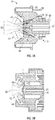
FIGS. 1A, 1B, and 1C are side views of representative examples of a spray gun having a coating cup affixed at the upper side of the spray gun, a representative example of the spray gun having a coating cup affixed at the lower side of the spray gun, and a representative example of a pressure fed version the spray gun, wherein the pressure is applied to the spray gun via a connection hose that leads, for example, to a pressure pot, a circulation system, or a pump. These figures also show a schematic presentation of a typical manual spray gun with spray gun body, air cap, fluid spray nozzle, fluid tip, air distribution channels, a paint cup, an and inlet air channel. -
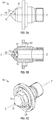
FIGS. 2A and 2B are representative cross-sectional views of the air cap and fluid spray nozzle assembly and one example of a fluid spray nozzle / air cap assembly in accordance with an embodiment that can be used having separate atomizing air distribution channels that provide atomizing airflow to the air cap openings and fan air distribution channel, providing fan airflow to air cap horn openings. -
FIGS. 3A-3B are representative cross-sectional views of the air cap and fluid spray nozzle assembly in a spraying configuration.FIG. 3B illustrates the embodiments ofFIGS. 2A-2B in operation and having a paint jet (i.e., a coating composition jet, atomizing airflow, and a fan airflow. -
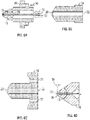
FIGS. 4A-4E illustrate representative examples of (A) a cross-sectional view of the air cap, (B) a frontal perspective view of the air cap, (C) a cross-sectional view of the air cap and fluid spray nozzle assembly, and examples of suitable configurations (D) and (E) of the air cap. One embodiment of an air cap with horns, fan air channel, and an atomizing air channel is shown. In a particular embodiment, an angle paint jet, i.e., coating composition jet/atomizing air flow of substantially 45 degrees is used. -
FIGS. 5A-5C illustrate representative examples of a side view, a cross-sectional view, and a perspective view of the of the fluid spray nozzle. A representative example of a substantially 45 degrees fluid spray nozzle having a fluid tip orifice and atomizing air bores is shown. -
FIGS. 6A-6D illustrate representative cross-sectional views of an example of the fluid spray nozzle in a non-spraying configuration and an example of a fluid spray nozzle having a tip rim. These figures also show one embodiment of a fluid spray nozzle having a needle and bores for the atomizing air. In a further embodiment, an angle paint jet/atomizing air flow of substantially 45 degrees is used. -
FIGS. 7A-7B show representative examples of schematic presentations of directions of the coating composition jet, atomization air flow, and fan air flow with (A) a cross-sectional view of the air cap and fluid spray nozzle assembly, (B) a detailed view of the orifice and air cap spray opening, and (C) a schematic representation of the rotational symmetry and the atomization air flow angle between the atomization air flow and the rotational axis Z-Z'. These figures also show a schematic presentation of a direction of the atomization air flow into the coating composition jet of substantially 45 degrees and of a direction of the atomization air flow into the coating composition jet of substantially 30 degrees. -
FIG. 8 illustrates a modified air cap with respect to the position and angle of the fan air outlets and the relationship between the air streams of the atomizing air and the fan air jets. - The features and advantages of the present invention will be more readily understood, by those of ordinary skill in the art, from reading the following detailed description. It is to be appreciated that certain features of the invention, which are, for clarity, described above and below in the context of separate embodiments, may also be provided in combination in a single embodiment. Conversely, various features of the invention that are, for brevity, described in the context of a single embodiment, may also be provided separately or in any sub-combination. In addition, references in the singular may also include the plural (for example, "a" and "an" may refer to one, or one or more) unless the context specifically states otherwise.
- Water-based coating compositions are coating compositions, wherein water is used as a solvent or thinner when preparing and/or applying the coating composition. Usually, aqueous coating compositions contain about 20% to 80% by weight of water, based on the total amount of the coating composition and optionally, up to about 15% by weight, preferably, below about 10% by weight of organic solvents, based on the total amount of the coating composition.
- The spray gun of the embodiment described herein or which can be suitable in the methods described herein is particularly suited as a manual (or hand-held) spray gun. A manual spray gun is a spray gun which is used manually by a human, i.e. a coating composition is manually sprayed with the spray gun by a human. A manual spray gun is not a spraying device used in or as a spraying robot or a spraying machine or robot or handled by a spraying machine or spraying robot. Manual spray guns are typically used for applying coating compositions in vehicle refinishing, particularly in vehicle repair coating in refinish body shops. However, the spray gun of the present invention can also be used in a spraying robot or a spraying machine or can be handled by a spraying robot or a spraying machine.
- Atomizing air (AA) is defined as the airflow or air volume that breaks the liquid paint jet, which will be used hereinafter synonymously with coating composition jet, coming from the fluid tip of the fluid spray nozzle, into small droplets. Fan air (FA) is defined as the airflow or air volume that pushes the atomized paint jet into a desired paint jet form, such as a spherical form, and preferably an elliptical cone.
- The spray gun in accordance with an embodiment and which can be used in the method of the embodiment is operable by using high air volume and high air pressure, measured at the air cap outlet.
- Air volumes of, for example, substantially 25 liters/minute (l/min) to 600 l/min, preferably substantially 100 l/min to 600 l/min, and more preferably substantially 200 l/min to 500 l/min, measured at the air cap outlet, can be used. Atomizing air volume and fan air volume can be separately in the range of substantially 25 l/min to 600 l/min, and preferably substantially 100 l/min to 500 l/min. A respective input air volume is selected accordingly.
- The atomizing air pressure can, for example, be in the range of substantially 0.5 bar to 5.0 bar, preferably substantially 1.0 bar to 5.0 bar, still more preferably substantially 2.0 to 4.0 bar, measured at the air cap outlet. The fan air pressure can be, for example, in the range of substantially 0.1 bar to 2.5 bar, preferably substantially 0.5 bar to 2.0 bar, and still more preferably substantially 1.0 bar to 2.0 bar, measured at the air cap outlet. Accordingly, an input air pressure of, for example, substantially 2.0 to 12.0 bar is needed. The respective input air pressure can be generates by a turbine compressor.
- The spray stream or coating composition jet is produced by using a gravity cup or pressurized carrier. Even if compressed air is preferably used and referred to herein throughout, other pressurized carriers, such as compressed gas other than air or a compressed gas mixture, can also be used.
- The spray gun and the method of the embodiments described herein has a fluid spray nozzle and an air cap which are both configured to direct an atomization air flow at an angle of substantially 10-75 degrees, preferably substantially 15-60 degrees, and more preferably substantially 30-45 degrees (relative to the coating composition jet) into the coating composition jet. Stated differently, the fluid spray nozzle and the air cap are both configured such that the angle formed by the central axis of the coating composition jet and the central axis of the atomization air flow is substantially 10-75 degrees, preferably substantially 15-60 degrees, and still more preferably substantially 30-45 degrees. The central axis of the coating composition jet is at a ninety degree angle relative to the fluid tip surface or laminar to the fluid tip opening.
- Accordingly, the fluid spray nozzle is configured such that it has the form of a substantially 10-75 degree, preferably substantially a 15-60 degree, and still more preferably substantially a 30-45 degree cone terminating to a substantially 10-75 degree, preferably substantially 15-60 degree, and still more preferably a substantially 30-45 degree angular fluid tip. Accordingly the air cap is formed with a central substantially 10-75 degree, preferably substantially 15-60 degree, and still more preferably substantially 30-45 degree angular air aperture (opening). The profile of the fluid spray nozzle is a substantially 10 -75 degree, preferably substantially 15-60 degree, and still more preferably 30-45 degree frustum, terminating at the substantially 10-75degree, preferably substantially 15-60 degree, and more preferably substantially 30-45 degree angular fluid tip, through which the coating composition is discharged (see
FIGS. 2 to 4 ). - The final atomized paint jet can be corrected to a very stable and very homogeneous spray cone by applying the correct fan air flow. During operation of the spray gun, 80 to 90% of the total atomization air volume is directed at an angle of 10-75 degrees, preferably 15-60 degrees, and more preferably 30-45 degrees (relative to the composition jet) into the coating composition jet. Accordingly, the fluid spray nozzle and the air cap can contain additional bores to direct the remaining part of the atomization air volume.
- Generally the fluid spray nozzle and the air cap of a spray gun form a unified system, i.e. a specific fluid spray nozzle requires a specific air cap configured to match; for example, the opening of the air cap has to be adjusted according to the diameter of the fluid tip of the nozzle.
- The fluid spray nozzle and the air cap of the spray gun, together with the air distribution channels, are configured to provide an atomizing air pressure to fan air pressure ratio (AA/FA ratio) of substantially 0.1 to 10, preferably substantially 8.0 to 1.5, and more preferably substantially 4.0 to 2.0. The AA/FA ratio can be, for example, 1.6 bar to 0.2 to 1.6 bar : 0.8 bar. The design of the fluid spray nozzle and the air cap can be configured in different ways in order to ensure the desired AA/FA ratio. The fluid spray nozzle and the air cap contain at least one air channel for the atomizing air and at least one air channel for the fan air. According to one embodiment, the diameter of the air channels can be selected such that the desired AA/FA ratio can be adjusted in the operation status of the spray gun. According to a further embodiment, means can be included for regulating the air flow volumes (and accordingly the air pressure) in the separate air channels at given air channel diameters. Air flow volumes can be regulated, for example, by air valves. Also, according to yet a further embodiment, both of the above measures, the air channel diameter and the regulation of the air flow volume by respective means, can be used. The selection of appropriate air channel diameters and air flow volume regulating means can be made by a person skilled in the art.
- In addition, the fluid spray nozzle or the air cap or both may contain bores to direct the atomization or the fan air flow. The number, diameter, and position of the respective bores may be selected by a person skilled in the art so as to achieve the desired air volume and air pressure.
- The manual spray gun in accordance with the present embodiment comprises the spray gun body, an air cap at the front of the spray gun body, and a fluid spray nozzle. The air cap is formed with horns in order to supply the fan air. The spray gun comprises at least two air distribution channels, one for the atomizing air and another for the fan air. According to one embodiment, the compressed air enters the spray gun body via an inlet air channel; e.g. a central inlet air channel. The inlet air channel is separated into the at least one atomizing air channel and at least one fan air channel.
- According to a further embodiment, the incoming compressed air may directly be divided at the air inlet into at least one atomization air stream and at least one fan air stream. The air distribution channels are configured accordingly. Preferably, the spray gun comprises a compressed air distribution system; i.e. it comprises at least one compressed air inlet channel and two separate air distribution channels - one for the atomization air and one for the fan air. The spray gun body preferably comprises means dividing the incoming air into a first air flow that provides atomizing air around the fluid spray nozzle and into a second air flow that provides the fan air to the horns of the air cap. One or more air channels for the atomizing and the fan air may be present.
- Separation and regulation of the compressed input air into atomizing air and fan air can be realized by means of air valves independently regulating the atomizing and fan air volume (and accordingly the air pressure).
- According to a further embodiment, the spray gun can additionally have pressure valves and digital read-out on the separate air channels, regulating separately the atomizing air flow and fan air flow to set the desired ratio AA/FA, measured at the air cap outlet. According to yet another embodiment, the spray gun may be coupled to a pressurized paint supply (coating composition) that can be a stand-alone pressure pot, a paint pump, a pressurized paint cup or gravity cup on the gun body. The pressure can be applied via a relief valve or by an auxiliary air supply connected to the spray gun air passages. An air pressure on the paint cup of, for example, substantially 0.1-6 bar or of substantially 0.1-1.5 bar may be required for the necessary paint flow, depending on the fluid tip diameter and angle in which the atomization air stream is directed into the paint jet. The fluid spray nozzle may have a fluid tip opening diameter of substantially 0.1 to 5 mm or substantially 0.7 to 2.5 mm.
- The spray gun body may have additional multiple parts and controls, as typically used in manual spray guns; for example, a flow regulator for regulating the flow of the coating composition, and other mechanisms necessary for proper operation of a manual spray gun known to those skilled in the art. Typically, multiple channels, connectors, connection paths, and mechanical controls can be assembled within the spray gun body.
- The previously described design of the fluid spray nozzle/air cap assembly, in combination with at least one atomizing air channel and the at least one fan air channel, permit adjustment of the desired AA/FA pressure ratio and direct the atomization air flow at the desired angle into the liquid coating composition jet.
- The embodiments described herein also relates to a fluid spray nozzle/air cap assembly, wherein A) the fluid spray nozzle and the air cap are configured to direct an atomization air flow at an angle of substantially 10 to 75 degrees, preferably substantially 15 to 60 degrees, and more preferably substantially 30 to 45 degrees, relative to the liquid coating composition jet, and B) the fluid spray nozzle and the air cap are configured to provide an atomizing air pressure to fan air pressure ratio of substantially 8.5 to 1, and preferably substantially 4 to 2
- The details, embodiments, and preferred embodiments of the fluid spray nozzle and the air cap of the fluid spray nozzle/air cap assembly are the same as described above for the fluid spray nozzle, the air cap, and the needle as part of the spray gun. The fluid spray nozzle/air cap assembly can be used in any type of spray gun, for example in a manual spray gun, and also in a spraying robot, a spraying machine, or any other spraying device.
- In an embodiment, a layer of a liquid coating composition is applied onto the substrate by the above described spray gun, with an atomizing air pressure to fan air pressure ratio of substantially 0.1 to 10, preferably substantially 8.0 to 1.5, and more preferably substantially 4.0 to 2.0.
- The spray gun and the fluid spray nozzle/air cap assembly for all liquid coating compositions and the method of use thereof can preferably be used in vehicle repair coating, but is also applicable to vehicle production line painting as well as coating large vehicles and transportation vehicles such as busses and railroad cars. While the substrates to be coated are preferably vehicle bodies and vehicle body parts, the spray gun described herein may be used for applying liquid coating compositions onto other substrates in other fields of application; e.g. onto wood, plastic, leather, paper, and other metal substrates as well as onto woven and non-woven fabrics.
- Typical water-based coating compositions comprise binders, optionally cross-linkers, and a liquid carrier. The liquid carrier is water and may comprise in addition one or more organic solvents. Binders are, for example, compounds with functional groups with active hydrogen. These compounds can be oligomeric or polymeric binders. In order to ensure sufficient water dilutability of the binders, they are modified to render them hydrophilic, e.g., they can be anionically modified by incorporation of acid groups. The water-based coating compositions may contain cross-linkers, for example, polyisocyanates with free isocyanate groups. Examples of polyisocyanates are any number of organic di- or higher functional isocyanates with aliphatically, cycloaliphatically, araliphatically and/or aromatically bound free isocyanate groups. The polyisocyanate cross-linkers are those commonly used and commercially available in the paint industry and are described in detail in the literature.
- The water-based coating compositions may contain pigments, solid pigments as well as effect pigments, fillers, and/or usual coating additives. Examples of usual coating additives are light stabilizers, for example, based on benztriazoles and HALS (hindered amine light stabilizer) compounds, flow control agents based on (meth)acrylic homopolymers or silicon oils, rheology-influencing agents, such as, highly disperse silicic acid or polymeric urea compounds, thickeners, such as, cross-linked polycarboxylic acid or polyurethanes, antifoaming agents, and wetting agents.
- The water-based coating compositions to be applied with the spray gun and the fluid spray nozzle/air cap assembly be any kind of paints such as waterborne clear coats, water-borne top coats, water-borne base coats, and water-borne primers.
- The water-based coating composition may be applied onto a pre-coated substrate. Suitable substrates are metal and plastics substrates, in particular, the substrates known in the automotive industry, such as for example iron, zinc, aluminium, magnesium, stainless steel or the alloys thereof, together with polyurethanes, polycarbonates or polyolefines. In the case of a multilayer coating with a water-based base coat composition and water-based clear coat composition, the clear coat layer may be applied onto the base coat layer either after drying or curing or wet-on-wet, optionally after briefly flashing off. They water-based coating compositions may comprise a one-component or two-component coating . After the layer of the water-based coating composition has been applied, it may initially be flashed off to remove water and optionally present organic solvent. Curing may then proceed at ambient temperature or thermal curing may proceed at temperatures of, for example, substantially 40 to 140°C, and preferably at substantially 40 to 60°C.
- In accordance with an embodiment, the spray gun comprises a
spray gun body 12, (e.g.FIGS. 1A, 1B, and 1C ), a fluid spray nozzle/air cap assembly comprising anair cap assembly 14, afluid spray nozzle 18 having afluid tip orifice 20, at least one atomization air distribution channel 30 (e.g.FIG. 3A ) for distributing an atomizingair 60, and at least one fanair distribution channel 26 for distributingfan air 58. The fluid spray nozzle andair cap assembly 14 are configured to direct atomizingair 60 to form anatomization air flow 24 evenly in a rotational symmetry around a rotational axis Z-Z' of the fluid spray nozzle and all around thefluid tip orifice 20 at an atomization air flow angle 84 (e.g.FIG. 4C ) in a range of from substantially 10 to 75 degrees, relative to the rotational axis Z-Z. Thisatomization air flow 24 and the fan air are provided at an atomization air pressure to fan air pressure ratio of substantially 0.1 to 10. - The atomizing air pressure and air volume stream, as well as the fan air pressure and air volume stream, can be regulated by the nozzle and air cap design. The atomizing air pressure and the fan air pressure can be regulated by configuring relative sizes of the atomization
air distribution channel 30 and the fan air distribution channel 26 (e.g.,FIG. 2A ), using one or more regulators to regulate air supplied to the atomizationair distribution channel 30 and the fanair distribution channel 26, providing separate pressurized air of the desired air pressures to the atomizationair distribution channel 30, the fanair distribution channel 26, or a combination thereof._ The spray gun can be configured to provide from substantially 0.1 to 600 liter/min, and preferably from 0.1 to 500 liter/min air volume stream to the air cap opening 66 (e.g.FIGS. 2A and4A ) and in a range of from substantially 0 to 500 liter/min air volume stream up to the fan air outlets 80 (e.g.FIGS. 3A and 3B ,. The diameter of theair cap opening 66 and the diameter of the air capfan air outlets 80 can be sized to regulate the ratio of the atomizing air pressure and the fan air pressure in with a desired air volume to assure a desired spray pattern. - Referring again to
FIGS. 1A, 1B, and 1C the spray gun can further comprise one or moreair distribution channels paint cup 42, andinlet air channel 44. Thepaint cup 42 can The fluid spray nozzle and the air cap can be assembled to form the fluid spray nozzle and air cap assembly via conventional mechanisms, such as matching screw tracks, clippers, or other mechanisms to assemble the parts. The fluid spray nozzle may comprise aspray needle 22 that slides along the rotational axis Z-Z' of the fluid spray nozzle in the directions shown by thearrow 32 between a closed position and an open position to close or open thefluid tip orifice 20 inside the fluid spray nozzle (FIGS. 2A ,3 , and6 ), respectively. By controlling the position of the spray needle between the closed and the open positions, the amount of coating spraying through the fluid tip orifice can also be controlled. Once properly assembled, the fluid spray nozzle's fluid tip orifice can be positioned flush with the aircap spray opening 66. Theexternal plane 68 of the aircap spray opening 66 and the outmost tip plane of thefluid tip orifice 34 are projected planes perpendicular to the rotational axis Z-Z'. The outmost tip plane of thefluid tip orifice 34 can be protruding or recessed relative to theexternal plane 68 of the aircap spray opening 66 in a range of from substantially 0 to 2 mm in one example, substantially 0 to 1 mm in another example, and substantially 0 to 0.5 mm in yet another example. Representative examples of cross-sectional views of the fluid spray nozzle and air cap assemblies in spray operation configurations are shown inFIG. 3A and 3B . - The air cap opening inner-
surface 62 is a surface inside the air cap towards the fluid spray nozzle immediately around theair cap opening 66 and can be the entire (FIGS. 2A ,3A , and4A-4D ) or a portion (FIGS. 2B ,3B , and4E ) of the surface inside the air cap. - The atomization air flow is directed through an atomizing air passage 83 a space formed by the air cap opening inner-
surface 62 of the air cap (FIGS. 4A - 4E ) and theexternal nozzle surface 72 of the fluid spray nozzle (FIGS. 5A-5C ) at the fluid tip orifice end of the fluid spray nozzle in a properly assembled fluid spray nozzle and air cap assembly. The air cap opening inner-surface 62 can be configured to have an air cap opening inner-surface angle 84 in a range of from substantially 10 to 75 degrees relative to the rotational axis Z-Z'. The air cap opening inner-surface angle 84 can be measured between an air cap opening inner-surface extension C-C' and the rotational axis Z-Z' on a perspective cross-sectional plane of the air cap intersecting the rotational axis Z-Z' and parallel to the rotational axis Z-Z' (FIGS. 4A and4E ). Theexternal nozzle surface 72 is configured to have an external nozzle surface angle 74 (e.g.FIG. 5A ) in a range of from substantially 10 to 75 degrees, relative to the rotational axis Z-Z'. The external nozzle surface angle 74 (FIGS. 5A ) can be measured between an external nozzle surface extension N-N' and the rotational axis Z-Z' on a perspective cross-section plane of the fluid spray nozzle intersecting the rotational axis Z-Z' and parallel to the rotational axis Z-Z'. The air cap opening inner-surface angle 84 and externalnozzle surface angle 74 can be substantially the same, meaning that the difference in the air cap opening inner-surface angle 84 and the externalnozzle surface angle 74 is less than 66 degrees. This provides protection when an inner-surface angle having a different external nozzle surface angle, within the ranges mentioned, is used; e.g.surface angle 84 is seventy-five degrees andangle 74 is ten degrees; i.e. the difference is at its maximum of sixty-five degrees which is lower than sixty-six degrees. The difference in the air cap opening inner-surface angle 84 and externalnozzle surface angle 74 can be in a range of from substantially 0 to 65 degrees in one example, substantially 0 to 15 degrees in another example, substantially 0 to 10 degrees in yet another example, substantially 0 to 5 degrees in yet another example, and substantially 0 to 2 degrees in a further example. - The
fluid spray nozzle 18 can have a total external nozzle surface angle 76 (e.g.FIG. 5B ) that is an angle defined by the external nozzle surface 72 (FIG. 5C ). Theexternal nozzle surface 72 can be configured to be cone shaped. The fluid spray nozzle can further configured to have an inner-nozzle surface having an inner-nozzle surface angle 76 measured from the inner-nozzle surface relative to the rotational axis Z-Z'. A total inner-nozzle surface angle 78 (FIG. 5B ) is an angle defined by the inner-nozzle surface. Thefluid spray nozzle 18 can comprise one or more atomization air distribution channels 30 (e.g.,FIG. 3A ). - The
air cap 14 can further comprise two or more fan air horns 28 (e.g.,FIGS. 4A-4B ), each comprising one or morefan air outlets 80. When in operation and supplied with thefan air 58 through the fanair distribution channel 26, the fan air outlets can be configured to deliverfan air jets 52 at a fanair jet angle 54 in a range of from 15 to 89 degrees relative to the rotational axis Z-Z' (e.g.,FIG. 7A ). The air cap can further comprise one or more supporting air channels 82 (e.g.,FIG. 3 ). The fan air jets are used for shaping fan pattern of thecoating composition jet 14. A fraction of the atomizingair 60 can be configured to jet through the supportingair channels 82 to form supportingair jets 46. The supporting air jets can be a fraction of the atomizing air, such as in a range of from substantially 0.01% to 99% in one example, substantially 0.01% to 50% in another example, substantially 0.01% to 20% in another example, and substantially 0.01% to 10% in yet another example, and 0.01% to 5% in yet another example, the percentage based on the air volumes of the supporting air jet and the atomizing air. The supporting air jets can help to keep the air cap clean and also provide air jets for shaping the fan shape of thecoating composition jet 50. - The fluid spray nozzle and air cap assembly is free from any structure disrupting or changing the
atomization air flow 24 at the atomization air flow angle 84 (e.g.,FIGS. 4A to 4C ) around thefluid tip orifice 20 and the air cap spray opening 66 (e.g.,FIGS. 2A and 2B ). The fluid spray nozzle and air cap assembly is configured to direct theatomization air flow 24 at the atomizationair flow angle 84. The fluid tip orifice can be configured to be at the immediate cone tip end of the fluid spray nozzle defined by a cone shapedexternal nozzle surface 72 with the outmost plane of thefluid tip orifice 34 intersecting directly with theexternal nozzle surface 72. The air cap opening inner-surface 62 can directly intersect theexternal plane 68 of the aircap spray opening 66. The fluid tip orifice can be configured to be at the immediate cone tip end of the fluid spray nozzle defined by a cone shaped external nozzle surface 72 (FIG. 5A ) with the outmost tip plane of thefluid tip orifice 34 intersecting directly with theexternal nozzle surface 72, and the air cap opening inner-surface 62 is directly intersects theexternal plane 68 of the aircap spray opening 66. -
FIG. 6 shows representative examples of details of the spray gun with the needle at a closed position within the fluid spray nozzle (FIGS. 6A-6C ). At the closed position, thecoating 86 can be supplied to the fluid spray nozzle. However, no coating is sprayed out of the fluid tip orifice. The atomizingair 60 can be supplied independent from thecoating 86. The fluid spray nozzle can have a tip rim 36 (FIG. 6D ). The tip rim can have atip rim height 56, the distance between the outmost plane of thefluid tip orifice 34 and the intersection point with theexternal nozzle surface 72 is in a range of from substantially 0 to 1.0 mm in one example, substantially 0 to 0.8 mm in another example, substantially 0 to 0.6 mm in yet another example, substantially 0 to 0.4 mm in yet another example, substantially 0 to 0.2 mm in yet another example, and substantially 0 to 0.1 mm in a further example. - The air cap can have an air cap rim 70 immediately around the air cap opening 66 (
FIGS. 4D-4E ) with an aircap rim height 64 measured from theexternal plane 68 of the aircap spray opening 66 to the air capexternal surface 16. The aircap rim height 64 may be in a range of from substantially 0 to 1.0 mm in one example, substantially 0 to 0.8 mm in another example, substantially 0 to 0.4 mm in yet another example, substantially 0 to 0.2 mm in yet another example, and substantially 0 to 0.1 mm in a further example. -
Figure 7 shows schematic presentations of the spray gun in a spraying configuration with the spray needle in an open position allowing thecoating 86 to spray out of thefluid tip orifice 20 along the direction of the rotational axis Z-Z'. The atomizingair 60 is supplied through the atomizationair distribution channels 30 forming theatomization air flow 24 flowing through the atomizingair passage 83 and jetting out of the aircap spray opening 66 at the atomizationair flow angle 84. The liquid coating composition jet is further atomized by theatomization air flow 24 after exiting thefluid tip orifice 20. Thefan air 58 is supplied through the fanair distribution channels 26 and jets out of thefan air outlets 80 forming thefan air jets 52 at the fanair jet angle 54 relative to the rotational axis Z-Z'. The supportingair jets 46 can be jetted out of the supportingair channels 82 at a supportingair jet angle 48 relative to the rotational axis Z-Z'. The supportingair jet angle 48 can be in a range of from 10 to 75 degree. The supportingatomization air jets 82 can give additional atomization and can prevent the atomized coating returning back to the air cap surface. Theatomization air flow 24 can form a continuous cone shaped air flow around thefluid tip orifice 20 through the atomizing air passage 82 (FIG. 7B ). The atomizingair flow 24 can impact the liquidcoating composition jet 50 causing the coating to atomize into small droplets. - The atomization
air flow angle 84 can be measured between the projectedatomization air flow 24 and the rotational axis Z-Z' of the fluid spray nozzle on aperspective cross-section plane 88 intersecting the rotational axis Z-Z' and parallel to the rotational axis Z-Z' (FIG. 7C ). The atomizationair flow angle 84 can be in a range of from substantially 10 to 75 degrees in one example, substantially 10 to 20 degree in another example, substantially 20-30 degree in yet another example, substantially 30 to 40 degree in yet another example, substantially 40 to 50 degree in yet another example, substantially 50 to 60 in yet another example, and substantially 60 to 75 degree in a further example. In a further example, the air cap and spray fluid nozzle assembly can have an external nozzle surface angles 74 at about 60 degrees. In an even further example, the air cap and spray fluid nozzle assembly can have an externalnozzle surface angle 74 of about 45 degrees. In yet a further example, the air cap and spray fluid nozzle assembly can have an externalnozzle surface angle 74 of about 30 degrees. - The substrate can be coated with coating layers sprayed using the same or different spray guns. The substrate can be spray coated in horizontal or vertical positions. The spray gun of can be used to produce any coating layers on a substrate, such as a primer coating layer, a basecoat coating layer, a topcoat coating layer, a clearcoat coating layer, or a combination thereof. The spray gun can also be used to produce one or more additional coating layers on a substrate already coated with one or more coating layers. In one example, an article can be coated with one or more basecoat layers with any conventional spray gun and subsequently coated with one or more clearcoat coating layers with the spray gun in accordance with the embodiments descried herein. In another example, an article can be coated with one or more basecoat coating layers and one or more clearcoat coating layers with the spray gun in accordance with the embodiments described herein.
- Coating compositions suitable for using the spray gun in accordance with the embodiments described herein can be any coating compositions that are suitable for spraying with a spray gun. The coating composition can be a solvent borne coating composition that comprises from substantially 10% to 90% of one or more organic solvents, or a waterborne coating composition that comprises from substantially 20% to 80% of water based on the total weight of the coating composition.
- The coating composition can be a "two-pack coating composition", also known as a 2K coating composition, with two components of the coating composition stored in separate containers and sealed to increase the shelf life of the components of the coating composition during storage. The coating composition can be a "one-pack coating composition", also known as a IK coating composition, such as a radiation curable coating composition or a coating composition contains cross linkable components and blocked crosslinking components such as blocked isocyanates that can be deblocked under certain deblocking conditions.
- The coating composition can be a mono-cure or a dual cure coating composition. A mono-cure coating composition can be cured by one curing mechanism. In one example, a mono-cure coating composition can contain one or more components having acrylic double bonds that can be cured by UV radiation in which the double bonds of the acrylic groups undergo polymerization to form a crosslinked network. In another example, a mono-cure coating composition can be cured by chemical crosslink and contain crosslinking groups and cross linkable groups that can react to form a crosslinked network. A dual-cure coating composition is a coating composition that can be cured by two curing mechanisms, such as UV radiation and chemical crosslink
- In accordance with a further embodiment, reference is made to
FIG. 8 which illustrates a modifiedair cap 14; specifically, with respect to the position and angle of thefan air outlets 80 and the relationship between the air streams of the atomizingair 24 and thefan air jets 52. As will be demonstrated, this device provides an AA/FA pressure ratio in a range of from substantially 8.0 to 1.5 accompanied by significant improvement in Transfer Efficiency. - As used hereinbelow, the fan air jet intersecting distance d2 represents the shortest distance between the fan air jet intersecting point (FP) and the
external plane 68 of the air cap spray opening. The atomizing air intersecting distance d1 is the shortest distance between the atomizing air intersecting point (AP) and theexternal plane 68 of the aircap spray opening 66. The fan air jet intersecting point (FP) represents the intersection of rotational axis Z-Z' of thefan air jets 52. FP can be determined by the either changing the angle 54 (Alpha 2) or by changing the height of the FA borings 24 or a combination of both. The fan air jet intersecting point (FP) can be determined by extending the rotational axis Y-Y' of thefan air outlet 80 until it intersects with rotational axis Z-Z'. FP can be determined by the either changing the angle 54 (Alpha 2) or by changing the height of the FA borings 8 or a combination of both. - In the current embodiment, the fan air jet intersecting distance d2 is greater that the atomizing air intersecting distance d1. The ratio d2/d1 can be in the range of from 1.1 to 100 in one example, 1.1 to 50 in another example, 1.1 to 20 in yet another example, and 1.1 to 10 in another example. In a further example, d1 = 2mm and d2 is in a range of from 6mm to 16 mm. In a further example, d1 = 4mm and d2 is in a range of from 6 to 16 mm.
- The atomizing air intersecting point (AP) is the intersection of rotational axis Z-Z' and the stream of atomizing
air 24 and can be determined by extending the air cap opening inner-surface extension C-C' until it intersects with rotational axis Z-Z'. A previously described, theatomization airflow angle 84 is also defined asangle Alpha 1 in a range of from 10 to 75 degrees relative to the rotational axis Z-Z'. The air cap openinginner surface 62 can be configured to have an air cap opening inner surface angle in a range of from 10 to 75 degrees relative to the rotational axis Z-Z'. - As previously described, the fan air outlets can be configured to deliver
fan air jets 52 at a fanair jet angle 54, also defined asAlpha 2 in a range of from substantially 15 to 89 degrees relative to the rotational axis Z-Z'. Thus,Alpha 2 can range from 15-89 degrees in one example. 20 to 75 degrees in another example, 20 to 50 degrees in yet another example, and 20 to 40 degrees in yet a further example. It should be noted that the ranges ofAlpha 1 andAlpha 2 should be such that the fan air jet intersecting distance d2 is greater than the atomizing air intersecting distance d1. For example, whenAlpha 1 is configured to be in a low range,Alpha 2 must be configured such that d2 is greater than d1. - The embodiments described herein offer the benefits of improved atomization and coating transfer efficiency. It is possible to spray with conventional atomizing air settings of 1-5 bar at the air cap with a transfer efficiency between 65-92% while still assuring good atomization and fine liquid paint droplets. The conical angular atomization pushes most of the liquid coating into the center of the spray brush. The horn air can be applied at different heights and at different volumes into the atomized liquid coating enabling the formation of a nice 200-320 mm spray pattern width.
- While at least one exemplary embodiment has been presented in the foregoing detailed description, it should be appreciated that a vast number of variations exist. It should also be appreciated that the exemplary embodiment or exemplary embodiments are only examples, and are not intended to limit the scope, applicability, or configuration of the present disclosure in any way. Rather, the foregoing detailed description will provide those skilled in the art with a convenient road map for implementing an exemplary embodiment, it being understood that various changes may be made in the function and arrangement of elements described in an exemplary embodiment without departing from the scope of the present disclosure as set forth in the appended claims and their legal equivalents.
Claims (15)
- A spray gun comprising:a spray gun body (12);an air cap (14);a fluid spray nozzle (18) having a fluid tip (20);at least one air distribution channel (30) for atomizing air (60); andat least one air distribution channel (26) for fan air (58),wherein the fluid spray nozzle (18) and the air cap (14) are configured to direct an atomization air flow (24) in a rotational symmetry around a rotational axis (Z-Z') of the fluid spray nozzle and around the fluid tip (20) at an angle of 10 to 75 degrees relative to the liquid coating composition jet, into the pre-atomized coating composition jet (50), andwherein the fluid spray nozzle (18) and the air cap (14) are configured to direct an atomization air pressure to fan air pressure ratio of 8.0 to 1.5 by selecting appropriate air distribution channel diameters and/or by including appropriate means for regulating the air flow volumes in the separate air distribution channels at given air distribution channel diameters.
- The spray gun of claim 1, wherein fluid spray nozzle (18) and the air cap (14) are configured to direct an atomization air flow (24) at an angle of 15 to 60 degrees, preferably 30 to 45 degrees, relative to the coating composition jet, into the coating composition jet.
- The spray gun of claim 1, wherein the fluid spray nozzle (18) and the air cap (14) are configured to provide an atomizing air pressure to fan air pressure ratio of 4.0 to 2.0.
- The spray gun of claim 3, wherein the air cap (14) contains horns (28) for the fan air (58).
- The spray gun of claim 4, wherein the air cap (14) and the fluid spray nozzle (18) contain additional bores to direct the atomizing air flow (24).
- The spray gun of claim 1 further comprising means for regulating the atomizing and fan air volume.
- The spray gun of claim 1, wherein the spray gun is a manual spray gun.
- A fluid spray nozzle/air cap assembly, comprising:a fluid spray nozzle (18) having a fluid tip (20); andan air cap (14), the a fluid spray nozzle (18) and the air cap (14) configured to direct an atomization air flow (24) in a rotational symmetry around a rotational axis (Z-Z') of the fluid spray nozzle and around the fluid tip (20) at an angle of 15 to 60 degrees, preferably at an angle of 30 to 45 degrees, relative to the liquid coating composition jet, into the liquid coating composition jet, and wherein the fluid spray nozzle (18) and the air cap (14) are configured to provide an atomizing air pressure to fan air pressure ratio of 2.0 to 1.5 by selecting appropriate air distribution channel diameters and/or by including appropriate means for regulating the air flow volumes in the separate air distribution channels at given air distribution channel diameters.
- A method for applying a layer of a liquid coating composition onto a substrate with a spray gun, the method comprising;
providing a spray gun comprising a spray gun body (12), an air cap (14), a fluid spray nozzle (18) having a fluid tip (20), at least one air distribution channel (30) for atomizing air (60), and at least one air distribution channel (26) for fan air (58), comprising:directing an atomization air flow (24) in a rotational symmetry around a rotational axis (Z-Z') of the fluid spray nozzle and around the fluid tip (20) at an angle of 15 to 60 degrees, relative to the liquid coating composition jet, into the liquid coating composition jet (50);providing an atomizing air pressure to fan air pressure ratio of 8 to 1.5; andapplying at least one layer of the liquid coating composition onto the substrate. - The method of claim 9, wherein the liquid coating composition is applied with an atomizing air pressure to fan air pressure ratio of 2.0 to 1.5.
- The method of claim 9, wherein the liquid coating composition is applied with an atomizing air pressure of 0.5 to 5.0 bar, and preferably 1.0 to 5.0 bar, measured at the air cap outlet, or wherein the liquid coating composition is applied with a fan air pressure of 0.10 to 2.5 bar, and preferably 0.5 to 2.0 bar, measured at the air cap outlet.
- The method of claim 9, wherein the liquid coating composition is applied with a fan air pressure of 0.5 to 2.0 bar, measured at the air cap outlet, and an atomizing air pressure of 2.0 to 4.0 bar, measured at the air cap outlet.
- The method of claim 9, wherein the liquid coating composition is applied with a fan air pressure of 2.0 to 4.0 bar, measured at the air cap outlet and an atomizing air pressure of 1.0 to 2.0 bar, measured at the air cap outlet.
- The method of claim 9 wherein the spray gun is handled manually, by a spraying machine.
- The spray gun of claim 1, wherein a ratio d2/d1 is in the range of from 1.1 to 100, wherein a fan jet intersecting distance d2 represents the shortest distance between a fan air jet intersecting point (FP) and an external plane of an air cap spray opening, an atomizing air intersecting distance d1 is the shortest distance between the atomizing air intersecting point (AP) and the external plane of the air cap spray opening; wherein FP represents the intersection of rotational Z-Z' and FP can be determined by extending a rotational axis Y-Y' of a fan air outlet until it intersects with rotational axis Z-Z'.
Applications Claiming Priority (1)
| Application Number | Priority Date | Filing Date | Title |
|---|---|---|---|
| PCT/US2015/019024 WO2016140682A1 (en) | 2015-03-05 | 2015-03-05 | Spray gun with high transfer efficiency and method for use thereof |
Publications (2)
| Publication Number | Publication Date |
|---|---|
| EP3265237A1 EP3265237A1 (en) | 2018-01-10 |
| EP3265237B1 true EP3265237B1 (en) | 2020-11-04 |
Family
ID=52686519
Family Applications (1)
| Application Number | Title | Priority Date | Filing Date |
|---|---|---|---|
| EP15710692.3A Active EP3265237B1 (en) | 2015-03-05 | 2015-03-05 | Spray gun with high transfer efficiency and method for use thereof |
Country Status (5)
| Country | Link |
|---|---|
| US (1) | US20180050354A1 (en) |
| EP (1) | EP3265237B1 (en) |
| JP (1) | JP6602882B2 (en) |
| CN (1) | CN107427852A (en) |
| WO (1) | WO2016140682A1 (en) |
Families Citing this family (13)
| Publication number | Priority date | Publication date | Assignee | Title |
|---|---|---|---|---|
| CN115814972A (en) * | 2017-09-30 | 2023-03-21 | 宁波市威优特电器有限公司 | Spray gun atomization regulation control device |
| WO2019109042A1 (en) * | 2017-11-30 | 2019-06-06 | KOERNER, Michael R. | Systems for applying coating compositions utilizing a high transfer efficiency applicator and corresponding methods |
| WO2021207425A1 (en) | 2020-04-07 | 2021-10-14 | Yoanna Gouchtchina | Dermal spray apparatus and method |
| CN111905941B (en) * | 2020-08-07 | 2021-06-04 | 东华大学 | A kind of control method of fan-shaped spray flow field |
| EP4213998B1 (en) * | 2020-09-16 | 2026-01-28 | Graco Minnesota Inc. | Fan air lever for a spray gun |
| CN112742619B (en) * | 2020-12-24 | 2024-05-28 | 中国船舶重工集团长江科技有限公司 | Atomized air cap |
| CN113468686B (en) * | 2021-06-28 | 2023-09-29 | 成都飞机工业(集团)有限责任公司 | Reservation method for assembly gap between woven air inlet channel and peripheral part |
| WO2023046257A1 (en) * | 2021-09-21 | 2023-03-30 | Polyplan-GmbH Polyurethan-Maschinen | Method for discharging a liquid using a nozzle device |
| US12376665B2 (en) | 2021-10-14 | 2025-08-05 | Kozhya LLC Sp. z o.o. | Dermal spray apparatus with disposable cartrdige and method |
| USD1033635S1 (en) | 2022-05-09 | 2024-07-02 | Quantum Skin SP Z O.O | Dermal spray nozzle |
| USD1038383S1 (en) | 2022-05-09 | 2024-08-06 | Kozhya LLC Sp. z o.o. | Dermal spray apparatus |
| USD1046122S1 (en) | 2022-05-09 | 2024-10-08 | Quantum Skin Limited Liability Company | Dermal spray cartridge |
| USD1035867S1 (en) | 2022-05-09 | 2024-07-16 | Kozhya LLC Sp. z o.o. | Dermal spray apparatus |
Citations (1)
| Publication number | Priority date | Publication date | Assignee | Title |
|---|---|---|---|---|
| EP0364311A1 (en) * | 1988-09-13 | 1990-04-18 | Sames S.A. | Pneumatic spraying device for liquids having a flat spraying nozzle |
Family Cites Families (13)
| Publication number | Priority date | Publication date | Assignee | Title |
|---|---|---|---|---|
| US1689848A (en) * | 1924-06-23 | 1928-10-30 | Peerless Pneumatic Systems Inc | Spray gun |
| GB508719A (en) * | 1937-01-25 | 1939-07-05 | Albert Krautzberger | Improvements in apparatus for spraying paint and other substances |
| US5344078A (en) * | 1993-04-22 | 1994-09-06 | Ransburg Corporation | Nozzle assembly for HVLP spray gun |
| US5409162A (en) * | 1993-08-09 | 1995-04-25 | Sickles; James E. | Induction spray charging apparatus |
| JP2002219403A (en) * | 2001-01-29 | 2002-08-06 | Sekisui House Ltd | Spatter pattern adjustment method |
| US7032839B2 (en) * | 2003-12-30 | 2006-04-25 | 3M Innovative Properties Company | Liquid spray gun with manually separable portions |
| US8113445B2 (en) * | 2008-03-11 | 2012-02-14 | Illinois Tool Works Inc. | Spray gun having air cap with unique spray shaping features |
| DE202010007355U1 (en) * | 2010-05-28 | 2011-10-20 | Sata Gmbh & Co. Kg | Nozzle head for a spraying device |
| US9302281B2 (en) * | 2011-01-24 | 2016-04-05 | Carlisle Fluid Technologies, Inc. | High swirl air cap |
| US8820663B2 (en) * | 2011-08-03 | 2014-09-02 | Spraying Systems Co. | Pressurized air assisted spray nozzle assembly |
| US8524312B2 (en) * | 2011-11-16 | 2013-09-03 | Csl Silicones Inc. | Applicator for spraying elastomeric materials |
| EP2931787A2 (en) | 2012-12-17 | 2015-10-21 | Solvay Specialty Polymers USA, LLC. | Polyaryl ether polymers end-capped with phenolic amino acids |
| JP2016524532A (en) * | 2013-06-07 | 2016-08-18 | コーティングス フォーリン アイピー カンパニー, エルエルシーCoatings Foreign IP Co., LLC | Spray gun and spraying method |
-
2015
- 2015-03-05 EP EP15710692.3A patent/EP3265237B1/en active Active
- 2015-03-05 CN CN201580078641.1A patent/CN107427852A/en active Pending
- 2015-03-05 US US15/555,870 patent/US20180050354A1/en not_active Abandoned
- 2015-03-05 JP JP2017546777A patent/JP6602882B2/en active Active
- 2015-03-05 WO PCT/US2015/019024 patent/WO2016140682A1/en not_active Ceased
Patent Citations (1)
| Publication number | Priority date | Publication date | Assignee | Title |
|---|---|---|---|---|
| EP0364311A1 (en) * | 1988-09-13 | 1990-04-18 | Sames S.A. | Pneumatic spraying device for liquids having a flat spraying nozzle |
Also Published As
| Publication number | Publication date |
|---|---|
| EP3265237A1 (en) | 2018-01-10 |
| CN107427852A (en) | 2017-12-01 |
| US20180050354A1 (en) | 2018-02-22 |
| WO2016140682A1 (en) | 2016-09-09 |
| JP2018508353A (en) | 2018-03-29 |
| JP6602882B2 (en) | 2019-11-06 |
Similar Documents
| Publication | Publication Date | Title |
|---|---|---|
| EP3265238B1 (en) | Spray gun with a hollow needle to assure gravity feed and method for use thereof | |
| US20180050354A1 (en) | Spray gun with high transfer efficiency and method for use thereof | |
| US20200171519A1 (en) | Spray gun and spray method | |
| US10821454B2 (en) | Spray gun with a hollow needle and single stage or two stage nozzle and method for use thereof | |
| US9233484B2 (en) | Spray device and use thereof | |
| CA2760093A1 (en) | System and method for delivering fluid through horns of an air cap for applying multiple component material | |
| KR102646878B1 (en) | Spraying nozzle with pre-atomization narrowing, and spraying head and spraying device comprising such a nozzle | |
| CN101909764A (en) | Method of siphoning a catalyst into an atomized coating composition | |
| JP2009273976A (en) | Spray gun for coating of inner surface | |
| CN102239010B (en) | The method used to form the coating | |
| CN102202799A (en) | Device for introducing catalyst into atomized coating composition | |
| CN102458671A (en) | Spraying method and use thereof | |
| US20120282413A1 (en) | Method for spraying multiple components | |
| EP2373429B1 (en) | Method for controlling the viscosity of a sprayable mixture | |
| WO2010075489A2 (en) | Method for producing sprayable lacquer | |
| EP2445649A1 (en) | Spray device for catalyst atomization | |
| US6733842B1 (en) | Process for the high-speed rotary application of liquid coating agents | |
| US20110274931A1 (en) | Method for controlling the viscosity of a sprayable mixture | |
| JP2004255224A (en) | Atomizing spray gun | |
| ITTO950265U1 (en) | AUTOMATIC GUN FOR FINISHING LEATHER BY PAINTING, RESIN OR SIMILAR |
Legal Events
| Date | Code | Title | Description |
|---|---|---|---|
| STAA | Information on the status of an ep patent application or granted ep patent |
Free format text: STATUS: THE INTERNATIONAL PUBLICATION HAS BEEN MADE |
|
| PUAI | Public reference made under article 153(3) epc to a published international application that has entered the european phase |
Free format text: ORIGINAL CODE: 0009012 |
|
| STAA | Information on the status of an ep patent application or granted ep patent |
Free format text: STATUS: REQUEST FOR EXAMINATION WAS MADE |
|
| 17P | Request for examination filed |
Effective date: 20161220 |
|
| AK | Designated contracting states |
Kind code of ref document: A1 Designated state(s): AL AT BE BG CH CY CZ DE DK EE ES FI FR GB GR HR HU IE IS IT LI LT LU LV MC MK MT NL NO PL PT RO RS SE SI SK SM TR |
|
| AX | Request for extension of the european patent |
Extension state: BA ME |
|
| RIN1 | Information on inventor provided before grant (corrected) |
Inventor name: DELSARD, BERT |
|
| DAV | Request for validation of the european patent (deleted) | ||
| DAX | Request for extension of the european patent (deleted) | ||
| STAA | Information on the status of an ep patent application or granted ep patent |
Free format text: STATUS: EXAMINATION IS IN PROGRESS |
|
| 17Q | First examination report despatched |
Effective date: 20190329 |
|
| GRAP | Despatch of communication of intention to grant a patent |
Free format text: ORIGINAL CODE: EPIDOSNIGR1 |
|
| STAA | Information on the status of an ep patent application or granted ep patent |
Free format text: STATUS: GRANT OF PATENT IS INTENDED |
|
| INTG | Intention to grant announced |
Effective date: 20200602 |
|
| GRAS | Grant fee paid |
Free format text: ORIGINAL CODE: EPIDOSNIGR3 |
|
| GRAA | (expected) grant |
Free format text: ORIGINAL CODE: 0009210 |
|
| STAA | Information on the status of an ep patent application or granted ep patent |
Free format text: STATUS: THE PATENT HAS BEEN GRANTED |
|
| AK | Designated contracting states |
Kind code of ref document: B1 Designated state(s): AL AT BE BG CH CY CZ DE DK EE ES FI FR GB GR HR HU IE IS IT LI LT LU LV MC MK MT NL NO PL PT RO RS SE SI SK SM TR |
|
| REG | Reference to a national code |
Ref country code: GB Ref legal event code: FG4D |
|
| REG | Reference to a national code |
Ref country code: CH Ref legal event code: EP |
|
| REG | Reference to a national code |
Ref country code: AT Ref legal event code: REF Ref document number: 1330112 Country of ref document: AT Kind code of ref document: T Effective date: 20201115 |
|
| REG | Reference to a national code |
Ref country code: DE Ref legal event code: R096 Ref document number: 602015061449 Country of ref document: DE |
|
| REG | Reference to a national code |
Ref country code: IE Ref legal event code: FG4D |
|
| REG | Reference to a national code |
Ref country code: NL Ref legal event code: MP Effective date: 20201104 |
|
| REG | Reference to a national code |
Ref country code: AT Ref legal event code: MK05 Ref document number: 1330112 Country of ref document: AT Kind code of ref document: T Effective date: 20201104 |
|
| PG25 | Lapsed in a contracting state [announced via postgrant information from national office to epo] |
Ref country code: RS Free format text: LAPSE BECAUSE OF FAILURE TO SUBMIT A TRANSLATION OF THE DESCRIPTION OR TO PAY THE FEE WITHIN THE PRESCRIBED TIME-LIMIT Effective date: 20201104 Ref country code: FI Free format text: LAPSE BECAUSE OF FAILURE TO SUBMIT A TRANSLATION OF THE DESCRIPTION OR TO PAY THE FEE WITHIN THE PRESCRIBED TIME-LIMIT Effective date: 20201104 Ref country code: PT Free format text: LAPSE BECAUSE OF FAILURE TO SUBMIT A TRANSLATION OF THE DESCRIPTION OR TO PAY THE FEE WITHIN THE PRESCRIBED TIME-LIMIT Effective date: 20210304 Ref country code: NO Free format text: LAPSE BECAUSE OF FAILURE TO SUBMIT A TRANSLATION OF THE DESCRIPTION OR TO PAY THE FEE WITHIN THE PRESCRIBED TIME-LIMIT Effective date: 20210204 Ref country code: GR Free format text: LAPSE BECAUSE OF FAILURE TO SUBMIT A TRANSLATION OF THE DESCRIPTION OR TO PAY THE FEE WITHIN THE PRESCRIBED TIME-LIMIT Effective date: 20210205 |
|
| PGFP | Annual fee paid to national office [announced via postgrant information from national office to epo] |
Ref country code: FR Payment date: 20210325 Year of fee payment: 7 |
|
| PG25 | Lapsed in a contracting state [announced via postgrant information from national office to epo] |
Ref country code: IS Free format text: LAPSE BECAUSE OF FAILURE TO SUBMIT A TRANSLATION OF THE DESCRIPTION OR TO PAY THE FEE WITHIN THE PRESCRIBED TIME-LIMIT Effective date: 20210304 Ref country code: LV Free format text: LAPSE BECAUSE OF FAILURE TO SUBMIT A TRANSLATION OF THE DESCRIPTION OR TO PAY THE FEE WITHIN THE PRESCRIBED TIME-LIMIT Effective date: 20201104 Ref country code: PL Free format text: LAPSE BECAUSE OF FAILURE TO SUBMIT A TRANSLATION OF THE DESCRIPTION OR TO PAY THE FEE WITHIN THE PRESCRIBED TIME-LIMIT Effective date: 20201104 Ref country code: SE Free format text: LAPSE BECAUSE OF FAILURE TO SUBMIT A TRANSLATION OF THE DESCRIPTION OR TO PAY THE FEE WITHIN THE PRESCRIBED TIME-LIMIT Effective date: 20201104 Ref country code: BG Free format text: LAPSE BECAUSE OF FAILURE TO SUBMIT A TRANSLATION OF THE DESCRIPTION OR TO PAY THE FEE WITHIN THE PRESCRIBED TIME-LIMIT Effective date: 20210204 Ref country code: AT Free format text: LAPSE BECAUSE OF FAILURE TO SUBMIT A TRANSLATION OF THE DESCRIPTION OR TO PAY THE FEE WITHIN THE PRESCRIBED TIME-LIMIT Effective date: 20201104 Ref country code: ES Free format text: LAPSE BECAUSE OF FAILURE TO SUBMIT A TRANSLATION OF THE DESCRIPTION OR TO PAY THE FEE WITHIN THE PRESCRIBED TIME-LIMIT Effective date: 20201104 |
|
| REG | Reference to a national code |
Ref country code: LT Ref legal event code: MG9D |
|
| PG25 | Lapsed in a contracting state [announced via postgrant information from national office to epo] |
Ref country code: HR Free format text: LAPSE BECAUSE OF FAILURE TO SUBMIT A TRANSLATION OF THE DESCRIPTION OR TO PAY THE FEE WITHIN THE PRESCRIBED TIME-LIMIT Effective date: 20201104 |
|
| PG25 | Lapsed in a contracting state [announced via postgrant information from national office to epo] |
Ref country code: RO Free format text: LAPSE BECAUSE OF FAILURE TO SUBMIT A TRANSLATION OF THE DESCRIPTION OR TO PAY THE FEE WITHIN THE PRESCRIBED TIME-LIMIT Effective date: 20201104 Ref country code: SK Free format text: LAPSE BECAUSE OF FAILURE TO SUBMIT A TRANSLATION OF THE DESCRIPTION OR TO PAY THE FEE WITHIN THE PRESCRIBED TIME-LIMIT Effective date: 20201104 Ref country code: LT Free format text: LAPSE BECAUSE OF FAILURE TO SUBMIT A TRANSLATION OF THE DESCRIPTION OR TO PAY THE FEE WITHIN THE PRESCRIBED TIME-LIMIT Effective date: 20201104 Ref country code: SM Free format text: LAPSE BECAUSE OF FAILURE TO SUBMIT A TRANSLATION OF THE DESCRIPTION OR TO PAY THE FEE WITHIN THE PRESCRIBED TIME-LIMIT Effective date: 20201104 Ref country code: EE Free format text: LAPSE BECAUSE OF FAILURE TO SUBMIT A TRANSLATION OF THE DESCRIPTION OR TO PAY THE FEE WITHIN THE PRESCRIBED TIME-LIMIT Effective date: 20201104 Ref country code: CZ Free format text: LAPSE BECAUSE OF FAILURE TO SUBMIT A TRANSLATION OF THE DESCRIPTION OR TO PAY THE FEE WITHIN THE PRESCRIBED TIME-LIMIT Effective date: 20201104 |
|
| REG | Reference to a national code |
Ref country code: DE Ref legal event code: R097 Ref document number: 602015061449 Country of ref document: DE |
|
| PG25 | Lapsed in a contracting state [announced via postgrant information from national office to epo] |
Ref country code: DK Free format text: LAPSE BECAUSE OF FAILURE TO SUBMIT A TRANSLATION OF THE DESCRIPTION OR TO PAY THE FEE WITHIN THE PRESCRIBED TIME-LIMIT Effective date: 20201104 |
|
| PLBE | No opposition filed within time limit |
Free format text: ORIGINAL CODE: 0009261 |
|
| STAA | Information on the status of an ep patent application or granted ep patent |
Free format text: STATUS: NO OPPOSITION FILED WITHIN TIME LIMIT |
|
| 26N | No opposition filed |
Effective date: 20210805 |
|
| PG25 | Lapsed in a contracting state [announced via postgrant information from national office to epo] |
Ref country code: NL Free format text: LAPSE BECAUSE OF FAILURE TO SUBMIT A TRANSLATION OF THE DESCRIPTION OR TO PAY THE FEE WITHIN THE PRESCRIBED TIME-LIMIT Effective date: 20201104 Ref country code: MC Free format text: LAPSE BECAUSE OF FAILURE TO SUBMIT A TRANSLATION OF THE DESCRIPTION OR TO PAY THE FEE WITHIN THE PRESCRIBED TIME-LIMIT Effective date: 20201104 Ref country code: AL Free format text: LAPSE BECAUSE OF FAILURE TO SUBMIT A TRANSLATION OF THE DESCRIPTION OR TO PAY THE FEE WITHIN THE PRESCRIBED TIME-LIMIT Effective date: 20201104 |
|
| REG | Reference to a national code |
Ref country code: CH Ref legal event code: PL |
|
| GBPC | Gb: european patent ceased through non-payment of renewal fee |
Effective date: 20210305 |
|
| PG25 | Lapsed in a contracting state [announced via postgrant information from national office to epo] |
Ref country code: SI Free format text: LAPSE BECAUSE OF FAILURE TO SUBMIT A TRANSLATION OF THE DESCRIPTION OR TO PAY THE FEE WITHIN THE PRESCRIBED TIME-LIMIT Effective date: 20201104 |
|
| REG | Reference to a national code |
Ref country code: BE Ref legal event code: MM Effective date: 20210331 |
|
| PG25 | Lapsed in a contracting state [announced via postgrant information from national office to epo] |
Ref country code: LU Free format text: LAPSE BECAUSE OF NON-PAYMENT OF DUE FEES Effective date: 20210305 Ref country code: LI Free format text: LAPSE BECAUSE OF NON-PAYMENT OF DUE FEES Effective date: 20210331 Ref country code: CH Free format text: LAPSE BECAUSE OF NON-PAYMENT OF DUE FEES Effective date: 20210331 Ref country code: GB Free format text: LAPSE BECAUSE OF NON-PAYMENT OF DUE FEES Effective date: 20210305 Ref country code: IE Free format text: LAPSE BECAUSE OF NON-PAYMENT OF DUE FEES Effective date: 20210305 |
|
| REG | Reference to a national code |
Ref country code: DE Ref legal event code: R081 Ref document number: 602015061449 Country of ref document: DE Owner name: AXALTA COATING SYSTEMS GMBH, CH Free format text: FORMER OWNER: COATINGS FOREIGN IP CO. LLC, WILMINGTON, DEL., US |
|
| PG25 | Lapsed in a contracting state [announced via postgrant information from national office to epo] |
Ref country code: IS Free format text: LAPSE BECAUSE OF FAILURE TO SUBMIT A TRANSLATION OF THE DESCRIPTION OR TO PAY THE FEE WITHIN THE PRESCRIBED TIME-LIMIT Effective date: 20210304 |
|
| PG25 | Lapsed in a contracting state [announced via postgrant information from national office to epo] |
Ref country code: BE Free format text: LAPSE BECAUSE OF NON-PAYMENT OF DUE FEES Effective date: 20210331 |
|
| PG25 | Lapsed in a contracting state [announced via postgrant information from national office to epo] |
Ref country code: FR Free format text: LAPSE BECAUSE OF NON-PAYMENT OF DUE FEES Effective date: 20220331 |
|
| P01 | Opt-out of the competence of the unified patent court (upc) registered |
Effective date: 20230510 |
|
| PG25 | Lapsed in a contracting state [announced via postgrant information from national office to epo] |
Ref country code: CY Free format text: LAPSE BECAUSE OF FAILURE TO SUBMIT A TRANSLATION OF THE DESCRIPTION OR TO PAY THE FEE WITHIN THE PRESCRIBED TIME-LIMIT Effective date: 20201104 |
|
| PG25 | Lapsed in a contracting state [announced via postgrant information from national office to epo] |
Ref country code: HU Free format text: LAPSE BECAUSE OF FAILURE TO SUBMIT A TRANSLATION OF THE DESCRIPTION OR TO PAY THE FEE WITHIN THE PRESCRIBED TIME-LIMIT; INVALID AB INITIO Effective date: 20150305 |
|
| PG25 | Lapsed in a contracting state [announced via postgrant information from national office to epo] |
Ref country code: MK Free format text: LAPSE BECAUSE OF FAILURE TO SUBMIT A TRANSLATION OF THE DESCRIPTION OR TO PAY THE FEE WITHIN THE PRESCRIBED TIME-LIMIT Effective date: 20201104 |
|
| PG25 | Lapsed in a contracting state [announced via postgrant information from national office to epo] |
Ref country code: TR Free format text: LAPSE BECAUSE OF FAILURE TO SUBMIT A TRANSLATION OF THE DESCRIPTION OR TO PAY THE FEE WITHIN THE PRESCRIBED TIME-LIMIT Effective date: 20201104 |
|
| PG25 | Lapsed in a contracting state [announced via postgrant information from national office to epo] |
Ref country code: MT Free format text: LAPSE BECAUSE OF FAILURE TO SUBMIT A TRANSLATION OF THE DESCRIPTION OR TO PAY THE FEE WITHIN THE PRESCRIBED TIME-LIMIT Effective date: 20201104 |
|
| PGFP | Annual fee paid to national office [announced via postgrant information from national office to epo] |
Ref country code: DE Payment date: 20250327 Year of fee payment: 11 |
|
| PGFP | Annual fee paid to national office [announced via postgrant information from national office to epo] |
Ref country code: IT Payment date: 20250319 Year of fee payment: 11 |