EP3264786A1 - System for piston rod monitoring - Google Patents
System for piston rod monitoring Download PDFInfo
- Publication number
- EP3264786A1 EP3264786A1 EP17177902.8A EP17177902A EP3264786A1 EP 3264786 A1 EP3264786 A1 EP 3264786A1 EP 17177902 A EP17177902 A EP 17177902A EP 3264786 A1 EP3264786 A1 EP 3264786A1
- Authority
- EP
- European Patent Office
- Prior art keywords
- antenna
- piston rod
- coupled
- sensor
- reciprocating
- Prior art date
- Legal status (The legal status is an assumption and is not a legal conclusion. Google has not performed a legal analysis and makes no representation as to the accuracy of the status listed.)
- Granted
Links
Images



Classifications
-
- H—ELECTRICITY
- H04—ELECTRIC COMMUNICATION TECHNIQUE
- H04B—TRANSMISSION
- H04B17/00—Monitoring; Testing
- H04B17/10—Monitoring; Testing of transmitters
- H04B17/101—Monitoring; Testing of transmitters for measurement of specific parameters of the transmitter or components thereof
- H04B17/103—Reflected power, e.g. return loss
-
- F—MECHANICAL ENGINEERING; LIGHTING; HEATING; WEAPONS; BLASTING
- F02—COMBUSTION ENGINES; HOT-GAS OR COMBUSTION-PRODUCT ENGINE PLANTS
- F02D—CONTROLLING COMBUSTION ENGINES
- F02D41/00—Electrical control of supply of combustible mixture or its constituents
- F02D41/22—Safety or indicating devices for abnormal conditions
-
- F—MECHANICAL ENGINEERING; LIGHTING; HEATING; WEAPONS; BLASTING
- F02—COMBUSTION ENGINES; HOT-GAS OR COMBUSTION-PRODUCT ENGINE PLANTS
- F02F—CYLINDERS, PISTONS OR CASINGS, FOR COMBUSTION ENGINES; ARRANGEMENTS OF SEALINGS IN COMBUSTION ENGINES
- F02F3/00—Pistons
-
- F—MECHANICAL ENGINEERING; LIGHTING; HEATING; WEAPONS; BLASTING
- F04—POSITIVE - DISPLACEMENT MACHINES FOR LIQUIDS; PUMPS FOR LIQUIDS OR ELASTIC FLUIDS
- F04B—POSITIVE-DISPLACEMENT MACHINES FOR LIQUIDS; PUMPS
- F04B1/00—Multi-cylinder machines or pumps characterised by number or arrangement of cylinders
- F04B1/04—Multi-cylinder machines or pumps characterised by number or arrangement of cylinders having cylinders in star- or fan-arrangement
- F04B1/0404—Details or component parts
- F04B1/0408—Pistons
-
- F—MECHANICAL ENGINEERING; LIGHTING; HEATING; WEAPONS; BLASTING
- F04—POSITIVE - DISPLACEMENT MACHINES FOR LIQUIDS; PUMPS FOR LIQUIDS OR ELASTIC FLUIDS
- F04B—POSITIVE-DISPLACEMENT MACHINES FOR LIQUIDS; PUMPS
- F04B27/00—Multi-cylinder pumps specially adapted for elastic fluids and characterised by number or arrangement of cylinders
- F04B27/04—Multi-cylinder pumps specially adapted for elastic fluids and characterised by number or arrangement of cylinders having cylinders in star- or fan-arrangement
- F04B27/0404—Details, component parts specially adapted for such pumps
- F04B27/0409—Pistons
-
- F—MECHANICAL ENGINEERING; LIGHTING; HEATING; WEAPONS; BLASTING
- F04—POSITIVE - DISPLACEMENT MACHINES FOR LIQUIDS; PUMPS FOR LIQUIDS OR ELASTIC FLUIDS
- F04B—POSITIVE-DISPLACEMENT MACHINES FOR LIQUIDS; PUMPS
- F04B39/00—Component parts, details, or accessories, of pumps or pumping systems specially adapted for elastic fluids, not otherwise provided for in, or of interest apart from, groups F04B25/00 - F04B37/00
- F04B39/0005—Component parts, details, or accessories, of pumps or pumping systems specially adapted for elastic fluids, not otherwise provided for in, or of interest apart from, groups F04B25/00 - F04B37/00 adaptations of pistons
- F04B39/0022—Component parts, details, or accessories, of pumps or pumping systems specially adapted for elastic fluids, not otherwise provided for in, or of interest apart from, groups F04B25/00 - F04B37/00 adaptations of pistons piston rods
-
- F—MECHANICAL ENGINEERING; LIGHTING; HEATING; WEAPONS; BLASTING
- F04—POSITIVE - DISPLACEMENT MACHINES FOR LIQUIDS; PUMPS FOR LIQUIDS OR ELASTIC FLUIDS
- F04B—POSITIVE-DISPLACEMENT MACHINES FOR LIQUIDS; PUMPS
- F04B49/00—Control, e.g. of pump delivery, or pump pressure of, or safety measures for, machines, pumps, or pumping installations, not otherwise provided for, or of interest apart from, groups F04B1/00 - F04B47/00
- F04B49/20—Control, e.g. of pump delivery, or pump pressure of, or safety measures for, machines, pumps, or pumping installations, not otherwise provided for, or of interest apart from, groups F04B1/00 - F04B47/00 by changing the driving speed
-
- F—MECHANICAL ENGINEERING; LIGHTING; HEATING; WEAPONS; BLASTING
- F04—POSITIVE - DISPLACEMENT MACHINES FOR LIQUIDS; PUMPS FOR LIQUIDS OR ELASTIC FLUIDS
- F04B—POSITIVE-DISPLACEMENT MACHINES FOR LIQUIDS; PUMPS
- F04B51/00—Testing machines, pumps, or pumping installations
-
- F—MECHANICAL ENGINEERING; LIGHTING; HEATING; WEAPONS; BLASTING
- F04—POSITIVE - DISPLACEMENT MACHINES FOR LIQUIDS; PUMPS FOR LIQUIDS OR ELASTIC FLUIDS
- F04B—POSITIVE-DISPLACEMENT MACHINES FOR LIQUIDS; PUMPS
- F04B53/00—Component parts, details or accessories not provided for in, or of interest apart from, groups F04B1/00 - F04B23/00 or F04B39/00 - F04B47/00
- F04B53/14—Pistons, piston-rods or piston-rod connections
- F04B53/144—Adaptation of piston-rods
-
- G—PHYSICS
- G01—MEASURING; TESTING
- G01R—MEASURING ELECTRIC VARIABLES; MEASURING MAGNETIC VARIABLES
- G01R29/00—Arrangements for measuring or indicating electric quantities not covered by groups G01R19/00 - G01R27/00
- G01R29/08—Measuring electromagnetic field characteristics
- G01R29/10—Radiation diagrams of antennas
-
- G—PHYSICS
- G08—SIGNALLING
- G08C—TRANSMISSION SYSTEMS FOR MEASURED VALUES, CONTROL OR SIMILAR SIGNALS
- G08C17/00—Arrangements for transmitting signals characterised by the use of a wireless electrical link
-
- H—ELECTRICITY
- H01—ELECTRIC ELEMENTS
- H01Q—ANTENNAS, i.e. RADIO AERIALS
- H01Q9/00—Electrically-short antennas having dimensions not more than twice the operating wavelength and consisting of conductive active radiating elements
- H01Q9/04—Resonant antennas
- H01Q9/0407—Substantially flat resonant element parallel to ground plane, e.g. patch antenna
-
- H—ELECTRICITY
- H01—ELECTRIC ELEMENTS
- H01Q—ANTENNAS, i.e. RADIO AERIALS
- H01Q9/00—Electrically-short antennas having dimensions not more than twice the operating wavelength and consisting of conductive active radiating elements
- H01Q9/04—Resonant antennas
- H01Q9/06—Details
- H01Q9/065—Microstrip dipole antennas
-
- H—ELECTRICITY
- H04—ELECTRIC COMMUNICATION TECHNIQUE
- H04Q—SELECTING
- H04Q9/00—Arrangements in telecontrol or telemetry systems for selectively calling a substation from a main station, in which substation desired apparatus is selected for applying a control signal thereto or for obtaining measured values therefrom
-
- F—MECHANICAL ENGINEERING; LIGHTING; HEATING; WEAPONS; BLASTING
- F04—POSITIVE - DISPLACEMENT MACHINES FOR LIQUIDS; PUMPS FOR LIQUIDS OR ELASTIC FLUIDS
- F04B—POSITIVE-DISPLACEMENT MACHINES FOR LIQUIDS; PUMPS
- F04B1/00—Multi-cylinder machines or pumps characterised by number or arrangement of cylinders
- F04B1/04—Multi-cylinder machines or pumps characterised by number or arrangement of cylinders having cylinders in star- or fan-arrangement
- F04B1/053—Multi-cylinder machines or pumps characterised by number or arrangement of cylinders having cylinders in star- or fan-arrangement with actuating or actuated elements at the inner ends of the cylinders
-
- F—MECHANICAL ENGINEERING; LIGHTING; HEATING; WEAPONS; BLASTING
- F04—POSITIVE - DISPLACEMENT MACHINES FOR LIQUIDS; PUMPS FOR LIQUIDS OR ELASTIC FLUIDS
- F04B—POSITIVE-DISPLACEMENT MACHINES FOR LIQUIDS; PUMPS
- F04B2201/00—Pump parameters
- F04B2201/02—Piston parameters
- F04B2201/0204—Power on the piston
-
- F—MECHANICAL ENGINEERING; LIGHTING; HEATING; WEAPONS; BLASTING
- F04—POSITIVE - DISPLACEMENT MACHINES FOR LIQUIDS; PUMPS FOR LIQUIDS OR ELASTIC FLUIDS
- F04B—POSITIVE-DISPLACEMENT MACHINES FOR LIQUIDS; PUMPS
- F04B2201/00—Pump parameters
- F04B2201/12—Parameters of driving or driven means
- F04B2201/1201—Rotational speed of the axis
-
- F—MECHANICAL ENGINEERING; LIGHTING; HEATING; WEAPONS; BLASTING
- F04—POSITIVE - DISPLACEMENT MACHINES FOR LIQUIDS; PUMPS FOR LIQUIDS OR ELASTIC FLUIDS
- F04B—POSITIVE-DISPLACEMENT MACHINES FOR LIQUIDS; PUMPS
- F04B27/00—Multi-cylinder pumps specially adapted for elastic fluids and characterised by number or arrangement of cylinders
- F04B27/04—Multi-cylinder pumps specially adapted for elastic fluids and characterised by number or arrangement of cylinders having cylinders in star- or fan-arrangement
- F04B27/053—Multi-cylinder pumps specially adapted for elastic fluids and characterised by number or arrangement of cylinders having cylinders in star- or fan-arrangement with an actuating element at the inner ends of the cylinders
-
- H—ELECTRICITY
- H04—ELECTRIC COMMUNICATION TECHNIQUE
- H04Q—SELECTING
- H04Q2209/00—Arrangements in telecontrol or telemetry systems
- H04Q2209/80—Arrangements in the sub-station, i.e. sensing device
- H04Q2209/88—Providing power supply at the sub-station
- H04Q2209/886—Providing power supply at the sub-station using energy harvesting, e.g. solar, wind or mechanical
Definitions
- the field of the disclosure relates generally to reciprocating systems and, more particularly, to a system for measuring conditions related to a piston rod.
- Reciprocating systems typically include a reciprocating piston that moves axially within a cylinder and is either driven by or drives a piston rod coupled to the piston.
- Reciprocating systems include, for example, and without limitation, reciprocating engines, reciprocating gas compressors, integral reciprocating gas engine-compressors, i.e., motocompressors, and other reciprocating systems.
- reciprocating compressors the piston rod is coupled to a crankshaft such that rotational movement of the crankshaft, as powered by an engine or motor, is transformed into axial movement of the piston rod and piston coupled to the piston rod.
- the axial movement of the piston compresses gas within the cylinder.
- a combustion chamber is in fluid communication with the piston and drives the piston.
- the piston is coupled to a piston rod moved axially by the piston.
- the piston rod is coupled to a crankshaft by a crosshead assembly and a connecting rod. Axial movement of the piston rod is transformed in rotational movement of the crankshaft by the geometry of the connection between the piston rod and the crankshaft provided by the connecting rod.
- fatigue loads e.g., alternating or oscillation loads
- outages of the reciprocating system may be unexpected and result in unplanned expense.
- a reciprocating system cannot be accurately controlled to reduce fatigue loads or other loads on the piston rod. This limits the ability to increase the operational lifecycle of the reciprocating system and reduce unplanned outages through control of the operating conditions of the reciprocating system.
- a sensor system for determining a condition of a piston rod of a reciprocating system.
- the sensor system includes an interrogator system having a first antenna.
- the sensor system further includes a second antenna separated from the first antenna by an air gap distance.
- the second antenna is configured to be coupled to the piston rod of the reciprocating system.
- the second antenna is a patch antenna and is configured to communicate with the first antenna through a range of translational movement relative to the first antenna.
- the sensor system further includes a radio frequency sensor coupled to the second antenna.
- the radio frequency sensor is configured to be coupled to the piston rod of the reciprocating system, measure a characteristic associated with the piston rod of the reciprocating system, and transmit, through the second antenna, data associated with the characteristic to the first antenna of the interrogator system.
- a reciprocating system in a further aspect, includes a piston rod including a first end and a second end opposite the first end. A piston rod is coupled to the second end.
- the reciprocating system further includes a block. The piston rod extends at least partially through the block.
- the reciprocating system includes a sensor system for measuring a characteristic associated with the piston rod.
- the sensor system includes an interrogator system including a first antenna. The first antenna is coupled to an interior surface of the block.
- the sensor system further includes a second antenna separated from the first antenna by an air gap distance.
- the second antenna is coupled to the piston rod.
- the second antenna is a patch antenna and is configured to communicate with the first antenna through a range of translational movement relative to the first antenna.
- the sensor system further includes a surface acoustic wave sensor coupled to the second antenna and coupled to the piston rod.
- the surface acoustic wave sensor is configured to measure a strain associated with the piston rod and transmit data associated with the strain to the first antenna of the interrogator system through the second antenna.
- Approximating language may be applied to modify any quantitative representation that could permissibly vary without resulting in a change in the basic function to which it is related. Accordingly, a value modified by a term or terms, such as “about”, “approximately”, and “substantially”, are not to be limited to the precise value specified. In at least some instances, the approximating language may correspond to the precision of an instrument for measuring the value.
- range limitations may be combined and/or interchanged, such ranges are identified and include all the sub-ranges contained therein unless context or language indicates otherwise.
- processor and “computer” and related terms, e.g., “processing device”, “computing device”, and “controller” are not limited to just those integrated circuits referred to in the art as a computer, but broadly refers to a microcontroller, a microcomputer, a programmable logic controller (PLC), an application specific integrated circuit, and other programmable circuits, and these terms are used interchangeably herein.
- memory may include, but is not limited to, a computer-readable medium, such as a random access memory (RAM), and a computer-readable non-volatile medium, such as flash memory.
- additional input channels may be, but are not limited to, computer peripherals associated with an operator interface such as a mouse and a keyboard.
- computer peripherals may also be used that may include, for example, but not be limited to, a scanner.
- additional output channels may include, but not be limited to, an operator interface monitor.
- the terms "software” and “firmware” are interchangeable, and include any computer program stored in memory for execution by personal computers, workstations, clients and servers.
- non-transitory computer-readable media is intended to be representative of any tangible computer-based device implemented in any method or technology for short-term and long-term storage of information, such as, computer-readable instructions, data structures, program modules and sub-modules, or other data in any device. Therefore, the methods described herein may be encoded as executable instructions embodied in a tangible, non-transitory, computer readable medium, including, without limitation, a storage device and a memory device. Such instructions, when executed by a processor, cause the processor to perform at least a portion of the methods described herein.
- non-transitory computer-readable media includes all tangible, computer-readable media, including, without limitation, non-transitory computer storage devices, including, without limitation, volatile and nonvolatile media, and removable and non-removable media such as a firmware, physical and virtual storage, CD-ROMs, DVDs, and any other digital source such as a network or the Internet, as well as yet to be developed digital means, with the sole exception being a transitory, propagating signal.
- the piston rod monitoring systems described herein provide for enhanced monitoring of a piston rod of a reciprocating system.
- Enhanced monitoring of a characteristic such as strain on the piston rod provides an ability to determine the condition of the piston rod such as a load on the piston rod, a stress of the piston rod, or other condition.
- the monitoring system described herein or a system in communication with the monitoring system determines the condition of the piston rod based on the monitored characteristic, e.g., calculating a stress on the piston rod from a measured strain and using the geometry of the piston rod.
- the condition of the piston rod can include for example, and without limitation, that the piston rod is in normal condition. Monitoring of the piston rod further provides for a determination that the piston rod is not in normal condition.
- the piston rod may be in a forecasted significant reduction in service life condition indicating that servicing of the piston rod or the reciprocating system is recommended to prevent or reduce the likelihood of a significant reduction in service life of the piston rod.
- the normal or other condition is determined, for example, and without limitation, by the piston rod monitoring system or a system in communication with the piston rod monitoring system based on one or more measured characteristics and determined conditions, e.g., the piston rod is determined to be in a normal condition if a stress calculated from a measured strain is below a predetermined threshold.
- Monitoring of the piston rod using the systems and methods described herein may reduce unexpected reductions in service life of one or more of the piston rod and other components of the reciprocating system.
- FIG. 1 is a schematic, cross-sectional view of a portion of an exemplary reciprocating system 100 including a piston rod monitoring system 101.
- Piston rod monitoring system 101 is a sensor system for measuring a characteristic associated with reciprocating system 100.
- piston rod monitoring system 101 measures strain of a piston rod in reciprocating system 100, a temperature, a pressure of the environment around the piston rod, piston rod deflection, torque on the piston rod, bending of the piston rod, vibration of the piston rod, or other characteristics of reciprocating system 100.
- Piston rod monitoring system 101 is used or is configured to determine a condition of the piston rod.
- piston rod monitoring system 101 determines piston rod load by directly measuring strain of the piston rod and determining the piston rod load based on the measured strain and the characteristics of the piston rod including, for example, and without limitation, Young's modulus and the geometry of the piston rod such as the cross sectional area of the piston rod.
- Reciprocating system 100 is a mechanical system including at least one portion that moves in translation and at least a second portion that moves in rotation.
- the rotational part drives the translational part, or the translational part drives the rotational part.
- reciprocating system 100 is or includes a reciprocating engine, a reciprocating compressor, reciprocating pump, a motocompressor, hyper-compressors, fracturing pumps, e.g., for use in hydraulic fracturing, or other reciprocating system.
- Reciprocating system 100 includes a cylinder head 102 and a piston 103 disposed within a cylinder 104 defined within cylinder head 102.
- cylinder head 102 is one or more of a cast and machined structure which defines a cavity forming cylinder 104.
- Cylinder head 102 includes one or more ports, channels, or other cavities defined by the structure of cylinder head 102.
- the ports, channels, or other cavities of cylinder head 102 provide one or more compressor inlets and one or more compressor outlets.
- piston 103 As piston 103 is driven, it draws one or more gasses into cylinder 104 through the compressor inlet(s), compresses the one or more gasses, and expels the compressed one or more gasses through the compressor outlet(s).
- Cylinder head 102 and the one or more ports, channels, or other cavities are configured for either single acting compression, i.e., gas is compressed only on one side of piston 103, or double acting compression, i.e., gas is alternatingly compressed on both sides of piston 103.
- the ports, channels, or other cavities provide fuel and air into cylinder 104 and evacuate exhaust from cylinder 104.
- Cylinder 104 provides a combustion chamber formed by a top portion 107 of cylinder head 102, cylinder 104, and piston 103. Combustion of the fuel and oxygen drives piston 103 axially within cylinder 104 during a power stroke of reciprocating system 100. Piston 103 is driven away from top portion 107. In a compression stroke, piston 103 travels toward top portion 107.
- reciprocating system 100 is a four stroke engine including an intake stroke, the compression stroke, power stroke, and an exhaust stroke. In alternative embodiments, reciprocating system 100 is a two stroke engine.
- Piston 103 is coupled to piston rod 106.
- piston 103 is coupled to piston rod 106 by one or more fasteners, e.g., a nut, a weld, or piston 103 and piston rod 106 are formed, e.g., cast or machined, as a single component.
- Piston rod 106 extends through a first chamber 108 and a second chamber 110.
- First chamber 108 is a portion of block 112 and defines a cavity through which piston rod 106 extends.
- Second chamber 110 is a portion of block 112 and defines a further cavity through which piston rod 106 extends.
- first chamber 108 and second chamber 110 are separable from block 112 and are coupled to block 112, for example, and without limitation, by fasteners such as bolts.
- Piston rod 106 further extends within an additional cavity defined by block 112.
- Piston rod 106 is coupled to crosshead assembly 114.
- Piston rod 106 is coupled to one end of crosshead assembly 114, for example, and without limitation, by fasteners such as bolts.
- the opposite end of crosshead assembly 114 is coupled to connecting rod 116 by wrist pin 118.
- Connecting rod 116 is coupled by bearing cap 120 to a crank throw 124 of crankshaft 122.
- Connecting rod 116 and bearing cap 120 form a journal bearing or other type ofbearing in contact with crankshaft 122.
- Crankshaft 122 is contained within crankcase 126.
- crankshaft 122 is supported within crankcase 126 by main bearings such as journal bearings.
- Reciprocating system 100 further includes a first seal 128 and a second seal 130.
- First seal 128 and second seal 130 form seals with first chamber 108 and second chamber 110, respectively.
- First seal 128 seals with a first seat 132 to seal first chamber 108.
- Second seal 130 seals with a second seat 134 to seal second chamber 110.
- First chamber 108 and second chamber 110, along with first seal 128 and second seal 130, provide separation between cylinder 104 and other components of reciprocating system 100 including, for example, and without limitation, crosshead assembly 114, connecting rod 116, and crankshaft 122.
- a cylinder packing 135 further seals cylinder 104.
- Piston rod 106 passes through cylinder packing 135, and cylinder packing 135 forms a seal such that gasses within cylinder 104 are substantially prevented from exiting cylinder 104. Gasses that pass through cylinder packing 135 are prevented from entering other areas of reciprocating system 100 by first chamber 108 and/or second chamber 110 and their respective seals, first seal 128 and second seal 130.
- first chamber 108 and second chamber 110 prevent combustion gasses or other material from exiting cylinder 104 and entering other areas of reciprocating system 100.
- reciprocating system 100 only includes both first chamber 108 and second chamber 110 in applications where hazardous gasses are present. When hazardous gasses are not present, reciprocating system 100 only includes second chamber 110 and does not include first chamber 108.
- hazardous gasses include hydrogen and hydrogen sulfide.
- first chamber 108 and second chamber 110 along with one or more of first seal 128 and second seal 130 prevent or reduce oil or other lubricants from entering cylinder 104 from other portions of reciprocating system 100.
- Piston rod monitoring system 101 is disposed, at least partially, within reciprocating system 100.
- piston rod monitoring system 101 is disposed within first chamber 108.
- piston rod monitoring system 100 is disposed within second chamber 110 or elsewhere within block 112.
- Piston rod monitoring system 101 includes a first antenna 136 in radiofrequency communication with a second antenna 138.
- Second antenna 138 is coupled to a radiofrequency (RF) sensor 140.
- Second antenna 138 and RF sensor 140 are coupled to piston rod 106.
- RF sensor 140 is a sensor that measures a characteristic related to piston rod 106 and transmits information through second antenna 138.
- the location of RF sensor 140 on piston rod 106 provides for direct measurement of piston rod strain, and piston rod load calculated from piston rod strain, with increased accuracy in comparison to piston rod load measuring by other systems or methods such as indirectly obtaining piston rod load through gas loads and inertia forces.
- RF sensor 140 is a surface acoustic wave sensor.
- RF sensor 140 may be an all-quartz-package sensor, i.e., a sensor sealed between a quartz substrate and a second quartz layer.
- RF sensor 140 is another type of sensor.
- RF sensor 140 is a strain gauge, temperature sensor, e.g., a thermocouple, accelerometer, or gyroscope.
- RF sensor 140 is a microelectromechanical system (MEMS) sensor.
- MEMS microelectromechanical system
- FIG. 2 is a block diagram of piston rod monitoring system 101.
- Piston rod monitoring system 101 includes RF sensor 140 coupled to piston rod 106 for measuring a characteristic of piston rod 106.
- RF sensor 140 is coupled to second antenna 138 for input to RF sensor 140 and output from RF sensor 140.
- RF sensor 140 is coupled to an electrical over-stress (EOS) and impedance matching circuit 202 positioned between RF sensor 140 and second antenna 138. EOS and impedance matching circuit 202 enhances power transmission and coupling between first antenna 136 and second antenna 138.
- EOS and impedance matching circuit 202 enhances power transmission and coupling between first antenna 136 and second antenna 138.
- RF sensor 140 is coupled directly to second antenna 138.
- Second antenna 138 is in RF communication with first antenna 136.
- First antenna 136 is coupled to interrogator 204 by first coaxial wiring 206, a coaxial connector 208, and second coaxial wiring 210.
- Interrogator 204 interrogates RF sensor 140 by providing RF energy through first antenna 136 to second antenna 138 coupled to RF sensor 140.
- Interrogator 204 further receives information from RF sensor 140, transmitted by second antenna 138, using first antenna 136.
- Interrogator 204 includes multiplexor 212 and sensor reading module 214. Multiplexor 212 facilitates collection of information from RF sensor 140 and sensor reading module 214 analyzes or otherwise processes the information received from RF sensor 140.
- Interrogator 204, or a subset of components thereof, forms a data acquisition system coupled to one or more of first antenna 136 and coupled to a computing device.
- RF sensor 140 is a surface acoustic wave sensor.
- RF sensor 140 includes a piezoelectric substrate (not shown), a first interdigitated transducer (IDT) (not shown) coupled to the piezoelectric substrate, and a second IDT (not shown) coupled to the piezoelectric substrate and separated from the first IDT by a delay line region (not shown).
- the first IDT receives an electrical input signal and produces an acoustic wave, e.g., a surface mechanical wave.
- the second IDT converts the acoustic wave to an electrical output signal through the piezoelectric effect.
- the characteristics of the surface on which RF sensor 140 is coupled affect the surface mechanical wave produced by RF sensor 140.
- piston rod 106 For example, and without limitation, pressure, strain, torque, temperature, or other characteristics or environmental conditions affecting piston rod 106 change one or more of the length of the delay line region and the spacing between interdigitated electrodes of the first IDT and the second IDT.
- the electrical output signal generated by the second IDT from the surface mechanical wave is analyzed to determine characteristics of the electrical output signal such as, for example, and without limitation, phase-shift, frequency-shift, or time-delay.
- the electrical output signal is analyzed by sensor reading module 214 to determine the mechanical characteristics or other characteristics of piston rod 106.
- RF sensor 140 receives electromagnetic energy from second antenna 138 and EOS and impedance matching circuit 202.
- EOS and impedance matching circuit 202 enhances power transmission and coupling between first antenna 136 and second antenna 138.
- second antenna 138 provides energy to RF sensor 140.
- RF sensor 140 uses the received energy to generate the surface mechanical wave using the first IDT.
- the second IDT converts the surface mechanical wave to the electrical output signal which is transmitted by second antenna 138.
- First antenna 136 receives the electrical output signal transmitted by second antenna 138.
- Second antenna 138 is coupled to piston rod 106 and first antenna 136 is coupled to block 112 in first chamber 108.
- First antenna 136 is coupled to coaxial wiring 206 that extends at least partially though block 112.
- Coaxial wiring 206 is coupled to coaxial connector 208 which is coupled to or extends partially through block 112.
- Coaxial connector 208 is coupled to coaxial wiring 210 which coupled to interrogator 204.
- Coaxial wiring 210, coaxial connector 208, and coaxial wiring 206 couple first antenna 136 to interrogator 204 and provide for communication of power, the electrical input signal, and the electrical output signal.
- Interrogator 204 interrogates RF sensor 140 by generating the electrical input signal and transmitting the electrical input signal through coaxial wiring, coaxial connector 208, coaxial wiring 206, and first antenna 136.
- First antenna 136 transmits the electrical input signal as RF electromagnetic energy.
- Second antenna 138 receives the RF electromagnetic energy transmitted by first antenna 136 and provides the electrical input signal to RF sensor 140.
- RF sensor 140 uses the electrical input signal received during interrogation to generate the surface mechanical wave and generates the electrical output signal from the surface mechanical wave in response to the electrical input signal.
- RF sensor 140 provides the electrical output signal to second antenna 138.
- Second antenna 138 transmits the electrical output signal as RF electromagnetic energy that is received by first antenna 136. This occurs in response to the interrogation by interrogator 204.
- First antenna 136 provides the received electrical output signal to interrogator 204 through coaxial wiring 206, coaxial connector 208, and coaxial wiring 210.
- Interrogator 204 includes MUX 212 and sensor reading module 214.
- MUX 212 multiplexes one or more of the electrical input signals and the electrical output signals.
- Sensor reading module 214 processes the electrical output signal to determine one or more characteristics associated with a component measured by RF sensor 140, e.g., and without limitation, piston rod 106.
- sensor reading module 214 is or is included in one or more computing devices and maybe implemented by a combination of one or more of software and hardware components.
- Software components include one or more of programs, application, processor executable code, modules, and other software components.
- Hardware components include memory devices such as volatile or non-volatile memory, random access memory, a hard drive, flash memory, or other hardware for storing information.
- Hardware components include processing devices such as a processor, a field programmable gate array, a programmable logic controller, or other hardware for processing one or more of instructions and information stored in memory or received. Hardware components may further input/output devices such as serial ports, Universal Serial Bus port, mouse, keyboard, display, or other input/output hardware.
- processing devices such as a processor, a field programmable gate array, a programmable logic controller, or other hardware for processing one or more of instructions and information stored in memory or received.
- Hardware components may further input/output devices such as serial ports, Universal Serial Bus port, mouse, keyboard, display, or other input/output hardware.
- Sensor reading module 214 determines, for example, and without limitation, strain of piston rod 106 from the electrical output signal using a calibration curve, function, equation, or formula that relates a property of the electrical output signal to strain.
- the property of the electrical output signal is a phase-shift between the electrical input signal and the electrical output signal, a frequency-shift between the electrical input signal and the electrical output signal, or a time delay between the electrical input signal and the electrical output signal.
- sensor reading module 214 can measure other characteristics such as temperature, torque, or pressure. Sensor reading module 214 determines a condition of piston rod 106.
- sensor reading module 214 determines the piston rod load using a calibration curve, function, equation, or other formula that relates strain to load, e.g., and without limitation, calculating load from strain, a known Young's modulus, and a known cross-sectional area of piston rod 106.
- sensor reading module 214 determines a condition of piston rod 106 including whether piston rod 106 is in a normal condition or is not in normal condition such as a forecasted significant reduction in service life condition.
- Sensor reading module 214 determines the condition, normal or not normal, based on a measured characteristic, e.g., strain, or a determined condition, e.g., stress or load.
- sensor reading module 214 determines that piston rod 106 is in a normal condition by comparing a stress of piston rod 106, determined from a measured strain characteristic, to a predetermined threshold value and determining that the stress of piston rod 106 is less than the predetermined threshold value.
- piston rod monitoring system 101 includes interrogator 204 and RF sensor 140 in communication with interrogator 204.
- Interrogator 204 is passive and receives electrical output signal from RF sensor 140 through first antenna 136 and second antenna 138.
- RF sensor 140 includes a power source or is coupled to a power source also coupled to piston rod 106.
- RF sensor 140 is coupled to a battery.
- one or more components of interrogator 204 are included in a computing device.
- sensor reading module 214 is a program stored in memory and executed by a processor of a computing device. The computing device is coupled to a separate MUX 212 by a wired or wireless connection.
- interrogator 204 is an application specific integrated circuit that interrogates RF sensor 140. Interrogator 204 provides an output, e.g., and without limitation, a determined piston rod load or other condition, through a wired or wireless connection to a separate computing device.
- FIG. 3 is a schematic view of first antenna 136 and second antenna 138 of piston rod monitoring system 101.
- First antenna 136 and second antenna 138 are in wireless communication, e.g., and without limitation, through transmission and reception of RF electromagnetic energy.
- Second antenna 138 is coupled to piston rod 106 and RF sensor 140 (shown in FIG. 2 ).
- second antenna 138 is a microstrip antenna or microstrip coupler.
- second antenna 138 is narrow band, wide-beam patch antenna, i.e., an antenna with a significantly greater width and length in comparison to height and a metallic antenna portion mounted to a ground plane, or other printed antenna.
- second antenna 138 is a meander line microstrip antenna (shown in FIG. 6 ).
- a meander line microstrip antenna is a patch antenna including, at least, conductive material such as a wire structure in a meander-line section.
- the conductive material is positioned as at least two sections running the width of the antenna coupled by a section running the length of the antenna.
- the conductive material is folded, bent, etched, or otherwise formed to create 90 degree turns that form the width sections and length sections.
- the overall length of the meander line microstrip antenna has a length less than the total pre-folded length of the conductive material.
- first antenna 136 is a monopole antenna coupled to an interior wall 302 of block 112.
- First antenna 136 and second antenna 138 are positioned within first chamber 108 of reciprocating system 100.
- First antenna 136 is coupled to interrogator 204 by coaxial wiring 206 (shown in FIG. 2 ), coaxial connector 208 (shown in FIG. 2 ), and coaxial wiring 210.
- piston rod 106 moves in translation relative to block 112 as piston 103 (shown in FIG. 1 ) and crankshaft 122 (shown in FIG. 1 ) drive piston rod 106.
- Translation of piston rod 106 results in translation of second antenna 138, coupled to piston rod 106, relative to first antenna 136.
- First antenna 136 and second antenna 138 communicate such that translation of second antenna 138 relative to first antenna 136 does not substantially interfere with communication between first antenna 136 and second antenna 138.
- Second antenna 138 is configured, as described herein, to communicate with first antenna 136 through the range of translational movement relative to first antenna 136.
- first antenna 136 and second antenna 138 allow for communication at any point in the range of translation of second antenna 138, e.g., and without limitation, second antenna 138 has a range of translation equal to the stroke of piston 103, 200 millimeters (mm) plus or minus 100 mm. In alternative embodiments, the stroke of piston 103 is greater or less than 200 mm.
- Properties of first antenna 136 and second antenna 138 include, for example, and without limitation, antenna type, antenna geometry, beam pattern, gain, directivity, bandwidth, air gap distance between first antenna 136 and second antenna 138, or other characteristics.
- Stationary antennas or relatively stationary antennas do not face the same difficulties maintaining communication as in an antenna system where one antenna is in translational movement relative to the antenna.
- stationary antennas or relatively stationary antennas can maintain the two antennas substantially within a main lobe of the beam pattern of the transmitting antenna. This is in contrast to antennas in relative translational movement which may not remain substantially within the main lobe of the beam pattern of the transmitting antenna. Therefore, second antenna 138, as described herein, provides for communication between first antenna 136 and second antenna 138, during relative translational movement, and allows for the functions described herein.
- FIG. 4 is a schematic view of alternative embodiments of first antenna 136 and second antenna 138 of piston rod monitoring system 101.
- First antenna 136 and second antenna 138 are in wireless communication with second antenna 138 coupled to piston rod 106.
- First antenna 136 is coupled to fixture 402.
- Fixture 402 positions first antenna 136 relative to second antenna 138 with an air gap distance 404 separating first antenna 136 and second antenna 138.
- Air gap distance 404 is the distance between the surface of second antenna 138 (e.g., the substrate layer in embodiments where second antenna 138 is a patch antenna) and a surface of first antenna 136 (e.g., the substrate layer of first antenna 136 in embodiments where first antenna 136 is a patch antenna).
- Air gap distance 404 provides for piston rod 106, and second antenna 138 coupled to piston rod 106, to translate during operation of reciprocating system 100. Air gap distance 404 allows for measurement of piston rod 106 without impeding operation of reciprocating system 100. Fixture 402 reduces air gap distance 404 such that interrogator 204 is able to interrogate RF sensor 140. Air gap distance 404 is reduced to allow for communication between first antenna 136 and second antenna 138. First antenna 136 is a microstrip antenna and second antenna 138 is a microstrip antenna. Fixture 402 is coupled to interior wall 302 of block 112 in first chamber 108 and is sized to position first antenna 136 such that air gap distance 404 is reduced, relative to first antenna 136 coupled to interior wall 302.
- Reducing air gap distance 404 facilitates communication between first antenna 136 and second antenna 138.
- first antenna 136 and second antenna 138 are sized to facilitate communication between first antenna 136 and second antenna 138.
- first antenna 136 and second antenna 138 have a length that provides for at least some overlap between first antenna 136 and second antenna 138 regardless of the position of piston rod 106 in the stroke length of reciprocating system 100, i.e., the range of translational movement of second antenna 138 relative to first antenna 136.
- the configuration of second antenna 138 as described herein, provides for communication with first antenna 136 through the range of translational movement of second antenna 138 relative to first antenna 136.
- First antenna 136 is coupled to fixture 402 and to coaxial wiring 206 that extends through or along the exterior of fixture 402.
- Coaxial wiring 206, coaxial connector 208 (shown in FIG. 2 ), and coaxial wiring 210 couple first antenna 136 to interrogator 204.
- Fixture 402, first antenna 136, and second antenna 138 are sized and positioned within first chamber 108 such that fixture 402, first antenna 136, and second antenna 138 do not interfere with operation of reciprocating system 100.
- fixture 402, first antenna 136, and second antenna 138 are sized and positioned such that they do not interfere with movement of piston rod 106 or other components of reciprocating system 100.
- Fixture 402, first antenna 136, and second antenna 138 are also sized and positioned to avoid interference with other sensors or monitoring systems included in reciprocating system 100.
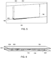
- FIG. 5 is a detail isometric view of first antenna 136 and second antenna 138 as shown in FIG. 4 .
- Fixture 402 is coupled to interior wall 302 of block 112.
- fixture 402 is coupled to interior wall 302 using one or more of fasteners, adhesives, welding, and other components or techniques.
- fixture 402 is an integral component of block 112.
- fixture 402 and block 112 are formed in a casting process.
- First antenna 136 is coupled to fixture 402 and is positioned above second antenna 138, separated by air gap distance 404.
- Second antenna 138 is coupled to piston rod 106.
- Second antenna 138 has a length half of the length of first antenna 136.
- First antenna 136 and second antenna 138 have the same width and height. Both first antenna 136 and second antenna 138 are microstrip antennas.
- Fixture 402 has a width and length equal to the width and length of first antenna 136.
- first antenna 136, and second antenna 138 have different sizes, geometries, configurations, or other characteristics.
- second antenna 138 may have a length equal to that of first antenna 136, a length less than half of that of first antenna 136, or a length greater than that of first antenna 136.
- Second antenna 138 may have a width greater or less than that of first antenna 136.
- fixture 402 may have dimensions other than those of first antenna 136.
- FIG. 6 is a further detail view of first antenna 136 and second antenna 138 shown in FIG. 4 and FIG. 5 .
- Second antenna 138 is a meander line microstrip antenna included on substrate 602.
- RF sensor 140 is positioned substantially at the center of substrate 602 with second antenna 138 positioned on at least two sides of RF sensor 140.
- Second antenna 138 includes a plurality of width segments 604 and a plurality of length segments 606.
- Width segments 604 run substantially the width of substrate 602. Successive width segments 604 decrease in size as they are located closer to RF sensor 140.
- Length segments 606 run along the length of substrate 602. Width segments 604 and length segments 606 provide greater electromagnetic discontinuity that provides more energy in electromagnetic radiation.
- First antenna 136 is also a meander line microstrip antenna having the same or similar configuration as that of second antenna 138.
- first antenna 136 does not have successive width segments 604 that decrease in size as they approach the center of first antenna 136. Rather, successive width segments are substantially identical as first antenna 136 is not coupled to RF sensor 140.
- first antenna 136 is a microstrip antenna but not a meander line microstrip antenna.
- first antenna 136 is an antenna type other than microstrip. For example, and without limitation, first antenna 136 is a monopole antenna.
- Air gap distance 404 separates first antenna 136 and second antenna 138. Air gap distance 404 allows second antenna 138 and piston rod 106 (shown in FIG. 4 ) to which second antenna 138 is coupled to travel relative to first antenna 136 and fixture 402 (shown in FIG. 4 ) without physical contact. Air gap distance 404 is greater than 0 millimeters (mm). Fixture 402 is one or more of sized and positioned such that air gap distance 404 is between and inclusive of 5 millimeters (mm) and 20 mm. Increasing air gap distance 404 provides for greater clearance and design flexibility for components of reciprocating system 100 and piston rod monitoring system 101. The configuration of first antenna 136 and second antenna 138, as described herein, allows for air gap distance 404 to be increased while maintaining communication between first antenna 136 and second antenna 138.
- the electrical output signal from second antenna 138, received at first antenna 136 decreases in magnitude relative to the electrical input signal.
- the electrical output signal is transmitted by second antenna 138 in response to receiving the electrical input signal transmitted from first antenna 136.
- the decrease in magnitude of the electrical output signal as air gap distance 404 increases constrains the air gap distance to a value at which the received electrical output signal has a sufficient magnitude to be processed by interrogator 204 (shown in FIG. 2 ).
- Air gap distance 404 is limited to a value at which first antenna 136 and second antenna 138 are able to communicate.
- first antenna 136 and second antenna 138 increases the maximum value of air gap distance 404 at which the received electrical output signal maintains sufficient magnitude for processing by interrogator 204.
- use of a meander line microstrip antenna for second antenna 138 improves coupling in comparison to a straight line microstrip antenna.
- a meander line microstrip antenna operating between and inclusive of 400 megahertz and 450 megahertz, the magnitude of the received electrical output signal is between and inclusive of approximately -10 decibels (dB) and approximately -12 decibels dB relative to the electrical input signal when air gap distance 404 is 5 millimeters (mm). Between and inclusive of 400 megahertz and 450 megahertz, the magnitude of the received electrical output signal is between and inclusive of approximately -16 dB and approximately -17 dB relative to the electrical input signal when air gap distance 404 is 10 mm.
- the magnitude of the received electrical output signal is between and inclusive of approximately -19 dB and approximately -20 dB relative to the electrical input signal when air gap distance 404 is 15 mm.
- the magnitude of the received electrical output signal is between and inclusive of approximately -22 dB and approximately -24 dB relative to the electrical input signal when air gap distance 404 is 20 mm.
- Interrogator 204 operates with an electrical output signal having a magnitude of between 0 dB and -30 dB relative to the electrical input signal.
- Using a meander line microstrip second antenna 138 allows for interrogator 204 to operate with an air gap distance 404 of 20 mm, as the resulting electrical output signal has a magnitude of approximately between -22 dB and -24 dB relative to the electrical input signal. This is within the range of operation of interrogator 204.
- a straight microstrip second antenna 138 allows for an air gap distance 404 of between 6 mm and 8 mm to provide for an electrical output signal with a magnitude of no less than -30 dB relative to the electrical input signal as required by interrogator 204. Therefore, use of at least one meander line microstrip antenna allows for a greater air gap distance 404 that in turn allows for greater clearance between components of reciprocating system 100 and greater design flexibility of piston rod monitoring system 101.
- FIG. 7 is a schematic view of piston rod monitoring system 101 shown in FIG. 1 with second antenna 138 and RF sensor 140 embedded in piston rod 106.
- Second antenna 138 is positioned below first antenna 136 coupled to fixture 402.
- Second antenna 138 is embedded in piston rod 106.
- material is removed from piston rod 106 to form a depression. Material is removed, for example, and without limitation, using a surface mill or other machining technique.
- Second antenna 138 is disposed within the depression and coupled to piston rod 106, e.g., and without limitation using an adhesive.
- second antenna 138 is sealed by backfilling the depression with, for example, and without limitation, an epoxy, polymer, or other substance.
- second antenna is an all-quartz-package and is coupled to piston rod 106.
- RF sensor 140 is coupled to second antenna 138, for example, and without limitation, with a wired connection 702.
- RF sensor 140 is coupled to piston rod 106 at a location remote from second antenna 138.
- RF sensor 140 is attached to the surface of piston rod 106.
- RF sensor 140 is embedded in piston rod 106 as described with respect to second antenna 138.
- RF sensor 140 may be an all-quartz-package.
- RF sensor 140 is positioned substantially in the middle of second antenna 138 as described with reference to FIG. 6 .
- RF sensor 140 and second antenna 138 are embedded in piston rod 106.
- the combination of RF sensor 140 and second antenna 138 is a single all-quartz-package.
- FIG. 8 is a schematic view of piston rod monitoring system shown 101 in FIG. 1 with second antenna 138 coupled to piston rod 106 by a sleeve 802.
- RF sensor 140 and second antenna 138 are coupled to sleeve 802 as described with reference to FIG. 7 , e.g., and without limitation by adhesives, embedded in sleeve 802, or otherwise coupled to sleeve 802.
- a single all-quartz-package including second antenna 138 and RF sensor 140 positioned substantially in the middle of second antenna 138 is coupled to sleeve 802.
- Sleeve 802 is coupled to piston rod 106 at a position below first antenna 136 and fixture 402.
- sleeve 802 is slid onto piston rod 106 during assembly of reciprocating system 100.
- Sleeve 802 is secured to piston rod 106 by an interference fit with piston rod 106, an adhesive, fasteners, or other components or techniques.
- sleeve 802 includes two or more pieces and sleeve 802 is assembled around piston rod 106.
- the two pieces are secured to each other by adhesive, fasteners, or other components or techniques.
- Sleeve 802, itself, is coupled to piston rod 106 by an interference fit with piston rod 106, an adhesive, fasteners, or other components or techniques.
- FIG. 9 is a schematic view of the piston rod monitoring system 101 shown in FIG. 1 with second antenna 138 coupled to piston rod 106, including a first portion 902 and a second portion 904, by a joining portion 906.
- RF sensor 140 and second antenna 138 are coupled to joining portion 906 as described with reference to FIG. 7 , e.g., and without limitation by adhesives, embedded in joining portion 906, or otherwise coupled to joining portion 906.
- a single all-quartz-package including second antenna 138 and RF sensor 140 positioned substantially in the middle of second antenna 138 is coupled to joining portion 906.
- Joining portion 906 is coupled to piston rod 106 at a position below first antenna 136 and fixture 402.
- Joining portion 906 is coupled to both first portion 902 and second portion 904 of piston rod 106. In some embodiments, joining portion 906 extends within both first portion 902 and second portion 904. Joining portion 906 is secured to first portion 902 and second portion 904 using, for example, and without limitation, joining portion 906 includes a key and first portion 902 and second portion 904 both include a keyway. In alternative embodiments, joining portion 906 is coupled to first portion 902 and second portion 904 by an interference fit with first portion 902 and second portion 904, an adhesive, fasteners, or other components or techniques. In further alternative embodiments, joining portion 906 does not extend within first portion 902 and second portion 904. In some embodiments, joining portion 906 is coupled to first portion 902 and second portion 904 by welding, an adhesive, fasteners, or other components or techniques.
- the above-described system provides for enhanced monitoring of a piston rod of a reciprocating system.
- the method and systems described herein allow for enhanced monitoring of a piston rod using an RF sensor such as an acoustic wave sensor.
- the acoustic wave sensor is an all-quartz-package, increasing the lifetime of the RF sensor positioned within the reciprocating system by encapsulating the RF sensor.
- the systems and methods described herein facilitate monitoring of a piston rod and increasing the lifetime of a monitoring system, as the RF sensor is powered by an electrical input signal transmitted wirelessly from an interrogator rather than by a battery.
- the systems and methods described herein facilitate monitoring of a piston rod in translation during operation of the piston rod.
- an operating lifetime of a reciprocating system can be increased by replacing monitored piston rods prior to a significant reduction in service life of the piston rod that may also reduce the service life of other components of the reciprocating system. Additionally, operating conditions of the reciprocating system can be changed based on monitoring of the piston rod to reduce loads on the piston rod or otherwise increase operational life of the piston rod.
- the operating conditions of the reciprocating system that are controllable include crankshaft rotational speed, pressure within the cylinder, gas volume provided to the cylinder, or other operating conditions.
- An exemplary technical effect of the methods, systems, and apparatus described herein includes at least one of: (a) monitoring a characteristic of a piston rod using an acoustic wave sensor; (b) wirelessly interrogating the acoustic wave sensor using an interrogator that transmits an electronic input signal; (c) generating an mechanical surface wave from the electronic input signal using the acoustic wave sensor; (d) generating an electronic output signal from the mechanical surface wave using the acoustic wave sensor; (e) transmitting the electronic output signal to the interrogator; and (f) determining a characteristic related to the piston rod based on the electronic output signal and using the interrogator.
- Exemplary embodiments of method and systems for monitoring a piston rod are described above in detail.
- the method and systems described herein are not limited to the specific embodiments described herein, but rather, components of systems or steps of the methods may be utilized independently and separately from other components or steps described herein.
- the systems and methods may also be used in combination with other mechanical system components, and are not limited to practice with only piston rods as described herein. Rather, the exemplary embodiments may be implemented and utilized in connection with many other components that move at least in part in translation such as pistons, connecting rods, or other components.
- Such devices typically include a processor, processing device, or controller, such as a general purpose central processing unit (CPU), a graphics processing unit (GPU), a microcontroller, a reduced instruction set computer (RISC) processor, an application specific integrated circuit (ASIC), a programmable logic circuit (PLC), a field programmable gate array (FPGA), a digital signal processing (DSP) device, and/or any other circuit or processing device capable of executing the functions described herein.
- the methods described herein may be encoded as executable instructions embodied in a computer readable medium, including, without limitation, a storage device and/or a memory device. Such instructions, when executed by a processing device, cause the processing device to perform at least a portion of the methods described herein.
- the above examples are exemplary only, and thus are not intended to limit in any way the definition and/or meaning of the term processor and processing device.
Landscapes
- Engineering & Computer Science (AREA)
- Mechanical Engineering (AREA)
- General Engineering & Computer Science (AREA)
- Physics & Mathematics (AREA)
- Computer Networks & Wireless Communication (AREA)
- General Physics & Mathematics (AREA)
- Chemical & Material Sciences (AREA)
- Combustion & Propulsion (AREA)
- Electromagnetism (AREA)
- Signal Processing (AREA)
- Arrangements For Transmission Of Measured Signals (AREA)
Abstract
Description
- The field of the disclosure relates generally to reciprocating systems and, more particularly, to a system for measuring conditions related to a piston rod.
- Reciprocating systems typically include a reciprocating piston that moves axially within a cylinder and is either driven by or drives a piston rod coupled to the piston. Reciprocating systems include, for example, and without limitation, reciprocating engines, reciprocating gas compressors, integral reciprocating gas engine-compressors, i.e., motocompressors, and other reciprocating systems. In reciprocating compressors, the piston rod is coupled to a crankshaft such that rotational movement of the crankshaft, as powered by an engine or motor, is transformed into axial movement of the piston rod and piston coupled to the piston rod. The axial movement of the piston compresses gas within the cylinder. In reciprocating engines, a combustion chamber is in fluid communication with the piston and drives the piston. The piston is coupled to a piston rod moved axially by the piston. The piston rod is coupled to a crankshaft by a crosshead assembly and a connecting rod. Axial movement of the piston rod is transformed in rotational movement of the crankshaft by the geometry of the connection between the piston rod and the crankshaft provided by the connecting rod. As the piston rod experiences operational cycles fatigue loads, e.g., alternating or oscillation loads, occur in the piston rod which may result in outage of the reciprocating system. In the absence of a system to measure conditions related to the piston rod, outages of the reciprocating system may be unexpected and result in unplanned expense. Furthermore, in the absence of a system to directly measure conditions related to the piston rod, a reciprocating system cannot be accurately controlled to reduce fatigue loads or other loads on the piston rod. This limits the ability to increase the operational lifecycle of the reciprocating system and reduce unplanned outages through control of the operating conditions of the reciprocating system.
- In one aspect, a sensor system for determining a condition of a piston rod of a reciprocating system is provided. The sensor system includes an interrogator system having a first antenna. The sensor system further includes a second antenna separated from the first antenna by an air gap distance. The second antenna is configured to be coupled to the piston rod of the reciprocating system. The second antenna is a patch antenna and is configured to communicate with the first antenna through a range of translational movement relative to the first antenna. The sensor system further includes a radio frequency sensor coupled to the second antenna. The radio frequency sensor is configured to be coupled to the piston rod of the reciprocating system, measure a characteristic associated with the piston rod of the reciprocating system, and transmit, through the second antenna, data associated with the characteristic to the first antenna of the interrogator system.
- In a further aspect, a reciprocating system is provided. The reciprocating system includes a piston rod including a first end and a second end opposite the first end. A piston rod is coupled to the second end. The reciprocating system further includes a block. The piston rod extends at least partially through the block. The reciprocating system includes a sensor system for measuring a characteristic associated with the piston rod. The sensor system includes an interrogator system including a first antenna. The first antenna is coupled to an interior surface of the block. The sensor system further includes a second antenna separated from the first antenna by an air gap distance. The second antenna is coupled to the piston rod. The second antenna is a patch antenna and is configured to communicate with the first antenna through a range of translational movement relative to the first antenna. The sensor system further includes a surface acoustic wave sensor coupled to the second antenna and coupled to the piston rod. The surface acoustic wave sensor is configured to measure a strain associated with the piston rod and transmit data associated with the strain to the first antenna of the interrogator system through the second antenna.
- These and other features, aspects, and advantages of the present disclosure will become better understood when the following detailed description is read with reference to the accompanying drawings in which like characters represent like parts throughout the drawings, wherein:
-
FIG. 1 is a schematic, cross-sectional view of a portion of an exemplary reciprocating system including an exemplary piston rod monitoring system; -
FIG. 2 is a block diagram of the piston rod monitoring system shown inFIG. 1 ; -
FIG. 3 is a schematic view of an exemplary first antenna and an exemplary second antenna that may be used with the piston rod monitoring system shown inFIG. 1 ; -
FIG. 4 is a schematic view of an alternative first antenna and an alternative second antenna that may be used with the piston rod monitoring system shown inFIG. 1 ; -
FIG. 5 is a detail isometric view of the alternative first antenna and alternative second antenna shown inFIG. 4 ; -
FIG. 6 is a further detail view of the alternative first antenna and alternative second antenna shown inFIG. 4 ; -
FIG. 7 is a schematic view of the piston rod monitoring system shown inFIG. 1 embedded in the piston rod shown inFIG. 1 ; -
FIG. 8 is a schematic view of the piston rod monitoring system shown inFIG. 1 coupled to the piston rod shown inFIG. 1 by an exemplary sleeve; and -
FIG. 9 is a schematic view of the piston rod monitoring system shown inFIG. 1 coupled to the piston rod shown inFIG. 1 by an exemplary joining portion. - Unless otherwise indicated, the drawings provided herein are meant to illustrate features of embodiments of this disclosure. These features are believed to be applicable in a wide variety of systems comprising one or more embodiments of this disclosure. As such, the drawings are not meant to include all conventional features known by those of ordinary skill in the art to be required for the practice of the embodiments disclosed herein.
- In the following specification and the claims, reference will be made to a number of terms, which shall be defined to have the following meanings.
- The singular forms "a", "an", and "the" include plural references unless the context clearly dictates otherwise.
- "Optional" or "optionally" means that the subsequently described event or circumstance may or may not occur, and that the description includes instances where the event occurs and instances where it does not.
- Approximating language, as used herein throughout the specification and claims, may be applied to modify any quantitative representation that could permissibly vary without resulting in a change in the basic function to which it is related. Accordingly, a value modified by a term or terms, such as "about", "approximately", and "substantially", are not to be limited to the precise value specified. In at least some instances, the approximating language may correspond to the precision of an instrument for measuring the value. Here and throughout the specification and claims, range limitations may be combined and/or interchanged, such ranges are identified and include all the sub-ranges contained therein unless context or language indicates otherwise.
- As used herein, the terms "processor" and "computer" and related terms, e.g., "processing device", "computing device", and "controller" are not limited to just those integrated circuits referred to in the art as a computer, but broadly refers to a microcontroller, a microcomputer, a programmable logic controller (PLC), an application specific integrated circuit, and other programmable circuits, and these terms are used interchangeably herein. In the embodiments described herein, memory may include, but is not limited to, a computer-readable medium, such as a random access memory (RAM), and a computer-readable non-volatile medium, such as flash memory.
- Alternatively, a floppy disk, a compact disc - read only memory (CD-ROM), a magneto-optical disk (MOD), and/or a digital versatile disc (DVD) may also be used. Also, in the embodiments described herein, additional input channels may be, but are not limited to, computer peripherals associated with an operator interface such as a mouse and a keyboard. Alternatively, other computer peripherals may also be used that may include, for example, but not be limited to, a scanner. Furthermore, in the exemplary embodiment, additional output channels may include, but not be limited to, an operator interface monitor.
- Further, as used herein, the terms "software" and "firmware" are interchangeable, and include any computer program stored in memory for execution by personal computers, workstations, clients and servers.
- As used herein, the term "non-transitory computer-readable media" is intended to be representative of any tangible computer-based device implemented in any method or technology for short-term and long-term storage of information, such as, computer-readable instructions, data structures, program modules and sub-modules, or other data in any device. Therefore, the methods described herein may be encoded as executable instructions embodied in a tangible, non-transitory, computer readable medium, including, without limitation, a storage device and a memory device. Such instructions, when executed by a processor, cause the processor to perform at least a portion of the methods described herein. Moreover, as used herein, the term "non-transitory computer-readable media" includes all tangible, computer-readable media, including, without limitation, non-transitory computer storage devices, including, without limitation, volatile and nonvolatile media, and removable and non-removable media such as a firmware, physical and virtual storage, CD-ROMs, DVDs, and any other digital source such as a network or the Internet, as well as yet to be developed digital means, with the sole exception being a transitory, propagating signal.
- The piston rod monitoring systems described herein provide for enhanced monitoring of a piston rod of a reciprocating system. Enhanced monitoring of a characteristic such as strain on the piston rod provides an ability to determine the condition of the piston rod such as a load on the piston rod, a stress of the piston rod, or other condition. For example, and without limitation, the monitoring system described herein or a system in communication with the monitoring system determines the condition of the piston rod based on the monitored characteristic, e.g., calculating a stress on the piston rod from a measured strain and using the geometry of the piston rod. The condition of the piston rod can include for example, and without limitation, that the piston rod is in normal condition. Monitoring of the piston rod further provides for a determination that the piston rod is not in normal condition. For example, and without limitation, the piston rod may be in a forecasted significant reduction in service life condition indicating that servicing of the piston rod or the reciprocating system is recommended to prevent or reduce the likelihood of a significant reduction in service life of the piston rod. The normal or other condition is determined, for example, and without limitation, by the piston rod monitoring system or a system in communication with the piston rod monitoring system based on one or more measured characteristics and determined conditions, e.g., the piston rod is determined to be in a normal condition if a stress calculated from a measured strain is below a predetermined threshold. Monitoring of the piston rod using the systems and methods described herein may reduce unexpected reductions in service life of one or more of the piston rod and other components of the reciprocating system.
-
FIG. 1 is a schematic, cross-sectional view of a portion of anexemplary reciprocating system 100 including a pistonrod monitoring system 101. Pistonrod monitoring system 101 is a sensor system for measuring a characteristic associated withreciprocating system 100. For example, and without limitation, pistonrod monitoring system 101 measures strain of a piston rod in reciprocatingsystem 100, a temperature, a pressure of the environment around the piston rod, piston rod deflection, torque on the piston rod, bending of the piston rod, vibration of the piston rod, or other characteristics ofreciprocating system 100. Pistonrod monitoring system 101 is used or is configured to determine a condition of the piston rod. For example, and without limitation, pistonrod monitoring system 101 determines piston rod load by directly measuring strain of the piston rod and determining the piston rod load based on the measured strain and the characteristics of the piston rod including, for example, and without limitation, Young's modulus and the geometry of the piston rod such as the cross sectional area of the piston rod. -
Reciprocating system 100 is a mechanical system including at least one portion that moves in translation and at least a second portion that moves in rotation. The rotational part drives the translational part, or the translational part drives the rotational part. For example, and without limitation,reciprocating system 100 is or includes a reciprocating engine, a reciprocating compressor, reciprocating pump, a motocompressor, hyper-compressors, fracturing pumps, e.g., for use in hydraulic fracturing, or other reciprocating system.Reciprocating system 100 includes acylinder head 102 and apiston 103 disposed within acylinder 104 defined withincylinder head 102. For example, and without limitation,cylinder head 102 is one or more of a cast and machined structure which defines acavity forming cylinder 104.Cylinder head 102 includes one or more ports, channels, or other cavities defined by the structure ofcylinder head 102. In some embodiments, the ports, channels, or other cavities ofcylinder head 102 provide one or more compressor inlets and one or more compressor outlets. Aspiston 103 is driven, it draws one or more gasses intocylinder 104 through the compressor inlet(s), compresses the one or more gasses, and expels the compressed one or more gasses through the compressor outlet(s).Cylinder head 102 and the one or more ports, channels, or other cavities are configured for either single acting compression, i.e., gas is compressed only on one side ofpiston 103, or double acting compression, i.e., gas is alternatingly compressed on both sides ofpiston 103. - In alternative embodiments, the ports, channels, or other cavities provide fuel and air into
cylinder 104 and evacuate exhaust fromcylinder 104.Cylinder 104 provides a combustion chamber formed by atop portion 107 ofcylinder head 102,cylinder 104, andpiston 103. Combustion of the fuel and oxygen drivespiston 103 axially withincylinder 104 during a power stroke ofreciprocating system 100.Piston 103 is driven away fromtop portion 107. In a compression stroke,piston 103 travels towardtop portion 107. In some embodiments,reciprocating system 100 is a four stroke engine including an intake stroke, the compression stroke, power stroke, and an exhaust stroke. In alternative embodiments,reciprocating system 100 is a two stroke engine. -
Piston 103 is coupled topiston rod 106. For example, and without limitation,piston 103 is coupled topiston rod 106 by one or more fasteners, e.g., a nut, a weld, orpiston 103 andpiston rod 106 are formed, e.g., cast or machined, as a single component.Piston rod 106 extends through afirst chamber 108 and asecond chamber 110.First chamber 108 is a portion ofblock 112 and defines a cavity through whichpiston rod 106 extends.Second chamber 110 is a portion ofblock 112 and defines a further cavity through whichpiston rod 106 extends. In alternative embodiments, at least one offirst chamber 108 andsecond chamber 110 are separable fromblock 112 and are coupled to block 112, for example, and without limitation, by fasteners such as bolts.Piston rod 106 further extends within an additional cavity defined byblock 112.Piston rod 106 is coupled tocrosshead assembly 114.Piston rod 106 is coupled to one end ofcrosshead assembly 114, for example, and without limitation, by fasteners such as bolts. The opposite end ofcrosshead assembly 114 is coupled to connectingrod 116 bywrist pin 118.Connecting rod 116 is coupled by bearingcap 120 to a crankthrow 124 ofcrankshaft 122.Connecting rod 116 andbearing cap 120 form a journal bearing or other type ofbearing in contact withcrankshaft 122.Crankshaft 122 is contained withincrankcase 126. For example, and without limitation,crankshaft 122 is supported withincrankcase 126 by main bearings such as journal bearings. -
Reciprocating system 100 further includes afirst seal 128 and asecond seal 130.First seal 128 andsecond seal 130 form seals withfirst chamber 108 andsecond chamber 110, respectively. First seal 128 seals with afirst seat 132 to sealfirst chamber 108.Second seal 130 seals with asecond seat 134 to sealsecond chamber 110.First chamber 108 andsecond chamber 110, along withfirst seal 128 andsecond seal 130, provide separation betweencylinder 104 and other components ofreciprocating system 100 including, for example, and without limitation,crosshead assembly 114, connectingrod 116, andcrankshaft 122. A cylinder packing 135further seals cylinder 104.Piston rod 106 passes through cylinder packing 135, and cylinder packing 135 forms a seal such that gasses withincylinder 104 are substantially prevented from exitingcylinder 104. Gasses that pass through cylinder packing 135 are prevented from entering other areas ofreciprocating system 100 byfirst chamber 108 and/orsecond chamber 110 and their respective seals,first seal 128 andsecond seal 130. For example, and without limitation, one or more offirst chamber 108 andsecond chamber 110 prevent combustion gasses or other material from exitingcylinder 104 and entering other areas ofreciprocating system 100. In some embodiments,reciprocating system 100 only includes bothfirst chamber 108 andsecond chamber 110 in applications where hazardous gasses are present. When hazardous gasses are not present,reciprocating system 100 only includessecond chamber 110 and does not includefirst chamber 108. For example, and without limitation, hazardous gasses include hydrogen and hydrogen sulfide. In some embodiments, one or more offirst chamber 108 andsecond chamber 110 along with one or more offirst seal 128 andsecond seal 130 prevent or reduce oil or other lubricants from enteringcylinder 104 from other portions of reciprocatingsystem 100. - Piston
rod monitoring system 101 is disposed, at least partially, within reciprocatingsystem 100. For example, and without limitation, pistonrod monitoring system 101 is disposed withinfirst chamber 108. In alternative embodiments, pistonrod monitoring system 100 is disposed withinsecond chamber 110 or elsewhere withinblock 112. - Piston
rod monitoring system 101 includes afirst antenna 136 in radiofrequency communication with asecond antenna 138.Second antenna 138 is coupled to a radiofrequency (RF)sensor 140.Second antenna 138 andRF sensor 140 are coupled topiston rod 106.RF sensor 140 is a sensor that measures a characteristic related topiston rod 106 and transmits information throughsecond antenna 138. For example, and without limitation, the location ofRF sensor 140 onpiston rod 106 provides for direct measurement of piston rod strain, and piston rod load calculated from piston rod strain, with increased accuracy in comparison to piston rod load measuring by other systems or methods such as indirectly obtaining piston rod load through gas loads and inertia forces. In some embodiments,RF sensor 140 is a surface acoustic wave sensor.RF sensor 140 may be an all-quartz-package sensor, i.e., a sensor sealed between a quartz substrate and a second quartz layer. In alternative embodiments,RF sensor 140 is another type of sensor. For example, and without limitation,RF sensor 140 is a strain gauge, temperature sensor, e.g., a thermocouple, accelerometer, or gyroscope.RF sensor 140 is a microelectromechanical system (MEMS) sensor. -
FIG. 2 is a block diagram of pistonrod monitoring system 101. Pistonrod monitoring system 101 includesRF sensor 140 coupled topiston rod 106 for measuring a characteristic ofpiston rod 106.RF sensor 140 is coupled tosecond antenna 138 for input toRF sensor 140 and output fromRF sensor 140. In some embodiments,RF sensor 140 is coupled to an electrical over-stress (EOS) andimpedance matching circuit 202 positioned betweenRF sensor 140 andsecond antenna 138. EOS andimpedance matching circuit 202 enhances power transmission and coupling betweenfirst antenna 136 andsecond antenna 138. In alternative embodiments,RF sensor 140 is coupled directly tosecond antenna 138.Second antenna 138 is in RF communication withfirst antenna 136.First antenna 136 is coupled tointerrogator 204 by firstcoaxial wiring 206, acoaxial connector 208, and secondcoaxial wiring 210.Interrogator 204 interrogatesRF sensor 140 by providing RF energy throughfirst antenna 136 tosecond antenna 138 coupled toRF sensor 140.Interrogator 204 further receives information fromRF sensor 140, transmitted bysecond antenna 138, usingfirst antenna 136.Interrogator 204 includesmultiplexor 212 andsensor reading module 214.Multiplexor 212 facilitates collection of information fromRF sensor 140 andsensor reading module 214 analyzes or otherwise processes the information received fromRF sensor 140.Interrogator 204, or a subset of components thereof, forms a data acquisition system coupled to one or more offirst antenna 136 and coupled to a computing device. - In one embodiment,
RF sensor 140 is a surface acoustic wave sensor. For example, and without limitation,RF sensor 140 includes a piezoelectric substrate (not shown), a first interdigitated transducer (IDT) (not shown) coupled to the piezoelectric substrate, and a second IDT (not shown) coupled to the piezoelectric substrate and separated from the first IDT by a delay line region (not shown). The first IDT receives an electrical input signal and produces an acoustic wave, e.g., a surface mechanical wave. The second IDT converts the acoustic wave to an electrical output signal through the piezoelectric effect. The characteristics of the surface on whichRF sensor 140 is coupled affect the surface mechanical wave produced byRF sensor 140. For example, and without limitation, pressure, strain, torque, temperature, or other characteristics or environmental conditions affectingpiston rod 106 change one or more of the length of the delay line region and the spacing between interdigitated electrodes of the first IDT and the second IDT. The electrical output signal generated by the second IDT from the surface mechanical wave is analyzed to determine characteristics of the electrical output signal such as, for example, and without limitation, phase-shift, frequency-shift, or time-delay. The electrical output signal is analyzed bysensor reading module 214 to determine the mechanical characteristics or other characteristics ofpiston rod 106. -
RF sensor 140 receives electromagnetic energy fromsecond antenna 138 and EOS andimpedance matching circuit 202. EOS andimpedance matching circuit 202 enhances power transmission and coupling betweenfirst antenna 136 andsecond antenna 138. In response to receiving electromagnetic energy, e.g., and without limitation, in the radio frequency spectrum,second antenna 138 provides energy toRF sensor 140.RF sensor 140 uses the received energy to generate the surface mechanical wave using the first IDT. The second IDT converts the surface mechanical wave to the electrical output signal which is transmitted bysecond antenna 138. -
First antenna 136 receives the electrical output signal transmitted bysecond antenna 138.Second antenna 138 is coupled topiston rod 106 andfirst antenna 136 is coupled to block 112 infirst chamber 108.First antenna 136 is coupled tocoaxial wiring 206 that extends at least partially thoughblock 112.Coaxial wiring 206 is coupled tocoaxial connector 208 which is coupled to or extends partially throughblock 112.Coaxial connector 208 is coupled tocoaxial wiring 210 which coupled tointerrogator 204.Coaxial wiring 210,coaxial connector 208, andcoaxial wiring 206 couplefirst antenna 136 tointerrogator 204 and provide for communication of power, the electrical input signal, and the electrical output signal. -
Interrogator 204 interrogatesRF sensor 140 by generating the electrical input signal and transmitting the electrical input signal through coaxial wiring,coaxial connector 208,coaxial wiring 206, andfirst antenna 136.First antenna 136 transmits the electrical input signal as RF electromagnetic energy.Second antenna 138 receives the RF electromagnetic energy transmitted byfirst antenna 136 and provides the electrical input signal toRF sensor 140.RF sensor 140 uses the electrical input signal received during interrogation to generate the surface mechanical wave and generates the electrical output signal from the surface mechanical wave in response to the electrical input signal.RF sensor 140 provides the electrical output signal tosecond antenna 138.Second antenna 138 transmits the electrical output signal as RF electromagnetic energy that is received byfirst antenna 136. This occurs in response to the interrogation byinterrogator 204.First antenna 136 provides the received electrical output signal tointerrogator 204 throughcoaxial wiring 206,coaxial connector 208, andcoaxial wiring 210. -
Interrogator 204 includesMUX 212 andsensor reading module 214.MUX 212 multiplexes one or more of the electrical input signals and the electrical output signals.Sensor reading module 214 processes the electrical output signal to determine one or more characteristics associated with a component measured byRF sensor 140, e.g., and without limitation,piston rod 106. For example, and without limitation,sensor reading module 214 is or is included in one or more computing devices and maybe implemented by a combination of one or more of software and hardware components. Software components include one or more of programs, application, processor executable code, modules, and other software components. Hardware components include memory devices such as volatile or non-volatile memory, random access memory, a hard drive, flash memory, or other hardware for storing information. Hardware components include processing devices such as a processor, a field programmable gate array, a programmable logic controller, or other hardware for processing one or more of instructions and information stored in memory or received. Hardware components may further input/output devices such as serial ports, Universal Serial Bus port, mouse, keyboard, display, or other input/output hardware. -
Sensor reading module 214 determines, for example, and without limitation, strain ofpiston rod 106 from the electrical output signal using a calibration curve, function, equation, or formula that relates a property of the electrical output signal to strain. For example, and without limitation, the property of the electrical output signal is a phase-shift between the electrical input signal and the electrical output signal, a frequency-shift between the electrical input signal and the electrical output signal, or a time delay between the electrical input signal and the electrical output signal. In some embodiments,sensor reading module 214 can measure other characteristics such as temperature, torque, or pressure.Sensor reading module 214 determines a condition ofpiston rod 106. For example, and without limitation,sensor reading module 214 determines the piston rod load using a calibration curve, function, equation, or other formula that relates strain to load, e.g., and without limitation, calculating load from strain, a known Young's modulus, and a known cross-sectional area ofpiston rod 106. In further embodiments,sensor reading module 214 determines a condition ofpiston rod 106 including whetherpiston rod 106 is in a normal condition or is not in normal condition such as a forecasted significant reduction in service life condition.Sensor reading module 214 determines the condition, normal or not normal, based on a measured characteristic, e.g., strain, or a determined condition, e.g., stress or load. For example, and without limitation,sensor reading module 214 determines thatpiston rod 106 is in a normal condition by comparing a stress ofpiston rod 106, determined from a measured strain characteristic, to a predetermined threshold value and determining that the stress ofpiston rod 106 is less than the predetermined threshold value. - In alternative embodiments, piston
rod monitoring system 101 includesinterrogator 204 andRF sensor 140 in communication withinterrogator 204.Interrogator 204 is passive and receives electrical output signal fromRF sensor 140 throughfirst antenna 136 andsecond antenna 138.RF sensor 140 includes a power source or is coupled to a power source also coupled topiston rod 106. For example, and without limitation,RF sensor 140 is coupled to a battery. In further alternative embodiments, one or more components ofinterrogator 204 are included in a computing device. For example, and without limitation,sensor reading module 214 is a program stored in memory and executed by a processor of a computing device. The computing device is coupled to aseparate MUX 212 by a wired or wireless connection. Alternatively,interrogator 204 is an application specific integrated circuit that interrogatesRF sensor 140.Interrogator 204 provides an output, e.g., and without limitation, a determined piston rod load or other condition, through a wired or wireless connection to a separate computing device. -
FIG. 3 is a schematic view offirst antenna 136 andsecond antenna 138 of pistonrod monitoring system 101.First antenna 136 andsecond antenna 138 are in wireless communication, e.g., and without limitation, through transmission and reception of RF electromagnetic energy.Second antenna 138 is coupled topiston rod 106 and RF sensor 140 (shown inFIG. 2 ). In the exemplary embodiment,second antenna 138 is a microstrip antenna or microstrip coupler. For example, and without limitation,second antenna 138 is narrow band, wide-beam patch antenna, i.e., an antenna with a significantly greater width and length in comparison to height and a metallic antenna portion mounted to a ground plane, or other printed antenna. In some embodiments,second antenna 138 is a meander line microstrip antenna (shown inFIG. 6 ). As used herein, a meander line microstrip antenna is a patch antenna including, at least, conductive material such as a wire structure in a meander-line section. In the meander-line section, the conductive material is positioned as at least two sections running the width of the antenna coupled by a section running the length of the antenna. The conductive material is folded, bent, etched, or otherwise formed to create 90 degree turns that form the width sections and length sections. The overall length of the meander line microstrip antenna has a length less than the total pre-folded length of the conductive material. - Also, in the exemplary embodiment,
first antenna 136 is a monopole antenna coupled to aninterior wall 302 ofblock 112.First antenna 136 andsecond antenna 138 are positioned withinfirst chamber 108 ofreciprocating system 100.First antenna 136 is coupled tointerrogator 204 by coaxial wiring 206 (shown inFIG. 2 ), coaxial connector 208 (shown inFIG. 2 ), andcoaxial wiring 210. - In operation,
piston rod 106 moves in translation relative to block 112 as piston 103 (shown inFIG. 1 ) and crankshaft 122 (shown inFIG. 1 )drive piston rod 106. Translation ofpiston rod 106 results in translation ofsecond antenna 138, coupled topiston rod 106, relative tofirst antenna 136.First antenna 136 andsecond antenna 138 communicate such that translation ofsecond antenna 138 relative tofirst antenna 136 does not substantially interfere with communication betweenfirst antenna 136 andsecond antenna 138.Second antenna 138 is configured, as described herein, to communicate withfirst antenna 136 through the range of translational movement relative tofirst antenna 136. For example, and without limitation, the properties of one or more offirst antenna 136 andsecond antenna 138 allow for communication at any point in the range of translation ofsecond antenna 138, e.g., and without limitation,second antenna 138 has a range of translation equal to the stroke ofpiston 103, 200 millimeters (mm) plus or minus 100 mm. In alternative embodiments, the stroke ofpiston 103 is greater or less than 200 mm. Properties offirst antenna 136 andsecond antenna 138 include, for example, and without limitation, antenna type, antenna geometry, beam pattern, gain, directivity, bandwidth, air gap distance betweenfirst antenna 136 andsecond antenna 138, or other characteristics. Stationary antennas or relatively stationary antennas, e.g., where one antenna is in rotational movement but is substantially stationary along a longitudinal axis relative to the other antenna, do not face the same difficulties maintaining communication as in an antenna system where one antenna is in translational movement relative to the antenna. For example, and without limitation, stationary antennas or relatively stationary antennas can maintain the two antennas substantially within a main lobe of the beam pattern of the transmitting antenna. This is in contrast to antennas in relative translational movement which may not remain substantially within the main lobe of the beam pattern of the transmitting antenna. Therefore,second antenna 138, as described herein, provides for communication betweenfirst antenna 136 andsecond antenna 138, during relative translational movement, and allows for the functions described herein. -
FIG. 4 is a schematic view of alternative embodiments offirst antenna 136 andsecond antenna 138 of pistonrod monitoring system 101.First antenna 136 andsecond antenna 138 are in wireless communication withsecond antenna 138 coupled topiston rod 106.First antenna 136 is coupled tofixture 402.Fixture 402 positionsfirst antenna 136 relative tosecond antenna 138 with anair gap distance 404 separatingfirst antenna 136 andsecond antenna 138.Air gap distance 404 is the distance between the surface of second antenna 138 (e.g., the substrate layer in embodiments wheresecond antenna 138 is a patch antenna) and a surface of first antenna 136 (e.g., the substrate layer offirst antenna 136 in embodiments wherefirst antenna 136 is a patch antenna).Air gap distance 404 provides forpiston rod 106, andsecond antenna 138 coupled topiston rod 106, to translate during operation ofreciprocating system 100.Air gap distance 404 allows for measurement ofpiston rod 106 without impeding operation ofreciprocating system 100.Fixture 402 reducesair gap distance 404 such thatinterrogator 204 is able to interrogateRF sensor 140.Air gap distance 404 is reduced to allow for communication betweenfirst antenna 136 andsecond antenna 138.First antenna 136 is a microstrip antenna andsecond antenna 138 is a microstrip antenna.Fixture 402 is coupled tointerior wall 302 ofblock 112 infirst chamber 108 and is sized to positionfirst antenna 136 such thatair gap distance 404 is reduced, relative tofirst antenna 136 coupled tointerior wall 302. Reducingair gap distance 404 facilitates communication betweenfirst antenna 136 andsecond antenna 138. One or more offirst antenna 136 andsecond antenna 138 are sized to facilitate communication betweenfirst antenna 136 andsecond antenna 138. For example, and without limitation, one or more offirst antenna 136 andsecond antenna 138 have a length that provides for at least some overlap betweenfirst antenna 136 andsecond antenna 138 regardless of the position ofpiston rod 106 in the stroke length ofreciprocating system 100, i.e., the range of translational movement ofsecond antenna 138 relative tofirst antenna 136. The configuration ofsecond antenna 138, as described herein, provides for communication withfirst antenna 136 through the range of translational movement ofsecond antenna 138 relative tofirst antenna 136. -
First antenna 136 is coupled tofixture 402 and tocoaxial wiring 206 that extends through or along the exterior offixture 402.Coaxial wiring 206, coaxial connector 208 (shown inFIG. 2 ), andcoaxial wiring 210 couplefirst antenna 136 tointerrogator 204.Fixture 402,first antenna 136, andsecond antenna 138 are sized and positioned withinfirst chamber 108 such thatfixture 402,first antenna 136, andsecond antenna 138 do not interfere with operation ofreciprocating system 100. For example, and without limitation,fixture 402,first antenna 136, andsecond antenna 138 are sized and positioned such that they do not interfere with movement ofpiston rod 106 or other components ofreciprocating system 100.Fixture 402,first antenna 136, andsecond antenna 138 are also sized and positioned to avoid interference with other sensors or monitoring systems included inreciprocating system 100. -
FIG. 5 is a detail isometric view offirst antenna 136 andsecond antenna 138 as shown inFIG. 4 .Fixture 402 is coupled tointerior wall 302 ofblock 112. For example, and without limitation,fixture 402 is coupled tointerior wall 302 using one or more of fasteners, adhesives, welding, and other components or techniques. In some embodiments,fixture 402 is an integral component ofblock 112. For example, and without limitation,fixture 402 and block 112 are formed in a casting process.First antenna 136 is coupled tofixture 402 and is positioned abovesecond antenna 138, separated byair gap distance 404.Second antenna 138 is coupled topiston rod 106.Second antenna 138 has a length half of the length offirst antenna 136.First antenna 136 andsecond antenna 138 have the same width and height. Bothfirst antenna 136 andsecond antenna 138 are microstrip antennas.Fixture 402 has a width and length equal to the width and length offirst antenna 136. - In alternative embodiments, one or more of
fixture 402,first antenna 136, andsecond antenna 138 have different sizes, geometries, configurations, or other characteristics. For example, and without limitation,second antenna 138 may have a length equal to that offirst antenna 136, a length less than half of that offirst antenna 136, or a length greater than that offirst antenna 136.Second antenna 138 may have a width greater or less than that offirst antenna 136. Similarly,fixture 402 may have dimensions other than those offirst antenna 136. -
FIG. 6 is a further detail view offirst antenna 136 andsecond antenna 138 shown inFIG. 4 andFIG. 5 .Second antenna 138 is a meander line microstrip antenna included onsubstrate 602.RF sensor 140 is positioned substantially at the center ofsubstrate 602 withsecond antenna 138 positioned on at least two sides ofRF sensor 140.Second antenna 138 includes a plurality ofwidth segments 604 and a plurality oflength segments 606.Width segments 604 run substantially the width ofsubstrate 602.Successive width segments 604 decrease in size as they are located closer toRF sensor 140.Length segments 606 run along the length ofsubstrate 602.Width segments 604 andlength segments 606 provide greater electromagnetic discontinuity that provides more energy in electromagnetic radiation.First antenna 136 is also a meander line microstrip antenna having the same or similar configuration as that ofsecond antenna 138. In alternative embodiments,first antenna 136 does not havesuccessive width segments 604 that decrease in size as they approach the center offirst antenna 136. Rather, successive width segments are substantially identical asfirst antenna 136 is not coupled toRF sensor 140. In further alternative embodiments,first antenna 136 is a microstrip antenna but not a meander line microstrip antenna. In still further alternative embodiments,first antenna 136 is an antenna type other than microstrip. For example, and without limitation,first antenna 136 is a monopole antenna. -
Air gap distance 404 separatesfirst antenna 136 andsecond antenna 138.Air gap distance 404 allowssecond antenna 138 and piston rod 106 (shown inFIG. 4 ) to whichsecond antenna 138 is coupled to travel relative tofirst antenna 136 and fixture 402 (shown inFIG. 4 ) without physical contact.Air gap distance 404 is greater than 0 millimeters (mm).Fixture 402 is one or more of sized and positioned such thatair gap distance 404 is between and inclusive of 5 millimeters (mm) and 20 mm. Increasingair gap distance 404 provides for greater clearance and design flexibility for components ofreciprocating system 100 and pistonrod monitoring system 101. The configuration offirst antenna 136 andsecond antenna 138, as described herein, allows forair gap distance 404 to be increased while maintaining communication betweenfirst antenna 136 andsecond antenna 138. - In the exemplary embodiment, as
air gap distance 404 is increased, the electrical output signal fromsecond antenna 138, received atfirst antenna 136, decreases in magnitude relative to the electrical input signal. As described above, the electrical output signal is transmitted bysecond antenna 138 in response to receiving the electrical input signal transmitted fromfirst antenna 136. The decrease in magnitude of the electrical output signal asair gap distance 404 increases constrains the air gap distance to a value at which the received electrical output signal has a sufficient magnitude to be processed by interrogator 204 (shown inFIG. 2 ).Air gap distance 404 is limited to a value at whichfirst antenna 136 andsecond antenna 138 are able to communicate. Better coupling betweenfirst antenna 136 andsecond antenna 138 increases the maximum value ofair gap distance 404 at which the received electrical output signal maintains sufficient magnitude for processing byinterrogator 204. For example, and without limitation, use of a meander line microstrip antenna forsecond antenna 138 improves coupling in comparison to a straight line microstrip antenna. - In the exemplary embodiment, a meander line microstrip antenna operating between and inclusive of 400 megahertz and 450 megahertz, the magnitude of the received electrical output signal is between and inclusive of approximately -10 decibels (dB) and approximately -12 decibels dB relative to the electrical input signal when
air gap distance 404 is 5 millimeters (mm). Between and inclusive of 400 megahertz and 450 megahertz, the magnitude of the received electrical output signal is between and inclusive of approximately -16 dB and approximately -17 dB relative to the electrical input signal whenair gap distance 404 is 10 mm. Between and inclusive of 400 megahertz and 450 megahertz, the magnitude of the received electrical output signal is between and inclusive of approximately -19 dB and approximately -20 dB relative to the electrical input signal whenair gap distance 404 is 15 mm. Between and inclusive of 400 megahertz and 450 megahertz, the magnitude of the received electrical output signal is between and inclusive of approximately -22 dB and approximately -24 dB relative to the electrical input signal whenair gap distance 404 is 20 mm. -
Interrogator 204 operates with an electrical output signal having a magnitude of between 0 dB and -30 dB relative to the electrical input signal. Using a meander line microstripsecond antenna 138 allows forinterrogator 204 to operate with anair gap distance 404 of 20 mm, as the resulting electrical output signal has a magnitude of approximately between -22 dB and -24 dB relative to the electrical input signal. This is within the range of operation ofinterrogator 204. In contrast, a straight microstripsecond antenna 138 allows for anair gap distance 404 of between 6 mm and 8 mm to provide for an electrical output signal with a magnitude of no less than -30 dB relative to the electrical input signal as required byinterrogator 204. Therefore, use of at least one meander line microstrip antenna allows for a greaterair gap distance 404 that in turn allows for greater clearance between components ofreciprocating system 100 and greater design flexibility of pistonrod monitoring system 101. -
FIG. 7 is a schematic view of pistonrod monitoring system 101 shown inFIG. 1 withsecond antenna 138 andRF sensor 140 embedded inpiston rod 106.Second antenna 138 is positioned belowfirst antenna 136 coupled tofixture 402.Second antenna 138 is embedded inpiston rod 106. For example, and without limitation, material is removed frompiston rod 106 to form a depression. Material is removed, for example, and without limitation, using a surface mill or other machining technique.Second antenna 138 is disposed within the depression and coupled topiston rod 106, e.g., and without limitation using an adhesive. In some embodiments,second antenna 138 is sealed by backfilling the depression with, for example, and without limitation, an epoxy, polymer, or other substance. In alternative embodiments, second antenna is an all-quartz-package and is coupled topiston rod 106. -
RF sensor 140 is coupled tosecond antenna 138, for example, and without limitation, with awired connection 702.RF sensor 140 is coupled topiston rod 106 at a location remote fromsecond antenna 138. In some embodiments,RF sensor 140 is attached to the surface ofpiston rod 106. In alternative embodiments,RF sensor 140 is embedded inpiston rod 106 as described with respect tosecond antenna 138.RF sensor 140 may be an all-quartz-package. In further alternative embodiments,RF sensor 140 is positioned substantially in the middle ofsecond antenna 138 as described with reference toFIG. 6 .RF sensor 140 andsecond antenna 138 are embedded inpiston rod 106. In some embodiments, the combination ofRF sensor 140 andsecond antenna 138 is a single all-quartz-package. -
FIG. 8 is a schematic view of piston rod monitoring system shown 101 inFIG. 1 withsecond antenna 138 coupled topiston rod 106 by asleeve 802.RF sensor 140 andsecond antenna 138 are coupled tosleeve 802 as described with reference toFIG. 7 , e.g., and without limitation by adhesives, embedded insleeve 802, or otherwise coupled tosleeve 802. In alternative embodiments, a single all-quartz-package includingsecond antenna 138 andRF sensor 140 positioned substantially in the middle ofsecond antenna 138 is coupled tosleeve 802.Sleeve 802 is coupled topiston rod 106 at a position belowfirst antenna 136 andfixture 402. In some embodiments,sleeve 802 is slid ontopiston rod 106 during assembly of reciprocatingsystem 100.Sleeve 802 is secured topiston rod 106 by an interference fit withpiston rod 106, an adhesive, fasteners, or other components or techniques. In alternative embodiments,sleeve 802 includes two or more pieces andsleeve 802 is assembled aroundpiston rod 106. For example, and without limitation, the two pieces are secured to each other by adhesive, fasteners, or other components or techniques.Sleeve 802, itself, is coupled topiston rod 106 by an interference fit withpiston rod 106, an adhesive, fasteners, or other components or techniques. -
FIG. 9 is a schematic view of the pistonrod monitoring system 101 shown inFIG. 1 withsecond antenna 138 coupled topiston rod 106, including afirst portion 902 and asecond portion 904, by a joiningportion 906.RF sensor 140 andsecond antenna 138 are coupled to joiningportion 906 as described with reference toFIG. 7 , e.g., and without limitation by adhesives, embedded in joiningportion 906, or otherwise coupled to joiningportion 906. In alternative embodiments, a single all-quartz-package includingsecond antenna 138 andRF sensor 140 positioned substantially in the middle ofsecond antenna 138 is coupled to joiningportion 906. Joiningportion 906 is coupled topiston rod 106 at a position belowfirst antenna 136 andfixture 402. Joiningportion 906 is coupled to bothfirst portion 902 andsecond portion 904 ofpiston rod 106. In some embodiments, joiningportion 906 extends within bothfirst portion 902 andsecond portion 904. Joiningportion 906 is secured tofirst portion 902 andsecond portion 904 using, for example, and without limitation, joiningportion 906 includes a key andfirst portion 902 andsecond portion 904 both include a keyway. In alternative embodiments, joiningportion 906 is coupled tofirst portion 902 andsecond portion 904 by an interference fit withfirst portion 902 andsecond portion 904, an adhesive, fasteners, or other components or techniques. In further alternative embodiments, joiningportion 906 does not extend withinfirst portion 902 andsecond portion 904. In some embodiments, joiningportion 906 is coupled tofirst portion 902 andsecond portion 904 by welding, an adhesive, fasteners, or other components or techniques. - The above-described system provides for enhanced monitoring of a piston rod of a reciprocating system. The method and systems described herein allow for enhanced monitoring of a piston rod using an RF sensor such as an acoustic wave sensor. In some embodiments, the acoustic wave sensor is an all-quartz-package, increasing the lifetime of the RF sensor positioned within the reciprocating system by encapsulating the RF sensor. Additionally, the systems and methods described herein facilitate monitoring of a piston rod and increasing the lifetime of a monitoring system, as the RF sensor is powered by an electrical input signal transmitted wirelessly from an interrogator rather than by a battery. Also, the systems and methods described herein facilitate monitoring of a piston rod in translation during operation of the piston rod. By monitoring the piston rod using the systems and methods described herein, an operating lifetime of a reciprocating system can be increased by replacing monitored piston rods prior to a significant reduction in service life of the piston rod that may also reduce the service life of other components of the reciprocating system. Additionally, operating conditions of the reciprocating system can be changed based on monitoring of the piston rod to reduce loads on the piston rod or otherwise increase operational life of the piston rod.
- For example, and without limitation, the operating conditions of the reciprocating system that are controllable include crankshaft rotational speed, pressure within the cylinder, gas volume provided to the cylinder, or other operating conditions.
- An exemplary technical effect of the methods, systems, and apparatus described herein includes at least one of: (a) monitoring a characteristic of a piston rod using an acoustic wave sensor; (b) wirelessly interrogating the acoustic wave sensor using an interrogator that transmits an electronic input signal; (c) generating an mechanical surface wave from the electronic input signal using the acoustic wave sensor; (d) generating an electronic output signal from the mechanical surface wave using the acoustic wave sensor; (e) transmitting the electronic output signal to the interrogator; and (f) determining a characteristic related to the piston rod based on the electronic output signal and using the interrogator.
- Exemplary embodiments of method and systems for monitoring a piston rod are described above in detail. The method and systems described herein are not limited to the specific embodiments described herein, but rather, components of systems or steps of the methods may be utilized independently and separately from other components or steps described herein. For example, the systems and methods may also be used in combination with other mechanical system components, and are not limited to practice with only piston rods as described herein. Rather, the exemplary embodiments may be implemented and utilized in connection with many other components that move at least in part in translation such as pistons, connecting rods, or other components.
- Although specific features of various embodiments may be shown in some drawings and not in others, this is for convenience only. In accordance with the principles of the systems and methods described herein, any feature of a drawing maybe referenced or claimed in combination with any feature of any other drawing.
- Some embodiments involve the use of one or more electronic or computing devices. Such devices typically include a processor, processing device, or controller, such as a general purpose central processing unit (CPU), a graphics processing unit (GPU), a microcontroller, a reduced instruction set computer (RISC) processor, an application specific integrated circuit (ASIC), a programmable logic circuit (PLC), a field programmable gate array (FPGA), a digital signal processing (DSP) device, and/or any other circuit or processing device capable of executing the functions described herein. The methods described herein may be encoded as executable instructions embodied in a computer readable medium, including, without limitation, a storage device and/or a memory device. Such instructions, when executed by a processing device, cause the processing device to perform at least a portion of the methods described herein. The above examples are exemplary only, and thus are not intended to limit in any way the definition and/or meaning of the term processor and processing device.
- This written description uses examples to disclose the embodiments, including the best mode, and also to enable any person skilled in the art to practice the embodiments, including making and using any devices or systems and performing any incorporated methods. The patentable scope of the disclosure is defined by the claims, and may include other examples that occur to those skilled in the art. Such other examples are intended to be within the scope of the claims if they have structural elements that do not differ from the literal language of the claims, or if they include equivalent structural elements with insubstantial differences from the literal language of the claims.
- Various aspects and embodiments of the present invention are disclosed in the following numbered clauses. Any features of any of the aspects and/or embodiments may be readily combined with one or more features of any other aspect or embodiment.
- 1. A sensor system for determining a condition of a piston rod of a reciprocating system, said sensor system comprising:
- an interrogator system comprising a first antenna;
- a second antenna separated from said first antenna by an air gap distance, said second antenna configured to be coupled to the piston rod, wherein said second antenna is a patch antenna configured to communicate with said first antenna through a range of translational movement relative to said first antenna; and
- a radio frequency sensor coupled to said second antenna and configured to be coupled to the piston rod, said radio frequency sensor further configured to measure a characteristic associated with the piston rod and transmit, through said second antenna, data associated with the characteristic to said first antenna of said interrogator system.
- 2. The sensor system in accordance with clause 1, wherein said radio frequency sensor is an all-quartz-package surface acoustic wave sensor.
- 3. The sensor system in accordance with clause 1 or 2, wherein said first antenna is one or more of a monopole antenna and a patch antenna, and wherein said second antenna is one or more of a straight line microstrip antenna, a meander line microstrip antenna, and a monopole patch antenna.
- 4. The sensor system in accordance with any preceding clause, wherein said first antenna is a first microstrip coupler and said second antenna is a second microstrip coupler.
- 5. The sensor system in accordance with any preceding clause, wherein said second antenna is a meander line antenna.
- 6. The sensor system in accordance with any preceding clause, further comprising a fixture coupled to said first antenna, said fixture configured to be coupled to the reciprocating system and position said first antenna at said air gap distance from said second antenna.
- 7. The sensor system in accordance with any preceding clause, wherein said air gap distance is between and inclusive of 10 and 20 millimeters (mm).
- 8. The sensor system in accordance with any preceding clause, wherein the reciprocating system is one or more of a reciprocating engine, reciprocating pump, and a reciprocating compressor, wherein the characteristic measured by the radio frequency sensor is one or more of a pressure, a strain, a torque, and a temperature, wherein the sensor system is configured to determine the condition of the piston rod based on the characteristic, and wherein the condition is one or more of a piston rod load, a piston rod stress, a normal condition, and a reduction in service life condition.
- 9. A reciprocating system comprising:
- a piston comprising a first end and a second end opposite said first end;
- a piston rod coupled to said second end;
- a block, said piston rod extending at least partially through said block; and
- a sensor system for determining a condition associated with said piston rod, said sensor system comprising:
- an interrogator system comprising a first antenna, said first antenna coupled to an interior surface of said block;
- a second antenna separated from said first antenna by an air gap distance, said second antenna coupled to said piston rod, wherein said second antenna is a patch antenna, and wherein said second antenna is configured to communicate with said first antenna through a range of translational movement relative to said first antenna; and
- a surface acoustic wave sensor coupled to said second antenna and said piston rod, and configured to measure a strain associated with said piston rod and transmit, through said second antenna, data associated with the strain to said first antenna of said interrogator system.
- 10. The reciprocating system in accordance with clause 9, wherein said block defines at least one chamber, said piston rod extending through said at least one chamber, wherein said first antenna is coupled to an interior surface of said at least one chamber.
- 11. The reciprocating system in accordance with clause 9 or 10, wherein one or more of said second antenna and said surface acoustic wave sensor is embedded within said piston rod.
- 12. The reciprocating system in accordance with any of clauses 9 to 11, further comprising a sleeve coupled to said piston rod, wherein one or more of said second antenna and said surface acoustic wave sensor are coupled to said piston rod by said sleeve.
- 13. The reciprocating system in accordance with any of clauses 9 to 12, wherein said piston rod comprises a first portion and a second portion, said first portion coupled to said second portion by a joining portion extending between said first portion and said second portion, wherein one or more of said second antenna and said surface acoustic wave sensor are coupled to said joining portion.
- 14. The reciprocating system in accordance with any of clauses 9 to 13, wherein said surface acoustic wave sensor is an all-quartz-package surface acoustic wave sensor.
- 15. The reciprocating system in accordance with any of clauses 9 to 14, wherein said first antenna is one or more of a monopole antenna and a patch antenna, and wherein said second antenna is one or more of a straight line microstrip antenna, a meander line microstrip antenna, and a monopole patch antenna.
- 16. The reciprocating system in accordance with any clauses 9 to 15, wherein said first antenna is a monopole antenna.
- 17. The reciprocating system in accordance with any clauses 9 to 16, wherein said first antenna is a first microstrip coupler and said second antenna is a second microstrip coupler.
- 18. The reciprocating system in accordance with any of clauses 9 to 17, further comprising a fixture coupled to said first antenna, said fixture configured to be coupled to the reciprocating system and position said first antenna at said air gap distance from said second antenna.
- 19. The reciprocating system in accordance with any of clauses 9 to 18, wherein said second antenna is a meander line antenna.
- 20. The reciprocating system in accordance with any of clauses 9 to 19, wherein said air gap distance is between and inclusive of 10 and 20 millimeters (mm).
Claims (15)
- A sensor system (101) for determining a condition of a piston rod (106) of a reciprocating system (100), said sensor system comprising:an interrogator system (204) comprising a first antenna (136);a second antenna (138) separated from said first antenna by an air gap distance (404), said second antenna configured to be coupled to the piston rod, wherein said second antenna is a patch antenna configured to communicate with said first antenna through a range of translational movement relative to said first antenna; anda radio frequency sensor (140) coupled to said second antenna and configured to be coupled to the piston rod, said radio frequency sensor further configured to measure a characteristic associated with the piston rod and transmit, through said second antenna, data associated with the characteristic to said first antenna of said interrogator system.
- The sensor system (101) in accordance with Claim 1, wherein said radio frequency sensor (140) is an all-quartz-package surface acoustic wave sensor.
- The sensor system (101) in accordance with Claim 1 or 2, wherein said first antenna (136) is one or more of a monopole antenna and a patch antenna, and wherein said second antenna (138) is one or more of a straight line microstrip antenna, a meander line microstrip antenna, and a monopole patch antenna.
- The sensor system (101) in accordance with any preceding Claim, wherein said first antenna (136) is a first microstrip coupler and said second antenna (138) is a second microstrip coupler.
- The sensor system (101) in accordance with any preceding Claim, wherein said second antenna (138) is a meander line antenna.
- The sensor system (101) in accordance with any preceding Claim, further comprising a fixture (402) coupled to said first antenna (136), said fixture configured to be coupled to the reciprocating system (100) and position said first antenna at said air gap distance (404) from said second antenna (138).
- The sensor system (101) in accordance with any preceding Claim, wherein said air gap distance (404) is between and inclusive of 10 and 20 millimeters (mm).
- The sensor system (101) in accordance with any preceding Claim, wherein the reciprocating system (100) is one or more of a reciprocating engine, reciprocating pump, and a reciprocating compressor, wherein the characteristic measured by the radio frequency sensor (140) is one or more of a pressure, a strain, a torque, and a temperature, wherein the sensor system is configured to determine the condition of the piston rod (106) based on the characteristic, and wherein the condition is one or more of a piston rod load, a piston rod stress, a normal condition, and a reduction in service life condition.
- A reciprocating system (100) comprising:a piston (103) comprising a first end and a second end opposite said first end;a piston rod (106) coupled to said second end;a block (112), said piston rod extending at least partially through said block; anda sensor system (101) for determining a condition associated with said piston rod, said sensor system comprising:an interrogator system (204) comprising a first antenna (136), said first antenna coupled to an interior surface of said block;a second antenna (138) separated from said first antenna by an air gap distance (404), said second antenna coupled to said piston rod, wherein said second antenna is a patch antenna, and wherein said second antenna is configured to communicate with said first antenna through a range of translational movement relative to said first antenna; anda surface acoustic wave sensor (140) coupled to said second antenna and said piston rod, and configured to measure a strain associated with said piston rod and transmit, through said second antenna, data associated with the strain to said first antenna of said interrogator system.
- The reciprocating system (100) in accordance with Claim 9, wherein said block (112) defines at least one chamber (108,110), said piston rod (106) extending through said at least one chamber, wherein said first antenna (136) is coupled to an interior surface of said at least one chamber.
- The reciprocating system (100) in accordance with Claim 9 or 10, wherein one or more of said second antenna (138) and said surface acoustic wave sensor (140) is embedded within said piston rod (106).
- The reciprocating system (100) in accordance with any of Claims 9 to 11, further comprising a sleeve (802) coupled to said piston rod (106), wherein one or more of said second antenna (138) and said surface acoustic wave sensor (140) are coupled to said piston rod by said sleeve.
- The reciprocating system (100) in accordance with any of Claims 9 to 12, wherein said piston rod (106) comprises a first portion (902) and a second portion (904), said first portion coupled to said second portion by a joining portion (906) extending between said first portion and said second portion, wherein one or more of said second antenna (138) and said surface acoustic wave sensor (140) are coupled to said joining portion.
- The reciprocating system (100) in accordance with any of Claims 9 to 13, wherein said first antenna (136) is a first microstrip coupler and said second antenna (138) is a second microstrip coupler.
- The reciprocating system (100) in accordance with any of Claims 9 to 14, further comprising a fixture (402) coupled to said first antenna (136), said fixture configured to be coupled to the reciprocating system and position said first antenna at said air gap distance (404) from said second antenna (138).
Priority Applications (1)
| Application Number | Priority Date | Filing Date | Title |
|---|---|---|---|
| PL17177902T PL3264786T3 (en) | 2016-06-27 | 2017-06-26 | System for piston rod monitoring |
Applications Claiming Priority (1)
| Application Number | Priority Date | Filing Date | Title |
|---|---|---|---|
| US15/193,621 US10225026B2 (en) | 2016-06-27 | 2016-06-27 | System for piston rod monitoring |
Publications (2)
| Publication Number | Publication Date |
|---|---|
| EP3264786A1 true EP3264786A1 (en) | 2018-01-03 |
| EP3264786B1 EP3264786B1 (en) | 2021-05-05 |
Family
ID=59312980
Family Applications (1)
| Application Number | Title | Priority Date | Filing Date |
|---|---|---|---|
| EP17177902.8A Active EP3264786B1 (en) | 2016-06-27 | 2017-06-26 | System for piston rod monitoring |
Country Status (4)
| Country | Link |
|---|---|
| US (1) | US10225026B2 (en) |
| EP (1) | EP3264786B1 (en) |
| ES (1) | ES2883588T3 (en) |
| PL (1) | PL3264786T3 (en) |
Cited By (1)
| Publication number | Priority date | Publication date | Assignee | Title |
|---|---|---|---|---|
| CN110879315A (en) * | 2018-09-05 | 2020-03-13 | 矽品精密工业股份有限公司 | Test fixture |
Families Citing this family (8)
| Publication number | Priority date | Publication date | Assignee | Title |
|---|---|---|---|---|
| AT519192B1 (en) * | 2016-09-19 | 2019-03-15 | B & R Ind Automation Gmbh | Camera for industrial image processing |
| WO2018156152A1 (en) * | 2017-02-24 | 2018-08-30 | Halliburton Energy Services, Inc. | Pressure pump connecting rod monitoring |
| US10996082B2 (en) | 2019-06-19 | 2021-05-04 | General Electric Company | Sensor system for a rotor assembly |
| US10749612B1 (en) | 2019-06-19 | 2020-08-18 | General Electric Company | Rotor assembly sensor system with interference isolation |
| US11499545B2 (en) * | 2019-07-19 | 2022-11-15 | General Electric Company | Systems and methods for piston rod monitoring |
| US11525674B2 (en) | 2019-10-28 | 2022-12-13 | General Electric Company | Systems and methods for measuring properties using bulk acoustic waves |
| US20220213890A1 (en) * | 2021-01-07 | 2022-07-07 | Moien Ibrahim Louzon | Fracturing pump assembly |
| CN114173217B (en) * | 2021-11-09 | 2022-11-04 | 天津大学 | A wireless data transmission device and method for measuring information in a cylinder piston of an internal combustion engine |
Citations (3)
| Publication number | Priority date | Publication date | Assignee | Title |
|---|---|---|---|---|
| US6318147B1 (en) * | 1998-07-31 | 2001-11-20 | Hoerbiger Ventilwerke Gmbh | Wear monitor |
| WO2005108744A1 (en) * | 2004-04-08 | 2005-11-17 | Gas Machinery Research Council | Measuring work performed by a reciprocating machine |
| US20090167503A1 (en) * | 2007-12-28 | 2009-07-02 | Honeywell International Inc. | Wireless and batteryless sensor |
Family Cites Families (22)
| Publication number | Priority date | Publication date | Assignee | Title |
|---|---|---|---|---|
| US5459397A (en) | 1992-11-23 | 1995-10-17 | Spillman, Jr.; William B. | Speed sensor for rotatable shaft using shaft mounted antenna |
| US7421321B2 (en) | 1995-06-07 | 2008-09-02 | Automotive Technologies International, Inc. | System for obtaining vehicular information |
| FR2741387B1 (en) | 1995-11-22 | 1997-12-12 | Hispano Suiza Sa | V-PISTON MOTOR PROVIDED WITH MEASUREMENT DEVICE |
| DE10006235C1 (en) | 2000-02-11 | 2001-08-09 | Siemens Ag | Crank drive sensor |
| US7882789B2 (en) | 2001-03-27 | 2011-02-08 | General Electric Company | System and method for managing emissions from diesel powered systems |
| US6642720B2 (en) | 2001-07-25 | 2003-11-04 | General Electric Company | Wireless sensor assembly for circumferential monitoring of gas stream properties |
| EP1470539A2 (en) * | 2002-01-31 | 2004-10-27 | Instrumentel Limited | Wireless remote control systems |
| KR100452548B1 (en) | 2002-06-28 | 2004-10-14 | 삼성전자주식회사 | a development device andapparatus for cushioning contact shock and forming development nip therefor |
| US6999000B2 (en) | 2002-07-29 | 2006-02-14 | The Board Of Control Of Michigan Technological University | Transponder-based microwave telemetry apparatus |
| US7186094B2 (en) | 2003-03-26 | 2007-03-06 | Gas Machinery Research Council | Method and apparatus for measuring work performed by a compressor |
| US8596532B2 (en) * | 2004-06-10 | 2013-12-03 | Zih Corp. | Apparatus and method for communicating with an RFID transponder |
| US7302864B2 (en) * | 2005-09-23 | 2007-12-04 | Honeywell International Inc. | Torque sensor |
| US20070115116A1 (en) | 2005-11-21 | 2007-05-24 | General Electric Company | System and method for wireless communication of facility data |
| US8223036B2 (en) | 2008-08-15 | 2012-07-17 | Siemens Energy, Inc. | Wireless telemetry electronic circuitry for measuring strain in high-temperature environments |
| US7975554B2 (en) | 2008-10-21 | 2011-07-12 | General Electric Company | Wireless strain sensors, detection methods, and systems |
| US9086266B2 (en) | 2008-10-21 | 2015-07-21 | General Electric Company | Wireless sensors, detection methods, and systems |
| DE102010054825A1 (en) | 2010-12-16 | 2012-06-21 | Deutz Ag | Piston temperature measurement using SAW sensors |
| CN102252790B (en) | 2011-05-31 | 2012-11-28 | 上海交通大学 | On-line real-time detection device for the impact load of the crankshaft of the flow-adjustable reciprocating pump |
| US9026279B2 (en) | 2012-06-06 | 2015-05-05 | Harris Corporation | Wireless engine monitoring system and configurable wireless engine sensors |
| US9152146B2 (en) | 2012-06-06 | 2015-10-06 | Harris Corporation | Wireless engine monitoring system and associated engine wireless sensor network |
| US9712894B2 (en) * | 2014-04-29 | 2017-07-18 | General Electric Company | Passive wireless sensors |
| CN104483219A (en) | 2014-11-28 | 2015-04-01 | 中国海洋大学 | Material fatigue process integrated test system |
-
2016
- 2016-06-27 US US15/193,621 patent/US10225026B2/en active Active
-
2017
- 2017-06-26 ES ES17177902T patent/ES2883588T3/en active Active
- 2017-06-26 EP EP17177902.8A patent/EP3264786B1/en active Active
- 2017-06-26 PL PL17177902T patent/PL3264786T3/en unknown
Patent Citations (3)
| Publication number | Priority date | Publication date | Assignee | Title |
|---|---|---|---|---|
| US6318147B1 (en) * | 1998-07-31 | 2001-11-20 | Hoerbiger Ventilwerke Gmbh | Wear monitor |
| WO2005108744A1 (en) * | 2004-04-08 | 2005-11-17 | Gas Machinery Research Council | Measuring work performed by a reciprocating machine |
| US20090167503A1 (en) * | 2007-12-28 | 2009-07-02 | Honeywell International Inc. | Wireless and batteryless sensor |
Cited By (2)
| Publication number | Priority date | Publication date | Assignee | Title |
|---|---|---|---|---|
| CN110879315A (en) * | 2018-09-05 | 2020-03-13 | 矽品精密工业股份有限公司 | Test fixture |
| CN110879315B (en) * | 2018-09-05 | 2022-05-03 | 矽品精密工业股份有限公司 | Test fixture |
Also Published As
| Publication number | Publication date |
|---|---|
| EP3264786B1 (en) | 2021-05-05 |
| ES2883588T3 (en) | 2021-12-09 |
| PL3264786T3 (en) | 2021-11-15 |
| US10225026B2 (en) | 2019-03-05 |
| US20170373766A1 (en) | 2017-12-28 |
Similar Documents
| Publication | Publication Date | Title |
|---|---|---|
| EP3264786B1 (en) | System for piston rod monitoring | |
| EP3767247B1 (en) | Systems and methods for piston rod monitoring | |
| EP3001034B1 (en) | Method and system for an instrumented piston assembly | |
| EP3134613B1 (en) | Subsea sensor assemblies | |
| US10996082B2 (en) | Sensor system for a rotor assembly | |
| EP3129758B1 (en) | System and method for capacitive proximity sensing | |
| JP2003294551A (en) | Method and device for measuring torque in hydraulic power unit | |
| CN102607603A (en) | Sensor assembly and methods of assembling a sensor probe | |
| US9915518B2 (en) | Clearance measuring sensor with abradable electrode | |
| US20180359004A1 (en) | Sensor system and method | |
| WO2013152807A1 (en) | Bushing wear sensing device | |
| CN104854422A (en) | Dielectric sensor arrangement and method for swashplate angular position detection | |
| JP2019516072A (en) | Wireless monitoring system for rotating machines | |
| WO2015178821A1 (en) | Sensor and method for detecting acoustic emission from a bearing | |
| Wan et al. | An angle sensor based on a sector ring patch antenna for bolt loosening detection | |
| CN111051653B (en) | Turbine engine oil tank, method for measuring liquid level and computer program | |
| CN109441793B (en) | Method for obtaining p-V diagram of reciprocating compressor by measuring strain of piston rod | |
| US11761909B2 (en) | Nanosensor coupled with radio frequency for pump condition monitoring | |
| EP2881746A1 (en) | Rotation speed detection device | |
| RU2596695C2 (en) | Accelerometer | |
| JP4678648B2 (en) | Oil film formation defect detection device for swash plate compressor | |
| CN117870738A (en) | Sensor for detecting a position of a body | |
| EP3236072B1 (en) | System and method of determining top-dead-center (tdc) of reciprocating compressor | |
| WO2005108744A1 (en) | Measuring work performed by a reciprocating machine | |
| KR101881866B1 (en) | Integrated monitoring apparatus and method of engine rotary state |
Legal Events
| Date | Code | Title | Description |
|---|---|---|---|
| PUAI | Public reference made under article 153(3) epc to a published international application that has entered the european phase |
Free format text: ORIGINAL CODE: 0009012 |
|
| STAA | Information on the status of an ep patent application or granted ep patent |
Free format text: STATUS: THE APPLICATION HAS BEEN PUBLISHED |
|
| AK | Designated contracting states |
Kind code of ref document: A1 Designated state(s): AL AT BE BG CH CY CZ DE DK EE ES FI FR GB GR HR HU IE IS IT LI LT LU LV MC MK MT NL NO PL PT RO RS SE SI SK SM TR |
|
| AX | Request for extension of the european patent |
Extension state: BA ME |
|
| STAA | Information on the status of an ep patent application or granted ep patent |
Free format text: STATUS: REQUEST FOR EXAMINATION WAS MADE |
|
| 17P | Request for examination filed |
Effective date: 20180703 |
|
| RBV | Designated contracting states (corrected) |
Designated state(s): AL AT BE BG CH CY CZ DE DK EE ES FI FR GB GR HR HU IE IS IT LI LT LU LV MC MK MT NL NO PL PT RO RS SE SI SK SM TR |
|
| STAA | Information on the status of an ep patent application or granted ep patent |
Free format text: STATUS: EXAMINATION IS IN PROGRESS |
|
| 17Q | First examination report despatched |
Effective date: 20190409 |
|
| GRAP | Despatch of communication of intention to grant a patent |
Free format text: ORIGINAL CODE: EPIDOSNIGR1 |
|
| STAA | Information on the status of an ep patent application or granted ep patent |
Free format text: STATUS: GRANT OF PATENT IS INTENDED |
|
| RIC1 | Information provided on ipc code assigned before grant |
Ipc: F04B 53/14 20060101ALI20201110BHEP Ipc: F04B 1/04 20200101ALI20201110BHEP Ipc: F04B 27/04 20060101ALI20201110BHEP Ipc: F04B 39/00 20060101ALI20201110BHEP Ipc: G08C 17/00 20060101ALI20201110BHEP Ipc: F04B 1/0408 20200101ALI20201110BHEP Ipc: F04B 49/20 20060101ALI20201110BHEP Ipc: F04B 27/053 20060101ALI20201110BHEP Ipc: F04B 51/00 20060101ALI20201110BHEP Ipc: H04Q 9/00 20060101AFI20201110BHEP Ipc: F04B 1/053 20200101ALI20201110BHEP |
|
| INTG | Intention to grant announced |
Effective date: 20201130 |
|
| RIN1 | Information on inventor provided before grant (corrected) |
Inventor name: CAPANNI, ALESSIO Inventor name: IANNOTTI, JOSEPH ALFRED Inventor name: GERBI, FLIIPPO Inventor name: LEE, YONGJAE |
|
| GRAS | Grant fee paid |
Free format text: ORIGINAL CODE: EPIDOSNIGR3 |
|
| GRAA | (expected) grant |
Free format text: ORIGINAL CODE: 0009210 |
|
| STAA | Information on the status of an ep patent application or granted ep patent |
Free format text: STATUS: THE PATENT HAS BEEN GRANTED |
|
| AK | Designated contracting states |
Kind code of ref document: B1 Designated state(s): AL AT BE BG CH CY CZ DE DK EE ES FI FR GB GR HR HU IE IS IT LI LT LU LV MC MK MT NL NO PL PT RO RS SE SI SK SM TR |
|
| REG | Reference to a national code |
Ref country code: GB Ref legal event code: FG4D |
|
| REG | Reference to a national code |
Ref country code: CH Ref legal event code: EP |
|
| REG | Reference to a national code |
Ref country code: AT Ref legal event code: REF Ref document number: 1391343 Country of ref document: AT Kind code of ref document: T Effective date: 20210515 |
|
| REG | Reference to a national code |
Ref country code: DE Ref legal event code: R096 Ref document number: 602017037937 Country of ref document: DE |
|
| REG | Reference to a national code |
Ref country code: IE Ref legal event code: FG4D |
|
| REG | Reference to a national code |
Ref country code: LT Ref legal event code: MG9D |
|
| REG | Reference to a national code |
Ref country code: AT Ref legal event code: MK05 Ref document number: 1391343 Country of ref document: AT Kind code of ref document: T Effective date: 20210505 |
|
| PG25 | Lapsed in a contracting state [announced via postgrant information from national office to epo] |
Ref country code: HR Free format text: LAPSE BECAUSE OF FAILURE TO SUBMIT A TRANSLATION OF THE DESCRIPTION OR TO PAY THE FEE WITHIN THE PRESCRIBED TIME-LIMIT Effective date: 20210505 Ref country code: AT Free format text: LAPSE BECAUSE OF FAILURE TO SUBMIT A TRANSLATION OF THE DESCRIPTION OR TO PAY THE FEE WITHIN THE PRESCRIBED TIME-LIMIT Effective date: 20210505 Ref country code: BG Free format text: LAPSE BECAUSE OF FAILURE TO SUBMIT A TRANSLATION OF THE DESCRIPTION OR TO PAY THE FEE WITHIN THE PRESCRIBED TIME-LIMIT Effective date: 20210805 Ref country code: LT Free format text: LAPSE BECAUSE OF FAILURE TO SUBMIT A TRANSLATION OF THE DESCRIPTION OR TO PAY THE FEE WITHIN THE PRESCRIBED TIME-LIMIT Effective date: 20210505 Ref country code: FI Free format text: LAPSE BECAUSE OF FAILURE TO SUBMIT A TRANSLATION OF THE DESCRIPTION OR TO PAY THE FEE WITHIN THE PRESCRIBED TIME-LIMIT Effective date: 20210505 |
|
| PG25 | Lapsed in a contracting state [announced via postgrant information from national office to epo] |
Ref country code: LV Free format text: LAPSE BECAUSE OF FAILURE TO SUBMIT A TRANSLATION OF THE DESCRIPTION OR TO PAY THE FEE WITHIN THE PRESCRIBED TIME-LIMIT Effective date: 20210505 Ref country code: GR Free format text: LAPSE BECAUSE OF FAILURE TO SUBMIT A TRANSLATION OF THE DESCRIPTION OR TO PAY THE FEE WITHIN THE PRESCRIBED TIME-LIMIT Effective date: 20210806 Ref country code: IS Free format text: LAPSE BECAUSE OF FAILURE TO SUBMIT A TRANSLATION OF THE DESCRIPTION OR TO PAY THE FEE WITHIN THE PRESCRIBED TIME-LIMIT Effective date: 20210905 Ref country code: SE Free format text: LAPSE BECAUSE OF FAILURE TO SUBMIT A TRANSLATION OF THE DESCRIPTION OR TO PAY THE FEE WITHIN THE PRESCRIBED TIME-LIMIT Effective date: 20210505 Ref country code: RS Free format text: LAPSE BECAUSE OF FAILURE TO SUBMIT A TRANSLATION OF THE DESCRIPTION OR TO PAY THE FEE WITHIN THE PRESCRIBED TIME-LIMIT Effective date: 20210505 Ref country code: NO Free format text: LAPSE BECAUSE OF FAILURE TO SUBMIT A TRANSLATION OF THE DESCRIPTION OR TO PAY THE FEE WITHIN THE PRESCRIBED TIME-LIMIT Effective date: 20210805 Ref country code: PT Free format text: LAPSE BECAUSE OF FAILURE TO SUBMIT A TRANSLATION OF THE DESCRIPTION OR TO PAY THE FEE WITHIN THE PRESCRIBED TIME-LIMIT Effective date: 20210906 |
|
| REG | Reference to a national code |
Ref country code: ES Ref legal event code: FG2A Ref document number: 2883588 Country of ref document: ES Kind code of ref document: T3 Effective date: 20211209 |
|
| REG | Reference to a national code |
Ref country code: NL Ref legal event code: MP Effective date: 20210505 |
|
| PG25 | Lapsed in a contracting state [announced via postgrant information from national office to epo] |
Ref country code: NL Free format text: LAPSE BECAUSE OF FAILURE TO SUBMIT A TRANSLATION OF THE DESCRIPTION OR TO PAY THE FEE WITHIN THE PRESCRIBED TIME-LIMIT Effective date: 20210505 |
|
| PG25 | Lapsed in a contracting state [announced via postgrant information from national office to epo] |
Ref country code: DK Free format text: LAPSE BECAUSE OF FAILURE TO SUBMIT A TRANSLATION OF THE DESCRIPTION OR TO PAY THE FEE WITHIN THE PRESCRIBED TIME-LIMIT Effective date: 20210505 Ref country code: CZ Free format text: LAPSE BECAUSE OF FAILURE TO SUBMIT A TRANSLATION OF THE DESCRIPTION OR TO PAY THE FEE WITHIN THE PRESCRIBED TIME-LIMIT Effective date: 20210505 Ref country code: EE Free format text: LAPSE BECAUSE OF FAILURE TO SUBMIT A TRANSLATION OF THE DESCRIPTION OR TO PAY THE FEE WITHIN THE PRESCRIBED TIME-LIMIT Effective date: 20210505 Ref country code: RO Free format text: LAPSE BECAUSE OF FAILURE TO SUBMIT A TRANSLATION OF THE DESCRIPTION OR TO PAY THE FEE WITHIN THE PRESCRIBED TIME-LIMIT Effective date: 20210505 Ref country code: SK Free format text: LAPSE BECAUSE OF FAILURE TO SUBMIT A TRANSLATION OF THE DESCRIPTION OR TO PAY THE FEE WITHIN THE PRESCRIBED TIME-LIMIT Effective date: 20210505 Ref country code: SM Free format text: LAPSE BECAUSE OF FAILURE TO SUBMIT A TRANSLATION OF THE DESCRIPTION OR TO PAY THE FEE WITHIN THE PRESCRIBED TIME-LIMIT Effective date: 20210505 |
|
| REG | Reference to a national code |
Ref country code: DE Ref legal event code: R097 Ref document number: 602017037937 Country of ref document: DE |
|
| REG | Reference to a national code |
Ref country code: BE Ref legal event code: MM Effective date: 20210630 |
|
| PLBE | No opposition filed within time limit |
Free format text: ORIGINAL CODE: 0009261 |
|
| STAA | Information on the status of an ep patent application or granted ep patent |
Free format text: STATUS: NO OPPOSITION FILED WITHIN TIME LIMIT |
|
| PG25 | Lapsed in a contracting state [announced via postgrant information from national office to epo] |
Ref country code: MC Free format text: LAPSE BECAUSE OF FAILURE TO SUBMIT A TRANSLATION OF THE DESCRIPTION OR TO PAY THE FEE WITHIN THE PRESCRIBED TIME-LIMIT Effective date: 20210505 Ref country code: LU Free format text: LAPSE BECAUSE OF NON-PAYMENT OF DUE FEES Effective date: 20210626 |
|
| 26N | No opposition filed |
Effective date: 20220208 |
|
| GBPC | Gb: european patent ceased through non-payment of renewal fee |
Effective date: 20210805 |
|
| PG25 | Lapsed in a contracting state [announced via postgrant information from national office to epo] |
Ref country code: IE Free format text: LAPSE BECAUSE OF NON-PAYMENT OF DUE FEES Effective date: 20210626 |
|
| PG25 | Lapsed in a contracting state [announced via postgrant information from national office to epo] |
Ref country code: IS Free format text: LAPSE BECAUSE OF FAILURE TO SUBMIT A TRANSLATION OF THE DESCRIPTION OR TO PAY THE FEE WITHIN THE PRESCRIBED TIME-LIMIT Effective date: 20210905 Ref country code: FR Free format text: LAPSE BECAUSE OF NON-PAYMENT OF DUE FEES Effective date: 20210705 Ref country code: AL Free format text: LAPSE BECAUSE OF FAILURE TO SUBMIT A TRANSLATION OF THE DESCRIPTION OR TO PAY THE FEE WITHIN THE PRESCRIBED TIME-LIMIT Effective date: 20210505 |
|
| PG25 | Lapsed in a contracting state [announced via postgrant information from national office to epo] |
Ref country code: IT Free format text: LAPSE BECAUSE OF FAILURE TO SUBMIT A TRANSLATION OF THE DESCRIPTION OR TO PAY THE FEE WITHIN THE PRESCRIBED TIME-LIMIT Effective date: 20210505 Ref country code: GB Free format text: LAPSE BECAUSE OF NON-PAYMENT OF DUE FEES Effective date: 20210805 Ref country code: BE Free format text: LAPSE BECAUSE OF NON-PAYMENT OF DUE FEES Effective date: 20210630 |
|
| PG25 | Lapsed in a contracting state [announced via postgrant information from national office to epo] |
Ref country code: HU Free format text: LAPSE BECAUSE OF FAILURE TO SUBMIT A TRANSLATION OF THE DESCRIPTION OR TO PAY THE FEE WITHIN THE PRESCRIBED TIME-LIMIT; INVALID AB INITIO Effective date: 20170626 |
|
| PG25 | Lapsed in a contracting state [announced via postgrant information from national office to epo] |
Ref country code: CY Free format text: LAPSE BECAUSE OF FAILURE TO SUBMIT A TRANSLATION OF THE DESCRIPTION OR TO PAY THE FEE WITHIN THE PRESCRIBED TIME-LIMIT Effective date: 20210505 |
|
| P01 | Opt-out of the competence of the unified patent court (upc) registered |
Effective date: 20230526 |
|
| PG25 | Lapsed in a contracting state [announced via postgrant information from national office to epo] |
Ref country code: MK Free format text: LAPSE BECAUSE OF FAILURE TO SUBMIT A TRANSLATION OF THE DESCRIPTION OR TO PAY THE FEE WITHIN THE PRESCRIBED TIME-LIMIT Effective date: 20210505 |
|
| PG25 | Lapsed in a contracting state [announced via postgrant information from national office to epo] |
Ref country code: MT Free format text: LAPSE BECAUSE OF FAILURE TO SUBMIT A TRANSLATION OF THE DESCRIPTION OR TO PAY THE FEE WITHIN THE PRESCRIBED TIME-LIMIT Effective date: 20210505 |
|
| PGFP | Annual fee paid to national office [announced via postgrant information from national office to epo] |
Ref country code: PL Payment date: 20250525 Year of fee payment: 9 Ref country code: DE Payment date: 20250520 Year of fee payment: 9 |
|
| PGFP | Annual fee paid to national office [announced via postgrant information from national office to epo] |
Ref country code: ES Payment date: 20250701 Year of fee payment: 9 |
|
| PGFP | Annual fee paid to national office [announced via postgrant information from national office to epo] |
Ref country code: CH Payment date: 20250701 Year of fee payment: 9 |
|
| PG25 | Lapsed in a contracting state [announced via postgrant information from national office to epo] |
Ref country code: TR Free format text: LAPSE BECAUSE OF FAILURE TO SUBMIT A TRANSLATION OF THE DESCRIPTION OR TO PAY THE FEE WITHIN THE PRESCRIBED TIME-LIMIT Effective date: 20210505 |