EP3264649A1 - Multi-platform location deception detection system - Google Patents
Multi-platform location deception detection system Download PDFInfo
- Publication number
- EP3264649A1 EP3264649A1 EP17179005.8A EP17179005A EP3264649A1 EP 3264649 A1 EP3264649 A1 EP 3264649A1 EP 17179005 A EP17179005 A EP 17179005A EP 3264649 A1 EP3264649 A1 EP 3264649A1
- Authority
- EP
- European Patent Office
- Prior art keywords
- platforms
- track
- emissions
- platform
- emission
- Prior art date
- Legal status (The legal status is an assumption and is not a legal conclusion. Google has not performed a legal analysis and makes no representation as to the accuracy of the status listed.)
- Granted
Links
Images


Classifications
-
- G—PHYSICS
- G01—MEASURING; TESTING
- G01S—RADIO DIRECTION-FINDING; RADIO NAVIGATION; DETERMINING DISTANCE OR VELOCITY BY USE OF RADIO WAVES; LOCATING OR PRESENCE-DETECTING BY USE OF THE REFLECTION OR RERADIATION OF RADIO WAVES; ANALOGOUS ARRANGEMENTS USING OTHER WAVES
- G01S7/00—Details of systems according to groups G01S13/00, G01S15/00, G01S17/00
- G01S7/02—Details of systems according to groups G01S13/00, G01S15/00, G01S17/00 of systems according to group G01S13/00
- G01S7/36—Means for anti-jamming, e.g. ECCM, i.e. electronic counter-counter measures
-
- G—PHYSICS
- G01—MEASURING; TESTING
- G01S—RADIO DIRECTION-FINDING; RADIO NAVIGATION; DETERMINING DISTANCE OR VELOCITY BY USE OF RADIO WAVES; LOCATING OR PRESENCE-DETECTING BY USE OF THE REFLECTION OR RERADIATION OF RADIO WAVES; ANALOGOUS ARRANGEMENTS USING OTHER WAVES
- G01S13/00—Systems using the reflection or reradiation of radio waves, e.g. radar systems; Analogous systems using reflection or reradiation of waves whose nature or wavelength is irrelevant or unspecified
- G01S13/66—Radar-tracking systems; Analogous systems
- G01S13/72—Radar-tracking systems; Analogous systems for two-dimensional [2D] tracking, e.g. combination of angle and range tracking, track-while-scan radar
-
- G—PHYSICS
- G01—MEASURING; TESTING
- G01S—RADIO DIRECTION-FINDING; RADIO NAVIGATION; DETERMINING DISTANCE OR VELOCITY BY USE OF RADIO WAVES; LOCATING OR PRESENCE-DETECTING BY USE OF THE REFLECTION OR RERADIATION OF RADIO WAVES; ANALOGOUS ARRANGEMENTS USING OTHER WAVES
- G01S7/00—Details of systems according to groups G01S13/00, G01S15/00, G01S17/00
- G01S7/02—Details of systems according to groups G01S13/00, G01S15/00, G01S17/00 of systems according to group G01S13/00
- G01S7/021—Auxiliary means for detecting or identifying radar signals or the like, e.g. radar jamming signals
-
- G—PHYSICS
- G08—SIGNALLING
- G08G—TRAFFIC CONTROL SYSTEMS
- G08G5/00—Traffic control systems for aircraft
- G08G5/70—Arrangements for monitoring traffic-related situations or conditions
- G08G5/72—Arrangements for monitoring traffic-related situations or conditions for monitoring traffic
- G08G5/727—Arrangements for monitoring traffic-related situations or conditions for monitoring traffic from a ground station
-
- H—ELECTRICITY
- H04—ELECTRIC COMMUNICATION TECHNIQUE
- H04K—SECRET COMMUNICATION; JAMMING OF COMMUNICATION
- H04K3/00—Jamming of communication; Counter-measures
- H04K3/20—Countermeasures against jamming
- H04K3/22—Countermeasures against jamming including jamming detection and monitoring
-
- H—ELECTRICITY
- H04—ELECTRIC COMMUNICATION TECHNIQUE
- H04K—SECRET COMMUNICATION; JAMMING OF COMMUNICATION
- H04K3/00—Jamming of communication; Counter-measures
- H04K3/60—Jamming involving special techniques
- H04K3/65—Jamming involving special techniques using deceptive jamming or spoofing, e.g. transmission of false signals for premature triggering of RCIED, for forced connection or disconnection to/from a network or for generation of dummy target signal
-
- H—ELECTRICITY
- H04—ELECTRIC COMMUNICATION TECHNIQUE
- H04K—SECRET COMMUNICATION; JAMMING OF COMMUNICATION
- H04K3/00—Jamming of communication; Counter-measures
- H04K3/80—Jamming or countermeasure characterized by its function
- H04K3/86—Jamming or countermeasure characterized by its function related to preventing deceptive jamming or unauthorized interrogation or access, e.g. WLAN access or RFID reading
-
- G—PHYSICS
- G01—MEASURING; TESTING
- G01S—RADIO DIRECTION-FINDING; RADIO NAVIGATION; DETERMINING DISTANCE OR VELOCITY BY USE OF RADIO WAVES; LOCATING OR PRESENCE-DETECTING BY USE OF THE REFLECTION OR RERADIATION OF RADIO WAVES; ANALOGOUS ARRANGEMENTS USING OTHER WAVES
- G01S7/00—Details of systems according to groups G01S13/00, G01S15/00, G01S17/00
- G01S7/02—Details of systems according to groups G01S13/00, G01S15/00, G01S17/00 of systems according to group G01S13/00
- G01S7/38—Jamming means, e.g. producing false echoes
-
- H—ELECTRICITY
- H04—ELECTRIC COMMUNICATION TECHNIQUE
- H04K—SECRET COMMUNICATION; JAMMING OF COMMUNICATION
- H04K3/00—Jamming of communication; Counter-measures
- H04K3/80—Jamming or countermeasure characterized by its function
- H04K3/82—Jamming or countermeasure characterized by its function related to preventing surveillance, interception or detection
- H04K3/825—Jamming or countermeasure characterized by its function related to preventing surveillance, interception or detection by jamming
Definitions
- the present subject matter relates generally to providing location deception and more particularly to providing angular location deception using a plurality of platforms.
- Deception techniques can be used to mislead an adverse observer as to the location of a vehicle. For instance, an aircraft can create deception as to the distance and/or speed of the aircraft, thereby misleading the observer as to the actual location of the aircraft. However, the observers can overcome such deception by deploying multiple observation angles to determine the actual aircraft position based on line-of-sight of each observation angle to the aircraft.
- One example aspect of the present disclosure is directed to a computer-implemented method of identifying a synthetic track.
- the method can include receiving, by one or more computing devices, a plurality of emissions from one or more platforms.
- the emissions can be generated in an emission sequence and can be generated to create a track indicative of an object travel path.
- the method can further include determining, by the one or more computing devices, whether an irregularity associated with the track exists based at least in part on one or more of the emissions.
- the method can include rejecting, by the one or more computing devices, the track as an actual object travel path when it is determined that the irregularity associated with the track exists.
- the system can include one or more processors and one or more memory devices.
- the one or more memory devices can store instructions that when executed by the one or more processors cause the one or more processors to receive a plurality of emissions from a plurality of platforms, wherein the plurality of emissions are generated to create a track.
- the track aims to create an object travel path, and wherein a first angle associated with the track is different than a plurality of second angles associated with the travel paths of the plurality of aerial platforms.
- the processors can be further caused to determine whether an irregularity associated with the track exists based at least in part on one or more of the emissions.
- the processors can be caused to reject the track as an actual object travel path when it is determined that the irregularity associated with the track exists.
- the observation device can include one or more processors and one or more memory devices.
- the one or more memory devices can store instructions that when executed by the one or more processors cause the one or more processors to receive a plurality of emissions from a plurality of platforms.
- the plurality of emissions can be generated to create a track.
- the track can aim to create an object travel path that is observable by the observation device.
- the track can include one or more bearing angles that create angular deception intending to mislead as to travel paths of the one or more platforms.
- the processors can be further caused to determine whether an irregularity associated with the track exists based at least in part on one or more of the emissions.
- the processors can be caused to reject the track as an actual object travel path when it is determined that the irregularity associated with the track exists.
- Example aspects of the present disclosure are directed to systems and methods for providing a synthetic track to one or more observation devices.
- a computing system e.g., associated with an operations/command center
- the platforms can include, for instance, multi-function emitter platforms, UAVs, aerial platforms, water platforms, platforms capable of traveling/operating underwater, platforms capable of operating in outer space, etc.
- the synthetic track can be a false object travel path and/or implied vehicle path (or paths) that can be observable by the one or more observation device(s) (e.g., radar devices of an adverse entity).
- the orientation of the synthetic track can be different from the actual travel paths of the platforms.
- the synthetic, of false, track intentionally may be designed to not correspond with the physical motion of any platforms.
- the synthetic track can create angular deception to mislead the observation devices as to the actual travel paths and/or locations of the platforms. To do so, for example, the synthetic track can be associated with a bearing angle that is different than the travel paths of the platforms.
- the computing system can determine a location and/or time range in which to create such a synthetic track. Based, at least in part, on the prescribed location and/or time range the computing system can determine a sequence of location and time pairings for each platform of the plurality of platforms (e.g., a swarm of aerial platforms) to generate an emission.
- the computing system can send data indicative of the emission times and/or locations to the platforms such that the platforms can generate the emissions in a sequence to create the synthetic track within the location range and/or the time range.
- the sequence of emissions (or delayed versions of existing radar or communications signals) from the various platforms can create one of more false targets which appear to move in space. Any single emission will appear along the radial between the platform and any particular observer, but subsequent emissions move to a new radial creating apparent bearing change and angular deception.
- the computing system can identify a travel path for each platform of the plurality of platforms. This can be done while one or more of the platforms are deployed (e.g., a swarm of airborne platforms) and/or before one or more of the platforms are deployed.
- one or more of the platform(s) can be associated with one or more static travel path(s), such that the respective platform remains generally at a single location. In such a case, the stationary platforms can exist along a line and sequential emissions can create the appearance of motion, as further described herein.
- one or more of the platform(s) can be associated with one or more non-static travel path(s), such that the platform(s) can travel in space, for example, in a parallel and/or arbitrary manner relative to one another.
- the computing system can determine a location range and/or a time range for a synthetic track to be created by the plurality of platforms. In some implementations, this determination can be based, at least in part, on the travel path for each platform. For example, a very large number of platforms can be deployed within minimal constraints on four dimensional locations.
- the computing system can dynamically select/prescribe the actions of the platforms (e.g., generating emissions to create a synthetic track) based, at least in part, on the travel paths of the platforms. Additionally, and/or alternatively, the location range and/or the time range can be based, at least in part, on the position, type, orientation, etc. of the one or more observation device(s).
- the computing system can determine an emission location and/or an emission time for each of the plurality of platforms based, at least in part, on the location range and/or the time range.
- the emission location can be indicative of a location at which the respective platform is to generate an emission.
- the emission time can be indicative of a time at which the respective platform is to generate the emission.
- the emission locations and/or emission times can be selected to create the appearance of motion along a synthetic track.
- the apparent speed (of the "false" target moving along the synthetic track) can be selected by the ratio of the physical spacing between platforms and/or emissions divided by the time between emissions.
- the computing system can send a set of data to each of the plurality of platforms.
- Each respective set of data can indicate the emission location and/or the emission time at which the respective platform is to generate the emission to create the synthetic track.
- the computing device(s) can coordinate the platforms such that they are to generate the emissions in a sequence based, at least in part, on the emission locations and/or the emission times to create the synthetic track within the desired location range and/or the time range.
- the platforms can receive the sets of data and generate the emissions, at the emission times and/or locations, to create the synthetic track.
- the observed synthetic track(s) can match and would be consistent with TDOA (time difference of arrival) techniques.
- the emissions can be non-responsive or responsive.
- the platforms can generate the emissions not in response to signals from the observation devices.
- the platforms can generate the emissions in response to receiving signals from the observation devices.
- the platforms can utilize unique Doppler correction (and/or Doppler dilution), if desired, in the event that the platform paths are not at a desired location, have non-parallel paths, are not of the same speed, etc.
- the plurality of platforms can represent a swarm of platforms that can be used in any of the systems and/or methods described herein.
- the platforms can be deployed within minimal constraints on four dimensional locations.
- the computing system can dynamically select emission locations and/or times based, at least in part, on the travel paths of the platforms. In the case of non-responsive emissions (as further described herein), this can allow for more frequent updates consistent with one or more desired synthetic tracks. For the responsive emissions (as further described herein), particularly within systems which utilize "random" search actions, this added flexibility can greatly reduce the chances of not having a platform in an appropriate four-dimensional position consistent with the desired synthetic track.
- the swarm could also provide synthetic tracks using the techniques described herein. Further, the swarm approach can make it feasible to support consistent responsive synthetic tracks for multiple observation device(s) operating diversely, as well as refine estimation of parameters associated with observation device(s) (e.g., beam-width) by the platforms.
- the observation device(s) can examine the emissions from the platforms to determine whether or not to accept the synthetic track as a possible motion path of an object. As further described herein, the observation device(s) can determine whether an irregularity associated with the synthetic track exists such that it would be unrealistic for the synthetic track to be associated with an actual object in motion. The observation device(s) can then accept and/or reject the synthetic track based, at least in part, on the existence of an irregularity.
- the systems and methods according to example aspects of the present disclosure provide effective location detection techniques. More particularly, by utilizing a plurality of platforms, the systems and methods can provide synthetic tracks that include one or more bearing angles that create angular deception intending to mislead an observation device as to the actual locations and/or travel paths of the platforms. This can lead to confidence weakening of adverse observation devices. Moreover, the system and methods enable the platforms to create such deception even if the platform is positioned away from a desired location. In this way, the systems and methods according to example aspects of the present disclosure have a technical effect of creating false synthetic tracks with significant cross range motion which can introduce time-criticality to further support early warning and/or asset/area defense.
- the systems and methods according to example aspects of the present disclosure provide effective techniques for identifying potential location deception. More particularly, by examining the emissions of the plurality of platforms, an observation device can identify whether the platforms aim to create a false object travel path to deceive the observation device. This can allow an observation device to disregard false tracks and to allocate its resources to following physical targets-of interest. In this way, the systems and methods according to example aspects of the present disclosure have a technical effect of identifying false synthetic tracks to preserve computational resources for the monitor of a real physical target, while increasing the effectiveness of actual hostile platform detection.
- FIG. 1 depicts an example system 100 according to example embodiments of the present disclosure.
- the system 100 can include a plurality of platforms 102A-G and a computing system 104.
- the platforms 102A-G and the computing system 104 can be configured to communicate with one another (e.g., to send and/or receive data).
- the platforms 102A-G can include a multi-function emitter platform, a remotely operated platform (ROAP), an unmanned vehicle (UAV), a helicopter, a drone, other aircraft, a watercraft, a vehicle capable of operating underwater, underwater platform, and/or any other device capable of sufficient maneuverability for the operations described herein.
- Each platform 102A-G of the plurality of platforms 102A-G can be physically separated from each of the other platforms 102A-G of the plurality of platforms 102A-G. For instance, in some implementations, no wires and/or other components need be configured to physically couple the plurality of platforms 102A-G to one another.
- Each of the platforms 102A-G can include one or more computing device(s).
- the computing device(s) can include various components for performing various operations and functions.
- the computing device(s) can include one or more processor(s) and one or more memory device(s).
- the one or more memory device(s) can store instructions that when executed by the one or more processor(s) cause the one or more processor(s) to perform the operations and functions for providing a synthetic track, as described herein.
- the computing system 104 can be associated with an entity that maintains, controls, monitors, and/or is otherwise associated with the operation of the platforms 102A-G.
- the computing system 104 can be associated with an operations and/or command center for the platforms 102A-G (e.g., a ground-based center, airborne control node, other control node).
- the computing system 104 can include one or more computing device(s) 106.
- the computing device(s) 106 can include various components for performing various operations and functions.
- the computing device(s) 106 can include one or more processor(s) and one or more memory device(s).
- the one or more memory device(s) can store instructions that when executed by the one or more processor(s) cause the one or more processor(s) to perform the operations and functions, as described herein.
- the computing device(s) 106 can be configured to coordinate the creation of a synthetic track 108, by at least some of the platforms 102A-G, that can be observed by one or more observation device(s) 110.
- the synthetic track 108 can be a false object travel path and/or a realistic implied vehicle path (or paths) that can be observable by the one or more observation device(s) 110.
- the synthetic track 108 can create an angular deception to mislead the observation device(s) 110 as to the actual location of one or more of the platforms 102A-G. For instance, a first angle 112 associated with the synthetic track 108 can be different than a plurality of second angles associated with the travel paths of the plurality of platforms 102A-G, as further described herein.
- the observation device(s) 110 can include a radar device, tracking device, monitoring device, anti-aircraft device, water associated device, etc. associated with an entity that the operators/controllers of the platforms 102A-G desire to mislead as to the location and/or travel paths of the platforms 102A-G.
- the observation device(s) 110 can be associated with an adverse and/or hostile entity/party.
- the observation device(s) 110 can be associated with an entity/party (e.g., non-hostile) that does not have permission, clearance, a need-to-know, etc. to know and/or identify the location and/or travel paths of the platforms 102A-G.
- the observation device(s) 110 can include one or more computing device(s) 114.
- the computing device(s) 114 can include various components for performing various operations and functions, such as recognizing a synthetic track as further described herein.
- the computing device(s) 106 can be configured to identify a travel path for each platform 102A-G of the plurality of platforms 102A-G.
- a travel path can be a flight path of an aerial platform, a travel path of a watercraft platform, a travel path of an underwater platform, a travel path of another platform type, etc.
- one or more of the platforms 102A-G of the plurality of platforms 102A-G can be associated with a travel path such that the respective platform 102A-G remains generally at a single location.
- FIG. 2 depicts an example orientation 200 of the plurality of platforms 102A-G.
- the travel paths 202A-G of each of the platforms 102A-G can be static, such that the respective platform 102A-G remains generally at a single location in space.
- one or more of the platforms 102A-G can be associated with a non-static flight plan, such that the respective platform 102A-G travels from more than one location.
- FIG. 3 depicts an example orientation 300 of the plurality of platforms 102A-G.
- one or more platform 102A-G of the plurality of platforms 102A-G can be associated with a travel path 302A-G that includes a segment that is in a generally parallel direction relative to one or more travel paths of one or more other platforms 102A-G of the plurality of platforms 102A-G.
- one or more of the platforms 102 can be associated with an arbitrary travel path, such that the respective platform 102A-G travels from more than one location in an arbitrary direction relative to the other platforms.
- FIG. 4 depicts an example orientation 400 of the plurality of platforms 102A-G.
- one or more platform 102A-G of the plurality of platforms 102A-G can be associated with a travel path 402A-G that includes a segment that is in a generally arbitrary direction relative to one or more travel paths of one or more other platforms 102A-G of the plurality of platforms 102A-G.
- the computing device(s) 106 can be configured to determine a location range 116 and/or a time range 118 for the synthetic track 108 to be created by the plurality of platforms 102A-G based, at least in part, on the travel path (e.g., 202A-G, 302A-G, 402A-G) for each platform. For instance, the computing device(s) 106 can be configured to determine that it would like to create (e.g. create the appearance of) the synthetic track 108 within the location range 116. Additionally, and/or alternatively, the computing device(s) 106 can be configured to determine that it would like to create (e.g. create the appearance of) the synthetic track 108 within the time range 118.
- Such determinations can be based, at least in part, for example, on the presence and/or location of the observation device(s) 110, a particular objective, etc.
- the computing device(s) 106 can examine the respective travel paths (e.g., 402A-G) of each of the platforms 102A-G and determine when and where each of the platforms 102A-G will be and at which point(s) in the travel paths (e.g., 402A-G) the platforms 102A-G should generate an emission such that the synthetic track 108 appears within the location range 116 and/or the time range 118.
- the computing device(s) 106 can determine the location range 116 and/or the time range 118 for the synthetic track 108 and send a command signal and/or travel path to the platforms 102A-G such that the platforms 102A-G are properly positioned to create (e.g. create the appearance of) the synthetic track 108 within the location range 116 and/or the time range 118.
- the computing device(s) 106 can determine an emission location 120A-G and/or an emission time 122A-G for each platform 102A-G of the plurality of platforms 102A-G based, at least in part, on the location range 116 and/or the time range 118.
- the emission location can be indicative of a location (e.g., p 1 ... p 7 ... p n ) at which the respective platform 102A-G is to generate an emission 126A-G.
- the emission time 122A-G can be indicative of a time (e.g., t 1 ... t 7 ... t n ) at which the respective platform 102A-G is to generate an emission 126A-G.
- the computing device(s) 106 can determine that a first platform 102A should generate an emission 126A at the emission location 120A and the emission time 122A.
- the emission location 120A and the emission time 122A can be identified such that the emission 126A is generated to create at least a portion of the synthetic track 108 within the location range 116A and the time range 122A.
- This process can be repeated for each of the platforms 102A-G.
- the emission times 122A-G, for each of the platforms 102A-G can be separated by fixed time intervals. This can allow the synthetic track 108 to appear more realistic (e.g., similar to a real vehicle travel path) to the observation device(s) 110.
- the computing device(s) 106 can be configured to coordinate the creation of the synthetic track 108 by, for instance, sending a set of data 128A-G to each of the plurality of platforms 102A-G.
- Each respective set of data 128A-G can indicate the emission location 120A-G and/or the emission time 122A-G at which the respective platform 102A-G is to generate an emission 126A-G to create (at least a portion of) the synthetic track 108.
- the set of data 128A can indicate the emission location 120A (e.g., p 1 ) and/or the emission time 122A (e.g., t 1 ) at which the respective platform 120A is to generate the emission 126A, to create (at least a portion of) the synthetic track 108.
- the set of data 128A can include only the emission time 122A-G.
- each emission time 122A-G can be associated with a location in the travel path (e.g., 402A) of the respective platform (e.g., 102A) such that the emissions are generated within the location range 116.
- the platform 102A may only need to know when to generate the emission 126A as the location of the platform 102A can be predetermined for each time along the travel path 402A.
- Each platform 102A-G of the plurality of platforms 102A-G can be configured to receive a set of data 128A-G indicating an emission location 120A-G and/or an emission time 122A-G at which the platform 102A-G is to generate an emission 126A-G.
- the platforms 102A-G can receive the set of data 128A-G when one or more (or each) platform 102A-G of the plurality of platforms102A-G is deployed (e.g., travelling, airborne, underwater).
- the set of data 128A-G can be received by the platforms 102A-G before one or more (or each) of the platforms 102A-G are deployed. In this way, the computing device(s) 106 can pre-program the platforms 102A-G to create the synthetic track 108 within the location and/or time ranges 116, 118.
- Each platforms 102A-G can be configured to generate an emission 126A-G at the emission location 120A-G and/or emission time 122A-G (e.g., indicated in the set of data 128A-G) such that at least a portion of the synthetic track 108 is created by the emissions 126A-G of the platform 102A-G within the location range 116 and/or time range 118.
- the emissions 126A-G can include a radio-frequency (RF) emission, a light emission, a sonar emission, and/or other types of emissions that can be observed and/or detected by the observation device(s) 110.
- Each emission 126A-G can be similar to the other emissions such that they appear, to the observation device(s) 110, to be generated by the same source.
- the emissions 126A-G can be separated by fixed time intervals. In this way, it can appear, to the observation devices 110, as if a platform is moving in the direction of the synthetic track 108, when in fact, no such platform exits.
- the emissions 126A-G can vary in reflectivity and/or emissivity from one another.
- the set of data 128A-G can be indicative of a reflectivity and/or emissivity associated at which a respective emission 126A-G is to be generated by the platform 102A-G.
- Each platform 102A-G can generate its respective emission based, at least in part, on the reflectivity and/or emissivity indicated in the set of data 128A-G.
- the reflectivity and/or emissivity associated with emission of a platform can be different than one or more reflectivity and/or emissivity associated with the emissions of other platforms. In this way, a location/time sequence of varying reflectivity and/or emissivity can be employed to provide further deception of the observation device(s) 110.
- the plurality of platforms 102A-G can generate the emissions 126A-G in a sequence based, at least in part, on the emission locations 120A-G and/or emission times 122A-G to create the synthetic track 108.
- a first platform 102A can be configured to generate a first emission 126A at a first emission location 120A (e.g., p 1 ) and/or at a first emission time 122B (e.g., t 1 ).
- the first emission 126A can be the first emission in the sequence.
- a second platform 102B can be configured to generate a second emission 126B at a second emission location 120B (e.g., p 2 ) and/or at a second emission time 122A (e.g., t 2 ). The second emission 126B can occur after the first emission 126A.
- a third platform 102C can be configured to generate a third emission 126C at a third emission location 120C (e.g., p 3 ) and/or at a third emission time 122C (e.g., t 3 ). The third emission 126C can occur after the second emission 126B.
- a fourth platform 102D can be configured to generate a fourth emission 126D at a fourth emission location 120D (e.g., p 4 ) and/or at a fourth emission time 122D (e.g., t 4 ).
- the fourth emission 126D can occur after the third emission 126C. This process can continue in a similar manner with a fifth platform 102E and sixth platform 102F.
- a seventh platform 102G can be configured to generate a seventh emission 126G at a seventh emission location 120G (e.g., p 7 ) and/or at a seventh emission time 122G (e.g., t 7 ).
- the seventh emission 126G can represent the last emission in the sequence although the present disclosure can include more or less numbers of emissions and/or platforms without deviating from the scope of the present disclosure.
- the first through seventh emissions 126A-G can be generated in the above-described sequence such that it appears that an platform is traveling along the synthetic track 108 and making periodic emissions.
- the synthetic track 108 created by the emissions 126A-G can be associated with a first angle 112 that is different than a plurality of second angles 404A-G associated with one or more travel paths 402A-B of the plurality of platforms 102A-G.
- the platforms 102A-G can be configured to create angular deception to mislead the observation device(s) 110 to determine that a false platform is traveling in a direction and/or angle that is different than the platforms 102A-G.
- the observed synthetic track 108 could match and be consistent with TDOA (time difference of arrival) data, if available.
- TDOA time difference of arrival
- some matches and/or mismatches can be created in an effort to exploit specific logic.
- observation device(s) 110 with matching synthetic tracks and TDOA data would find that frequency difference of arrival (FDOA) does not match the synthetic track 108 (unless emission frequencies were tailored as a function of angle, and would only work with good sidelobes or noise cover). This can arise because spatially separated FDOA receivers can observe differing Doppler shifts depending on the relative orientation to the apparent synthetic track 108.
- FDOA frequency difference of arrival
- the synthetic track 108 can create a mismatch from FDOA data because the synthetic track Doppler does not have the correct variation as a function angle from the synthetic track 108.
- the FDOA mismatch may be a positive or negative feature, depending on the victim systems and desired effect.
- creating conflicts in observation device(s) 110 may be sufficient to deceive the observation device(s) 110 or proper correlation among multiple observers. For example, if the platforms 120A-G are associated with arbitrary travel paths, they can still maintain a synthetic track aligned with TDOA and introduce substantial randomness into FDOA; if the FDOA confidence breaks down, there may be restored (false) confidence in the false arbitrarily synthetic (and TDOA) track.
- a burst of emissions 126A-G from each platform 102A-G can appear to create a series of false targets along the instantaneous radial from the platforms 102A-G to observation device(s) 110.
- the apparent formation orientation can differ between observation device(s) 110 and the formation orientation can rotate over time. Accordingly, the observation device(s) 110 can be misled as to the actual locations and/or travel paths of the platforms 102A-G.
- the emissions 126A-G can be generated not in response to one or more signal(s) from one or more observation device(s) 110.
- FIGS. 2-5 depict example implementations in which the emissions 126A-G are not generated in response to the plurality of platforms 102A-G receiving one or more signal(s) from one or more observation device(s) 110.
- one or more of the emissions 126A-G can be generated by one or more of the platform(s) 126A-G in response to one or more of the platforms 102A-G receiving one or more signal(s) from one or more observation device(s) 110.
- FIG. 5 depicts an example orientation 500 of the plurality of platforms 102A-C.
- the computing device(s) 114 (of the observation device(s) 110) can send one or more signals(s) 502A-C to the platforms 102A-G.
- the platform(s) 102A-C can receive one or more signal(s) 502A-C from the observation device(s) 110.
- the signal(s) 502A-C can be encoded to induce a response from the platform(s) 102A-C to facilitate the monitoring of such platforms.
- one or more of the platform(s) 102A-C can be located at a position other than the emission location determined by the computing device(s) 106.
- the first platform 102A can be located at a position 502A (e.g., p 1 ') when it receives a first signal 502A (e.g., at a time t 1 '). If the first platform 102A responded immediately following receipt of the signal 502A (e.g., with the first platform 102A at a position p 1 ', at a time t 1 ') then the sequence of emissions may create a synthetic track that does not appear like that of real platform. This can lead to a risk of the observation device(s) 110 rejecting the synthetic track.
- one or more of the platforms 102A-C can be configured to determine a time delay and adjust its emission time such that the emissions appear to be generated within the location range 116 (at an appropriate time), in accordance with the planned sequence.
- the first platform 102A can be configured to receive the first signal 502A from the one or more observation device(s) 110.
- the first platform 102A can be configured to determine a time delay 506A (e.g., d 1 ) based, at least in part, on the signal 502A received from the one or more observation device(s) 110.
- the time delay 506A (e.g., d 1 ) can include the time necessary for the first emission 126A to appear as if it was generated from a position (e.g., p 1 ) within the location range 116.
- the first platform 102A can adjust its emission time based, at least in part, on the time delay 506A (e.g., d 1 ), such that the first emission 126A can be generated at the adjusted emission time 508A to create at least the portion of a synthetic track 108 (to appear) within the location range 116.
- the first platform 102A and/or the computing device(s) 106 can communicate with the second platform 102B, third platform 102C, etc. to inform the other platforms of the delay in one or more of the emissions, so that the other emission locations and/or times can be generated to create a synthetic track that will not be rejected by the observation device(s) 110.
- the time delay 506A can be indicative of a range at which the emission 126A can be generated.
- FIG. 6 depicts an example orientation 600 of the plurality of platforms 102A-C.
- the first platform 102A can be configured to receive the first signal 502A from the one or more observation device(s) 110.
- the first platform 102A can estimate an observational error 602 associated with the one or more observation device(s) 110 based, at least in part, on the signal 502A received from the one or more observation device(s) 110.
- the first platform 102A can determine the observational error 602 based, at least in part, on the transmitting power, the wavelength, the beam width, other characteristics, etc. associated with the signal 502A.
- the first platform 102A can be configured to determine the time delay 506A based, at least in part, on the observational error 602.
- the time delay 506A can be indicative of a range 604 at which the emission 126A can be generated.
- the range 604 can include an emission location range (e.g., p 1 - ⁇ p ... p 1 + ⁇ p) and/or an emission time range (e.g., t 1 - ⁇ t... t 1 + ⁇ t) in which the first platform 102A can generate the emission 126A such that, at least a portion of, the synthetic track 108 will not be rejected by the observation device(s) 110.
- the synthetic track 108 does not have to be perfectly straight and/or include emissions 126A-G within perfectly segmented intervals. Rather, the first platform 102A can have a degree of freedom as to when and/or where it creates the first emission 126A in response to the first signal 502A, such that the synthetic track 108 will still be accepted by the observation device(s) 110.
- the range 604 can be indicative of such degree of freedom.
- the observation device(s) 110 can have a fairly wide angle association gate appropriate for the specific measurement errors, thus "imperfect angle" response emissions (e.g., creating the synthetic track) could be accepted and not recognized as unusual. If a time gap (e.g., between response emissions) is large compared to drop track criteria, additional response emissions could be included with proper timing but have an imperfect angle. Unless the individual travel paths of the platforms 102A-G are designed to mimic the proper cross range rate (of the synthetic track 108), there can be some error in the apparent cross range position. However, if these imperfect angles fell within the association gates of the observation device(s) 110 they could be accepted by the observation device(s) 110.
- time window can be designed to fall within the anticipated angle gate of the observation device(s) 110 (e.g., this can be approximately or exactly known and/or can be estimated given the beamwidth and SNR) with down-range time adjustments accounting for the differing trajectory between any individual platform 102A-G and the synthetic track 108.
- the time window could be viewed, for example, as a method to counter imperfect angular positioning of the first platform 102A.
- the platforms 102A-G can know its own effective radiated power, and thus, SNR estimation associated with observation device(s) 110 can be accomplished utilizing a priori/told-in positional information or localization techniques, such as TDOA measurements, from the platform 102A-G themselves.
- FIGS. 1-6 The number of components (e.g., platforms 102A-G, emissions 126A-G, synthetic track 108) shown in FIGS. 1-6 are not intended to be limiting.
- the systems and methods of the present disclosure can include more, less, and/or different components than shown in FIGS. 1-6 without deviating from the scope of the present disclosure.
- more than one synthetic track can be created by one or more of the platforms 102A-G.
- FIG. 7 depicts a flow diagram of an example method 700 for providing a synthetic track to one or more observation devices according to example embodiments of the present disclosure.
- FIG. 7 can be implemented by one or more computing device(s) (e.g., the computing device(s) 106 depicted in FIGS. 1 and 9 ) as well as a plurality of platforms (e.g., the platforms 102A-G depicted in FIGS. 1-6 and 9 ).
- One or more step(s) of the method 700 can be performed while one or more (or each) of the platforms 102A-G are deployed.
- FIG. 7 depicts steps performed in a particular order for purposes of illustration and discussion.
- the method 700 can include determining a location range and/or a time range for a synthetic track.
- the computing device(s) 106 can determine a location range 116 and/or a time range 118 for a synthetic track 108 to be created by the plurality of platforms 102A-G. In some implementations, this can be based, at least in part, on the position, type, orientation, etc. of the one or more observation device(s) 110. In some implementations, this determination can be based, at least in part, on the travel path (e.g., 202A-G, 302A-G, 402A-G) for each platform 102A-G.
- the travel path e.g., 202A-G, 302A-G, 402A-G
- the synthetic track 108 can be a false object travel path that is observable by the one or more observation device(s) 110.
- the synthetic track 108 can create angular deception to mislead the observation device(s) 110.
- a first angle 112 associated with the synthetic track 108 can be different than a plurality of second angles (e.g., 404A-B) associated with one or more travel paths (e.g., 402A-G) of the plurality of platforms 102A-G.
- the method 700 can include identifying a travel path for each platform of a plurality of platforms.
- the computing device(s) 106 can identify a travel path (e.g., 202A-G, 302A-G, 402A-G) for each platform 102A-G of the plurality of platforms 102A-G. This can be done while one or more of the plurality of platforms 102A-G are deployed (e.g., a swarm of airborne platforms) and/or before one or more of the plurality of platforms 102A-G are deployed.
- a travel path e.g., 202A-G, 302A-G, 402A-G
- one or more platform(s) 102A-G of the plurality of platforms 102A-G can be associated with one or more travel path(s) (e.g., 202A-G) that are static, such that the respective platform remains generally at a single location.
- one or more platform(s) 102A-G of the plurality of platforms 102A-G can be associated with one or more travel path(s) (e.g., 302A-G) that include a segment that is in a generally parallel direction relative to the travel paths (e.g., 302A-G) of one or more other platform(s) 102A-G of the plurality of platforms 102A-G.
- one or more platform(s) 102A-G of the plurality of platforms 102A-G can be associated with one or more travel path(s) (e.g., 402A-G) that include a segment that is in a generally arbitrary direction relative to one or more travel path(s) (e.g., 402A-G) of one or more other platform(s) 102A-G of the plurality of platforms 102A-G.
- travel path(s) e.g., 402A-G
- the method 700 can include determining an emission location and/or emission time for each of the platforms of the plurality of platforms.
- the computing device(s) 106 can determine an emission location 120A-G and/or an emission time 122A-G for each of the platforms 102A-G of the plurality of platforms 102A-G based, at least in part, on the location range 116 and/or the time range 118.
- the emission location 120A-G can be indicative of a location at which the respective platform 102A-G is to generate an emission 126A-G.
- the emission time 122A-G can be indicative of a time at which the respective platform 102A-G is to generate the emission 126A-G.
- the emission time 122A-G can be separated by fixed time intervals.
- the method 700 can include sending a set of data to each of the plurality of platforms.
- the computing device(s) 106 can send a set of data 128A-G to each of the plurality of platforms 102A-G.
- Each respective set of data 128A-G can indicate the emission location 120A-G and/or the emission time 122A-G at which the respective platform 102A-G is to generate the emission 126A-G to create the synthetic track 108.
- the computing device(s) 106 can coordinate the platforms 102A-G such that the plurality of platforms 102A-G are to generate the emissions 126A-G in a sequence based, at least in part, on the emission locations 120A-G and/or the emission times 122A-G to create the synthetic track 108 within the location range 116 and/or the time range 118.
- the set of data 128A-G can also, and/or alternatively, include a travel path for the platform 102A-G to follow.
- the method 700 can include receiving the set of data.
- each platform 102A-G can receive the set of data 128A-G indicating the emission location 120A-G, the emission time 122A-G, and/or a travel path at which the platform 102A-G is to generate the emission 126A-G.
- the platforms 102A-G can receive the sets of data 128A-G while airborne and/or while grounded (e.g., before deployment).
- each platform 102A-G of the plurality of platforms 102A-G can be physically separated from each of the other platforms 102A-G of the plurality of platforms 102A-G.
- platforms 102A-G can travel according to a prescribed flight path.
- the flight path can allow the platforms 102A-G to be properly positioned to make an emission 126A_G at the emission location 120A-G and/or the emission time 122A-G.
- the method 700 can include receiving a signal from the one or more observation devices.
- the platforms 102A-G can receive one or more signals 502A-C from the one or more observation device(s) 110.
- the signal(s) 502A-C can be encoded to induce a response from the platform(s) 102A-C to facilitate the monitoring of such platforms by the observation device(s) 110.
- the method 700 can include determining an observational error associated with the one or more observation devices.
- the platforms 102A-G can determine an observational error 602 associated with the one or more observation device(s) 110 based, at least in part, on the one or more signal(s) 502A-C received from the one or more observation device(s) 110.
- the first platform 102A can determine the observational error 602 based, at least in part, on the transmitting power, the wavelength, the beam width, other characteristics, etc. associated with the signal 502A.
- the method 700 can include determining a time delay based, at least in part, on the signal received from the one or more observation device(s).
- the platforms 102 can determine a time delay (e.g., 506A) based, at least in part, on the signal (e.g., 502A) received from the one or more observation device(s) 110.
- the time delay 506A can include the time necessary for the first emission 126A to appear as if it was generated from a position (e.g., p 1 ) within the location range 116.
- the time delay (e.g., 506A) can be based, at least in part, on the observational error 602.
- the time delay 506A can be indicative of a range 604 at which the emission 126A can be generated.
- the platforms 102A-G can leverage the observational error 602 of the observation device(s) 110 such that the synthetic track is less likely to be rejected by the observation device(s) 110, as described above.
- the method 700 can include adjusting the emission time.
- the platforms 102A-G can adjust the emission time 122A-G (and/or the emission location 120A-G) based, at least in part, on the time delay (e.g., 506A), such that the emission 126A-G is generated at the adjusted emission time (e.g., 508A) to create the appearance that at least a portion of the synthetic track 108 is within the location range 116.
- One of more of the plurality of platform(s) 102A-G can delay the emission time (e.g., 508A) at which the platform 102A-G is to generate the emission 126A-G, such that the synthetic track 108 is created at (e.g. appears to be created at) the location range 116.
- the method 700 can include generating the emission.
- each platform 102A-G can generate an emission 126A-G at the emission time 122A-G (and/or emission location 120A-G) such that at least a portion of a synthetic track 108 is created by the emission 126A-G of the platform 102A-G within a location range 116 (and/or the time range 118).
- the synthetic track 108 can be observable by one or more observation device(s) 110.
- the emissions 126A-G are to be generated by the plurality of platforms 102A-G in response to the plurality of platforms 102A-G receiving one or more signals 502A-C from one or more observation device(s) 110, in accordance with (714)-(720) (e.g. at an adjusted emission time). In some implementations, the emissions 126A-G are not generated in response to the plurality of platforms 102A-G receiving one or more signals 502A-C from the one or more observation device(s) 110.
- FIG. 8 depicts a flow diagram of an example method 800 for identifying a synthetic track according to example embodiments of the present disclosure.
- FIG. 8 can be implemented by one or more computing device(s), such as the computing device(s) 114 of the observation device(s) 110, depicted in FIGS. 1 and 9 .
- One or more step(s) of the method 800 can be performed while one or more (or each) of the platforms 102A-G are deployed (e.g., travelling, underwater, airborne).
- FIG. 8 depicts steps performed in a particular order for purposes of illustration and discussion.
- the method 800 can include receiving emissions creating a synthetic track.
- the computing device(s) 114 of the observation device(s) 110 can receive, detect, observe, etc. the emissions 126A-G intended to create the synthetic track 108 from one more platforms 102A-G.
- the emissions can be generated in an emission sequence (as described herein) and can be generated to create a synthetic track 108 indicative of a false object travel path.
- the track 108 can aim to create an object travel path.
- the synthetic track 108 can include one or more bearing angle(s) that create angular deception intending to mislead (e.g., the observation device 110) as to the actual locations and/or travel paths of the platforms 102A-G.
- the computing device(s) 114 can include a receiver that can be configured to receive, detect, observe, etc. the emissions 126A-G.
- the computing device(s) 114 can determine if the emissions 126A-G meet one or more initial association gates of the observation device(s) 110.
- the method 800 can include whether an irregularity exists.
- the computing device(s) 114 of the observation device(s) 110 can determine whether an irregularity associated with the synthetic track 108 exists based, at least in part, on one or more of the emissions 126A-G.
- the computing device(s) 114 can examine the emissions 126A-G to determine if one or more short term angle deviations exist in the synthetic track 108.
- a short term deviation can be a deviation in the apparent motion created by a track within a particular distance and/or percentage (e.g., 10%) of the track.
- the short term angle deviations can be indicative of at least one of a short term angle slow down (e.g., an apparent slowdown in motion speed within the particular distance and/or percentage of the track) and/or a short angle speed up (e.g., an apparent increase in motion speed within the particular distance and/or percentage of the track) with respect to the synthetic track 108.
- the deviation can be that which is different than an expected and/or regular motion associated with an aerial platform (e.g., one without short term speed ups and/or slowdowns).
- the apparent motion of the track 108 can indicate that an object traveling according to the track would be changing speeds (e.g., 58 mph to 60 mph to 62 mph to 59 mph) within a relatively short term (e.g., a percentage of the synthetic track length), that is irregular from an expect motion and/or track associated with a platform.
- a relatively short term e.g., a percentage of the synthetic track length
- This can occur, for instance, when one or more platforms 102A-G generate emissions within a range (e.g., 604) - creating a synthetic track 108 that can include short term angle deviations.
- This examination can occur before and/or after the computing device(s) 114 determine if the emissions 126A-G meet one or more initial association gates of the observation device(s) 110.
- the computing device(s) 114 can determine that an irregularity associated with the synthetic track 108 exists.
- the threshold level can be indicative of a number of deviations, an intensity of deviations, etc.
- the irregularity associated with the synthetic track can include at least one of a Doppler error and a location error, as further described below.
- the method 800 can include rejecting the synthetic track.
- the computing device(s) 114 of the observation device(s) 110 can reject the synthetic track 108 as an actual object travel path in the event that an irregularity associated with the synthetic track 108 exists. Rejecting the synthetic track 108 can include disregarding further observation of the synthetic track 108 in one or more directions (e.g., the direction of the emissions sequence).
- the method 800 can include accepting the synthetic track. For instance, the computing device(s) 114 of the observation device(s) 110 can accept the synthetic track 108 in the event that a substantial irregularity associated with the synthetic track 108 does not exist.
- the angle and TDOA data from all of the observation device(s) 110 should be consistent.
- observation device(s) 110 with different aspect angles would also observe identical frequencies since there is no relative motion; this observation can be inconsistent with the synthetic track 108 which should have produced a Doppler frequency proportional to the synthetic track velocity and cosine on angle between the track velocity vector and any particular observation device 110.
- the ideal synthetic track Doppler effect can be very small and may be buried in observation device noise.
- the same logic can apply to the case of the parallel travel paths shown in FIG 3 .
- the result can be similar even if the various emitters platforms had provided a frequency offset correction designed to counteract the natural Doppler associated with the emitter's motion because the ideal Doppler offset correction applies only on one line of bearing. Accordingly, the observation device(s) 110, can determine whether a Doppler error irregularity exists.
- the construct can be different if the emitter platforms 102A-G had chosen to use non-zero delays (d1, d2, ...d n ).
- the recognition techniques described above can be based, at least in part, on a comparison of attributes developed over a series of emissions, while this responsive recognition technique can be more oriented toward recognition on each emission.
- networked observation device(s) 110 can be presumed to have the capability of knowing details, such as waveform and timing, of each other's emissions which elicit the responsive emissions.
- the apparent angular location of the any particular emitter response may not match among observers. The angular mismatch by itself may not, generally, be sufficient to recognize the technique, and may lead to the incorrect conclusion that the responses were created by a multitude of entities at different locations since most correlation analyses may discard results from widely different apparent angles/locations.
- TDOA can show a discrepancy which can be detected by the observation device(s) 110.
- the computing device(s) 114 of the observation device(s) 110 can determined a tentative responsive emitter platform location by, for instance, estimating the location of the responsive emitter platform 102A-G by moving outward from the original observer emitter platform 102A-G along the observed radial.
- the computing device(s) 114 can compute the ideal emission travel time from the original observer emitter to the tentative position and add the travel time from the tentative responsive emitter location back to any of the other observer.
- the computing device(s) 114 can determine that the computed travel time and the measured travel time do not match.
- analysis of the lines of bearing and time delay produces a unique solution yielding both the true location and the responsive emitter platform's time delay value.
- the analysis can be based, at least in part, on the fact that distance D(oe,re) from the observer emitter (e.g., observation device 110 sending a signal) and the responsive emitter platform (e.g., a platform 102A-G emitting a response) is proportional to the sine of the observed angle A(oe,re) between the observer emitter and the responsive emitter.
- the distance D(re,po) from the responsive emitter and any other passive observer can be proportional to the observed angle A(re,po) between the responsive emitter and that observer.
- the observed time difference between emission receipts can, thus, be equal D(oe,re)-D(re,po), divided by the speed of propagation.
- the distance from the observer emitter to the responsive emitter can then be [D(re,po)-D(oe,re)]/[ ⁇ sin(A(re,po))/sin(A(oe,re)) ⁇ -1].
- the responsive emitter delay can then be readily calculated. Accordingly, the observation device(s) 110, can determine whether a location error irregularity exists. This technique may be computationally intensive since it may be exercised on each emission for many observers; results which do not yield results within the estimated observation errors, or results with responsive emitter negative time delays can be ignored as they may not be realizable via this technique.
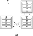
- FIG. 9 depicts an example system 900 according to example embodiments of the present disclosure.
- the system 900 can include the computing system 104, the platforms 102A-G, which can be configured to communicate via the network 910, such as, a very high frequency (VHF) network, high frequency (HF) network, SATCOM network, WiFi network, and/or any other suitable communication network.
- the platforms 102A-G can be located at a remote location that is separated and remote from the computing system 104.
- the computing system 104 can be associated with a ground-based operation and/or command center and the platforms 102A-G can be deployed (e.g., airborne, travelling in water, underwater).
- the system 900 can include the observation device(s) 110.
- the computing system 104 can include one or more computing device(s) 106.
- the computing device(s) 106 can include one or more processor(s) 106A and one or more memory device(s) 106B.
- the one or more processor(s) 106A can include any suitable processing device, such as a microprocessor, microcontroller, integrated circuit, logic device, and/or other suitable processing device.
- the one or more memory device(s) 106B can include one or more computer-readable media, including, but not limited to, non-transitory computer-readable media, RAM, ROM, hard drives, flash drives, and/or other memory devices.
- the one or more memory device(s) 106B can store information accessible by the one or more processor(s) 106A, including computer-readable instructions 106C that can be executed by the one or more processor(s) 106A.
- the instructions 106C can be any set of instructions that when executed by the one or more processor(s) 106A, cause the one or more processor(s) 106A to perform operations.
- the instructions 106C can be executed by the one or more processor(s) 106A to cause the one or more processor(s) 106A to perform operations, such as any of the operations and functions for which the computing system 104 and/or the computing device(s) 106 are configured, the operations for providing a synthetic track to one or more observation device(s) (e.g., method 700), as described herein, and/or any other operations or functions of the one or more computing device(s) 106.
- the instructions 106C can be software written in any suitable programming language or can be implemented in hardware. Additionally, and/or alternatively, the instructions 106C can be executed in logically and/or virtually separate threads on processor(s) 106A.
- the memory device(s) 106B can further store data 106D that can be accessed by the processors 106A.
- the data 106D can include data and/or information associated with the location range 116, the time range 118, the emission locations 120A-G, the emission times 122A-G, the sets of data 128A-G, the travel paths of the platforms 102A-G, data and/or information associated with the platforms 102A-G, data and/or information associated with the observation device(s) 110, and/or any other data and/or information described herein.
- the computing device(s) 106 can also include a communication interface 106E used to communicate, for example, with the other components of system 900 (e.g., via network 910).
- the communication interface 106E can include any suitable components for interfacing with one or more network(s), including for example, transmitters, receivers, ports, controllers, antennas, and/or other suitable components.
- the platforms 102A-G can include one or more computing device(s) 902.
- the computing device(s) 902 can include one or more processor(s) 902A and one or more memory device(s) 902B.
- the one or more processor(s) 902A can include any suitable processing device, such as a microprocessor, microcontroller, integrated circuit, logic device, and/or other suitable processing device.
- the one or more memory device(s) 902B can include one or more computer-readable media, including, but not limited to, non-transitory computer-readable media, RAM, ROM, hard drives, flash drives, and/or other memory devices.
- the one or more memory device(s) 902B can store information accessible by the one or more processor(s) 902A, including computer-readable instructions 902C that can be executed by the one or more processor(s) 902A.
- the instructions 902C can be any set of instructions that when executed by the one or more processor(s) 902A, cause the one or more processor(s) 902A to perform operations.
- the instructions 902C can be executed by the one or more processor(s) 902A to cause the one or more processor(s) 902A to perform operations, such as any of the operations and functions for which the platforms 102A-G and/or the computing device(s) 902 are configured, the operations for providing a synthetic track to one or more observation device(s) (e.g., method 700), as described herein, and/or any other operations or functions of the platforms 102A-G.
- the instructions 902C can be software written in any suitable programming language or can be implemented in hardware. Additionally, and/or alternatively, the instructions 902C can be executed in logically and/or virtually separate threads on processor(s) 902A.
- the memory device(s) 902B can further store data 902D that can be accessed by the processors 902A.
- the data 902D can include data and/or information associated with the location range 116, the time range 118, the emission locations 120A-G, the emission times 122A-G, the sets of data 128A-G, the travel paths of the platforms 102A-G, data and/or information associated with the computing system 104, data and/or information associated with the platforms 102A-G, data and/or information associated with the observation device(s) 110, and/or any other data and/or information described herein.
- the computing device(s) 902 can also include a communication interface 902E used to communicate, for example, with the other components of system 900.
- the communication interface 902E can be used to communicate with the computing device(s) 106 via the network(s) 910. Additionally, and/or alternatively, the communication interface 902E can be configured to generate the emissions 126A-G.
- the communication interface 902E can include any suitable components for interfacing with the one or more network(s) 910 and/or any suitable components for generating the emissions 126A-G, including for example, transmitters, receivers, ports, controllers, antennas, and/or other suitable components.
- the observation device(s) 110 can include one or more computing device(s) 114.
- the computing device(s) 114 can include one or more processor(s) 114A and one or more memory device(s) 114B.
- the one or more processor(s) 114A can include any suitable processing device, such as a microprocessor, microcontroller, integrated circuit, logic device, and/or other suitable processing device.
- the one or more memory device(s) 114B can include one or more computer-readable media, including, but not limited to, non-transitory computer-readable media, RAM, ROM, hard drives, flash drives, and/or other memory devices.
- the one or more memory device(s) 114B can store information accessible by the one or more processor(s) 114A, including computer-readable instructions 114C that can be executed by the one or more processor(s) 114A.
- the instructions 114C can be any set of instructions that when executed by the one or more processor(s) 114A, cause the one or more processor(s) 114A to perform operations.
- the instructions 114C can be executed by the one or more processor(s) 114A to cause the one or more processor(s) 114A to perform operations, such as any of the operations and functions for which the observation device(s) 110 and/or the computing device(s) 114 are configured, the operations for identifying a synthetic track (e.g., method 800), as described herein, and/or any other operations or functions of the one or more observation device(s) 110.
- the instructions 114C can be software written in any suitable programming language or can be implemented in hardware. Additionally, and/or alternatively, the instructions 114C can be executed in logically and/or virtually separate threads on processor(s) 114A.
- the memory device(s) 114B can further store data 114D that can be accessed by the processors 114A.
- the data 114D can include data and/or information associated with the emissions 126A-G, data associated with the synthetic track 108 (e.g., irregularities, deviations), data and/or information associated with the platforms 102A-G, and/or any other data and/or information described herein.
- the computing device(s) 114 can also include a communication interface 114E.
- the communication interface 114E can be used to send signals 502A-C to the platforms 102A-G and/or receive, detect, monitor, observe, etc. emissions 126A-G.
- the communication interface 114E can include any suitable components for sending and receiving signals and/or emissions, including for example, transmitters, receivers, ports, controllers, antennas, and/or other suitable components.
Landscapes
- Engineering & Computer Science (AREA)
- Radar, Positioning & Navigation (AREA)
- Remote Sensing (AREA)
- Computer Networks & Wireless Communication (AREA)
- Physics & Mathematics (AREA)
- General Physics & Mathematics (AREA)
- Signal Processing (AREA)
- Electromagnetism (AREA)
- Microelectronics & Electronic Packaging (AREA)
- Computer Security & Cryptography (AREA)
- Aviation & Aerospace Engineering (AREA)
- Radar Systems Or Details Thereof (AREA)
- Traffic Control Systems (AREA)
Abstract
Description
- The present subject matter relates generally to providing location deception and more particularly to providing angular location deception using a plurality of platforms.
- Deception techniques can be used to mislead an adverse observer as to the location of a vehicle. For instance, an aircraft can create deception as to the distance and/or speed of the aircraft, thereby misleading the observer as to the actual location of the aircraft. However, the observers can overcome such deception by deploying multiple observation angles to determine the actual aircraft position based on line-of-sight of each observation angle to the aircraft.
- Aspects and advantages of embodiments of the present disclosure will be set forth in part in the following description, or may be learned from the description, or may be learned through practice of the examples disclosed herein.
- One example aspect of the present disclosure is directed to a computer-implemented method of identifying a synthetic track. The method can include receiving, by one or more computing devices, a plurality of emissions from one or more platforms. The emissions can be generated in an emission sequence and can be generated to create a track indicative of an object travel path. The method can further include determining, by the one or more computing devices, whether an irregularity associated with the track exists based at least in part on one or more of the emissions. The method can include rejecting, by the one or more computing devices, the track as an actual object travel path when it is determined that the irregularity associated with the track exists.
- Another example aspect of the present disclosure is directed to a computing system for identifying a synthetic track. The system can include one or more processors and one or more memory devices. The one or more memory devices can store instructions that when executed by the one or more processors cause the one or more processors to receive a plurality of emissions from a plurality of platforms, wherein the plurality of emissions are generated to create a track. The track aims to create an object travel path, and wherein a first angle associated with the track is different than a plurality of second angles associated with the travel paths of the plurality of aerial platforms. The processors can be further caused to determine whether an irregularity associated with the track exists based at least in part on one or more of the emissions. The processors can be caused to reject the track as an actual object travel path when it is determined that the irregularity associated with the track exists.
- Yet another example aspect of the present disclosure is directed to an observational device for identifying a synthetic track. The observation device can include one or more processors and one or more memory devices. The one or more memory devices can store instructions that when executed by the one or more processors cause the one or more processors to receive a plurality of emissions from a plurality of platforms. The plurality of emissions can be generated to create a track. The track can aim to create an object travel path that is observable by the observation device. The track can include one or more bearing angles that create angular deception intending to mislead as to travel paths of the one or more platforms. The processors can be further caused to determine whether an irregularity associated with the track exists based at least in part on one or more of the emissions. The processors can be caused to reject the track as an actual object travel path when it is determined that the irregularity associated with the track exists.
- Other example aspects of the present disclosure are directed to systems, methods, aircrafts, avionics systems, devices and non-transitory computer-readable media for providing a synthetic track to one or more observation devices as well as observation devices for identifying synthetic tracks.
- Variations and modifications can be made to these example aspects of the present disclosure.
- These and other features, aspects and advantages of various examples will become better understood with reference to the following description and appended claims. The accompanying drawings, which are incorporated in and constitute a part of this specification, illustrate aspects of the present disclosure and, together with the description, serve to explain the related principles.
- Detailed discussion of embodiments directed to one of ordinary skill in the art are set forth in the specification, which makes reference to the appended figures, in which:
-
FIG. 1 depicts an example system according to example embodiments of the present disclosure; -
FIG. 2 depicts an example orientation of a plurality of platforms according to example embodiments of the present disclosure; -
FIG. 3 depicts an example orientation of a plurality of platforms according to example embodiments of the present disclosure; -
FIG. 4 depicts an example orientation of a plurality of platforms according to example embodiments of the present disclosure; -
FIG. 5 depicts an example orientation of a plurality of platforms according to example embodiments of the present disclosure; -
FIG. 6 depicts an example orientation of a plurality of platforms according to example embodiments of the present disclosure; -
FIG. 7 depicts a flow diagram of an example method for providing a synthetic track to one or more observation devices according to example embodiments of the present disclosure; -
FIG. 8 depicts a flow diagram of an example method for identifying a synthetic track according to example embodiments of the present disclosure; and -
FIG. 9 depicts an example system according to example embodiments of the present disclosure. - Reference now will be made in detail to embodiments of the present disclosure, one or more example(s) of which are illustrated in the drawings. Each example is provided by way of explanation of the present disclosure, not limitation of the present disclosure. In fact, it will be apparent to those skilled in the art that various modifications and variations can be made in the present disclosure without departing from the scope or spirit of the present disclosure. For instance, features illustrated or described as part of one embodiment or implementation can be used with another embodiment or implementation to yield a still further embodiment. Thus, it is intended that the present disclosure covers such modifications and variations as come within the scope of the appended claims and their equivalents.
- Example aspects of the present disclosure are directed to systems and methods for providing a synthetic track to one or more observation devices. For instance, a computing system (e.g., associated with an operations/command center) can coordinate a plurality of platforms to generate a sequence of either responsive or non-responsive emissions to project a synthetic track. The platforms can include, for instance, multi-function emitter platforms, UAVs, aerial platforms, water platforms, platforms capable of traveling/operating underwater, platforms capable of operating in outer space, etc. The synthetic track can be a false object travel path and/or implied vehicle path (or paths) that can be observable by the one or more observation device(s) (e.g., radar devices of an adverse entity). Moreover, the orientation of the synthetic track can be different from the actual travel paths of the platforms. The synthetic, of false, track intentionally may be designed to not correspond with the physical motion of any platforms. The synthetic track can create angular deception to mislead the observation devices as to the actual travel paths and/or locations of the platforms. To do so, for example, the synthetic track can be associated with a bearing angle that is different than the travel paths of the platforms.
- The computing system can determine a location and/or time range in which to create such a synthetic track. Based, at least in part, on the prescribed location and/or time range the computing system can determine a sequence of location and time pairings for each platform of the plurality of platforms (e.g., a swarm of aerial platforms) to generate an emission. The computing system can send data indicative of the emission times and/or locations to the platforms such that the platforms can generate the emissions in a sequence to create the synthetic track within the location range and/or the time range. In this way, the sequence of emissions (or delayed versions of existing radar or communications signals) from the various platforms can create one of more false targets which appear to move in space. Any single emission will appear along the radial between the platform and any particular observer, but subsequent emissions move to a new radial creating apparent bearing change and angular deception.
- More particularly, the computing system can identify a travel path for each platform of the plurality of platforms. This can be done while one or more of the platforms are deployed (e.g., a swarm of airborne platforms) and/or before one or more of the platforms are deployed. In some implementations, one or more of the platform(s) can be associated with one or more static travel path(s), such that the respective platform remains generally at a single location. In such a case, the stationary platforms can exist along a line and sequential emissions can create the appearance of motion, as further described herein. In some implementations, one or more of the platform(s) can be associated with one or more non-static travel path(s), such that the platform(s) can travel in space, for example, in a parallel and/or arbitrary manner relative to one another.
- The computing system can determine a location range and/or a time range for a synthetic track to be created by the plurality of platforms. In some implementations, this determination can be based, at least in part, on the travel path for each platform. For example, a very large number of platforms can be deployed within minimal constraints on four dimensional locations. The computing system can dynamically select/prescribe the actions of the platforms (e.g., generating emissions to create a synthetic track) based, at least in part, on the travel paths of the platforms. Additionally, and/or alternatively, the location range and/or the time range can be based, at least in part, on the position, type, orientation, etc. of the one or more observation device(s).
- The computing system can determine an emission location and/or an emission time for each of the plurality of platforms based, at least in part, on the location range and/or the time range. The emission location can be indicative of a location at which the respective platform is to generate an emission. The emission time can be indicative of a time at which the respective platform is to generate the emission. The emission locations and/or emission times can be selected to create the appearance of motion along a synthetic track. The apparent speed (of the "false" target moving along the synthetic track) can be selected by the ratio of the physical spacing between platforms and/or emissions divided by the time between emissions.
- The computing system can send a set of data to each of the plurality of platforms. Each respective set of data can indicate the emission location and/or the emission time at which the respective platform is to generate the emission to create the synthetic track. In this way, the computing device(s) can coordinate the platforms such that they are to generate the emissions in a sequence based, at least in part, on the emission locations and/or the emission times to create the synthetic track within the desired location range and/or the time range. The platforms can receive the sets of data and generate the emissions, at the emission times and/or locations, to create the synthetic track. To the observation device(s), the observed synthetic track(s) can match and would be consistent with TDOA (time difference of arrival) techniques.
- The emissions can be non-responsive or responsive. For example, the platforms can generate the emissions not in response to signals from the observation devices. In some implementations, as further described herein, the platforms can generate the emissions in response to receiving signals from the observation devices. In such a case, the platforms can utilize unique Doppler correction (and/or Doppler dilution), if desired, in the event that the platform paths are not at a desired location, have non-parallel paths, are not of the same speed, etc.
- Additionally, and/or alternatively, the plurality of platforms can represent a swarm of platforms that can be used in any of the systems and/or methods described herein. For instance, the platforms can be deployed within minimal constraints on four dimensional locations. The computing system can dynamically select emission locations and/or times based, at least in part, on the travel paths of the platforms. In the case of non-responsive emissions (as further described herein), this can allow for more frequent updates consistent with one or more desired synthetic tracks. For the responsive emissions (as further described herein), particularly within systems which utilize "random" search actions, this added flexibility can greatly reduce the chances of not having a platform in an appropriate four-dimensional position consistent with the desired synthetic track. In addition to potentially maintaining multiple synthetic tracks, the swarm could also provide synthetic tracks using the techniques described herein. Further, the swarm approach can make it feasible to support consistent responsive synthetic tracks for multiple observation device(s) operating diversely, as well as refine estimation of parameters associated with observation device(s) (e.g., beam-width) by the platforms.
- Additional aspects of the present disclosure are directed to systems and methods for identifying a synthetic track. For instance, the observation device(s) can examine the emissions from the platforms to determine whether or not to accept the synthetic track as a possible motion path of an object. As further described herein, the observation device(s) can determine whether an irregularity associated with the synthetic track exists such that it would be unrealistic for the synthetic track to be associated with an actual object in motion. The observation device(s) can then accept and/or reject the synthetic track based, at least in part, on the existence of an irregularity.
- The systems and methods according to example aspects of the present disclosure provide effective location detection techniques. More particularly, by utilizing a plurality of platforms, the systems and methods can provide synthetic tracks that include one or more bearing angles that create angular deception intending to mislead an observation device as to the actual locations and/or travel paths of the platforms. This can lead to confidence weakening of adverse observation devices. Moreover, the system and methods enable the platforms to create such deception even if the platform is positioned away from a desired location. In this way, the systems and methods according to example aspects of the present disclosure have a technical effect of creating false synthetic tracks with significant cross range motion which can introduce time-criticality to further support early warning and/or asset/area defense.
- Moreover, the systems and methods according to example aspects of the present disclosure provide effective techniques for identifying potential location deception. More particularly, by examining the emissions of the plurality of platforms, an observation device can identify whether the platforms aim to create a false object travel path to deceive the observation device. This can allow an observation device to disregard false tracks and to allocate its resources to following physical targets-of interest. In this way, the systems and methods according to example aspects of the present disclosure have a technical effect of identifying false synthetic tracks to preserve computational resources for the monitor of a real physical target, while increasing the effectiveness of actual hostile platform detection.
-
FIG. 1 depicts anexample system 100 according to example embodiments of the present disclosure. As shown thesystem 100 can include a plurality ofplatforms 102A-G and acomputing system 104. As further described herein, theplatforms 102A-G and thecomputing system 104 can be configured to communicate with one another (e.g., to send and/or receive data). - The
platforms 102A-G can include a multi-function emitter platform, a remotely operated platform (ROAP), an unmanned vehicle (UAV), a helicopter, a drone, other aircraft, a watercraft, a vehicle capable of operating underwater, underwater platform, and/or any other device capable of sufficient maneuverability for the operations described herein. Eachplatform 102A-G of the plurality ofplatforms 102A-G can be physically separated from each of theother platforms 102A-G of the plurality ofplatforms 102A-G. For instance, in some implementations, no wires and/or other components need be configured to physically couple the plurality ofplatforms 102A-G to one another. Each of theplatforms 102A-G can include one or more computing device(s). The computing device(s) can include various components for performing various operations and functions. For example, the computing device(s) can include one or more processor(s) and one or more memory device(s). The one or more memory device(s) can store instructions that when executed by the one or more processor(s) cause the one or more processor(s) to perform the operations and functions for providing a synthetic track, as described herein. - The
computing system 104 can be associated with an entity that maintains, controls, monitors, and/or is otherwise associated with the operation of theplatforms 102A-G. For instance, thecomputing system 104 can be associated with an operations and/or command center for theplatforms 102A-G (e.g., a ground-based center, airborne control node, other control node). Thecomputing system 104 can include one or more computing device(s) 106. The computing device(s) 106 can include various components for performing various operations and functions. For example, and as further described herein, the computing device(s) 106 can include one or more processor(s) and one or more memory device(s). The one or more memory device(s) can store instructions that when executed by the one or more processor(s) cause the one or more processor(s) to perform the operations and functions, as described herein. - The computing device(s) 106 can be configured to coordinate the creation of a
synthetic track 108, by at least some of theplatforms 102A-G, that can be observed by one or more observation device(s) 110. Thesynthetic track 108 can be a false object travel path and/or a realistic implied vehicle path (or paths) that can be observable by the one or more observation device(s) 110. Thesynthetic track 108 can create an angular deception to mislead the observation device(s) 110 as to the actual location of one or more of theplatforms 102A-G. For instance, afirst angle 112 associated with thesynthetic track 108 can be different than a plurality of second angles associated with the travel paths of the plurality ofplatforms 102A-G, as further described herein. - The observation device(s) 110 can include a radar device, tracking device, monitoring device, anti-aircraft device, water associated device, etc. associated with an entity that the operators/controllers of the
platforms 102A-G desire to mislead as to the location and/or travel paths of theplatforms 102A-G. For example, the observation device(s) 110 can be associated with an adverse and/or hostile entity/party. In another example, the observation device(s) 110 can be associated with an entity/party (e.g., non-hostile) that does not have permission, clearance, a need-to-know, etc. to know and/or identify the location and/or travel paths of theplatforms 102A-G. The observation device(s) 110 can include one or more computing device(s) 114. The computing device(s) 114 can include various components for performing various operations and functions, such as recognizing a synthetic track as further described herein. - The computing device(s) 106 can be configured to identify a travel path for each
platform 102A-G of the plurality ofplatforms 102A-G. A travel path can be a flight path of an aerial platform, a travel path of a watercraft platform, a travel path of an underwater platform, a travel path of another platform type, etc. In some implementations, one or more of theplatforms 102A-G of the plurality ofplatforms 102A-G can be associated with a travel path such that therespective platform 102A-G remains generally at a single location. For instance,FIG. 2 depicts anexample orientation 200 of the plurality ofplatforms 102A-G. As shown inFIG. 2 , thetravel paths 202A-G of each of theplatforms 102A-G can be static, such that therespective platform 102A-G remains generally at a single location in space. - In some implementations, one or more of the
platforms 102A-G can be associated with a non-static flight plan, such that therespective platform 102A-G travels from more than one location. For instance,FIG. 3 depicts anexample orientation 300 of the plurality ofplatforms 102A-G. As shown inFIG. 3 , one ormore platform 102A-G of the plurality ofplatforms 102A-G can be associated with atravel path 302A-G that includes a segment that is in a generally parallel direction relative to one or more travel paths of one or moreother platforms 102A-G of the plurality ofplatforms 102A-G. - In some implementations, one or more of the platforms 102 can be associated with an arbitrary travel path, such that the
respective platform 102A-G travels from more than one location in an arbitrary direction relative to the other platforms. For instance,FIG. 4 depicts anexample orientation 400 of the plurality ofplatforms 102A-G. As shown inFIG. 4 , one ormore platform 102A-G of the plurality ofplatforms 102A-G can be associated with atravel path 402A-G that includes a segment that is in a generally arbitrary direction relative to one or more travel paths of one or moreother platforms 102A-G of the plurality ofplatforms 102A-G. - Returning to
FIG. 1 , the computing device(s) 106 can be configured to determine alocation range 116 and/or a time range 118 for thesynthetic track 108 to be created by the plurality ofplatforms 102A-G based, at least in part, on the travel path (e.g., 202A-G, 302A-G, 402A-G) for each platform. For instance, the computing device(s) 106 can be configured to determine that it would like to create (e.g. create the appearance of) thesynthetic track 108 within thelocation range 116. Additionally, and/or alternatively, the computing device(s) 106 can be configured to determine that it would like to create (e.g. create the appearance of) thesynthetic track 108 within the time range 118. Such determinations can be based, at least in part, for example, on the presence and/or location of the observation device(s) 110, a particular objective, etc. The computing device(s) 106 can examine the respective travel paths (e.g., 402A-G) of each of theplatforms 102A-G and determine when and where each of theplatforms 102A-G will be and at which point(s) in the travel paths (e.g., 402A-G) theplatforms 102A-G should generate an emission such that thesynthetic track 108 appears within thelocation range 116 and/or the time range 118. In some implementations, the computing device(s) 106 can determine thelocation range 116 and/or the time range 118 for thesynthetic track 108 and send a command signal and/or travel path to theplatforms 102A-G such that theplatforms 102A-G are properly positioned to create (e.g. create the appearance of) thesynthetic track 108 within thelocation range 116 and/or the time range 118. - The computing device(s) 106 can determine an
emission location 120A-G and/or anemission time 122A-G for eachplatform 102A-G of the plurality ofplatforms 102A-G based, at least in part, on thelocation range 116 and/or the time range 118. The emission location can be indicative of a location (e.g., p1 ... p7 ... pn) at which therespective platform 102A-G is to generate anemission 126A-G. Theemission time 122A-G can be indicative of a time (e.g., t1 ... t7 ... tn) at which therespective platform 102A-G is to generate anemission 126A-G. By way of example, in order to create thesynthetic track 108 within thelocation range 116 and/or the time range 118 the computing device(s) 106 can determine that afirst platform 102A should generate anemission 126A at theemission location 120A and theemission time 122A. Theemission location 120A and theemission time 122A can be identified such that theemission 126A is generated to create at least a portion of thesynthetic track 108 within the location range 116A and thetime range 122A. This process can be repeated for each of theplatforms 102A-G. Theemission times 122A-G, for each of theplatforms 102A-G, can be separated by fixed time intervals. This can allow thesynthetic track 108 to appear more realistic (e.g., similar to a real vehicle travel path) to the observation device(s) 110. - The computing device(s) 106 can be configured to coordinate the creation of the
synthetic track 108 by, for instance, sending a set ofdata 128A-G to each of the plurality ofplatforms 102A-G. Each respective set ofdata 128A-G can indicate theemission location 120A-G and/or theemission time 122A-G at which therespective platform 102A-G is to generate anemission 126A-G to create (at least a portion of) thesynthetic track 108. By way of example, the set ofdata 128A can indicate theemission location 120A (e.g., p1) and/or theemission time 122A (e.g., t1) at which therespective platform 120A is to generate theemission 126A, to create (at least a portion of) thesynthetic track 108. - In some implementations, the set of
data 128A can include only theemission time 122A-G. For instance, eachemission time 122A-G can be associated with a location in the travel path (e.g., 402A) of the respective platform (e.g., 102A) such that the emissions are generated within thelocation range 116. By way of example, in the event that theplatform 102A is configured to travel (or is travelling) according to a set travel plan and/or travel path (e.g., 402A), theplatform 102A may only need to know when to generate theemission 126A as the location of theplatform 102A can be predetermined for each time along thetravel path 402A. - Each
platform 102A-G of the plurality ofplatforms 102A-G can be configured to receive a set ofdata 128A-G indicating anemission location 120A-G and/or anemission time 122A-G at which theplatform 102A-G is to generate anemission 126A-G. In some implementations, theplatforms 102A-G can receive the set ofdata 128A-G when one or more (or each)platform 102A-G of the plurality of platforms102A-G is deployed (e.g., travelling, airborne, underwater). In some implementations, the set ofdata 128A-G can be received by theplatforms 102A-G before one or more (or each) of theplatforms 102A-G are deployed. In this way, the computing device(s) 106 can pre-program theplatforms 102A-G to create thesynthetic track 108 within the location and/or time ranges 116, 118. - Each
platforms 102A-G can be configured to generate anemission 126A-G at theemission location 120A-G and/oremission time 122A-G (e.g., indicated in the set ofdata 128A-G) such that at least a portion of thesynthetic track 108 is created by theemissions 126A-G of theplatform 102A-G within thelocation range 116 and/or time range 118. Theemissions 126A-G can include a radio-frequency (RF) emission, a light emission, a sonar emission, and/or other types of emissions that can be observed and/or detected by the observation device(s) 110. Eachemission 126A-G can be similar to the other emissions such that they appear, to the observation device(s) 110, to be generated by the same source. In some implementations, theemissions 126A-G can be separated by fixed time intervals. In this way, it can appear, to theobservation devices 110, as if a platform is moving in the direction of thesynthetic track 108, when in fact, no such platform exits. - Additionally, and/or alternatively, the
emissions 126A-G can vary in reflectivity and/or emissivity from one another. By way of example, the set ofdata 128A-G can be indicative of a reflectivity and/or emissivity associated at which arespective emission 126A-G is to be generated by theplatform 102A-G. Eachplatform 102A-G can generate its respective emission based, at least in part, on the reflectivity and/or emissivity indicated in the set ofdata 128A-G. The reflectivity and/or emissivity associated with emission of a platform can be different than one or more reflectivity and/or emissivity associated with the emissions of other platforms. In this way, a location/time sequence of varying reflectivity and/or emissivity can be employed to provide further deception of the observation device(s) 110. - The plurality of
platforms 102A-G can generate theemissions 126A-G in a sequence based, at least in part, on theemission locations 120A-G and/oremission times 122A-G to create thesynthetic track 108. By way of example, afirst platform 102A can be configured to generate afirst emission 126A at afirst emission location 120A (e.g., p1) and/or at afirst emission time 122B (e.g., t1). Thefirst emission 126A can be the first emission in the sequence. Asecond platform 102B can be configured to generate asecond emission 126B at asecond emission location 120B (e.g., p2) and/or at asecond emission time 122A (e.g., t2). Thesecond emission 126B can occur after thefirst emission 126A. Athird platform 102C can be configured to generate athird emission 126C at athird emission location 120C (e.g., p3) and/or at athird emission time 122C (e.g., t3). Thethird emission 126C can occur after thesecond emission 126B. Afourth platform 102D can be configured to generate afourth emission 126D at afourth emission location 120D (e.g., p4) and/or at afourth emission time 122D (e.g., t4). Thefourth emission 126D can occur after thethird emission 126C. This process can continue in a similar manner with afifth platform 102E andsixth platform 102F. Aseventh platform 102G can be configured to generate aseventh emission 126G at aseventh emission location 120G (e.g., p7) and/or at aseventh emission time 122G (e.g., t7). Theseventh emission 126G can represent the last emission in the sequence although the present disclosure can include more or less numbers of emissions and/or platforms without deviating from the scope of the present disclosure. In this way, the first throughseventh emissions 126A-G can be generated in the above-described sequence such that it appears that an platform is traveling along thesynthetic track 108 and making periodic emissions. As shown, for example inFIG. 4 , thesynthetic track 108 created by theemissions 126A-G can be associated with afirst angle 112 that is different than a plurality ofsecond angles 404A-G associated with one ormore travel paths 402A-B of the plurality ofplatforms 102A-G. In this way, theplatforms 102A-G can be configured to create angular deception to mislead the observation device(s) 110 to determine that a false platform is traveling in a direction and/or angle that is different than theplatforms 102A-G. - For example, to multiple observation device(s) 110, the observed
synthetic track 108 could match and be consistent with TDOA (time difference of arrival) data, if available. Depending on the types of sensors and systems merging data, some matches and/or mismatches can be created in an effort to exploit specific logic. For example, observation device(s) 110 with matching synthetic tracks and TDOA data would find that frequency difference of arrival (FDOA) does not match the synthetic track 108 (unless emission frequencies were tailored as a function of angle, and would only work with good sidelobes or noise cover). This can arise because spatially separated FDOA receivers can observe differing Doppler shifts depending on the relative orientation to the apparentsynthetic track 108. Moreover, thesynthetic track 108 can create a mismatch from FDOA data because the synthetic track Doppler does not have the correct variation as a function angle from thesynthetic track 108. The FDOA mismatch may be a positive or negative feature, depending on the victim systems and desired effect. In some implementations, creating conflicts in observation device(s) 110 may be sufficient to deceive the observation device(s) 110 or proper correlation among multiple observers. For example, if theplatforms 120A-G are associated with arbitrary travel paths, they can still maintain a synthetic track aligned with TDOA and introduce substantial randomness into FDOA; if the FDOA confidence breaks down, there may be restored (false) confidence in the false arbitrarily synthetic (and TDOA) track. - Similarly, a burst of
emissions 126A-G from eachplatform 102A-G can appear to create a series of false targets along the instantaneous radial from theplatforms 102A-G to observation device(s) 110. The apparent formation orientation can differ between observation device(s) 110 and the formation orientation can rotate over time. Accordingly, the observation device(s) 110 can be misled as to the actual locations and/or travel paths of theplatforms 102A-G. - In some implementations, the
emissions 126A-G can be generated not in response to one or more signal(s) from one or more observation device(s) 110. For example,FIGS. 2-5 depict example implementations in which theemissions 126A-G are not generated in response to the plurality ofplatforms 102A-G receiving one or more signal(s) from one or more observation device(s) 110. - In some implementations, one or more of the
emissions 126A-G can be generated by one or more of the platform(s) 126A-G in response to one or more of theplatforms 102A-G receiving one or more signal(s) from one or more observation device(s) 110. For instance,FIG. 5 depicts anexample orientation 500 of the plurality ofplatforms 102A-C. The computing device(s) 114 (of the observation device(s) 110) can send one or more signals(s) 502A-C to theplatforms 102A-G. The platform(s) 102A-C can receive one or more signal(s) 502A-C from the observation device(s) 110. The signal(s) 502A-C can be encoded to induce a response from the platform(s) 102A-C to facilitate the monitoring of such platforms. - As shown in
FIG. 5 , one or more of the platform(s) 102A-C can be located at a position other than the emission location determined by the computing device(s) 106. For instance, thefirst platform 102A can be located at aposition 502A (e.g., p1') when it receives afirst signal 502A (e.g., at a time t1'). If thefirst platform 102A responded immediately following receipt of thesignal 502A (e.g., with thefirst platform 102A at a position p1', at a time t1') then the sequence of emissions may create a synthetic track that does not appear like that of real platform. This can lead to a risk of the observation device(s) 110 rejecting the synthetic track. - To address this, one or more of the
platforms 102A-C can be configured to determine a time delay and adjust its emission time such that the emissions appear to be generated within the location range 116 (at an appropriate time), in accordance with the planned sequence. For instance, thefirst platform 102A can be configured to receive thefirst signal 502A from the one or more observation device(s) 110. Thefirst platform 102A can be configured to determine atime delay 506A (e.g., d1) based, at least in part, on thesignal 502A received from the one or more observation device(s) 110. For instance, thetime delay 506A (e.g., d1) can include the time necessary for thefirst emission 126A to appear as if it was generated from a position (e.g., p1) within thelocation range 116. Thefirst platform 102A can adjust its emission time based, at least in part, on thetime delay 506A (e.g., d1), such that thefirst emission 126A can be generated at the adjustedemission time 508A to create at least the portion of a synthetic track 108 (to appear) within thelocation range 116. In some implementations, thefirst platform 102A and/or the computing device(s) 106 can communicate with thesecond platform 102B,third platform 102C, etc. to inform the other platforms of the delay in one or more of the emissions, so that the other emission locations and/or times can be generated to create a synthetic track that will not be rejected by the observation device(s) 110. - In some implementations, the
time delay 506A can be indicative of a range at which theemission 126A can be generated. For instance,FIG. 6 depicts anexample orientation 600 of the plurality ofplatforms 102A-C. Thefirst platform 102A can be configured to receive thefirst signal 502A from the one or more observation device(s) 110. Thefirst platform 102A can estimate anobservational error 602 associated with the one or more observation device(s) 110 based, at least in part, on thesignal 502A received from the one or more observation device(s) 110. For example, thefirst platform 102A can determine theobservational error 602 based, at least in part, on the transmitting power, the wavelength, the beam width, other characteristics, etc. associated with thesignal 502A. - The
first platform 102A can be configured to determine thetime delay 506A based, at least in part, on theobservational error 602. Thetime delay 506A can be indicative of arange 604 at which theemission 126A can be generated. Therange 604 can include an emission location range (e.g., p1-Δp ... p1+Δp) and/or an emission time range (e.g., t1-Δt... t1+Δt) in which thefirst platform 102A can generate theemission 126A such that, at least a portion of, thesynthetic track 108 will not be rejected by the observation device(s) 110. For instance, because there is observational error (e.g., 602) associated with observation device(s) 110 it is possible that thesynthetic track 108 does not have to be perfectly straight and/or includeemissions 126A-G within perfectly segmented intervals. Rather, thefirst platform 102A can have a degree of freedom as to when and/or where it creates thefirst emission 126A in response to thefirst signal 502A, such that thesynthetic track 108 will still be accepted by the observation device(s) 110. Therange 604 can be indicative of such degree of freedom. - For example, the observation device(s) 110 can have a fairly wide angle association gate appropriate for the specific measurement errors, thus "imperfect angle" response emissions (e.g., creating the synthetic track) could be accepted and not recognized as unusual. If a time gap (e.g., between response emissions) is large compared to drop track criteria, additional response emissions could be included with proper timing but have an imperfect angle. Unless the individual travel paths of the
platforms 102A-G are designed to mimic the proper cross range rate (of the synthetic track 108), there can be some error in the apparent cross range position. However, if these imperfect angles fell within the association gates of the observation device(s) 110 they could be accepted by the observation device(s) 110. - Additionally, and/or alternatively, over a certain time window, additional response emissions can be generated and accepted by the observation device(s) 110, unless specific novel logic (described below with respect to
FIG. 8 ) was implemented. This time window can be designed to fall within the anticipated angle gate of the observation device(s) 110 (e.g., this can be approximately or exactly known and/or can be estimated given the beamwidth and SNR) with down-range time adjustments accounting for the differing trajectory between anyindividual platform 102A-G and thesynthetic track 108. The time window could be viewed, for example, as a method to counter imperfect angular positioning of thefirst platform 102A. In some implementations, theplatforms 102A-G can know its own effective radiated power, and thus, SNR estimation associated with observation device(s) 110 can be accomplished utilizing a priori/told-in positional information or localization techniques, such as TDOA measurements, from theplatform 102A-G themselves. - The number of components (e.g.,
platforms 102A-G,emissions 126A-G, synthetic track 108) shown inFIGS. 1-6 are not intended to be limiting. The systems and methods of the present disclosure can include more, less, and/or different components than shown inFIGS. 1-6 without deviating from the scope of the present disclosure. For example, more than one synthetic track can be created by one or more of theplatforms 102A-G. -
FIG. 7 depicts a flow diagram of anexample method 700 for providing a synthetic track to one or more observation devices according to example embodiments of the present disclosure.FIG. 7 can be implemented by one or more computing device(s) (e.g., the computing device(s) 106 depicted inFIGS. 1 and9 ) as well as a plurality of platforms (e.g., theplatforms 102A-G depicted inFIGS. 1-6 and9 ). One or more step(s) of themethod 700 can be performed while one or more (or each) of theplatforms 102A-G are deployed. In addition,FIG. 7 depicts steps performed in a particular order for purposes of illustration and discussion. Those of ordinary skill in the art, using the disclosures provided herein, will understand that the various steps of any of the methods disclosed herein can be modified, adapted, expanded, rearranged and/or omitted in various ways without deviating from the scope of the present disclosure. - At (702), the
method 700 can include determining a location range and/or a time range for a synthetic track. For instance, the computing device(s) 106 can determine alocation range 116 and/or a time range 118 for asynthetic track 108 to be created by the plurality ofplatforms 102A-G. In some implementations, this can be based, at least in part, on the position, type, orientation, etc. of the one or more observation device(s) 110. In some implementations, this determination can be based, at least in part, on the travel path (e.g., 202A-G, 302A-G, 402A-G) for eachplatform 102A-G. As further described herein, thesynthetic track 108 can be a false object travel path that is observable by the one or more observation device(s) 110. Thesynthetic track 108 can create angular deception to mislead the observation device(s) 110. For example, afirst angle 112 associated with thesynthetic track 108 can be different than a plurality of second angles (e.g., 404A-B) associated with one or more travel paths (e.g., 402A-G) of the plurality ofplatforms 102A-G. - At (704), the
method 700 can include identifying a travel path for each platform of a plurality of platforms. For instance, the computing device(s) 106 can identify a travel path (e.g., 202A-G, 302A-G, 402A-G) for eachplatform 102A-G of the plurality ofplatforms 102A-G. This can be done while one or more of the plurality ofplatforms 102A-G are deployed (e.g., a swarm of airborne platforms) and/or before one or more of the plurality ofplatforms 102A-G are deployed. In some implementations, one or more platform(s) 102A-G of the plurality ofplatforms 102A-G can be associated with one or more travel path(s) (e.g., 202A-G) that are static, such that the respective platform remains generally at a single location. In some implementations, one or more platform(s) 102A-G of the plurality ofplatforms 102A-G can be associated with one or more travel path(s) (e.g., 302A-G) that include a segment that is in a generally parallel direction relative to the travel paths (e.g., 302A-G) of one or more other platform(s) 102A-G of the plurality ofplatforms 102A-G. In some implementations, one or more platform(s) 102A-G of the plurality ofplatforms 102A-G can be associated with one or more travel path(s) (e.g., 402A-G) that include a segment that is in a generally arbitrary direction relative to one or more travel path(s) (e.g., 402A-G) of one or more other platform(s) 102A-G of the plurality ofplatforms 102A-G. - At (706), the
method 700 can include determining an emission location and/or emission time for each of the platforms of the plurality of platforms. For instance, the computing device(s) 106 can determine anemission location 120A-G and/or anemission time 122A-G for each of theplatforms 102A-G of the plurality ofplatforms 102A-G based, at least in part, on thelocation range 116 and/or the time range 118. Theemission location 120A-G can be indicative of a location at which therespective platform 102A-G is to generate anemission 126A-G. Theemission time 122A-G can be indicative of a time at which therespective platform 102A-G is to generate theemission 126A-G. In some implementations, theemission time 122A-G can be separated by fixed time intervals. - At (708), the
method 700 can include sending a set of data to each of the plurality of platforms. For instance, the computing device(s) 106 can send a set ofdata 128A-G to each of the plurality ofplatforms 102A-G. Each respective set ofdata 128A-G can indicate theemission location 120A-G and/or theemission time 122A-G at which therespective platform 102A-G is to generate theemission 126A-G to create thesynthetic track 108. In this way, the computing device(s) 106 can coordinate theplatforms 102A-G such that the plurality ofplatforms 102A-G are to generate theemissions 126A-G in a sequence based, at least in part, on theemission locations 120A-G and/or theemission times 122A-G to create thesynthetic track 108 within thelocation range 116 and/or the time range 118. The set ofdata 128A-G can also, and/or alternatively, include a travel path for theplatform 102A-G to follow. At (710), themethod 700 can include receiving the set of data. For instance, eachplatform 102A-G can receive the set ofdata 128A-G indicating theemission location 120A-G, theemission time 122A-G, and/or a travel path at which theplatform 102A-G is to generate theemission 126A-G. Theplatforms 102A-G can receive the sets ofdata 128A-G while airborne and/or while grounded (e.g., before deployment). As described herein, eachplatform 102A-G of the plurality ofplatforms 102A-G can be physically separated from each of theother platforms 102A-G of the plurality ofplatforms 102A-G. - At (712),
platforms 102A-G can travel according to a prescribed flight path. In some implementations, the flight path can allow theplatforms 102A-G to be properly positioned to make an emission 126A_G at theemission location 120A-G and/or theemission time 122A-G. - In some implementations, at (714), the
method 700 can include receiving a signal from the one or more observation devices. For instance, theplatforms 102A-G can receive one ormore signals 502A-C from the one or more observation device(s) 110. As described herein, the signal(s) 502A-C can be encoded to induce a response from the platform(s) 102A-C to facilitate the monitoring of such platforms by the observation device(s) 110. - In some implementations, at (716), the
method 700 can include determining an observational error associated with the one or more observation devices. For instance, theplatforms 102A-G can determine anobservational error 602 associated with the one or more observation device(s) 110 based, at least in part, on the one or more signal(s) 502A-C received from the one or more observation device(s) 110. By way of example, thefirst platform 102A can determine theobservational error 602 based, at least in part, on the transmitting power, the wavelength, the beam width, other characteristics, etc. associated with thesignal 502A. - In some implementations, at (718), the
method 700 can include determining a time delay based, at least in part, on the signal received from the one or more observation device(s). For instance, the platforms 102 can determine a time delay (e.g., 506A) based, at least in part, on the signal (e.g., 502A) received from the one or more observation device(s) 110. As described above, thetime delay 506A can include the time necessary for thefirst emission 126A to appear as if it was generated from a position (e.g., p1) within thelocation range 116. In some implementations, the time delay (e.g., 506A) can be based, at least in part, on theobservational error 602. For example, thetime delay 506A can be indicative of arange 604 at which theemission 126A can be generated. In this way, theplatforms 102A-G can leverage theobservational error 602 of the observation device(s) 110 such that the synthetic track is less likely to be rejected by the observation device(s) 110, as described above. - In some implementations, at (720), the
method 700 can include adjusting the emission time. For instance, theplatforms 102A-G can adjust theemission time 122A-G (and/or theemission location 120A-G) based, at least in part, on the time delay (e.g., 506A), such that theemission 126A-G is generated at the adjusted emission time (e.g., 508A) to create the appearance that at least a portion of thesynthetic track 108 is within thelocation range 116. One of more of the plurality of platform(s) 102A-G can delay the emission time (e.g., 508A) at which theplatform 102A-G is to generate theemission 126A-G, such that thesynthetic track 108 is created at (e.g. appears to be created at) thelocation range 116. - At (722), the
method 700 can include generating the emission. For instance, eachplatform 102A-G can generate anemission 126A-G at theemission time 122A-G (and/oremission location 120A-G) such that at least a portion of asynthetic track 108 is created by theemission 126A-G of theplatform 102A-G within a location range 116 (and/or the time range 118). As described herein, thesynthetic track 108 can be observable by one or more observation device(s) 110. In some implementations, theemissions 126A-G are to be generated by the plurality ofplatforms 102A-G in response to the plurality ofplatforms 102A-G receiving one ormore signals 502A-C from one or more observation device(s) 110, in accordance with (714)-(720) (e.g. at an adjusted emission time). In some implementations, theemissions 126A-G are not generated in response to the plurality ofplatforms 102A-G receiving one ormore signals 502A-C from the one or more observation device(s) 110. -
FIG. 8 depicts a flow diagram of anexample method 800 for identifying a synthetic track according to example embodiments of the present disclosure.FIG. 8 can be implemented by one or more computing device(s), such as the computing device(s) 114 of the observation device(s) 110, depicted inFIGS. 1 and9 . One or more step(s) of themethod 800 can be performed while one or more (or each) of theplatforms 102A-G are deployed (e.g., travelling, underwater, airborne). In addition,FIG. 8 depicts steps performed in a particular order for purposes of illustration and discussion. Those of ordinary skill in the art, using the disclosures provided herein, will understand that the various steps of any of the methods disclosed herein can be modified, adapted, expanded, rearranged and/or omitted in various ways without deviating from the scope of the present disclosure. - At (802), the
method 800 can include receiving emissions creating a synthetic track. For instance, the computing device(s) 114 of the observation device(s) 110 can receive, detect, observe, etc. theemissions 126A-G intended to create thesynthetic track 108 from onemore platforms 102A-G. The emissions can be generated in an emission sequence (as described herein) and can be generated to create asynthetic track 108 indicative of a false object travel path. Thetrack 108 can aim to create an object travel path. Thesynthetic track 108 can include one or more bearing angle(s) that create angular deception intending to mislead (e.g., the observation device 110) as to the actual locations and/or travel paths of theplatforms 102A-G. The computing device(s) 114 can include a receiver that can be configured to receive, detect, observe, etc. theemissions 126A-G. The computing device(s) 114 can determine if theemissions 126A-G meet one or more initial association gates of the observation device(s) 110. - At (804), the
method 800 can include whether an irregularity exists. For instance, the computing device(s) 114 of the observation device(s) 110 can determine whether an irregularity associated with thesynthetic track 108 exists based, at least in part, on one or more of theemissions 126A-G. For instance, the computing device(s) 114 can examine theemissions 126A-G to determine if one or more short term angle deviations exist in thesynthetic track 108. A short term deviation can be a deviation in the apparent motion created by a track within a particular distance and/or percentage (e.g., 10%) of the track. The short term angle deviations can be indicative of at least one of a short term angle slow down (e.g., an apparent slowdown in motion speed within the particular distance and/or percentage of the track) and/or a short angle speed up (e.g., an apparent increase in motion speed within the particular distance and/or percentage of the track) with respect to thesynthetic track 108. The deviation can be that which is different than an expected and/or regular motion associated with an aerial platform (e.g., one without short term speed ups and/or slowdowns). By way of example, the apparent motion of thetrack 108 can indicate that an object traveling according to the track would be changing speeds (e.g., 58 mph to 60 mph to 62 mph to 59 mph) within a relatively short term (e.g., a percentage of the synthetic track length), that is irregular from an expect motion and/or track associated with a platform. This can occur, for instance, when one ormore platforms 102A-G generate emissions within a range (e.g., 604) - creating asynthetic track 108 that can include short term angle deviations. This examination can occur before and/or after the computing device(s) 114 determine if theemissions 126A-G meet one or more initial association gates of the observation device(s) 110. In the event that a number of short term angle deviations associated with thesynthetic track 108 are determined to exist above a threshold level of deviations, the computing device(s) 114 can determine that an irregularity associated with thesynthetic track 108 exists. The threshold level can be indicative of a number of deviations, an intensity of deviations, etc. In some cases, the irregularity associated with the synthetic track can include at least one of a Doppler error and a location error, as further described below. - At (806), the
method 800 can include rejecting the synthetic track. For instance, the computing device(s) 114 of the observation device(s) 110 can reject thesynthetic track 108 as an actual object travel path in the event that an irregularity associated with thesynthetic track 108 exists. Rejecting thesynthetic track 108 can include disregarding further observation of thesynthetic track 108 in one or more directions (e.g., the direction of the emissions sequence). Additionally, and/or alternatively, at (808), themethod 800 can include accepting the synthetic track. For instance, the computing device(s) 114 of the observation device(s) 110 can accept thesynthetic track 108 in the event that a substantial irregularity associated with thesynthetic track 108 does not exist. - In the event that the computing device(s) 114 of the observation device(s) 110 are networked, additional consistency checks between observations from the various observation devices can be made to recognize that the synthetic tracks do not represent physical vehicle paths.
- In the case of static non-responsive emitters, as depicted in
FIG. 2 , the angle and TDOA data from all of the observation device(s) 110, independent of aspect angle, should be consistent. However, observation device(s) 110 with different aspect angles would also observe identical frequencies since there is no relative motion; this observation can be inconsistent with thesynthetic track 108 which should have produced a Doppler frequency proportional to the synthetic track velocity and cosine on angle between the track velocity vector and anyparticular observation device 110. For low synthetic track velocities and/or observation device(s) 110 dispersed in a small angular region, especially perpendicular to thesynthetic track 108, the ideal synthetic track Doppler effect can be very small and may be buried in observation device noise. The same logic can apply to the case of the parallel travel paths shown inFIG 3 . In the case of arbitrary paths perFIG. 4 , the result can be similar even if the various emitters platforms had provided a frequency offset correction designed to counteract the natural Doppler associated with the emitter's motion because the ideal Doppler offset correction applies only on one line of bearing. Accordingly, the observation device(s) 110, can determine whether a Doppler error irregularity exists. - In the case of networked observers attempting to recognize responsive emitters per
FIG. 5 , the construct can be different if theemitter platforms 102A-G had chosen to use non-zero delays (d1, d2, ...dn). The recognition techniques described above can be based, at least in part, on a comparison of attributes developed over a series of emissions, while this responsive recognition technique can be more oriented toward recognition on each emission. In some implementations, networked observation device(s) 110 can be presumed to have the capability of knowing details, such as waveform and timing, of each other's emissions which elicit the responsive emissions. When non-zero delays are used, the apparent angular location of the any particular emitter response may not match among observers. The angular mismatch by itself may not, generally, be sufficient to recognize the technique, and may lead to the incorrect conclusion that the responses were created by a multitude of entities at different locations since most correlation analyses may discard results from widely different apparent angles/locations. - In this case, however, TDOA can show a discrepancy which can be detected by the observation device(s) 110. For instance, the computing device(s) 114 of the observation device(s) 110 can determined a tentative responsive emitter platform location by, for instance, estimating the location of the
responsive emitter platform 102A-G by moving outward from the originalobserver emitter platform 102A-G along the observed radial. The computing device(s) 114 can compute the ideal emission travel time from the original observer emitter to the tentative position and add the travel time from the tentative responsive emitter location back to any of the other observer. The computing device(s) 114 can determine that the computed travel time and the measured travel time do not match. - Although angular and time travel mismatches may normally be attributed to the natural consequence of observing more than one object, analysis of the lines of bearing and time delay produces a unique solution yielding both the true location and the responsive emitter platform's time delay value. The analysis can be based, at least in part, on the fact that distance D(oe,re) from the observer emitter (e.g.,
observation device 110 sending a signal) and the responsive emitter platform (e.g., aplatform 102A-G emitting a response) is proportional to the sine of the observed angle A(oe,re) between the observer emitter and the responsive emitter. Similarly, the distance D(re,po) from the responsive emitter and any other passive observer can be proportional to the observed angle A(re,po) between the responsive emitter and that observer. The observed time difference between emission receipts can, thus, be equal D(oe,re)-D(re,po), divided by the speed of propagation. The distance from the observer emitter to the responsive emitter can then be [D(re,po)-D(oe,re)]/[{sin(A(re,po))/sin(A(oe,re))}-1]. The responsive emitter delay can then be readily calculated. Accordingly, the observation device(s) 110, can determine whether a location error irregularity exists. This technique may be computationally intensive since it may be exercised on each emission for many observers; results which do not yield results within the estimated observation errors, or results with responsive emitter negative time delays can be ignored as they may not be realizable via this technique. -
FIG. 9 depicts anexample system 900 according to example embodiments of the present disclosure. Thesystem 900 can include thecomputing system 104, theplatforms 102A-G, which can be configured to communicate via thenetwork 910, such as, a very high frequency (VHF) network, high frequency (HF) network, SATCOM network, WiFi network, and/or any other suitable communication network. Theplatforms 102A-G can be located at a remote location that is separated and remote from thecomputing system 104. For instance, thecomputing system 104 can be associated with a ground-based operation and/or command center and theplatforms 102A-G can be deployed (e.g., airborne, travelling in water, underwater). In some implementations, thesystem 900 can include the observation device(s) 110. - The
computing system 104 can include one or more computing device(s) 106. The computing device(s) 106 can include one or more processor(s) 106A and one or more memory device(s) 106B. The one or more processor(s) 106A can include any suitable processing device, such as a microprocessor, microcontroller, integrated circuit, logic device, and/or other suitable processing device. The one or more memory device(s) 106B can include one or more computer-readable media, including, but not limited to, non-transitory computer-readable media, RAM, ROM, hard drives, flash drives, and/or other memory devices. - The one or more memory device(s) 106B can store information accessible by the one or more processor(s) 106A, including computer-readable instructions 106C that can be executed by the one or more processor(s) 106A. The instructions 106C can be any set of instructions that when executed by the one or more processor(s) 106A, cause the one or more processor(s) 106A to perform operations. In some embodiments, the instructions 106C can be executed by the one or more processor(s) 106A to cause the one or more processor(s) 106A to perform operations, such as any of the operations and functions for which the
computing system 104 and/or the computing device(s) 106 are configured, the operations for providing a synthetic track to one or more observation device(s) (e.g., method 700), as described herein, and/or any other operations or functions of the one or more computing device(s) 106. The instructions 106C can be software written in any suitable programming language or can be implemented in hardware. Additionally, and/or alternatively, the instructions 106C can be executed in logically and/or virtually separate threads on processor(s) 106A. The memory device(s) 106B can further storedata 106D that can be accessed by theprocessors 106A. For example, thedata 106D can include data and/or information associated with thelocation range 116, the time range 118, theemission locations 120A-G, theemission times 122A-G, the sets ofdata 128A-G, the travel paths of theplatforms 102A-G, data and/or information associated with theplatforms 102A-G, data and/or information associated with the observation device(s) 110, and/or any other data and/or information described herein. - The computing device(s) 106 can also include a
communication interface 106E used to communicate, for example, with the other components of system 900 (e.g., via network 910). Thecommunication interface 106E can include any suitable components for interfacing with one or more network(s), including for example, transmitters, receivers, ports, controllers, antennas, and/or other suitable components. - The
platforms 102A-G can include one or more computing device(s) 902. The computing device(s) 902 can include one or more processor(s) 902A and one or more memory device(s) 902B. The one or more processor(s) 902A can include any suitable processing device, such as a microprocessor, microcontroller, integrated circuit, logic device, and/or other suitable processing device. The one or more memory device(s) 902B can include one or more computer-readable media, including, but not limited to, non-transitory computer-readable media, RAM, ROM, hard drives, flash drives, and/or other memory devices. - The one or more memory device(s) 902B can store information accessible by the one or more processor(s) 902A, including computer-readable instructions 902C that can be executed by the one or more processor(s) 902A. The instructions 902C can be any set of instructions that when executed by the one or more processor(s) 902A, cause the one or more processor(s) 902A to perform operations. In some embodiments, the instructions 902C can be executed by the one or more processor(s) 902A to cause the one or more processor(s) 902A to perform operations, such as any of the operations and functions for which the
platforms 102A-G and/or the computing device(s) 902 are configured, the operations for providing a synthetic track to one or more observation device(s) (e.g., method 700), as described herein, and/or any other operations or functions of theplatforms 102A-G. The instructions 902C can be software written in any suitable programming language or can be implemented in hardware. Additionally, and/or alternatively, the instructions 902C can be executed in logically and/or virtually separate threads on processor(s) 902A. The memory device(s) 902B can further storedata 902D that can be accessed by theprocessors 902A. For example, thedata 902D can include data and/or information associated with thelocation range 116, the time range 118, theemission locations 120A-G, theemission times 122A-G, the sets ofdata 128A-G, the travel paths of theplatforms 102A-G, data and/or information associated with thecomputing system 104, data and/or information associated with theplatforms 102A-G, data and/or information associated with the observation device(s) 110, and/or any other data and/or information described herein. - The computing device(s) 902 can also include a
communication interface 902E used to communicate, for example, with the other components ofsystem 900. For example, thecommunication interface 902E can be used to communicate with the computing device(s) 106 via the network(s) 910. Additionally, and/or alternatively, thecommunication interface 902E can be configured to generate theemissions 126A-G. Thecommunication interface 902E can include any suitable components for interfacing with the one or more network(s) 910 and/or any suitable components for generating theemissions 126A-G, including for example, transmitters, receivers, ports, controllers, antennas, and/or other suitable components. - The observation device(s) 110 can include one or more computing device(s) 114. The computing device(s) 114 can include one or more processor(s) 114A and one or more memory device(s) 114B. The one or more processor(s) 114A can include any suitable processing device, such as a microprocessor, microcontroller, integrated circuit, logic device, and/or other suitable processing device. The one or more memory device(s) 114B can include one or more computer-readable media, including, but not limited to, non-transitory computer-readable media, RAM, ROM, hard drives, flash drives, and/or other memory devices.
- The one or more memory device(s) 114B can store information accessible by the one or more processor(s) 114A, including computer-
readable instructions 114C that can be executed by the one or more processor(s) 114A. Theinstructions 114C can be any set of instructions that when executed by the one or more processor(s) 114A, cause the one or more processor(s) 114A to perform operations. In some embodiments, theinstructions 114C can be executed by the one or more processor(s) 114A to cause the one or more processor(s) 114A to perform operations, such as any of the operations and functions for which the observation device(s) 110 and/or the computing device(s) 114 are configured, the operations for identifying a synthetic track (e.g., method 800), as described herein, and/or any other operations or functions of the one or more observation device(s) 110. Theinstructions 114C can be software written in any suitable programming language or can be implemented in hardware. Additionally, and/or alternatively, theinstructions 114C can be executed in logically and/or virtually separate threads on processor(s) 114A. The memory device(s) 114B can further storedata 114D that can be accessed by theprocessors 114A. For example, thedata 114D can include data and/or information associated with theemissions 126A-G, data associated with the synthetic track 108 (e.g., irregularities, deviations), data and/or information associated with theplatforms 102A-G, and/or any other data and/or information described herein. - The computing device(s) 114 can also include a
communication interface 114E. Thecommunication interface 114E can be used to sendsignals 502A-C to theplatforms 102A-G and/or receive, detect, monitor, observe, etc.emissions 126A-G. Thecommunication interface 114E can include any suitable components for sending and receiving signals and/or emissions, including for example, transmitters, receivers, ports, controllers, antennas, and/or other suitable components. - The technology discussed herein makes reference to computer-based systems and actions taken by and information sent to and from computer-based systems. One of ordinary skill in the art will recognize that the inherent flexibility of computer-based systems allows for a great variety of possible configurations, combinations, and divisions of tasks and functionality between and among components. For instance, processes discussed herein can be implemented using a single computing device or multiple computing devices working in combination. Databases, memory, instructions, and applications can be implemented on a single system or distributed across multiple systems. Distributed components can operate sequentially or in parallel.
- Although specific features of various embodiments may be shown in some drawings and not in others, this is for convenience only. In accordance with the principles of the present disclosure, any feature of a drawing may be referenced and/or claimed in combination with any feature of any other drawing.
- This written description uses examples to disclose the present disclosure, including the best mode, and also to enable any person skilled in the art to practice the present disclosure, including making and using any devices or systems and performing any incorporated methods. The patentable scope of the present disclosure is defined by the claims, and can include other examples that occur to those skilled in the art. Such other examples are intended to be within the scope of the claims if they include structural elements that do not differ from the literal language of the claims, or if they include equivalent structural elements with insubstantial differences from the literal languages of the claims.
- Various aspects and embodiments of the present invention are defined by the following numbered clauses:
- 1. A computer-implemented method of identifying a synthetic track, comprising:
- receiving, by one or more computing devices, a plurality of emissions from one or more platforms,
- wherein the emissions are generated in an emission sequence and are generated to create a track indicative of an object travel path;
- determining, by the one or more computing devices, whether an irregularity associated with the track exists based at least in part on one or more of the emissions; and
- rejecting, by the one or more computing devices, the track as an actual object travel path when it is determined that the irregularity associated with the track exists.
- 2. The computer-implemented method of
clause 1, wherein determining, by the one or more computing devices, whether the irregularity associated with the track exists based at least in part on one or more of the emissions comprises:- determining, by the one or more computing devices, whether one or more short angle deviations exist in the track.
- 3. The computer-implemented method of any preceding clause, wherein the one or more short angle deviations are indicative of at least one of a short term angle slow down and a short term angle speed up with respect to the one or more platforms generating the emissions to create the track.
- 4. The computer-implemented method of any preceding clause, wherein the track includes one or more bearing angles that create angular deception intending to mislead as to travel paths of the one or more platforms.
- 5. The computer-implemented method of any preceding clause, further comprising:
- sending, by the one or more computing devices, one or more signals to the one or more platforms, wherein the signals are encoded to induce a response from the platforms, and wherein the emissions are in response to the one or more signals.
- 6. The computer-implemented method of any preceding clause, wherein the emissions are not generated in response to the plurality of platforms receiving one or more signals.
- 7. The computer-implemented method of any preceding clause, wherein the platforms are airborne aerial platforms.
- 8. The computer-implemented method of any preceding clause, wherein each platform of the plurality of platforms is physically separated from each of the other platforms of the plurality of platforms.
- 9. The computer-implemented method of any preceding clause, wherein one or more platforms of the plurality of platforms are associated with one or more travel paths that comprise a segment that is in a generally parallel direction relative to one or more travel paths of one or more other platforms of the plurality of platforms.
- 10. The computer-implemented method of any preceding clause, wherein one or more platforms of the plurality of platforms are associated with one or more travel paths that comprise a segment that is in a generally arbitrary direction relative to one or more travel paths of one or more other platforms of the plurality of platforms.
- 11. The computer-implemented method of any preceding clause, wherein one or more platforms of the plurality of platforms are associated with one or more travel paths such that the respective platform remains generally at a single location.
- 12. A computing system for identifying a synthetic track, the system comprising one or more processors and one or more memory devices, the one or more memory devices storing instructions that when executed by the one or more processors cause the one or more processors to:
- receive a plurality of emissions from a plurality of platforms, wherein the plurality of emissions are generated to create a track,
- wherein the track aims to create an object travel path, and wherein a first angle associated with the track is different than a plurality of second angles associated with the travel paths of the plurality of aerial platforms;
- determine whether an irregularity associated with the track exists based at least in part on one or more of the emissions; and
- reject the track as an actual object travel path when it is determined that the irregularity associated with the track exists.
- 13. The system of any preceding clause, wherein to determine whether an irregularity associated with the track exists based at least in part on one or more of the emissions, the processors are caused to:
- determine whether one or more deviations exist in the track, wherein the one or more deviations are indicative of at least one of a slowdown and a speed up with respect to the one or more platforms generating the emissions to create the track.
- 14. The system of any preceding clause, wherein each platform of the plurality of platforms is an aerial platform, and wherein each platform of the plurality of platforms is physically separated from each of the other platforms of the plurality of platforms.
- 15. The system of any preceding clause, wherein the emissions are not generated in response to the plurality of aerial platforms receiving one or more signals from one or more observation devices.
- 16. An observational device for identifying a synthetic track, comprising:
- one or more processors; and
- one or more memory devices, the one or more memory devices storing instructions that when executed by the one or more processors cause the one or more processors to:
- receive a plurality of emissions from a plurality of platforms, wherein the plurality of emissions are generated to create a track, wherein the track aims to create an object travel path that is observable by the observation device, and
- wherein the track includes one or more bearing angles that create angular deception intending to mislead as to travel paths of the one or more platforms;
- determine whether an irregularity associated with the track exists based at least in part on one or more of the emissions; and
- reject the track as an actual object travel path when it is determined that the irregularity associated with the track exists.
- 17. The observational device of any preceding clause, wherein the processors are further caused to:
- send one or more signals to the plurality of platforms, wherein the signals are encoded to induce a response from the platforms.
- 18. The observational device of any preceding clause, wherein the emissions are in response to the one or more signals.
- 19. The observational device of any preceding clause, wherein the irregularity associated with the track comprises at least one of a Doppler error and a location error.
- 20. The observational device of any preceding clause, wherein to determine whether the irregularity associated with the track exists based at least in part on one or more of the emissions, the processors are caused to:
- determine that an irregularity exists when a number of angle deviations associated with the track are determined to exist above a threshold level of deviations.
Claims (15)
- A computer-implemented method (800) of identifying a synthetic track, comprising:receiving (802), by one or more computing devices, a plurality of emissions from one or more platforms,wherein the emissions are generated in an emission sequence and are generated to create a track indicative of an object travel path;determining (804), by the one or more computing devices, whether an irregularity associated with the track exists based at least in part on one or more of the emissions; andrejecting (806), by the one or more computing devices, the track as an actual object travel path when it is determined that the irregularity associated with the track exists.
- The computer-implemented method (800) of claim 1, wherein determining, by the one or more computing devices, whether the irregularity associated with the track exists based at least in part on one or more of the emissions comprises:determining, by the one or more computing devices, whether one or more short angle deviations exist in the track.
- The computer-implemented method (800) of claim 2, wherein the one or more short angle deviations are indicative of at least one of a short term angle slow down and a short term angle speed up with respect to the one or more platforms generating the emissions to create the track.
- The computer-implemented method (800) of any preceding claim, wherein the track includes one or more bearing angles that create angular deception intending to mislead as to travel paths of the one or more platforms.
- The computer-implemented method (800) of any preceding claim, further comprising:sending, by the one or more computing devices, one or more signals to the one or more platforms, wherein the signals are encoded to induce a response from the platforms, and wherein the emissions are in response to the one or more signals.
- The computer-implemented method (800) of any preceding claim, wherein the emissions are not generated in response to the plurality of platforms receiving one or more signals.
- The computer-implemented method (800) of any preceding claim, wherein the platforms are airborne aerial platforms.
- The computer-implemented method (800) of any preceding claim, wherein each platform of the plurality of platforms is physically separated from each of the other platforms of the plurality of platforms.
- The computer-implemented method (800) of any preceding claim, wherein one or more platforms of the plurality of platforms are associated with one or more travel paths that comprise a segment that is in a generally parallel direction relative to one or more travel paths of one or more other platforms of the plurality of platforms.
- The computer-implemented method (800) of any preceding claim, wherein one or more platforms of the plurality of platforms are associated with one or more travel paths that comprise a segment that is in a generally arbitrary direction relative to one or more travel paths of one or more other platforms of the plurality of platforms.
- The computer-implemented method (800) of any preceding claim, wherein one or more platforms of the plurality of platforms are associated with one or more travel paths such that the respective platform remains generally at a single location.
- A computing system (100) for identifying a synthetic track, the system comprising one or more processors and one or more memory devices, the one or more memory devices storing instructions that when executed by the one or more processors cause the one or more processors to:receive a plurality of emissions from a plurality of platforms, wherein the plurality of emissions are generated to create a track,wherein the track aims to create an object travel path, and wherein a first angle associated with the track is different than a plurality of second angles associated with the travel paths of the plurality of aerial platforms;determine whether an irregularity associated with the track exists based at least in part on one or more of the emissions; andreject the track as an actual object travel path when it is determined that the irregularity associated with the track exists.
- The system (100) of claim 12, wherein to determine whether an irregularity associated with the track exists based at least in part on one or more of the emissions, the processors are caused to:determine whether one or more deviations exist in the track, wherein the one or more deviations are indicative of at least one of a slowdown and a speed up with respect to the one or more platforms generating the emissions to create the track.
- The system (100) of either of claims 12 or 13, wherein each platform of the plurality of platforms is an aerial platform, and wherein each platform of the plurality of platforms is physically separated from each of the other platforms of the plurality of platforms.
- An observational device for identifying a synthetic track, comprising:one or more processors; andone or more memory devices, the one or more memory devices storing instructions that when executed by the one or more processors cause the one or more processors to:receive a plurality of emissions from a plurality of platforms, wherein the plurality of emissions are generated to create a track, wherein the track aims to create an object travel path that is observable by the observation device, andwherein the track includes one or more bearing angles that create angular deception intending to mislead as to travel paths of the one or more platforms;determine whether an irregularity associated with the track exists based at least in part on one or more of the emissions; andreject the track as an actual object travel path when it is determined that the irregularity associated with the track exists.
Applications Claiming Priority (1)
| Application Number | Priority Date | Filing Date | Title |
|---|---|---|---|
| US15/200,561 US10393860B2 (en) | 2016-07-01 | 2016-07-01 | Multi-platform location deception detection system |
Publications (2)
| Publication Number | Publication Date |
|---|---|
| EP3264649A1 true EP3264649A1 (en) | 2018-01-03 |
| EP3264649B1 EP3264649B1 (en) | 2023-03-15 |
Family
ID=59381046
Family Applications (1)
| Application Number | Title | Priority Date | Filing Date |
|---|---|---|---|
| EP17179005.8A Active EP3264649B1 (en) | 2016-07-01 | 2017-06-30 | Multi-platform location deception detection system |
Country Status (3)
| Country | Link |
|---|---|
| US (1) | US10393860B2 (en) |
| EP (1) | EP3264649B1 (en) |
| CA (1) | CA2971454A1 (en) |
Cited By (1)
| Publication number | Priority date | Publication date | Assignee | Title |
|---|---|---|---|---|
| CN109649433A (en) * | 2019-01-30 | 2019-04-19 | 暨南大学 | Groove profile rail irregularity detection method, computer installation and computer readable storage medium |
Families Citing this family (1)
| Publication number | Priority date | Publication date | Assignee | Title |
|---|---|---|---|---|
| US11476969B1 (en) * | 2020-03-23 | 2022-10-18 | Bae Systems Information And Electronic Systems Integration Inc. | Radio frequency deception network |
Family Cites Families (9)
| Publication number | Priority date | Publication date | Assignee | Title |
|---|---|---|---|---|
| US6707052B1 (en) | 1963-02-07 | 2004-03-16 | Norman R. Wild | Infrared deception countermeasure system |
| US5260820A (en) | 1991-05-14 | 1993-11-09 | Bull James G | Airborne fiber optic decoy architecture |
| US8180503B2 (en) * | 2006-08-08 | 2012-05-15 | Garmin International, Inc. | Assisted flight computer program and method |
| US20100309310A1 (en) * | 2007-04-19 | 2010-12-09 | Albright Dale | Aircraft monitoring and identification system |
| US8477190B2 (en) * | 2010-07-07 | 2013-07-02 | Pictometry International Corp. | Real-time moving platform management system |
| US8615190B2 (en) | 2011-05-31 | 2013-12-24 | Exelis Inc. | System and method for allocating jamming energy based on three-dimensional geolocation of emitters |
| US20130229298A1 (en) * | 2012-03-02 | 2013-09-05 | The Mitre Corporation | Threaded Track Method, System, and Computer Program Product |
| US10892832B2 (en) * | 2014-11-11 | 2021-01-12 | Teledyne Scientific & Imaging, Llc | Moving platform roll angle determination system using RF communications link |
| US10277356B2 (en) | 2016-07-01 | 2019-04-30 | Ge Aviation Systems Llc | Multi-platform location deception system |
-
2016
- 2016-07-01 US US15/200,561 patent/US10393860B2/en active Active
-
2017
- 2017-06-22 CA CA2971454A patent/CA2971454A1/en not_active Abandoned
- 2017-06-30 EP EP17179005.8A patent/EP3264649B1/en active Active
Non-Patent Citations (7)
| Title |
|---|
| BIN RAO ET AL: "Maximum Likelihood Approach to the Estimation and Discrimination of Exoatmospheric Active Phantom Tracks using Motion Features", IEEE TRANSACTIONS ON AEROSPACE AND ELECTRONIC SYSTEMS, IEEE SERVICE CENTER, PISCATAWAY, NJ, US, vol. 48, no. 1, 1 January 2012 (2012-01-01), pages 794 - 819, XP011433850, ISSN: 0018-9251, DOI: 10.1109/TAES.2012.6129671 * |
| LI JIAN-XUN ET AL: "Signal feature analysis and experimental verification of radar deception jamming", RADAR (RADAR), 2011 IEEE CIE INTERNATIONAL CONFERENCE ON, IEEE, 24 October 2011 (2011-10-24), pages 230 - 233, XP032123838, ISBN: 978-1-4244-8444-7, DOI: 10.1109/CIE-RADAR.2011.6159518 * |
| PURVIS K B ET AL: "Estimation and Optimal Configurations for Localization Using Cooperative UAVs", IEEE TRANSACTIONS ON CONTROL SYSTEMS TECHNOLOGY, IEEE SERVICE CENTER, NEW YORK, NY, US, vol. 16, no. 5, 1 September 2008 (2008-09-01), pages 947 - 958, XP011225894, ISSN: 1063-6536, DOI: 10.1109/TCST.2007.916348 * |
| X. RONG LI ET AL: "Tracking in the presence of range deception ECM and clutter by decomposition and fusion", PROCEEDINGS OPTICAL DIAGNOSTICS OF LIVING CELLS II, vol. 3809, 4 October 1999 (1999-10-04), US, XP055424241, ISSN: 0277-786X, ISBN: 978-1-5106-1354-6, DOI: 10.1117/12.364050 * |
| YAN-LI ZHAO ET AL: "Tracking Technique for Radar Network in the Presence of Multi-Range-False-Target Deception Jamming", ACTA ELECTRONICA SINICA - TIEN TZU HSUEH PAO., vol. 35, no. 3, 1 March 2007 (2007-03-01), CN, pages 454 - 458, XP055423798, ISSN: 0372-2112 * |
| YUNJUN XU ET AL: "Virtual motion camouflage based phantom track generation through cooperative electronic combat air vehicles", AUTOMATICA, vol. 46, no. 9, 1 September 2010 (2010-09-01), AMSTERDAM, NL, pages 1454 - 1461, XP055424207, ISSN: 0005-1098, DOI: 10.1016/j.automatica.2010.05.027 * |
| ZHAO SHANSHAN ET AL: "Discrimination of Deception Targets in Multistatic Radar Based on Clustering Analysis", IEEE SENSORS JOURNAL, IEEE SERVICE CENTER, NEW YORK, NY, US, vol. 16, no. 8, 1 April 2016 (2016-04-01), pages 2500 - 2508, XP011600530, ISSN: 1530-437X, [retrieved on 20160224], DOI: 10.1109/JSEN.2016.2516000 * |
Cited By (2)
| Publication number | Priority date | Publication date | Assignee | Title |
|---|---|---|---|---|
| CN109649433A (en) * | 2019-01-30 | 2019-04-19 | 暨南大学 | Groove profile rail irregularity detection method, computer installation and computer readable storage medium |
| CN109649433B (en) * | 2019-01-30 | 2020-07-07 | 暨南大学 | Groove rail irregularity detection method, computer device and computer readable storage medium |
Also Published As
| Publication number | Publication date |
|---|---|
| CA2971454A1 (en) | 2018-01-01 |
| US20180003800A1 (en) | 2018-01-04 |
| EP3264649B1 (en) | 2023-03-15 |
| US10393860B2 (en) | 2019-08-27 |
Similar Documents
| Publication | Publication Date | Title |
|---|---|---|
| AU2002333182B2 (en) | Method and system for emitter localisation | |
| US11428798B2 (en) | Radar based system and method for detection of an object and generation of plots holding radial velocity data, and system for detection and classification of unmanned aerial vehicles, UAVs | |
| EP1260833B1 (en) | Method for eliminating false reflected targets and automatic reflector mapping in secondary surveillance radar | |
| US7864096B2 (en) | Systems and methods for multi-sensor collision avoidance | |
| US12061485B2 (en) | Method and apparatus for ensuring aviation safety in the presence of ownship aircraft | |
| US20200150226A1 (en) | Avian detection system using transponder data | |
| US6809679B2 (en) | Surveillance system and method for aircraft approach and landing | |
| Pisane et al. | Automatic target recognition for passive radar | |
| KR101454102B1 (en) | System and method for air surveillance data processing using ads-b data | |
| EP3264129B1 (en) | Multi-platform location deception system | |
| EP3264649B1 (en) | Multi-platform location deception detection system | |
| Parralejo et al. | Millimetre wave radar system for safe flight of drones in human-transited environments | |
| Kim et al. | Development of an Autonomous Situational Awareness Software for Autonomous Unmanned Aerial Vehicles | |
| Khudov et al. | The MIMO surveillance radars system with high accuracy finding 2D coordinates | |
| Adesina et al. | Aircraft location prediction using deep learning | |
| US20230053158A1 (en) | Avionics-free global aviation surveillance systems and processes | |
| EP4718105A1 (en) | Determining a position and an integrity of the position of a vehicle and an integrity of the position of neighboring vehicles using radar and ads-b data | |
| Landzaat | Multilateration based ads-b validation using a particle filter | |
| Papi et al. | Radiolocation and tracking of automatic identification system signals | |
| Longo et al. | Unknown Target: Uncovering and Detecting Novel In-Flight Attacks to Collision Avoidance (TCAS) | |
| CA3285982A1 (en) | Determining a position and an integrity of the position of a vehicle and an integrity of the position of neighboring vehicles using radar and ads-b data | |
| Kochkarov et al. | Identification of objects during the structural and system monitoring of the situation | |
| Kumar et al. | Practical Issues and Guidelines in Handling Erroneous Secondary Radar Measurements in Multi Target Tracking | |
| NO338820B1 (en) | Method of locating a mobile object based on measurements of bistatic distances and velocities of said object using a multi-static system | |
| FU et al. | Multiple sample polygonal correlation algorithm for the determination of ground emitter location |
Legal Events
| Date | Code | Title | Description |
|---|---|---|---|
| PUAI | Public reference made under article 153(3) epc to a published international application that has entered the european phase |
Free format text: ORIGINAL CODE: 0009012 |
|
| STAA | Information on the status of an ep patent application or granted ep patent |
Free format text: STATUS: THE APPLICATION HAS BEEN PUBLISHED |
|
| AK | Designated contracting states |
Kind code of ref document: A1 Designated state(s): AL AT BE BG CH CY CZ DE DK EE ES FI FR GB GR HR HU IE IS IT LI LT LU LV MC MK MT NL NO PL PT RO RS SE SI SK SM TR |
|
| AX | Request for extension of the european patent |
Extension state: BA ME |
|
| STAA | Information on the status of an ep patent application or granted ep patent |
Free format text: STATUS: REQUEST FOR EXAMINATION WAS MADE |
|
| 17P | Request for examination filed |
Effective date: 20180703 |
|
| RBV | Designated contracting states (corrected) |
Designated state(s): AL AT BE BG CH CY CZ DE DK EE ES FI FR GB GR HR HU IE IS IT LI LT LU LV MC MK MT NL NO PL PT RO RS SE SI SK SM TR |
|
| STAA | Information on the status of an ep patent application or granted ep patent |
Free format text: STATUS: EXAMINATION IS IN PROGRESS |
|
| 17Q | First examination report despatched |
Effective date: 20200221 |
|
| RIC1 | Information provided on ipc code assigned before grant |
Ipc: G01S 7/36 20060101ALI20200214BHEP Ipc: H04K 3/00 20060101AFI20200214BHEP Ipc: G01S 13/72 20060101ALI20200214BHEP Ipc: G01S 7/02 20060101ALI20200214BHEP Ipc: G01S 7/38 20060101ALN20200214BHEP |
|
| RIC1 | Information provided on ipc code assigned before grant |
Ipc: G01S 7/38 20060101ALN20220216BHEP Ipc: G01S 13/72 20060101ALI20220216BHEP Ipc: G01S 7/36 20060101ALI20220216BHEP Ipc: G01S 7/02 20060101ALI20220216BHEP Ipc: H04K 3/00 20060101AFI20220216BHEP |
|
| RIC1 | Information provided on ipc code assigned before grant |
Ipc: G01S 7/38 20060101ALN20220218BHEP Ipc: G01S 13/72 20060101ALI20220218BHEP Ipc: G01S 7/36 20060101ALI20220218BHEP Ipc: G01S 7/02 20060101ALI20220218BHEP Ipc: H04K 3/00 20060101AFI20220218BHEP |
|
| GRAP | Despatch of communication of intention to grant a patent |
Free format text: ORIGINAL CODE: EPIDOSNIGR1 |
|
| STAA | Information on the status of an ep patent application or granted ep patent |
Free format text: STATUS: GRANT OF PATENT IS INTENDED |
|
| INTG | Intention to grant announced |
Effective date: 20220407 |
|
| GRAJ | Information related to disapproval of communication of intention to grant by the applicant or resumption of examination proceedings by the epo deleted |
Free format text: ORIGINAL CODE: EPIDOSDIGR1 |
|
| STAA | Information on the status of an ep patent application or granted ep patent |
Free format text: STATUS: EXAMINATION IS IN PROGRESS |
|
| INTC | Intention to grant announced (deleted) | ||
| GRAP | Despatch of communication of intention to grant a patent |
Free format text: ORIGINAL CODE: EPIDOSNIGR1 |
|
| STAA | Information on the status of an ep patent application or granted ep patent |
Free format text: STATUS: GRANT OF PATENT IS INTENDED |
|
| RIC1 | Information provided on ipc code assigned before grant |
Ipc: G01S 7/38 20060101ALN20220912BHEP Ipc: G01S 13/72 20060101ALI20220912BHEP Ipc: G01S 7/36 20060101ALI20220912BHEP Ipc: G01S 7/02 20060101ALI20220912BHEP Ipc: H04K 3/00 20060101AFI20220912BHEP |
|
| INTG | Intention to grant announced |
Effective date: 20220929 |
|
| GRAS | Grant fee paid |
Free format text: ORIGINAL CODE: EPIDOSNIGR3 |
|
| GRAA | (expected) grant |
Free format text: ORIGINAL CODE: 0009210 |
|
| STAA | Information on the status of an ep patent application or granted ep patent |
Free format text: STATUS: THE PATENT HAS BEEN GRANTED |
|
| AK | Designated contracting states |
Kind code of ref document: B1 Designated state(s): AL AT BE BG CH CY CZ DE DK EE ES FI FR GB GR HR HU IE IS IT LI LT LU LV MC MK MT NL NO PL PT RO RS SE SI SK SM TR |
|
| REG | Reference to a national code |
Ref country code: CH Ref legal event code: EP Ref country code: GB Ref legal event code: FG4D |
|
| REG | Reference to a national code |
Ref country code: DE Ref legal event code: R096 Ref document number: 602017066787 Country of ref document: DE |
|
| REG | Reference to a national code |
Ref country code: IE Ref legal event code: FG4D |
|
| REG | Reference to a national code |
Ref country code: AT Ref legal event code: REF Ref document number: 1554588 Country of ref document: AT Kind code of ref document: T Effective date: 20230415 |
|
| P01 | Opt-out of the competence of the unified patent court (upc) registered |
Effective date: 20230414 |
|
| REG | Reference to a national code |
Ref country code: LT Ref legal event code: MG9D |
|
| REG | Reference to a national code |
Ref country code: NL Ref legal event code: MP Effective date: 20230315 |
|
| PG25 | Lapsed in a contracting state [announced via postgrant information from national office to epo] |
Ref country code: RS Free format text: LAPSE BECAUSE OF FAILURE TO SUBMIT A TRANSLATION OF THE DESCRIPTION OR TO PAY THE FEE WITHIN THE PRESCRIBED TIME-LIMIT Effective date: 20230315 Ref country code: NO Free format text: LAPSE BECAUSE OF FAILURE TO SUBMIT A TRANSLATION OF THE DESCRIPTION OR TO PAY THE FEE WITHIN THE PRESCRIBED TIME-LIMIT Effective date: 20230615 Ref country code: LV Free format text: LAPSE BECAUSE OF FAILURE TO SUBMIT A TRANSLATION OF THE DESCRIPTION OR TO PAY THE FEE WITHIN THE PRESCRIBED TIME-LIMIT Effective date: 20230315 Ref country code: LT Free format text: LAPSE BECAUSE OF FAILURE TO SUBMIT A TRANSLATION OF THE DESCRIPTION OR TO PAY THE FEE WITHIN THE PRESCRIBED TIME-LIMIT Effective date: 20230315 Ref country code: HR Free format text: LAPSE BECAUSE OF FAILURE TO SUBMIT A TRANSLATION OF THE DESCRIPTION OR TO PAY THE FEE WITHIN THE PRESCRIBED TIME-LIMIT Effective date: 20230315 |
|
| REG | Reference to a national code |
Ref country code: AT Ref legal event code: MK05 Ref document number: 1554588 Country of ref document: AT Kind code of ref document: T Effective date: 20230315 |
|
| PG25 | Lapsed in a contracting state [announced via postgrant information from national office to epo] |
Ref country code: SE Free format text: LAPSE BECAUSE OF FAILURE TO SUBMIT A TRANSLATION OF THE DESCRIPTION OR TO PAY THE FEE WITHIN THE PRESCRIBED TIME-LIMIT Effective date: 20230315 Ref country code: NL Free format text: LAPSE BECAUSE OF FAILURE TO SUBMIT A TRANSLATION OF THE DESCRIPTION OR TO PAY THE FEE WITHIN THE PRESCRIBED TIME-LIMIT Effective date: 20230315 Ref country code: GR Free format text: LAPSE BECAUSE OF FAILURE TO SUBMIT A TRANSLATION OF THE DESCRIPTION OR TO PAY THE FEE WITHIN THE PRESCRIBED TIME-LIMIT Effective date: 20230616 Ref country code: FI Free format text: LAPSE BECAUSE OF FAILURE TO SUBMIT A TRANSLATION OF THE DESCRIPTION OR TO PAY THE FEE WITHIN THE PRESCRIBED TIME-LIMIT Effective date: 20230315 |
|
| PG25 | Lapsed in a contracting state [announced via postgrant information from national office to epo] |
Ref country code: SM Free format text: LAPSE BECAUSE OF FAILURE TO SUBMIT A TRANSLATION OF THE DESCRIPTION OR TO PAY THE FEE WITHIN THE PRESCRIBED TIME-LIMIT Effective date: 20230315 Ref country code: RO Free format text: LAPSE BECAUSE OF FAILURE TO SUBMIT A TRANSLATION OF THE DESCRIPTION OR TO PAY THE FEE WITHIN THE PRESCRIBED TIME-LIMIT Effective date: 20230315 Ref country code: PT Free format text: LAPSE BECAUSE OF FAILURE TO SUBMIT A TRANSLATION OF THE DESCRIPTION OR TO PAY THE FEE WITHIN THE PRESCRIBED TIME-LIMIT Effective date: 20230717 Ref country code: ES Free format text: LAPSE BECAUSE OF FAILURE TO SUBMIT A TRANSLATION OF THE DESCRIPTION OR TO PAY THE FEE WITHIN THE PRESCRIBED TIME-LIMIT Effective date: 20230315 Ref country code: EE Free format text: LAPSE BECAUSE OF FAILURE TO SUBMIT A TRANSLATION OF THE DESCRIPTION OR TO PAY THE FEE WITHIN THE PRESCRIBED TIME-LIMIT Effective date: 20230315 Ref country code: CZ Free format text: LAPSE BECAUSE OF FAILURE TO SUBMIT A TRANSLATION OF THE DESCRIPTION OR TO PAY THE FEE WITHIN THE PRESCRIBED TIME-LIMIT Effective date: 20230315 Ref country code: AT Free format text: LAPSE BECAUSE OF FAILURE TO SUBMIT A TRANSLATION OF THE DESCRIPTION OR TO PAY THE FEE WITHIN THE PRESCRIBED TIME-LIMIT Effective date: 20230315 |
|
| PG25 | Lapsed in a contracting state [announced via postgrant information from national office to epo] |
Ref country code: SK Free format text: LAPSE BECAUSE OF FAILURE TO SUBMIT A TRANSLATION OF THE DESCRIPTION OR TO PAY THE FEE WITHIN THE PRESCRIBED TIME-LIMIT Effective date: 20230315 Ref country code: PL Free format text: LAPSE BECAUSE OF FAILURE TO SUBMIT A TRANSLATION OF THE DESCRIPTION OR TO PAY THE FEE WITHIN THE PRESCRIBED TIME-LIMIT Effective date: 20230315 Ref country code: IS Free format text: LAPSE BECAUSE OF FAILURE TO SUBMIT A TRANSLATION OF THE DESCRIPTION OR TO PAY THE FEE WITHIN THE PRESCRIBED TIME-LIMIT Effective date: 20230715 |
|
| REG | Reference to a national code |
Ref country code: DE Ref legal event code: R097 Ref document number: 602017066787 Country of ref document: DE |
|
| PG25 | Lapsed in a contracting state [announced via postgrant information from national office to epo] |
Ref country code: MC Free format text: LAPSE BECAUSE OF FAILURE TO SUBMIT A TRANSLATION OF THE DESCRIPTION OR TO PAY THE FEE WITHIN THE PRESCRIBED TIME-LIMIT Effective date: 20230315 |
|
| PLBE | No opposition filed within time limit |
Free format text: ORIGINAL CODE: 0009261 |
|
| STAA | Information on the status of an ep patent application or granted ep patent |
Free format text: STATUS: NO OPPOSITION FILED WITHIN TIME LIMIT |
|
| PG25 | Lapsed in a contracting state [announced via postgrant information from national office to epo] |
Ref country code: SI Free format text: LAPSE BECAUSE OF FAILURE TO SUBMIT A TRANSLATION OF THE DESCRIPTION OR TO PAY THE FEE WITHIN THE PRESCRIBED TIME-LIMIT Effective date: 20230315 Ref country code: MC Free format text: LAPSE BECAUSE OF FAILURE TO SUBMIT A TRANSLATION OF THE DESCRIPTION OR TO PAY THE FEE WITHIN THE PRESCRIBED TIME-LIMIT Effective date: 20230315 Ref country code: DK Free format text: LAPSE BECAUSE OF FAILURE TO SUBMIT A TRANSLATION OF THE DESCRIPTION OR TO PAY THE FEE WITHIN THE PRESCRIBED TIME-LIMIT Effective date: 20230315 |
|
| REG | Reference to a national code |
Ref country code: CH Ref legal event code: PL |
|
| 26N | No opposition filed |
Effective date: 20231218 |
|
| REG | Reference to a national code |
Ref country code: BE Ref legal event code: MM Effective date: 20230630 |
|
| PG25 | Lapsed in a contracting state [announced via postgrant information from national office to epo] |
Ref country code: LU Free format text: LAPSE BECAUSE OF NON-PAYMENT OF DUE FEES Effective date: 20230630 |
|
| REG | Reference to a national code |
Ref country code: IE Ref legal event code: MM4A |
|
| PG25 | Lapsed in a contracting state [announced via postgrant information from national office to epo] |
Ref country code: LU Free format text: LAPSE BECAUSE OF NON-PAYMENT OF DUE FEES Effective date: 20230630 |
|
| PG25 | Lapsed in a contracting state [announced via postgrant information from national office to epo] |
Ref country code: IE Free format text: LAPSE BECAUSE OF NON-PAYMENT OF DUE FEES Effective date: 20230630 |
|
| PG25 | Lapsed in a contracting state [announced via postgrant information from national office to epo] |
Ref country code: IE Free format text: LAPSE BECAUSE OF NON-PAYMENT OF DUE FEES Effective date: 20230630 Ref country code: CH Free format text: LAPSE BECAUSE OF NON-PAYMENT OF DUE FEES Effective date: 20230630 |
|
| PG25 | Lapsed in a contracting state [announced via postgrant information from national office to epo] |
Ref country code: IT Free format text: LAPSE BECAUSE OF FAILURE TO SUBMIT A TRANSLATION OF THE DESCRIPTION OR TO PAY THE FEE WITHIN THE PRESCRIBED TIME-LIMIT Effective date: 20230315 Ref country code: BE Free format text: LAPSE BECAUSE OF NON-PAYMENT OF DUE FEES Effective date: 20230630 |
|
| PG25 | Lapsed in a contracting state [announced via postgrant information from national office to epo] |
Ref country code: BG Free format text: LAPSE BECAUSE OF FAILURE TO SUBMIT A TRANSLATION OF THE DESCRIPTION OR TO PAY THE FEE WITHIN THE PRESCRIBED TIME-LIMIT Effective date: 20230315 |
|
| PG25 | Lapsed in a contracting state [announced via postgrant information from national office to epo] |
Ref country code: BG Free format text: LAPSE BECAUSE OF FAILURE TO SUBMIT A TRANSLATION OF THE DESCRIPTION OR TO PAY THE FEE WITHIN THE PRESCRIBED TIME-LIMIT Effective date: 20230315 |
|
| PGFP | Annual fee paid to national office [announced via postgrant information from national office to epo] |
Ref country code: DE Payment date: 20250520 Year of fee payment: 9 |
|
| PGFP | Annual fee paid to national office [announced via postgrant information from national office to epo] |
Ref country code: GB Payment date: 20250520 Year of fee payment: 9 |
|
| PGFP | Annual fee paid to national office [announced via postgrant information from national office to epo] |
Ref country code: FR Payment date: 20250520 Year of fee payment: 9 |
|
| PG25 | Lapsed in a contracting state [announced via postgrant information from national office to epo] |
Ref country code: CY Free format text: LAPSE BECAUSE OF FAILURE TO SUBMIT A TRANSLATION OF THE DESCRIPTION OR TO PAY THE FEE WITHIN THE PRESCRIBED TIME-LIMIT; INVALID AB INITIO Effective date: 20170630 |
|
| PG25 | Lapsed in a contracting state [announced via postgrant information from national office to epo] |
Ref country code: HU Free format text: LAPSE BECAUSE OF FAILURE TO SUBMIT A TRANSLATION OF THE DESCRIPTION OR TO PAY THE FEE WITHIN THE PRESCRIBED TIME-LIMIT; INVALID AB INITIO Effective date: 20170630 |
|
| PG25 | Lapsed in a contracting state [announced via postgrant information from national office to epo] |
Ref country code: TR Free format text: LAPSE BECAUSE OF FAILURE TO SUBMIT A TRANSLATION OF THE DESCRIPTION OR TO PAY THE FEE WITHIN THE PRESCRIBED TIME-LIMIT Effective date: 20230315 |