EP3264511A1 - Secondary battery and method for preparing same - Google Patents
Secondary battery and method for preparing same Download PDFInfo
- Publication number
- EP3264511A1 EP3264511A1 EP16821582.0A EP16821582A EP3264511A1 EP 3264511 A1 EP3264511 A1 EP 3264511A1 EP 16821582 A EP16821582 A EP 16821582A EP 3264511 A1 EP3264511 A1 EP 3264511A1
- Authority
- EP
- European Patent Office
- Prior art keywords
- electrode
- notching
- folded
- secondary battery
- electrode assembly
- Prior art date
- Legal status (The legal status is an assumption and is not a legal conclusion. Google has not performed a legal analysis and makes no representation as to the accuracy of the status listed.)
- Granted
Links
Images






Classifications
-
- H—ELECTRICITY
- H01—ELECTRIC ELEMENTS
- H01M—PROCESSES OR MEANS, e.g. BATTERIES, FOR THE DIRECT CONVERSION OF CHEMICAL ENERGY INTO ELECTRICAL ENERGY
- H01M10/00—Secondary cells; Manufacture thereof
- H01M10/05—Accumulators with non-aqueous electrolyte
- H01M10/058—Construction or manufacture
- H01M10/0585—Construction or manufacture of accumulators having only flat construction elements, i.e. flat positive electrodes, flat negative electrodes and flat separators
-
- H—ELECTRICITY
- H01—ELECTRIC ELEMENTS
- H01M—PROCESSES OR MEANS, e.g. BATTERIES, FOR THE DIRECT CONVERSION OF CHEMICAL ENERGY INTO ELECTRICAL ENERGY
- H01M10/00—Secondary cells; Manufacture thereof
- H01M10/04—Construction or manufacture in general
- H01M10/0431—Cells with wound or folded electrodes
-
- H—ELECTRICITY
- H01—ELECTRIC ELEMENTS
- H01M—PROCESSES OR MEANS, e.g. BATTERIES, FOR THE DIRECT CONVERSION OF CHEMICAL ENERGY INTO ELECTRICAL ENERGY
- H01M10/00—Secondary cells; Manufacture thereof
- H01M10/05—Accumulators with non-aqueous electrolyte
- H01M10/058—Construction or manufacture
-
- H—ELECTRICITY
- H01—ELECTRIC ELEMENTS
- H01M—PROCESSES OR MEANS, e.g. BATTERIES, FOR THE DIRECT CONVERSION OF CHEMICAL ENERGY INTO ELECTRICAL ENERGY
- H01M10/00—Secondary cells; Manufacture thereof
- H01M10/05—Accumulators with non-aqueous electrolyte
- H01M10/058—Construction or manufacture
- H01M10/0587—Construction or manufacture of accumulators having only wound construction elements, i.e. wound positive electrodes, wound negative electrodes and wound separators
-
- H—ELECTRICITY
- H01—ELECTRIC ELEMENTS
- H01M—PROCESSES OR MEANS, e.g. BATTERIES, FOR THE DIRECT CONVERSION OF CHEMICAL ENERGY INTO ELECTRICAL ENERGY
- H01M4/00—Electrodes
- H01M4/02—Electrodes composed of, or comprising, active material
- H01M4/64—Carriers or collectors
- H01M4/70—Carriers or collectors characterised by shape or form
- H01M4/72—Grids
-
- H—ELECTRICITY
- H01—ELECTRIC ELEMENTS
- H01M—PROCESSES OR MEANS, e.g. BATTERIES, FOR THE DIRECT CONVERSION OF CHEMICAL ENERGY INTO ELECTRICAL ENERGY
- H01M4/00—Electrodes
- H01M4/02—Electrodes composed of, or comprising, active material
- H01M4/64—Carriers or collectors
- H01M4/70—Carriers or collectors characterised by shape or form
- H01M4/72—Grids
- H01M4/74—Meshes or woven material; Expanded metal
-
- H—ELECTRICITY
- H01—ELECTRIC ELEMENTS
- H01M—PROCESSES OR MEANS, e.g. BATTERIES, FOR THE DIRECT CONVERSION OF CHEMICAL ENERGY INTO ELECTRICAL ENERGY
- H01M4/00—Electrodes
- H01M4/02—Electrodes composed of, or comprising, active material
- H01M4/64—Carriers or collectors
- H01M4/70—Carriers or collectors characterised by shape or form
- H01M4/72—Grids
- H01M4/74—Meshes or woven material; Expanded metal
- H01M4/742—Meshes or woven material; Expanded metal perforated material
-
- H—ELECTRICITY
- H01—ELECTRIC ELEMENTS
- H01M—PROCESSES OR MEANS, e.g. BATTERIES, FOR THE DIRECT CONVERSION OF CHEMICAL ENERGY INTO ELECTRICAL ENERGY
- H01M50/00—Constructional details or processes of manufacture of the non-active parts of electrochemical cells other than fuel cells, e.g. hybrid cells
- H01M50/50—Current conducting connections for cells or batteries
- H01M50/531—Electrode connections inside a battery casing
- H01M50/54—Connection of several leads or tabs of plate-like electrode stacks, e.g. electrode pole straps or bridges
-
- H—ELECTRICITY
- H01—ELECTRIC ELEMENTS
- H01M—PROCESSES OR MEANS, e.g. BATTERIES, FOR THE DIRECT CONVERSION OF CHEMICAL ENERGY INTO ELECTRICAL ENERGY
- H01M50/00—Constructional details or processes of manufacture of the non-active parts of electrochemical cells other than fuel cells, e.g. hybrid cells
- H01M50/50—Current conducting connections for cells or batteries
- H01M50/531—Electrode connections inside a battery casing
- H01M50/538—Connection of several leads or tabs of wound or folded electrode stacks
-
- Y—GENERAL TAGGING OF NEW TECHNOLOGICAL DEVELOPMENTS; GENERAL TAGGING OF CROSS-SECTIONAL TECHNOLOGIES SPANNING OVER SEVERAL SECTIONS OF THE IPC; TECHNICAL SUBJECTS COVERED BY FORMER USPC CROSS-REFERENCE ART COLLECTIONS [XRACs] AND DIGESTS
- Y02—TECHNOLOGIES OR APPLICATIONS FOR MITIGATION OR ADAPTATION AGAINST CLIMATE CHANGE
- Y02E—REDUCTION OF GREENHOUSE GAS [GHG] EMISSIONS, RELATED TO ENERGY GENERATION, TRANSMISSION OR DISTRIBUTION
- Y02E60/00—Enabling technologies; Technologies with a potential or indirect contribution to GHG emissions mitigation
- Y02E60/10—Energy storage using batteries
-
- Y—GENERAL TAGGING OF NEW TECHNOLOGICAL DEVELOPMENTS; GENERAL TAGGING OF CROSS-SECTIONAL TECHNOLOGIES SPANNING OVER SEVERAL SECTIONS OF THE IPC; TECHNICAL SUBJECTS COVERED BY FORMER USPC CROSS-REFERENCE ART COLLECTIONS [XRACs] AND DIGESTS
- Y02—TECHNOLOGIES OR APPLICATIONS FOR MITIGATION OR ADAPTATION AGAINST CLIMATE CHANGE
- Y02P—CLIMATE CHANGE MITIGATION TECHNOLOGIES IN THE PRODUCTION OR PROCESSING OF GOODS
- Y02P70/00—Climate change mitigation technologies in the production process for final industrial or consumer products
- Y02P70/50—Manufacturing or production processes characterised by the final manufactured product
Definitions
- the present invention relates to a secondary battery, and more particularly, to a secondary battery that is easily folded and bent and a manufacturing method thereof.
- secondary batteries refer to chargeable and dischargeable batteries, unlike primary batteries that are not chargeable.
- Such a secondary battery is being widely used in the high-tech electronic fields such as mobile phones, notebook computers, and camcorders.
- a cable type secondary battery that is freely twisted or bent is being widely used.
- the present invention has been made to solve the abovementioned problem, and an object of the prevent invention is to a secondary battery that is easily folded and bent so as to be deformable into various shapes and a manufacturing method thereof.
- a secondary battery comprises an electrode assembly, wherein the electrode assembly comprises: a first electrode in which a first notching part is provided; a second electrode in which a second notching part is provided; a first separator interposed between the first electrode and the second electrode; and a second separator disposed on a lower portion of the second electrode, wherein the electrode assembly is folded in a width direction in a state in which the first electrode, the first separator, the second electrode, and the second separator are sequentially stacked and folded and bent through the first and second notching parts.
- Each of the first and second notching parts may be provided in plurality, and the plurality of first or second notching parts may be disposed to be spaced apart from each other in a longitudinal direction of the first or second electrode.
- Each of the first and second notching parts may be provided in plurality, and the plurality of first or second notching parts may be disposed to be spaced apart from each other in the width direction of the first or second electrode.
- the first and second notching parts may be disposed to correspond to each other.
- the first or second notching part may be formed in a punching manner.
- the first or second notching part may have one of circular, rectangular, and polygonal shapes.
- the first or second notching part may be lengthily disposed in the width direction of the first or second electrode.
- a first electrode tab may be disposed on one end of the first electrode, a second tab may be disposed on the other end of the second electrode, and when the folded electrode assembly is bent, the first and second electrode tabs may meet to face each other.
- a core may be provided in a center of the folded electrode assembly.
- the core may be made of a material having flexibility and insulation.
- An insulator may be disposed on the outside of the folded electrode assembly.
- a method for manufacturing a secondary battery according to the present invention comprises: a step (a) of processing a plurality of first or second notching parts in a surface of first or second electrode; a step (b) of interposing a first separator between the first electrode and the second electrode and stacking a second separator on a lower portion of the second electrode to manufacture an electrode sheet; a step (c) of folding the electrode sheet along a width direction to manufacture an electrode assembly; and a step (d) of forming an insulation surrounding the electrode assembly on the outside of the electrode assembly.
- the plurality of first or second notching parts may be formed to be spaced apart from each other in at least one of longitudinal and width directions of the first or second electrode.
- the first and second notching parts may be formed to correspond to each other.
- the electrode sheet may be folded in the width direction to surround a core having a long bar shape, thereby manufacturing the electrode assembly.
- a first electrode tab may be formed on one end of the first electrode, and a second tab may be formed on the other end of the second electrode.
- the present invention has effects as follows.
- the electrode assembly comprising the electrode in which the notching part is disposed may be manufactured to be foldable and bendable and thus to be easily deformed, particularly, deformed into various shapes.
- the plurality of notching parts may be disposed in the longitudinal direction or the width direction of the electrode so as to be folded and bent closer to the curved line.
- the notching part comprises the first notching part provided in the first electrode and the second notching part.
- the first notching part and the second notching part may be disposed to correspond to each other.
- the first notching part and the second notching part may be folded together with each other to more easily deform the shape of the electrode assembly.
- each of the first and second notching parts may be manufactured in the punching manner to obtain easy of the processing.
- the first notching part and the second notching part may be lengthily disposed in the width direction of the first and second electrodes to minimize the strength of the portion at which each of the first and second electrodes is folded so that the first and second electrodes are more easily folded and bent.
- the first and second electrode tabs may face each other to obtain easy in coupling of the electrode lead and in configuration of the package.
- the electrode assembly comprising the electrode in which the notching part is provided is used to be wound in the width direction, the electrode assembly may be easily folded and bent by the notching part.
- the core may be inserted into the center of the electrode assembly that is wound in the roll shape to complement the weak strength of the electrode assembly.
- an electrode assembly 100 has a structure that is easily folded and bent through a notching part.
- the electrode assembly 100 comprises a first electrode 110 in which a first notching part 111 is provided, a second electrode 120 in which a second notching part 121 is provided, a first separator 130 interposed between the first electrode 110 and the second electrode 120, and a second separator 140 disposed on a lower portion of the second electrode 120,
- the first electrode 110 comprises a non-coating portion having a long sheet shape and a first electrode active material layer.
- the first notching part 111 is provided in a surface of the first electrode 110, and the first electrode 110 is folded and bent through the first notching part 111.
- the first notching part 111 is provided in plurality in a longitudinal direction of the first electrode 110, and the plurality of first notching parts 111 are spaced the same interval from each other. That is, the portions, at which the plurality of first notching parts 111 are disposed, may be easily folded to bend the first electrode 110 (see FIG. 5 ). Particularly, when the number of first notching parts 111 increases, the first electrode 110 may be bent in a shape close to a circular shape. When the number of first notching parts 111 decreases, the first electrode 110 may be bent in at least triangular shape. Thus, the first electrode 110 may be deformed in various shapes.
- the first notching part 111 may be provided in plurality in a width direction (a vertical direction when viewed in FIG. 3 ) in addition to the longitudinal direction (a horizontal direction when viewed in FIG. 3 ) of the first electrode 110. That is, the first electrode 110 may be folded and bent in the longitudinal direction and also folded and bent in the width direction. Thus, the first electrode 110 may be deformed in various shapes.
- the first notching part 111 may be formed in the surface of the first electrode 110 in a punching manner. That is, the first notching part 111 formed in the punching manner may be easily processed and reduce an area and strength of the first electrode 110 so that the first electrode 110 is easily bent.
- the first notching part 111 may be lengthily disposed in the width direction of the first electrode 110 to more reduce the strength of the first electrode 110 in the width direction, and thus, the first electrode 110 may be more easily folded and bent in a ring shape.
- the first electrode 110 may be easily folded and bent in the horizontal or vertical direction.
- the second electrode 120 comprises a non-coating portion having a long sheet shape and a second electrode active material layer.
- the second notching part 121 is provided in a surface of the second electrode 120, and the second electrode 120 is folded and bent through the second notching part 121.
- the second notching part 121 is provided in plurality in a longitudinal direction of the second electrode 120, and the plurality of second notching parts 121 are spaced the same interval from each other. That is, the portions, at which the plurality of second notching parts 121 are provided, may be easily folded to bend the first electrode 120 as illustrated in FIG. 5 .
- the second electrode 120 may be bent in a shape close to a circular shape.
- the second electrode 120 may be bent in at least triangular shape.
- the second electrode 120 may be deformed in various shapes.
- the second notching part 121 may be provided in plurality in a width direction (the vertical direction when viewed in FIG. 4 ) in addition to the longitudinal direction (the horizontal direction when viewed in FIG. 4 ) of the second electrode 120. That is, the second electrode 120 may be folded and bent in the longitudinal direction and also folded and bent in the width direction. Thus, the second electrode 120 may be deformed in various shapes.
- the second notching part 121 may be formed in the surface of the second electrode 120 in a punching manner. That is, the second notching part 121 formed in the punching manner may be easily processed and reduce an area and strength of the second electrode 120 so that the second electrode 120 is easily bent.
- the second notching part 121 may be lengthily disposed in the width direction of the second electrode 120 to more reduce the strength of the second electrode 120 in the width direction, and thus, the second electrode 120 may be more easily folded and bent in a ring shape.
- the second electrode 120 may be easily folded and bent in the horizontal or vertical direction.
- the first notching part 111 and the second notching part 121 are disposed to correspond to each other. That is, referring to FIG. 5 , the first and second notching parts 111 and 121, which are disposed in the first and second electrodes 110 and 120 stacked on each other, may be disposed to vertically correspond to each other. Here, the first and second electrodes 110 and 120 may be folded at the same time by the first and second notching parts 111 and 121 and thus more easily bent.
- Each of the first and second notching parts 111 and 121 may have one shape of circular, rectangular, and polygonal shapes. Thus, when each of the first and second electrodes 110 and 120 is folded and bent in various shapes, efficiency may be improved. For example, when each of the first and second notching parts 111 and 121 has the circular shape, each of the first and second notching parts 111 and 121 may be folded in a shape similar to the circular shape and then bent in the circular shape. When each of the first and second notching parts 111 and 121 has the rectangular shape, the folded portion of each of the first and second notching parts 111 and 121 may remain to be bent in the rectangular shape.
- first and second electrode tabs 112 and 122 are disposed on opposite ends of the first and second electrodes 110 and 120, respectively. That is, the first electrode tab 112 is disposed on a left end that is one side of the first electrode 110 as illustrated in FIG. 3 , and the second electrode tab 122 is disposed on a right end that is the other side of the second electrode 120 as illustrated in FIG. 4 .
- first and second electrode tabs 112 and 122 meet to face each other.
- an electrode lead may be easily connected to each of the first and second electrode tabs 112 and 122, and particularly, connection and connection lines to an electric circuit may be minimized to realize a compact design.
- the first and second separators 130 and 140 are configured to prevent the first and second electrodes 110 and 120 from being short-circuited.
- Each of the first and second separators 130 and 140 may have a size equal to or greater than that of each of the first and second electrodes 110 and 120.
- the electrode assembly 100 comprising the above-described constituents may have a structure in which the first electrode 110, the first separator 130, the second electrode 120, and the second separator 140 are sequentially stacked.
- the first and second notching parts 111 and 121 which are respectively provided in the first and second electrodes 110 and 120, may be folded and thus easily bent.
- the electrode assembly 100 in which the first electrode 110, the first separator 130, the second electrode 120, and the second separator 140 are sequentially stacked, may be folded in a roll shape along the width direction and thus provided as the cylindrical electrode assembly 100 as illustrated in FIG. 7 .
- the electrode assembly 100 when the folded electrode assembly 100 is bent in the ring shape, the electrode assembly 100 may be folded by the first and second notching parts 111 and 121, which are respectively provided in the first and second electrodes 110 and 120, and thus easily bent. Particularly, since the first and second notching parts 111 and 121 are provided in an entire circumferential surface of the folded electrode assembly 100, the electrode assembly 100 may be bent in all directions.
- a core 150 is disposed at a center of the folded electrode assembly 100.
- the core 150 has a long bar shape and is inserted into the center of the folded electrode assembly 100.
- the core 150 may be made of a material having flexibility, insulation, and heat-resistance. That is, the core 150 supports the folded electrode assembly 100 so that the electrode assembly 100 is easily folded up to a predetermined angle, but prevented from excessively folded at an angle that is greater than the predetermined angle. That is, the core 150 may support the folded electrode assembly 100 so that the electrode assembly 100 is not completely folded to prevent the short circuit from occurring.
- the folded electrode assembly 100 may be folded and bent in the all direction and thus deformable in more various shapes.
- the electrode assembly 100 may be applied to products manufactured in various shapes because the electrode assembly 100 is folded or bent to match the shapes of the products.
- the folded electrode assembly 100 comprising the above-described constituents may be provided with an insulator 200 on the outer circumferential surface thereof to constitute a secondary battery 10.
- the secondary battery 10 according to the present invention comprises the folded electrode assembly 100 and the insulator 200 coated to surround the outer circumferential surface of the folded electrode assembly 100.
- the secondary battery 10 that is deformable in various shapes may be provided.
- a method for manufacturing a folding type secondary battery comprises: a step (a) of processing a plurality of first or second notching parts in a surface of a first or second electrode; a step (b) of interposing a first separator between the first and second electrodes and stacking a second separator on a lower portion of the second electrode to manufacture an electrode sheet; a step (c) of folding the electrode sheet in a width direction to manufacture an electrode assembly; and a step (d) of forming an insulator on the outside of the electrode assembly to surround the electrode assembly.
- the surface of the first or second electrode 110 or 120 is punched by using a punching device (not shown) to process the first or second notching part 111 or 121.
- the first or second notching part 111 or 121 is provided in plurality in longitudinal and width directions of the first or second electrode 110 or 120.
- the first or second notching part 111 or 121 may be lengthily formed in the width direction of the first or second electrode 110 or 120.
- the electrode assembly may be more easily folded in a ring shape.
- the first and second notching parts 111 and 121 may be disposed to correspond to each other.
- the first and second electrodes 110 and 120 may be folded at the same position to allow the electrode assembly to be more easily folded.
- the plurality of first or second notching parts 111 or 121 may be formed to be spaced the same interval from each other in the first or second electrode 110 or 120.
- the first or second electrode 110 or 120 may be folded and bent in a shape similar to a circular shape.
- the first separator 130 is interposed between the first electrode 110 and the second electrode 120, and the second separator 140 is stacked on the lower portion of the second electrode 120 to manufacture the electrode sheet.
- the electrode sheet has a structure in which the first electrode, the first separator, the second electrode, and the second separator are sequentially stacked.
- the electrode sheet is folded along the width direction to manufacture the electrode assembly 100.
- a core 150 is inserted into a center of the electrode assembly 100. That is, in the step (c), the electrode sheet is folded along the width direction to surround the core 150 having a long bar shape and thereby to manufacture the electrode assembly 100, thereby preventing the electrode assembly 100 from being easily bent or excessively folded.
- an insulator 200 surrounding the electrode assembly 100 is formed on the outside of the electrode assembly 100.
- the secondary battery 10 may be completely manufactured.
- the folded secondary battery 10 according to the present invention may be easily folded and bent in the ring shape and thus deformed in various shapes.
Landscapes
- Chemical & Material Sciences (AREA)
- Chemical Kinetics & Catalysis (AREA)
- Electrochemistry (AREA)
- General Chemical & Material Sciences (AREA)
- Engineering & Computer Science (AREA)
- Manufacturing & Machinery (AREA)
- Secondary Cells (AREA)
- Connection Of Batteries Or Terminals (AREA)
- Sealing Battery Cases Or Jackets (AREA)
- Battery Electrode And Active Subsutance (AREA)
Abstract
Description
- The present application claims the benefit of the priority of Korean Patent Application No.
10-2015-0095444, filed on July 03, 2015 - The present invention relates to a secondary battery, and more particularly, to a secondary battery that is easily folded and bent and a manufacturing method thereof.
- In general, secondary batteries refer to chargeable and dischargeable batteries, unlike primary batteries that are not chargeable. Such a secondary battery is being widely used in the high-tech electronic fields such as mobile phones, notebook computers, and camcorders. In recent years, a cable type secondary battery that is freely twisted or bent is being widely used.
- There has been a problem in that the cable type secondary battery according to the related art has a limitation in deformation into various shapes because the cable type secondary battery is not free to be bent.
- The present invention has been made to solve the abovementioned problem, and an object of the prevent invention is to a secondary battery that is easily folded and bent so as to be deformable into various shapes and a manufacturing method thereof.
- To solve the foregoing problems, a secondary battery according to the present invention comprises an electrode assembly, wherein the electrode assembly comprises: a first electrode in which a first notching part is provided; a second electrode in which a second notching part is provided; a first separator interposed between the first electrode and the second electrode; and a second separator disposed on a lower portion of the second electrode, wherein the electrode assembly is folded in a width direction in a state in which the first electrode, the first separator, the second electrode, and the second separator are sequentially stacked and folded and bent through the first and second notching parts.
- Each of the first and second notching parts may be provided in plurality, and the plurality of first or second notching parts may be disposed to be spaced apart from each other in a longitudinal direction of the first or second electrode.
- Each of the first and second notching parts may be provided in plurality, and the plurality of first or second notching parts may be disposed to be spaced apart from each other in the width direction of the first or second electrode.
- The first and second notching parts may be disposed to correspond to each other.
- The first or second notching part may be formed in a punching manner.
- The first or second notching part may have one of circular, rectangular, and polygonal shapes.
- The first or second notching part may be lengthily disposed in the width direction of the first or second electrode.
- A first electrode tab may be disposed on one end of the first electrode, a second tab may be disposed on the other end of the second electrode, and when the folded electrode assembly is bent, the first and second electrode tabs may meet to face each other.
- A core may be provided in a center of the folded electrode assembly.
- The core may be made of a material having flexibility and insulation.
- An insulator may be disposed on the outside of the folded electrode assembly.
- A method for manufacturing a secondary battery according to the present invention comprises: a step (a) of processing a plurality of first or second notching parts in a surface of first or second electrode; a step (b) of interposing a first separator between the first electrode and the second electrode and stacking a second separator on a lower portion of the second electrode to manufacture an electrode sheet; a step (c) of folding the electrode sheet along a width direction to manufacture an electrode assembly; and a step (d) of forming an insulation surrounding the electrode assembly on the outside of the electrode assembly.
- In the step (a), the plurality of first or second notching parts may be formed to be spaced apart from each other in at least one of longitudinal and width directions of the first or second electrode.
- The first and second notching parts may be formed to correspond to each other.
- In the step (c), the electrode sheet may be folded in the width direction to surround a core having a long bar shape, thereby manufacturing the electrode assembly.
- A first electrode tab may be formed on one end of the first electrode, and a second tab may be formed on the other end of the second electrode.
- The present invention has effects as follows.
- First: the electrode assembly comprising the electrode in which the notching part is disposed may be manufactured to be foldable and bendable and thus to be easily deformed, particularly, deformed into various shapes.
- Second: the plurality of notching parts may be disposed in the longitudinal direction or the width direction of the electrode so as to be folded and bent closer to the curved line.
- Third: the notching part comprises the first notching part provided in the first electrode and the second notching part. The first notching part and the second notching part may be disposed to correspond to each other. Thus, the first notching part and the second notching part may be folded together with each other to more easily deform the shape of the electrode assembly.
- Fourth: each of the first and second notching parts may be manufactured in the punching manner to obtain easy of the processing.
- Fifth: the first notching part and the second notching part may be lengthily disposed in the width direction of the first and second electrodes to minimize the strength of the portion at which each of the first and second electrodes is folded so that the first and second electrodes are more easily folded and bent.
- Sixth: when the electrode assembly is folded and bent in the ring shape in the state in which the first and second electrode tabs are respectively disposed on the ends of the first and second electrodes, the first and second electrode tabs may face each other to obtain easy in coupling of the electrode lead and in configuration of the package.
- Seventh: although the electrode assembly comprising the electrode in which the notching part is provided is used to be wound in the width direction, the electrode assembly may be easily folded and bent by the notching part.
- Eighth: the core may be inserted into the center of the electrode assembly that is wound in the roll shape to complement the weak strength of the electrode assembly.
-
-
FIG. 1 is an exploded perspective view of a spread electrode assembly according to the present invention. -
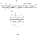
FIG. 2 is a cross-sectional view ofFIG. 1 . -
FIG. 3 is a plan view of a first electrode according to the present invention. -
FIG. 4 is a plan view of a second electrode according to the present invention. -
FIG. 5 is a side view of a folded electrode assembly according to the present invention. -
FIG. 6 is an enlarged view illustrating a portion 'A' ofFIG. 5 . -
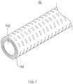
FIG. 7 is a perspective view of the folded electrode assembly according to the present invention. -
FIG. 8 is a cross-sectional view of a secondary battery comprising the electrode assembly according to the present invention. -
FIG. 9 is a flowchart illustrating a method for manufacturing the secondary battery according to the present invention. -
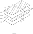
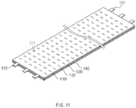
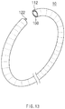
FIGS. 10 to 13 are views illustrating a state of the secondary battery that is manufactured by the method for manufacturing the secondary battery according to the present invention,FIG. 10 is a view illustrating a state before the electrode assembly is stacked,FIG. 11 is a view illustrating a state after the electrode assembly is stacked,FIG. 12 is a folded state of the electrode assembly, andFIG. 13 is a view illustrating the folded secondary battery. - Hereinafter, an embodiment of the present invention will be described in detail with reference to the accompanying drawings in such a manner that the technical idea of the present invention may easily be carried out by a person with ordinary skill in the art to which the invention pertains. The present invention may, however, be embodied in different forms and should not be construed as limited to the embodiments set forth herein. In the drawings, anything unnecessary for describing the present invention will be omitted for clarity, and also like reference numerals in the drawings denote like elements.
- As illustrated in
FIGS. 1 and2 , anelectrode assembly 100 according to the present invention has a structure that is easily folded and bent through a notching part. Theelectrode assembly 100 comprises afirst electrode 110 in which afirst notching part 111 is provided, asecond electrode 120 in which asecond notching part 121 is provided, afirst separator 130 interposed between thefirst electrode 110 and thesecond electrode 120, and asecond separator 140 disposed on a lower portion of thesecond electrode 120, - The
first electrode 110 comprises a non-coating portion having a long sheet shape and a first electrode active material layer. Here, thefirst notching part 111 is provided in a surface of thefirst electrode 110, and thefirst electrode 110 is folded and bent through the firstnotching part 111. - For example, referring to
FIG. 3 , thefirst notching part 111 is provided in plurality in a longitudinal direction of thefirst electrode 110, and the plurality offirst notching parts 111 are spaced the same interval from each other. That is, the portions, at which the plurality offirst notching parts 111 are disposed, may be easily folded to bend the first electrode 110 (seeFIG. 5 ). Particularly, when the number offirst notching parts 111 increases, thefirst electrode 110 may be bent in a shape close to a circular shape. When the number offirst notching parts 111 decreases, thefirst electrode 110 may be bent in at least triangular shape. Thus, thefirst electrode 110 may be deformed in various shapes. - Here, referring to
FIG. 3 , the first notchingpart 111 may be provided in plurality in a width direction (a vertical direction when viewed inFIG. 3 ) in addition to the longitudinal direction (a horizontal direction when viewed inFIG. 3 ) of thefirst electrode 110. That is, thefirst electrode 110 may be folded and bent in the longitudinal direction and also folded and bent in the width direction. Thus, thefirst electrode 110 may be deformed in various shapes. - The first notching
part 111 may be formed in the surface of thefirst electrode 110 in a punching manner. That is, the first notchingpart 111 formed in the punching manner may be easily processed and reduce an area and strength of thefirst electrode 110 so that thefirst electrode 110 is easily bent. - The first notching
part 111 may be lengthily disposed in the width direction of thefirst electrode 110 to more reduce the strength of thefirst electrode 110 in the width direction, and thus, thefirst electrode 110 may be more easily folded and bent in a ring shape. - As described above, since the plurality of first notching
parts 111 is provided in the surface of thefirst electrode 110, thefirst electrode 110 may be easily folded and bent in the horizontal or vertical direction. - The
second electrode 120 comprises a non-coating portion having a long sheet shape and a second electrode active material layer. Here, the second notchingpart 121 is provided in a surface of thesecond electrode 120, and thesecond electrode 120 is folded and bent through the second notchingpart 121. - For example, referring to
FIG. 4 , the second notchingpart 121 is provided in plurality in a longitudinal direction of thesecond electrode 120, and the plurality of second notchingparts 121 are spaced the same interval from each other. That is, the portions, at which the plurality of second notchingparts 121 are provided, may be easily folded to bend thefirst electrode 120 as illustrated inFIG. 5 . Particularly, when the number of second notchingparts 121 increases, thesecond electrode 120 may be bent in a shape close to a circular shape. When the number of second notchingparts 121 decreases, thesecond electrode 120 may be bent in at least triangular shape. Thus, thesecond electrode 120 may be deformed in various shapes. - Here, referring to
FIG. 4 , the second notchingpart 121 may be provided in plurality in a width direction (the vertical direction when viewed inFIG. 4 ) in addition to the longitudinal direction (the horizontal direction when viewed inFIG. 4 ) of thesecond electrode 120. That is, thesecond electrode 120 may be folded and bent in the longitudinal direction and also folded and bent in the width direction. Thus, thesecond electrode 120 may be deformed in various shapes. - The second notching
part 121 may be formed in the surface of thesecond electrode 120 in a punching manner. That is, the second notchingpart 121 formed in the punching manner may be easily processed and reduce an area and strength of thesecond electrode 120 so that thesecond electrode 120 is easily bent. - The second notching
part 121 may be lengthily disposed in the width direction of thesecond electrode 120 to more reduce the strength of thesecond electrode 120 in the width direction, and thus, thesecond electrode 120 may be more easily folded and bent in a ring shape. - As described above, since the plurality of second notching
parts 120 is provided in the surface of thesecond electrode 121, thesecond electrode 120 may be easily folded and bent in the horizontal or vertical direction. - The first notching
part 111 and the second notchingpart 121 are disposed to correspond to each other. That is, referring toFIG. 5 , the first and second notchingparts second electrodes second electrodes parts - Each of the first and second notching
parts second electrodes parts parts parts parts - As illustrated in
FIG. 5 , first andsecond electrode tabs second electrodes first electrode tab 112 is disposed on a left end that is one side of thefirst electrode 110 as illustrated inFIG. 3 , and thesecond electrode tab 122 is disposed on a right end that is the other side of thesecond electrode 120 as illustrated inFIG. 4 . - Referring to
FIG. 5 , when the first andsecond electrodes second electrode tabs second electrode tabs - The first and
second separators second electrodes second separators second electrodes - Referring to
FIGS. 5 and6 , theelectrode assembly 100 comprising the above-described constituents may have a structure in which thefirst electrode 110, thefirst separator 130, thesecond electrode 120, and thesecond separator 140 are sequentially stacked. When the stackedelectrode assembly 100 is folded in the ring shape, the first and second notchingparts second electrodes - The
electrode assembly 100, in which thefirst electrode 110, thefirst separator 130, thesecond electrode 120, and thesecond separator 140 are sequentially stacked, may be folded in a roll shape along the width direction and thus provided as thecylindrical electrode assembly 100 as illustrated inFIG. 7 . - That is, as illustrated in
FIG. 7 , when the foldedelectrode assembly 100 is bent in the ring shape, theelectrode assembly 100 may be folded by the first and second notchingparts second electrodes parts electrode assembly 100, theelectrode assembly 100 may be bent in all directions. - A
core 150 is disposed at a center of the foldedelectrode assembly 100. Thecore 150 has a long bar shape and is inserted into the center of the foldedelectrode assembly 100. - Here, the
core 150 may be made of a material having flexibility, insulation, and heat-resistance. That is, thecore 150 supports the foldedelectrode assembly 100 so that theelectrode assembly 100 is easily folded up to a predetermined angle, but prevented from excessively folded at an angle that is greater than the predetermined angle. That is, thecore 150 may support the foldedelectrode assembly 100 so that theelectrode assembly 100 is not completely folded to prevent the short circuit from occurring. - Thus, the folded
electrode assembly 100 may be folded and bent in the all direction and thus deformable in more various shapes. As a result, theelectrode assembly 100 may be applied to products manufactured in various shapes because theelectrode assembly 100 is folded or bent to match the shapes of the products. - The folded
electrode assembly 100 comprising the above-described constituents may be provided with aninsulator 200 on the outer circumferential surface thereof to constitute asecondary battery 10. - That is, the
secondary battery 10 according to the present invention comprises the foldedelectrode assembly 100 and theinsulator 200 coated to surround the outer circumferential surface of the foldedelectrode assembly 100. Thus, thesecondary battery 10 that is deformable in various shapes may be provided. - A method for manufacturing the secondary battery comprising the above-described constituents will be described below.
- As illustrated in
FIG. 9 , a method for manufacturing a folding type secondary battery according to the present invention comprises: a step (a) of processing a plurality of first or second notching parts in a surface of a first or second electrode; a step (b) of interposing a first separator between the first and second electrodes and stacking a second separator on a lower portion of the second electrode to manufacture an electrode sheet; a step (c) of folding the electrode sheet in a width direction to manufacture an electrode assembly; and a step (d) of forming an insulator on the outside of the electrode assembly to surround the electrode assembly. - As illustrated in
FIG. 10 , in the step (a), the first andsecond electrodes second electrode tabs part second electrode - That is, the surface of the first or
second electrode part part second electrode - Particularly, in the step (a), the first or second notching
part second electrode - Also, in the step (a), the first and second notching
parts second electrodes - Also, in the step (a), the plurality of first or second notching
parts second electrode second electrode - As illustrated in
FIG. 11 , in the step (b), thefirst separator 130 is interposed between thefirst electrode 110 and thesecond electrode 120, and thesecond separator 140 is stacked on the lower portion of thesecond electrode 120 to manufacture the electrode sheet. As a result, the electrode sheet has a structure in which the first electrode, the first separator, the second electrode, and the second separator are sequentially stacked. - As illustrated in
FIGS. 12 and13 , in the step (c), the electrode sheet is folded along the width direction to manufacture theelectrode assembly 100. Here, acore 150 is inserted into a center of theelectrode assembly 100. That is, in the step (c), the electrode sheet is folded along the width direction to surround thecore 150 having a long bar shape and thereby to manufacture theelectrode assembly 100, thereby preventing theelectrode assembly 100 from being easily bent or excessively folded. - In the step (d), an
insulator 200 surrounding theelectrode assembly 100 is formed on the outside of theelectrode assembly 100. When the process is completed as described above, thesecondary battery 10 may be completely manufactured. - Therefore, as illustrated in
FIG. 13 , the foldedsecondary battery 10 according to the present invention may be easily folded and bent in the ring shape and thus deformed in various shapes. - Accordingly, the scope of the present invention is defined by the appended claims rather than the foregoing description and the exemplary embodiments described therein. Various modifications made within the meaning of an equivalent of the claims of the invention and within the claims are to be regarded to be in the scope of the present invention.
Claims (16)
- A secondary battery comprising an electrode assembly,
wherein the electrode assembly comprises:a first electrode in which a first notching part is provided;a second electrode in which a second notching part is provided;a first separator interposed between the first electrode and the second electrode; anda second separator disposed on a lower portion of the second electrode,wherein the electrode assembly is folded in a width direction in a state in which the first electrode, the first separator, the second electrode, and the second separator are sequentially stacked and folded and bent through the first and second notching parts. - The secondary battery of claim 1, wherein each of the first and second notching parts is provided in plurality, and the plurality of first or second notching parts are disposed to be spaced apart from each other in a longitudinal direction of the first or second electrode.
- The secondary battery of claim 1, wherein each of the first and second notching parts is provided in plurality, and the plurality of first or second notching parts are disposed to be spaced apart from each other in the width direction of the first or second electrode.
- The secondary battery of claim 1, wherein the first and second notching parts are disposed to correspond to each other.
- The secondary battery of claim 1, wherein the first or second notching part is formed in a punching manner.
- The secondary battery of claim 1, wherein the first or second notching part has one of circular, rectangular, and polygonal shapes.
- The secondary battery of claim 1, wherein the first or second notching part is lengthily disposed in the width direction of the first or second electrode.
- The secondary battery of claim 1, wherein a first electrode tab is disposed on one end of the first electrode,
a second tab is disposed on the other end of the second electrode, and
when the folded electrode assembly is bent, the first and second electrode tabs meet to face each other. - The secondary battery of claim 1, wherein a core is provided in a center of the folded electrode assembly.
- The secondary battery of claim 9, wherein the core is made of a material having flexibility and insulation.
- The secondary battery of claim 1, wherein an insulator is disposed on the outside of the folded electrode assembly.
- A method for manufacturing a secondary battery, the method comprising:a step (a) of processing a plurality of first or second notching parts in a surface of first or second electrode;a step (b) of interposing a first separator between the first electrode and the second electrode and stacking a second separator on a lower portion of the second electrode to manufacture an electrode sheet;a step (c) of folding the electrode sheet along a width direction to manufacture an electrode assembly; anda step (d) of forming an insulation surrounding the electrode assembly on the outside of the electrode assembly.
- The method of claim 12, wherein, in the step (a), the plurality of first or second notching parts are formed to be spaced apart from each other in at least one of longitudinal and width directions of the first or second electrode.
- The method of claim 12, wherein the first and second notching parts are formed to correspond to each other.
- The method of claim 12, wherein, in the step (c), the electrode sheet is folded in the width direction to surround a core having a long bar shape, thereby manufacturing the electrode assembly.
- The method of claim 12, wherein a first electrode tab is formed on one end of the first electrode, and
a second tab is formed on the other end of the second electrode.
Applications Claiming Priority (2)
| Application Number | Priority Date | Filing Date | Title |
|---|---|---|---|
| KR1020150095444A KR101940149B1 (en) | 2015-07-03 | 2015-07-03 | Secondary battery and manufacturing method of thereof |
| PCT/KR2016/007072 WO2017007176A1 (en) | 2015-07-03 | 2016-06-30 | Secondary battery and method for preparing same |
Publications (3)
| Publication Number | Publication Date |
|---|---|
| EP3264511A1 true EP3264511A1 (en) | 2018-01-03 |
| EP3264511A4 EP3264511A4 (en) | 2018-06-13 |
| EP3264511B1 EP3264511B1 (en) | 2023-06-07 |
Family
ID=57685720
Family Applications (1)
| Application Number | Title | Priority Date | Filing Date |
|---|---|---|---|
| EP16821582.0A Active EP3264511B1 (en) | 2015-07-03 | 2016-06-30 | Secondary battery and manufacturing method thereof |
Country Status (6)
| Country | Link |
|---|---|
| US (1) | US10541404B2 (en) |
| EP (1) | EP3264511B1 (en) |
| JP (1) | JP6692901B2 (en) |
| KR (1) | KR101940149B1 (en) |
| CN (1) | CN107534154B (en) |
| WO (1) | WO2017007176A1 (en) |
Families Citing this family (3)
| Publication number | Priority date | Publication date | Assignee | Title |
|---|---|---|---|---|
| KR102261183B1 (en) | 2017-11-22 | 2021-06-07 | 주식회사 엘지에너지솔루션 | Cable type battery |
| KR102413816B1 (en) * | 2020-04-13 | 2022-06-29 | 주식회사 클레버 | Prop Device for Terrace Folding of Secondary Battery Cell |
| KR102852651B1 (en) * | 2021-02-23 | 2025-08-29 | 주식회사 엘지에너지솔루션 | Transport apparatus for unit cell |
Family Cites Families (22)
| Publication number | Priority date | Publication date | Assignee | Title |
|---|---|---|---|---|
| JPH06260172A (en) | 1993-03-02 | 1994-09-16 | Japan Storage Battery Co Ltd | Square form lithium battery |
| JPH09129223A (en) * | 1995-10-30 | 1997-05-16 | Shin Kobe Electric Mach Co Ltd | Electrodes for wound batteries |
| JP2001006749A (en) * | 1999-06-25 | 2001-01-12 | Toyota Central Res & Dev Lab Inc | Lithium secondary battery |
| US20020055768A1 (en) * | 1999-11-24 | 2002-05-09 | Kathy Hess | Method of manufacturing a thin-layered, endovascular, polymer-covered stent device |
| JP2001266894A (en) | 2000-03-22 | 2001-09-28 | Sony Corp | Battery electrode and non-aqueous electrolyte battery using the same |
| US7163762B2 (en) | 2000-11-21 | 2007-01-16 | Sony Corporation | Polymer electrolyte battery and method of producing same |
| JP2002222664A (en) * | 2001-01-25 | 2002-08-09 | Tookado:Kk | Lithium polymer battery |
| KR100542214B1 (en) * | 2003-10-31 | 2006-01-10 | 삼성에스디아이 주식회사 | Method for producing electrode for lithium secondary battery and lithium secondary battery comprising this electrode |
| JP4640354B2 (en) | 2007-02-26 | 2011-03-02 | ソニー株式会社 | ELECTRODE STRUCTURE AND METHOD FOR MANUFACTURING THE SAME |
| JP2010067443A (en) * | 2008-09-10 | 2010-03-25 | Sumitomo Electric Ind Ltd | Battery and manufacturing method therefor |
| JP5862563B2 (en) * | 2010-07-03 | 2016-02-16 | 株式会社Gsユアサ | Battery and battery manufacturing method |
| KR101256641B1 (en) * | 2010-11-02 | 2013-04-18 | 삼성에스디아이 주식회사 | Positive active material for lithium secondary battery and method for thereof |
| CN103430370B (en) | 2011-03-11 | 2015-12-23 | 株式会社Lg化学 | Cable type secondary battery |
| KR101455165B1 (en) * | 2011-11-19 | 2014-10-27 | 주식회사 엘지화학 | Electrode Assembly of Improved Stability and Secondary Battery the Same |
| JP6095961B2 (en) * | 2011-12-06 | 2017-03-15 | 株式会社半導体エネルギー研究所 | Square lithium secondary battery |
| KR101383629B1 (en) | 2012-03-14 | 2014-04-14 | 주식회사 엘지화학 | Battery Cell Havig Through Hole and Battery Pack Comprising The Same |
| JP2013218804A (en) | 2012-04-04 | 2013-10-24 | Gs Yuasa Corp | Electrode body, storage element, and manufacturing method of electrode body |
| KR101617495B1 (en) | 2013-03-04 | 2016-05-03 | 주식회사 엘지화학 | Method for Preparing a Jelly-Roll Type Electrode Assembly and a Secondary Battery |
| KR101465164B1 (en) | 2013-05-07 | 2014-11-25 | 주식회사 엘지화학 | Cable-Type Secondary Battery |
| EP2806476A1 (en) | 2013-05-22 | 2014-11-26 | The Swatch Group Research and Development Ltd. | Electrochemical cell |
| US20140370347A1 (en) * | 2013-06-14 | 2014-12-18 | Samsung Sdi Co., Ltd. | Flexible battery |
| JP6361969B2 (en) | 2013-11-15 | 2018-07-25 | 株式会社Gsユアサ | Storage element and storage element module |
-
2015
- 2015-07-03 KR KR1020150095444A patent/KR101940149B1/en active Active
-
2016
- 2016-06-30 US US15/563,206 patent/US10541404B2/en active Active
- 2016-06-30 EP EP16821582.0A patent/EP3264511B1/en active Active
- 2016-06-30 CN CN201680021672.8A patent/CN107534154B/en active Active
- 2016-06-30 JP JP2018519667A patent/JP6692901B2/en active Active
- 2016-06-30 WO PCT/KR2016/007072 patent/WO2017007176A1/en not_active Ceased
Also Published As
| Publication number | Publication date |
|---|---|
| EP3264511A4 (en) | 2018-06-13 |
| KR101940149B1 (en) | 2019-01-18 |
| US10541404B2 (en) | 2020-01-21 |
| JP2018519650A (en) | 2018-07-19 |
| WO2017007176A1 (en) | 2017-01-12 |
| KR20170004721A (en) | 2017-01-11 |
| JP6692901B2 (en) | 2020-05-13 |
| CN107534154B (en) | 2020-11-03 |
| EP3264511B1 (en) | 2023-06-07 |
| US20180090739A1 (en) | 2018-03-29 |
| CN107534154A (en) | 2018-01-02 |
Similar Documents
| Publication | Publication Date | Title |
|---|---|---|
| EP3151306B1 (en) | Rechargeable battery | |
| KR101137372B1 (en) | Method of manufacturing electrode assembly for rechargeable battery | |
| US9577239B2 (en) | Secondary battery having an electrode assembly | |
| KR102249892B1 (en) | Rechargeable battery | |
| KR102235281B1 (en) | Rechargeable battery | |
| CN108428847B (en) | secondary battery | |
| US20150372399A1 (en) | Electric wire with crimp terminal | |
| CN103326056A (en) | Secondary battery | |
| CN109690857A (en) | Stacked electrode assembly and flexible rechargeable battery including it | |
| JP2022540192A (en) | Electrode assembly and battery | |
| US11043669B2 (en) | Electrode and secondary battery comprising the same | |
| EP3264511B1 (en) | Secondary battery and manufacturing method thereof | |
| US20150126062A1 (en) | Connection structure of outer conductor terminal to electric wire | |
| EP3249733A1 (en) | Secondary battery | |
| KR102275331B1 (en) | Rechargeable battery | |
| CN114447342B (en) | Electrochemical device and electronic device | |
| CN117199549A (en) | Battery cell, energy storage device and electronic equipment | |
| WO2020040866A1 (en) | Folding tab for ultra-thin battery cell connection | |
| EP3514877A1 (en) | Electrode assembly and manufacturing method for electrode assembly | |
| EP3190644A1 (en) | Lead tab of fibrous secondary battery | |
| CN220797021U (en) | Battery cell, energy storage device and electronic device | |
| CN217507687U (en) | Crimping structure snap ring terminal with three crimping wings | |
| KR102078800B1 (en) | Secondary battery and method for manufacturing the same | |
| CN112868121B (en) | Cells, Batteries and Electronic Devices | |
| KR102723446B1 (en) | Secondary battery and manufacturing method thereof |
Legal Events
| Date | Code | Title | Description |
|---|---|---|---|
| STAA | Information on the status of an ep patent application or granted ep patent |
Free format text: STATUS: THE INTERNATIONAL PUBLICATION HAS BEEN MADE |
|
| PUAI | Public reference made under article 153(3) epc to a published international application that has entered the european phase |
Free format text: ORIGINAL CODE: 0009012 |
|
| STAA | Information on the status of an ep patent application or granted ep patent |
Free format text: STATUS: REQUEST FOR EXAMINATION WAS MADE |
|
| 17P | Request for examination filed |
Effective date: 20170928 |
|
| AK | Designated contracting states |
Kind code of ref document: A1 Designated state(s): AL AT BE BG CH CY CZ DE DK EE ES FI FR GB GR HR HU IE IS IT LI LT LU LV MC MK MT NL NO PL PT RO RS SE SI SK SM TR |
|
| AX | Request for extension of the european patent |
Extension state: BA ME |
|
| RIC1 | Information provided on ipc code assigned before grant |
Ipc: H01M 10/04 20060101ALI20180502BHEP Ipc: H01M 4/74 20060101AFI20180502BHEP Ipc: H01M 2/26 20060101ALI20180502BHEP |
|
| A4 | Supplementary search report drawn up and despatched |
Effective date: 20180511 |
|
| DAV | Request for validation of the european patent (deleted) | ||
| DAX | Request for extension of the european patent (deleted) | ||
| STAA | Information on the status of an ep patent application or granted ep patent |
Free format text: STATUS: EXAMINATION IS IN PROGRESS |
|
| 17Q | First examination report despatched |
Effective date: 20201123 |
|
| RAP1 | Party data changed (applicant data changed or rights of an application transferred) |
Owner name: LG ENERGY SOLUTION LTD. |
|
| RAP3 | Party data changed (applicant data changed or rights of an application transferred) |
Owner name: LG ENERGY SOLUTION, LTD. |
|
| REG | Reference to a national code |
Ref country code: DE Ref legal event code: R079 Free format text: PREVIOUS MAIN CLASS: H01M0010040000 Ipc: H01M0004740000 Ref country code: DE Ref legal event code: R079 Ref document number: 602016080076 Country of ref document: DE Free format text: PREVIOUS MAIN CLASS: H01M0010040000 Ipc: H01M0004740000 |
|
| GRAP | Despatch of communication of intention to grant a patent |
Free format text: ORIGINAL CODE: EPIDOSNIGR1 |
|
| STAA | Information on the status of an ep patent application or granted ep patent |
Free format text: STATUS: GRANT OF PATENT IS INTENDED |
|
| RIC1 | Information provided on ipc code assigned before grant |
Ipc: H01M 50/538 20210101ALN20221220BHEP Ipc: H01M 50/54 20210101ALI20221220BHEP Ipc: H01M 10/04 20060101ALI20221220BHEP Ipc: H01M 4/74 20060101AFI20221220BHEP |
|
| INTG | Intention to grant announced |
Effective date: 20230110 |
|
| GRAS | Grant fee paid |
Free format text: ORIGINAL CODE: EPIDOSNIGR3 |
|
| GRAA | (expected) grant |
Free format text: ORIGINAL CODE: 0009210 |
|
| STAA | Information on the status of an ep patent application or granted ep patent |
Free format text: STATUS: THE PATENT HAS BEEN GRANTED |
|
| AK | Designated contracting states |
Kind code of ref document: B1 Designated state(s): AL AT BE BG CH CY CZ DE DK EE ES FI FR GB GR HR HU IE IS IT LI LT LU LV MC MK MT NL NO PL PT RO RS SE SI SK SM TR |
|
| REG | Reference to a national code |
Ref country code: GB Ref legal event code: FG4D |
|
| REG | Reference to a national code |
Ref country code: CH Ref legal event code: EP Ref country code: AT Ref legal event code: REF Ref document number: 1577610 Country of ref document: AT Kind code of ref document: T Effective date: 20230615 |
|
| REG | Reference to a national code |
Ref country code: DE Ref legal event code: R096 Ref document number: 602016080076 Country of ref document: DE |
|
| P01 | Opt-out of the competence of the unified patent court (upc) registered |
Effective date: 20230525 |
|
| REG | Reference to a national code |
Ref country code: LT Ref legal event code: MG9D |
|
| REG | Reference to a national code |
Ref country code: NL Ref legal event code: MP Effective date: 20230607 |
|
| PG25 | Lapsed in a contracting state [announced via postgrant information from national office to epo] |
Ref country code: SE Free format text: LAPSE BECAUSE OF FAILURE TO SUBMIT A TRANSLATION OF THE DESCRIPTION OR TO PAY THE FEE WITHIN THE PRESCRIBED TIME-LIMIT Effective date: 20230607 Ref country code: NO Free format text: LAPSE BECAUSE OF FAILURE TO SUBMIT A TRANSLATION OF THE DESCRIPTION OR TO PAY THE FEE WITHIN THE PRESCRIBED TIME-LIMIT Effective date: 20230907 Ref country code: ES Free format text: LAPSE BECAUSE OF FAILURE TO SUBMIT A TRANSLATION OF THE DESCRIPTION OR TO PAY THE FEE WITHIN THE PRESCRIBED TIME-LIMIT Effective date: 20230607 |
|
| REG | Reference to a national code |
Ref country code: AT Ref legal event code: MK05 Ref document number: 1577610 Country of ref document: AT Kind code of ref document: T Effective date: 20230607 |
|
| PG25 | Lapsed in a contracting state [announced via postgrant information from national office to epo] |
Ref country code: RS Free format text: LAPSE BECAUSE OF FAILURE TO SUBMIT A TRANSLATION OF THE DESCRIPTION OR TO PAY THE FEE WITHIN THE PRESCRIBED TIME-LIMIT Effective date: 20230607 Ref country code: NL Free format text: LAPSE BECAUSE OF FAILURE TO SUBMIT A TRANSLATION OF THE DESCRIPTION OR TO PAY THE FEE WITHIN THE PRESCRIBED TIME-LIMIT Effective date: 20230607 Ref country code: LV Free format text: LAPSE BECAUSE OF FAILURE TO SUBMIT A TRANSLATION OF THE DESCRIPTION OR TO PAY THE FEE WITHIN THE PRESCRIBED TIME-LIMIT Effective date: 20230607 Ref country code: LT Free format text: LAPSE BECAUSE OF FAILURE TO SUBMIT A TRANSLATION OF THE DESCRIPTION OR TO PAY THE FEE WITHIN THE PRESCRIBED TIME-LIMIT Effective date: 20230607 Ref country code: HR Free format text: LAPSE BECAUSE OF FAILURE TO SUBMIT A TRANSLATION OF THE DESCRIPTION OR TO PAY THE FEE WITHIN THE PRESCRIBED TIME-LIMIT Effective date: 20230607 Ref country code: GR Free format text: LAPSE BECAUSE OF FAILURE TO SUBMIT A TRANSLATION OF THE DESCRIPTION OR TO PAY THE FEE WITHIN THE PRESCRIBED TIME-LIMIT Effective date: 20230908 |
|
| PG25 | Lapsed in a contracting state [announced via postgrant information from national office to epo] |
Ref country code: FI Free format text: LAPSE BECAUSE OF FAILURE TO SUBMIT A TRANSLATION OF THE DESCRIPTION OR TO PAY THE FEE WITHIN THE PRESCRIBED TIME-LIMIT Effective date: 20230607 |
|
| PG25 | Lapsed in a contracting state [announced via postgrant information from national office to epo] |
Ref country code: SK Free format text: LAPSE BECAUSE OF FAILURE TO SUBMIT A TRANSLATION OF THE DESCRIPTION OR TO PAY THE FEE WITHIN THE PRESCRIBED TIME-LIMIT Effective date: 20230607 |
|
| PG25 | Lapsed in a contracting state [announced via postgrant information from national office to epo] |
Ref country code: IS Free format text: LAPSE BECAUSE OF FAILURE TO SUBMIT A TRANSLATION OF THE DESCRIPTION OR TO PAY THE FEE WITHIN THE PRESCRIBED TIME-LIMIT Effective date: 20231007 |
|
| PG25 | Lapsed in a contracting state [announced via postgrant information from national office to epo] |
Ref country code: SM Free format text: LAPSE BECAUSE OF FAILURE TO SUBMIT A TRANSLATION OF THE DESCRIPTION OR TO PAY THE FEE WITHIN THE PRESCRIBED TIME-LIMIT Effective date: 20230607 Ref country code: SK Free format text: LAPSE BECAUSE OF FAILURE TO SUBMIT A TRANSLATION OF THE DESCRIPTION OR TO PAY THE FEE WITHIN THE PRESCRIBED TIME-LIMIT Effective date: 20230607 Ref country code: RO Free format text: LAPSE BECAUSE OF FAILURE TO SUBMIT A TRANSLATION OF THE DESCRIPTION OR TO PAY THE FEE WITHIN THE PRESCRIBED TIME-LIMIT Effective date: 20230607 Ref country code: PT Free format text: LAPSE BECAUSE OF FAILURE TO SUBMIT A TRANSLATION OF THE DESCRIPTION OR TO PAY THE FEE WITHIN THE PRESCRIBED TIME-LIMIT Effective date: 20231009 Ref country code: IS Free format text: LAPSE BECAUSE OF FAILURE TO SUBMIT A TRANSLATION OF THE DESCRIPTION OR TO PAY THE FEE WITHIN THE PRESCRIBED TIME-LIMIT Effective date: 20231007 Ref country code: EE Free format text: LAPSE BECAUSE OF FAILURE TO SUBMIT A TRANSLATION OF THE DESCRIPTION OR TO PAY THE FEE WITHIN THE PRESCRIBED TIME-LIMIT Effective date: 20230607 Ref country code: CZ Free format text: LAPSE BECAUSE OF FAILURE TO SUBMIT A TRANSLATION OF THE DESCRIPTION OR TO PAY THE FEE WITHIN THE PRESCRIBED TIME-LIMIT Effective date: 20230607 Ref country code: AT Free format text: LAPSE BECAUSE OF FAILURE TO SUBMIT A TRANSLATION OF THE DESCRIPTION OR TO PAY THE FEE WITHIN THE PRESCRIBED TIME-LIMIT Effective date: 20230607 |
|
| REG | Reference to a national code |
Ref country code: CH Ref legal event code: PL |
|
| REG | Reference to a national code |
Ref country code: BE Ref legal event code: MM Effective date: 20230630 |
|
| PG25 | Lapsed in a contracting state [announced via postgrant information from national office to epo] |
Ref country code: PL Free format text: LAPSE BECAUSE OF FAILURE TO SUBMIT A TRANSLATION OF THE DESCRIPTION OR TO PAY THE FEE WITHIN THE PRESCRIBED TIME-LIMIT Effective date: 20230607 |
|
| PG25 | Lapsed in a contracting state [announced via postgrant information from national office to epo] |
Ref country code: LU Free format text: LAPSE BECAUSE OF NON-PAYMENT OF DUE FEES Effective date: 20230630 |
|
| REG | Reference to a national code |
Ref country code: DE Ref legal event code: R097 Ref document number: 602016080076 Country of ref document: DE |
|
| PG25 | Lapsed in a contracting state [announced via postgrant information from national office to epo] |
Ref country code: MC Free format text: LAPSE BECAUSE OF FAILURE TO SUBMIT A TRANSLATION OF THE DESCRIPTION OR TO PAY THE FEE WITHIN THE PRESCRIBED TIME-LIMIT Effective date: 20230607 |
|
| REG | Reference to a national code |
Ref country code: IE Ref legal event code: MM4A |
|
| PG25 | Lapsed in a contracting state [announced via postgrant information from national office to epo] |
Ref country code: MC Free format text: LAPSE BECAUSE OF FAILURE TO SUBMIT A TRANSLATION OF THE DESCRIPTION OR TO PAY THE FEE WITHIN THE PRESCRIBED TIME-LIMIT Effective date: 20230607 Ref country code: LU Free format text: LAPSE BECAUSE OF NON-PAYMENT OF DUE FEES Effective date: 20230630 |
|
| PLBE | No opposition filed within time limit |
Free format text: ORIGINAL CODE: 0009261 |
|
| STAA | Information on the status of an ep patent application or granted ep patent |
Free format text: STATUS: NO OPPOSITION FILED WITHIN TIME LIMIT |
|
| PG25 | Lapsed in a contracting state [announced via postgrant information from national office to epo] |
Ref country code: IE Free format text: LAPSE BECAUSE OF NON-PAYMENT OF DUE FEES Effective date: 20230630 |
|
| PG25 | Lapsed in a contracting state [announced via postgrant information from national office to epo] |
Ref country code: IE Free format text: LAPSE BECAUSE OF NON-PAYMENT OF DUE FEES Effective date: 20230630 Ref country code: DK Free format text: LAPSE BECAUSE OF FAILURE TO SUBMIT A TRANSLATION OF THE DESCRIPTION OR TO PAY THE FEE WITHIN THE PRESCRIBED TIME-LIMIT Effective date: 20230607 Ref country code: CH Free format text: LAPSE BECAUSE OF NON-PAYMENT OF DUE FEES Effective date: 20230630 |
|
| PG25 | Lapsed in a contracting state [announced via postgrant information from national office to epo] |
Ref country code: SI Free format text: LAPSE BECAUSE OF FAILURE TO SUBMIT A TRANSLATION OF THE DESCRIPTION OR TO PAY THE FEE WITHIN THE PRESCRIBED TIME-LIMIT Effective date: 20230607 |
|
| 26N | No opposition filed |
Effective date: 20240308 |
|
| PG25 | Lapsed in a contracting state [announced via postgrant information from national office to epo] |
Ref country code: SI Free format text: LAPSE BECAUSE OF FAILURE TO SUBMIT A TRANSLATION OF THE DESCRIPTION OR TO PAY THE FEE WITHIN THE PRESCRIBED TIME-LIMIT Effective date: 20230607 Ref country code: IT Free format text: LAPSE BECAUSE OF FAILURE TO SUBMIT A TRANSLATION OF THE DESCRIPTION OR TO PAY THE FEE WITHIN THE PRESCRIBED TIME-LIMIT Effective date: 20230607 Ref country code: BE Free format text: LAPSE BECAUSE OF NON-PAYMENT OF DUE FEES Effective date: 20230630 |
|
| PG25 | Lapsed in a contracting state [announced via postgrant information from national office to epo] |
Ref country code: BG Free format text: LAPSE BECAUSE OF FAILURE TO SUBMIT A TRANSLATION OF THE DESCRIPTION OR TO PAY THE FEE WITHIN THE PRESCRIBED TIME-LIMIT Effective date: 20230607 |
|
| PG25 | Lapsed in a contracting state [announced via postgrant information from national office to epo] |
Ref country code: BG Free format text: LAPSE BECAUSE OF FAILURE TO SUBMIT A TRANSLATION OF THE DESCRIPTION OR TO PAY THE FEE WITHIN THE PRESCRIBED TIME-LIMIT Effective date: 20230607 |
|
| PGFP | Annual fee paid to national office [announced via postgrant information from national office to epo] |
Ref country code: DE Payment date: 20250520 Year of fee payment: 10 |
|
| PGFP | Annual fee paid to national office [announced via postgrant information from national office to epo] |
Ref country code: GB Payment date: 20250520 Year of fee payment: 10 |
|
| PGFP | Annual fee paid to national office [announced via postgrant information from national office to epo] |
Ref country code: FR Payment date: 20250521 Year of fee payment: 10 |
|
| PG25 | Lapsed in a contracting state [announced via postgrant information from national office to epo] |
Ref country code: CY Free format text: LAPSE BECAUSE OF FAILURE TO SUBMIT A TRANSLATION OF THE DESCRIPTION OR TO PAY THE FEE WITHIN THE PRESCRIBED TIME-LIMIT; INVALID AB INITIO Effective date: 20160630 |
|
| PG25 | Lapsed in a contracting state [announced via postgrant information from national office to epo] |
Ref country code: HU Free format text: LAPSE BECAUSE OF FAILURE TO SUBMIT A TRANSLATION OF THE DESCRIPTION OR TO PAY THE FEE WITHIN THE PRESCRIBED TIME-LIMIT; INVALID AB INITIO Effective date: 20160630 |
|
| PG25 | Lapsed in a contracting state [announced via postgrant information from national office to epo] |
Ref country code: TR Free format text: LAPSE BECAUSE OF FAILURE TO SUBMIT A TRANSLATION OF THE DESCRIPTION OR TO PAY THE FEE WITHIN THE PRESCRIBED TIME-LIMIT Effective date: 20230607 |