EP3264463A1 - Circuitry with voltage limiting and capactive enhancement - Google Patents
Circuitry with voltage limiting and capactive enhancement Download PDFInfo
- Publication number
- EP3264463A1 EP3264463A1 EP17171149.2A EP17171149A EP3264463A1 EP 3264463 A1 EP3264463 A1 EP 3264463A1 EP 17171149 A EP17171149 A EP 17171149A EP 3264463 A1 EP3264463 A1 EP 3264463A1
- Authority
- EP
- European Patent Office
- Prior art keywords
- transistor
- source
- voltage
- drain
- trenches
- Prior art date
- Legal status (The legal status is an assumption and is not a legal conclusion. Google has not performed a legal analysis and makes no representation as to the accuracy of the status listed.)
- Granted
Links
Images


Classifications
-
- H—ELECTRICITY
- H10—SEMICONDUCTOR DEVICES; ELECTRIC SOLID-STATE DEVICES NOT OTHERWISE PROVIDED FOR
- H10D—INORGANIC ELECTRIC SEMICONDUCTOR DEVICES
- H10D89/00—Aspects of integrated devices not covered by groups H10D84/00 - H10D88/00
- H10D89/60—Integrated devices comprising arrangements for electrical or thermal protection, e.g. protection circuits against electrostatic discharge [ESD]
- H10D89/601—Integrated devices comprising arrangements for electrical or thermal protection, e.g. protection circuits against electrostatic discharge [ESD] for devices having insulated gate electrodes, e.g. for IGFETs or IGBTs
- H10D89/611—Integrated devices comprising arrangements for electrical or thermal protection, e.g. protection circuits against electrostatic discharge [ESD] for devices having insulated gate electrodes, e.g. for IGFETs or IGBTs using diodes as protective elements
-
- H—ELECTRICITY
- H10—SEMICONDUCTOR DEVICES; ELECTRIC SOLID-STATE DEVICES NOT OTHERWISE PROVIDED FOR
- H10D—INORGANIC ELECTRIC SEMICONDUCTOR DEVICES
- H10D30/00—Field-effect transistors [FET]
- H10D30/60—Insulated-gate field-effect transistors [IGFET]
- H10D30/64—Double-diffused metal-oxide semiconductor [DMOS] FETs
- H10D30/66—Vertical DMOS [VDMOS] FETs
- H10D30/668—Vertical DMOS [VDMOS] FETs having trench gate electrodes, e.g. UMOS transistors
-
- H—ELECTRICITY
- H10—SEMICONDUCTOR DEVICES; ELECTRIC SOLID-STATE DEVICES NOT OTHERWISE PROVIDED FOR
- H10D—INORGANIC ELECTRIC SEMICONDUCTOR DEVICES
- H10D62/00—Semiconductor bodies, or regions thereof, of devices having potential barriers
- H10D62/10—Shapes, relative sizes or dispositions of the regions of the semiconductor bodies; Shapes of the semiconductor bodies
- H10D62/102—Constructional design considerations for preventing surface leakage or controlling electric field concentration
- H10D62/103—Constructional design considerations for preventing surface leakage or controlling electric field concentration for increasing or controlling the breakdown voltage of reverse-biased devices
- H10D62/105—Constructional design considerations for preventing surface leakage or controlling electric field concentration for increasing or controlling the breakdown voltage of reverse-biased devices by having particular doping profiles, shapes or arrangements of PN junctions; by having supplementary regions, e.g. junction termination extension [JTE]
- H10D62/108—Constructional design considerations for preventing surface leakage or controlling electric field concentration for increasing or controlling the breakdown voltage of reverse-biased devices by having particular doping profiles, shapes or arrangements of PN junctions; by having supplementary regions, e.g. junction termination extension [JTE] having localised breakdown regions, e.g. built-in avalanching regions
-
- H—ELECTRICITY
- H10—SEMICONDUCTOR DEVICES; ELECTRIC SOLID-STATE DEVICES NOT OTHERWISE PROVIDED FOR
- H10D—INORGANIC ELECTRIC SEMICONDUCTOR DEVICES
- H10D62/00—Semiconductor bodies, or regions thereof, of devices having potential barriers
- H10D62/10—Shapes, relative sizes or dispositions of the regions of the semiconductor bodies; Shapes of the semiconductor bodies
- H10D62/102—Constructional design considerations for preventing surface leakage or controlling electric field concentration
- H10D62/103—Constructional design considerations for preventing surface leakage or controlling electric field concentration for increasing or controlling the breakdown voltage of reverse-biased devices
- H10D62/105—Constructional design considerations for preventing surface leakage or controlling electric field concentration for increasing or controlling the breakdown voltage of reverse-biased devices by having particular doping profiles, shapes or arrangements of PN junctions; by having supplementary regions, e.g. junction termination extension [JTE]
- H10D62/109—Reduced surface field [RESURF] PN junction structures
-
- H—ELECTRICITY
- H10—SEMICONDUCTOR DEVICES; ELECTRIC SOLID-STATE DEVICES NOT OTHERWISE PROVIDED FOR
- H10D—INORGANIC ELECTRIC SEMICONDUCTOR DEVICES
- H10D84/00—Integrated devices formed in or on semiconductor substrates that comprise only semiconducting layers, e.g. on Si wafers or on GaAs-on-Si wafers
- H10D84/80—Integrated devices formed in or on semiconductor substrates that comprise only semiconducting layers, e.g. on Si wafers or on GaAs-on-Si wafers characterised by the integration of at least one component covered by groups H10D12/00 or H10D30/00, e.g. integration of IGFETs
- H10D84/811—Combinations of field-effect devices and one or more diodes, capacitors or resistors
-
- H—ELECTRICITY
- H10—SEMICONDUCTOR DEVICES; ELECTRIC SOLID-STATE DEVICES NOT OTHERWISE PROVIDED FOR
- H10D—INORGANIC ELECTRIC SEMICONDUCTOR DEVICES
- H10D89/00—Aspects of integrated devices not covered by groups H10D84/00 - H10D88/00
- H10D89/60—Integrated devices comprising arrangements for electrical or thermal protection, e.g. protection circuits against electrostatic discharge [ESD]
- H10D89/601—Integrated devices comprising arrangements for electrical or thermal protection, e.g. protection circuits against electrostatic discharge [ESD] for devices having insulated gate electrodes, e.g. for IGFETs or IGBTs
- H10D89/911—Integrated devices comprising arrangements for electrical or thermal protection, e.g. protection circuits against electrostatic discharge [ESD] for devices having insulated gate electrodes, e.g. for IGFETs or IGBTs using passive elements as protective elements
-
- H—ELECTRICITY
- H10—SEMICONDUCTOR DEVICES; ELECTRIC SOLID-STATE DEVICES NOT OTHERWISE PROVIDED FOR
- H10W—GENERIC PACKAGES, INTERCONNECTIONS, CONNECTORS OR OTHER CONSTRUCTIONAL DETAILS OF DEVICES COVERED BY CLASS H10
- H10W20/00—Interconnections in chips, wafers or substrates
- H10W20/01—Manufacture or treatment
- H10W20/031—Manufacture or treatment of conductive parts of the interconnections
- H10W20/056—Manufacture or treatment of conductive parts of the interconnections by filling conductive material into holes, grooves or trenches
-
- H—ELECTRICITY
- H10—SEMICONDUCTOR DEVICES; ELECTRIC SOLID-STATE DEVICES NOT OTHERWISE PROVIDED FOR
- H10D—INORGANIC ELECTRIC SEMICONDUCTOR DEVICES
- H10D30/00—Field-effect transistors [FET]
- H10D30/60—Insulated-gate field-effect transistors [IGFET]
- H10D30/611—Insulated-gate field-effect transistors [IGFET] having multiple independently-addressable gate electrodes influencing the same channel
- H10D30/615—Insulated-gate field-effect transistors [IGFET] having multiple independently-addressable gate electrodes influencing the same channel comprising a MOS gate electrode and at least one non-MOS gate electrode
-
- H—ELECTRICITY
- H10—SEMICONDUCTOR DEVICES; ELECTRIC SOLID-STATE DEVICES NOT OTHERWISE PROVIDED FOR
- H10D—INORGANIC ELECTRIC SEMICONDUCTOR DEVICES
- H10D62/00—Semiconductor bodies, or regions thereof, of devices having potential barriers
- H10D62/10—Shapes, relative sizes or dispositions of the regions of the semiconductor bodies; Shapes of the semiconductor bodies
- H10D62/102—Constructional design considerations for preventing surface leakage or controlling electric field concentration
- H10D62/103—Constructional design considerations for preventing surface leakage or controlling electric field concentration for increasing or controlling the breakdown voltage of reverse-biased devices
- H10D62/105—Constructional design considerations for preventing surface leakage or controlling electric field concentration for increasing or controlling the breakdown voltage of reverse-biased devices by having particular doping profiles, shapes or arrangements of PN junctions; by having supplementary regions, e.g. junction termination extension [JTE]
- H10D62/109—Reduced surface field [RESURF] PN junction structures
- H10D62/111—Multiple RESURF structures, e.g. double RESURF or 3D-RESURF structures
-
- H—ELECTRICITY
- H10—SEMICONDUCTOR DEVICES; ELECTRIC SOLID-STATE DEVICES NOT OTHERWISE PROVIDED FOR
- H10D—INORGANIC ELECTRIC SEMICONDUCTOR DEVICES
- H10D62/00—Semiconductor bodies, or regions thereof, of devices having potential barriers
- H10D62/80—Semiconductor bodies, or regions thereof, of devices having potential barriers characterised by the materials
- H10D62/83—Semiconductor bodies, or regions thereof, of devices having potential barriers characterised by the materials being Group IV materials, e.g. B-doped Si or undoped Ge
- H10D62/832—Semiconductor bodies, or regions thereof, of devices having potential barriers characterised by the materials being Group IV materials, e.g. B-doped Si or undoped Ge being Group IV materials comprising two or more elements, e.g. SiGe
- H10D62/8325—Silicon carbide
-
- H—ELECTRICITY
- H10—SEMICONDUCTOR DEVICES; ELECTRIC SOLID-STATE DEVICES NOT OTHERWISE PROVIDED FOR
- H10D—INORGANIC ELECTRIC SEMICONDUCTOR DEVICES
- H10D62/00—Semiconductor bodies, or regions thereof, of devices having potential barriers
- H10D62/80—Semiconductor bodies, or regions thereof, of devices having potential barriers characterised by the materials
- H10D62/85—Semiconductor bodies, or regions thereof, of devices having potential barriers characterised by the materials being Group III-V materials, e.g. GaAs
- H10D62/8503—Nitride Group III-V materials, e.g. AlN or GaN
-
- H—ELECTRICITY
- H10—SEMICONDUCTOR DEVICES; ELECTRIC SOLID-STATE DEVICES NOT OTHERWISE PROVIDED FOR
- H10D—INORGANIC ELECTRIC SEMICONDUCTOR DEVICES
- H10D64/00—Electrodes of devices having potential barriers
- H10D64/20—Electrodes characterised by their shapes, relative sizes or dispositions
- H10D64/23—Electrodes carrying the current to be rectified, amplified, oscillated or switched, e.g. sources, drains, anodes or cathodes
- H10D64/251—Source or drain electrodes for field-effect devices
- H10D64/256—Source or drain electrodes for field-effect devices for lateral devices wherein the source or drain electrodes are recessed in semiconductor bodies
-
- H—ELECTRICITY
- H10—SEMICONDUCTOR DEVICES; ELECTRIC SOLID-STATE DEVICES NOT OTHERWISE PROVIDED FOR
- H10D—INORGANIC ELECTRIC SEMICONDUCTOR DEVICES
- H10D84/00—Integrated devices formed in or on semiconductor substrates that comprise only semiconducting layers, e.g. on Si wafers or on GaAs-on-Si wafers
- H10D84/80—Integrated devices formed in or on semiconductor substrates that comprise only semiconducting layers, e.g. on Si wafers or on GaAs-on-Si wafers characterised by the integration of at least one component covered by groups H10D12/00 or H10D30/00, e.g. integration of IGFETs
- H10D84/811—Combinations of field-effect devices and one or more diodes, capacitors or resistors
- H10D84/813—Combinations of field-effect devices and capacitor only
Definitions
- aspects of various embodiments are directed to circuits providing voltage clamping and capacitance, such as may be implemented for controlling high voltage devices.
- switches can be desirably used with related circuitry.
- a normally on device transistor
- a normally on device transistor
- One such approach involves using a cascode arrangement with a low voltage FET (field effect transistor) coupled to a high voltage device to provide a controlling gate voltage.
- Various example embodiments are directed to issues such as those addressed above and/or others which may become apparent from the following disclosure concerning the operation of transistor circuits, such as those involving high voltage transistors.
- normally on transistors are controlled using a low-voltage transistor with enhanced capacitance and mitigation of avalanche breakdown.
- aspects of the present disclosure involve the use of semiconductor structures that provide enhanced capacitance and avalanche breakdown control. Such aspects may be implemented with doped regions separated by trenches, which can further be formed in process steps shared with the formation of the transistors themselves.
- an apparatus in accordance with a particular embodiment, includes a cascode circuit having first and second transistors each having a gate, a source, a channel and drain, with the drain of the second transistor electrically connected to the source of the first transistor.
- the second transistor is operable and connected to control the first transistor in an off state by applying a voltage to the gate thereof.
- the apparatus also includes a plurality of conductive trenches and one or more doped regions, between adjacent ones of the conductive trenches and providing a p-n junction.
- the conductive trenches are configured and arranged with the doped regions to provide capacitance across the source and the drain of the second transistor, and mitigate avalanche breakdown of the second transistor by restricting voltage at one of the source and the drain of the second transistor (e.g., by clamping voltage).
- First and second transistors are provided for a cascode circuit, each having a gate, a source, a channel and a drain, with the drain of the second transistor electrically connected to the source of the first transistor.
- a plurality of conductive trenches along with one or more doped regions between each adjacent trench are connected to the source and drain of the second transistor.
- the second transistor is utilized for controlling the first transistor in an off state by applying a voltage to the gate of the first transistor, and the conductive trenches and the doped regions are used to both provide capacitance across the source and the drain of the second transistor and mitigate avalanche breakdown of the second transistor.
- Avalanche breakdown can be mitigated in this context by limiting, or clamping, voltage at one of the source and the drain of the second transistor.
- an apparatus in other specific example embodiments, includes a cascode circuit, a capacitor circuit and a clamp diode circuit.
- the cascode circuit includes a high-voltage GaN transistor having a gate, a source, a drain and a channel that connects its source and drain.
- the cascode circuit also includes a low-voltage FET having a gate, a source connected to the gate of the high-voltage GaN transistor, a drain connected to the source of the high-voltage GaN transistor, and a channel that connects its source and drain.
- the capacitor and clamp diode circuits are connected to the source and to the drain of the low-voltage FET transistor.
- the low-voltage FET controls the high-voltage GaN transistor in an OFF state by applying the voltage at its source to the gate of the high-voltage GaN transistor, while the capacitor and the clamp diode provide capacitance across the source and the drain of the low-voltage FET, and mitigate avalanche breakdown of the low-voltage FET by clamping voltage across the source and the drain.
- an apparatus comprises a transistor having a gate, a source, a channel and a drain; and a plurality of conductive trenches and at least one doped region that is between each adjacent pair of the conductive trenches and that is configured to provide a p-n junction, wherein the plurality of conductive trenches and at least one doped region are configured and arranged to provide capacitance across the source and the drain and to mitigate avalanche breakdown of the transistor by restricting a voltage level at the source or the drain.
- the drain is electrically coupled to a source of a further transistor in a cascode arrangement, and wherein said transistor is configured and arranged to control the further transistor in an off state by coupling a voltage from the source of said transistor to a gate of the cascode transistor.
- circuitry operable with a low-voltage switch provides additional drain-source capacitance for the switch as well as clamping functions.
- Such circuitry may be implemented with a normally on switch or transistor (e.g., at a source of such a normally ON high-voltage switch and operable to turn the high-voltage switch off).
- Normally on transistors are transistors that are on (conductive) in the absence of a gate voltage. While not necessarily so limited, various aspects may be appreciated through the following discussion of non-limiting examples which use exemplary contexts.
- the additional capacitance/clamping functions illustrated with low voltage switches may be utilized with other circuitry shown herein.
- the additional capacitance/clamping functions (and related circuitry) can be utilized with circuitry in addition and/or as an alternative to high voltage input switches as shown in the figures, such as with implementation for a variety of different types of circuits.
- Various embodiments are directed to providing enhanced Coss (output or drain-source capacitance) and voltage clamp functions with a circuit/spacing construction that fulfils both of these roles.
- spacing between the circuitry and material (e.g., insulating) therein is set to fine tune clamping voltage.
- Such embodiments may be implemented with a normally ON transistor coupled to a low-voltage transistor to which the enhanced Coss is provided.
- a GaN (gallium nitride) normally ON transistor can be implemented with a low voltage FET (such as a MOSFET) with the enhanced Coss and voltage clamp.
- Certain embodiments are directed a structure that functions as both additional capacitance and a clamp diode, to provide enhanced Coss and voltage clamping as noted above.
- a series of deep trenches can be constructed to provide enhanced Coss using the same process that is used for edge terminations in low voltage devices on the same die.
- the trenches are connected to the source of a FET as above, which provide the enhanced/additional Coss.
- the trenches are also used with a p-body implant between each trench (e.g., carried out with a p-body implant for main structure) to define a diode between a series of these trenches.
- the breakdown voltage of such a structure is tuned to a desired value in order to provide a desired function, such as to protect the gate of a high voltage device such as a GaN device controlled by the FET and/or prevent the FET from avalanching.
- additional implants e.g., p or n-type
- the distance between the deep trenches is varied to set the breakdown voltage.
- contacts with the deep trenches are defined to set the breakdown voltage, such as by providing less contact and/or contact to fewer trenches in a series of the trenches.
- inventions employ combinations of two or more of the above, such as by adding implants and modifying deep trench distances, to tune breakdown voltage.
- Further approaches to setting breakdown voltage may include one or more of the following, which may also be implemented with one or more of the above: setting/changing trench depth (e.g., with capacitance being modified with trenches deeper than adjacent drift regions), varying drift region thickness, varying dopant concentration in one or more regions, and changing insulator thickness within the trenches.
- Various approaches herein may be implemented, for example, with low-voltage MOSFETs that may use RESURF (reduced surface field) principles to achieve a high breakdown voltage. For instance, the distance between the deep trenches can be increased (relative to an original design) to reduce the amount of RESURF in the structure (e.g., as shown in Figure 4 ). Accordingly, various aspects involve circuitry and/or related systems/apparatuses that employ a voltage clamp in a cascode configuration (e.g., with a low voltage device), which utilizes a RESURF effect between two isolation trenches. This approach can be implemented to protect low voltage MOSFETs and gate of a connected switch (such as a GaN transistor) from damage due to repetitive avalanche. The voltage clamp also adds additional output capacitance which can be used to protect the device during voltage transients.
- RESURF reduced surface field
- a low-voltage MOSFET as characterized above is placed in the source of a high voltage device, in a cascode arrangement.
- the high voltage device may, for example, include a GaN HEMT (high electron mobility transistor) or an SiC JFET (silicon carbide junction gate field-effect transistor).
- a negative gate voltage is created in the normally on high voltage device, which turns (or maintains) it off (e.g., with the difference between the gate and the source (Vg-Vs) of the low-voltage MOSFET device being negative).
- VDS drain-source voltage
- Vx C DS GaN ⁇ V d ⁇ C OSS MOS + C GS GaN ⁇ V th GaN C DS GaN + C OSS MOS + C GS GaN
- Vx is the drain-source voltage of the MOSFET
- C DS(GaN) is the drain-source capacitance of the GaN HEMT
- V d is the maximum voltage rating of the GaN HEMT
- C GS(GAN) is the gate source voltage of the GaN HEMT
- V th(GAN) is the threshold voltage of the GaN HEMT.
- Vx is dependent on the maximum voltage rating of the connected device (Vd); the threshold voltage V th(GAN) of the normally on (e.g., GaN) device (note since this is negative, the last term in the formula above will be a positive value); and the capacitances of the two devices C DS(GaN) , C GS(CAN) , and C OSS(MOS) .
- Various embodiments are directed to ensuring that Vx is low, or as low as possible, utilizing voltage clamping. This can help ensure that the maximum gate voltage of the normally on device is not exceeded, and can ensure that the low voltage MOSFET is not avalanched. For the latter, this can help long-term reliability. Further, this can help to ensure that the low voltage MOSFET is not avalanched in order to achieve true ZVS (zero-volt-switching) and improve efficiency in soft-switching applications. This can also help to optimize Coss-related reverse-recovery charge and minimize losses in hard switching applications. Coss can be further optimized by adding capacitance, which may also reduce Vx.
- an apparatus in accordance with a particular embodiment, includes a cascode circuit having first and second transistors each having a gate, a source, channel and drain.
- the drain and source of the second transistor are connected to the source and gate of the first transistor, respectively.
- the ON/OFF state of the second transistor can therefore be used to control the ON/OFF state of the first transistor.
- the second transistor can maintain the first transistor in the OFF state in the absence of a control signal to cause the circuit to operate as a normally-off circuit..
- a plurality of conductive trenches and at least one doped region between each pair of adjacent trenches, each doped region providing a p-n junction, provide capacitance across the source and the drain of the second transistor and mitigate avalanche breakdown of the second transistor by restricting a voltage level at one of the source and the drain of the second transistor.
- the conductive trenches may, for example, be coupled to the source of the second transistor by contacts extending from the source to the trenches.
- the doped regions may, for example, form part or all of a p-n diode (e.g., by forming both p and n regions of the diode, or by forming one of these regions as may interface with a different such p or n region).
- the p-n junction can be formed at the intersection of the doped region and extended regions of the source and drain of the first transistor.
- the doped regions and trenches form diodes and capacitors coupled to the source and drain of the second transistor in parallel with the channel.
- the second transistor controls the first transistor in an OFF state by coupling a voltage from its source to the gate of the normally ON transistor.
- the voltage drop across the second transistor sets a negative voltage difference between the gate and source of the normally ON transistor, maintaining the OFF state.
- the doped regions and trenches may be implemented in parallel with the channel of the second transistor, with the trenches are arranged laterally adjacent one another with the doped regions laterally between the trenches.
- the source of the second transistor includes a doped layer extending over the trenches and the doped regions
- the drain of the second transistor includes a second doped layer extending below the doped regions
- the trenches extend between the doped regions and into the second doped layer.
- the doped regions can be formed as part of a common implant process used to form the transistors, facilitating lean processing and simplicity.
- a first transistor as noted above is a high voltage transistor
- the second transistor is a low voltage transistor.
- High voltage in this context relates to a transistor that has a higher threshold voltage than the low voltage transistor, such as a power MOSFET, such as a GaN HEMT or a SiC JFET. This approach facilitates control with the low voltage transistor while realizing the benefits of the high voltage transistor.
- the second transistor switches the first transistor from an ON state to an OFF state by setting a negative gate-source voltage differential of the first transistor, while the doped regions restrict the voltage level at the drain of the second transistor relative to a clamp-voltage threshold level.
- This approach can facilitate switching and protection of the low-voltage transistor, such as when the timing of the switching may otherwise result in a high voltage being applied to the second transistor, via the increased capacitance and voltage clamping.
- the trenches and doped regions may restrict a voltage drop across the source and drain of the second transistor while the second transistor is switched from an ON state to an OFF state.
- the second transistor can turn the first transistor off by coupling a voltage to a gate of the first transistor that provides a negative voltage difference between the gate and source of the normally ON transistor, with protection from undesirable overvoltage conditions.
- First and second transistors are provided, each having a gate, a source, a channel and a drain, and a plurality conductive trenches with the trenches separated by one or more doped regions are provided connected to the source and drain of the second transistor.
- the second transistor is utilized for controlling the first transistor in an off state by applying a voltage to the gate of the first transistor, and the trenches and the doped regions are used to both provide capacitance across the source and the drain of the second transistor and mitigate avalanche breakdown of the second transistor.
- Avalanche breakdown can be mitigated in this context by limiting (e.g., clamping) voltage at one of the source and the drain of the second transistor.
- the doped regions and trenches can be tuned to set characteristics of operation of the second transistor.
- doped regions may be doped with a dopant and quantity chosen to set a breakdown voltage between the drain and channel.
- the trenches can be set at a distance that tunes/sets a breakdown voltage between the drain and channel. A combination of doping and channel distance can be used together to tune, or set, breakdown voltage of the second transistor.
- Figure 1 shows an apparatus 100 with respective switching circuitry including a first (switch) circuit 110, second (switch) circuit 120, and a third circuit 130 that operates to both clamp Vx as shown and provide additional capacitance across the second circuit 120.
- the first circuit 110 includes or is a GaN transistor
- the second switch 120 includes or is an NMOS transistor.
- the third circuit 130 may include a capacitive circuity 131 and diode circuit 132.
- the apparatus 100 can be operated in a variety of manners.
- the second circuit 120 is an NMOS transistor coupled to the source of the first circuit 110 (as a GaN transistor), and operates to provide control of the gate of the first circuit 110, as coupled at node 121.
- the second circuit 120 is responsive to a control signal Vg and the cascode configuration ensures that the first circuit 110 is OFF when Vg is not being actively driven.
- Capacitive circuitry 131 and diode 132 operate to respectively enhance capacitance across drain 122 and source 123 of the NMOS transistor, and to clamp Vx, while the NMOS transistor switches to an off state and therein switches the GaN transistor off.
- the capacitive circuitry 131 and diode circuit 132 are implemented between two isolation trenches, protecting the NMOS transistor from damage due to repetitive avalanche, and the voltage clamping effect further adds output capacitance that protects during voltage transients.
- the trenches create additional Coss and the diode effects the clamping to prevent the MOSFET from avalanching.
- the capacitive circuitry 131 and diode circuit 132 may be connected to the drain and the source of the MOSFET in parallel with the active area of the MOSFET.
- the threshold voltage of the GaN transistor is negative when GaN device is off, and the difference between the gate and the source (Vg-Vs) of the GaN transistor is negative.
- the voltage of the source of the GaN device (Vs GAN ) that is connected to the drain of the MOSFET 120 is a positive value
- the voltage of the gate of the GaN device (Vg GaN ) that is connected to the source of the MOSFET is some value (e.g., 0) lower than the drain voltage of the MOSFET.
- the voltage difference between the gate and source (Vg GaN -Vs GaN) of the GaN device is thus negative.
- the drain 122 is connected by a bond wire to the source of GaN transistor 110, and the source 123 is connected by another bond wire to the gate of GaN transistor 110. Clip bonding can be similarly used to make these connections.
- GaN transistor 110 and NMOS transistor 120 are implemented in a common substrate/chip, along with third circuit 130, with metal layer connections therein.
- circuit 130 in which the capacitive circuitry 131 and diode circuit 132 are part of a single structure that provides both functions. Such a circuit can be coupled to a variety of other types of circuits or devices, and functions accordingly.
- Other embodiments are directed to circuit 130 as implemented with circuit 120, with the capacitive circuitry 131 and diode circuit 132 providing enhanced capacitance and voltage limiting/clamping for the (transistor) circuit 120.
- the circuit 120 can then be implemented with a variety of different types of circuits, utilizing the circuit 130 for capacitive and clamping control.
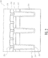
- FIG. 2 shows a cross-sectional view of an apparatus 200, in accordance with the present disclosure.
- the apparatus 200 includes a doped substrate 210, episilicon layer 212 (e.g., a drift region), a body implant layer 214, an insulating layer 216 and conductive layer 218.
- doped substrate 210 and episilicon layer 212 may be n, n- or N+, with the body implant layer 214 being p or P+.
- Deep trenches including trench 220 extend from between portions of the body implant layer 214 into the doped substrate 210. For various applications, these deep trenches are formed to a shallower depth, such as by stopping in the episilicon layer 212.
- the trench 220 is lined with an insulating material 221 and further filled with conductive material 222.
- Contacts (including 230) couple the conductive layer 218 to the trenches and the body implant layer 214.
- RESURF implants may also be added for certain embodiments, extending from the body implant layer 214 to the doped substrate 210. In various embodiments, the RESURF implants are not used. With the doped substrate 210 coupled to (or being part of) the drain of a MOSFET, and the conductive layer 218 coupled to (or being part of) the source of the MOSFET, the trenches and body implant layer portions (acting as diodes), voltage at the drain is claimed and drain-source capacitance is enhanced.
- the contact 230 between the conductive layer 218 (e.g., source) and conductive trench 220 is not continuous or omitted.
- multiple contacts may be spaced across the device and separated by sections where the conductive trench is not directly connected to the conductive layer 218.
- An R-C circuit is formed in this regard, and can be implemented to mitigate voltage oscillations between the conductive layer 218 and the doped substrate 310 (e.g., between source and drain of an adjacent FET).
- an array of trenches is used to provide capacitance.
- Such an array can be implemented, for example, with trenches as shown in Figure 2 .
- Certain applications involve such an array in which p-n junctions are formed between adjacent trenches as shown in Figure 2 (e.g., between a p body region at 214 and underlying region 212/210) or otherwise, and in which some regions between adjacent trenches do not include such a p-n junction. This approach may be useful for creating increase capacitance and/or reduced junction leakage.
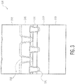
- Figure 3 shows a cross-sectional view of an apparatus 300, in accordance with the present disclosure.
- the apparatus 300 includes a doped substrate 310, episilicon layer 312, a body implant layer 314, an insulating layer 316 and conductive layer 318.
- doped substrate 310 and episilicon layer 312 may be doped N+, with the body implant layer 314 being P+. Shallow active trenches including trench 320 extend from between portions of the body implant layer 314 into the episilicon layer 312.
- Contacts including 330, which may be optionally implemented with p-body implant regions (e.g., RESURF regions) below, and couple the conductive layer 318 to the body implant layer 314.
- p-body implant regions e.g., RESURF regions
- Certain embodiments involve no RESURF structures, and some involve split-gate or stepped oxide components to provide high breakdown voltage.
- the apparatus 200 shown in Figure 2 is implemented in parallel with the apparatus 300 shown in Figure 3 , with both being connected between a source (conductive layers 218/318) and drain (doped substrates 210/310).
- each of apparatuses 200 and 300 can be coupled to common source and drain regions, with source (218/318) and drain (210/310) being shared and the respective apparatuses 200 and 300 being in parallel with one another.
- the apparatus as shown in Figure 3 can be implemented with an active area of a transistor structure, and the apparatus shown in Figure 2 can be implemented in an edge termination region of the same transistor structure.
- drift regions e.g., at 212
- desired structure e.g., p-n junction forming a diode
- various embodiments are directed to such structures as may be implemented with doping that is different than what is shown by way of example.
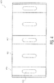
- Figure 4 shows a top view of an apparatus 400, in accordance with the present disclosure.
- the apparatus 400 may be implemented in accordance with apparatus 200 of Figure 2 , with edge termination.
- the apparatus includes trench regions including trenches 410 and 412, and body implant regions 420 therebetween.
- Contacts including contact 430 extend into each trench region and body implant region. For certain applications, contact to an underlying diode is continuous. In other applications, contact area is limited to provide a voltage clamp in areas in which the contact is not present.
- Figure 5 shows plots characterizing example trench spacing and related breakdown voltage, as may be implemented in accordance with one or more embodiments.
- the vertical axis characterizes a resulting breakdown voltage
- the horizontal axis characterizes spacing between trenches.
- Plots 510 and 520 show variation for similar doping profiles
- plots 530 and 540 show variation for doping profiles that are similar to one another but different than that of plots 510 and 520.
- orientation such as upper/lower, left/right, top/bottom and above/below, may be used herein to refer to relative positions of elements as shown in the figures. It should be understood that the terminology may be used for notational convenience only and that in actual use the disclosed structures may be oriented different from the orientation shown in the figures (for instance, structures characterized as being laterally arranged relative to one another may be stacked vertically, with similar results). Thus, the terms should not be construed in a limiting manner.
- circuits or circuitry may be illustrated as or using terms such as blocks, modules, device, system, unit, controller, clamp and/or other circuit-type depictions (e.g., reference numerals 110, 120 and 130 of Figure 1 may depict a block/module in this context).
- circuits or circuitry are discussed as being used together with other elements to exemplify how certain embodiments may be carried out in the form or structures, steps, functions, operations, activities, etc.
Landscapes
- Semiconductor Integrated Circuits (AREA)
- Metal-Oxide And Bipolar Metal-Oxide Semiconductor Integrated Circuits (AREA)
Abstract
Description
- Aspects of various embodiments are directed to circuits providing voltage clamping and capacitance, such as may be implemented for controlling high voltage devices.
- Many devices employ switching type circuits, as may be implemented in a variety of manners. For instance, high voltage switches can be desirably used with related circuitry. In some applications, a normally on device (transistor) is used with high voltages by coupling an additional device that results in net operation as being normally off. One such approach involves using a cascode arrangement with a low voltage FET (field effect transistor) coupled to a high voltage device to provide a controlling gate voltage.
- While such devices are useful, certain conditions can cause excess voltage, which can harm either or both of the high voltage device and the low voltage FET. For example, if leakage in the high voltage device is higher than that of the low voltage FET, or the low voltage FET switches off faster than the high voltage device, operation and reliability issues may arise.
- These and other matters have presented challenges to the manufacture and implementation of such devices, for a variety of applications.
- Various example embodiments are directed to issues such as those addressed above and/or others which may become apparent from the following disclosure concerning the operation of transistor circuits, such as those involving high voltage transistors. In various implementations, normally on transistors are controlled using a low-voltage transistor with enhanced capacitance and mitigation of avalanche breakdown.
- In certain example embodiments, aspects of the present disclosure involve the use of semiconductor structures that provide enhanced capacitance and avalanche breakdown control. Such aspects may be implemented with doped regions separated by trenches, which can further be formed in process steps shared with the formation of the transistors themselves.
- In accordance with a particular embodiment, an apparatus includes a cascode circuit having first and second transistors each having a gate, a source, a channel and drain, with the drain of the second transistor electrically connected to the source of the first transistor. The second transistor is operable and connected to control the first transistor in an off state by applying a voltage to the gate thereof. The apparatus also includes a plurality of conductive trenches and one or more doped regions, between adjacent ones of the conductive trenches and providing a p-n junction. The conductive trenches are configured and arranged with the doped regions to provide capacitance across the source and the drain of the second transistor, and mitigate avalanche breakdown of the second transistor by restricting voltage at one of the source and the drain of the second transistor (e.g., by clamping voltage).
- Another embodiment is directed to a method, which may be implemented with circuitry as noted above. First and second transistors are provided for a cascode circuit, each having a gate, a source, a channel and a drain, with the drain of the second transistor electrically connected to the source of the first transistor. A plurality of conductive trenches along with one or more doped regions between each adjacent trench are connected to the source and drain of the second transistor. The second transistor is utilized for controlling the first transistor in an off state by applying a voltage to the gate of the first transistor, and the conductive trenches and the doped regions are used to both provide capacitance across the source and the drain of the second transistor and mitigate avalanche breakdown of the second transistor. Avalanche breakdown can be mitigated in this context by limiting, or clamping, voltage at one of the source and the drain of the second transistor.
- In other specific example embodiments, an apparatus includes a cascode circuit, a capacitor circuit and a clamp diode circuit. The cascode circuit includes a high-voltage GaN transistor having a gate, a source, a drain and a channel that connects its source and drain. The cascode circuit also includes a low-voltage FET having a gate, a source connected to the gate of the high-voltage GaN transistor, a drain connected to the source of the high-voltage GaN transistor, and a channel that connects its source and drain. The capacitor and clamp diode circuits are connected to the source and to the drain of the low-voltage FET transistor. In certain embodiments, the low-voltage FET controls the high-voltage GaN transistor in an OFF state by applying the voltage at its source to the gate of the high-voltage GaN transistor, while the capacitor and the clamp diode provide capacitance across the source and the drain of the low-voltage FET, and mitigate avalanche breakdown of the low-voltage FET by clamping voltage across the source and the drain.
- In further specific example embodiments an apparatus comprises a transistor having a gate, a source, a channel and a drain; and a plurality of conductive trenches and at least one doped region that is between each adjacent pair of the conductive trenches and that is configured to provide a p-n junction, wherein the plurality of conductive trenches and at least one doped region are configured and arranged to provide capacitance across the source and the drain and to mitigate avalanche breakdown of the transistor by restricting a voltage level at the source or the drain.
- The drain is electrically coupled to a source of a further transistor in a cascode arrangement, and wherein said transistor is configured and arranged to control the further transistor in an off state by coupling a voltage from the source of said transistor to a gate of the cascode transistor.
- The above discussion/summary is not intended to describe each embodiment or every implementation of the present disclosure. The figures and detailed description that follow also exemplify various embodiments.
- Various example embodiments may be more completely understood in consideration of the following detailed description in connection with the accompanying drawings, in which:
-
FIG. 1 shows an apparatus in accordance with the present disclosure; -
FIG. 2 shows a cross-sectional view of an apparatus, in accordance with the present disclosure; and -
FIG. 3 shows a cross-sectional view of an apparatus, in accordance with the present disclosure; -
FIG. 4 shows a top view of an apparatus, in accordance with the present disclosure; and -
FIG. 5 shows plots characterizing example trench spacing and related breakdown voltage, as may be implemented in accordance with one or more embodiments. - While various embodiments discussed herein are amenable to modifications and alternative forms, aspects thereof have been shown by way of example in the drawings and will be described in detail. It should be understood, however, that the intention is not to limit the disclosure to the particular embodiments described. On the contrary, the intention is to cover all modifications, equivalents, and alternatives falling within the scope of the disclosure including aspects defined in the claims. In addition, the term "example" as used throughout this application is only by way of illustration, and not limitation.
- Aspects of the present disclosure are believed to be applicable to a variety of different types of apparatuses, systems and methods involving overvoltage suppression or other voltage control. In certain implementations, aspects of the present disclosure have been shown to be beneficial when used in the context of overvoltage suppression in circuits such as cascaded circuits, as may be implemented in a variety of types of circuits and related devices/systems. In some embodiments, circuitry operable with a low-voltage switch provides additional drain-source capacitance for the switch as well as clamping functions. Such circuitry may be implemented with a normally on switch or transistor (e.g., at a source of such a normally ON high-voltage switch and operable to turn the high-voltage switch off). Normally on transistors are transistors that are on (conductive) in the absence of a gate voltage. While not necessarily so limited, various aspects may be appreciated through the following discussion of non-limiting examples which use exemplary contexts.
- Accordingly, in the following description various details are set forth to describe examples presented herein. It should be apparent to one skilled in the art, however, that one or more other examples and/or variations of these examples may be practiced without all the specific details given below. In other instances, well known features have not been described in detail so as not to obscure the description of the examples herein. For ease of illustration, the same reference numerals may be used in different diagrams to refer to the same elements or additional instances of the same element. Also, although aspects and features may in some cases be described in individual figures, it will be appreciated that features from one figure or embodiment can be combined with features of another figure or embodiment even though the combination is not explicitly shown or explicitly described as a combination. For instance, the additional capacitance/clamping functions illustrated with low voltage switches may be utilized with other circuitry shown herein. Where implemented with such a low voltage switch, the additional capacitance/clamping functions (and related circuitry) can be utilized with circuitry in addition and/or as an alternative to high voltage input switches as shown in the figures, such as with implementation for a variety of different types of circuits.
- Various embodiments are directed to providing enhanced Coss (output or drain-source capacitance) and voltage clamp functions with a circuit/spacing construction that fulfils both of these roles. In various contexts, spacing between the circuitry and material (e.g., insulating) therein is set to fine tune clamping voltage. Such embodiments may be implemented with a normally ON transistor coupled to a low-voltage transistor to which the enhanced Coss is provided. For instance, a GaN (gallium nitride) normally ON transistor can be implemented with a low voltage FET (such as a MOSFET) with the enhanced Coss and voltage clamp. These approaches may be implemented, for example, to clamp the drain voltage of such a FET under conditions in which it is turning off, which can mitigate or prevent overvoltage conditions (and related avalanche) at its drain, as may otherwise be incurred as the normally ON transistor turns off rather rapidly.
- Certain embodiments are directed a structure that functions as both additional capacitance and a clamp diode, to provide enhanced Coss and voltage clamping as noted above. In connection with such embodiments, it has been recognized/discovered that a single construction can achieve these effects, and further that such construction can be carried out during processing steps for forming adjacent transistors. Consistent with various embodiments, a series of deep trenches can be constructed to provide enhanced Coss using the same process that is used for edge terminations in low voltage devices on the same die. The trenches are connected to the source of a FET as above, which provide the enhanced/additional Coss. The trenches are also used with a p-body implant between each trench (e.g., carried out with a p-body implant for main structure) to define a diode between a series of these trenches.
- In various embodiments, the breakdown voltage of such a structure is tuned to a desired value in order to provide a desired function, such as to protect the gate of a high voltage device such as a GaN device controlled by the FET and/or prevent the FET from avalanching. In one embodiment, additional implants (e.g., p or n-type) are utilized to modify the breakdown of a pn diode used as a voltage clamp. In another embodiment, the distance between the deep trenches is varied to set the breakdown voltage. In yet another embodiment, contacts with the deep trenches are defined to set the breakdown voltage, such as by providing less contact and/or contact to fewer trenches in a series of the trenches. Other embodiments employ combinations of two or more of the above, such as by adding implants and modifying deep trench distances, to tune breakdown voltage. Further approaches to setting breakdown voltage may include one or more of the following, which may also be implemented with one or more of the above: setting/changing trench depth (e.g., with capacitance being modified with trenches deeper than adjacent drift regions), varying drift region thickness, varying dopant concentration in one or more regions, and changing insulator thickness within the trenches.
- Various approaches herein may be implemented, for example, with low-voltage MOSFETs that may use RESURF (reduced surface field) principles to achieve a high breakdown voltage. For instance, the distance between the deep trenches can be increased (relative to an original design) to reduce the amount of RESURF in the structure (e.g., as shown in
Figure 4 ). Accordingly, various aspects involve circuitry and/or related systems/apparatuses that employ a voltage clamp in a cascode configuration (e.g., with a low voltage device), which utilizes a RESURF effect between two isolation trenches. This approach can be implemented to protect low voltage MOSFETs and gate of a connected switch (such as a GaN transistor) from damage due to repetitive avalanche. The voltage clamp also adds additional output capacitance which can be used to protect the device during voltage transients. - In some embodiments, a low-voltage MOSFET as characterized above is placed in the source of a high voltage device, in a cascode arrangement. The high voltage device may, for example, include a GaN HEMT (high electron mobility transistor) or an SiC JFET (silicon carbide junction gate field-effect transistor). When the low voltage MOSFET is turned off, a negative gate voltage is created in the normally on high voltage device, which turns (or maintains) it off (e.g., with the difference between the gate and the source (Vg-Vs) of the low-voltage MOSFET device being negative).
- The drain-source voltage (VDS) of the low voltage MOSFET can be characterized by the threshold voltage of the normally on high voltage device and the capacitances of the two devices, as described in the formula below:

- Various embodiments are directed to ensuring that Vx is low, or as low as possible, utilizing voltage clamping. This can help ensure that the maximum gate voltage of the normally on device is not exceeded, and can ensure that the low voltage MOSFET is not avalanched. For the latter, this can help long-term reliability. Further, this can help to ensure that the low voltage MOSFET is not avalanched in order to achieve true ZVS (zero-volt-switching) and improve efficiency in soft-switching applications. This can also help to optimize Coss-related reverse-recovery charge and minimize losses in hard switching applications. Coss can be further optimized by adding capacitance, which may also reduce Vx.
- In accordance with a particular embodiment, an apparatus includes a cascode circuit having first and second transistors each having a gate, a source, channel and drain. The drain and source of the second transistor are connected to the source and gate of the first transistor, respectively. The ON/OFF state of the second transistor can therefore be used to control the ON/OFF state of the first transistor. Moreover, the second transistor can maintain the first transistor in the OFF state in the absence of a control signal to cause the circuit to operate as a normally-off circuit.. A plurality of conductive trenches and at least one doped region between each pair of adjacent trenches, each doped region providing a p-n junction, provide capacitance across the source and the drain of the second transistor and mitigate avalanche breakdown of the second transistor by restricting a voltage level at one of the source and the drain of the second transistor. The conductive trenches may, for example, be coupled to the source of the second transistor by contacts extending from the source to the trenches. The doped regions may, for example, form part or all of a p-n diode (e.g., by forming both p and n regions of the diode, or by forming one of these regions as may interface with a different such p or n region). In some instances, the p-n junction can be formed at the intersection of the doped region and extended regions of the source and drain of the first transistor. In some implementations, the doped regions and trenches form diodes and capacitors coupled to the source and drain of the second transistor in parallel with the channel.
- Various cascode applications can be facilitated in this regard. For instance, where the first transistor is a normally ON transistor, the second transistor controls the first transistor in an OFF state by coupling a voltage from its source to the gate of the normally ON transistor. The voltage drop across the second transistor sets a negative voltage difference between the gate and source of the normally ON transistor, maintaining the OFF state.
- A variety of different types of semiconductor structures can be implemented to form the doped regions and trenches, relative to the transistor structures. In some embodiments, the doped regions and trenches may be implemented in parallel with the channel of the second transistor, with the trenches are arranged laterally adjacent one another with the doped regions laterally between the trenches. In various embodiments, the source of the second transistor includes a doped layer extending over the trenches and the doped regions, the drain of the second transistor includes a second doped layer extending below the doped regions, and the trenches extend between the doped regions and into the second doped layer. In this context, the doped regions can be formed as part of a common implant process used to form the transistors, facilitating lean processing and simplicity.
- In some embodiments, a first transistor as noted above is a high voltage transistor, and the second transistor is a low voltage transistor. High voltage in this context relates to a transistor that has a higher threshold voltage than the low voltage transistor, such as a power MOSFET, such as a GaN HEMT or a SiC JFET. This approach facilitates control with the low voltage transistor while realizing the benefits of the high voltage transistor. The second transistor switches the first transistor from an ON state to an OFF state by setting a negative gate-source voltage differential of the first transistor, while the doped regions restrict the voltage level at the drain of the second transistor relative to a clamp-voltage threshold level. This approach can facilitate switching and protection of the low-voltage transistor, such as when the timing of the switching may otherwise result in a high voltage being applied to the second transistor, via the increased capacitance and voltage clamping. For instance, the trenches and doped regions may restrict a voltage drop across the source and drain of the second transistor while the second transistor is switched from an ON state to an OFF state. As such, the second transistor can turn the first transistor off by coupling a voltage to a gate of the first transistor that provides a negative voltage difference between the gate and source of the normally ON transistor, with protection from undesirable overvoltage conditions.
- Another embodiment is directed to a method, which may be implemented with circuitry as noted above. First and second transistors are provided, each having a gate, a source, a channel and a drain, and a plurality conductive trenches with the trenches separated by one or more doped regions are provided connected to the source and drain of the second transistor. The second transistor is utilized for controlling the first transistor in an off state by applying a voltage to the gate of the first transistor, and the trenches and the doped regions are used to both provide capacitance across the source and the drain of the second transistor and mitigate avalanche breakdown of the second transistor. Avalanche breakdown can be mitigated in this context by limiting (e.g., clamping) voltage at one of the source and the drain of the second transistor.
- The doped regions and trenches can be tuned to set characteristics of operation of the second transistor. For instance, doped regions may be doped with a dopant and quantity chosen to set a breakdown voltage between the drain and channel. The trenches can be set at a distance that tunes/sets a breakdown voltage between the drain and channel. A combination of doping and channel distance can be used together to tune, or set, breakdown voltage of the second transistor.
- Turning now to the figures,
Figure 1 shows anapparatus 100 with respective switching circuitry including a first (switch)circuit 110, second (switch)circuit 120, and athird circuit 130 that operates to both clamp Vx as shown and provide additional capacitance across thesecond circuit 120. In some implementations, thefirst circuit 110 includes or is a GaN transistor, and thesecond switch 120 includes or is an NMOS transistor. As also shown by way of further example, thethird circuit 130 may include acapacitive circuity 131 anddiode circuit 132. - The
apparatus 100 can be operated in a variety of manners. In some embodiments thesecond circuit 120 is an NMOS transistor coupled to the source of the first circuit 110 (as a GaN transistor), and operates to provide control of the gate of thefirst circuit 110, as coupled atnode 121. Thesecond circuit 120 is responsive to a control signal Vg and the cascode configuration ensures that thefirst circuit 110 is OFF when Vg is not being actively driven.Capacitive circuitry 131 anddiode 132 operate to respectively enhance capacitance acrossdrain 122 andsource 123 of the NMOS transistor, and to clamp Vx, while the NMOS transistor switches to an off state and therein switches the GaN transistor off. In some embodiments, thecapacitive circuitry 131 anddiode circuit 132 are implemented between two isolation trenches, protecting the NMOS transistor from damage due to repetitive avalanche, and the voltage clamping effect further adds output capacitance that protects during voltage transients. The trenches create additional Coss and the diode effects the clamping to prevent the MOSFET from avalanching. Thecapacitive circuitry 131 anddiode circuit 132 may be connected to the drain and the source of the MOSFET in parallel with the active area of the MOSFET. - Accordingly, with the
first circuit 110 implemented as a GaN transistor andsecond circuit 120 as an NMOS transistor, the threshold voltage of the GaN transistor is negative when GaN device is off, and the difference between the gate and the source (Vg-Vs) of the GaN transistor is negative. The voltage of the source of the GaN device (VsGAN) that is connected to the drain of theMOSFET 120 is a positive value, and the voltage of the gate of the GaN device (VgGaN) that is connected to the source of the MOSFET is some value (e.g., 0) lower than the drain voltage of the MOSFET. The voltage difference between the gate and source (VgGaN-VsGaN) of the GaN device is thus negative. - The respective circuit components shown in
Figure 1 may be connected and implemented in a variety of manners. In some embodiments, thedrain 122 is connected by a bond wire to the source ofGaN transistor 110, and thesource 123 is connected by another bond wire to the gate ofGaN transistor 110. Clip bonding can be similarly used to make these connections. In other embodiments,GaN transistor 110 andNMOS transistor 120 are implemented in a common substrate/chip, along withthird circuit 130, with metal layer connections therein. - Various embodiments are directed to
circuit 130 in which thecapacitive circuitry 131 anddiode circuit 132 are part of a single structure that provides both functions. Such a circuit can be coupled to a variety of other types of circuits or devices, and functions accordingly. Other embodiments are directed tocircuit 130 as implemented withcircuit 120, with thecapacitive circuitry 131 anddiode circuit 132 providing enhanced capacitance and voltage limiting/clamping for the (transistor)circuit 120. Thecircuit 120 can then be implemented with a variety of different types of circuits, utilizing thecircuit 130 for capacitive and clamping control. -
Figure 2 shows a cross-sectional view of anapparatus 200, in accordance with the present disclosure. Theapparatus 200 includes a dopedsubstrate 210, episilicon layer 212 (e.g., a drift region), abody implant layer 214, an insulatinglayer 216 andconductive layer 218. For instance, dopedsubstrate 210 andepisilicon layer 212 may be n, n- or N+, with thebody implant layer 214 being p or P+. Deeptrenches including trench 220 extend from between portions of thebody implant layer 214 into the dopedsubstrate 210. For various applications, these deep trenches are formed to a shallower depth, such as by stopping in theepisilicon layer 212. Thetrench 220 is lined with an insulatingmaterial 221 and further filled withconductive material 222. Contacts (including 230) couple theconductive layer 218 to the trenches and thebody implant layer 214. RESURF implants may also be added for certain embodiments, extending from thebody implant layer 214 to the dopedsubstrate 210. In various embodiments, the RESURF implants are not used. With the dopedsubstrate 210 coupled to (or being part of) the drain of a MOSFET, and theconductive layer 218 coupled to (or being part of) the source of the MOSFET, the trenches and body implant layer portions (acting as diodes), voltage at the drain is claimed and drain-source capacitance is enhanced. - In some embodiments, the
contact 230 between the conductive layer 218 (e.g., source) andconductive trench 220 is not continuous or omitted. For instance, multiple contacts may be spaced across the device and separated by sections where the conductive trench is not directly connected to theconductive layer 218. An R-C circuit is formed in this regard, and can be implemented to mitigate voltage oscillations between theconductive layer 218 and the doped substrate 310 (e.g., between source and drain of an adjacent FET). - In various embodiments, an array of trenches is used to provide capacitance. Such an array can be implemented, for example, with trenches as shown in
Figure 2 . Certain applications involve such an array in which p-n junctions are formed between adjacent trenches as shown inFigure 2 (e.g., between a p body region at 214 andunderlying region 212/210) or otherwise, and in which some regions between adjacent trenches do not include such a p-n junction. This approach may be useful for creating increase capacitance and/or reduced junction leakage. -
Figure 3 shows a cross-sectional view of anapparatus 300, in accordance with the present disclosure. Various aspects ofFigure 3 can be implemented with the apparatus ofFigure 2 , with certain portions labeled similarly in this context. Theapparatus 300 includes a dopedsubstrate 310,episilicon layer 312, abody implant layer 314, an insulatinglayer 316 andconductive layer 318. Similar toFigure 2 , dopedsubstrate 310 andepisilicon layer 312 may be doped N+, with thebody implant layer 314 being P+. Shallow activetrenches including trench 320 extend from between portions of thebody implant layer 314 into theepisilicon layer 312. Contacts (including 330), which may be optionally implemented with p-body implant regions (e.g., RESURF regions) below, and couple theconductive layer 318 to thebody implant layer 314. Certain embodiments involve no RESURF structures, and some involve split-gate or stepped oxide components to provide high breakdown voltage. - In one or more embodiments, the
apparatus 200 shown inFigure 2 is implemented in parallel with theapparatus 300 shown inFigure 3 , with both being connected between a source (conductive layers 218/318) and drain (dopedsubstrates 210/310). In this context, each ofapparatuses respective apparatuses Figure 3 can be implemented with an active area of a transistor structure, and the apparatus shown inFigure 2 can be implemented in an edge termination region of the same transistor structure. - In the cross-sectional views herein, certain doped regions are shown and characterized with respective dopant types. However, it should be understood that various regions, such as drift regions (e.g., at 212), can be doped with different polarities while achieving a desired structure (e.g., p-n junction forming a diode). Accordingly, various embodiments are directed to such structures as may be implemented with doping that is different than what is shown by way of example.
-
Figure 4 shows a top view of anapparatus 400, in accordance with the present disclosure. Theapparatus 400 may be implemented in accordance withapparatus 200 ofFigure 2 , with edge termination. The apparatus includes trenchregions including trenches body implant regions 420 therebetween.Contacts including contact 430 extend into each trench region and body implant region. For certain applications, contact to an underlying diode is continuous. In other applications, contact area is limited to provide a voltage clamp in areas in which the contact is not present. -
Figure 5 shows plots characterizing example trench spacing and related breakdown voltage, as may be implemented in accordance with one or more embodiments. The vertical axis characterizes a resulting breakdown voltage, and the horizontal axis characterizes spacing between trenches.Plots plots - Terms to exemplify orientation, such as upper/lower, left/right, top/bottom and above/below, may be used herein to refer to relative positions of elements as shown in the figures. It should be understood that the terminology may be used for notational convenience only and that in actual use the disclosed structures may be oriented different from the orientation shown in the figures (for instance, structures characterized as being laterally arranged relative to one another may be stacked vertically, with similar results). Thus, the terms should not be construed in a limiting manner.
- The skilled artisan would recognize that various terminology as used in the Specification (including claims) connote a plain meaning in the art unless otherwise indicated. As examples, the specification describes and/or illustrates aspects useful for implementing the claimed disclosure by way of various circuits or circuitry. These circuits or circuitry may be illustrated as or using terms such as blocks, modules, device, system, unit, controller, clamp and/or other circuit-type depictions (e.g.,
reference numerals Figure 1 may depict a block/module in this context). Such circuits or circuitry are discussed as being used together with other elements to exemplify how certain embodiments may be carried out in the form or structures, steps, functions, operations, activities, etc. As another example, where the Specification may make reference to a "first [type of structure]", a "second [type of structure]", etc., where the [type of structure] might be replaced with terms such as ["circuit", "circuitry" and others], the adjectives "first" and "second" are not used to connote any description of the structure or to provide any substantive meaning; rather, such adjectives are merely used for English-language antecedence to differentiate one such similarly-named structure from another similarly-named structure (e.g., "first circuit configured to clamp ..." is interpreted as "circuit configured to clamp ..."). - Based upon the above discussion and illustrations, those skilled in the art will readily recognize that various modifications and changes may be made to the various embodiments without strictly following the exemplary embodiments and applications illustrated and described herein. For example, methods as exemplified in the Figures may involve steps carried out in various orders, with one or more aspects of the embodiments herein retained, or may involve fewer or more steps. The respective trenches and layers as shown may be formed in different orders or with different arrangements to achieve a particular effect. As another example, different types of high voltage devices can be utilized with low voltage switches and related componentry that effects both clamping and capacitance enhancement. Such modifications do not depart from the true spirit and scope of various aspects of the disclosure, including aspects set forth in the claims.
Claims (15)
- An apparatus comprising:a cascode circuit susceptible to overvoltage conditions including avalanche breakdown, the cascode circuit including
a first transistor having a gate, a source, a channel and a drain, and
a second transistor having a gate, a source, a channel and a drain electrically connected to the source of the first transistor, the second transistor being configured and arranged to control the first transistor in an off state by applying a voltage to the gate of the first transistor;a plurality of conductive trenches; anda set of one or more doped regions, each doped region being between a respective adjacent pair of the conductive trenches and configured to provide a p-n junction, wherein the plurality of conductive trenches and one or more doped regions are configured and arranged with the cascode circuit to provide capacitance across the source and the drain of the second transistor and to mitigate avalanche breakdown of the second transistor by restricting a voltage level at the source or the drain of the second transistor. - The apparatus of claim 1, wherein
the doped regions and trenches are part of a circuit connected to the source and drain of the second transistor in parallel with the channel of the second transistor, and the conductive trenches are arranged laterally adjacent one another with the doped regions laterally between trenches;
the source of the second transistor includes a first doped layer extending over the conductive trenches and the doped regions;
the drain of the second transistor includes a second doped layer extending below the doped regions; and
the conductive trenches extend between the doped regions and into the second doped layer. - The apparatus of claims 1 or 2, wherein:the first transistor is a high voltage transistor having a high breakdown voltage, andthe second transistor is a low voltage transistor having a low breakdown voltage that is lower than the high breakdown voltage, the second transistor having its drain coupled to the source of the first transistor, the second transistor being configured and arranged to switch the first transistor from an ON state to an OFF state by setting a negative gate-source voltage differential of the first transistor while the doped regions restrict the voltage level at the drain of the second transistor relative to a clamp-voltage threshold level.
- The apparatus of claims 1 or 2, wherein the conductive trenches are coupled to the source of the second transistor by contacts extending from the source of the second transistor to the conductive trenches.
- The apparatus of claims 1 to 4, wherein:the first transistor is a normally ON transistor, andthe second transistor is configured and arranged to control the first transistor in an OFF state by coupling a voltage from its source to the gate of the normally ON transistor that provides a negative voltage difference between the gate and source of the normally ON transistor.
- The apparatus of claims 1 to 5, wherein each doped region is part of a p-n diode including the doped region and extended regions of the source and drain of the first transistor, each p-n diode having a portion thereof separated by one of the conductive trenches.
- The apparatus of claims 1 to 6, wherein the conductive trenches and doped regions are configured and arranged to restrict a voltage drop across the source and drain of the second transistor while the second transistor is switched from an ON state to an OFF state and while the second transistor turns the first transistor off by coupling a voltage to a gate of the first transistor that provides a negative voltage difference between the gate and source of the first transistor.
- The apparatus of claims 1 to 7, wherein
the first transistor is a normally-on circuit, and
the second transistor is configured and arranged to operate the normally-on circuit in a normally-off state. - The apparatus of claims 1 to 7, wherein the doped regions and trenches form diodes and capacitors that are connected in parallel between the source and drain of the second transistor, and/or wherein the doped regions are configured and arranged with dopants therein to set a breakdown voltage between the drain and channel, and/or wherein the conductive trenches are configured and arranged at a distance therebetween to set a breakdown voltage between the drain and channel, and/or wherein the conductive trenches and doped regions are configured and arranged to set a breakdown voltage between the drain and channel via dopants in the doped regions and a distance at which the conductive trenches are spaced.
- A method comprising:providing a transistor having a gate, a source, a channel and a drain, the transistor being susceptible to overvoltage conditions including avalanche breakdown;providing a plurality of conductive trenches;providing at least one doped region between an adjacent pair of the conductive trenches, each doped region providing a p-n junction; andutilizing the conductive trenches and the doped regions to provide capacitance across the source and the drain, and to mitigate avalanche breakdown of the transistor by restricting a voltage level at one of the source and the drain.
- The method of claim 10, wherein the steps of providing the transistor, providing the plurality of conductive trenches and providing the at least one doped region include concurrently forming a portion of the transistor and a portion of the plurality of conductive trenches and the at least one doped region in a common process.
- The method of claims 10 or 11, further including:electrically coupling the drain to a source of a cascode transistor; andcontrolling the cascode transistor in an off state by coupling a voltage to a gate of the cascode transistor.
- The method of claims 10 to 12, further including setting a breakdown voltage between the drain and channel by one or more of:doping the at least one doped region to achieve the breakdown voltage;providing the at least one doped region separated by the conductive trenches at a fixed distance that sets the breakdown voltage;setting a depth of the conductive trenches;setting a thickness of an insulation layer, and forming the conductive trenches by lining each trench with the insulation layer at the set thickness.
- The method of claims 10 to 13, wherein
providing the at least one doped region includes forming diodes with the plurality of doped regions, the diodes being connected between the source and the drain of the second transistor, and
restricting the voltage level at one of the source and the drain of the second transistor includes using the diodes to clamp the voltage. - The method of claims 10 to 14, wherein providing the plurality of conductive trenches includes electrically connecting at least one of the trenches to the source and forming an R-C circuit by electrically separating at least another one of the trenches from the source, the R-C circuit being configured to reduce voltage oscillations across the source and drain.
Applications Claiming Priority (1)
| Application Number | Priority Date | Filing Date | Title |
|---|---|---|---|
| US15/200,308 US9941265B2 (en) | 2016-07-01 | 2016-07-01 | Circuitry with voltage limiting and capactive enhancement |
Publications (2)
| Publication Number | Publication Date |
|---|---|
| EP3264463A1 true EP3264463A1 (en) | 2018-01-03 |
| EP3264463B1 EP3264463B1 (en) | 2022-07-27 |
Family
ID=58714952
Family Applications (1)
| Application Number | Title | Priority Date | Filing Date |
|---|---|---|---|
| EP17171149.2A Active EP3264463B1 (en) | 2016-07-01 | 2017-05-15 | Circuitry with voltage limiting and capactive enhancement |
Country Status (3)
| Country | Link |
|---|---|
| US (1) | US9941265B2 (en) |
| EP (1) | EP3264463B1 (en) |
| CN (1) | CN107564903B (en) |
Cited By (2)
| Publication number | Priority date | Publication date | Assignee | Title |
|---|---|---|---|---|
| EP3664136A1 (en) * | 2018-12-06 | 2020-06-10 | Nexperia B.V. | Semiconductor device with integrated clamp diode |
| TWI905931B (en) * | 2023-10-10 | 2025-11-21 | 香港科技大學 | Cascode semiconductor devicess, circuits, and methods of operating the same |
Families Citing this family (6)
| Publication number | Priority date | Publication date | Assignee | Title |
|---|---|---|---|---|
| CN111490663B (en) * | 2019-01-25 | 2021-02-02 | 苏州捷芯威半导体有限公司 | Intelligent integrated switch tube and resonant soft switch circuit |
| US11632054B2 (en) | 2019-04-24 | 2023-04-18 | Power Integrations, Inc. | Mode operation detection for control of a power converter with an active clamp switch |
| WO2020219116A1 (en) | 2019-04-24 | 2020-10-29 | Power Integrations, Inc. | Power converter comprising an active non-dissipative clamp circuit, and respective controller |
| US10965218B1 (en) * | 2019-11-15 | 2021-03-30 | Power Integrations, Inc. | Active clamp circuit with steering network |
| CN111430347B (en) * | 2020-06-11 | 2020-09-04 | 嘉兴景焱智能装备技术有限公司 | Gallium nitride gate cascade cell and its integrated semiconductor structure |
| US20240056035A1 (en) * | 2022-08-12 | 2024-02-15 | Skyworks Solutions, Inc. | Apparatus and methods for amplifier linearization |
Citations (5)
| Publication number | Priority date | Publication date | Assignee | Title |
|---|---|---|---|---|
| WO2008063592A2 (en) * | 2006-11-16 | 2008-05-29 | Alpha & Omega Semiconductor, Ltd. | Circuit configuration and manufacturing processes for vertical transient voltage suppressor (tvs) and emi filter |
| EP2256799A2 (en) * | 2009-05-28 | 2010-12-01 | International Rectifier Corporation | Monolithic vertically integrated composite group III-V and group IV semiconductor device and method for fabricating same |
| US20110210338A1 (en) * | 2010-03-01 | 2011-09-01 | International Rectifier Corporation | Efficient High Voltage Switching Circuits and Monolithic Integration of Same |
| EP2546883A2 (en) * | 2011-07-15 | 2013-01-16 | International Rectifier Corporation | Composite Semiconductor Device with a SOI Substrate Having an Integrated Diode |
| EP2736073A1 (en) * | 2012-11-21 | 2014-05-28 | Nxp B.V. | Cascode semiconductor device |
Family Cites Families (6)
| Publication number | Priority date | Publication date | Assignee | Title |
|---|---|---|---|---|
| US7291884B2 (en) * | 2001-07-03 | 2007-11-06 | Siliconix Incorporated | Trench MIS device having implanted drain-drift region and thick bottom oxide |
| US8304314B2 (en) * | 2008-09-24 | 2012-11-06 | Semiconductor Components Industries, Llc | Method of forming an MOS transistor |
| US9859882B2 (en) | 2011-03-21 | 2018-01-02 | Infineon Technologies Americas Corp. | High voltage composite semiconductor device with protection for a low voltage device |
| US9171837B2 (en) | 2012-12-17 | 2015-10-27 | Nxp B.V. | Cascode circuit |
| EP2784816A1 (en) * | 2013-03-28 | 2014-10-01 | Nxp B.V. | Cascode semiconductor device |
| US9620637B2 (en) * | 2013-05-24 | 2017-04-11 | Infineon Technologies Ag | Semiconductor device comprising a gate electrode connected to a source terminal |
-
2016
- 2016-07-01 US US15/200,308 patent/US9941265B2/en active Active
-
2017
- 2017-05-15 EP EP17171149.2A patent/EP3264463B1/en active Active
- 2017-06-30 CN CN201710522574.9A patent/CN107564903B/en active Active
Patent Citations (5)
| Publication number | Priority date | Publication date | Assignee | Title |
|---|---|---|---|---|
| WO2008063592A2 (en) * | 2006-11-16 | 2008-05-29 | Alpha & Omega Semiconductor, Ltd. | Circuit configuration and manufacturing processes for vertical transient voltage suppressor (tvs) and emi filter |
| EP2256799A2 (en) * | 2009-05-28 | 2010-12-01 | International Rectifier Corporation | Monolithic vertically integrated composite group III-V and group IV semiconductor device and method for fabricating same |
| US20110210338A1 (en) * | 2010-03-01 | 2011-09-01 | International Rectifier Corporation | Efficient High Voltage Switching Circuits and Monolithic Integration of Same |
| EP2546883A2 (en) * | 2011-07-15 | 2013-01-16 | International Rectifier Corporation | Composite Semiconductor Device with a SOI Substrate Having an Integrated Diode |
| EP2736073A1 (en) * | 2012-11-21 | 2014-05-28 | Nxp B.V. | Cascode semiconductor device |
Cited By (3)
| Publication number | Priority date | Publication date | Assignee | Title |
|---|---|---|---|---|
| EP3664136A1 (en) * | 2018-12-06 | 2020-06-10 | Nexperia B.V. | Semiconductor device with integrated clamp diode |
| US11088273B2 (en) | 2018-12-06 | 2021-08-10 | Nexperia B.V. | Semiconductor device with integrated clamp diode |
| TWI905931B (en) * | 2023-10-10 | 2025-11-21 | 香港科技大學 | Cascode semiconductor devicess, circuits, and methods of operating the same |
Also Published As
| Publication number | Publication date |
|---|---|
| US20180006015A1 (en) | 2018-01-04 |
| CN107564903A (en) | 2018-01-09 |
| EP3264463B1 (en) | 2022-07-27 |
| CN107564903B (en) | 2023-05-26 |
| US9941265B2 (en) | 2018-04-10 |
Similar Documents
| Publication | Publication Date | Title |
|---|---|---|
| EP3264463B1 (en) | Circuitry with voltage limiting and capactive enhancement | |
| US9768160B2 (en) | Semiconductor device, electronic circuit and method for switching high voltages | |
| US8546875B1 (en) | Vertical transistor having edge termination structure | |
| US8823081B2 (en) | Transistor device with field electrode | |
| JP5520215B2 (en) | Improved power switching transistor | |
| US8803205B2 (en) | Transistor with controllable compensation regions | |
| KR102248307B1 (en) | Power integrated device, and electronic device and electronic system having the power integrated device | |
| US9825129B2 (en) | Transistor device | |
| US10121907B2 (en) | Planar triple-implanted JFET | |
| US20170194485A1 (en) | Split-gate superjunction power transistor | |
| US11133391B2 (en) | Transistor device | |
| EP3571722B1 (en) | Vertical fet structure | |
| US10355132B2 (en) | Power MOSFETs with superior high frequency figure-of-merit | |
| CN106887451B (en) | Super junction device and manufacturing method thereof | |
| EP3361511A1 (en) | Laterally diffused metal-oxide semiconductor field-effect transistor | |
| US20200105742A1 (en) | A semiconductor device comprising an insulated gate field transistor connected on series with a high voltage field effect transistor | |
| Jiang et al. | Simulation study of 4h-SiC trench MOSFETs with various gate structures | |
| US10991812B2 (en) | Transistor device with a rectifier element between a field electrode and a source electrode | |
| CN106876461A (en) | The manufacture method of semiconductor devices and semiconductor devices | |
| CN116031303B (en) | Super junction device, manufacturing method thereof and electronic device | |
| CN107579109A (en) | Semiconductor device and manufacturing method thereof | |
| Vashchenko et al. | On chip ESD protection of 600V voltage node |
Legal Events
| Date | Code | Title | Description |
|---|---|---|---|
| PUAI | Public reference made under article 153(3) epc to a published international application that has entered the european phase |
Free format text: ORIGINAL CODE: 0009012 |
|
| STAA | Information on the status of an ep patent application or granted ep patent |
Free format text: STATUS: THE APPLICATION HAS BEEN PUBLISHED |
|
| AK | Designated contracting states |
Kind code of ref document: A1 Designated state(s): AL AT BE BG CH CY CZ DE DK EE ES FI FR GB GR HR HU IE IS IT LI LT LU LV MC MK MT NL NO PL PT RO RS SE SI SK SM TR |
|
| AX | Request for extension of the european patent |
Extension state: BA ME |
|
| RBV | Designated contracting states (corrected) |
Designated state(s): AL AT BE BG CH CY CZ DE DK EE ES FI FR GB GR HR HU IE IS IT LI LT LU LV MC MK MT NL NO PL PT RO RS SE SI SK SM TR |
|
| STAA | Information on the status of an ep patent application or granted ep patent |
Free format text: STATUS: REQUEST FOR EXAMINATION WAS MADE |
|
| 17P | Request for examination filed |
Effective date: 20180928 |
|
| STAA | Information on the status of an ep patent application or granted ep patent |
Free format text: STATUS: EXAMINATION IS IN PROGRESS |
|
| 17Q | First examination report despatched |
Effective date: 20200504 |
|
| GRAP | Despatch of communication of intention to grant a patent |
Free format text: ORIGINAL CODE: EPIDOSNIGR1 |
|
| STAA | Information on the status of an ep patent application or granted ep patent |
Free format text: STATUS: GRANT OF PATENT IS INTENDED |
|
| RIC1 | Information provided on ipc code assigned before grant |
Ipc: H01L 29/16 20060101ALI20220211BHEP Ipc: H01L 27/07 20060101ALI20220211BHEP Ipc: H01L 29/417 20060101ALI20220211BHEP Ipc: H01L 29/78 20060101ALI20220211BHEP Ipc: H01L 29/20 20060101ALI20220211BHEP Ipc: H01L 29/06 20060101ALI20220211BHEP Ipc: H01L 27/02 20060101AFI20220211BHEP |
|
| INTG | Intention to grant announced |
Effective date: 20220309 |
|
| GRAS | Grant fee paid |
Free format text: ORIGINAL CODE: EPIDOSNIGR3 |
|
| GRAJ | Information related to disapproval of communication of intention to grant by the applicant or resumption of examination proceedings by the epo deleted |
Free format text: ORIGINAL CODE: EPIDOSDIGR1 |
|
| STAA | Information on the status of an ep patent application or granted ep patent |
Free format text: STATUS: EXAMINATION IS IN PROGRESS |
|
| GRAS | Grant fee paid |
Free format text: ORIGINAL CODE: EPIDOSNIGR3 |
|
| STAA | Information on the status of an ep patent application or granted ep patent |
Free format text: STATUS: GRANT OF PATENT IS INTENDED |
|
| INTC | Intention to grant announced (deleted) | ||
| GRAP | Despatch of communication of intention to grant a patent |
Free format text: ORIGINAL CODE: EPIDOSNIGR1 |
|
| GRAF | Information related to payment of grant fee modified |
Free format text: ORIGINAL CODE: EPIDOSCIGR3 |
|
| GRAA | (expected) grant |
Free format text: ORIGINAL CODE: 0009210 |
|
| STAA | Information on the status of an ep patent application or granted ep patent |
Free format text: STATUS: THE PATENT HAS BEEN GRANTED |
|
| INTG | Intention to grant announced |
Effective date: 20220621 |
|
| AK | Designated contracting states |
Kind code of ref document: B1 Designated state(s): AL AT BE BG CH CY CZ DE DK EE ES FI FR GB GR HR HU IE IS IT LI LT LU LV MC MK MT NL NO PL PT RO RS SE SI SK SM TR |
|
| REG | Reference to a national code |
Ref country code: CH Ref legal event code: EP |
|
| REG | Reference to a national code |
Ref country code: DE Ref legal event code: R096 Ref document number: 602017059811 Country of ref document: DE |
|
| REG | Reference to a national code |
Ref country code: AT Ref legal event code: REF Ref document number: 1507646 Country of ref document: AT Kind code of ref document: T Effective date: 20220815 |
|
| REG | Reference to a national code |
Ref country code: IE Ref legal event code: FG4D |
|
| REG | Reference to a national code |
Ref country code: LT Ref legal event code: MG9D |
|
| REG | Reference to a national code |
Ref country code: NL Ref legal event code: MP Effective date: 20220727 |
|
| PG25 | Lapsed in a contracting state [announced via postgrant information from national office to epo] |
Ref country code: SE Free format text: LAPSE BECAUSE OF FAILURE TO SUBMIT A TRANSLATION OF THE DESCRIPTION OR TO PAY THE FEE WITHIN THE PRESCRIBED TIME-LIMIT Effective date: 20220727 Ref country code: RS Free format text: LAPSE BECAUSE OF FAILURE TO SUBMIT A TRANSLATION OF THE DESCRIPTION OR TO PAY THE FEE WITHIN THE PRESCRIBED TIME-LIMIT Effective date: 20220727 Ref country code: PT Free format text: LAPSE BECAUSE OF FAILURE TO SUBMIT A TRANSLATION OF THE DESCRIPTION OR TO PAY THE FEE WITHIN THE PRESCRIBED TIME-LIMIT Effective date: 20221128 Ref country code: NO Free format text: LAPSE BECAUSE OF FAILURE TO SUBMIT A TRANSLATION OF THE DESCRIPTION OR TO PAY THE FEE WITHIN THE PRESCRIBED TIME-LIMIT Effective date: 20221027 Ref country code: NL Free format text: LAPSE BECAUSE OF FAILURE TO SUBMIT A TRANSLATION OF THE DESCRIPTION OR TO PAY THE FEE WITHIN THE PRESCRIBED TIME-LIMIT Effective date: 20220727 Ref country code: LV Free format text: LAPSE BECAUSE OF FAILURE TO SUBMIT A TRANSLATION OF THE DESCRIPTION OR TO PAY THE FEE WITHIN THE PRESCRIBED TIME-LIMIT Effective date: 20220727 Ref country code: LT Free format text: LAPSE BECAUSE OF FAILURE TO SUBMIT A TRANSLATION OF THE DESCRIPTION OR TO PAY THE FEE WITHIN THE PRESCRIBED TIME-LIMIT Effective date: 20220727 Ref country code: FI Free format text: LAPSE BECAUSE OF FAILURE TO SUBMIT A TRANSLATION OF THE DESCRIPTION OR TO PAY THE FEE WITHIN THE PRESCRIBED TIME-LIMIT Effective date: 20220727 Ref country code: ES Free format text: LAPSE BECAUSE OF FAILURE TO SUBMIT A TRANSLATION OF THE DESCRIPTION OR TO PAY THE FEE WITHIN THE PRESCRIBED TIME-LIMIT Effective date: 20220727 |
|
| REG | Reference to a national code |
Ref country code: AT Ref legal event code: MK05 Ref document number: 1507646 Country of ref document: AT Kind code of ref document: T Effective date: 20220727 |
|
| PG25 | Lapsed in a contracting state [announced via postgrant information from national office to epo] |
Ref country code: PL Free format text: LAPSE BECAUSE OF FAILURE TO SUBMIT A TRANSLATION OF THE DESCRIPTION OR TO PAY THE FEE WITHIN THE PRESCRIBED TIME-LIMIT Effective date: 20220727 Ref country code: IS Free format text: LAPSE BECAUSE OF FAILURE TO SUBMIT A TRANSLATION OF THE DESCRIPTION OR TO PAY THE FEE WITHIN THE PRESCRIBED TIME-LIMIT Effective date: 20221127 Ref country code: HR Free format text: LAPSE BECAUSE OF FAILURE TO SUBMIT A TRANSLATION OF THE DESCRIPTION OR TO PAY THE FEE WITHIN THE PRESCRIBED TIME-LIMIT Effective date: 20220727 Ref country code: GR Free format text: LAPSE BECAUSE OF FAILURE TO SUBMIT A TRANSLATION OF THE DESCRIPTION OR TO PAY THE FEE WITHIN THE PRESCRIBED TIME-LIMIT Effective date: 20221028 |
|
| PG25 | Lapsed in a contracting state [announced via postgrant information from national office to epo] |
Ref country code: SM Free format text: LAPSE BECAUSE OF FAILURE TO SUBMIT A TRANSLATION OF THE DESCRIPTION OR TO PAY THE FEE WITHIN THE PRESCRIBED TIME-LIMIT Effective date: 20220727 Ref country code: RO Free format text: LAPSE BECAUSE OF FAILURE TO SUBMIT A TRANSLATION OF THE DESCRIPTION OR TO PAY THE FEE WITHIN THE PRESCRIBED TIME-LIMIT Effective date: 20220727 Ref country code: DK Free format text: LAPSE BECAUSE OF FAILURE TO SUBMIT A TRANSLATION OF THE DESCRIPTION OR TO PAY THE FEE WITHIN THE PRESCRIBED TIME-LIMIT Effective date: 20220727 Ref country code: CZ Free format text: LAPSE BECAUSE OF FAILURE TO SUBMIT A TRANSLATION OF THE DESCRIPTION OR TO PAY THE FEE WITHIN THE PRESCRIBED TIME-LIMIT Effective date: 20220727 Ref country code: AT Free format text: LAPSE BECAUSE OF FAILURE TO SUBMIT A TRANSLATION OF THE DESCRIPTION OR TO PAY THE FEE WITHIN THE PRESCRIBED TIME-LIMIT Effective date: 20220727 |
|
| REG | Reference to a national code |
Ref country code: DE Ref legal event code: R097 Ref document number: 602017059811 Country of ref document: DE |
|
| PG25 | Lapsed in a contracting state [announced via postgrant information from national office to epo] |
Ref country code: SK Free format text: LAPSE BECAUSE OF FAILURE TO SUBMIT A TRANSLATION OF THE DESCRIPTION OR TO PAY THE FEE WITHIN THE PRESCRIBED TIME-LIMIT Effective date: 20220727 Ref country code: EE Free format text: LAPSE BECAUSE OF FAILURE TO SUBMIT A TRANSLATION OF THE DESCRIPTION OR TO PAY THE FEE WITHIN THE PRESCRIBED TIME-LIMIT Effective date: 20220727 |
|
| PLBE | No opposition filed within time limit |
Free format text: ORIGINAL CODE: 0009261 |
|
| STAA | Information on the status of an ep patent application or granted ep patent |
Free format text: STATUS: NO OPPOSITION FILED WITHIN TIME LIMIT |
|
| PG25 | Lapsed in a contracting state [announced via postgrant information from national office to epo] |
Ref country code: AL Free format text: LAPSE BECAUSE OF FAILURE TO SUBMIT A TRANSLATION OF THE DESCRIPTION OR TO PAY THE FEE WITHIN THE PRESCRIBED TIME-LIMIT Effective date: 20220727 |
|
| 26N | No opposition filed |
Effective date: 20230502 |
|
| PG25 | Lapsed in a contracting state [announced via postgrant information from national office to epo] |
Ref country code: SI Free format text: LAPSE BECAUSE OF FAILURE TO SUBMIT A TRANSLATION OF THE DESCRIPTION OR TO PAY THE FEE WITHIN THE PRESCRIBED TIME-LIMIT Effective date: 20220727 |
|
| REG | Reference to a national code |
Ref country code: CH Ref legal event code: PL |
|
| PG25 | Lapsed in a contracting state [announced via postgrant information from national office to epo] |
Ref country code: MC Free format text: LAPSE BECAUSE OF FAILURE TO SUBMIT A TRANSLATION OF THE DESCRIPTION OR TO PAY THE FEE WITHIN THE PRESCRIBED TIME-LIMIT Effective date: 20220727 |
|
| GBPC | Gb: european patent ceased through non-payment of renewal fee |
Effective date: 20230515 |
|
| REG | Reference to a national code |
Ref country code: BE Ref legal event code: MM Effective date: 20230531 |
|
| PG25 | Lapsed in a contracting state [announced via postgrant information from national office to epo] |
Ref country code: MC Free format text: LAPSE BECAUSE OF FAILURE TO SUBMIT A TRANSLATION OF THE DESCRIPTION OR TO PAY THE FEE WITHIN THE PRESCRIBED TIME-LIMIT Effective date: 20220727 Ref country code: LU Free format text: LAPSE BECAUSE OF NON-PAYMENT OF DUE FEES Effective date: 20230515 Ref country code: LI Free format text: LAPSE BECAUSE OF NON-PAYMENT OF DUE FEES Effective date: 20230531 Ref country code: CH Free format text: LAPSE BECAUSE OF NON-PAYMENT OF DUE FEES Effective date: 20230531 |
|
| REG | Reference to a national code |
Ref country code: IE Ref legal event code: MM4A |
|
| PG25 | Lapsed in a contracting state [announced via postgrant information from national office to epo] |
Ref country code: IE Free format text: LAPSE BECAUSE OF NON-PAYMENT OF DUE FEES Effective date: 20230515 |
|
| PG25 | Lapsed in a contracting state [announced via postgrant information from national office to epo] |
Ref country code: IE Free format text: LAPSE BECAUSE OF NON-PAYMENT OF DUE FEES Effective date: 20230515 Ref country code: GB Free format text: LAPSE BECAUSE OF NON-PAYMENT OF DUE FEES Effective date: 20230515 |
|
| PG25 | Lapsed in a contracting state [announced via postgrant information from national office to epo] |
Ref country code: IT Free format text: LAPSE BECAUSE OF FAILURE TO SUBMIT A TRANSLATION OF THE DESCRIPTION OR TO PAY THE FEE WITHIN THE PRESCRIBED TIME-LIMIT Effective date: 20220727 Ref country code: FR Free format text: LAPSE BECAUSE OF NON-PAYMENT OF DUE FEES Effective date: 20230531 Ref country code: BE Free format text: LAPSE BECAUSE OF NON-PAYMENT OF DUE FEES Effective date: 20230531 |
|
| PG25 | Lapsed in a contracting state [announced via postgrant information from national office to epo] |
Ref country code: BG Free format text: LAPSE BECAUSE OF FAILURE TO SUBMIT A TRANSLATION OF THE DESCRIPTION OR TO PAY THE FEE WITHIN THE PRESCRIBED TIME-LIMIT Effective date: 20220727 |
|
| REG | Reference to a national code |
Ref country code: DE Ref legal event code: R079 Ref document number: 602017059811 Country of ref document: DE Free format text: PREVIOUS MAIN CLASS: H01L0027020000 Ipc: H10D0089000000 |
|
| PG25 | Lapsed in a contracting state [announced via postgrant information from national office to epo] |
Ref country code: BG Free format text: LAPSE BECAUSE OF FAILURE TO SUBMIT A TRANSLATION OF THE DESCRIPTION OR TO PAY THE FEE WITHIN THE PRESCRIBED TIME-LIMIT Effective date: 20220727 |
|
| PGFP | Annual fee paid to national office [announced via postgrant information from national office to epo] |
Ref country code: DE Payment date: 20250528 Year of fee payment: 9 |
|
| PG25 | Lapsed in a contracting state [announced via postgrant information from national office to epo] |
Ref country code: CY Free format text: LAPSE BECAUSE OF FAILURE TO SUBMIT A TRANSLATION OF THE DESCRIPTION OR TO PAY THE FEE WITHIN THE PRESCRIBED TIME-LIMIT; INVALID AB INITIO Effective date: 20170515 |
|
| PG25 | Lapsed in a contracting state [announced via postgrant information from national office to epo] |
Ref country code: HU Free format text: LAPSE BECAUSE OF FAILURE TO SUBMIT A TRANSLATION OF THE DESCRIPTION OR TO PAY THE FEE WITHIN THE PRESCRIBED TIME-LIMIT; INVALID AB INITIO Effective date: 20170515 |
|
| PG25 | Lapsed in a contracting state [announced via postgrant information from national office to epo] |
Ref country code: TR Free format text: LAPSE BECAUSE OF FAILURE TO SUBMIT A TRANSLATION OF THE DESCRIPTION OR TO PAY THE FEE WITHIN THE PRESCRIBED TIME-LIMIT Effective date: 20220727 |