EP3264357A1 - Systems and methods to integrate power production simulation with power distribution simulation - Google Patents
Systems and methods to integrate power production simulation with power distribution simulation Download PDFInfo
- Publication number
- EP3264357A1 EP3264357A1 EP17177321.1A EP17177321A EP3264357A1 EP 3264357 A1 EP3264357 A1 EP 3264357A1 EP 17177321 A EP17177321 A EP 17177321A EP 3264357 A1 EP3264357 A1 EP 3264357A1
- Authority
- EP
- European Patent Office
- Prior art keywords
- model
- simulation
- pdmss
- ppmss
- power
- Prior art date
- Legal status (The legal status is an assumption and is not a legal conclusion. Google has not performed a legal analysis and makes no representation as to the accuracy of the status listed.)
- Ceased
Links
Images



Classifications
-
- G—PHYSICS
- G06—COMPUTING OR CALCULATING; COUNTING
- G06F—ELECTRIC DIGITAL DATA PROCESSING
- G06F30/00—Computer-aided design [CAD]
- G06F30/20—Design optimisation, verification or simulation
-
- G—PHYSICS
- G06—COMPUTING OR CALCULATING; COUNTING
- G06F—ELECTRIC DIGITAL DATA PROCESSING
- G06F30/00—Computer-aided design [CAD]
- G06F30/30—Circuit design
- G06F30/36—Circuit design at the analogue level
- G06F30/367—Design verification, e.g. using simulation, simulation program with integrated circuit emphasis [SPICE], direct methods or relaxation methods
-
- G—PHYSICS
- G06—COMPUTING OR CALCULATING; COUNTING
- G06Q—INFORMATION AND COMMUNICATION TECHNOLOGY [ICT] SPECIALLY ADAPTED FOR ADMINISTRATIVE, COMMERCIAL, FINANCIAL, MANAGERIAL OR SUPERVISORY PURPOSES; SYSTEMS OR METHODS SPECIALLY ADAPTED FOR ADMINISTRATIVE, COMMERCIAL, FINANCIAL, MANAGERIAL OR SUPERVISORY PURPOSES, NOT OTHERWISE PROVIDED FOR
- G06Q10/00—Administration; Management
- G06Q10/04—Forecasting or optimisation specially adapted for administrative or management purposes, e.g. linear programming or "cutting stock problem"
-
- G—PHYSICS
- G06—COMPUTING OR CALCULATING; COUNTING
- G06Q—INFORMATION AND COMMUNICATION TECHNOLOGY [ICT] SPECIALLY ADAPTED FOR ADMINISTRATIVE, COMMERCIAL, FINANCIAL, MANAGERIAL OR SUPERVISORY PURPOSES; SYSTEMS OR METHODS SPECIALLY ADAPTED FOR ADMINISTRATIVE, COMMERCIAL, FINANCIAL, MANAGERIAL OR SUPERVISORY PURPOSES, NOT OTHERWISE PROVIDED FOR
- G06Q50/00—Information and communication technology [ICT] specially adapted for implementation of business processes of specific business sectors, e.g. utilities or tourism
- G06Q50/06—Energy or water supply
-
- G—PHYSICS
- G06—COMPUTING OR CALCULATING; COUNTING
- G06F—ELECTRIC DIGITAL DATA PROCESSING
- G06F2119/00—Details relating to the type or aim of the analysis or the optimisation
- G06F2119/06—Power analysis or power optimisation
Definitions
- the subject matter disclosed herein relates to power production simulation and power distribution simulation, and more specifically, the integration of power production simulation with power distribution simulation.
- Certain systems may model and simulate power production systems, such as a power production plant, and simulate the resulting power production systems, for example, to validate and verify a new power production plant design.
- certain systems may model and simulate power distribution and/or consumption, such as an electric grid and power consumptive sites electrically coupled to the grid.
- the power distribution and/or consumption models may be useful, for example, in simulating the transmission of power through a network, and/or the subsequent use of the power. It would be advantageous to integrate systems that model and simulate power productions systems with systems that model and simulate power distribution and/or consumption systems.
- a system in a first embodiment, includes a processor.
- the processor is configured to provide for time synchronization between execution of a power production modeling and simulation system (PPMSS) model and a power distribution modeling and simulation system (PDMSS) model, wherein the PPMSS model comprises a power production system simulation and wherein the PDMSS model comprises a power distribution system simulation.
- PPMSS power production modeling and simulation system
- PDMSS power distribution modeling and simulation system
- a method includes executing, via a processor, a simulation integration system configured to provide for time synchronization between execution of a power production modeling and simulation system (PPMSS) model and a power distribution modeling and simulation system (PDMSS) model, wherein the PPMSS model comprises a power production system simulation and wherein the PDMSS model comprises a power distribution system simulation.
- PPMSS power production modeling and simulation system
- PDMSS power distribution modeling and simulation system
- a tangible, non-transitory, computer-readable medium includes instructions that when executed by a processor cause the processor to execute a simulation integration system configured to provide for time synchronization between execution of a power production modeling and simulation system (PPMSS) model and a power distribution modeling and simulation system (PDMSS) model, wherein the PPMSS model comprises a power production system simulation and wherein the PDMSS model comprises a power distribution system simulation.
- a simulation integration system configured to provide for time synchronization between execution of a power production modeling and simulation system (PPMSS) model and a power distribution modeling and simulation system (PDMSS) model
- PPMSS power production modeling and simulation system
- PDMSS power distribution modeling and simulation system
- a transient model of power generation and a transient model of power distribution and/or consumption may be integrated via software without being dependent on special hardware, e.g. reflective memory (RFM), to facilitate inter-process communication and time synchronization between both models.
- the system including the power production and generation model referred to herein as the power production modeling and simulation system (PPMSS)
- PMSS power production modeling and simulation system
- PMSS power distribution modeling and simulation system
- Model execution may refer to an integration of simulation time by a prescribed or pre-configured integration time step.
- the PDMSS will read inputs, solve state and algebraic equations, and write outputs.
- the PDMSS will include a smaller time step for numerical integration as compared to the PPMSS. Accordingly, the PDMSS model will run at a higher frequency until simulation time for that execution cycle equates to an integration time step for the PPMSS model, at which time control is relinquished to PPMSS to complete another cycle.
- a frequency of data exchange is exclusively determined by the integration time step configured in each model.
- Data exchange may preferably include shared memory exchanges, but other inter process communication (IPC) techniques may also be used, including named pipes, sockets, message passing, message queues, and the like.
- IPC inter process communication
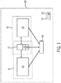
- FIG. 1 the figure illustrates an embodiment of a PPMSS 8 operatively coupled to a PDMSS 10 via a simulation integration system 12.
- the simulation integration system 12 may be included in the PPMSS 8.
- the simulation integration system 12 may be included in the PDMSS 10.
- the simulation integration system 12 may be a standalone system, or included in another system not shown.
- the simulation integration system 12 may further include a library system 14 and a dynamic link library (DLL) system 16.
- the library system 14 may provide for an application programming interface (API) suitable for interfacing between the PPMSS 8 and the PDMSS 10.
- API application programming interface
- the API may expose certain functions, subroutines, programming interfaces, system calls (e.g., operating system functions and/or subroutines), constants, and the like, useful in exchanging data between the PPMSS 8 and the PDMSS 10, as further described below.
- the DLL system 16 may include executable code or instructions that may be loaded, for example, at runtime, by the PPMSS 8 and/or the PDMSS 10 to execute the functions, subroutines, programming interfaces, system calls, constants, and the like, described via the library system 14.
- a shared memory system 18 is also illustrated.
- the PPMSS 8 and the PDMSS 10 may share data via the shared memory system 18.
- the simulation integration system 12 may mediate between the PPMSS 8 and the PDMSS 10 to update data every simulation integration time step as a simulation advances in time.
- Data included in the shared memory system 18 may be protected by system locks (mutex) to ensure data integrity.
- Time synchronization (e.g., handshaking) between models 20, 22 may be facilitated with system (e.g.., operating system) events.
- the transient model 20 executing within the PPMSS 8 is the master and the transient model 22 executing within the PDMSS 10 is the slave. That is, the transient model 20 determines when to invoke the transient model 22 for further execution.
- the transient model 22 executes at a higher frequency when compared to the transient model 20, e.g. the transient model 22 may include an integration time step of 4 ms whereas the transient model 20 may include an integration time step of 2 ms. Accordingly, the model 22 may execute two cycles when compared to the model 20. It is to be noted that other frequencies may be used, for example, such that the model 22 includes a lower integration time step when compared to the model 20.
- the PPMSS 8 system is designed and used to develop large-scale, high-fidelity, transient system models of physical systems or processes typically found in the power industry.
- the models 20 may include combined-cycle power plant (CCPP) as well as larger and more complex, integrated gasification combined-cycle power plants (IGCC).
- CCPP and/or IGCC systems can be comprised of gas turbines, steam turbines, heat recover steam generators (HRSG), and other types of equipment, e.g. pipes, valves, pumps, vessels, heat exchangers, and the like.
- the PPMSS 8 may include Easy5TM, available from MSC Software of Newport Beach, California, U.S.A.
- the PDMSS 10 system is designed and used to develop large-scale, high-fidelity, transient system models of electrical systems (e.g., electrical power grids) or processes typically found in the energy industry.
- Models 22 may include power flow and stability models that includes integration with geographic information systems (e.g., Google Earth) to provide for analysis useful in detailing the flow of electrical power and the stability of networks delivering the power. Models 22 may include transmission lines, transformers, switching devices, network graphs, and so on, useful in analyzing the transmission and distribution of power.
- the PDMSS 10 may include a Positive Sequence Load Flow (PSLF) software, available from General Electric International Inc., of Schenectady, New York, U.S.A.
- PSLF Positive Sequence Load Flow
- the PDMSS 10 may apply a PSLF analysis that may include solving certain electrical network systems by using, for example, a Newton-Raphson and Differential Algebraic techniques.
- the PPMSS 8 and the PDMSS 10 may be software system that may be executable, for example, by physical processor(s) 24 and stored in a memory 26.
- the processor(s) 24 and the memory 26 may be included in a computing system 28.
- the computing system 28 may include a workstation, a laptop, a desktop, a notebook, a tablet, or a cloud-computing system.
- FIGS. 2 and 3 describe certain power production and power distribution systems respectively.
- the figure depicts an embodiment of an IGCC power plant 100 that may be modeled by the model 20.
- the IGCC power plant 100 may produce and burn a synthetic gas, i.e., a syngas.
- Elements of the IGCC power plant 100 may include a fuel source 102, such as a carbonaceous feedstock, that may be utilized as a source of energy for the IGCC power plant 100.
- the fuel source 102 may include coal, petroleum coke, biomass, wood-based materials, agricultural wastes, tars, oven gas, orimulsion, lignite, and asphalt, or other carbon containing items.
- the fuel of the fuel source 102 may be passed to a feedstock preparation unit 104.
- the feedstock preparation unit 104 may, for example, resize or reshape the fuel source 102 by chopping, milling, shredding, pulverizing, briquetting, or palletizing the fuel source 102 to generate feedstock. Additionally, water, or other suitable liquids may be added to the fuel source 102 in the feedstock preparation unit 104 to create slurry feedstock. In certain embodiments, no liquid is added to the fuel source, thus yielding dry feedstock.
- the feedstock may be conveyed into a gasifier 106 for use in gasification operations.
- the gasifier 106 may convert the feedstock into a syngas, e.g., a combination of carbon monoxide and hydrogen. This conversion may be accomplished by subjecting the feedstock to a controlled amount of any moderator and limited oxygen at elevated pressures (e.g., from approximately 600 pounds per square inch gauge (PSIG) - 1200 PSIG) and elevated temperatures (e.g., approximately 2200° F - 2700° F), depending on the type of feedstock used.
- elevated pressures e.g., from approximately 600 pounds per square inch gauge (PSIG) - 1200 PSIG
- elevated temperatures e.g., approximately 2200° F - 2700° F
- the heating of the feedstock during a pyrolysis process may generate a solid (e.g., char) and residue gases (e.g., carbon monoxide, hydrogen, and nitrogen).
- a combustion process may then occur in the gasifier 106.
- the combustion may include introducing oxygen to the char and residue gases.
- the char and residue gases may react with the oxygen to form CO 2 and carbon monoxide (CO), which provides heat for the subsequent gasification reactions.
- CO carbon monoxide
- the temperatures during the combustion process may range from approximately 2200° F to approximately 2700° F.
- steam may be introduced into the gasifier 106.
- the gasifier 106 utilizes steam and limited oxygen to allow some of the feedstock to be burned to produce carbon monoxide and energy, which may drive a second reaction that converts further feedstock to hydrogen and additional carbon dioxide.
- a resultant gas is manufactured by the gasifier 106.
- This resultant gas may include approximately 85% of carbon monoxide and hydrogen in equal proportions, as well as Argon, CH 4 , HCl, HF, COS, NH 3 , HCN, and H 2 S (based on the sulfur content of the feedstock).
- This resultant gas may be termed untreated syngas, since it contains, for example, H 2 S.
- the gasifier 106 may also generate waste, such as slag 108, which may be a wet ash material. This slag 108 may be removed from the gasifier 106 and disposed of, for example, as road base or as another building material.
- a gas treatment unit 110 may be utilized.
- the gas treatment unit 110 may include one or more water gas shift reactors.
- the water gas shift reactors may aid in elevating the level of hydrogen (H 2 ) and CO 2 in the fuel by converting the CO and H 2 O in the syngas into CO 2 and H 2 (e.g., sour shifting).
- the gas treatment unit 110 may also scrub the untreated syngas to remove the HCl, HF, COS, HCN, and H 2 S from the untreated syngas, which may include separation of sulfur 111 in a sulfur processor 112 component of the gas treatment unit 110.
- the gas treatment unit 110 may separate salts 113 from the untreated syngas via a water treatment unit 114 that may utilize water purification techniques to generate usable salts 113 from the untreated syngas.
- the gas from the gas treatment unit 110 may include treated syngas, (e.g., the sulfur 111 has been removed from the syngas), with trace amounts of other chemicals, e.g., NH 3 (ammonia) and CH 4 (methane).
- treated syngas e.g., the sulfur 111 has been removed from the syngas
- other chemicals e.g., NH 3 (ammonia) and CH 4 (methane).
- a gas processor 115 may be used to remove additional residual gas components 116, such as ammonia and methane, as well as methanol or any residual chemicals from the treated syngas. Argon may also be recovered. Argon is a valuable product which may be recovered using, for example, cryogenic techniques. However, removal of residual gas components from the treated syngas is optional, since the treated syngas may be utilized as a fuel even when containing the residual gas components, e.g., tail gas.
- the treated syngas may be then transmitted to a combustor 125, e.g., a combustion chamber, of the gas turbine engine 126 as combustible fuel.
- the IGCC power plant 100 may further include an air separation unit (ASU) 128.
- the ASU 128 may operate to separate air into component gases by, for example, distillation techniques.
- the ASU 128 may separate oxygen from the air supplied to it from a supplemental air compressor 129, and the ASU 128 may transfer the separated oxygen to the gasifier 106. Additionally the ASU 128 may transmit separated nitrogen to a diluent nitrogen (DGAN) compressor 130.
- DGAN diluent nitrogen
- the DGAN compressor 130 may compress the nitrogen received from the ASU 128 at least to pressure levels equal to those in the combustor 125, so as not to interfere with the proper combustion of the syngas. Thus, once the DGAN compressor 130 has adequately compressed the nitrogen to a proper level, the DGAN compressor 130 may transmit the compressed nitrogen to the combustor 125 of the gas turbine engine 126.
- the nitrogen may be used as a diluent to facilitate control of emissions, for example.
- the compressed nitrogen may be transmitted from the DGAN compressor 130 to the combustor 125 of the gas turbine engine 126.
- the gas turbine engine 126 may include a turbine 132, a drive shaft 133 and a compressor 134, as well as the combustor 125.
- the combustor 125 may receive fuel, such as syngas, which may be injected under pressure from fuel nozzles. This fuel may be mixed with compressed air as well as compressed nitrogen from the DGAN compressor 130, and combusted within combustor 125. This combustion may create hot pressurized exhaust gases.
- the combustor 125 may direct the exhaust gases towards an exhaust outlet of the turbine 132. As the exhaust gases from the combustor 125 pass through the turbine 132, the exhaust gases force turbine blades in the turbine 132 to rotate the drive shaft 133 along an axis of the gas turbine engine 126. As illustrated, the drive shaft 133 is connected to various components of the gas turbine engine 126, including the compressor 134.
- the drive shaft 133 may connect the turbine 132 to the compressor 134 to form a rotor.
- the compressor 134 may include blades coupled to the drive shaft 133.
- rotation of turbine blades in the turbine 132 may cause the drive shaft 133 connecting the turbine 132 to the compressor 134 to rotate blades within the compressor 134.
- This rotation of blades in the compressor 134 causes the compressor 134 to compress air received via an air intake in the compressor 134.
- the compressed air may then be fed to the combustor 125 and mixed with fuel and compressed nitrogen to allow for higher efficiency combustion.
- Drive shaft 133 may also be connected to a load 136, which may be a stationary load, such as an electrical generator for producing electrical power, for example, in a power plant. Indeed, the load 136 may be any suitable device that is powered by the rotational output of the gas turbine engine 126.
- the IGCC power plant 100 also may include a steam turbine engine 138 and a heat recovery steam generation (HRSG) system 139.
- the steam turbine engine 138 may drive a second load 140.
- the second load 140 may also be an electrical generator for generating electrical power.
- both the first and second loads 136, 140 may be other types of loads capable of being driven by the gas turbine engine 126 and steam turbine engine 138.
- the gas turbine engine 126 and steam turbine engine 138 may drive separate loads 136 and 140, as shown in the illustrated embodiment, the gas turbine engine 126 and steam turbine engine 138 may also be utilized in tandem to drive a single load via a single shaft.
- the specific configuration of the steam turbine engine 138, as well as the gas turbine engine 126 may be implementation-specific and may include any combination of sections.
- the system 100 may also include the HRSG 139. Heated exhaust gas from the gas turbine engine 126 may be transported into the HRSG 139 and used to heat water and produce steam used to power the steam turbine engine 138. Exhaust from, for example, a low-pressure section of the steam turbine engine 138 may be directed into a condenser 142.
- the condenser 142 may utilize the cooling tower 124 to exchange heated water for chilled water.
- the cooling tower 124 acts to provide cool water to the condenser 142 to aid in condensing the steam transmitted to the condenser 142 from the steam turbine engine 138. Condensate from the condenser 142 may, in turn, be directed into the HRSG 139. Again, exhaust from the gas turbine engine 126 may also be directed into the HRSG 139 to heat the water from the condenser 142 and produce steam.
- hot exhaust may flow from the gas turbine engine 126 and pass to the HRSG 139, where it may be used to generate high-pressure, high-temperature steam.
- the steam produced by the HRSG 139 may then be passed through the steam turbine engine 138 for power generation.
- the produced steam may also be supplied to any other processes where steam may be used, such as to the gasifier 106.
- the gas turbine engine 126 generation cycle is often referred to as the "topping cycle,” whereas the steam turbine engine 126 generation cycle is often referred to as the "bottoming cycle.”
- FIG. 3 depicts and embodiment of a system, such as a power grid 208, that may be modeled by the PDMSS 10 and/or the model 22.
- the power grid 208 may include one or more utilities 210.
- the utility 210 may provide for power production and oversight operations of the power grid system 208.
- Utility control centers 212 may monitor and direct power produced by one or more power generation stations 214 and wind power systems 216.
- the power generation stations 214 may include conventional power generation stations, such as power generation stations using gas, coal, biomass, and other carbonaceous products for fuel.
- the power generation stations 214 may additionally include alternative power generation stations using solar power, hydroelectric power, geothermal power, and other alternative sources of power (e.g., renewable energy) to produce electricity.
- other infrastructure components may include a water power producing plant 220 and geothermal power producing plant 222. Water power producing plants 220 may provide for hydroelectric power generation, and geothermal power producing plants 222 may provide for geothermal power generation.
- the power generated by the power generation stations 214, 216, 220, and 222 may be transmitted through one or more power transmission grids 224.
- a power transmission grid 224 may cover a broad geographic region or regions, such as one or more municipalities, states, or countries.
- the transmission grid 224 may also be a single phase alternating current (AC) system, but most generally may be a three-phase AC current system.
- the power transmission grid 224 may include a series of towers to support a series of overhead electrical conductors in various configurations. For example, extreme high voltage (EHV) conductors may be arranged in a three conductor bundle, having a conductor for each of three phases.
- EHV extreme high voltage
- the power transmission grid 224 may support nominal system voltages in the ranges of 110 kilovolts (kV) to 765 kilovolts (kV).
- the power transmission grid 24 may be electrically coupled to distribution systems (e.g., power distribution substations 226).
- a power distribution substation 226 may include transformers to transform the voltage of the incoming power from a transmission voltage (e.g., 765 kV, 500kV, 345kV, or 138kV) to primary (e.g., 13.8kV or 4160V) and secondary (e.g., 480V, 230V, or 120V) distribution voltages.
- Advanced metering infrastructure meters may be used to monitor and communicate power related information based on electric power delivered to commercial consumers 232 and residential consumers 234.
- the smart meters 230 may include two-way communications with the grid system 208 and the utilities 210 suitable for communicating a variety of information, including power usage, tampering, power outage notification, power quality monitoring, and the like.
- the smart meters 230 may additionally receive information, for example, demand response actions, time-of-use pricing information, remote service disconnects, and the like.
- the customers 232, 234 may operate a variety of power consuming devices 236, such as household appliances, industrial machinery, communications equipment, and the like.
- the power consuming devices 236 may be communicatively coupled to the grid system 208, the utilities 210, and/or the meters 230.
- the power consuming devices 236 may include switches that may be actuated remotely to turn on/off the devices 236 and/or to vary power consumption (e.g., lower or raise heating ventilation and air conditioning [HVAC] temperature set points).
- HVAC heating ventilation and air conditioning
- the smart meters 230 and the power consuming devices 236 may be communicatively coupled, for example, through a home area network (HAN), (for residential customers 234), wireless area network (WAN), powerline network, local area network (LAN), mesh network and the like.
- HAN home area network
- WAN wireless area network
- LAN local area network
- mesh network and the like.
- power produced by the power generation systems 214, 216, 220, and/or 222 may be modeled via the model 20 and/or the PPMSS 8.
- the remainder of the system 208, and more specifically, the grid 224 may be modeled via the model 22 and/or the PDMSS 10.
- the model 22 models the electrical components or portions of the power plant 100, such as turbine 126, HRSG 139, electrical generators, electrical motors, auxiliary transformers, step up transformers, and the like, in addition to system 208. Accordingly, as a simulation that includes the models 20 and 22 is executed, the simulation integration system 12 may be used to perform time synchronization, data exchanges, execution invocation, and so on, as described in more detail below.
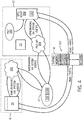
- FIG. 4 illustrates an embodiment of certain information flow and processing synchronization that may be implemented between the PPMSS 8 and the PDMSS 10 via the simulation integration system 12 and using the shared memory 18.
- the model 20 may be created to simulate a power production system, such as the system 100 described in FIG. 2 .
- the model 20 may additionally execute the API described by or otherwise included in the library system 14 and encoded in the DLL 16.
- the model 20 may interact (e.g., handshake) with certain PPMSS 8 internals 300 to simulate the system modeled, such as the system 100.
- the internals 300 may provide for input/output registration services, command and control services (e.g., step simulation, pause simulation, stop simulation, and so on), and IC data management (e.g., save/restore).
- the model 20 may interact with the internals 300 via system events, such as operating system (OS) events.
- OS operating system
- the models 20, 22 may signal each other via certain events.
- custom events such as a PSLF_CYCLE_COMMAND and a PSLF_CYCLE_COMPLETE may be used for signaling. That is, the models 20, 22 may raise the aforementioned events, as well as listen to the events raised. The presence of the events being raised may lead to certain processing logic, described in more detail below.
- the OS may additionally or alternatively trigger events based on user input,, program logic, status or activity of certain systems (e.g., shared memory 18 status, filesystem status), and so on.
- the model 20 may act as a master control for the PDMSS 10 and/or the model 22. More specifically, the model 20 may interact with the internals 300 which in turn may interface with the simulation integration system 12 to control the PDMSS 10 and/or the model 22.
- the simulation integration system 12 may include an API 302 that may be described via the library 14 and implemented in the DLL 16.
- the internals 300 and/or model 20, as well as the PPMS may establish the shared memory 18, synchronize both simulation systems PPMSS 8 and PDMSS 10 (including models 20, 22), provide for command and control services (e.g., step simulation, pause simulation, stop simulation, and so on), and IC data management (e.g., save, restore).
- the simulation integration system 12 may also use system events as described above, to handshake or otherwise interface, for example, with the internals 300 (and thus the model 20) and a PSLF API 304 (and thus the model 22).
- the PSLF API 304 may provide for services including I/O registration, command and control services, (e.g., step simulation, pause simulation, stop simulation, and so on), and IC data management (e.g., save, restore), for example, to the model 22.
- PSLF internals 306 may additionally provide for services that map I/O to the shared memory 18, for example, to enable data exchange via the shared memory 18.
- the PSLF internals 306 may additionally map command and control services (e.g., step simulation, pause simulation, stop simulation, heartbeat, and so on).
- EPCL Script system 308 may include program script(s) or executable computer code 310 to be executed by the PDMSS 10.
- the EPCL script system 308 can be used to develop customized user defined transient models of electrical controls in the power plant. It can also be used to execute PSLF 306. Indeed, the script(s) 310 may execute the PSLF API 304 to support execution of the model 22, and in some cases, to fully execute the model 22.
- the EPCL Script system 308 may interact with the PSLF API 304, for example, by handshaking via system events.
- the EPCL Script system 308 may support a scripting or interpreted language, such as EPCL.
- model 20 acts as a master to control execution of the model 22.
- the model 20 may execute at a lower frequency (e.g., 4 ms), while the model 22 may execute at a higher frequency (e.g., 2 ms).
- Model 22 execution refers to the integration of simulation time (e.g., simulating objects and sub-objects for a specified time period) by a prescribed or pre-configured integration time step.
- model 22 execution includes reading inputs, solving state and algebraic equations, and writing outputs. The inputs and outputs may include data stored in bytes 312 of the shared memory system 18.
- model 22 Because the model 22 has a smaller time step for numerical integration, the model 22 will run at a higher frequency until simulation time for that cycle equates to an integration time step for the model 20. At that time, control is relinquished to Model 20 to complete another cycle.
- inputs may be read from the shared memory system 18 that may have been written previously by the model 22, state and algebraic equations may be solved by the model 20, and the model 20 may write outputs to the memory system 18. Then control is relinquished to model 22, and so on.
- model 20, 22 execution may be synchronized and a more efficient and comprehensive simulation, for example, of systems 100 and 200 may be provided.
- the techniques herein do not depend on special hardware, e.g. reflective memory (RFM), to facilitate inter-process communication and time synchronization.
- RFM reflective memory
- FIG. 5 depicts an embodiment of a process 400 suitable for modeling and synchronizing execution of PPMSS 8 models with PDMSS 10 models.
- the process 400 may be implemented as computer executable code or instructions executable by the processor(s) 24 and stored in the memory 26.
- the process 400 may create (block 402) one or more models.
- the PPMSS 8 may include authoring tools useful in creating the PPMSS model 20.
- the PDMSS 10 may include authoring tools useful in creating the PDMSS model 22.
- the process 400 may then synchronize (block 404) execution of the models 20, 22.
- the models 20 and 22 may be synchronized via the simulation integration system 12.
- model 20 may control execution of model 22 via the API 302.
- the process 400 may raise (block 406) a system event, such as the PSLF_CYCLE_COMMAND event.
- the raising (block 406) of the system event may then signal the PDMSS 10 to use the model 22 to execute a predetermined number of time steps in a cycle 408.
- a total time to execute the predetermined number of time steps take equal time to a total time taken to execute one integration time step of the model 20.
- the model 22 may read inputs (block 410). Certain of the inputs read may be stored in the shared memory system 18. Reading may include using certain locks (e.g., mutex locks) to provide for data that is not overwritten by other process, for example, during the read.
- the model 22 may then process (block 410) the inputs. Processing the inputs (block 412) may include computing certain model equations, model logic, execution of sub-processes, solving states, and so on.
- the model 22 may then write (block 414) certain outputs. Some of the outputs may be written into the shared memory system 18.
- the write operation may additionally use locks (e.g., mutex locks) to provide for data integrity during the write operation.
- the cycle 408 of reading (block 410), processing (block 412) and writing (block 414) may be faster than the cycle 404 of the model 20. Indeed, because the model 22 has a smaller time step for numerical integration, the model 22 will run at a higher frequency until simulation time for that cycle 408 equates to an integration time step (e.g., one cycle 404) for the model 20. At that time, control is relinquished to model 20 to complete another cycle 404.
- an integration time step e.g., one cycle 404
- the process 400 may keep track or otherwise update (block 416) of a number of currently executed time steps and determine (decision 418) if the current time step count adds to a total time less than the model 20's integration step (e.g., total time in time steps is less than cycle 404). If yes (decision 418), then the model 22 may execute another cycle 408. If no (decision 418), then the process 400 may then process certain system events and wait (block 420). More specifically the process 400 may set the PSLF_CYCLE_COMMAND event to a non-signaled state, and also set the PSLF_CYCLE_COMPLETE event to a signaled state. The PDMSS 10 may then wait until the PSLF_CYCLE_COMMAND event is signaled, and continue execution synchronization via blocks 404, 410, 412, 414, and 416.
- the process 400 may complete another cycle 404 of simulation via the model 20.
- the model 20 may read inputs (block 422). Certain of the inputs read may be stored in the shared memory system 18. Reading may include using certain locks (e.g., mutex locks) to provide for data that is not overwritten by other process, for example, during the read.
- the model 20 may then process (block 424) the inputs. Processing the inputs (block 424) may include computing certain model equations, model logic, execution of sub-processes, solving states, and so on.
- the model 20 may then write (block 426) certain outputs.
- the process 400 may provide for time synchronization, data exchanges, and execution invocation.
- the model 20 may control execution of the model 22 and the simulation integration system 12 may be used to synchronize cycles 408 and 404 to enable reads and writes between the models 20 and 22 to occur in an ordered and more efficient fashion.
- PPMSS power production modeling and simulation system
- PDMSS power distribution modeling and simulation system
- data may be exchanged via a shared memory system, thus removing the need for specialized hardware such as reflective memory (RFM).
- the PPMSS model may act as a master in control of the PDMSS model, for example, via a simulation integration system.
- the simulation integration system may provide for an API suitable for control model invocation, input/output registration services, command and control services (e.g., step simulation, pause simulation, stop simulation, and so on), and IC data management (e.g., save/restore).
- the PDMSS model may include a faster execution time per simulation cycle as compared to the PPMSS model. Accordingly, the PDMSS model will run at a higher frequency until simulation time for that execution cycle equates to an integration time step for the PPMSS model, at which time control is relinquished to PPMSS to complete another cycle.
- the techniques described herein may enable simulations that improve fidelity, efficiency, and reduce overall simulation time.
Landscapes
- Engineering & Computer Science (AREA)
- Business, Economics & Management (AREA)
- Theoretical Computer Science (AREA)
- Physics & Mathematics (AREA)
- Computer Hardware Design (AREA)
- Economics (AREA)
- General Physics & Mathematics (AREA)
- Human Resources & Organizations (AREA)
- Strategic Management (AREA)
- Health & Medical Sciences (AREA)
- General Business, Economics & Management (AREA)
- Tourism & Hospitality (AREA)
- Marketing (AREA)
- Evolutionary Computation (AREA)
- Geometry (AREA)
- General Engineering & Computer Science (AREA)
- Development Economics (AREA)
- Quality & Reliability (AREA)
- Game Theory and Decision Science (AREA)
- Operations Research (AREA)
- Entrepreneurship & Innovation (AREA)
- Public Health (AREA)
- Water Supply & Treatment (AREA)
- General Health & Medical Sciences (AREA)
- Primary Health Care (AREA)
- Microelectronics & Electronic Packaging (AREA)
- Supply And Distribution Of Alternating Current (AREA)
Abstract
Description
- The subject matter disclosed herein relates to power production simulation and power distribution simulation, and more specifically, the integration of power production simulation with power distribution simulation.
- Certain systems may model and simulate power production systems, such as a power production plant, and simulate the resulting power production systems, for example, to validate and verify a new power production plant design. Likewise, certain systems may model and simulate power distribution and/or consumption, such as an electric grid and power consumptive sites electrically coupled to the grid. The power distribution and/or consumption models may be useful, for example, in simulating the transmission of power through a network, and/or the subsequent use of the power. It would be advantageous to integrate systems that model and simulate power productions systems with systems that model and simulate power distribution and/or consumption systems.
- Certain embodiments commensurate in scope with the originally claimed invention are summarized below. These embodiments are not intended to limit the scope of the claimed invention, but rather these embodiments are intended only to provide a brief summary of possible forms of the invention. Indeed, the invention may encompass a variety of forms that may be similar to or different from the embodiments set forth below.
- In a first embodiment, a system includes a processor. The processor is configured to provide for time synchronization between execution of a power production modeling and simulation system (PPMSS) model and a power distribution modeling and simulation system (PDMSS) model, wherein the PPMSS model comprises a power production system simulation and wherein the PDMSS model comprises a power distribution system simulation.
- In a second embodiment, a method includes executing, via a processor, a simulation integration system configured to provide for time synchronization between execution of a power production modeling and simulation system (PPMSS) model and a power distribution modeling and simulation system (PDMSS) model, wherein the PPMSS model comprises a power production system simulation and wherein the PDMSS model comprises a power distribution system simulation.
- In a third embodiment, a tangible, non-transitory, computer-readable medium includes instructions that when executed by a processor cause the processor to execute a simulation integration system configured to provide for time synchronization between execution of a power production modeling and simulation system (PPMSS) model and a power distribution modeling and simulation system (PDMSS) model, wherein the PPMSS model comprises a power production system simulation and wherein the PDMSS model comprises a power distribution system simulation.
- These and other features, aspects, and advantages of the present invention will become better understood when the following detailed description is read with reference to the accompanying drawings in which like characters represent like parts throughout the drawings, wherein:
-
FIG. 1 illustrates an embodiment of a power production modeling and simulation system (PPMSS) operatively coupled to a power distribution modeling and simulation system (PDMSS) via a simulation integration system; -
FIG. 2 illustrates an embodiment of an integrated gasification combined cycle (IGCC) power plant system that may be modeled by the PPMSS ofFIG. 1 ; -
FIG. 3 Illustrates an embodiment of a power distribution grid that may be modeled by the PDMSS ofFIG. 1 ; -
FIG. 4 illustrates an embodiment of certain information flow and processing synchronization that may be implemented between the PPMSS and the PDMSS ofFIG. 1 , via the simulation integration system using shared memory; and -
FIG. 5 shows and embodiment of a process suitable for modeling and synchronizing execution of PPMSS models with PDMSS models. - One or more specific embodiments of the present invention will be described below. In an effort to provide a concise description of these embodiments, all features of an actual implementation may not be described in the specification. It should be appreciated that in the development of any such actual implementation, as in any engineering or design project, numerous implementation-specific decisions must be made to achieve the developers' specific goals, such as compliance with system-related and business-related constraints, which may vary from one implementation to another. Moreover, it should be appreciated that such a development effort might be complex and time consuming, but would nevertheless be a routine undertaking of design, fabrication, and manufacture for those of ordinary skill having the benefit of this disclosure.
- When introducing elements of various embodiments of the present invention, the articles "a," "an," "the," and "said" are intended to mean that there are one or more of the elements. The terms "comprising," "including," and "having" are intended to be inclusive and mean that there may be additional elements other than the listed elements.
- The techniques described herein provide for systems and methods that more efficiently integrate systems that include transient models, for example, of power production and generation, with systems that include transient models, for example, of power distribution and/or consumption. In one embodiment, a transient model of power generation and a transient model of power distribution and/or consumption may be integrated via software without being dependent on special hardware, e.g. reflective memory (RFM), to facilitate inter-process communication and time synchronization between both models. The system including the power production and generation model, referred to herein as the power production modeling and simulation system (PPMSS), may act as a master or host, and may control when the system including the power distribution model may execute the power distribution model. The system including the power distribution model is referred to herein as the power distribution modeling and simulation system (PDMSS).
- Model execution may refer to an integration of simulation time by a prescribed or pre-configured integration time step. At a high level, during model execution the PDMSS will read inputs, solve state and algebraic equations, and write outputs. The PDMSS will include a smaller time step for numerical integration as compared to the PPMSS. Accordingly, the PDMSS model will run at a higher frequency until simulation time for that execution cycle equates to an integration time step for the PPMSS model, at which time control is relinquished to PPMSS to complete another cycle. A frequency of data exchange is exclusively determined by the integration time step configured in each model. Data exchange may preferably include shared memory exchanges, but other inter process communication (IPC) techniques may also be used, including named pipes, sockets, message passing, message queues, and the like. By providing for the PPMSS master and the smaller time step PDMSS integrated via a simulation integration system, a more reliable and efficient simulation of power production and subsequent power distribution may be enabled.
- Turning now to
FIG. 1 , the figure illustrates an embodiment of aPPMSS 8 operatively coupled to aPDMSS 10 via asimulation integration system 12. In certain embodiments, thesimulation integration system 12 may be included in thePPMSS 8. In other embodiments, thesimulation integration system 12 may be included in the PDMSS 10. In yet other embodiments, thesimulation integration system 12 may be a standalone system, or included in another system not shown. Thesimulation integration system 12 may further include alibrary system 14 and a dynamic link library (DLL)system 16. Thelibrary system 14 may provide for an application programming interface (API) suitable for interfacing between thePPMSS 8 and the PDMSS 10. For example, the API may expose certain functions, subroutines, programming interfaces, system calls (e.g., operating system functions and/or subroutines), constants, and the like, useful in exchanging data between thePPMSS 8 and the PDMSS 10, as further described below. TheDLL system 16 may include executable code or instructions that may be loaded, for example, at runtime, by thePPMSS 8 and/or the PDMSS 10 to execute the functions, subroutines, programming interfaces, system calls, constants, and the like, described via thelibrary system 14. - A shared
memory system 18 is also illustrated. In operation thePPMSS 8 and the PDMSS 10 may share data via the sharedmemory system 18. For example, thesimulation integration system 12 may mediate between thePPMSS 8 and the PDMSS 10 to update data every simulation integration time step as a simulation advances in time. Data included in the sharedmemory system 18 may be protected by system locks (mutex) to ensure data integrity. Time synchronization (e.g., handshaking) betweenmodels transient model 20 executing within thePPMSS 8 is the master and thetransient model 22 executing within thePDMSS 10 is the slave. That is, thetransient model 20 determines when to invoke thetransient model 22 for further execution. In one embodiment, thetransient model 22 executes at a higher frequency when compared to thetransient model 20, e.g. thetransient model 22 may include an integration time step of 4 ms whereas thetransient model 20 may include an integration time step of 2 ms. Accordingly, themodel 22 may execute two cycles when compared to themodel 20. It is to be noted that other frequencies may be used, for example, such that themodel 22 includes a lower integration time step when compared to themodel 20. - In the depicted embodiment, the PPMSS 8 system is designed and used to develop large-scale, high-fidelity, transient system models of physical systems or processes typically found in the power industry. Examples of the
models 20 may include combined-cycle power plant (CCPP) as well as larger and more complex, integrated gasification combined-cycle power plants (IGCC). These CCPP and/or IGCC systems can be comprised of gas turbines, steam turbines, heat recover steam generators (HRSG), and other types of equipment, e.g. pipes, valves, pumps, vessels, heat exchangers, and the like. In one embodiment, the PPMSS 8 may include Easy5™, available from MSC Software of Newport Beach, California, U.S.A. The PDMSS 10 system is designed and used to develop large-scale, high-fidelity, transient system models of electrical systems (e.g., electrical power grids) or processes typically found in the energy industry. -
Models 22 may include power flow and stability models that includes integration with geographic information systems (e.g., Google Earth) to provide for analysis useful in detailing the flow of electrical power and the stability of networks delivering the power.Models 22 may include transmission lines, transformers, switching devices, network graphs, and so on, useful in analyzing the transmission and distribution of power. In one embodiment, the PDMSS 10 may include a Positive Sequence Load Flow (PSLF) software, available from General Electric International Inc., of Schenectady, New York, U.S.A. ThePDMSS 10 may apply a PSLF analysis that may include solving certain electrical network systems by using, for example, a Newton-Raphson and Differential Algebraic techniques. The Newton-Raphson technique may find successively better approximations to roots (or zeroes) of a real-valued function x: f(x) = 0. InFIG. 1 , thePPMSS 8 and thePDMSS 10 may be software system that may be executable, for example, by physical processor(s) 24 and stored in amemory 26. The processor(s) 24 and thememory 26 may be included in acomputing system 28. For example, thecomputing system 28 may include a workstation, a laptop, a desktop, a notebook, a tablet, or a cloud-computing system. By integrating themodel 20 with themodel 22 in a single simulation environment, and by sharing data through the shared memory, a more efficient and higher fidelity simulation of certain power production and power distribution systems may be enabled. - It may be useful to further describe certain of the systems that may be included in the
models FIGS. 2 and3 describe certain power production and power distribution systems respectively. For example, and turning now toFIG. 2 , the figure depicts an embodiment of anIGCC power plant 100 that may be modeled by themodel 20. In the depicted embodiment, theIGCC power plant 100 may produce and burn a synthetic gas, i.e., a syngas. Elements of theIGCC power plant 100 may include afuel source 102, such as a carbonaceous feedstock, that may be utilized as a source of energy for theIGCC power plant 100. Thefuel source 102 may include coal, petroleum coke, biomass, wood-based materials, agricultural wastes, tars, oven gas, orimulsion, lignite, and asphalt, or other carbon containing items. - The fuel of the
fuel source 102 may be passed to afeedstock preparation unit 104. Thefeedstock preparation unit 104 may, for example, resize or reshape thefuel source 102 by chopping, milling, shredding, pulverizing, briquetting, or palletizing thefuel source 102 to generate feedstock. Additionally, water, or other suitable liquids may be added to thefuel source 102 in thefeedstock preparation unit 104 to create slurry feedstock. In certain embodiments, no liquid is added to the fuel source, thus yielding dry feedstock. The feedstock may be conveyed into agasifier 106 for use in gasification operations. - The
gasifier 106 may convert the feedstock into a syngas, e.g., a combination of carbon monoxide and hydrogen. This conversion may be accomplished by subjecting the feedstock to a controlled amount of any moderator and limited oxygen at elevated pressures (e.g., from approximately 600 pounds per square inch gauge (PSIG) - 1200 PSIG) and elevated temperatures (e.g., approximately 2200° F - 2700° F), depending on the type of feedstock used. The heating of the feedstock during a pyrolysis process may generate a solid (e.g., char) and residue gases (e.g., carbon monoxide, hydrogen, and nitrogen). - A combustion process may then occur in the
gasifier 106. The combustion may include introducing oxygen to the char and residue gases. The char and residue gases may react with the oxygen to form CO2 and carbon monoxide (CO), which provides heat for the subsequent gasification reactions. The temperatures during the combustion process may range from approximately 2200° F to approximately 2700° F. In addition, steam may be introduced into thegasifier 106. Thegasifier 106 utilizes steam and limited oxygen to allow some of the feedstock to be burned to produce carbon monoxide and energy, which may drive a second reaction that converts further feedstock to hydrogen and additional carbon dioxide. - In this way, a resultant gas is manufactured by the
gasifier 106. This resultant gas may include approximately 85% of carbon monoxide and hydrogen in equal proportions, as well as Argon, CH4, HCl, HF, COS, NH3, HCN, and H2S (based on the sulfur content of the feedstock). This resultant gas may be termed untreated syngas, since it contains, for example, H2S. Thegasifier 106 may also generate waste, such asslag 108, which may be a wet ash material. Thisslag 108 may be removed from thegasifier 106 and disposed of, for example, as road base or as another building material. To treat the untreated syngas, agas treatment unit 110 may be utilized. In one embodiment, thegas treatment unit 110 may include one or more water gas shift reactors. The water gas shift reactors may aid in elevating the level of hydrogen (H2) and CO2 in the fuel by converting the CO and H2O in the syngas into CO2 and H2 (e.g., sour shifting). Thegas treatment unit 110 may also scrub the untreated syngas to remove the HCl, HF, COS, HCN, and H2S from the untreated syngas, which may include separation ofsulfur 111 in asulfur processor 112 component of thegas treatment unit 110. Furthermore, thegas treatment unit 110 may separatesalts 113 from the untreated syngas via awater treatment unit 114 that may utilize water purification techniques to generateusable salts 113 from the untreated syngas. Subsequently, the gas from thegas treatment unit 110 may include treated syngas, (e.g., thesulfur 111 has been removed from the syngas), with trace amounts of other chemicals, e.g., NH3 (ammonia) and CH4 (methane). - A
gas processor 115 may be used to remove additionalresidual gas components 116, such as ammonia and methane, as well as methanol or any residual chemicals from the treated syngas. Argon may also be recovered. Argon is a valuable product which may be recovered using, for example, cryogenic techniques. However, removal of residual gas components from the treated syngas is optional, since the treated syngas may be utilized as a fuel even when containing the residual gas components, e.g., tail gas. - The treated syngas may be then transmitted to a
combustor 125, e.g., a combustion chamber, of thegas turbine engine 126 as combustible fuel. TheIGCC power plant 100 may further include an air separation unit (ASU) 128. TheASU 128 may operate to separate air into component gases by, for example, distillation techniques. TheASU 128 may separate oxygen from the air supplied to it from asupplemental air compressor 129, and theASU 128 may transfer the separated oxygen to thegasifier 106. Additionally theASU 128 may transmit separated nitrogen to a diluent nitrogen (DGAN)compressor 130. - The
DGAN compressor 130 may compress the nitrogen received from theASU 128 at least to pressure levels equal to those in thecombustor 125, so as not to interfere with the proper combustion of the syngas. Thus, once theDGAN compressor 130 has adequately compressed the nitrogen to a proper level, theDGAN compressor 130 may transmit the compressed nitrogen to thecombustor 125 of thegas turbine engine 126. The nitrogen may be used as a diluent to facilitate control of emissions, for example. - As described previously, the compressed nitrogen may be transmitted from the
DGAN compressor 130 to thecombustor 125 of thegas turbine engine 126. Thegas turbine engine 126 may include aturbine 132, adrive shaft 133 and acompressor 134, as well as thecombustor 125. Thecombustor 125 may receive fuel, such as syngas, which may be injected under pressure from fuel nozzles. This fuel may be mixed with compressed air as well as compressed nitrogen from theDGAN compressor 130, and combusted withincombustor 125. This combustion may create hot pressurized exhaust gases. - The
combustor 125 may direct the exhaust gases towards an exhaust outlet of theturbine 132. As the exhaust gases from thecombustor 125 pass through theturbine 132, the exhaust gases force turbine blades in theturbine 132 to rotate thedrive shaft 133 along an axis of thegas turbine engine 126. As illustrated, thedrive shaft 133 is connected to various components of thegas turbine engine 126, including thecompressor 134. - The
drive shaft 133 may connect theturbine 132 to thecompressor 134 to form a rotor. Thecompressor 134 may include blades coupled to thedrive shaft 133. Thus, rotation of turbine blades in theturbine 132 may cause thedrive shaft 133 connecting theturbine 132 to thecompressor 134 to rotate blades within thecompressor 134. This rotation of blades in thecompressor 134 causes thecompressor 134 to compress air received via an air intake in thecompressor 134. The compressed air may then be fed to thecombustor 125 and mixed with fuel and compressed nitrogen to allow for higher efficiency combustion. Driveshaft 133 may also be connected to aload 136, which may be a stationary load, such as an electrical generator for producing electrical power, for example, in a power plant. Indeed, theload 136 may be any suitable device that is powered by the rotational output of thegas turbine engine 126. - The
IGCC power plant 100 also may include asteam turbine engine 138 and a heat recovery steam generation (HRSG)system 139. Thesteam turbine engine 138 may drive asecond load 140. Thesecond load 140 may also be an electrical generator for generating electrical power. However, both the first andsecond loads gas turbine engine 126 andsteam turbine engine 138. In addition, although thegas turbine engine 126 andsteam turbine engine 138 may driveseparate loads gas turbine engine 126 andsteam turbine engine 138 may also be utilized in tandem to drive a single load via a single shaft. The specific configuration of thesteam turbine engine 138, as well as thegas turbine engine 126, may be implementation-specific and may include any combination of sections. - The
system 100 may also include theHRSG 139. Heated exhaust gas from thegas turbine engine 126 may be transported into theHRSG 139 and used to heat water and produce steam used to power thesteam turbine engine 138. Exhaust from, for example, a low-pressure section of thesteam turbine engine 138 may be directed into acondenser 142. Thecondenser 142 may utilize thecooling tower 124 to exchange heated water for chilled water. Thecooling tower 124 acts to provide cool water to thecondenser 142 to aid in condensing the steam transmitted to thecondenser 142 from thesteam turbine engine 138. Condensate from thecondenser 142 may, in turn, be directed into theHRSG 139. Again, exhaust from thegas turbine engine 126 may also be directed into theHRSG 139 to heat the water from thecondenser 142 and produce steam. - In combined cycle power plants such as
IGCC power plant 100, hot exhaust may flow from thegas turbine engine 126 and pass to theHRSG 139, where it may be used to generate high-pressure, high-temperature steam. The steam produced by theHRSG 139 may then be passed through thesteam turbine engine 138 for power generation. In addition, the produced steam may also be supplied to any other processes where steam may be used, such as to thegasifier 106. Thegas turbine engine 126 generation cycle is often referred to as the "topping cycle," whereas thesteam turbine engine 126 generation cycle is often referred to as the "bottoming cycle." By combining these two cycles as illustrated inFIG. 1 , theIGCC power plant 100 may lead to greater efficiencies in both cycles. In particular, exhaust heat from the topping cycle may be captured and used to generate steam for use in the bottoming cycle. - Any one or more of the systems in the
IGCC power plant 100 shown, as well as certain equipment not shown, such as valves, pumps, positioners, actuators, sensors, control systems, and the like may be modeled via thePPMSS 8 and/or themodel 20. Likewise,FIG. 3 depicts and embodiment of a system, such as apower grid 208, that may be modeled by thePDMSS 10 and/or themodel 22. - The
power grid 208 may include one ormore utilities 210. Theutility 210 may provide for power production and oversight operations of thepower grid system 208. Utility control centers 212 may monitor and direct power produced by one or morepower generation stations 214 andwind power systems 216. Thepower generation stations 214 may include conventional power generation stations, such as power generation stations using gas, coal, biomass, and other carbonaceous products for fuel. Thepower generation stations 214 may additionally include alternative power generation stations using solar power, hydroelectric power, geothermal power, and other alternative sources of power (e.g., renewable energy) to produce electricity. For example, other infrastructure components may include a waterpower producing plant 220 and geothermalpower producing plant 222. Waterpower producing plants 220 may provide for hydroelectric power generation, and geothermalpower producing plants 222 may provide for geothermal power generation. - The power generated by the
power generation stations power transmission grids 224. Apower transmission grid 224 may cover a broad geographic region or regions, such as one or more municipalities, states, or countries. Thetransmission grid 224 may also be a single phase alternating current (AC) system, but most generally may be a three-phase AC current system. As depicted, thepower transmission grid 224 may include a series of towers to support a series of overhead electrical conductors in various configurations. For example, extreme high voltage (EHV) conductors may be arranged in a three conductor bundle, having a conductor for each of three phases. Thepower transmission grid 224 may support nominal system voltages in the ranges of 110 kilovolts (kV) to 765 kilovolts (kV). In the depicted embodiment, thepower transmission grid 24 may be electrically coupled to distribution systems (e.g., power distribution substations 226). Apower distribution substation 226 may include transformers to transform the voltage of the incoming power from a transmission voltage (e.g., 765 kV, 500kV, 345kV, or 138kV) to primary (e.g., 13.8kV or 4160V) and secondary (e.g., 480V, 230V, or 120V) distribution voltages. - Advanced metering infrastructure meters (e.g., smart meters) 230 may be used to monitor and communicate power related information based on electric power delivered to
commercial consumers 232 andresidential consumers 234. For example, thesmart meters 230 may include two-way communications with thegrid system 208 and theutilities 210 suitable for communicating a variety of information, including power usage, tampering, power outage notification, power quality monitoring, and the like. Thesmart meters 230 may additionally receive information, for example, demand response actions, time-of-use pricing information, remote service disconnects, and the like. - The
customers power consuming devices 236, such as household appliances, industrial machinery, communications equipment, and the like. In certain embodiments, thepower consuming devices 236 may be communicatively coupled to thegrid system 208, theutilities 210, and/or themeters 230. For example, thepower consuming devices 236 may include switches that may be actuated remotely to turn on/off thedevices 236 and/or to vary power consumption (e.g., lower or raise heating ventilation and air conditioning [HVAC] temperature set points). Thesmart meters 230 and thepower consuming devices 236 may be communicatively coupled, for example, through a home area network (HAN), (for residential customers 234), wireless area network (WAN), powerline network, local area network (LAN), mesh network and the like. As mentioned above, power produced by thepower generation systems model 20 and/or thePPMSS 8. The remainder of thesystem 208, and more specifically, thegrid 224, may be modeled via themodel 22 and/or thePDMSS 10. It is to be noted that in certain embodiments themodel 22 models the electrical components or portions of thepower plant 100, such asturbine 126,HRSG 139, electrical generators, electrical motors, auxiliary transformers, step up transformers, and the like, in addition tosystem 208. Accordingly, as a simulation that includes themodels simulation integration system 12 may be used to perform time synchronization, data exchanges, execution invocation, and so on, as described in more detail below. -
FIG. 4 illustrates an embodiment of certain information flow and processing synchronization that may be implemented between thePPMSS 8 and thePDMSS 10 via thesimulation integration system 12 and using the sharedmemory 18. In the depicted embodiment themodel 20 may be created to simulate a power production system, such as thesystem 100 described inFIG. 2 . In addition to implementing objects representative of the various components of thesystem 100, and simulating said objects, themodel 20 may additionally execute the API described by or otherwise included in thelibrary system 14 and encoded in theDLL 16. In operations, themodel 20 may interact (e.g., handshake) withcertain PPMSS 8internals 300 to simulate the system modeled, such as thesystem 100. For example, theinternals 300 may provide for input/output registration services, command and control services (e.g., step simulation, pause simulation, stop simulation, and so on), and IC data management (e.g., save/restore). In certain embodiments, themodel 20 may interact with theinternals 300 via system events, such as operating system (OS) events. For example, themodels models memory 18 status, filesystem status), and so on. - As the
model 20 executes its simulation supported by theinternals 300, themodel 20 may act as a master control for the PDMSS 10 and/or themodel 22. More specifically, themodel 20 may interact with theinternals 300 which in turn may interface with thesimulation integration system 12 to control thePDMSS 10 and/or themodel 22. As mentioned above, thesimulation integration system 12 may include anAPI 302 that may be described via thelibrary 14 and implemented in theDLL 16. By using theAPI 302, theinternals 300 and/ormodel 20, as well as the PPMS may establish the sharedmemory 18, synchronize both simulation systems PPMSS 8 and PDMSS 10 (includingmodels 20, 22), provide for command and control services (e.g., step simulation, pause simulation, stop simulation, and so on), and IC data management (e.g., save, restore). In the depicted embodiment, thesimulation integration system 12 may also use system events as described above, to handshake or otherwise interface, for example, with the internals 300 (and thus the model 20) and a PSLF API 304 (and thus the model 22). - The
PSLF API 304 may provide for services including I/O registration, command and control services, (e.g., step simulation, pause simulation, stop simulation, and so on), and IC data management (e.g., save, restore), for example, to themodel 22.PSLF internals 306 may additionally provide for services that map I/O to the sharedmemory 18, for example, to enable data exchange via the sharedmemory 18. The PSLF internals 306 may additionally map command and control services (e.g., step simulation, pause simulation, stop simulation, heartbeat, and so on). Also shown is anEPCL Script system 308. TheEPCL Script system 308 may include program script(s) orexecutable computer code 310 to be executed by thePDMSS 10. TheEPCL script system 308 can be used to develop customized user defined transient models of electrical controls in the power plant. It can also be used to executePSLF 306. Indeed, the script(s) 310 may execute thePSLF API 304 to support execution of themodel 22, and in some cases, to fully execute themodel 22. TheEPCL Script system 308 may interact with thePSLF API 304, for example, by handshaking via system events. TheEPCL Script system 308 may support a scripting or interpreted language, such as EPCL. - In the depicted embodiment, the
model 20 acts as a master to control execution of themodel 22. For example, themodel 20 may execute at a lower frequency (e.g., 4 ms), while themodel 22 may execute at a higher frequency (e.g., 2 ms).Model 22 execution refers to the integration of simulation time (e.g., simulating objects and sub-objects for a specified time period) by a prescribed or pre-configured integration time step. In one embodiment,model 22 execution includes reading inputs, solving state and algebraic equations, and writing outputs. The inputs and outputs may include data stored inbytes 312 of the sharedmemory system 18. Because themodel 22 has a smaller time step for numerical integration, themodel 22 will run at a higher frequency until simulation time for that cycle equates to an integration time step for themodel 20. At that time, control is relinquished to Model 20 to complete another cycle. During themodel 20 cycle, inputs may be read from the sharedmemory system 18 that may have been written previously by themodel 22, state and algebraic equations may be solved by themodel 20, and themodel 20 may write outputs to thememory system 18. Then control is relinquished to model 22, and so on. By this interplay of execution betweenmodel 20 andmodel 22 as mediated by thesimulation integration system 12,model systems memory system 18, the techniques herein do not depend on special hardware, e.g. reflective memory (RFM), to facilitate inter-process communication and time synchronization. -
FIG. 5 depicts an embodiment of aprocess 400 suitable for modeling and synchronizing execution ofPPMSS 8 models withPDMSS 10 models. Theprocess 400 may be implemented as computer executable code or instructions executable by the processor(s) 24 and stored in thememory 26. In the depicted embodiment, theprocess 400 may create (block 402) one or more models. For example, thePPMSS 8 may include authoring tools useful in creating thePPMSS model 20. Likewise, thePDMSS 10 may include authoring tools useful in creating thePDMSS model 22. Theprocess 400 may then synchronize (block 404) execution of themodels - In one embodiment, the
models simulation integration system 12. For example,model 20 may control execution ofmodel 22 via theAPI 302. More specifically, when themodel 20 has completed oneintegration time step 404, theprocess 400 may raise (block 406) a system event, such as the PSLF_CYCLE_COMMAND event. The raising (block 406) of the system event may then signal thePDMSS 10 to use themodel 22 to execute a predetermined number of time steps in acycle 408. In one embodiment, a total time to execute the predetermined number of time steps take equal time to a total time taken to execute one integration time step of themodel 20. - During execution of the predetermined time steps (e.g., cycle 408), the
model 22 may read inputs (block 410). Certain of the inputs read may be stored in the sharedmemory system 18. Reading may include using certain locks (e.g., mutex locks) to provide for data that is not overwritten by other process, for example, during the read. Themodel 22 may then process (block 410) the inputs. Processing the inputs (block 412) may include computing certain model equations, model logic, execution of sub-processes, solving states, and so on. Themodel 22 may then write (block 414) certain outputs. Some of the outputs may be written into the sharedmemory system 18. The write operation may additionally use locks (e.g., mutex locks) to provide for data integrity during the write operation. As mentioned earlier, thecycle 408 of reading (block 410), processing (block 412) and writing (block 414), may be faster than thecycle 404 of themodel 20. Indeed, because themodel 22 has a smaller time step for numerical integration, themodel 22 will run at a higher frequency until simulation time for thatcycle 408 equates to an integration time step (e.g., one cycle 404) for themodel 20. At that time, control is relinquished to model 20 to complete anothercycle 404. - Accordingly, the
process 400 may keep track or otherwise update (block 416) of a number of currently executed time steps and determine (decision 418) if the current time step count adds to a total time less than themodel 20's integration step (e.g., total time in time steps is less than cycle 404). If yes (decision 418), then themodel 22 may execute anothercycle 408. If no (decision 418), then theprocess 400 may then process certain system events and wait (block 420). More specifically theprocess 400 may set the PSLF_CYCLE_COMMAND event to a non-signaled state, and also set the PSLF_CYCLE_COMPLETE event to a signaled state. ThePDMSS 10 may then wait until the PSLF_CYCLE_COMMAND event is signaled, and continue execution synchronization viablocks - When the
process 400 detects the PSLF_CYCLE_COMPLETE event, theprocess 400 may complete anothercycle 404 of simulation via themodel 20. As shown, themodel 20 may read inputs (block 422). Certain of the inputs read may be stored in the sharedmemory system 18. Reading may include using certain locks (e.g., mutex locks) to provide for data that is not overwritten by other process, for example, during the read. Themodel 20 may then process (block 424) the inputs. Processing the inputs (block 424) may include computing certain model equations, model logic, execution of sub-processes, solving states, and so on. Themodel 20 may then write (block 426) certain outputs. As mentioned above, theprocess 400 may provide for time synchronization, data exchanges, and execution invocation. For example, by using theAPI 302, themodel 20 may control execution of themodel 22 and thesimulation integration system 12 may be used to synchronizecycles models - Technical effects of the invention include integrating a power production modeling and simulation system (PPMSS) model with a power distribution modeling and simulation system (PDMSS) model via time synchronization, data exchanges, and execution invocation. In certain embodiments, data may be exchanged via a shared memory system, thus removing the need for specialized hardware such as reflective memory (RFM). The PPMSS model may act as a master in control of the PDMSS model, for example, via a simulation integration system. The simulation integration system may provide for an API suitable for control model invocation, input/output registration services, command and control services (e.g., step simulation, pause simulation, stop simulation, and so on), and IC data management (e.g., save/restore). The PDMSS model may include a faster execution time per simulation cycle as compared to the PPMSS model. Accordingly, the PDMSS model will run at a higher frequency until simulation time for that execution cycle equates to an integration time step for the PPMSS model, at which time control is relinquished to PPMSS to complete another cycle. By providing for time synchronization, data exchanges, and execution invocation, the techniques described herein may enable simulations that improve fidelity, efficiency, and reduce overall simulation time.
- This written description uses examples to disclose the invention, including the best mode, and also to enable any person skilled in the art to practice the invention, including making and using any devices or systems and performing any incorporated methods. The patentable scope of the invention is defined by the claims, and may include other examples that occur to those skilled in the art. Such other examples are intended to be within the scope of the claims if they have structural elements that do not differ from the literal language of the claims, or if they include equivalent structural elements with insubstantial differences from the literal language of the claims.
- Various aspects and embodiments of the present invention are defined by the following clauses:
- 1. A system, comprising;
a processor configured to execute:- a simulation integration system configured to provide for time synchronization between execution of a power production modeling and simulation system (PPMSS) model and a power distribution modeling and simulation system (PDMSS) model, wherein the PPMSS model comprises a power production system simulation and wherein the PDMSS model comprises a power distribution system simulation.
- 2. The system of clause 1, wherein the PPMSS model is configured to provide for a master control of the PDMSS model.
- 3. The system of clause 2, wherein the PPMSS model is configured to invoke execution of the PDMSS model via a system event.
- 4. The system of clause 2, wherein the PDMSS model is configured to execute at a higher frequency compared to the PPMSS model until a simulation time for a PDMSS model execution cycle is equal to an integration time step for the PPMSS model.
- 5. The system of clause 4, wherein the simulation integration system is configured to relinquish control to the PPMSS model to begin completion of another PPMSS model simulation cycle when the simulation time is equal to the integration time step.
- 6. The system of clause 1, comprising a PDMSS having the PDMSS model, wherein the PDMSS comprises a Positive Sequence Load Flow (PSLF) analysis, wherein the PSLF analysis comprises evaluating an electrical network using a Newton-Raphson technique.
- 7. The system of clause 1, comprising a shared memory system, wherein the PPMSS model and the PDMSS model are configured to exchange data via the shared memory system.
- 8. The system of clause 7, wherein the PDMSS model exchanges the data via a script system that includes a script language.
- 9. The system of clause 1, wherein the PPMSS model and the PDMSS model communicate with the simulation integration system via system events.
- 10. The system of clause 1, wherein the PPMSS model comprises a gas turbine simulation, an integrated gasification combined cycle (IGCC) plant simulation, or a combination thereof.
- 11. A method, comprising:
- executing, via a processor, a simulation integration system configured to provide for time synchronization between execution of a power production modeling and simulation system (PPMSS) model and a power distribution modeling and simulation system (PDMSS) model, wherein the PPMSS model comprises a power production system simulation and wherein the PDMSS model comprises a power distribution system simulation.
- 12. The method of clause 11, wherein the PPMSS model is configured to provide for a master control of the PDMSS model.
- 13. The method of
clause 12, wherein the PPMSS model is configured to invoke execution of the PDMSS model via a system event. - 14. The method of
clause 12, wherein the PDMSS model is configured to execute at a higher frequency compared to the PPMSS model until a simulation time for a PDMSS model execution cycle is equal to an integration time step for the PPMSS model. - 15. The method of
clause 14, wherein the simulation integration system is configured to relinquish control to the PPMSS model to begin completion of another PPMSS model simulation cycle when the simulation time is equal to the integration time step. - 16. A tangible, non-transitory, computer-readable medium comprising instructions that when executed by a processor cause the processor to:
- execute a simulation integration system configured to provide for time synchronization between execution of a power production modeling and simulation system (PPMSS) model and a power distribution modeling and simulation system (PDMSS) model, wherein the PPMSS model comprises a power production system simulation and wherein the PDMSS model comprises a power distribution system simulation.
- 17. The tangible, non-transitory, computer-readable medium of
clause 16, wherein the PPMSS model is configured to provide for a master control of the PDMSS model. - 18. The tangible, non-transitory, computer-readable medium of
clause 16, wherein the PDMSS model is configured to execute at a higher frequency compared to the PPMSS model until a simulation time for a PDMSS model execution cycle is equal to an integration time step for the PPMSS model. - 19. The tangible, non-transitory, computer-readable medium of
clause 16, wherein the PDMSS model comprises a Positive Sequence Load Flow (PSLF) analysis, wherein the PSLF analysis comprises evaluating an electrical network using a Newton-Raphson technique,differential algebraic equations, or a combination thereof. - 20. The tangible, non-transitory, computer-readable medium of
clause 16, wherein the PPMSS model comprises a gas turbine simulation, an integrated gasification combined cycle (IGCC) plant simulation, or a combination thereof.
Claims (15)
- A system (28), comprising;
a processor (24) configured to execute:a simulation integration system (12) configured to provide for time synchronization between execution of a power production modeling and simulation system (PPMSS) model (20) and a power distribution modeling and simulation system (PDMSS) model (22), wherein the PPMSS model (20) comprises a power production system simulation and wherein the PDMSS model (22) comprises a power distribution system simulation. - The system (28), of claim 1, wherein the PPMSS model (20) is configured to provide for a master control of the PDMSS model (22).
- The system (28), of claim 1, comprising a PDMSS (10) having the PDMSS model (22), wherein the PDMSS (10) comprises a Positive Sequence Load Flow (PSLF) (304,306) analysis, wherein the PSLF (304,306) analysis comprises evaluating an electrical network using a Newton-Raphson technique.
- The system (28), of claim 1, comprising a shared memory system (18), wherein the PPMSS model (20) and the PDMSS model (22) are configured to exchange data via the shared memory system (18).
- The system (28), of claim 1, wherein the PPMSS model (20) and the PDMSS model (22) communicate with the simulation integration system (12) via system events.
- The system (28), of claim 1, wherein the PPMSS model (20) comprises a gas turbine (126) simulation, an integrated gasification combined cycle (IGCC) plant (100) simulation, or a combination thereof.
- A method (400), comprising:executing, via a processor (24), a simulation integration system (12) configured to provide for time synchronization between execution of a power production modeling and simulation system (PPMSS) model (20) and a power distribution modeling and simulation system (PDMSS) model (22), wherein the PPMSS model (20) comprises a power production system simulation and wherein the PDMSS model (22) comprises a power distribution system simulation.
- The method (400), of claim 7, wherein the PPMSS model (20) is configured to provide for a master control of the PDMSS model (22).
- The method (400), of claim 8, wherein the PPMSS model (20) is configured to invoke execution of the PDMSS model (22) via a system event.
- The method (400), of claim 8, wherein the PDMSS model (22) is configured to execute at a higher frequency compared to the PPMSS model (20) until a simulation time for a PDMSS model (22) execution cycle is equal to an integration time step for the PPMSS model (20).
- A tangible, non-transitory, computer-readable medium comprising instructions that when executed by a processor (24) cause the processor (24) to:execute a simulation integration system (12) configured to provide for time synchronization between execution of a power production modeling and simulation system (PPMSS) model (20) and a power distribution modeling and simulation system (PDMSS) model (22), wherein the PPMSS model (20) comprises a power production system simulation and wherein the PDMSS model (22) comprises a power distribution system simulation.
- The tangible, non-transitory, computer-readable medium of claim 11, wherein the PPMSS model (20) is configured to provide for a master control of the PDMSS model (22).
- The tangible, non-transitory, computer-readable medium of claim 11, wherein the PDMSS model (22) is configured to execute at a higher frequency compared to the PPMSS model (20) until a simulation time for a PDMSS model (22) execution cycle is equal to an integration time step (404) for the PPMSS model (20).
- The tangible, non-transitory, computer-readable medium of claim 11, wherein the PDMSS model (22) comprises a Positive Sequence Load Flow (PSLF) (304,306) analysis, wherein the PSLF (304,306) analysis comprises evaluating an electrical network using a Newton-Raphson technique,differential algebraic equations, or a combination thereof.
- The tangible, non-transitory, computer-readable medium of claim 11, wherein the PPMSS model (20) comprises a gas turbine (126) simulation, an integrated gasification combined cycle (IGCC) plant (100) simulation, or a combination thereof.
Applications Claiming Priority (1)
| Application Number | Priority Date | Filing Date | Title |
|---|---|---|---|
| US15/201,003 US10372847B2 (en) | 2016-07-01 | 2016-07-01 | Systems and methods to integrate power production simulation with power distribution simulation |
Publications (1)
| Publication Number | Publication Date |
|---|---|
| EP3264357A1 true EP3264357A1 (en) | 2018-01-03 |
Family
ID=59215548
Family Applications (1)
| Application Number | Title | Priority Date | Filing Date |
|---|---|---|---|
| EP17177321.1A Ceased EP3264357A1 (en) | 2016-07-01 | 2017-06-22 | Systems and methods to integrate power production simulation with power distribution simulation |
Country Status (2)
| Country | Link |
|---|---|
| US (1) | US10372847B2 (en) |
| EP (1) | EP3264357A1 (en) |
Cited By (3)
| Publication number | Priority date | Publication date | Assignee | Title |
|---|---|---|---|---|
| CN109582479A (en) * | 2018-12-05 | 2019-04-05 | 上海航天计算机技术研究所 | A kind of OpenDDS distributed communication method based on reflective memory card |
| EP3708768A1 (en) * | 2019-03-12 | 2020-09-16 | Chevron U.S.A. Inc. | Coupling a simulator and at least one other simulator |
| WO2021031263A1 (en) * | 2019-08-16 | 2021-02-25 | 上海交通大学 | Hybrid electromagnetic transient simulation method suitable for real-time simulation of microgrid |
Families Citing this family (4)
| Publication number | Priority date | Publication date | Assignee | Title |
|---|---|---|---|---|
| KR101933784B1 (en) * | 2017-03-17 | 2018-12-28 | 두산중공업 주식회사 | Real time gas turbine simulation system, and execution method thereof |
| US11507031B2 (en) * | 2018-03-16 | 2022-11-22 | Uop Llc | Recovered electric power measuring system and method for collecting data from a recovered electric power measuring system |
| US11476667B2 (en) | 2019-08-16 | 2022-10-18 | Shanghai Jiao Tong University | Hybrid electromagnetic transient simulation method for microgrid real-time simulation |
| CN110932813B (en) * | 2019-11-26 | 2022-12-20 | 北京航天长征飞行器研究所 | Weak real-time synchronization system, strong real-time synchronization system and strong and weak real-time synchronization system |
Citations (1)
| Publication number | Priority date | Publication date | Assignee | Title |
|---|---|---|---|---|
| WO2014056558A1 (en) * | 2012-10-12 | 2014-04-17 | Technische Universität Dortmund | Computer implemented method for hybrid simulation of power distribution network and associated communication network for real time applications |
Family Cites Families (8)
| Publication number | Priority date | Publication date | Assignee | Title |
|---|---|---|---|---|
| US4341345A (en) * | 1980-02-19 | 1982-07-27 | Honeywell Inc. | Method and apparatus for power load shedding |
| CA2065131C (en) * | 1992-04-03 | 1998-09-15 | Ron C. Veeneman | Method of defining operation of switching system peripherals |
| US20090271169A1 (en) * | 2008-04-29 | 2009-10-29 | General Electric Company | Training Simulators for Engineering Projects |
| US20120029720A1 (en) * | 2010-07-29 | 2012-02-02 | Spirae, Inc. | Dynamic distributed power grid control system |
| CN102122136B (en) * | 2010-12-23 | 2013-07-17 | 重庆大学 | Simulation method for synchronously controlling a plurality of airplanes |
| CN102999674A (en) * | 2012-12-05 | 2013-03-27 | 清华大学 | Power and communication system coupling simulation platform and method based on application integration |
| US9964980B2 (en) * | 2014-08-14 | 2018-05-08 | Bigwood Technology, Inc. | Method and apparatus for optimal power flow with voltage stability for large-scale electric power systems |
| US20160299999A1 (en) * | 2015-04-09 | 2016-10-13 | General Electric Company | Systems and methods for power plant model optimization |
-
2016
- 2016-07-01 US US15/201,003 patent/US10372847B2/en active Active
-
2017
- 2017-06-22 EP EP17177321.1A patent/EP3264357A1/en not_active Ceased
Patent Citations (1)
| Publication number | Priority date | Publication date | Assignee | Title |
|---|---|---|---|---|
| WO2014056558A1 (en) * | 2012-10-12 | 2014-04-17 | Technische Universität Dortmund | Computer implemented method for hybrid simulation of power distribution network and associated communication network for real time applications |
Non-Patent Citations (1)
| Title |
|---|
| FELIACHI A ET AL: "Dynamic and Transient Analysis of Power Distribution Systems With Fuel Cells-Part II: Control and Stability Enhancement", IEEE TRANSACTIONS ON ENERGY CONVERSION, IEEE SERVICE CENTER, PISCATAWAY, NJ, US, vol. 19, no. 2, 1 June 2004 (2004-06-01), pages 429 - 434, XP011113105, ISSN: 0885-8969, DOI: 10.1109/TEC.2003.822302 * |
Cited By (5)
| Publication number | Priority date | Publication date | Assignee | Title |
|---|---|---|---|---|
| CN109582479A (en) * | 2018-12-05 | 2019-04-05 | 上海航天计算机技术研究所 | A kind of OpenDDS distributed communication method based on reflective memory card |
| CN109582479B (en) * | 2018-12-05 | 2021-11-09 | 上海航天计算机技术研究所 | OpenDDS distributed communication method based on reflective memory card |
| EP3708768A1 (en) * | 2019-03-12 | 2020-09-16 | Chevron U.S.A. Inc. | Coupling a simulator and at least one other simulator |
| US12181623B2 (en) | 2019-03-12 | 2024-12-31 | Chevron U.S.A. Inc. | Coupling a simulator and at least one other simulator |
| WO2021031263A1 (en) * | 2019-08-16 | 2021-02-25 | 上海交通大学 | Hybrid electromagnetic transient simulation method suitable for real-time simulation of microgrid |
Also Published As
| Publication number | Publication date |
|---|---|
| US20180004867A1 (en) | 2018-01-04 |
| US10372847B2 (en) | 2019-08-06 |
Similar Documents
| Publication | Publication Date | Title |
|---|---|---|
| US10372847B2 (en) | Systems and methods to integrate power production simulation with power distribution simulation | |
| Purvins et al. | Submarine power cable between Europe and North America: A techno-economic analysis | |
| Li et al. | A feasibility study of microgrids for reducing energy use and GHG emissions in an industrial application | |
| Salkuyeh et al. | A new power, methanol, and DME polygeneration process using integrated chemical looping systems | |
| US20110245937A1 (en) | System and method for interoperability between carbon capture system, carbon emission system, carbon transport system, and carbon usage system | |
| Alamia et al. | Efficiency comparison of large‐scale standalone, centralized, and distributed thermochemical biorefineries | |
| Wang et al. | Novel coal-steam gasification with a thermochemical regenerative process for power generation | |
| Pérez-Fortes et al. | Techno-economic optimization of an integrated biomass waste gasifier–solid oxide fuel cell plant | |
| Kaplan | Displacing coal with generation from existing natural gas-fired power plants | |
| Hildebrand et al. | Optimization of carbon capture percentage for technical and economic impact of near-term CCS implementation at coal-fired power plants | |
| CN102325966B (en) | For the self-generated power integration gasified | |
| Kaloti et al. | Is achieving net-zero carbon emissions possible for electric utilities with current technology? | |
| Maaß et al. | Combined decarbonization of electrical energy generation and production of synthetic fuels by renewable energies and fossil fuels | |
| Allahyarzadeh et al. | Integrated carbon capture and renewable technologies for carbon neutral energy hubs: A network-ready superstructure model | |
| Bartocci et al. | Technical economic and environmental analysis of chemical looping versus oxyfuel combustion for NGCC power plant | |
| Galanti et al. | Existing large steam power plant upgraded for hydrogen production | |
| Luo et al. | Power generation from coke oven gas using chemical looping combustion: thermodynamic simulation | |
| Thurber et al. | Should lower-income countries build open cycle or combined cycle gas turbines | |
| Ye et al. | Techno‐economic analysis of novel power generation system based on coal partial gasification technology | |
| Panigrahi et al. | A simulink based microgrid modelling & operational analysis using distributed generators | |
| CN207512137U (en) | The device that a kind of gas making is made full use of with steam energy | |
| Ghezel-Ayagh et al. | DFC/T® power plant: from sub-Megawatt demonstration to multi-megawatt design | |
| Svendsen et al. | Operational planning and power management system for offshore platform with wind energy supply–impacts on CO2 reduction and power quality | |
| Stambler | Calpine sees coal-based IGCC plants generating power for$ 40 per MWh. | |
| Williams | The potential for reducing CO2 emissions with modern energy technology: An illustrative scenario for the power sector in China |
Legal Events
| Date | Code | Title | Description |
|---|---|---|---|
| PUAI | Public reference made under article 153(3) epc to a published international application that has entered the european phase |
Free format text: ORIGINAL CODE: 0009012 |
|
| STAA | Information on the status of an ep patent application or granted ep patent |
Free format text: STATUS: THE APPLICATION HAS BEEN PUBLISHED |
|
| AK | Designated contracting states |
Kind code of ref document: A1 Designated state(s): AL AT BE BG CH CY CZ DE DK EE ES FI FR GB GR HR HU IE IS IT LI LT LU LV MC MK MT NL NO PL PT RO RS SE SI SK SM TR |
|
| AX | Request for extension of the european patent |
Extension state: BA ME |
|
| STAA | Information on the status of an ep patent application or granted ep patent |
Free format text: STATUS: REQUEST FOR EXAMINATION WAS MADE |
|
| 17P | Request for examination filed |
Effective date: 20180703 |
|
| RBV | Designated contracting states (corrected) |
Designated state(s): AL AT BE BG CH CY CZ DE DK EE ES FI FR GB GR HR HU IE IS IT LI LT LU LV MC MK MT NL NO PL PT RO RS SE SI SK SM TR |
|
| STAA | Information on the status of an ep patent application or granted ep patent |
Free format text: STATUS: EXAMINATION IS IN PROGRESS |
|
| 17Q | First examination report despatched |
Effective date: 20180919 |
|
| STAA | Information on the status of an ep patent application or granted ep patent |
Free format text: STATUS: THE APPLICATION HAS BEEN REFUSED |
|
| 18R | Application refused |
Effective date: 20210215 |