EP3264218A2 - A pedal feel simulating system for a motor vehicle - Google Patents
A pedal feel simulating system for a motor vehicle Download PDFInfo
- Publication number
- EP3264218A2 EP3264218A2 EP17170783.9A EP17170783A EP3264218A2 EP 3264218 A2 EP3264218 A2 EP 3264218A2 EP 17170783 A EP17170783 A EP 17170783A EP 3264218 A2 EP3264218 A2 EP 3264218A2
- Authority
- EP
- European Patent Office
- Prior art keywords
- housing
- pedal
- spring
- pedal arm
- friction element
- Prior art date
- Legal status (The legal status is an assumption and is not a legal conclusion. Google has not performed a legal analysis and makes no representation as to the accuracy of the status listed.)
- Granted
Links
Images




Classifications
-
- B—PERFORMING OPERATIONS; TRANSPORTING
- B60—VEHICLES IN GENERAL
- B60K—ARRANGEMENT OR MOUNTING OF PROPULSION UNITS OR OF TRANSMISSIONS IN VEHICLES; ARRANGEMENT OR MOUNTING OF PLURAL DIVERSE PRIME-MOVERS IN VEHICLES; AUXILIARY DRIVES FOR VEHICLES; INSTRUMENTATION OR DASHBOARDS FOR VEHICLES; ARRANGEMENTS IN CONNECTION WITH COOLING, AIR INTAKE, GAS EXHAUST OR FUEL SUPPLY OF PROPULSION UNITS IN VEHICLES
- B60K26/00—Arrangement or mounting of propulsion-unit control devices in vehicles
- B60K26/02—Arrangement or mounting of propulsion-unit control devices in vehicles of initiating means or elements
- B60K26/021—Arrangement or mounting of propulsion-unit control devices in vehicles of initiating means or elements with means for providing feel, e.g. by changing pedal force characteristics
-
- G—PHYSICS
- G05—CONTROLLING; REGULATING
- G05G—CONTROL DEVICES OR SYSTEMS INSOFAR AS CHARACTERISED BY MECHANICAL FEATURES ONLY
- G05G5/00—Means for preventing, limiting or returning the movements of parts of a control mechanism, e.g. locking controlling member
- G05G5/05—Means for returning or tending to return controlling members to an inoperative or neutral position, e.g. by providing return springs or resilient end-stops
-
- G—PHYSICS
- G05—CONTROLLING; REGULATING
- G05G—CONTROL DEVICES OR SYSTEMS INSOFAR AS CHARACTERISED BY MECHANICAL FEATURES ONLY
- G05G1/00—Controlling members, e.g. knobs or handles; Assemblies or arrangements thereof; Indicating position of controlling members
- G05G1/30—Controlling members actuated by foot
- G05G1/44—Controlling members actuated by foot pivoting
-
- G—PHYSICS
- G05—CONTROLLING; REGULATING
- G05G—CONTROL DEVICES OR SYSTEMS INSOFAR AS CHARACTERISED BY MECHANICAL FEATURES ONLY
- G05G5/00—Means for preventing, limiting or returning the movements of parts of a control mechanism, e.g. locking controlling member
- G05G5/03—Means for enhancing the operator's awareness of arrival of the controlling member at a command or datum position; Providing feel, e.g. means for creating a counterforce
-
- F—MECHANICAL ENGINEERING; LIGHTING; HEATING; WEAPONS; BLASTING
- F02—COMBUSTION ENGINES; HOT-GAS OR COMBUSTION-PRODUCT ENGINE PLANTS
- F02D—CONTROLLING COMBUSTION ENGINES
- F02D11/00—Arrangements for, or adaptations to, non-automatic engine control initiation means, e.g. operator initiated
- F02D11/02—Arrangements for, or adaptations to, non-automatic engine control initiation means, e.g. operator initiated characterised by hand, foot, or like operator controlled initiation means
Definitions
- the invention considers a pedal feel simulating system for a motor vehicle.
- motor vehicles such as cars had a purely mechanical pedal system for brakes, clutches and accelerator pedals.
- a pedal such as the clutch pedal was mechanically coupled to the gear box and to a coupling between the motor and the driving of the wheels so that when the driver pressed the clutch pedal, the gears of the gear box were disconnected and the motor was disconnected from the driving of the wheels via the mechanical coupling.
- car manufacturers are moving from mechanical pedal systems to electrical pedal systems. In electrical pedal systems, the car is controlled from a computer controlled system, actuated from the pedals in the car maneuvering different sensors.
- the clutch system may be controlled depending on the position of the clutch pedal in relation to a position sensor, which position sensor sends signals to the computer controlled system, which in turn controls the gear box connection and the connection of the motor to the driving.
- a position sensor which position sensor sends signals to the computer controlled system, which in turn controls the gear box connection and the connection of the motor to the driving.
- the clutch system behaves as he/she is used to. This is important so that the driver feels comfortable behind the steering wheel.
- a pedal feel simulating system for a motor vehicle comprises a bracket, a pedal arm pivotally coupled to the bracket at a pivot point; and a compressible elongated device for dampening a pivotal movement of the pedal arm around the pivot point.
- the elongated device has a longitudinal extension between a first end part coupled to the pedal arm and a second end part coupled to the bracket.
- the elongated device comprises a first spring parallel to the longitudinal extension of the elongated device, a first housing, and a second housing at least partly enclosing the first housing and partly enclosing the first spring.
- the elongated device further comprises a friction element arranged between the first housing and the second housing so as to enable an inertia in the pivotal movement of the pedal arm. Further, the first housing at least partly encloses the first spring and the friction element 36 partly encloses the first spring 33.
- That the first spring is parallel to the longitudinal extension of the elongated device may signify that the first spring has an elongated extension direction parallel to the longitudinal extension direction of the elongated device, e.g. that the first spring is compressible in a direction parallel to the longitudinal extension of the elongated device.
- the first spring may be a coil spring.
- the first spring may be any other type of spring, such as a gas spring or a bungee.
- the driver when depressing and releasing the pedal arm, would experience that the pedal arm behaves as it would if the pedal system would have been a purely mechanical system.
- the friction element by arranging the friction element so that it partly encloses the first spring, at the same time as the first housing as well as the second housing, between which the friction element is positioned, both at least partly enclose the first spring, the friction element will be positioned along the first spring, between the first and second housing, in such a way that the force the friction element exerts onto the first and second housing is independent of how much the first spring is compressed. Consequently, the counter force exerted by the friction element onto the pedal arm when depressing and releasing the pedal can be approximately constant over the pedal stroke.
- the pedal system may be a clutch system.
- the pedal system may be a brake system or an accelerator system.
- the pivot point may be a pivot shaft.
- the pedal system further comprises a position sensor for sensing a position of the pedal arm, the sensor being connected to a control system arranged for controlling a drive of the vehicle.
- the pedal system would send indications to the control system that controls the drive, e.g. drive train of the vehicle.
- the sensor may be electrically connected to the control system so that it sends electrical impulses to the control system.
- the control system may in its turn control a connection between the clutch mechanism, the motor, the driving of the wheels and the gear box, in dependence of the signals from the sensor.
- the elongated device further comprises a pressing device, positioned between the first housing and the friction element for radially pressing the friction element towards the second housing or positioned between the second housing and the friction element for radially pressing the friction element towards the first housing.
- a pressing device By such a pressing device the friction element is pressed towards the first or second housing. Thereby the friction element may be positioned well.
- the frictional force between the friction element and the first/second housing can be selected to an appropriate level by a selection of the force of the pressing device.
- the pressing device makes the elongated device, and consequently the pedal system, more insensitive to wear and temperature change, since force changes are counteracted by the pressing device.
- the radial pressing device may either be arranged for pressing the friction element outwards, i.e. towards the second housing or to press the friction element inwards, i.e. towards the first housing.
- the pressing device is a leaf spring.
- the friction element is positioned in a recess of the first housing or in a recess of the second housing. Thereby, the friction element is kept in position to the first/second housing and does not risk to follow the movement of the other housing opposite the housing having the recess.
- the friction element has a radial extension in relation to the longitudinal extension of the elongated device that is longer than the depth of the recess of the first/second housing. In other embodiments, the friction element may be connected to the first/second housing in any other possible way.
- the first spring is a coil spring.
- the first end part of the elongated device is coupled to the pedal arm at a position between the pivot point and an end of the pedal arm where a driver of the vehicle is to press the pedal arm.
- the compressible elongated device is coupled to the pedal arm and to the bracket in such a way that when the pedal arm is moved around the pivot point, the longitudinal direction of the first spring is varied which results in a varying spring force component directed towards the pivot point.
- the spring force component directed towards the pivot point is higher the more the pedal is pressed in order to compensate for the increasing force from the spring, the more the spring is depressed.
- a pedal feel simulating system gives a cost-efficient solution for simulating, in an electrically controlled pedal system, the feel of a mechanical/hydraulic pedal system to a driver pressing the pedal of the electrically controlled pedal system.
- This is achieved by attaching a compressible elongated device between a pedal arm and a bracket/chassis of the motor vehicle so that the compressible device can be compressed when the driver presses the pedal arm.
- the compressible elongated device has a spring that provides a counter force to the force provided by the driver when pressing the pedal arm.
- a friction element arranged between a first housing and a second housing of the compressible elongated device, which counteracts the compressing and de-compressing movement of the elongated device due to a frictional force that the friction element provides when the first and second housing moves in relation to each other in the direction of the elongated device.
- the friction element provides a hysteresis to the movement of the pedal up and down in relation to the force that the driver exerts to the pedal, which is similar to the hysteresis that a driver experiences in a purely mechanical/hydraulic pedal system.
- Fig. 1 shows a pedal system 1 according to an embodiment.
- the pedal system 1 comprises a pedal arm 10 pivotally connected via a pivot point 15 to a bracket 20 of a motor vehicle.
- the pivot point 15 is realized as a pivot shaft on which a first end of the pedal arm 10 is pivotally connected to the bracket 20.
- the pedal arm 10 has, at its second end distal to the first end, a foot pedal 12 onto which a driver of the vehicle is to press when maneuvering the pedal arm.
- a shaft 11 connected to the pedal arm 10, between the first end and the second end of the pedal arm.
- the pedal system further comprises a compressible elongated device 30, e.g.
- the elongated device 30 further comprises a first cylindrical housing 34 and a second cylindrical housing 35.
- the second housing 35 is firmly connected to the first end 31 of the elongated device.
- the first housing 34 is firmly connected to the second end 32 of the elongated device.
- the first and the second housing are co-axial with each other and with the elongated extension of the elongated device 30.
- the second housing 35 has a larger cross-sectional diameter than the first housing 34.
- the second housing is arranged to move axially in relation to the first housing depending on the pressure exerted on the pedal arm so as to surround more of the first housing the more the compressible elongated device is compressed.
- the first housing has a larger cross-sectional diameter than the second housing and consequently surrounds more of the second housing the more the device 30 is compressed.
- the pedal system 1 further comprises a position sensor for sensing a position of the pedal arm 10.
- reference 50 points to a contact to which the position sensor is electrically connected. The actual position sensor is hidden in the figure.
- the contact 50 is arranged to receive an electrical cable that with its other end is to be connected to a control system arranged for controlling a drive of the vehicle so that positions sensed by the position sensor can be sent to the control system to control the vehicle drive accordingly.
- Fig. 2 shows the pedal system where parts of the first housing 34 and the second housing 35 of the compressible elongated device 30 has been taken away to reveal the inside of the elongated device 30. Consequently, a coil spring 33 arranged inside the elongated device is shown, as well as a friction element 36 arranged between the first and the second housing.
- the elongated device 30 comprises a protrusion 39 arranged at its second end 32. The protrusion 39 is arranged to be positioned in a receiving means 21 of the bracket so as to keep the elongated device in position to the bracket.
- Fig. 3 is a close-up view of the compressible elongated device 30 where parts of the first housing 34 and the second housing 35 has been taken away to reveal the inside of the device 30.
- the elongated device 30 further comprises a leaf spring 37 positioned between the first housing 34 and the friction element 36 for radially pressing the friction element 36 towards the second housing 35.
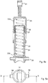
- Figs. 4 , 5a, 5b show different views of the compressible elongated device 30.
- the coil spring 33 is positioned inside the first housing 34.
- the leaf spring 37 is positioned outside the first housing, pressing outwardly onto the friction element 36, which is then pressed towards the second housing 35, thereby causing a friction force counteracting the movement of the second housing in relation to the first housing.
- the friction element 36 is arranged radially outside the coil spring 33.
- the friction element encloses a part of the coil spring 33, i.e. the friction element 36 surrounds the coil spring 33 at a part of the coils spring in its longitudinal direction.
- the friction element 36 encloses different parts of the coil spring depending on how compressed the coil spring 33 is.
- the second housing 35 encloses a part of the first housing 34.
- the second housing 35 encloses a larger part of the first housing 34 the more compressed the coil spring 33 is.
- the second housing 35 encloses a first part of the coil spring 33.
- the first housing 34 encloses a second part of the coil spring 33.
- the first part of the coil spring 33 extends from a first end 33a of the coil spring attached to the second housing 35.
- the second part of the coil spring 33 extends from a second end 33b of the coil spring attached to the first housing 34.
- the friction element 36 is positioned between the first and second housing 34, 35 and encloses the coil spring 33 so that the friction force the friction element 36 exerts onto the first and second housing 34, 35 is approximately constant, i.e. independent, on how compressed the coil spring 33 is.
- Fig. 6 shows an embodiment of the pedal system when the pedal arm 10 is in a first resting position, i.e. when there is no force applied to the foot pedal 12.
- the pedal system comprises a sensor carrier 51 that carries a rotatable part of the position sensor.
- the position sensor comprises a rotatable part that follows the movement of the pedal arm and a static part that does not follow the movement of the arm.
- the position sensor detects the position of the rotatable part in relation to the static part.
- the rotatable part may be a magnet and the static part may comprise electronics that performs the position detection by detecting the position of the magnet in relation to itself.
- Fig. 7 shows the pedal system when the pedal arm 10 is in a second position where the foot pedal 12 is pressed down. In fig.
- Fig. 7 illustrates that the angle ⁇ between the first position and the second position for the pedal arm is the same also between the first position and the second position of the position sensor as well as the first and the second position of the first end 31 of the elongated device 30.
- the sensor carrier 51 is rotatable around the pivot shaft 15 and follows the movement of the pedal arm, the position of the pedal arm is correctly detected by the sensor, and its position can be sent to a control system to control the vehicle in accordance with the position of the pedal arm.
Landscapes
- Engineering & Computer Science (AREA)
- Physics & Mathematics (AREA)
- General Physics & Mathematics (AREA)
- Automation & Control Theory (AREA)
- Chemical & Material Sciences (AREA)
- Combustion & Propulsion (AREA)
- Transportation (AREA)
- Mechanical Engineering (AREA)
- Mechanical Control Devices (AREA)
Abstract
Description
- The invention considers a pedal feel simulating system for a motor vehicle.
- Historically, motor vehicles such as cars had a purely mechanical pedal system for brakes, clutches and accelerator pedals. In such mechanical pedal systems, a pedal such as the clutch pedal was mechanically coupled to the gear box and to a coupling between the motor and the driving of the wheels so that when the driver pressed the clutch pedal, the gears of the gear box were disconnected and the motor was disconnected from the driving of the wheels via the mechanical coupling. Nowadays, car manufacturers are moving from mechanical pedal systems to electrical pedal systems. In electrical pedal systems, the car is controlled from a computer controlled system, actuated from the pedals in the car maneuvering different sensors. For example, the clutch system may be controlled depending on the position of the clutch pedal in relation to a position sensor, which position sensor sends signals to the computer controlled system, which in turn controls the gear box connection and the connection of the motor to the driving. In the electrical pedal systems, there is a need to simulate for the driver a purely mechanical pedal system so that the driver perceives that when he/she e.g. depresses the clutch pedal, the clutch system behaves as he/she is used to. This is important so that the driver feels comfortable behind the steering wheel.
- It is an object of the invention to address at least some of the problems and issues outlined above. It is possible to achieve these objects and others by using a method and an apparatus as defined in the attached independent claims.
- According to an aspect of the invention, a pedal feel simulating system for a motor vehicle is provided. The system comprises a bracket, a pedal arm pivotally coupled to the bracket at a pivot point; and a compressible elongated device for dampening a pivotal movement of the pedal arm around the pivot point. The elongated device has a longitudinal extension between a first end part coupled to the pedal arm and a second end part coupled to the bracket. The elongated device comprises a first spring parallel to the longitudinal extension of the elongated device, a first housing, and a second housing at least partly enclosing the first housing and partly enclosing the first spring. Either the first housing or the second housing is connected to the pedal arm and the one of the first housing and the second housing not being connected to the pedal arm is connected to the bracket. The elongated device further comprises a friction element arranged between the first housing and the second housing so as to enable an inertia in the pivotal movement of the pedal arm. Further, the first housing at least partly encloses the first spring and the
friction element 36 partly encloses thefirst spring 33. - That the first spring is parallel to the longitudinal extension of the elongated device may signify that the first spring has an elongated extension direction parallel to the longitudinal extension direction of the elongated device, e.g. that the first spring is compressible in a direction parallel to the longitudinal extension of the elongated device. The first spring may be a coil spring. Alternatively, the first spring may be any other type of spring, such as a gas spring or a bungee. By such an arrangement, a cost-effective pedal feel simulating system is achieved that simulates the inertia that a driver experiences when pressing a pedal arm in a purely mechanically controlled pedal system, thanks to the friction element arranged between the first and the second housing. Thereby, the driver, when depressing and releasing the pedal arm, would experience that the pedal arm behaves as it would if the pedal system would have been a purely mechanical system. Further, by arranging the friction element so that it partly encloses the first spring, at the same time as the first housing as well as the second housing, between which the friction element is positioned, both at least partly enclose the first spring, the friction element will be positioned along the first spring, between the first and second housing, in such a way that the force the friction element exerts onto the first and second housing is independent of how much the first spring is compressed. Consequently, the counter force exerted by the friction element onto the pedal arm when depressing and releasing the pedal can be approximately constant over the pedal stroke. Hereby, a pedal feel is achieved having a hysteresis that is requested by some car manufacturers. The pedal system may be a clutch system. Alternatively, the pedal system may be a brake system or an accelerator system. The pivot point may be a pivot shaft.
- According to an embodiment, the pedal system further comprises a position sensor for sensing a position of the pedal arm, the sensor being connected to a control system arranged for controlling a drive of the vehicle. By such a position sensor, the pedal system would send indications to the control system that controls the drive, e.g. drive train of the vehicle. The sensor may be electrically connected to the control system so that it sends electrical impulses to the control system. In case the pedal is a clutch pedal, the control system may in its turn control a connection between the clutch mechanism, the motor, the driving of the wheels and the gear box, in dependence of the signals from the sensor.
- According to another embodiment, the elongated device further comprises a pressing device, positioned between the first housing and the friction element for radially pressing the friction element towards the second housing or positioned between the second housing and the friction element for radially pressing the friction element towards the first housing. By such a pressing device the friction element is pressed towards the first or second housing. Thereby the friction element may be positioned well. Also, the frictional force between the friction element and the first/second housing can be selected to an appropriate level by a selection of the force of the pressing device. Also, the pressing device makes the elongated device, and consequently the pedal system, more insensitive to wear and temperature change, since force changes are counteracted by the pressing device. The radial pressing device may either be arranged for pressing the friction element outwards, i.e. towards the second housing or to press the friction element inwards, i.e. towards the first housing. According to an embodiment, the pressing device is a leaf spring.
- According to another embodiment, the friction element is positioned in a recess of the first housing or in a recess of the second housing. Thereby, the friction element is kept in position to the first/second housing and does not risk to follow the movement of the other housing opposite the housing having the recess. According to an embodiment, the friction element has a radial extension in relation to the longitudinal extension of the elongated device that is longer than the depth of the recess of the first/second housing. In other embodiments, the friction element may be connected to the first/second housing in any other possible way.
- According to an embodiment the first spring is a coil spring.
- According to an embodiment, the first end part of the elongated device is coupled to the pedal arm at a position between the pivot point and an end of the pedal arm where a driver of the vehicle is to press the pedal arm.
- According to another embodiment, the compressible elongated device is coupled to the pedal arm and to the bracket in such a way that when the pedal arm is moved around the pivot point, the longitudinal direction of the first spring is varied which results in a varying spring force component directed towards the pivot point. In one alternative, the spring force component directed towards the pivot point is higher the more the pedal is pressed in order to compensate for the increasing force from the spring, the more the spring is depressed.
- Further possible features and benefits of this solution will become apparent from the detailed description below.
- The solution will now be described in more detail by means of exemplary embodiments and with reference to the accompanying drawings, in which:
-
Fig. 1 is a perspective view of a pedal feel simulating system according to an embodiment of the invention. -
Fig. 2 is another perspective view of the system offig. 1 where parts of the elongate member have been removed to show the inside of the elongate member. -
Fig. 3 is a perspective close-up view of the elongate member of the system offig. 1 . -
Fig. 4 is an exploded view of the elongate member offig. 1 . -
Fig. 5a is a top view of the elongate member. -
Fig. 5b is a cross-sectional view of the elongate member along section X-X infig. 5a . -
Fig. 6 is a side view of an embodiment of a pedal feel simulating system, when the pedal arm is in a first resting position. -
Fig. 7 is a side view of the system offig. 6 when the pedal arm is in a second depressed position. - Briefly described, a pedal feel simulating system is provided that gives a cost-efficient solution for simulating, in an electrically controlled pedal system, the feel of a mechanical/hydraulic pedal system to a driver pressing the pedal of the electrically controlled pedal system. This is achieved by attaching a compressible elongated device between a pedal arm and a bracket/chassis of the motor vehicle so that the compressible device can be compressed when the driver presses the pedal arm. The compressible elongated device has a spring that provides a counter force to the force provided by the driver when pressing the pedal arm. Further, there is a friction element arranged between a first housing and a second housing of the compressible elongated device, which counteracts the compressing and de-compressing movement of the elongated device due to a frictional force that the friction element provides when the first and second housing moves in relation to each other in the direction of the elongated device. The friction element provides a hysteresis to the movement of the pedal up and down in relation to the force that the driver exerts to the pedal, which is similar to the hysteresis that a driver experiences in a purely mechanical/hydraulic pedal system.
-
Fig. 1 shows a pedal system 1 according to an embodiment. The pedal system 1 comprises apedal arm 10 pivotally connected via apivot point 15 to abracket 20 of a motor vehicle. As may be seen clearer infigs. 6 and7 , thepivot point 15 is realized as a pivot shaft on which a first end of thepedal arm 10 is pivotally connected to thebracket 20. Thepedal arm 10 has, at its second end distal to the first end, afoot pedal 12 onto which a driver of the vehicle is to press when maneuvering the pedal arm. Further, there is ashaft 11 connected to thepedal arm 10, between the first end and the second end of the pedal arm. The pedal system further comprises a compressibleelongated device 30, e.g. a compressible cylinder, attached with afirst end 31 to theshaft 11. Asecond end 32 of the compressibleelongated device 30 distal to thefirst end 31 is connected to thebracket 20. Theelongated device 30 further comprises a firstcylindrical housing 34 and a secondcylindrical housing 35. Thesecond housing 35 is firmly connected to thefirst end 31 of the elongated device. Thefirst housing 34 is firmly connected to thesecond end 32 of the elongated device. The first and the second housing are co-axial with each other and with the elongated extension of theelongated device 30. Thesecond housing 35 has a larger cross-sectional diameter than thefirst housing 34. The second housing is arranged to move axially in relation to the first housing depending on the pressure exerted on the pedal arm so as to surround more of the first housing the more the compressible elongated device is compressed. In an alternative embodiment that is not shown in the figures, the first housing has a larger cross-sectional diameter than the second housing and consequently surrounds more of the second housing the more thedevice 30 is compressed. - The pedal system 1 further comprises a position sensor for sensing a position of the
pedal arm 10. Infig. 1 ,reference 50 points to a contact to which the position sensor is electrically connected. The actual position sensor is hidden in the figure. Thecontact 50 is arranged to receive an electrical cable that with its other end is to be connected to a control system arranged for controlling a drive of the vehicle so that positions sensed by the position sensor can be sent to the control system to control the vehicle drive accordingly. -
Fig. 2 shows the pedal system where parts of thefirst housing 34 and thesecond housing 35 of the compressibleelongated device 30 has been taken away to reveal the inside of theelongated device 30. Consequently, acoil spring 33 arranged inside the elongated device is shown, as well as afriction element 36 arranged between the first and the second housing. Further, infig. 2 , theelongated device 30 comprises aprotrusion 39 arranged at itssecond end 32. Theprotrusion 39 is arranged to be positioned in a receiving means 21 of the bracket so as to keep the elongated device in position to the bracket. As could be seen infig. 5a there are twoprotrusions 39 arranged at opposite sides of the elongated device, each protrusion being arranged to be positioned in a receiving means 21 of the bracket. -
Fig. 3 is a close-up view of the compressibleelongated device 30 where parts of thefirst housing 34 and thesecond housing 35 has been taken away to reveal the inside of thedevice 30. Theelongated device 30 further comprises aleaf spring 37 positioned between thefirst housing 34 and thefriction element 36 for radially pressing thefriction element 36 towards thesecond housing 35. -
Figs. 4 ,5a, 5b show different views of the compressibleelongated device 30. Thecoil spring 33 is positioned inside thefirst housing 34. Theleaf spring 37 is positioned outside the first housing, pressing outwardly onto thefriction element 36, which is then pressed towards thesecond housing 35, thereby causing a friction force counteracting the movement of the second housing in relation to the first housing. As seen infig. 5b , thefriction element 36 is arranged radially outside thecoil spring 33. The friction element encloses a part of thecoil spring 33, i.e. thefriction element 36 surrounds thecoil spring 33 at a part of the coils spring in its longitudinal direction. Thefriction element 36 encloses different parts of the coil spring depending on how compressed thecoil spring 33 is. Thesecond housing 35 encloses a part of thefirst housing 34. Thesecond housing 35 encloses a larger part of thefirst housing 34 the more compressed thecoil spring 33 is. Thesecond housing 35 encloses a first part of thecoil spring 33. Thefirst housing 34 encloses a second part of thecoil spring 33. The first part of thecoil spring 33 extends from afirst end 33a of the coil spring attached to thesecond housing 35. The second part of thecoil spring 33 extends from asecond end 33b of the coil spring attached to thefirst housing 34. Thefriction element 36 is positioned between the first andsecond housing coil spring 33 so that the friction force thefriction element 36 exerts onto the first andsecond housing coil spring 33 is. -
Fig. 6 shows an embodiment of the pedal system when thepedal arm 10 is in a first resting position, i.e. when there is no force applied to thefoot pedal 12. The pedal system comprises asensor carrier 51 that carries a rotatable part of the position sensor. The position sensor comprises a rotatable part that follows the movement of the pedal arm and a static part that does not follow the movement of the arm. The position sensor detects the position of the rotatable part in relation to the static part. The rotatable part may be a magnet and the static part may comprise electronics that performs the position detection by detecting the position of the magnet in relation to itself.Fig. 7 shows the pedal system when thepedal arm 10 is in a second position where thefoot pedal 12 is pressed down. Infig. 7 also the first position is indicated. Thefoot pedal 12 in the first position has been givenreference number 121, whereas the foot pedal in the second position has been givenreference number 122.Fig. 7 illustrates that the angle α between the first position and the second position for the pedal arm is the same also between the first position and the second position of the position sensor as well as the first and the second position of thefirst end 31 of theelongated device 30. As thesensor carrier 51 is rotatable around thepivot shaft 15 and follows the movement of the pedal arm, the position of the pedal arm is correctly detected by the sensor, and its position can be sent to a control system to control the vehicle in accordance with the position of the pedal arm. - Although the description above contains a plurality of specificities, these should not be construed as limiting the scope of the concept described herein but as merely providing illustrations of some exemplifying embodiments of the described concept. It will be appreciated that the scope of the presently described concept fully encompasses other embodiments which may become obvious to those skilled in the art, and that the scope of the presently described concept is accordingly not to be limited. Reference to an element in the singular is not intended to mean "one and only one" unless explicitly so stated, but rather "one or more." All structural and functional equivalents to the elements of the above-described embodiments that are known to those of ordinary skill in the art are expressly incorporated herein and are intended to be encompassed hereby.
Claims (9)
- A pedal feel simulating system (1) for a motor vehicle, the system comprising:a bracket (20),a pedal arm (10) pivotally coupled to the bracket (20) at a pivot point (15);a compressible elongated device (30) for dampening a pivotal movement of the pedal arm around the pivot point (15), the elongated device having a longitudinal extension between a first end part (31) coupled to the pedal arm (10) and a second end part (32) coupled to the bracket (20), characterized in that the elongated device comprises:a first spring (33) parallel to the longitudinal extension of the elongated device (30);a first housing (34) at least partly enclosing the first spring (33);a second housing (35) at least partly enclosing the first housing (34) and partly enclosing the first spring (33), wherein either the first housing (34) or the second housing (35) is connected to the pedal arm (10) and the one of the first housing and the second housing not being connected to the pedal arm is connected to the bracket (20),a friction element (36) arranged between the first housing (34) and the second housing (35) so as to enable an inertia in the pivotal movement of the pedal arm, wherein the friction element (36) partly encloses the first spring (33).
- Pedal system according to claim 1, further comprising a position sensor for sensing a position of the pedal arm (10), the sensor being connected to a control system arranged for controlling a drive of the vehicle.
- Pedal system according to claim 1 or 2, wherein the elongated device (30) further comprises:a pressing device (37), positioned between the first housing (34) and the friction element (36) for radially pressing the friction element towards the second housing (35) or positioned between the second housing (35) and the friction element (36) for radially pressing the friction element towards the first housing (34).
- Pedal system according to claim 3, wherein the pressing device (37) is a leaf spring.
- Pedal system according to any of the preceding claims, wherein the friction element (36) is positioned in a recess of the first housing or in a recess of the second housing.
- Pedal system according to any of the preceding claims, wherein the first spring (33) is a coil spring.
- Pedal system according to any of the preceding claims, wherein the first end part (31) of the elongated device (30) is coupled to the pedal arm (10) at a position between the pivot point (15) and an end (12) of the pedal arm (10) where a driver of the vehicle is to press the pedal arm.
- Pedal system according to any of the preceding claims, wherein the compressible elongated device (30) is coupled to the pedal arm (10) and to the bracket (20) in such a way that when the pedal arm is moved around the pivot point (15), the longitudinal direction of the first spring (33) is varied which results in a varying spring force component directed towards the pivot point (15).
- Pedal system according to claim 8, wherein the longitudinal direction of the first spring (33) is varied when the pedal arm (10) is moved around the pivot point (15) in such a way that the spring force component directed towards the pivot point is higher the more a pedal of the pedal arm is pressed in order to compensate for an increasing force from the first spring, the more the first spring is depressed.
Applications Claiming Priority (1)
| Application Number | Priority Date | Filing Date | Title |
|---|---|---|---|
| SE1650657A SE540815C2 (en) | 2016-05-17 | 2016-05-17 | A pedal feel simulating system for a motor vehicle |
Publications (3)
| Publication Number | Publication Date |
|---|---|
| EP3264218A2 true EP3264218A2 (en) | 2018-01-03 |
| EP3264218A3 EP3264218A3 (en) | 2018-07-25 |
| EP3264218B1 EP3264218B1 (en) | 2020-05-27 |
Family
ID=58709289
Family Applications (1)
| Application Number | Title | Priority Date | Filing Date |
|---|---|---|---|
| EP17170783.9A Active EP3264218B1 (en) | 2016-05-17 | 2017-05-12 | A pedal feel simulating system for a motor vehicle |
Country Status (2)
| Country | Link |
|---|---|
| EP (1) | EP3264218B1 (en) |
| SE (1) | SE540815C2 (en) |
Cited By (2)
| Publication number | Priority date | Publication date | Assignee | Title |
|---|---|---|---|---|
| CN110316682A (en) * | 2019-07-23 | 2019-10-11 | 安徽合力股份有限公司 | A kind of diesel fork lift truck electronics inching gear |
| CN114701456A (en) * | 2022-04-02 | 2022-07-05 | 武汉理工大学 | Adjustable brake-by-wire pedal simulator |
Families Citing this family (1)
| Publication number | Priority date | Publication date | Assignee | Title |
|---|---|---|---|---|
| CN116472208A (en) | 2020-12-22 | 2023-07-21 | Cj汽车制造公司 | Brake pedal system for motor vehicles |
Family Cites Families (3)
| Publication number | Priority date | Publication date | Assignee | Title |
|---|---|---|---|---|
| DE3412318A1 (en) * | 1984-04-03 | 1985-10-10 | Westfälische Metall Industrie KG Hueck & Co, 4780 Lippstadt | Reference element of a device for adjusting the speed of travel of a vehicle |
| JP4724340B2 (en) * | 1999-09-14 | 2011-07-13 | 株式会社ミクニ | Accelerator pedal device |
| US6360631B1 (en) * | 2000-01-12 | 2002-03-26 | Dura Global Technologies, Inc. | Electronic throttle control accelerator pedal mechanism with mechanical hysteresis provider |
-
2016
- 2016-05-17 SE SE1650657A patent/SE540815C2/en not_active IP Right Cessation
-
2017
- 2017-05-12 EP EP17170783.9A patent/EP3264218B1/en active Active
Non-Patent Citations (1)
| Title |
|---|
| None |
Cited By (2)
| Publication number | Priority date | Publication date | Assignee | Title |
|---|---|---|---|---|
| CN110316682A (en) * | 2019-07-23 | 2019-10-11 | 安徽合力股份有限公司 | A kind of diesel fork lift truck electronics inching gear |
| CN114701456A (en) * | 2022-04-02 | 2022-07-05 | 武汉理工大学 | Adjustable brake-by-wire pedal simulator |
Also Published As
| Publication number | Publication date |
|---|---|
| SE1650657A1 (en) | 2017-11-18 |
| EP3264218A3 (en) | 2018-07-25 |
| EP3264218B1 (en) | 2020-05-27 |
| SE540815C2 (en) | 2018-11-20 |
Similar Documents
| Publication | Publication Date | Title |
|---|---|---|
| EP3589518B1 (en) | Pedal emulator for a motor vehicle | |
| US7216563B2 (en) | Electronic throttle control with hysteresis device | |
| US8635930B2 (en) | Floor mounted pedal with position sensor | |
| US20070234842A1 (en) | Electronic throttle control with hysteresis and kickdown | |
| EP4222029B1 (en) | Brake pedal system for a motor vehicle | |
| US10112587B2 (en) | Electronic braking system | |
| US8650984B2 (en) | Electronic clutch pedal assembly having varying resistance | |
| US20130047776A1 (en) | Drive pedal unit for motor vehicles | |
| EP3264218B1 (en) | A pedal feel simulating system for a motor vehicle | |
| JP5646655B2 (en) | Vehicle control system | |
| US11560127B2 (en) | Device for a brake pedal force-travel emulator with force and displacement sensor and corresponding process | |
| JP2005263074A (en) | Brake device for vehicle | |
| US12346145B2 (en) | Passive pedal force emulator having coil springs | |
| CN118838472A (en) | Pedal unit for controlling vehicle functions | |
| US20110126642A1 (en) | Adapter for turning a steering wheel | |
| KR20180018125A (en) | Variable limiting apparatus of steering wheel rotation angle | |
| US20040144195A1 (en) | Brake control device on steering wheel | |
| EP4722055A1 (en) | Pedal pad device for a motor vehicle and motor vehicle | |
| US20260079522A1 (en) | Pedal device for a vehicle, and a vehicle | |
| WO2024256948A1 (en) | Braking system | |
| CN118915880A (en) | Pedal unit for controlling vehicle functions | |
| CA2478045A1 (en) | Brake control device on steering wheel | |
| HK1076140B (en) | Electronic throttle control with hysteresis device | |
| JP2008179354A (en) | Brake device |
Legal Events
| Date | Code | Title | Description |
|---|---|---|---|
| PUAI | Public reference made under article 153(3) epc to a published international application that has entered the european phase |
Free format text: ORIGINAL CODE: 0009012 |
|
| STAA | Information on the status of an ep patent application or granted ep patent |
Free format text: STATUS: THE APPLICATION HAS BEEN PUBLISHED |
|
| AK | Designated contracting states |
Kind code of ref document: A2 Designated state(s): AL AT BE BG CH CY CZ DE DK EE ES FI FR GB GR HR HU IE IS IT LI LT LU LV MC MK MT NL NO PL PT RO RS SE SI SK SM TR |
|
| AX | Request for extension of the european patent |
Extension state: BA ME |
|
| PUAL | Search report despatched |
Free format text: ORIGINAL CODE: 0009013 |
|
| AK | Designated contracting states |
Kind code of ref document: A3 Designated state(s): AL AT BE BG CH CY CZ DE DK EE ES FI FR GB GR HR HU IE IS IT LI LT LU LV MC MK MT NL NO PL PT RO RS SE SI SK SM TR |
|
| AX | Request for extension of the european patent |
Extension state: BA ME |
|
| RIC1 | Information provided on ipc code assigned before grant |
Ipc: G05G 1/44 20080401ALI20180615BHEP Ipc: G05G 5/03 20080401ALI20180615BHEP Ipc: G05G 5/05 20060101AFI20180615BHEP |
|
| STAA | Information on the status of an ep patent application or granted ep patent |
Free format text: STATUS: REQUEST FOR EXAMINATION WAS MADE |
|
| RIC1 | Information provided on ipc code assigned before grant |
Ipc: G05G 5/05 20060101AFI20180615BHEP Ipc: G05G 5/03 20080401ALI20180615BHEP Ipc: G05G 1/44 20080401ALI20180615BHEP |
|
| 17P | Request for examination filed |
Effective date: 20190114 |
|
| RBV | Designated contracting states (corrected) |
Designated state(s): AL AT BE BG CH CY CZ DE DK EE ES FI FR GB GR HR HU IE IS IT LI LT LU LV MC MK MT NL NO PL PT RO RS SE SI SK SM TR |
|
| GRAP | Despatch of communication of intention to grant a patent |
Free format text: ORIGINAL CODE: EPIDOSNIGR1 |
|
| STAA | Information on the status of an ep patent application or granted ep patent |
Free format text: STATUS: GRANT OF PATENT IS INTENDED |
|
| INTG | Intention to grant announced |
Effective date: 20200108 |
|
| GRAS | Grant fee paid |
Free format text: ORIGINAL CODE: EPIDOSNIGR3 |
|
| GRAA | (expected) grant |
Free format text: ORIGINAL CODE: 0009210 |
|
| STAA | Information on the status of an ep patent application or granted ep patent |
Free format text: STATUS: THE PATENT HAS BEEN GRANTED |
|
| AK | Designated contracting states |
Kind code of ref document: B1 Designated state(s): AL AT BE BG CH CY CZ DE DK EE ES FI FR GB GR HR HU IE IS IT LI LT LU LV MC MK MT NL NO PL PT RO RS SE SI SK SM TR |
|
| REG | Reference to a national code |
Ref country code: GB Ref legal event code: FG4D |
|
| REG | Reference to a national code |
Ref country code: CH Ref legal event code: EP |
|
| REG | Reference to a national code |
Ref country code: AT Ref legal event code: REF Ref document number: 1275209 Country of ref document: AT Kind code of ref document: T Effective date: 20200615 |
|
| REG | Reference to a national code |
Ref country code: DE Ref legal event code: R096 Ref document number: 602017017177 Country of ref document: DE |
|
| REG | Reference to a national code |
Ref country code: LT Ref legal event code: MG4D |
|
| PG25 | Lapsed in a contracting state [announced via postgrant information from national office to epo] |
Ref country code: FI Free format text: LAPSE BECAUSE OF FAILURE TO SUBMIT A TRANSLATION OF THE DESCRIPTION OR TO PAY THE FEE WITHIN THE PRESCRIBED TIME-LIMIT Effective date: 20200527 Ref country code: PT Free format text: LAPSE BECAUSE OF FAILURE TO SUBMIT A TRANSLATION OF THE DESCRIPTION OR TO PAY THE FEE WITHIN THE PRESCRIBED TIME-LIMIT Effective date: 20200928 Ref country code: SE Free format text: LAPSE BECAUSE OF FAILURE TO SUBMIT A TRANSLATION OF THE DESCRIPTION OR TO PAY THE FEE WITHIN THE PRESCRIBED TIME-LIMIT Effective date: 20200527 Ref country code: IS Free format text: LAPSE BECAUSE OF FAILURE TO SUBMIT A TRANSLATION OF THE DESCRIPTION OR TO PAY THE FEE WITHIN THE PRESCRIBED TIME-LIMIT Effective date: 20200927 Ref country code: GR Free format text: LAPSE BECAUSE OF FAILURE TO SUBMIT A TRANSLATION OF THE DESCRIPTION OR TO PAY THE FEE WITHIN THE PRESCRIBED TIME-LIMIT Effective date: 20200828 Ref country code: NO Free format text: LAPSE BECAUSE OF FAILURE TO SUBMIT A TRANSLATION OF THE DESCRIPTION OR TO PAY THE FEE WITHIN THE PRESCRIBED TIME-LIMIT Effective date: 20200827 Ref country code: LT Free format text: LAPSE BECAUSE OF FAILURE TO SUBMIT A TRANSLATION OF THE DESCRIPTION OR TO PAY THE FEE WITHIN THE PRESCRIBED TIME-LIMIT Effective date: 20200527 |
|
| REG | Reference to a national code |
Ref country code: NL Ref legal event code: MP Effective date: 20200527 |
|
| PG25 | Lapsed in a contracting state [announced via postgrant information from national office to epo] |
Ref country code: BG Free format text: LAPSE BECAUSE OF FAILURE TO SUBMIT A TRANSLATION OF THE DESCRIPTION OR TO PAY THE FEE WITHIN THE PRESCRIBED TIME-LIMIT Effective date: 20200827 Ref country code: RS Free format text: LAPSE BECAUSE OF FAILURE TO SUBMIT A TRANSLATION OF THE DESCRIPTION OR TO PAY THE FEE WITHIN THE PRESCRIBED TIME-LIMIT Effective date: 20200527 Ref country code: HR Free format text: LAPSE BECAUSE OF FAILURE TO SUBMIT A TRANSLATION OF THE DESCRIPTION OR TO PAY THE FEE WITHIN THE PRESCRIBED TIME-LIMIT Effective date: 20200527 Ref country code: LV Free format text: LAPSE BECAUSE OF FAILURE TO SUBMIT A TRANSLATION OF THE DESCRIPTION OR TO PAY THE FEE WITHIN THE PRESCRIBED TIME-LIMIT Effective date: 20200527 |
|
| REG | Reference to a national code |
Ref country code: AT Ref legal event code: MK05 Ref document number: 1275209 Country of ref document: AT Kind code of ref document: T Effective date: 20200527 |
|
| PG25 | Lapsed in a contracting state [announced via postgrant information from national office to epo] |
Ref country code: NL Free format text: LAPSE BECAUSE OF FAILURE TO SUBMIT A TRANSLATION OF THE DESCRIPTION OR TO PAY THE FEE WITHIN THE PRESCRIBED TIME-LIMIT Effective date: 20200527 Ref country code: AL Free format text: LAPSE BECAUSE OF FAILURE TO SUBMIT A TRANSLATION OF THE DESCRIPTION OR TO PAY THE FEE WITHIN THE PRESCRIBED TIME-LIMIT Effective date: 20200527 |
|
| PG25 | Lapsed in a contracting state [announced via postgrant information from national office to epo] |
Ref country code: ES Free format text: LAPSE BECAUSE OF FAILURE TO SUBMIT A TRANSLATION OF THE DESCRIPTION OR TO PAY THE FEE WITHIN THE PRESCRIBED TIME-LIMIT Effective date: 20200527 Ref country code: AT Free format text: LAPSE BECAUSE OF FAILURE TO SUBMIT A TRANSLATION OF THE DESCRIPTION OR TO PAY THE FEE WITHIN THE PRESCRIBED TIME-LIMIT Effective date: 20200527 Ref country code: DK Free format text: LAPSE BECAUSE OF FAILURE TO SUBMIT A TRANSLATION OF THE DESCRIPTION OR TO PAY THE FEE WITHIN THE PRESCRIBED TIME-LIMIT Effective date: 20200527 Ref country code: IT Free format text: LAPSE BECAUSE OF FAILURE TO SUBMIT A TRANSLATION OF THE DESCRIPTION OR TO PAY THE FEE WITHIN THE PRESCRIBED TIME-LIMIT Effective date: 20200527 Ref country code: SM Free format text: LAPSE BECAUSE OF FAILURE TO SUBMIT A TRANSLATION OF THE DESCRIPTION OR TO PAY THE FEE WITHIN THE PRESCRIBED TIME-LIMIT Effective date: 20200527 Ref country code: CZ Free format text: LAPSE BECAUSE OF FAILURE TO SUBMIT A TRANSLATION OF THE DESCRIPTION OR TO PAY THE FEE WITHIN THE PRESCRIBED TIME-LIMIT Effective date: 20200527 Ref country code: EE Free format text: LAPSE BECAUSE OF FAILURE TO SUBMIT A TRANSLATION OF THE DESCRIPTION OR TO PAY THE FEE WITHIN THE PRESCRIBED TIME-LIMIT Effective date: 20200527 Ref country code: RO Free format text: LAPSE BECAUSE OF FAILURE TO SUBMIT A TRANSLATION OF THE DESCRIPTION OR TO PAY THE FEE WITHIN THE PRESCRIBED TIME-LIMIT Effective date: 20200527 |
|
| PG25 | Lapsed in a contracting state [announced via postgrant information from national office to epo] |
Ref country code: SK Free format text: LAPSE BECAUSE OF FAILURE TO SUBMIT A TRANSLATION OF THE DESCRIPTION OR TO PAY THE FEE WITHIN THE PRESCRIBED TIME-LIMIT Effective date: 20200527 Ref country code: PL Free format text: LAPSE BECAUSE OF FAILURE TO SUBMIT A TRANSLATION OF THE DESCRIPTION OR TO PAY THE FEE WITHIN THE PRESCRIBED TIME-LIMIT Effective date: 20200527 |
|
| REG | Reference to a national code |
Ref country code: DE Ref legal event code: R097 Ref document number: 602017017177 Country of ref document: DE |
|
| PLBE | No opposition filed within time limit |
Free format text: ORIGINAL CODE: 0009261 |
|
| STAA | Information on the status of an ep patent application or granted ep patent |
Free format text: STATUS: NO OPPOSITION FILED WITHIN TIME LIMIT |
|
| 26N | No opposition filed |
Effective date: 20210302 |
|
| PG25 | Lapsed in a contracting state [announced via postgrant information from national office to epo] |
Ref country code: SI Free format text: LAPSE BECAUSE OF FAILURE TO SUBMIT A TRANSLATION OF THE DESCRIPTION OR TO PAY THE FEE WITHIN THE PRESCRIBED TIME-LIMIT Effective date: 20200527 |
|
| REG | Reference to a national code |
Ref country code: CH Ref legal event code: PL |
|
| PG25 | Lapsed in a contracting state [announced via postgrant information from national office to epo] |
Ref country code: CH Free format text: LAPSE BECAUSE OF NON-PAYMENT OF DUE FEES Effective date: 20210531 Ref country code: MC Free format text: LAPSE BECAUSE OF FAILURE TO SUBMIT A TRANSLATION OF THE DESCRIPTION OR TO PAY THE FEE WITHIN THE PRESCRIBED TIME-LIMIT Effective date: 20200527 Ref country code: LU Free format text: LAPSE BECAUSE OF NON-PAYMENT OF DUE FEES Effective date: 20210512 Ref country code: LI Free format text: LAPSE BECAUSE OF NON-PAYMENT OF DUE FEES Effective date: 20210531 |
|
| REG | Reference to a national code |
Ref country code: BE Ref legal event code: MM Effective date: 20210531 |
|
| PG25 | Lapsed in a contracting state [announced via postgrant information from national office to epo] |
Ref country code: IE Free format text: LAPSE BECAUSE OF NON-PAYMENT OF DUE FEES Effective date: 20210512 |
|
| PG25 | Lapsed in a contracting state [announced via postgrant information from national office to epo] |
Ref country code: FR Free format text: LAPSE BECAUSE OF NON-PAYMENT OF DUE FEES Effective date: 20210531 |
|
| PG25 | Lapsed in a contracting state [announced via postgrant information from national office to epo] |
Ref country code: BE Free format text: LAPSE BECAUSE OF NON-PAYMENT OF DUE FEES Effective date: 20210531 |
|
| PGFP | Annual fee paid to national office [announced via postgrant information from national office to epo] |
Ref country code: GB Payment date: 20220518 Year of fee payment: 6 |
|
| PG25 | Lapsed in a contracting state [announced via postgrant information from national office to epo] |
Ref country code: HU Free format text: LAPSE BECAUSE OF FAILURE TO SUBMIT A TRANSLATION OF THE DESCRIPTION OR TO PAY THE FEE WITHIN THE PRESCRIBED TIME-LIMIT; INVALID AB INITIO Effective date: 20170512 |
|
| PG25 | Lapsed in a contracting state [announced via postgrant information from national office to epo] |
Ref country code: CY Free format text: LAPSE BECAUSE OF FAILURE TO SUBMIT A TRANSLATION OF THE DESCRIPTION OR TO PAY THE FEE WITHIN THE PRESCRIBED TIME-LIMIT Effective date: 20200527 |
|
| GBPC | Gb: european patent ceased through non-payment of renewal fee |
Effective date: 20230512 |
|
| PG25 | Lapsed in a contracting state [announced via postgrant information from national office to epo] |
Ref country code: MK Free format text: LAPSE BECAUSE OF FAILURE TO SUBMIT A TRANSLATION OF THE DESCRIPTION OR TO PAY THE FEE WITHIN THE PRESCRIBED TIME-LIMIT Effective date: 20200527 Ref country code: GB Free format text: LAPSE BECAUSE OF NON-PAYMENT OF DUE FEES Effective date: 20230512 |
|
| PG25 | Lapsed in a contracting state [announced via postgrant information from national office to epo] |
Ref country code: TR Free format text: LAPSE BECAUSE OF FAILURE TO SUBMIT A TRANSLATION OF THE DESCRIPTION OR TO PAY THE FEE WITHIN THE PRESCRIBED TIME-LIMIT Effective date: 20200527 |
|
| PG25 | Lapsed in a contracting state [announced via postgrant information from national office to epo] |
Ref country code: MT Free format text: LAPSE BECAUSE OF FAILURE TO SUBMIT A TRANSLATION OF THE DESCRIPTION OR TO PAY THE FEE WITHIN THE PRESCRIBED TIME-LIMIT Effective date: 20200527 |
|
| PGFP | Annual fee paid to national office [announced via postgrant information from national office to epo] |
Ref country code: DE Payment date: 20250520 Year of fee payment: 9 |