EP3264216A2 - Alignment device for a selector lever - Google Patents
Alignment device for a selector lever Download PDFInfo
- Publication number
- EP3264216A2 EP3264216A2 EP17168839.3A EP17168839A EP3264216A2 EP 3264216 A2 EP3264216 A2 EP 3264216A2 EP 17168839 A EP17168839 A EP 17168839A EP 3264216 A2 EP3264216 A2 EP 3264216A2
- Authority
- EP
- European Patent Office
- Prior art keywords
- detent
- shaft
- selector lever
- magnet
- detent pin
- Prior art date
- Legal status (The legal status is an assumption and is not a legal conclusion. Google has not performed a legal analysis and makes no representation as to the accuracy of the status listed.)
- Granted
Links
Images


Classifications
-
- B—PERFORMING OPERATIONS; TRANSPORTING
- B64—AIRCRAFT; AVIATION; COSMONAUTICS
- B64C—AEROPLANES; HELICOPTERS
- B64C13/00—Control systems or transmitting systems for actuating flying-control surfaces, lift-increasing flaps, air brakes, or spoilers
- B64C13/02—Initiating means
- B64C13/04—Initiating means actuated personally
- B64C13/042—Initiating means actuated personally operated by hand
- B64C13/0425—Initiating means actuated personally operated by hand for actuating trailing or leading edge flaps, air brakes or spoilers
-
- B—PERFORMING OPERATIONS; TRANSPORTING
- B64—AIRCRAFT; AVIATION; COSMONAUTICS
- B64C—AEROPLANES; HELICOPTERS
- B64C13/00—Control systems or transmitting systems for actuating flying-control surfaces, lift-increasing flaps, air brakes, or spoilers
- B64C13/02—Initiating means
- B64C13/04—Initiating means actuated personally
- B64C13/042—Initiating means actuated personally operated by hand
- B64C13/0421—Initiating means actuated personally operated by hand control sticks for primary flight controls
-
- G—PHYSICS
- G05—CONTROLLING; REGULATING
- G05G—CONTROL DEVICES OR SYSTEMS INSOFAR AS CHARACTERISED BY MECHANICAL FEATURES ONLY
- G05G1/00—Controlling members, e.g. knobs or handles; Assemblies or arrangements thereof; Indicating position of controlling members
- G05G1/04—Controlling members for hand actuation by pivoting movement, e.g. levers
-
- G—PHYSICS
- G05—CONTROLLING; REGULATING
- G05G—CONTROL DEVICES OR SYSTEMS INSOFAR AS CHARACTERISED BY MECHANICAL FEATURES ONLY
- G05G5/00—Means for preventing, limiting or returning the movements of parts of a control mechanism, e.g. locking controlling member
- G05G5/06—Means for preventing, limiting or returning the movements of parts of a control mechanism, e.g. locking controlling member for holding members in one or a limited number of definite positions only
-
- G—PHYSICS
- G05—CONTROLLING; REGULATING
- G05G—CONTROL DEVICES OR SYSTEMS INSOFAR AS CHARACTERISED BY MECHANICAL FEATURES ONLY
- G05G5/00—Means for preventing, limiting or returning the movements of parts of a control mechanism, e.g. locking controlling member
- G05G5/03—Means for enhancing the operator's awareness of arrival of the controlling member at a command or datum position; Providing feel, e.g. means for creating a counterforce
Definitions
- the present disclosure relates generally to selector levers and, more particularly, to an alignment device for assisting in aligning a selector lever that may be found, for example, in the cockpit of an aircraft.
- Conventional aircraft are commonly equipped with a selector lever for manually controlling the actuation of high-lift surfaces such as flaps, ailerons, or other moveable features of the aircraft.
- the selector lever is mounted in the cockpit for the pilot to select the desired equipment configuration by moving the lever to a desired position. For instance, if flaps are controlled by the selector lever, the flaps may be positioned in multiple positions corresponding to take off from a standard runway, short runway, landing, etc.
- the conventional selector lever is typically constructed with a shaft rotatably arranged adjacent one or two detent plates. When the lever is rotated in a desired position for controlling the associated moveable feature, a respective detent pin is positioned within a corresponding detent slot for securing the lever into position.
- Alignment of the detent pin within a corresponding detent slot is necessary in order to properly secure the selector lever in the desired position.
- the selector lever being operated in a linear movement between a forward and rear position while rotating about a central axis, aligning the detent pin within a corresponding detent slot is difficult. Accordingly, there is a need to assist the operator in properly locating the selector lever in position where the detent pin may accurately be positioned within the desired detent slot.
- a selector lever in one embodiment includes a shaft in pivotal communication with a housing and a detent arrangement in operable communication with the shaft and the housing configured to maintain the shaft in a selected position when engaged and to allow the shaft to rotate when disengaged.
- a magnetic detent pin alignment mechanism is configured to generate magnetic forces indicative of alignment of the shaft in selectable position.
- a system for manipulating a high-lift surface of an aircraft into a plurality of predetermined operative conditions includes a selector lever having a shaft having a proximal end rotatably attached to a pivot.
- the pivot is disposed within housing and the shaft has a distal end projecting above the housing.
- a magnet is carried by the shaft.
- a slide is arranged to be movable along the shaft.
- a detent pin is operatively connected to the slide.
- a detent plate is disposed in the housing and has a plurality of detent slots separated by spacers for receiving the detent pin.
- a magnetic detent pin aligning mechanism communicates with the magnet carried by the shaft to provide feedback regarding a position of the detent pin with respect to one of the detent slots of the detent plate for assisting in positioning the selector lever for aligning the detent pin with respect to one of the slots of the detent plate.
- a method of actuating a selector lever includes disengaging a detent arrangement that when engaged maintains the selector lever in a selected position, rotating the selector lever, allowing magnetic forces in a magnetic detent pin aligning mechanism to assist in aligning the selector lever in one of a plurality of selectable positions and engaging the detent arrangement.
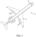
- Fig. 1 shows a top view of an aircraft 1 having an aircraft actuator system that employs the selector lever of the present disclosure.
- the selector lever is contemplated to be employed in connection with one or more of the high-lift surfaces associated with an aircraft.
- the selector lever of the aircraft actuator system may be used to control the position of a plurality of flaps 2 located on the wings 3 of the aircraft 1.
- the selector lever enables the operator (or pilot) to accurately control the position of the flaps 2 from the cockpit 4.
- the selector lever may find other uses, in differing environments, without departing from the scope of the present disclosure.
- Fig. 2A is partial cross-sectional side view of a hand-operated selector lever 5 according to one embodiment of the present disclosure.
- the selector lever 5 includes a shaft 6 having a proximal end 20 that is rotatably attached to a pivot 7 that is disposed in a housing 8.
- the shaft 6 also comprises a distal end 9 that projects beyond the housing 8.
- a slide 10 is arranged to move along the shaft 6 along the portion which projects beyond housing 8.
- Fig. 2A shows a detent plate 11 with a plurality of detent slots 12 disposed in the housing 8 parallel to the path of the pivoting shaft 6.
- Fig. 2A further shows a detent pin 13 arranged on the shaft 6 to engage the first plurality of detent slots 12 of the detent plate 11.
- the configuration of the detent slots 12 of detent plate 11 defines a detent arrangement.
- the detent pin 13 is operatively connected to the slide 10 such that translational movement of the slide 10 along the shaft results in movement of the detent pin 13.
- a set of attraction magnets 17 are attached to the detent plate 11 at multiple locations along a radial arc relative to the pivot 7.
- Each of the attraction magnets 17 are oriented in radial alignment relative to one of the detent slots 12 to generate magnetic interaction with a shaft magnet 18 as detailed below.
- Fig. 2B shows a cross-sectional view of the selector lever 5.
- a magnetic detent pin aligning mechanism 14 includes attraction magnet 17a from the set of attraction magnets 17 attached to the detent plate 11 and the shaft magnet 18 carried by the shaft 6.
- Attraction magnet 17a has a pole generating a magnetic field and the shaft magnet 18 has a pole generating a magnetic field.
- attraction magnet 17a has a north pole facing towards the shaft and shaft magnet 18 has a south pole outwardly facing towards the detent plate.
- Fig. 3A is partial cross-section side view of a hand-operated selector lever 5 according to a second embodiment of the present disclosure.
- the selector lever 5 includes a shaft 6 having a proximal end that is rotatably attached to a pivot 7 that is disposed in a housing 8.
- the shaft 6 also comprises a distal end 9 that projects beyond housing 8.
- a slide 10 is arranged to move along the portion of shaft 6 which extends beyond housing 8.
- Fig. 3A shows a detent plate 11 with a plurality of detent slots 12 disposed in the housing 8 parallel to the path of the pivoting shaft 6.
- a plurality of spacers 15 separates the respective detent slots 12.
- 3A further shows a detent pin 13 arranged on the shaft 6 to engage the first plurality of slots 12 of the detent plate 11.
- the detent pin 13 is operatively connected to the slide 10 such that translational movement of the slide 10 along the shaft results in movement of the detent pin 13.
- a set of repulsion magnets 19 are carried by detent plate 11 at multiple locations in radial alignment with respective slot spacers 15.
- a magnetic detent pin aligning mechanism 14 includes a repulsion magnet 19a from the set of repulsion magnets 19 carried by detent plate 11 and a shaft magnet 18 carried by shaft 6.
- Repulsion magnet 19a has a pole generating a magnetic field and shaft magnet 18 has a pole generating a magnetic field.
- repulsion magnet 19a has a north pole facing towards the shaft and shaft magnet 18 has a north pole outwardly facing towards the detent plate.
- Fig. 4A is a partial cross-sectional side view of a hand-operated selector lever 5 according to a third embodiment of the present disclosure.
- the selector lever 5 includes a shaft 6 having a proximal end that is rotatably attached to a pivot 7 that is disposed in a housing 8.
- the shaft 6 also comprises a distal end 9 that projects above housing 8.
- a slide 10 is arranged to move along the portion of the shaft 6 which projects above the housing 8.
- a detent plate 11 with a plurality of detent slots 12 is disposed in the housing 8 parallel to the path of the pivoting shaft 6.
- a detent pin 13 arranged on the shaft 6 to engage the first plurality of detent slots 12 of the detent plate 11.
- the detent pin 13 is operatively connected to the slide 10 such that translational movement of the slide 10 along the shaft results in movement of the detent pin 13.
- a set of attraction magnets 17 are attached to the detent plate 11 at multiple locations radially aligned with respective detent slots 12 and a set of repulsive magnets 19 are carried by detent plate 11 at multiple locations radially aligned with respective slot spacers 15 which are not receptive of receiving a detent pin.
- alignment device 14 includes both set of attraction magnets 17 and set of repulsion magnets 19 carried by detent plate 11 and a shaft magnet 18 carried by shaft 6 (not shown).
- the attraction magnets 17 and shaft magnet 18 have oppositely facing poles.
- the repulsion magnets 19 and shaft magnet 18 have similarly facing poles.
- a respective of the set of repulsion magnets 19 will repel shaft magnet 18 due to the same polarity of the respective magnets thereby providing feedback urging the lever to continue in a lateral movement either forward or aft of the respective slot spacer 15.
- a respective of the attraction magnets 17 will attract shaft magnet 18 thereby providing feedback that the shaft is in position for deploying the detent pin 13 into position with a respective detent slot 12.
- Fig. 5 illustrates a method 200 for controlling the positioning of high-lift surfaces of an aircraft.
- an operator of an aircraft controls the positioning of high-lift surfaces such as flaps, ailerons, or other moveable features of the aircraft by utilizing a selector lever in combination with a detent plate.
- the detent plate includes detent slots for receiving a detent pin which correspond with predetermined positions of the selector lever for positioning the high-lift surfaces at designated positions, i.e. for take-off, landing, mid-flight, climbing, etc.
- the selector lever is moved between a forward to aft direction with the predetermined positions defined intermittently along the path of the selector lever.
- an alignment mechanism provides feedback through the shaft of the selector lever to the operator regarding the positioning of the selector lever with respect to detent slots for securing the lever in a predetermined operating position.
- the feedback is the result of an attraction or braking force on the shaft when the selector lever is in position for engaging a detent pin with a slot of a detent plate for securing the selector lever at the desired location for desired operational configuration of the flaps and the like. In one embodiment, this is achieved by utilizing horizontally disposed magnets of dissimilar poles which attract themselves when horizontally aligned. These respective magnets are horizontally aligned when the selector lever is positioned such that a detent pin may be positioned within a respective detent slot.
- the feedback is provided indicating that the selector lever is not in position for engaging a detent pin with a respective slot of a detent slot. This is achieved by utilizing horizontally disposed magnets of similar poles which repel themselves when horizontally aligned. These respective magnets are horizontally aligned when the selector lever is positioned such that a detent pin is not positioned in alignment with a respective detent slot. The feedback of the repelling forces of the respective magnets provides sensory direction to the operator to continue moving the respective selector lever.
Landscapes
- Engineering & Computer Science (AREA)
- Automation & Control Theory (AREA)
- Physics & Mathematics (AREA)
- General Physics & Mathematics (AREA)
- Aviation & Aerospace Engineering (AREA)
- Mechanical Control Devices (AREA)
- Switches With Compound Operations (AREA)
Abstract
Description
- The present disclosure relates generally to selector levers and, more particularly, to an alignment device for assisting in aligning a selector lever that may be found, for example, in the cockpit of an aircraft.
- Conventional aircraft are commonly equipped with a selector lever for manually controlling the actuation of high-lift surfaces such as flaps, ailerons, or other moveable features of the aircraft. The selector lever is mounted in the cockpit for the pilot to select the desired equipment configuration by moving the lever to a desired position. For instance, if flaps are controlled by the selector lever, the flaps may be positioned in multiple positions corresponding to take off from a standard runway, short runway, landing, etc. The conventional selector lever is typically constructed with a shaft rotatably arranged adjacent one or two detent plates. When the lever is rotated in a desired position for controlling the associated moveable feature, a respective detent pin is positioned within a corresponding detent slot for securing the lever into position. Alignment of the detent pin within a corresponding detent slot is necessary in order to properly secure the selector lever in the desired position. However, due to the nature of the selector lever being operated in a linear movement between a forward and rear position while rotating about a central axis, aligning the detent pin within a corresponding detent slot is difficult. Accordingly, there is a need to assist the operator in properly locating the selector lever in position where the detent pin may accurately be positioned within the desired detent slot.
- In one embodiment a selector lever includes a shaft in pivotal communication with a housing and a detent arrangement in operable communication with the shaft and the housing configured to maintain the shaft in a selected position when engaged and to allow the shaft to rotate when disengaged. A magnetic detent pin alignment mechanism is configured to generate magnetic forces indicative of alignment of the shaft in selectable position.
- In one embodiment a system for manipulating a high-lift surface of an aircraft into a plurality of predetermined operative conditions includes a selector lever having a shaft having a proximal end rotatably attached to a pivot. The pivot is disposed within housing and the shaft has a distal end projecting above the housing. A magnet is carried by the shaft. A slide is arranged to be movable along the shaft. A detent pin is operatively connected to the slide. A detent plate is disposed in the housing and has a plurality of detent slots separated by spacers for receiving the detent pin. A magnetic detent pin aligning mechanism communicates with the magnet carried by the shaft to provide feedback regarding a position of the detent pin with respect to one of the detent slots of the detent plate for assisting in positioning the selector lever for aligning the detent pin with respect to one of the slots of the detent plate.
- In another embodiment a method of actuating a selector lever includes disengaging a detent arrangement that when engaged maintains the selector lever in a selected position, rotating the selector lever, allowing magnetic forces in a magnetic detent pin aligning mechanism to assist in aligning the selector lever in one of a plurality of selectable positions and engaging the detent arrangement.
- The following descriptions should not be considered limiting in any way. With reference to the accompanying drawings, like elements are numbered alike:
-
Fig. 1 is an illustration of an aircraft; -
Fig. 2A is a partial cross-sectional side view of a selector lever according to one embodiment; -
Fig. 2B is a cross-sectional view of the selector lever shown inFig. 2A taken alongline 2B-2B; -
Fig. 3A is a partial cross-sectional views side view of a selector lever according to a second embodiment; -
Fig. 3B is a cross-sectional front view of the selector lever shown inFig. 3A taken alongline 3B-3B; -
Fig. 4 is a partial cross-sectional side view of a selector lever according to a third embodiment; and -
Fig. 5 shows a flow chart illustrating a method for controlling a high-lift surface of an aircraft utilizing a magnetic alignment device for a selector lever. - A detailed description of one or more embodiments of the disclosed apparatus and method are presented herein by way of exemplification and not limitation with reference to the Figures. It is to be understood that other embodiments may be utilized and changes may be made without departing from the scope of the present disclosure. Additionally, where relationship terms are used such as above, below, horizontal and the like, these terms are merely generally descriptive for certain embodiments discussed and are not definitive as other orientations are possible. In particular, the disclosure provides various examples related to a selector lever for aircraft, whereas the advantages of the present disclosure as applied in a related field would be apparent to one having ordinary skill in the art and are considered to be within the scope of the present invention.
-
Fig. 1 shows a top view of anaircraft 1 having an aircraft actuator system that employs the selector lever of the present disclosure. Specifically, the selector lever is contemplated to be employed in connection with one or more of the high-lift surfaces associated with an aircraft. For example, the selector lever of the aircraft actuator system may be used to control the position of a plurality offlaps 2 located on the wings 3 of theaircraft 1. The selector lever enables the operator (or pilot) to accurately control the position of theflaps 2 from thecockpit 4. The selector lever may find other uses, in differing environments, without departing from the scope of the present disclosure. -
Fig. 2A is partial cross-sectional side view of a hand-operatedselector lever 5 according to one embodiment of the present disclosure. Theselector lever 5 includes ashaft 6 having aproximal end 20 that is rotatably attached to a pivot 7 that is disposed in ahousing 8. Theshaft 6 also comprises adistal end 9 that projects beyond thehousing 8. Aslide 10 is arranged to move along theshaft 6 along the portion which projects beyondhousing 8.Fig. 2A shows adetent plate 11 with a plurality ofdetent slots 12 disposed in thehousing 8 parallel to the path of thepivoting shaft 6.Fig. 2A further shows adetent pin 13 arranged on theshaft 6 to engage the first plurality ofdetent slots 12 of thedetent plate 11. The configuration of thedetent slots 12 ofdetent plate 11 defines a detent arrangement. Thedetent pin 13 is operatively connected to theslide 10 such that translational movement of theslide 10 along the shaft results in movement of thedetent pin 13. As shown inFig. 2A , a set ofattraction magnets 17 are attached to thedetent plate 11 at multiple locations along a radial arc relative to the pivot 7. Each of theattraction magnets 17 are oriented in radial alignment relative to one of thedetent slots 12 to generate magnetic interaction with ashaft magnet 18 as detailed below. -
Fig. 2B shows a cross-sectional view of theselector lever 5. As shown inFig. 2B , a magnetic detentpin aligning mechanism 14 includesattraction magnet 17a from the set ofattraction magnets 17 attached to thedetent plate 11 and theshaft magnet 18 carried by theshaft 6.Attraction magnet 17a has a pole generating a magnetic field and theshaft magnet 18 has a pole generating a magnetic field. As shown inFig. 2B ,attraction magnet 17a has a north pole facing towards the shaft andshaft magnet 18 has a south pole outwardly facing towards the detent plate. In operation, asshaft 6 oflever 5 is rotatably pivoted, the opposite polarity of the magnetic fields of themagnets shaft 6 of theselector lever 5. Themagnets detent pin 13 is rotationally aligned with one theslots 12. A biasing member (not shown) biases theslide 10 and thedetent pin 13 toward the pivot 7. Theslide 10 may be manually moved against the bias of the biasing member to disengage thedetent pin 13 from one of theslots 12 when movement to another of theslots 12 is desired. While theslide 10 is moved such that thedetent pin 13 is disengaged from theslots 12 there is no feedback to an operator as to relative rotational location between thedetent pin 13 and theslots 12. The magnetic forces between themagnets -
Fig. 3A is partial cross-section side view of a hand-operatedselector lever 5 according to a second embodiment of the present disclosure. Theselector lever 5 includes ashaft 6 having a proximal end that is rotatably attached to a pivot 7 that is disposed in ahousing 8. Theshaft 6 also comprises adistal end 9 that projects beyondhousing 8. Aslide 10 is arranged to move along the portion ofshaft 6 which extends beyondhousing 8.Fig. 3A shows adetent plate 11 with a plurality ofdetent slots 12 disposed in thehousing 8 parallel to the path of the pivotingshaft 6. A plurality ofspacers 15 separates therespective detent slots 12.Fig. 3A further shows adetent pin 13 arranged on theshaft 6 to engage the first plurality ofslots 12 of thedetent plate 11. Thedetent pin 13 is operatively connected to theslide 10 such that translational movement of theslide 10 along the shaft results in movement of thedetent pin 13. As shown inFig. 3A , a set ofrepulsion magnets 19 are carried bydetent plate 11 at multiple locations in radial alignment withrespective slot spacers 15. -
Fig. 3B shows a cross-sectional view oflever 5. In an additional embodiment, a magnetic detentpin aligning mechanism 14 includes arepulsion magnet 19a from the set ofrepulsion magnets 19 carried bydetent plate 11 and ashaft magnet 18 carried byshaft 6.Repulsion magnet 19a has a pole generating a magnetic field andshaft magnet 18 has a pole generating a magnetic field. As shown inFig. 3B ,repulsion magnet 19a has a north pole facing towards the shaft andshaft magnet 18 has a north pole outwardly facing towards the detent plate. In operation, asshaft 6 oflever 5 is rotatably pivoted between forward and aft, the similar polarity of the magnetic fields of therespective magnets shaft magnet 18 will repel a respective of therepulsive magnets 19 thereby providing feedback urging the lever to continue in a lateral movement either forward or aft of therespective slot spacer 15. The force ofrepulsive magnets 19 with respect toshaft magnet 18 is sufficient to preventlever 5 from resting between two detent positions and is sufficient to overcome mechanical drag of the lever that would prevent lateral movement. In operation,repulsive magnets 19 push or snap the lever into a position where the detent pin is aligned with arespective detent slot 12. -
Fig. 4A is a partial cross-sectional side view of a hand-operatedselector lever 5 according to a third embodiment of the present disclosure. Theselector lever 5 includes ashaft 6 having a proximal end that is rotatably attached to a pivot 7 that is disposed in ahousing 8. Theshaft 6 also comprises adistal end 9 that projects abovehousing 8. Aslide 10 is arranged to move along the portion of theshaft 6 which projects above thehousing 8. Adetent plate 11 with a plurality ofdetent slots 12 is disposed in thehousing 8 parallel to the path of the pivotingshaft 6. Adetent pin 13 arranged on theshaft 6 to engage the first plurality ofdetent slots 12 of thedetent plate 11. Thedetent pin 13 is operatively connected to theslide 10 such that translational movement of theslide 10 along the shaft results in movement of thedetent pin 13. A set ofattraction magnets 17 are attached to thedetent plate 11 at multiple locations radially aligned withrespective detent slots 12 and a set ofrepulsive magnets 19 are carried bydetent plate 11 at multiple locations radially aligned withrespective slot spacers 15 which are not receptive of receiving a detent pin. - As shown in
Fig 4 ,alignment device 14 includes both set ofattraction magnets 17 and set ofrepulsion magnets 19 carried bydetent plate 11 and ashaft magnet 18 carried by shaft 6 (not shown). Theattraction magnets 17 andshaft magnet 18 have oppositely facing poles. Therepulsion magnets 19 andshaft magnet 18 have similarly facing poles. In operation, asshaft 6 oflever 5 is rotatably pivoted between forward and aft, a respective of the set ofrepulsion magnets 19 will repelshaft magnet 18 due to the same polarity of the respective magnets thereby providing feedback urging the lever to continue in a lateral movement either forward or aft of therespective slot spacer 15. When thedetent pin 13 is radially aligned with arespective detent slot 12, a respective of theattraction magnets 17 will attractshaft magnet 18 thereby providing feedback that the shaft is in position for deploying thedetent pin 13 into position with arespective detent slot 12. -
Fig. 5 illustrates amethod 200 for controlling the positioning of high-lift surfaces of an aircraft. In operation, an operator of an aircraft controls the positioning of high-lift surfaces such as flaps, ailerons, or other moveable features of the aircraft by utilizing a selector lever in combination with a detent plate. The detent plate includes detent slots for receiving a detent pin which correspond with predetermined positions of the selector lever for positioning the high-lift surfaces at designated positions, i.e. for take-off, landing, mid-flight, climbing, etc. Atblock 210, the selector lever is moved between a forward to aft direction with the predetermined positions defined intermittently along the path of the selector lever. Atblock 220, an alignment mechanism provides feedback through the shaft of the selector lever to the operator regarding the positioning of the selector lever with respect to detent slots for securing the lever in a predetermined operating position. Atblock 230, the feedback is the result of an attraction or braking force on the shaft when the selector lever is in position for engaging a detent pin with a slot of a detent plate for securing the selector lever at the desired location for desired operational configuration of the flaps and the like. In one embodiment, this is achieved by utilizing horizontally disposed magnets of dissimilar poles which attract themselves when horizontally aligned. These respective magnets are horizontally aligned when the selector lever is positioned such that a detent pin may be positioned within a respective detent slot. At block 240, the feedback is provided indicating that the selector lever is not in position for engaging a detent pin with a respective slot of a detent slot. This is achieved by utilizing horizontally disposed magnets of similar poles which repel themselves when horizontally aligned. These respective magnets are horizontally aligned when the selector lever is positioned such that a detent pin is not positioned in alignment with a respective detent slot. The feedback of the repelling forces of the respective magnets provides sensory direction to the operator to continue moving the respective selector lever. - While the invention has been described with reference to an exemplary embodiment or embodiments, it will be understood by those skilled in the art that various changes may be made and equivalents may be substituted for elements thereof without departing from the scope of the invention as defined by the claims. In addition, many modifications may be made to adapt a particular situation or material to the teachings of the invention without departing from the scope thereof as defined by the claims.
Claims (12)
- A selector lever, comprising:a shaft (6) in pivotal communication with a housing (8);a detent arrangement (11, 12, 13) in operable communication with the shaft and the housing configured to maintain the shaft in a selected position when engaged and to allow the shaft to rotate when disengaged; anda magnetic detent pin alignment mechanism (14) configured to generate magnetic forces indicative of alignment of the shaft in selectable positions.
- The selector lever of claim 1 including a magnet (18) carried by the shaft, a slide arranged to be moveable along the shaft, a detent pin (13) operatively connected to the slide, and a detent plate (11) disposed in the housing and having a plurality of detent slots (12) separated by spacers for receiving the detent pin.
- The selector lever of claim 2, wherein said magnetic detent pin alignment mechanism includes a magnet (17) attached to said detent plate.
- The selector lever of claim 3, wherein said shaft magnet (18) and said magnet (17) carried by said detent plate are horizontally aligned at a predetermined position when said detent pin (13) is radially aligned with a respective detent slot (12) for being inserted into said slot.
- The selector lever of claim 4, wherein said shaft magnet (18) and said magnet (17) carried by said detent plate have magnetic fields of opposite polarities facing each other when horizontally aligned creating an attraction force between two magnets providing feedback to an operator manipulating said selector lever indicating that said detent pin is radially aligned with a respective detent slot for being inserted into said slot.
- The selector lever of claim 2, wherein said magnetic detent pin alignment mechanism (14) includes a magnet (17a) carried by said detent plate and wherein said shaft magnet and said magnet carried by said detent plate are horizontally aligned at a predetermined position when said detent pin is radially aligned with a spacer disposed between respective detent slots.
- The selector lever of claim 6, wherein said magnetic fields of said shaft magnet and said magnet carried by said detent plate have similar polarities facing each other when horizontally aligned creating a repulsive force between them providing feedback to an operator manipulating said selector lever indicating that said detent pin is radially aligned with a respective spacer disposed between respective detent slots.
- The selector lever of claim 2, wherein said magnetic detent pin alignment mechanism includes an attraction magnet (17a) carried by said detent plate wherein said attraction magnet and said shaft magnet have magnetic fields of opposite polarities facing each other when horizontally aligned creating an attraction force between them providing feedback to an operator manipulating said selector lever indicating that said detent pin is radially aligned with a respective detent slot for being inserted into said detent slot and said magnetic detent pin aligning mechanism further includes a repulsion magnet carried by said detent plate above said spacers and wherein said repulsion magnet and said shaft magnet have similar polarities facing each other when horizontally aligned creating a repulsive force between the two magnets providing feedback to an operator manipulating said selector lever indicating that said detent pin is radially aligned with a respective spacer disposed between respective detent slots.
- A method of actuating a selector lever comprising:disengaging a detent arrangement that when engaged maintains the selector lever in a selected position;rotating the selector lever;allowing magnetic forces in a magnetic detent pin aligning mechanism to assist in aligning the selector lever in one of a plurality of selectable positions; andengaging the detent arrangement.
- The method of claim 9 including:providing a selector lever operatively coupled with said high-lift surface; said selector lever including a shaft having a proximal end rotatably attached to a pivot, the pivot being disposed within a housing, the shaft having a distal end projecting beyond the housing, said shaft carrying a magnet;providing a slide arranged to be movable along the shaft which is operatively connected to a detent pin;providing a detent plate disposed in the housing and having a plurality of detent slots separated by spacers for receiving said detent pin, said slots corresponding with predetermined operating positions of said high-lift surface; andproviding magnetic feedback to an operator via said shaft of the position of said detent pin relative to a detent slot of said detent plate.
- The method of claim 9, wherein said feedback includes an attraction force indicating that said detent pin is in position for being received within a respective detent slot of said detent plate.
- The method of claim 9, wherein said feedback includes a repulsion force indicating that said detent pin is above a spacer of said detent plate.
Applications Claiming Priority (1)
| Application Number | Priority Date | Filing Date | Title |
|---|---|---|---|
| US15/142,555 US10086924B2 (en) | 2016-04-29 | 2016-04-29 | Alignment device for a selector lever |
Publications (3)
| Publication Number | Publication Date |
|---|---|
| EP3264216A2 true EP3264216A2 (en) | 2018-01-03 |
| EP3264216A3 EP3264216A3 (en) | 2018-03-07 |
| EP3264216B1 EP3264216B1 (en) | 2019-09-18 |
Family
ID=58644971
Family Applications (1)
| Application Number | Title | Priority Date | Filing Date |
|---|---|---|---|
| EP17168839.3A Active EP3264216B1 (en) | 2016-04-29 | 2017-04-28 | Alignment device for a selector lever |
Country Status (2)
| Country | Link |
|---|---|
| US (1) | US10086924B2 (en) |
| EP (1) | EP3264216B1 (en) |
Families Citing this family (6)
| Publication number | Priority date | Publication date | Assignee | Title |
|---|---|---|---|---|
| EP3557367B1 (en) * | 2016-12-15 | 2022-04-27 | Alps Alpine Co., Ltd. | Operation device and vehicle shift device using said operation device |
| USD851565S1 (en) * | 2017-08-24 | 2019-06-18 | Aircraft Gear Corporation | Shifter |
| US10351257B2 (en) * | 2017-09-28 | 2019-07-16 | Hamilton Sundstrand Corporation | Retention member monitoring system for slat-flap control lever |
| US11047476B2 (en) | 2019-03-02 | 2021-06-29 | DPJ Fabricating, LLC | Automotive true slap shifter detent plate |
| DE102020114634B4 (en) * | 2019-07-18 | 2023-07-20 | Defond Components Limited | Control assembly for use with an electrical device and a corresponding electrical device |
| US12497163B1 (en) | 2024-06-14 | 2025-12-16 | American Honda Motor Co., Inc. | Rotary toggle mechanism for landing gear system |
Family Cites Families (18)
| Publication number | Priority date | Publication date | Assignee | Title |
|---|---|---|---|---|
| US5406860A (en) * | 1993-12-01 | 1995-04-18 | Deere & Company | Transmission shift lever assembly |
| ES2162141T3 (en) | 1996-03-08 | 2001-12-16 | Zf Lemfoerder Metallwaren Ag | SWITCHING DEVICE FOR A CHANGE OF MOTOR VEHICLES. |
| US5775165A (en) * | 1996-10-22 | 1998-07-07 | General Motors Corporation | Transmission shift control detent mechanism |
| US6098481A (en) | 1998-12-15 | 2000-08-08 | Caterpillar Inc. | High force variable position detent mechanism |
| US6424245B1 (en) * | 2000-07-31 | 2002-07-23 | Caterpillar Inc. | Magnetic detent device |
| US6382045B1 (en) * | 2000-09-11 | 2002-05-07 | Teleflex Incorporated | Single lever shift assembly for an electronically controlled transmission |
| DE10249967B4 (en) * | 2002-10-26 | 2006-03-09 | Airbus Deutschland Gmbh | Device for controlling the slats and flaps of an aircraft |
| JP4777851B2 (en) * | 2006-09-25 | 2011-09-21 | 株式会社東海理化電機製作所 | Shift lever device |
| FR2909741B1 (en) | 2006-12-12 | 2009-11-13 | Teleflex Automotive France Sas | DEVICE FOR CONTROLLING A GEARBOX. |
| DE102007015375B4 (en) * | 2007-03-28 | 2010-09-09 | Zf Friedrichshafen Ag | Actuating device for selecting shift stages of a shift-by-wire gear change transmission |
| CN101528539B (en) | 2007-08-08 | 2012-06-13 | 莫戈公司 | Joysticks for fly-by-wire flight control systems |
| DE102007058922B3 (en) * | 2007-12-05 | 2009-06-18 | Zf Friedrichshafen Ag | Actuating device with link shaft |
| DE102008041374A1 (en) * | 2008-08-20 | 2010-02-25 | Zf Friedrichshafen Ag | Selector lever with actuatoric position change |
| DE102012222237A1 (en) | 2012-08-10 | 2014-05-15 | Preh Gmbh | Operating element with magneto-feel |
| US9889929B2 (en) * | 2013-03-14 | 2018-02-13 | Bell Helicopter Textron Inc. | Jam-tolerant linear control motor for hydraulic actuator valve |
| US10429880B2 (en) * | 2014-02-11 | 2019-10-01 | Sikorsky Aircraft Corporation | Magnetic positive detent for helicopter pilot input |
| EP3442815A1 (en) * | 2016-04-15 | 2019-02-20 | Terrafugia, Inc. | Electronic gear shifter assembly for a dual-mode flying and driving vehicle |
| US10372149B2 (en) * | 2016-07-13 | 2019-08-06 | Hamilton Sundstrand Corporation | Detent alignment mechanism assembly |
-
2016
- 2016-04-29 US US15/142,555 patent/US10086924B2/en active Active
-
2017
- 2017-04-28 EP EP17168839.3A patent/EP3264216B1/en active Active
Non-Patent Citations (1)
| Title |
|---|
| None |
Also Published As
| Publication number | Publication date |
|---|---|
| US20170313407A1 (en) | 2017-11-02 |
| EP3264216B1 (en) | 2019-09-18 |
| US10086924B2 (en) | 2018-10-02 |
| EP3264216A3 (en) | 2018-03-07 |
Similar Documents
| Publication | Publication Date | Title |
|---|---|---|
| EP3264216B1 (en) | Alignment device for a selector lever | |
| US9457891B2 (en) | Single lever power control | |
| EP4025495B1 (en) | Rudder and brake pedal assembly | |
| US9056668B2 (en) | Aircraft control stick operational in active and passive modes | |
| EP1918195A1 (en) | Rudder pedal assembly with non-parallel slide rails | |
| DE60212303D1 (en) | Actuation system for an aerodynamic rudder | |
| CN104176242A (en) | System And Method For Controlling An Aircraft | |
| EP3257745B1 (en) | Autopilot and manual control switching | |
| EP3000727B1 (en) | Visual failure indication for selector lever | |
| US20070235594A1 (en) | Pilot flight control stick feedback system | |
| EP3000726B1 (en) | Device for preventing rotational movement of failed selector lever | |
| US7890222B1 (en) | Mechanical flight control auxiliary power assist system | |
| EP1784332A1 (en) | In-flight refueling system, boom, and method for extending range of motion of an in-flight refueling boom | |
| US10429880B2 (en) | Magnetic positive detent for helicopter pilot input | |
| CN110308761B (en) | Device for removing a joystick handle | |
| EP1802940B1 (en) | Mechanical flight control auxiliary power assist system | |
| EP3279458A1 (en) | Solenoid actuated tine lock | |
| DE102018133167A1 (en) | Foot control pedal adjustment device for a motor vehicle with autonomous and driving-controlled operating mode | |
| US11921536B2 (en) | Soft stop force gradient for control stick | |
| US3289490A (en) | Override mechanism | |
| EP3251951B1 (en) | Electromechanical decoupler | |
| JP5411661B2 (en) | Disengagement device | |
| GB2107030A (en) | Control mechanism | |
| BR102019026190B1 (en) | ACTUATOR AND FLIGHT CONTROL SYSTEM, AND METHOD | |
| CN120440263A (en) | Aircraft control panel trim equipment |
Legal Events
| Date | Code | Title | Description |
|---|---|---|---|
| PUAI | Public reference made under article 153(3) epc to a published international application that has entered the european phase |
Free format text: ORIGINAL CODE: 0009012 |
|
| STAA | Information on the status of an ep patent application or granted ep patent |
Free format text: STATUS: THE APPLICATION HAS BEEN PUBLISHED |
|
| AK | Designated contracting states |
Kind code of ref document: A2 Designated state(s): AL AT BE BG CH CY CZ DE DK EE ES FI FR GB GR HR HU IE IS IT LI LT LU LV MC MK MT NL NO PL PT RO RS SE SI SK SM TR |
|
| AX | Request for extension of the european patent |
Extension state: BA ME |
|
| PUAL | Search report despatched |
Free format text: ORIGINAL CODE: 0009013 |
|
| AK | Designated contracting states |
Kind code of ref document: A3 Designated state(s): AL AT BE BG CH CY CZ DE DK EE ES FI FR GB GR HR HU IE IS IT LI LT LU LV MC MK MT NL NO PL PT RO RS SE SI SK SM TR |
|
| AX | Request for extension of the european patent |
Extension state: BA ME |
|
| RIC1 | Information provided on ipc code assigned before grant |
Ipc: G05G 1/04 20060101AFI20180131BHEP Ipc: G05G 5/03 20080401ALI20180131BHEP Ipc: B64C 13/14 20060101ALI20180131BHEP Ipc: G05G 5/06 20060101ALI20180131BHEP |
|
| STAA | Information on the status of an ep patent application or granted ep patent |
Free format text: STATUS: REQUEST FOR EXAMINATION WAS MADE |
|
| 17P | Request for examination filed |
Effective date: 20180831 |
|
| RBV | Designated contracting states (corrected) |
Designated state(s): AL AT BE BG CH CY CZ DE DK EE ES FI FR GB GR HR HU IE IS IT LI LT LU LV MC MK MT NL NO PL PT RO RS SE SI SK SM TR |
|
| RIC1 | Information provided on ipc code assigned before grant |
Ipc: G05G 5/03 20080401ALI20180131BHEP Ipc: G05G 1/04 20060101AFI20180131BHEP Ipc: G05G 5/06 20060101ALI20180131BHEP Ipc: B64C 13/14 20060101ALI20180131BHEP |
|
| GRAP | Despatch of communication of intention to grant a patent |
Free format text: ORIGINAL CODE: EPIDOSNIGR1 |
|
| STAA | Information on the status of an ep patent application or granted ep patent |
Free format text: STATUS: GRANT OF PATENT IS INTENDED |
|
| INTG | Intention to grant announced |
Effective date: 20190404 |
|
| RAP1 | Party data changed (applicant data changed or rights of an application transferred) |
Owner name: HAMILTON SUNDSTRAND CORPORATION |
|
| GRAS | Grant fee paid |
Free format text: ORIGINAL CODE: EPIDOSNIGR3 |
|
| GRAA | (expected) grant |
Free format text: ORIGINAL CODE: 0009210 |
|
| STAA | Information on the status of an ep patent application or granted ep patent |
Free format text: STATUS: THE PATENT HAS BEEN GRANTED |
|
| AK | Designated contracting states |
Kind code of ref document: B1 Designated state(s): AL AT BE BG CH CY CZ DE DK EE ES FI FR GB GR HR HU IE IS IT LI LT LU LV MC MK MT NL NO PL PT RO RS SE SI SK SM TR |
|
| REG | Reference to a national code |
Ref country code: GB Ref legal event code: FG4D |
|
| REG | Reference to a national code |
Ref country code: CH Ref legal event code: EP |
|
| REG | Reference to a national code |
Ref country code: AT Ref legal event code: REF Ref document number: 1182077 Country of ref document: AT Kind code of ref document: T Effective date: 20191015 |
|
| REG | Reference to a national code |
Ref country code: IE Ref legal event code: FG4D |
|
| REG | Reference to a national code |
Ref country code: DE Ref legal event code: R096 Ref document number: 602017007095 Country of ref document: DE |
|
| REG | Reference to a national code |
Ref country code: NL Ref legal event code: MP Effective date: 20190918 |
|
| PG25 | Lapsed in a contracting state [announced via postgrant information from national office to epo] |
Ref country code: FI Free format text: LAPSE BECAUSE OF FAILURE TO SUBMIT A TRANSLATION OF THE DESCRIPTION OR TO PAY THE FEE WITHIN THE PRESCRIBED TIME-LIMIT Effective date: 20190918 Ref country code: HR Free format text: LAPSE BECAUSE OF FAILURE TO SUBMIT A TRANSLATION OF THE DESCRIPTION OR TO PAY THE FEE WITHIN THE PRESCRIBED TIME-LIMIT Effective date: 20190918 Ref country code: SE Free format text: LAPSE BECAUSE OF FAILURE TO SUBMIT A TRANSLATION OF THE DESCRIPTION OR TO PAY THE FEE WITHIN THE PRESCRIBED TIME-LIMIT Effective date: 20190918 Ref country code: NO Free format text: LAPSE BECAUSE OF FAILURE TO SUBMIT A TRANSLATION OF THE DESCRIPTION OR TO PAY THE FEE WITHIN THE PRESCRIBED TIME-LIMIT Effective date: 20191218 Ref country code: BG Free format text: LAPSE BECAUSE OF FAILURE TO SUBMIT A TRANSLATION OF THE DESCRIPTION OR TO PAY THE FEE WITHIN THE PRESCRIBED TIME-LIMIT Effective date: 20191218 Ref country code: LT Free format text: LAPSE BECAUSE OF FAILURE TO SUBMIT A TRANSLATION OF THE DESCRIPTION OR TO PAY THE FEE WITHIN THE PRESCRIBED TIME-LIMIT Effective date: 20190918 |
|
| REG | Reference to a national code |
Ref country code: LT Ref legal event code: MG4D |
|
| PG25 | Lapsed in a contracting state [announced via postgrant information from national office to epo] |
Ref country code: RS Free format text: LAPSE BECAUSE OF FAILURE TO SUBMIT A TRANSLATION OF THE DESCRIPTION OR TO PAY THE FEE WITHIN THE PRESCRIBED TIME-LIMIT Effective date: 20190918 Ref country code: LV Free format text: LAPSE BECAUSE OF FAILURE TO SUBMIT A TRANSLATION OF THE DESCRIPTION OR TO PAY THE FEE WITHIN THE PRESCRIBED TIME-LIMIT Effective date: 20190918 Ref country code: AL Free format text: LAPSE BECAUSE OF FAILURE TO SUBMIT A TRANSLATION OF THE DESCRIPTION OR TO PAY THE FEE WITHIN THE PRESCRIBED TIME-LIMIT Effective date: 20190918 Ref country code: GR Free format text: LAPSE BECAUSE OF FAILURE TO SUBMIT A TRANSLATION OF THE DESCRIPTION OR TO PAY THE FEE WITHIN THE PRESCRIBED TIME-LIMIT Effective date: 20191219 |
|
| REG | Reference to a national code |
Ref country code: AT Ref legal event code: MK05 Ref document number: 1182077 Country of ref document: AT Kind code of ref document: T Effective date: 20190918 |
|
| PG25 | Lapsed in a contracting state [announced via postgrant information from national office to epo] |
Ref country code: EE Free format text: LAPSE BECAUSE OF FAILURE TO SUBMIT A TRANSLATION OF THE DESCRIPTION OR TO PAY THE FEE WITHIN THE PRESCRIBED TIME-LIMIT Effective date: 20190918 Ref country code: PT Free format text: LAPSE BECAUSE OF FAILURE TO SUBMIT A TRANSLATION OF THE DESCRIPTION OR TO PAY THE FEE WITHIN THE PRESCRIBED TIME-LIMIT Effective date: 20200120 Ref country code: NL Free format text: LAPSE BECAUSE OF FAILURE TO SUBMIT A TRANSLATION OF THE DESCRIPTION OR TO PAY THE FEE WITHIN THE PRESCRIBED TIME-LIMIT Effective date: 20190918 Ref country code: ES Free format text: LAPSE BECAUSE OF FAILURE TO SUBMIT A TRANSLATION OF THE DESCRIPTION OR TO PAY THE FEE WITHIN THE PRESCRIBED TIME-LIMIT Effective date: 20190918 Ref country code: PL Free format text: LAPSE BECAUSE OF FAILURE TO SUBMIT A TRANSLATION OF THE DESCRIPTION OR TO PAY THE FEE WITHIN THE PRESCRIBED TIME-LIMIT Effective date: 20190918 Ref country code: RO Free format text: LAPSE BECAUSE OF FAILURE TO SUBMIT A TRANSLATION OF THE DESCRIPTION OR TO PAY THE FEE WITHIN THE PRESCRIBED TIME-LIMIT Effective date: 20190918 Ref country code: AT Free format text: LAPSE BECAUSE OF FAILURE TO SUBMIT A TRANSLATION OF THE DESCRIPTION OR TO PAY THE FEE WITHIN THE PRESCRIBED TIME-LIMIT Effective date: 20190918 Ref country code: IT Free format text: LAPSE BECAUSE OF FAILURE TO SUBMIT A TRANSLATION OF THE DESCRIPTION OR TO PAY THE FEE WITHIN THE PRESCRIBED TIME-LIMIT Effective date: 20190918 |
|
| PG25 | Lapsed in a contracting state [announced via postgrant information from national office to epo] |
Ref country code: CZ Free format text: LAPSE BECAUSE OF FAILURE TO SUBMIT A TRANSLATION OF THE DESCRIPTION OR TO PAY THE FEE WITHIN THE PRESCRIBED TIME-LIMIT Effective date: 20190918 Ref country code: SM Free format text: LAPSE BECAUSE OF FAILURE TO SUBMIT A TRANSLATION OF THE DESCRIPTION OR TO PAY THE FEE WITHIN THE PRESCRIBED TIME-LIMIT Effective date: 20190918 Ref country code: IS Free format text: LAPSE BECAUSE OF FAILURE TO SUBMIT A TRANSLATION OF THE DESCRIPTION OR TO PAY THE FEE WITHIN THE PRESCRIBED TIME-LIMIT Effective date: 20200224 Ref country code: SK Free format text: LAPSE BECAUSE OF FAILURE TO SUBMIT A TRANSLATION OF THE DESCRIPTION OR TO PAY THE FEE WITHIN THE PRESCRIBED TIME-LIMIT Effective date: 20190918 |
|
| REG | Reference to a national code |
Ref country code: DE Ref legal event code: R097 Ref document number: 602017007095 Country of ref document: DE |
|
| PLBE | No opposition filed within time limit |
Free format text: ORIGINAL CODE: 0009261 |
|
| STAA | Information on the status of an ep patent application or granted ep patent |
Free format text: STATUS: NO OPPOSITION FILED WITHIN TIME LIMIT |
|
| PG2D | Information on lapse in contracting state deleted |
Ref country code: IS |
|
| PG25 | Lapsed in a contracting state [announced via postgrant information from national office to epo] |
Ref country code: DK Free format text: LAPSE BECAUSE OF FAILURE TO SUBMIT A TRANSLATION OF THE DESCRIPTION OR TO PAY THE FEE WITHIN THE PRESCRIBED TIME-LIMIT Effective date: 20190918 Ref country code: IS Free format text: LAPSE BECAUSE OF FAILURE TO SUBMIT A TRANSLATION OF THE DESCRIPTION OR TO PAY THE FEE WITHIN THE PRESCRIBED TIME-LIMIT Effective date: 20200119 |
|
| 26N | No opposition filed |
Effective date: 20200619 |
|
| PG25 | Lapsed in a contracting state [announced via postgrant information from national office to epo] |
Ref country code: SI Free format text: LAPSE BECAUSE OF FAILURE TO SUBMIT A TRANSLATION OF THE DESCRIPTION OR TO PAY THE FEE WITHIN THE PRESCRIBED TIME-LIMIT Effective date: 20190918 |
|
| PG25 | Lapsed in a contracting state [announced via postgrant information from national office to epo] |
Ref country code: MC Free format text: LAPSE BECAUSE OF FAILURE TO SUBMIT A TRANSLATION OF THE DESCRIPTION OR TO PAY THE FEE WITHIN THE PRESCRIBED TIME-LIMIT Effective date: 20190918 |
|
| REG | Reference to a national code |
Ref country code: CH Ref legal event code: PL |
|
| PG25 | Lapsed in a contracting state [announced via postgrant information from national office to epo] |
Ref country code: LU Free format text: LAPSE BECAUSE OF NON-PAYMENT OF DUE FEES Effective date: 20200428 Ref country code: CH Free format text: LAPSE BECAUSE OF NON-PAYMENT OF DUE FEES Effective date: 20200430 Ref country code: LI Free format text: LAPSE BECAUSE OF NON-PAYMENT OF DUE FEES Effective date: 20200430 |
|
| REG | Reference to a national code |
Ref country code: BE Ref legal event code: MM Effective date: 20200430 |
|
| PG25 | Lapsed in a contracting state [announced via postgrant information from national office to epo] |
Ref country code: BE Free format text: LAPSE BECAUSE OF NON-PAYMENT OF DUE FEES Effective date: 20200430 |
|
| PG25 | Lapsed in a contracting state [announced via postgrant information from national office to epo] |
Ref country code: IE Free format text: LAPSE BECAUSE OF NON-PAYMENT OF DUE FEES Effective date: 20200428 |
|
| PG25 | Lapsed in a contracting state [announced via postgrant information from national office to epo] |
Ref country code: TR Free format text: LAPSE BECAUSE OF FAILURE TO SUBMIT A TRANSLATION OF THE DESCRIPTION OR TO PAY THE FEE WITHIN THE PRESCRIBED TIME-LIMIT Effective date: 20190918 Ref country code: MT Free format text: LAPSE BECAUSE OF FAILURE TO SUBMIT A TRANSLATION OF THE DESCRIPTION OR TO PAY THE FEE WITHIN THE PRESCRIBED TIME-LIMIT Effective date: 20190918 Ref country code: CY Free format text: LAPSE BECAUSE OF FAILURE TO SUBMIT A TRANSLATION OF THE DESCRIPTION OR TO PAY THE FEE WITHIN THE PRESCRIBED TIME-LIMIT Effective date: 20190918 |
|
| PG25 | Lapsed in a contracting state [announced via postgrant information from national office to epo] |
Ref country code: MK Free format text: LAPSE BECAUSE OF FAILURE TO SUBMIT A TRANSLATION OF THE DESCRIPTION OR TO PAY THE FEE WITHIN THE PRESCRIBED TIME-LIMIT Effective date: 20190918 |
|
| P01 | Opt-out of the competence of the unified patent court (upc) registered |
Effective date: 20230522 |
|
| PGFP | Annual fee paid to national office [announced via postgrant information from national office to epo] |
Ref country code: FR Payment date: 20250319 Year of fee payment: 9 |
|
| PGFP | Annual fee paid to national office [announced via postgrant information from national office to epo] |
Ref country code: DE Payment date: 20250319 Year of fee payment: 9 |
|
| PGFP | Annual fee paid to national office [announced via postgrant information from national office to epo] |
Ref country code: GB Payment date: 20260327 Year of fee payment: 10 |