EP3264191A1 - Developer storage container, developing device, image forming apparatus and substrate support structure - Google Patents
Developer storage container, developing device, image forming apparatus and substrate support structure Download PDFInfo
- Publication number
- EP3264191A1 EP3264191A1 EP17175065.6A EP17175065A EP3264191A1 EP 3264191 A1 EP3264191 A1 EP 3264191A1 EP 17175065 A EP17175065 A EP 17175065A EP 3264191 A1 EP3264191 A1 EP 3264191A1
- Authority
- EP
- European Patent Office
- Prior art keywords
- substrate member
- substrate
- surrounding wall
- protrusion
- outer surrounding
- Prior art date
- Legal status (The legal status is an assumption and is not a legal conclusion. Google has not performed a legal analysis and makes no representation as to the accuracy of the status listed.)
- Granted
Links
Images





Classifications
-
- G—PHYSICS
- G03—PHOTOGRAPHY; CINEMATOGRAPHY; ANALOGOUS TECHNIQUES USING WAVES OTHER THAN OPTICAL WAVES; ELECTROGRAPHY; HOLOGRAPHY
- G03G—ELECTROGRAPHY; ELECTROPHOTOGRAPHY; MAGNETOGRAPHY
- G03G15/00—Apparatus for electrographic processes using a charge pattern
- G03G15/06—Apparatus for electrographic processes using a charge pattern for developing
- G03G15/08—Apparatus for electrographic processes using a charge pattern for developing using a solid developer, e.g. powder developer
- G03G15/0822—Arrangements for preparing, mixing, supplying or dispensing developer
- G03G15/0863—Arrangements for preparing, mixing, supplying or dispensing developer provided with identifying means or means for storing process- or use parameters, e.g. an electronic memory
-
- G—PHYSICS
- G03—PHOTOGRAPHY; CINEMATOGRAPHY; ANALOGOUS TECHNIQUES USING WAVES OTHER THAN OPTICAL WAVES; ELECTROGRAPHY; HOLOGRAPHY
- G03G—ELECTROGRAPHY; ELECTROPHOTOGRAPHY; MAGNETOGRAPHY
- G03G15/00—Apparatus for electrographic processes using a charge pattern
- G03G15/06—Apparatus for electrographic processes using a charge pattern for developing
- G03G15/08—Apparatus for electrographic processes using a charge pattern for developing using a solid developer, e.g. powder developer
- G03G15/0822—Arrangements for preparing, mixing, supplying or dispensing developer
- G03G15/0865—Arrangements for supplying new developer
-
- G—PHYSICS
- G03—PHOTOGRAPHY; CINEMATOGRAPHY; ANALOGOUS TECHNIQUES USING WAVES OTHER THAN OPTICAL WAVES; ELECTROGRAPHY; HOLOGRAPHY
- G03G—ELECTROGRAPHY; ELECTROPHOTOGRAPHY; MAGNETOGRAPHY
- G03G15/00—Apparatus for electrographic processes using a charge pattern
- G03G15/06—Apparatus for electrographic processes using a charge pattern for developing
- G03G15/08—Apparatus for electrographic processes using a charge pattern for developing using a solid developer, e.g. powder developer
- G03G15/0822—Arrangements for preparing, mixing, supplying or dispensing developer
- G03G15/0865—Arrangements for supplying new developer
- G03G15/0867—Arrangements for supplying new developer cylindrical developer cartridges, e.g. toner bottles for the developer replenishing opening
-
- G—PHYSICS
- G03—PHOTOGRAPHY; CINEMATOGRAPHY; ANALOGOUS TECHNIQUES USING WAVES OTHER THAN OPTICAL WAVES; ELECTROGRAPHY; HOLOGRAPHY
- G03G—ELECTROGRAPHY; ELECTROPHOTOGRAPHY; MAGNETOGRAPHY
- G03G15/00—Apparatus for electrographic processes using a charge pattern
- G03G15/06—Apparatus for electrographic processes using a charge pattern for developing
- G03G15/08—Apparatus for electrographic processes using a charge pattern for developing using a solid developer, e.g. powder developer
- G03G15/0894—Reconditioning of the developer unit, i.e. reusing or recycling parts of the unit, e.g. resealing of the unit before refilling with toner
-
- G—PHYSICS
- G03—PHOTOGRAPHY; CINEMATOGRAPHY; ANALOGOUS TECHNIQUES USING WAVES OTHER THAN OPTICAL WAVES; ELECTROGRAPHY; HOLOGRAPHY
- G03G—ELECTROGRAPHY; ELECTROPHOTOGRAPHY; MAGNETOGRAPHY
- G03G21/00—Arrangements not provided for by groups G03G13/00 - G03G19/00, e.g. cleaning, elimination of residual charge
- G03G21/16—Mechanical means for facilitating the maintenance of the apparatus, e.g. modular arrangements
- G03G21/1642—Mechanical means for facilitating the maintenance of the apparatus, e.g. modular arrangements for connecting the different parts of the apparatus
- G03G21/1647—Mechanical connection means
-
- G—PHYSICS
- G03—PHOTOGRAPHY; CINEMATOGRAPHY; ANALOGOUS TECHNIQUES USING WAVES OTHER THAN OPTICAL WAVES; ELECTROGRAPHY; HOLOGRAPHY
- G03G—ELECTROGRAPHY; ELECTROPHOTOGRAPHY; MAGNETOGRAPHY
- G03G21/00—Arrangements not provided for by groups G03G13/00 - G03G19/00, e.g. cleaning, elimination of residual charge
- G03G21/16—Mechanical means for facilitating the maintenance of the apparatus, e.g. modular arrangements
- G03G21/18—Mechanical means for facilitating the maintenance of the apparatus, e.g. modular arrangements using a processing cartridge, whereby the process cartridge comprises at least two image processing means in a single unit
- G03G21/1875—Mechanical means for facilitating the maintenance of the apparatus, e.g. modular arrangements using a processing cartridge, whereby the process cartridge comprises at least two image processing means in a single unit provided with identifying means or means for storing process- or use parameters, e.g. lifetime of the cartridge
- G03G21/1878—Electronically readable memory
-
- G—PHYSICS
- G03—PHOTOGRAPHY; CINEMATOGRAPHY; ANALOGOUS TECHNIQUES USING WAVES OTHER THAN OPTICAL WAVES; ELECTROGRAPHY; HOLOGRAPHY
- G03G—ELECTROGRAPHY; ELECTROPHOTOGRAPHY; MAGNETOGRAPHY
- G03G21/00—Arrangements not provided for by groups G03G13/00 - G03G19/00, e.g. cleaning, elimination of residual charge
- G03G21/16—Mechanical means for facilitating the maintenance of the apparatus, e.g. modular arrangements
- G03G21/18—Mechanical means for facilitating the maintenance of the apparatus, e.g. modular arrangements using a processing cartridge, whereby the process cartridge comprises at least two image processing means in a single unit
- G03G21/1875—Mechanical means for facilitating the maintenance of the apparatus, e.g. modular arrangements using a processing cartridge, whereby the process cartridge comprises at least two image processing means in a single unit provided with identifying means or means for storing process- or use parameters, e.g. lifetime of the cartridge
- G03G21/1878—Electronically readable memory
- G03G21/1882—Electronically readable memory details of the communication with memory, e.g. wireless communication, protocols
- G03G21/1885—Electronically readable memory details of the communication with memory, e.g. wireless communication, protocols position of the memory; memory housings; electrodes
Definitions
- the toner supply opening 21 is provided on a bottom portion of the toner cartridge 19.
- the toner supply opening 21 i.e., a developer supply opening
- the toner supply opening 21 is opened and closed by the shutter 22 as an opening-and-closing member.
- the substrate storage portion 30 has a rectangular shape as seen in +z axis direction.
- a through-hole 35 is formed on a side (i.e., a side 31c described later) of the outer surrounding wall 31.
- a plurality of insertion holes 311, 312, 313 and 314 are formed on four corners of the outer surrounding wall 31. Protrusions 325, 326, 327 and 328 of the lid portion 32 are inserted into the insertion holes 311, 312, 313 and 314.
- the lid portion 32 is fixed to the outer surrounding wall 31 of the substrate storage portion 30 by press-fitting the protrusions 325, 326, 327 and 328 of the lid portion 32 into the insertion holes 311, 312, 313 and 314 of the outer surrounding wall 31.
- the toner supplying roller 14 supplies the toner (replenished from the toner cartridge 19) to the developing roller 13.
- the developing blade 15 forms a toner layer having a uniform thickness on the developing roller 13.
- the LED head 6 forms an electrostatic latent image on the image photosensitive drum 11 according to print data.
- the electrostatic latent image is developed (visualized) with the toner on the developing roller 13.
- the toner image on the photosensitive drum 11 is transferred to the recording sheet 1 by the transfer roller 4. After the transfer of the toner image, the toner remaining on the surface of the photosensitive drum 11 is removed by the cleaning roller 16.
- the substrate storage portion 30a of Embodiment 2 differs from the substrate storage portion 30 of Embodiment 1 in shape of a second support portion 34b. Further, the lid portion 32e of Embodiment 2 differs from the lid portion 32 of Embodiment 1 in positions and shapes of protrusions 321e, 322e, 323e and 324e. Other configurations are the same as those of Embodiment 1, and descriptions thereof will be omitted.
- a length d3 of the substrate member 24 in the longitudinal direction is shorter than the length d1 of the opening 320 of the lid portion 32e in the longitudinal direction, and is longer than the distance d4 between the protrusion 321e and the protrusion 323e of the lid portion 32e. That is, the length d1, the length d3 and the distance d3 satisfy a relationship d1>d3>d4.
- the first support portion 33 and the second support portion 34 are disposed beside the sides 31a and 31c (i.e., shorter sides, or the first side and the second side) of the outer surrounding wall 31 (see FIG. 4A ).
- the first support portion 33 and the second support portion 34 may be disposed beside the sides 31b and 31d (i.e., longer sides, or the third side and the four side) of the outer surrounding wall 31 as shown in FIGS. 10A, 10C and 10D .
- the lid portion 32 shown in FIG. 11A and the lid portion 32 shown in FIG. 11B may be coupled with the substrate storage portion 30 ( FIG. 4A ) of Embodiment 1, the substrate storage portion 30a ( FIG. 7A ) of Embodiment 2, and the substrate storage portion 30 ( FIGS. 10A through 10E ) of the modifications.
Landscapes
- Physics & Mathematics (AREA)
- General Physics & Mathematics (AREA)
- Engineering & Computer Science (AREA)
- Computer Vision & Pattern Recognition (AREA)
- Life Sciences & Earth Sciences (AREA)
- Sustainable Development (AREA)
- Computer Networks & Wireless Communication (AREA)
- Dry Development In Electrophotography (AREA)
- Electrophotography Configuration And Component (AREA)
Abstract
Description
- The present invention relates to a developer storage container, a developing device, an image forming apparatus, and a substrate support structure.
- A conventional image forming apparatus includes an image drum unit to which a substrate member (i.e., a data carrier) is mounted. The image drum unit has a first engaging portion and a second engaging portion forming a tag storage portion into which the substrate member is inserted (see, for example,
Japanese Patent Application Publication number 2012-230237 - However, when the used and recovered image drum unit is classified, it is difficult to remove the substrate member from the tag storage portion, and therefore classification work takes time.
- The present invention is intended to provide a developer storage container, a developing device, an image forming apparatus and a substrate support structure capable of simplifying classification work.
- According to an aspect of the present invention, there is provided a developer storage container including a container wall, a substrate member having a first surface and a second surface opposite to each other, and a storage portion provided on the container wall and storing the substrate member. The storage portion includes an outer surrounding wall provided on the container wall, a first support portion disposed inside the outer surrounding wall and supporting the first surface of the substrate member, and a second support portion disposed inside the outer surrounding wall and connected to the container wall. The second support portion supports the first surface of the substrate member. The storage portion further includes a lid portion fixed to the outer surrounding wall and having an opening through which the substrate member is exposed. The lid portion contacts the second surface of the substrate member. The lid portion includes a first protrusion and a second protrusion protruding in a second direction perpendicular to a first direction from the substrate member to the container wall. A distance between the first protrusion and the second protrusion in the second direction is shorter than a length of the substrate member in the second direction. The outer surrounding wall has a through-hole disposed so as to face the second support portion.
- With such a configuration, classification work of the used developer storage container can be simplified.
- According to another aspect of the present invention, there is provided a developing device including the developer storage container, and a developer bearing body that develops a latent image on an image bearing body using a developer supplied by the developer storage container.
- According to still another aspect of the present invention, there is provided an image forming apparatus including an image bearing body, a latent image forming device that forms a latent image on the image bearing body, the developer storage container, and a developer bearing body that develops the latent image on the image bearing body using the developer supplied by the developer storage container.
- According to yet another aspect of the present invention, there is provided a substrate support structure including a substrate member having a first surface and a second surface opposite to each other, and a storage portion storing the substrate member. The storage portion includes a bottom portion, an outer surrounding wall provided on the bottom portion and surrounding an outer circumference of the substrate member, a first support portion disposed inside the outer surrounding wall and supporting the first surface of the substrate member, a second support portion disposed inside the outer surrounding wall and supporting the first surface of the substrate member, and a lid portion fixed to the outer surrounding wall and having an opening through which the substrate member is exposed. The lid portion contacts the second surface of the substrate member. The lid portion includes a first protrusion and a second protrusion protruding in a second direction perpendicular to a first direction from the substrate member to the container wall. A distance between the first protrusion and the second protrusion in the second direction is shorter than a length of the substrate member in the second direction. The outer surrounding wall has a through-hole disposed so as to face the second support portion.
- In the attached drawings:
-
FIG. 1 is a sectional view schematically showing a configuration of a printer as an image forming apparatus including a developer storage container according toEmbodiment 1 of the present invention; -
FIG. 2 is a sectional view schematically showing a configuration of an image drum unit ofEmbodiment 1; -
FIG. 3 is a perspective view showing a configuration of a toner cartridge ofEmbodiment 1; -
FIG. 4A is a perspective view showing a configuration of a substrate storage portion; -
FIG. 4B is a perspective view showing a state where a substrate member is mounted in the substrate storage portion; -
FIG. 4C is a perspective view showing a configuration of a lid portion fixed to the substrate storage portion; -
FIG. 4D is a perspective view showing a state where the lid portion is fixed to the substrate storage portion in which the substrate member is mounted; -
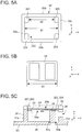
FIG. 5A is a bottom view (i.e., a view as seen in +Z direction) showing a configuration of the lid portion ofEmbodiment 1; -
FIG. 5B is a bottom view (i.e., a view as seen in +Z direction) showing a configuration of the substrate member ofEmbodiment 1; -
FIG. 5C is a sectional view taken alongline 5C-5C inFIG. 3 showing a configuration of the substrate storage portion ofEmbodiment 1; -
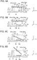
FIGS. 6A, 6B, 6C and 6D are schematic views showing a removing operation of the substrate member from the toner cartridge ofEmbodiment 1; -
FIGS. 7A, 7B, 7C and 7D are perspective views showing a configuration of a substrate storage portion ofEmbodiment 2; -
FIG. 8A is a bottom view (i.e., a view as seen in +Z direction) showing a configuration of a lid portion ofEmbodiment 2; -
FIG. 8B is a bottom view (i.e., a view as seen in +Z direction) showing a configuration of a substrate member ofEmbodiment 2; -
FIG. 8C is a sectional view showing a configuration of the substrate storage portion of Embodiment 2 (corresponding to a sectional view taken alongline 5C-5C inFIG. 3 ); -
FIGS. 9A, 9B, 9C and 9D are schematic views showing a removing operation of the substrate member from the toner cartridge ofEmbodiment 2; -
FIGS. 10A, 10B, 10C, 10D and 10E are bottom views (i.e., views as seen in +Z direction) showing examples of positions and shapes of a first support portion and a second support portion of modifications; -
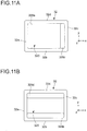
FIGS. 11A and 11B are bottom views (i.e., views as seen in +Z direction) showing configurations of lid portions of modifications. - Hereinafter, developer storage containers of embodiments of the present invention will be described with reference to the attached drawings. In order to facilitate understanding relationships between the drawings, an xyz orthogonal coordinate system is illustrated in the drawings. The x axis is a coordinate axis parallel to a longitudinal direction of a substrate storage portion. The y axis is a coordinate axis parallel to a widthwise direction of the substrate storage portion. The z axis is a coordinate axis parallel to a height direction of the substrate storage portion.
-
FIG. 1 is a sectional view schematically showing a configuration of aprinter 100 as an image forming apparatus including a developer storage container according toEmbodiment 1 of the present invention. Theprinter 100 is configured as an electrophotographic printer, and is configured to print an image of, for example, black (K). As shown inFIG. 1 , theprinter 100 ofEmbodiment 1 includes animage drum unit 10 detachably mounted in a main body of theprinter 100, acassette 2 as a medium storage portion storing recording sheets (media) 1, a hoppingroller 3a as a medium feeding member, a pair oftransport rollers 3b as medium transport members, atransfer roller 4 as a transfer member, a fixingunit 5 as a fixing device, an LED (Light Emitting Diode)head 6 as a latent image forming device, andejection rollers 7 as medium ejection members. -
FIG. 2 is a sectional view schematically showing a configuration of theimage drum unit 10 ofEmbodiment 1. As shown inFIG. 2 , theimage drum unit 10 includes aphotosensitive drum 11 as an image bearing body, a chargingroller 12, a developingroller 13 as a developing member, atoner supplying roller 14, a developingblade 15, a cleaningroller 16, atoner storage chamber 17, anagitation bar 18, and atoner cartridge 19. - The photosensitive drum 11 (i.e., an image bearing body) is configured to bear an electrostatic latent image and a toner image (i.e., a developer image) thereon. The charging roller 12 (i.e., a charging member) is configured to uniformly charge a surface of the
photosensitive drum 11. The chargingroller 12 is disposed so as to contact thephotosensitive drum 11. - The developing roller 13 (i.e., a developer bearing body) is configured to bear a toner (i.e., a developer) to be supplied to the
photosensitive drum 11. The developingroller 13 is disposed so as to contact thephotosensitive drum 11. The developingroller 13 bears the toner, and rotates to supply the toner to thephotosensitive drum 11. The developingroller 13 develops (visualizes) the electrostatic latent image on thephotosensitive drum 11 to form a toner image (i.e., a developer image) by causing the toner to adhere to the surface of thephotosensitive drum 11. - The toner supplying roller 14 (i.e., a developer supplying member) is configured to supply the toner to the developing
roller 13. Thetoner supplying roller 14 is disposed so as to contact the developingroller 13. The developing blade 15 (i.e., a developer layer thickness regulation member) is configured to regulate a thickness of a layer of the toner supplied to the developingroller 13. The developingblade 15 is disposed so that a tip (i.e., a bent portion) thereof contacts the developingroller 13. - The cleaning roller 16 (i.e., a developer removing member) is configured to remove the toner remaining on the surface of the
photosensitive drum 11 after a transfer process. The toner storage chamber 17 (i.e., a developer storage chamber) is configured to temporarily store the toner to be supplied to the developingroller 13. The agitation bar 18 (i.e., an agitating member) is configured to agitate the toner inside thetoner storage chamber 17. - Further, the
image drum unit 10 includes thetoner cartridge 19 as an attachable/detachable replaceable unit. The toner cartridge 19 (i.e., a developer storage container) is configured to store the toner used for development.FIG. 3 is a perspective view showing an external configuration of thetoner cartridge 19 ofEmbodiment 1. As shown inFIG. 3 , thetoner cartridge 19 includes anouter cartridge 20, atoner supply opening 21, ashutter 22, aside cover 23 as a container wall, asubstrate member 24, and asubstrate storage portion 30 as a storage portion. - As shown in
FIG. 3 , theouter cartridge 20 is a main body of thetoner cartridge 19, and stores the toner therein. Theouter cartridge 20 has a bottom portion (i.e., a cylindrical portion) having a cylindrical shape. - As shown in
FIG. 3 , thetoner supply opening 21 is provided on a bottom portion of thetoner cartridge 19. The toner supply opening 21 (i.e., a developer supply opening) is provided for supplying the toner from thetoner cartridge 19 to thetoner storage chamber 17. Thetoner supply opening 21 is opened and closed by theshutter 22 as an opening-and-closing member. - As shown in
FIG. 3 , theshutter 22 having a substantially cylindrical shape is rotatably provided, and protrudes through a side of theouter cartridge 20 in a longitudinal direction. When a toner ejection opening formed on a cylindrical wall of theshutter 22 is aligned with thetoner supply opening 21, the toner stored in thetoner cartridge 19 falls through thetoner supply opening 21, and is supplied to thetoner storage chamber 17. - As shown in
FIG. 3 , theside cover 23 is provided on the other side of the outer cartridge 20 (i.e., opposite to the side through which theshutter 22 protrudes) in the longitudinal direction. The side cover 23 is configured to cover a side surface of theouter cartridge 20. Thesubstrate storage portion 30 is formed on theside cover 23, and thesubstrate member 24 is stored in thesubstrate storage portion 30. -
FIGS. 4A through 4D are enlarged perspective views showing configurations of thesubstrate member 24 and thesubstrate storage portion 30 ofEmbodiment 1.FIG. 4A is a perspective view showing a configuration of thesubstrate storage portion 30. As shown inFIG. 4A through 4D , thesubstrate storage portion 30 includes an outer surroundingwall 31 surrounding thesubstrate member 24, alid portion 32, afirst support portion 33 and asecond support portion 34. Thefirst support portion 33 and thesecond support portion 34 are formed on abottom portion 36 of thesubstrate storage portion 30, and support thesubstrate member 24. In this regard, thebottom portion 36 of thesubstrate storage portion 30 may be formed integrally with the side cover 23 (i.e., the container wall). - As shown in
FIG. 4A , thesubstrate storage portion 30 has a rectangular shape as seen in +z axis direction. A through-hole 35 is formed on a side (i.e., aside 31c described later) of the outer surroundingwall 31. A plurality ofinsertion holes wall 31.Protrusions lid portion 32 are inserted into the insertion holes 311, 312, 313 and 314. Theouter surrounding wall 31 of thesubstrate storage portion 30 has aside 31a (i.e., a first side) and aside 31c (i.e., a second side) extending in the widthwise direction, and aside 31b (i.e., a third side) and aside 31d (i.e., a fourth side) extending in the longitudinal direction. In other words, thesides sides - As shown in
FIG. 4A , thefirst support portion 33 includes a substrate support stand 330 (i.e., a first substrate support stand) and a substrate support stand 331 (i.e., a second substrate support stand). In an example shown inFIG. 4A , thesubstrate member 24 is supported by a three-point support structure including the substrate support stand 330 of thefirst support portion 33, the substrate support stand 331 of thefirst support portion 33, and thesecond support portion 34. - Each of the substrate support stands 330 and 331 has, for example, a square column shape (or a rectangular parallelepiped shape). The
first support portion 33 is disposed besides (i.e., so as to face), for example, theside 31a. As shown inFIG. 4A , thesecond support portion 34 is disposed beside (i.e., so as to face) theside 31c opposite to theside 31a beside which thefirst support portion 33 is disposed. Thesecond support portion 34 has, for example, a circular cylinder shape. Shapes of the substrate support stands 330 and 331 are not limited to those shown inFIG. 4A . For example, each of the substrate support stands 330 and 331 may have a circular cylinder shape. A shape of thesecond support portion 34 is not limited to that shown inFIG. 4A . Thesecond support portion 34 may have a square column shape. -
FIG. 4B is a perspective view showing a state where thesubstrate member 24 is mounted in thesubstrate storage portion 30. As shown inFIG. 4B , thesubstrate member 24 is placed on top surfaces of the substrate support stands 330 and 331 of thefirst support portion 33 and thesecond support portion 34, and is supported by the three-point support structure including the substrate support stands 330 and 331 and thesecond support portion 34. -
FIG. 4C is a perspective view showing a configuration of thelid portion 32 fixed to a top surface of thesubstrate storage portion 30. As shown inFIG. 4C , thelid portion 32 has a rectangular shape as seen in +z axis direction. As shown inFIG. 4C , thelid portion 32 includesprotrusions 321 and 322 (i.e., first protrusions) provided on a side (i.e., aside 32a described later) of thelid portion 32, andprotrusions 323 and 324 (i.e., second protrusions) provided on the other side (i.e., aside 32c described later) of thelid portion 32. Theprotrusions substrate member 24, and restrict a movement of thesubstrate member 24 in a thickness direction (i.e., +z axis direction). - In this regard, in a state where the
lid portion 32 is fixed to theouter surrounding wall 31 of thesubstrate storage portion 30, theprotrusions substrate member 24. A clearance (i.e., a gap) may be formed between theprotrusions substrate member 24. Even when the clearance exists, thesubstrate member 24 is pressed by a contact pin (not shown) toward thesubstrate storage portion 30, and is fixed to thesubstrate storage portion 30. The contact pin is provided on a surface in theprinter 100 facing the side surface of thetoner cartridge 19 in the longitudinal direction. - Further, as shown in
FIG. 4C , thelid portion 32 includesprotrusions protrusions lid portion 32 are press-fitted (or welded, bonded or the like) into the insertion holes 311, 312, 313 and 314 of the outer surroundingwall 31, and thelid portion 32 is fixed to theouter surrounding wall 31 of thesubstrate storage portion 30. Thelid portion 32 includes aside 32a (i.e., a fifth side) and aside 32c (i.e., a sixth side) extending in the widthwise direction, and aside 32b (i.e., a seventh side) and aside 32d (i.e., an eighth side) extending in the longitudinal direction. In other words, thesides sides -
FIG. 4D is a perspective view showing a state where thelid portion 32 is fixed to thesubstrate storage portion 30 storing thesubstrate member 24. As shown inFIG. 4D , thelid portion 32 presses asurface 24b (i.e., a second surface) of thesubstrate member 24 opposite to asurface 24a (i.e., a first surface) of thesubstrate member 24 facing thebottom portion 36 of thesubstrate storage portion 30. Thelid portion 32 presses thesurface 24b of thesubstrate member 24 in -z axis direction. In a state where thesubstrate member 24 is stored in thesubstrate storage portion 30, thelid portion 32 is fixed to theouter surrounding wall 31 of thesubstrate storage portion 30 by press-fitting theprotrusions lid portion 32 into the insertion holes 311, 312, 313 and 314 of the outer surroundingwall 31. -
FIG. 5A is a bottom view (i.e., a view as seen in +z axis direction) showing a configuration of thelid portion 32 ofEmbodiment 1.FIG. 5B is a bottom view (i.e., a view as seen in +z axis direction) showing a configuration of thesubstrate member 24 ofEmbodiment 1.FIG. 5C is a sectional view taken alongline 5C-5C inFIG. 3 showing a configuration of thesubstrate storage portion 30 ofEmbodiment 1. - As shown in
FIG. 5A , theprotrusions sides lid portion 32 facing each other. To be more specific, theprotrusions side 32a of thelid portion 32. Theprotrusions side 32b of thelid portion 32. Theprotrusions lid portion 32. Alternatively, theprotrusions lid portion 32 using adhesive agent or the like. As shown inFIG. 5A , thelid portion 32 has anopening 320 having a length d1 in the longitudinal direction (i.e., the x axis direction). - As shown in
FIG. 5A , a distance between theside 32a and theside 32c (i.e., two sides of thelid portion 32 facing each other) of thelid portion 32 is the same as the length d1 of theopening 320 of thelid portion 32 in the longitudinal direction. Further, a distance between theprotrusion 321 and theprotrusion 323 of thelid portion 32 is expressed as d2. Here, the length d1 of theopening 320 of thelid portion 32 in the longitudinal direction is longer than the distance d2 between theprotrusion 321 and theprotrusion 323 of thelid portion 32. That is, the length d1 and the distance d2 satisfy a relationship: d1>d2. - As shown in
FIG. 5B , a length of thesubstrate member 24 in the longitudinal direction (i.e., the x axis direction) is d3. Here, the length d3 of thesubstrate member 24 in the longitudinal direction (i.e., the x axis direction) is shorter than the length d1 of theopening 320 of thelid portion 32 in the longitudinal direction, and longer than the distance d2 between theprotrusion 321 and the protrusion 323 (i.e., a length between the first protrusion and the second protrusion) of thelid portion 32. That is, the length d1, the distance d2 and the distance d3 satisfy a relationship: d1>d3>d2. With such a relationship (particularly, d3>d2), when thesubstrate member 24 is stored in thesubstrate storage portion 30 and is fixed by thelid portion 32, a movement of thesubstrate member 24 in the thickness direction (i.e., +z axis direction) is restricted by theprotrusions lid portion 32. Therefore, thesubstrate member 24 is prevented from being removed from thesubstrate storage portion 30. - As shown in
FIG. 5C , thesecond support portion 34 is connected to thebottom portion 36 of thesubstrate storage portion 30 at a connectingportion 34a in the form of a thin-walled portion. As shown inFIG. 5C , the connectingportion 34a is made thinner than a portion of thebottom portion 36 around (i.e., adjacent to) the connectingportion 34a. Since thesecond support portion 34 is connected to thebottom portion 36 of thesubstrate storage portion 30 at the connectingportion 34a (i.e., the thin-walled portion), thebottom portion 36 of thesubstrate storage portion 30 can be easily broken. - First, an operation of the
printer 100 having the above described configuration will be described with reference toFIG. 1 . - When the
printer 100 starts a printing operation, the hoppingroller 3a rotates to feed therecording sheet 1 out of thecassette 2. Thetransport rollers 3b transport therecording sheet 1 to theimage drum unit 10 along a sheet transport path. Theimage drum unit 10 transfers the toner image to a recording surface of therecording sheet 1. The fixingunit 5 fixes the transferred toner image to therecording sheet 1. Theejection rollers 7 eject therecording sheet 1 with the fixed toner image outside theprinter 100. - An operation of the
image drum unit 10 in the printing operation will be described with reference toFIG. 2 . - In the
image drum unit 10, thetoner supplying roller 14 supplies the toner (replenished from the toner cartridge 19) to the developingroller 13. The developingblade 15 forms a toner layer having a uniform thickness on the developingroller 13. TheLED head 6 forms an electrostatic latent image on the imagephotosensitive drum 11 according to print data. The electrostatic latent image is developed (visualized) with the toner on the developingroller 13. The toner image on thephotosensitive drum 11 is transferred to therecording sheet 1 by thetransfer roller 4. After the transfer of the toner image, the toner remaining on the surface of thephotosensitive drum 11 is removed by the cleaningroller 16. - Next, a removing operation of the
substrate member 24 from thetoner cartridge 19 will be described with reference toFIGS. 6A through 6D . -
FIGS. 6A through 6D are views for showing the removing operation of thesubstrate member 24 from thetoner cartridge 19 ofEmbodiment 1. When the usedtoner cartridges 19 are recovered, thesubstrate members 24 are removed from thetoner cartridges 19, and thetoner cartridges 19 are classified.FIGS. 6A through 6D corresponds to sectional views taken alongline 5C-5C inFIG. 3 . - In a state shown in
FIG. 6A , theprotrusion lid portion 32 restrict thesubstrate member 24 from moving upward (i.e., +z axis direction). In this state, thesubstrate member 24 cannot be removed from thesubstrate storage portion 30. As shown inFIG. 6A , the through-hole 35 is formed on theside 31c of the outer surroundingwall 31 of thesubstrate storage portion 30. The through-hole 35 is disposed so as to face thesecond support portion 34. - In the removing operation of the
substrate member 24 from thetoner cartridge 19, a tool or the like is inserted through the through-hole 35 of the outer surroundingwall 31 of thesubstrate storage portion 30 as shown inFIG. 6A . Then, thesecond support portion 34 is pressed using the tool so as to break the connectingportion 34a (i.e., the thin-walled portion). As the connectingportion 34a is broken, thesecond support portion 34 is disconnected from thebottom portion 36 of thesubstrate storage portion 30. - As shown in
FIG. 6B , thesecond support portion 34 falls down on thebottom portion 36 of thesubstrate storage portion 30, and rolls on thebottom portion 36 toward theside 31a. As shown inFIG. 6C , breaking of thesecond support portion 34 causes one of the three-point support structure supporting thesubstrate member 24 to be lost. Therefore, one side of thesubstrate member 24 falls down and contacts thebottom portion 36 of thesubstrate storage portion 30. In this state, thesubstrate member 24 is inclined. - As shown in
FIG. 6D , theinclined substrate member 24 is picked out using a tool, a user's hand or the like. In the state shown inFIG. 6D , thesubstrate member 24 is inclined as thesecond support portion 34 is broken, and thesubstrate member 24 can be easily removed from thesubstrate storage portion 30, without being interfered with theprotrusions lid portion 32.. - According to the developer storage container (i.e., the toner cartridge 19) of
Embodiment 1, thesubstrate storage portion 30 includes thefirst support portion 33 and thesecond support portion 34. Thesecond support portion 34 can be broken by being pressed by the tool or the like inserted through the through-hole 35 of the outer surroundingwall 31 of thesubstrate storage portion 30. By breaking thesecond support portion 34, one side of thesubstrate member 24 falls down on thebottom portion 36 of thesubstrate storage portion 30, and thesubstrate member 24 is inclined. Therefore, thesubstrate member 24 can be easily removed without being interfered with theprotrusions lid portion 32 of thesubstrate storage portion 30. Accordingly, classification work can be effectively performed. -
FIG. 7A through 7D are perspective views showing a configuration of asubstrate storage portion 30a ofEmbodiment 2 of the present invention.FIGS. 8A is a bottom view (i.e., a view as seen in +z axis direction) showing a configuration of alid portion 32e ofEmbodiment 2.FIG. 8B is a bottom view (i.e., a view as seen in +z axis direction) showing a configuration of asubstrate member 24 ofEmbodiment 2.FIG. 8C is a sectional view (corresponding to a sectional view taken alongline 5C-5C inFIG. 3 ) showing a configuration of asubstrate storage portion 30a ofEmbodiment 2.FIGS. 9A through 9D are views showing a removing operation of thesubstrate member 24 from atoner cartridge 19 ofEmbodiment 2. - In
FIGS. 7A through 7D , elements which are the same as or correspond to those shown inFIGS. 4A through 4D are assigned with the same reference numerals as those shown inFIGS. 4A through 4D . InFIGS. 8A through 8D , elements which are the same as or correspond to those shown inFIGS. 5A through 5D are assigned with the same reference numerals as those shown inFIGS. 5A through 5D . InFIGS. 9A through 9D , elements which are the same as or correspond to those shown inFIGS. 6A through 6D are assigned with the same reference numerals as those shown inFIGS. 6A through 6D . - The
substrate storage portion 30a ofEmbodiment 2 differs from thesubstrate storage portion 30 ofEmbodiment 1 in shape of asecond support portion 34b. Further, thelid portion 32e ofEmbodiment 2 differs from thelid portion 32 ofEmbodiment 1 in positions and shapes of protrusions 321e, 322e, 323e and 324e. Other configurations are the same as those ofEmbodiment 1, and descriptions thereof will be omitted. - As shown in
FIG. 7A , thesecond support portion 34b ofEmbodiment 2 has a rectangular parallelepiped shaped (i.e., a rib shape). Further, as shown inFIG. 8C , a connecting portion between thesecond support portion 34b and thebottom portion 36 of thesubstrate storage portion 30a ofEmbodiment 2 is sufficiently thin in the x axis direction. That is, the connecting portion can be easily broken without providing a thin-walled portion. Therefore, the thin-walled portion described inEmbodiment 1 is not provided inEmbodiment 2. - As shown in
FIG. 7C andFIG. 8A , theprotrusions side 32b and theside 32d of thelid portion 32e facing each other. Theprotrusions side 32b in +y direction. Theprotrusions side 32d in -y direction. As shown inFIG. 7C andFIG. 8A , each of theprotrusions - As shown in
FIGS. 8A and 8B , a length d3 of thesubstrate member 24 in the longitudinal direction (i.e., the x axis direction) is shorter than the length d1 of theopening 320 of thelid portion 32e in the longitudinal direction, and is longer than the distance d4 between theprotrusion 321e and theprotrusion 323e of thelid portion 32e. That is, the length d1, the length d3 and the distance d3 satisfy a relationship d1>d3>d4. With such a relationship (particularly d3>d4), when thesubstrate member 24 is stored in thesubstrate storage portion 30a and is fixed by thelid portion 32e, a movement of thesubstrate member 24 in the thickness direction (i.e., +z axis direction) is restricted by theprotrusions lid portion 32e. Therefore, thesubstrate member 24 is prevented from being removed from thesubstrate storage portion 30a. - According to the developer storage container (i.e., the toner cartridge 19) of
Embodiment 2, the same effect as that of the developer storage container ofEmbodiment 1 can be obtained. - According to the developer storage container (i.e., the toner cartridge 19) of
Embodiment 2, thesecond support portion 34b has a rectangular parallelepiped shape, and has a large surface facing the through-hole 35 of the outer surroundingwall 31. Therefore, thesecond support portion 34b can be easily broken by a tool or the like inserted through the through-hole 35 of the outer surroundingwall 31. - According to the developer storage container (i.e., the toner cartridge 19) of
Embodiment 2, the connecting portion between thesecond support portion 34b and thebottom portion 36 of thesubstrate storage portion 30a is thin in the x axis direction. Therefore, the connecting portion can be easily broken without providing a thin-walled portion, and a manufacturing process can be simplified. - The present invention is not limited to the above-described embodiments, but modifications may be made without departing from the scope of the invention. For example, in the above described embodiments, the
printer 100 is described as an example of the image forming apparatus. However, the present invention is also applicable to a copier, a facsimile machine, a MFP (MultiFunction Peripheral) having these functions, or the like. Further, the substrate support structure of the present invention is applicable to other apparatuses than the image forming apparatus. -
FIGS. 10A through 10E are bottom views (i.e., views as seen in +z axis direction) showing positions and shapes of thefirst support portion 33 and thesecond support portion 34 of modifications. In the above described embodiments, thefirst support portion 33 is disposed besides theside 31a of the outer surroundingwall 31, and thesecond support portion 34 is disposed beside theside 31c of the outer surroundingwall 31. However, the positions and numbers of thefirst support portion 33 and thesecond support portion 34 are not limited to those shown inFIGS. 4A and7A . Thefirst support portion 33 and thesecond support portion 34 may be formed and disposed as shown inFIGS. 10A through 10E . - In each of
FIGS. 10A through 10E , an arrow indicates a direction in which thesubstrate member 24 falls down. In the above described embodiment, thesubstrate member 24 falls down and is inclined in the x axis direction as shown inFIG. 6C . In other words, thesubstrate member 24 falls down in such a manner that the side (i.e., the shorter side) of thesubstrate member 24 extending in the y axis direction contacts thebottom portion 36 of thesubstrate storage portion 30. However, thesubstrate member 24 may fall down and be inclined in the Y axis direction. In other words, thesubstrate member 24 may fall down in such a manner the side (i.e., the longer side) of thesubstrate member 24 extending in the X direction may contact thebottom portion 36 of thesubstrate storage portion 30. For example, in configurations shown inFIGS. 10A, 10C and 10D , thesubstrate member 24 falls down and is inclined in the X axis direction. In configurations shown inFIGS. 10B and 10E , thesubstrate member 24 falls down and is inclined in the Y axis direction. - In the above described embodiments, the
first support portion 33 and thesecond support portion 34 are disposed beside thesides FIG. 4A ). However, thefirst support portion 33 and thesecond support portion 34 may be disposed beside thesides wall 31 as shown inFIGS. 10A, 10C and 10D . - In the above described embodiments, the
second support portion 34 is configured as a single substrate support stand (seeFIG. 4A ). However, thesecond support portion 34 may be configured as two or more substrate support stands as shown inFIGS. 10A, 10D and 10E . In this case, thesecond support portion 34 may include athird substrate support 341 stand and a fourth substrate support stand 342 that support thesubstrate member 24 as shown inFIGS. 10A, 10D and 10E . The fourth substrate support stand 342 may be disposed at a distance from the thirdsubstrate support stand 341. In the case where thesecond support portion 34 is configured as two or more substrate support stands, thefirst support portion 33 may be configured as a single substrate support stand so as to obtain the three-point support structure as shown inFIGS. 10D and 10E . Further, both of thefirst support portion 33 and thesecond support portion 34 may be configured as single substrate supports as shown inFIGS. 10B and 10C . -
FIGS. 11A and 11B are bottom views (i.e., views as seen in +z axis direction) showing a configuration of thelid portion 32 of modifications. In the above described embodiments, thelid portion 32 have theprotrusions FIG. 5A . However, as shown inFIG. 11A , thelid portion 32 may haveprotrusions sides lid portion 32. Further, as shown inFIG. 11B , thelid portion 32 may haveprotrusions sides lid portion 32. - The
lid portion 32 shown inFIG. 11A and thelid portion 32 shown inFIG. 11B may be coupled with the substrate storage portion 30 (FIG. 4A ) ofEmbodiment 1, thesubstrate storage portion 30a (FIG. 7A ) ofEmbodiment 2, and the substrate storage portion 30 (FIGS. 10A through 10E ) of the modifications. - While the preferred embodiments of the present invention have been illustrated in detail, it should be apparent that modifications and improvements may be made to the invention without departing from the spirit and scope of the invention as described in the following claims.
Claims (16)
- A developer storage container (19) comprising:a container wall (23);a substrate member (24) having a first surface (24a) and a second surface (24b) opposite to each other; anda storage portion (30, 30a) provided on the container wall (23) and storing the substrate member (24),wherein the storage portion (30, 30a) comprises:an outer surrounding wall (31) provided on the container wall (23);a first support portion (33) disposed inside the outer surrounding wall (31), the first support portion (33) supporting the first surface (24a) of the substrate member (24);a second support portion (34) disposed inside the outer surrounding wall (31) and connected to the container wall (23), the second support portion (34) supporting the first surface (24a) of the substrate member (24); anda lid portion (32, 32e) fixed to the outer surrounding wall (31) and having an opening (320) through which the substrate member (24) is exposed, the lid portion (32, 32e) contacting the second surface (24b) of the substrate member (24),wherein the lid portion (32, 32e) includes a first protrusion (321, 322, 321e, 322e) and a second protrusion (323, 324, 323e, 324e) protruding in a second direction perpendicular to a first direction from the substrate member (24) to the container wall (23);wherein a distance (d2, d4) between the first protrusion (321, 322, 321e, 322e) and the second protrusion (323, 324, 323e, 324e) in the second direction is shorter than a length (d3) of the substrate member (24) in the second direction; andwherein the outer surrounding wall (31) has a through-hole (35) disposed so as to face the second support portion (34).
- The developer storage container (19) according to claim 1, wherein a connecting portion (34a) between the second support portion (34) and the container wall (23) is thinner than a portion of the container wall (23) around the connecting portion (34a).
- The developer storage container (19) according to claim 1 or 2, wherein the outer surrounding wall (31) has a rectangular shape as seen in the first direction;
wherein the outer surrounding wall (31) has a first side (31a) and a second side (31c) opposing each other and defining shorter sides of the rectangular shape, and a third side (31b) and a fourth side (31d) opposing each other and defining longer sides of the rectangular shape;
wherein the lid portion (32, 32e) has a rectangular shape as seen in the first direction;
wherein the lid portion (32, 32e) has a fifth side (32a) and a sixth side (32c) opposing each other and defining shorter sides of the rectangular shape, and a seventh side (32b) and an eighth side (32d) opposing each other and defining longer sides of the rectangular shape. - The developer storage container (19) according to claim 3, wherein the first support portion (33) is disposed so as to face the first side (31a) of the outer surrounding wall (31);
wherein the second support portion (34) is disposed so as to face the second side (31c) of the outer surrounding wall (31);
wherein the first protrusion (321, 322, 321e, 322e) is disposed so as to face the fifth side (32a) of the lid portion (32, 32e); and
wherein the second protrusion (323, 324, 323e, 324e) is disposed so as to face the sixth side (32c) of the lid portion (32, 32e). - The developer storage container (19) according to claim 3, wherein the first support portion (33) is disposed so as to face the third side (31b) of the outer surrounding wall (31);
wherein the second support portion (34) is disposed so as to face the fourth side (31d) of the outer surrounding wall (31) ;
wherein the first protrusion (321, 322, 321e, 322e) is disposed so as to face the fifth side (32a) of the lid portion (32, 32e); and
wherein the second protrusion (323, 324, 323e, 324e) is disposed so as to face the sixth side (32c) of the lid portion (32, 32e). - The developer storage container (19) according to claim 3, wherein the first support portion (33) is disposed so as to face the first side (31a) of the outer surrounding wall (31);
wherein the second support portion (34) is disposed so as to face the second side (31c) of the outer surrounding wall (31);
wherein the first protrusion (321, 322, 321e, 322e) is provided so as to face the seventh side (32b) of the lid portion (32, 32e); and
wherein the second protrusion (323, 324, 323e, 324e) is disposed so as to face the eighth side (32d) of the lid portion (32, 32e). - The developer storage container (19) according to claim 3, wherein the first support portion (33) is disposed so as to face the third side (31b) of the outer surrounding wall (31);
wherein the second support portion (34) is disposed so as to face the fourth side (31d) of the outer surrounding wall (31);
wherein the first protrusion (321, 322, 321e, 322e) is disposed so as to face the seventh side (32b) of the lid portion (32, 32e); and
wherein the second protrusion (323, 324, 323e, 324e) is disposed so as to face the eighth side (32d) of the lid portion (32, 32e). - The developer storage container (19) according to any one of claims 1 to 7, wherein at least one of a surface of the first protrusion (321, 322, 321e, 322e) contacting the substrate member (24) and a surface of the second protrusion (323, 324, 323e, 324e) contacting the substrate member (24) has an elongated shape as seen in the first direction.
- The developer storage container (19) according to any one of claims 1 to 7, wherein the first support portion (33) includes:a first substrate support stand (330) supporting the substrate member (24), anda second substrate support stand (331) disposed apart from the first substrate support stand (330) and supporting the substrate member (24).
- The developer storage container (19) according to any one of claims 1 to 9, wherein the second support portion (34) includes:a third substrate support stand (34) supporting the substrate member (24), anda fourth substrate support stand (34) disposed apart from the third support stand and supporting the substrate member (24).
- The developer storage container (19) according to any one of claims 1 to 10, wherein the second support portion (34) has a cylindrical shape.
- The developer storage container (19) according to any one of claims 1 to 11, wherein the second support portion (34) has a rectangular parallelepiped shape.
- The developer storage container (19) according to any one of claims 1 to 12, wherein the lid portion (32, 32e) has a third protrusion (325, 326, 327, 328) protruding in the first direction,
wherein the outer surrounding wall (31) has an insertion hole (311, 312, 313, 314) into which the third protrusion (325, 326, 327, 328) of the lid portion (32, 32e) is inserted. - A developing device (10) comprising:the developer storage container (19) according to any one of claims 1 to 13, anda developer bearing body (13) that develops a latent image on an image bearing body (11) using a developer supplied by the developer storage container (19).
- An image forming apparatus (100) comprising:an image bearing body (11);a latent image forming device (6) that forms a latent image on the image bearing body (11); andthe developer storage container (19) according to any one of claims 1 to 13, anda developer bearing body (13) that develops the latent image on the image bearing body (11) using the developer supplied by the developer storage container (19).
- A substrate support structure comprising:a substrate member (24) having a first surface (24a) and a second surface (24b) opposite to each other; anda storage portion (30, 30a) storing the substrate member (24),wherein the storage portion (30, 30a) comprises:a bottom portion (36);an outer surrounding wall (31) provided on the bottom portion (36) and surrounding an outer circumference of the substrate member (24);a first support portion (33) disposed inside the outer surrounding wall (31) and supporting the first surface (24a) of the substrate member (24);a second support portion (34) disposed inside the outer surrounding wall (31) and supporting the first surface (24a) of the substrate member (24); anda lid portion (32, 32e) fixed to the outer surrounding wall (31) and having an opening through which the substrate member (24) is exposed, the lid portion (32, 32e) contacting the second surface (24b) of the substrate member (24),wherein the lid portion (32, 32e) includes a first protrusion (321, 322, 321e, 322e) and a second protrusion (323, 324, 323e, 324e) protruding in a second direction perpendicular to a first direction from the substrate member (24) to the bottom portion (32);wherein a distance (d2, d4) between the first protrusion (321, 322, 321e, 322e) and the second protrusion (323, 324, 323e, 324e) in the second direction is shorter than a length (d3) of the substrate member (24) in the second direction; andwherein the outer surrounding wall (31) has a through-hole (35) disposed so as to face the second support portion (34).
Applications Claiming Priority (1)
| Application Number | Priority Date | Filing Date | Title |
|---|---|---|---|
| JP2016128303A JP6596390B2 (en) | 2016-06-29 | 2016-06-29 | Developer container, developing device, image forming apparatus, and substrate support structure |
Publications (2)
| Publication Number | Publication Date |
|---|---|
| EP3264191A1 true EP3264191A1 (en) | 2018-01-03 |
| EP3264191B1 EP3264191B1 (en) | 2019-08-14 |
Family
ID=59034532
Family Applications (1)
| Application Number | Title | Priority Date | Filing Date |
|---|---|---|---|
| EP17175065.6A Active EP3264191B1 (en) | 2016-06-29 | 2017-06-08 | Developer storage container, developing device, image forming apparatus and substrate support structure |
Country Status (4)
| Country | Link |
|---|---|
| US (1) | US9927738B2 (en) |
| EP (1) | EP3264191B1 (en) |
| JP (1) | JP6596390B2 (en) |
| CN (1) | CN107544224A (en) |
Families Citing this family (4)
| Publication number | Priority date | Publication date | Assignee | Title |
|---|---|---|---|---|
| AU2019240065A1 (en) | 2018-03-20 | 2020-09-24 | Icahn School Of Medicine At Mount Sinai | Kinase inhibitor compounds and compositions and methods of use |
| CN108255039B (en) * | 2018-04-18 | 2020-11-03 | 中山市三润打印耗材有限公司 | A waste toner bin and a processing box |
| CA3124700A1 (en) | 2018-12-31 | 2020-07-09 | Icahn School Of Medicine At Mount Sinai | Kinase inhibitor compounds and compositions and methods of use |
| JP7581749B2 (en) * | 2020-10-01 | 2024-11-13 | 株式会社リコー | Toner storage container and image forming apparatus |
Citations (3)
| Publication number | Priority date | Publication date | Assignee | Title |
|---|---|---|---|---|
| US20080003014A1 (en) * | 2006-06-30 | 2008-01-03 | Static Control Components, Inc. | Systems and methods for remanufacturing imaging components |
| JP2012230237A (en) | 2011-04-26 | 2012-11-22 | Oki Data Corp | Information processing device, and image forming apparatus |
| US20150037050A1 (en) * | 2013-07-31 | 2015-02-05 | Hideki Kimura | Removable device and image forming apparatus |
Family Cites Families (14)
| Publication number | Priority date | Publication date | Assignee | Title |
|---|---|---|---|---|
| JPS61174799U (en) * | 1985-04-22 | 1986-10-30 | ||
| FR2778142B1 (en) * | 1998-04-30 | 2000-06-09 | Sagem | IMPROVED CARTRIDGE OF CONSUMABLE PRINTER PRODUCT |
| JP4498674B2 (en) * | 2002-12-24 | 2010-07-07 | 富士ゼロックス株式会社 | Memory chip, process cartridge, and image forming apparatus |
| JP4591222B2 (en) * | 2005-06-09 | 2010-12-01 | セイコーエプソン株式会社 | Electro-optical device and image forming apparatus |
| US7424245B2 (en) * | 2005-10-19 | 2008-09-09 | Static Control Components, Inc. | Systems and methods for remanufacturing imaging components |
| SG10201504616TA (en) * | 2010-06-11 | 2015-07-30 | Ricoh Co Ltd | Information storage device, removable device, developer container, and image forming apparatus |
| JP2012252178A (en) * | 2011-06-03 | 2012-12-20 | Ricoh Co Ltd | Toner bottle and image forming device |
| JP6018971B2 (en) * | 2013-05-20 | 2016-11-02 | 株式会社沖データ | Substrate mounting mechanism, developer container, image forming unit, and image forming apparatus |
| JP6338460B2 (en) * | 2013-08-20 | 2018-06-06 | キヤノン株式会社 | Cartridge and image forming apparatus |
| CN203433269U (en) * | 2013-08-27 | 2014-02-12 | 中山市迪迈模具塑胶有限公司 | Fastening structure of selenium drum conductive side cover |
| CN203433270U (en) * | 2013-08-27 | 2014-02-12 | 中山市迪迈模具塑胶有限公司 | Assembly structure of conductive side cover and chip of selenium drum |
| CN203561825U (en) * | 2013-10-31 | 2014-04-23 | 中山市迪迈模具塑胶有限公司 | Chip assembling structure of selenium drum |
| JP2014102506A (en) * | 2013-11-29 | 2014-06-05 | Canon Inc | Manufacturing method of cartridge having storage elements and replacement method of storage elements of cartridge, cartridge, and image forming apparatus |
| CN205281123U (en) * | 2016-01-15 | 2016-06-01 | 深圳超俊科技有限公司 | Selenium drum core piece buckle structure |
-
2016
- 2016-06-29 JP JP2016128303A patent/JP6596390B2/en active Active
-
2017
- 2017-06-08 US US15/617,042 patent/US9927738B2/en active Active
- 2017-06-08 EP EP17175065.6A patent/EP3264191B1/en active Active
- 2017-06-20 CN CN201710468830.0A patent/CN107544224A/en active Pending
Patent Citations (3)
| Publication number | Priority date | Publication date | Assignee | Title |
|---|---|---|---|---|
| US20080003014A1 (en) * | 2006-06-30 | 2008-01-03 | Static Control Components, Inc. | Systems and methods for remanufacturing imaging components |
| JP2012230237A (en) | 2011-04-26 | 2012-11-22 | Oki Data Corp | Information processing device, and image forming apparatus |
| US20150037050A1 (en) * | 2013-07-31 | 2015-02-05 | Hideki Kimura | Removable device and image forming apparatus |
Also Published As
| Publication number | Publication date |
|---|---|
| CN107544224A (en) | 2018-01-05 |
| US9927738B2 (en) | 2018-03-27 |
| JP2018004783A (en) | 2018-01-11 |
| US20180004122A1 (en) | 2018-01-04 |
| JP6596390B2 (en) | 2019-10-23 |
| EP3264191B1 (en) | 2019-08-14 |
Similar Documents
| Publication | Publication Date | Title |
|---|---|---|
| US9092007B2 (en) | Information processing apparatus and image forming apparatus having a first and second storage unit | |
| US8027596B2 (en) | Image forming apparatus | |
| US10935928B2 (en) | Cartridge | |
| US9927738B2 (en) | Developer storage container, developing device, image forming apparatus and substrate support structure | |
| CN110069003A (en) | Cartridge and image forming apparatus | |
| US20130236197A1 (en) | Powder container, toner cartridge, developing device, process unit, image forming apparatus, and method for recycling powder container | |
| JP2005257814A (en) | Process cartridge, electrophotographic image forming apparatus, and separation member | |
| JP2008299124A (en) | Toner cartridge | |
| US12474670B2 (en) | Cartridge unit | |
| US12321130B2 (en) | Cartridge, process cartridge, and image forming apparatus | |
| CN100547499C (en) | Photosensitive member cartridge, developing cartridge, and image forming device | |
| JP2007199457A (en) | Exchange unit and image forming apparatus | |
| JP6720490B2 (en) | Paper feeding device and image forming apparatus | |
| US8849164B2 (en) | Developer storage body, developing device and image forming apparatus | |
| CN100449421C (en) | image forming equipment | |
| JP6587437B2 (en) | Process cartridge | |
| JP6300517B2 (en) | Image forming apparatus and image forming apparatus main body | |
| US7319837B2 (en) | Developing unit and electrophotographic image forming apparatus having the same | |
| JP2009205082A (en) | Imaging cartridge and image forming apparatus | |
| US20220221810A1 (en) | Developing cartridge | |
| JP2005301077A (en) | Developing unit | |
| JP2022148518A (en) | Developer cartridge and image forming apparatus | |
| JP2019095585A (en) | Developer container, developing device, image forming apparatus, and substrate attachment part | |
| JP2007219228A (en) | Process unit |
Legal Events
| Date | Code | Title | Description |
|---|---|---|---|
| PUAI | Public reference made under article 153(3) epc to a published international application that has entered the european phase |
Free format text: ORIGINAL CODE: 0009012 |
|
| STAA | Information on the status of an ep patent application or granted ep patent |
Free format text: STATUS: THE APPLICATION HAS BEEN PUBLISHED |
|
| AK | Designated contracting states |
Kind code of ref document: A1 Designated state(s): AL AT BE BG CH CY CZ DE DK EE ES FI FR GB GR HR HU IE IS IT LI LT LU LV MC MK MT NL NO PL PT RO RS SE SI SK SM TR |
|
| AX | Request for extension of the european patent |
Extension state: BA ME |
|
| STAA | Information on the status of an ep patent application or granted ep patent |
Free format text: STATUS: REQUEST FOR EXAMINATION WAS MADE |
|
| 17P | Request for examination filed |
Effective date: 20180518 |
|
| RBV | Designated contracting states (corrected) |
Designated state(s): AL AT BE BG CH CY CZ DE DK EE ES FI FR GB GR HR HU IE IS IT LI LT LU LV MC MK MT NL NO PL PT RO RS SE SI SK SM TR |
|
| REG | Reference to a national code |
Ref country code: DE Ref legal event code: R079 Ref document number: 602017006054 Country of ref document: DE Free format text: PREVIOUS MAIN CLASS: G03G0015080000 Ipc: G03G0021160000 |
|
| GRAP | Despatch of communication of intention to grant a patent |
Free format text: ORIGINAL CODE: EPIDOSNIGR1 |
|
| STAA | Information on the status of an ep patent application or granted ep patent |
Free format text: STATUS: GRANT OF PATENT IS INTENDED |
|
| RIC1 | Information provided on ipc code assigned before grant |
Ipc: G03G 21/16 20060101AFI20190215BHEP Ipc: G03G 21/18 20060101ALI20190215BHEP Ipc: G03G 15/08 20060101ALI20190215BHEP |
|
| INTG | Intention to grant announced |
Effective date: 20190327 |
|
| GRAS | Grant fee paid |
Free format text: ORIGINAL CODE: EPIDOSNIGR3 |
|
| GRAA | (expected) grant |
Free format text: ORIGINAL CODE: 0009210 |
|
| STAA | Information on the status of an ep patent application or granted ep patent |
Free format text: STATUS: THE PATENT HAS BEEN GRANTED |
|
| AK | Designated contracting states |
Kind code of ref document: B1 Designated state(s): AL AT BE BG CH CY CZ DE DK EE ES FI FR GB GR HR HU IE IS IT LI LT LU LV MC MK MT NL NO PL PT RO RS SE SI SK SM TR |
|
| REG | Reference to a national code |
Ref country code: GB Ref legal event code: FG4D |
|
| REG | Reference to a national code |
Ref country code: CH Ref legal event code: EP Ref country code: AT Ref legal event code: REF Ref document number: 1167744 Country of ref document: AT Kind code of ref document: T Effective date: 20190815 |
|
| REG | Reference to a national code |
Ref country code: IE Ref legal event code: FG4D |
|
| REG | Reference to a national code |
Ref country code: DE Ref legal event code: R096 Ref document number: 602017006054 Country of ref document: DE |
|
| REG | Reference to a national code |
Ref country code: NL Ref legal event code: FP |
|
| REG | Reference to a national code |
Ref country code: LT Ref legal event code: MG4D |
|
| PG25 | Lapsed in a contracting state [announced via postgrant information from national office to epo] |
Ref country code: LT Free format text: LAPSE BECAUSE OF FAILURE TO SUBMIT A TRANSLATION OF THE DESCRIPTION OR TO PAY THE FEE WITHIN THE PRESCRIBED TIME-LIMIT Effective date: 20190814 Ref country code: HR Free format text: LAPSE BECAUSE OF FAILURE TO SUBMIT A TRANSLATION OF THE DESCRIPTION OR TO PAY THE FEE WITHIN THE PRESCRIBED TIME-LIMIT Effective date: 20190814 Ref country code: BG Free format text: LAPSE BECAUSE OF FAILURE TO SUBMIT A TRANSLATION OF THE DESCRIPTION OR TO PAY THE FEE WITHIN THE PRESCRIBED TIME-LIMIT Effective date: 20191114 Ref country code: SE Free format text: LAPSE BECAUSE OF FAILURE TO SUBMIT A TRANSLATION OF THE DESCRIPTION OR TO PAY THE FEE WITHIN THE PRESCRIBED TIME-LIMIT Effective date: 20190814 Ref country code: PT Free format text: LAPSE BECAUSE OF FAILURE TO SUBMIT A TRANSLATION OF THE DESCRIPTION OR TO PAY THE FEE WITHIN THE PRESCRIBED TIME-LIMIT Effective date: 20191216 Ref country code: FI Free format text: LAPSE BECAUSE OF FAILURE TO SUBMIT A TRANSLATION OF THE DESCRIPTION OR TO PAY THE FEE WITHIN THE PRESCRIBED TIME-LIMIT Effective date: 20190814 Ref country code: NO Free format text: LAPSE BECAUSE OF FAILURE TO SUBMIT A TRANSLATION OF THE DESCRIPTION OR TO PAY THE FEE WITHIN THE PRESCRIBED TIME-LIMIT Effective date: 20191114 |
|
| REG | Reference to a national code |
Ref country code: AT Ref legal event code: MK05 Ref document number: 1167744 Country of ref document: AT Kind code of ref document: T Effective date: 20190814 |
|
| PG25 | Lapsed in a contracting state [announced via postgrant information from national office to epo] |
Ref country code: RS Free format text: LAPSE BECAUSE OF FAILURE TO SUBMIT A TRANSLATION OF THE DESCRIPTION OR TO PAY THE FEE WITHIN THE PRESCRIBED TIME-LIMIT Effective date: 20190814 Ref country code: LV Free format text: LAPSE BECAUSE OF FAILURE TO SUBMIT A TRANSLATION OF THE DESCRIPTION OR TO PAY THE FEE WITHIN THE PRESCRIBED TIME-LIMIT Effective date: 20190814 Ref country code: IS Free format text: LAPSE BECAUSE OF FAILURE TO SUBMIT A TRANSLATION OF THE DESCRIPTION OR TO PAY THE FEE WITHIN THE PRESCRIBED TIME-LIMIT Effective date: 20191214 Ref country code: ES Free format text: LAPSE BECAUSE OF FAILURE TO SUBMIT A TRANSLATION OF THE DESCRIPTION OR TO PAY THE FEE WITHIN THE PRESCRIBED TIME-LIMIT Effective date: 20190814 Ref country code: AL Free format text: LAPSE BECAUSE OF FAILURE TO SUBMIT A TRANSLATION OF THE DESCRIPTION OR TO PAY THE FEE WITHIN THE PRESCRIBED TIME-LIMIT Effective date: 20190814 Ref country code: GR Free format text: LAPSE BECAUSE OF FAILURE TO SUBMIT A TRANSLATION OF THE DESCRIPTION OR TO PAY THE FEE WITHIN THE PRESCRIBED TIME-LIMIT Effective date: 20191115 |
|
| PG25 | Lapsed in a contracting state [announced via postgrant information from national office to epo] |
Ref country code: TR Free format text: LAPSE BECAUSE OF FAILURE TO SUBMIT A TRANSLATION OF THE DESCRIPTION OR TO PAY THE FEE WITHIN THE PRESCRIBED TIME-LIMIT Effective date: 20190814 |
|
| PG25 | Lapsed in a contracting state [announced via postgrant information from national office to epo] |
Ref country code: DK Free format text: LAPSE BECAUSE OF FAILURE TO SUBMIT A TRANSLATION OF THE DESCRIPTION OR TO PAY THE FEE WITHIN THE PRESCRIBED TIME-LIMIT Effective date: 20190814 Ref country code: EE Free format text: LAPSE BECAUSE OF FAILURE TO SUBMIT A TRANSLATION OF THE DESCRIPTION OR TO PAY THE FEE WITHIN THE PRESCRIBED TIME-LIMIT Effective date: 20190814 Ref country code: AT Free format text: LAPSE BECAUSE OF FAILURE TO SUBMIT A TRANSLATION OF THE DESCRIPTION OR TO PAY THE FEE WITHIN THE PRESCRIBED TIME-LIMIT Effective date: 20190814 Ref country code: IT Free format text: LAPSE BECAUSE OF FAILURE TO SUBMIT A TRANSLATION OF THE DESCRIPTION OR TO PAY THE FEE WITHIN THE PRESCRIBED TIME-LIMIT Effective date: 20190814 Ref country code: RO Free format text: LAPSE BECAUSE OF FAILURE TO SUBMIT A TRANSLATION OF THE DESCRIPTION OR TO PAY THE FEE WITHIN THE PRESCRIBED TIME-LIMIT Effective date: 20190814 Ref country code: PL Free format text: LAPSE BECAUSE OF FAILURE TO SUBMIT A TRANSLATION OF THE DESCRIPTION OR TO PAY THE FEE WITHIN THE PRESCRIBED TIME-LIMIT Effective date: 20190814 |
|
| PG25 | Lapsed in a contracting state [announced via postgrant information from national office to epo] |
Ref country code: IS Free format text: LAPSE BECAUSE OF FAILURE TO SUBMIT A TRANSLATION OF THE DESCRIPTION OR TO PAY THE FEE WITHIN THE PRESCRIBED TIME-LIMIT Effective date: 20200224 Ref country code: SM Free format text: LAPSE BECAUSE OF FAILURE TO SUBMIT A TRANSLATION OF THE DESCRIPTION OR TO PAY THE FEE WITHIN THE PRESCRIBED TIME-LIMIT Effective date: 20190814 Ref country code: SK Free format text: LAPSE BECAUSE OF FAILURE TO SUBMIT A TRANSLATION OF THE DESCRIPTION OR TO PAY THE FEE WITHIN THE PRESCRIBED TIME-LIMIT Effective date: 20190814 Ref country code: CZ Free format text: LAPSE BECAUSE OF FAILURE TO SUBMIT A TRANSLATION OF THE DESCRIPTION OR TO PAY THE FEE WITHIN THE PRESCRIBED TIME-LIMIT Effective date: 20190814 |
|
| REG | Reference to a national code |
Ref country code: DE Ref legal event code: R097 Ref document number: 602017006054 Country of ref document: DE |
|
| PLBE | No opposition filed within time limit |
Free format text: ORIGINAL CODE: 0009261 |
|
| STAA | Information on the status of an ep patent application or granted ep patent |
Free format text: STATUS: NO OPPOSITION FILED WITHIN TIME LIMIT |
|
| PG2D | Information on lapse in contracting state deleted |
Ref country code: IS |
|
| 26N | No opposition filed |
Effective date: 20200603 |
|
| PG25 | Lapsed in a contracting state [announced via postgrant information from national office to epo] |
Ref country code: SI Free format text: LAPSE BECAUSE OF FAILURE TO SUBMIT A TRANSLATION OF THE DESCRIPTION OR TO PAY THE FEE WITHIN THE PRESCRIBED TIME-LIMIT Effective date: 20190814 |
|
| REG | Reference to a national code |
Ref country code: DE Ref legal event code: R082 Ref document number: 602017006054 Country of ref document: DE Representative=s name: VENNER SHIPLEY GERMANY LLP, DE Ref country code: DE Ref legal event code: R082 Ref document number: 602017006054 Country of ref document: DE Representative=s name: BETTEN & RESCH PATENT- UND RECHTSANWAELTE PART, DE Ref country code: DE Ref legal event code: R082 Ref document number: 602017006054 Country of ref document: DE Representative=s name: VENNER SHIPLEY LLP, DE |
|
| PG25 | Lapsed in a contracting state [announced via postgrant information from national office to epo] |
Ref country code: MC Free format text: LAPSE BECAUSE OF FAILURE TO SUBMIT A TRANSLATION OF THE DESCRIPTION OR TO PAY THE FEE WITHIN THE PRESCRIBED TIME-LIMIT Effective date: 20190814 |
|
| REG | Reference to a national code |
Ref country code: CH Ref legal event code: PL |
|
| PG25 | Lapsed in a contracting state [announced via postgrant information from national office to epo] |
Ref country code: LU Free format text: LAPSE BECAUSE OF NON-PAYMENT OF DUE FEES Effective date: 20200608 |
|
| REG | Reference to a national code |
Ref country code: BE Ref legal event code: MM Effective date: 20200630 |
|
| PG25 | Lapsed in a contracting state [announced via postgrant information from national office to epo] |
Ref country code: IE Free format text: LAPSE BECAUSE OF NON-PAYMENT OF DUE FEES Effective date: 20200608 Ref country code: LI Free format text: LAPSE BECAUSE OF NON-PAYMENT OF DUE FEES Effective date: 20200630 Ref country code: CH Free format text: LAPSE BECAUSE OF NON-PAYMENT OF DUE FEES Effective date: 20200630 |
|
| PG25 | Lapsed in a contracting state [announced via postgrant information from national office to epo] |
Ref country code: BE Free format text: LAPSE BECAUSE OF NON-PAYMENT OF DUE FEES Effective date: 20200630 |
|
| REG | Reference to a national code |
Ref country code: DE Ref legal event code: R082 Ref document number: 602017006054 Country of ref document: DE Representative=s name: VENNER SHIPLEY GERMANY LLP, DE Ref country code: DE Ref legal event code: R081 Ref document number: 602017006054 Country of ref document: DE Owner name: OKI ELECTRIC INDUSTRY CO., LTD., JP Free format text: FORMER OWNER: OKI DATA CORP., TOKIO/TOKYO, JP Ref country code: DE Ref legal event code: R082 Ref document number: 602017006054 Country of ref document: DE Representative=s name: BETTEN & RESCH PATENT- UND RECHTSANWAELTE PART, DE |
|
| REG | Reference to a national code |
Ref country code: GB Ref legal event code: 732E Free format text: REGISTERED BETWEEN 20220317 AND 20220323 |
|
| REG | Reference to a national code |
Ref country code: NL Ref legal event code: PD Owner name: OKI ELECTRIC INDUSTRY CO., LTD.; JP Free format text: DETAILS ASSIGNMENT: CHANGE OF OWNER(S), MERGE; FORMER OWNER NAME: OKI DATA CORPORATION Effective date: 20220308 |
|
| PG25 | Lapsed in a contracting state [announced via postgrant information from national office to epo] |
Ref country code: MT Free format text: LAPSE BECAUSE OF FAILURE TO SUBMIT A TRANSLATION OF THE DESCRIPTION OR TO PAY THE FEE WITHIN THE PRESCRIBED TIME-LIMIT Effective date: 20190814 Ref country code: CY Free format text: LAPSE BECAUSE OF FAILURE TO SUBMIT A TRANSLATION OF THE DESCRIPTION OR TO PAY THE FEE WITHIN THE PRESCRIBED TIME-LIMIT Effective date: 20190814 |
|
| PG25 | Lapsed in a contracting state [announced via postgrant information from national office to epo] |
Ref country code: MK Free format text: LAPSE BECAUSE OF FAILURE TO SUBMIT A TRANSLATION OF THE DESCRIPTION OR TO PAY THE FEE WITHIN THE PRESCRIBED TIME-LIMIT Effective date: 20190814 |
|
| REG | Reference to a national code |
Ref country code: DE Ref legal event code: R082 Ref document number: 602017006054 Country of ref document: DE Representative=s name: VENNER SHIPLEY GERMANY LLP, DE |
|
| PGFP | Annual fee paid to national office [announced via postgrant information from national office to epo] |
Ref country code: NL Payment date: 20250516 Year of fee payment: 9 |
|
| PGFP | Annual fee paid to national office [announced via postgrant information from national office to epo] |
Ref country code: DE Payment date: 20250429 Year of fee payment: 9 |
|
| PGFP | Annual fee paid to national office [announced via postgrant information from national office to epo] |
Ref country code: GB Payment date: 20250501 Year of fee payment: 9 |
|
| PGFP | Annual fee paid to national office [announced via postgrant information from national office to epo] |
Ref country code: FR Payment date: 20250508 Year of fee payment: 9 |