EP3264186A1 - Image forming apparatus - Google Patents
Image forming apparatus Download PDFInfo
- Publication number
- EP3264186A1 EP3264186A1 EP17176610.8A EP17176610A EP3264186A1 EP 3264186 A1 EP3264186 A1 EP 3264186A1 EP 17176610 A EP17176610 A EP 17176610A EP 3264186 A1 EP3264186 A1 EP 3264186A1
- Authority
- EP
- European Patent Office
- Prior art keywords
- luminescent
- toner
- image
- fluorescent
- medium
- Prior art date
- Legal status (The legal status is an assumption and is not a legal conclusion. Google has not performed a legal analysis and makes no representation as to the accuracy of the status listed.)
- Granted
Links
- 238000000034 method Methods 0.000 claims abstract description 263
- 230000008569 process Effects 0.000 claims abstract description 249
- 238000012546 transfer Methods 0.000 claims abstract description 156
- 239000003086 colorant Substances 0.000 claims description 53
- 238000011161 development Methods 0.000 description 38
- 230000015572 biosynthetic process Effects 0.000 description 24
- 238000004140 cleaning Methods 0.000 description 21
- 238000007639 printing Methods 0.000 description 20
- 238000005516 engineering process Methods 0.000 description 19
- 239000000463 material Substances 0.000 description 17
- 239000011230 binding agent Substances 0.000 description 15
- 229910052751 metal Inorganic materials 0.000 description 15
- 239000002184 metal Substances 0.000 description 15
- 239000001993 wax Substances 0.000 description 14
- 238000010438 heat treatment Methods 0.000 description 12
- 239000003795 chemical substances by application Substances 0.000 description 11
- 230000008859 change Effects 0.000 description 10
- 230000004048 modification Effects 0.000 description 10
- 238000012986 modification Methods 0.000 description 10
- 239000000049 pigment Substances 0.000 description 10
- 238000012360 testing method Methods 0.000 description 9
- 239000000975 dye Substances 0.000 description 7
- 230000002349 favourable effect Effects 0.000 description 7
- 229920001225 polyester resin Polymers 0.000 description 7
- 230000002093 peripheral effect Effects 0.000 description 6
- 229920005989 resin Polymers 0.000 description 6
- 239000011347 resin Substances 0.000 description 6
- LYCAIKOWRPUZTN-UHFFFAOYSA-N Ethylene glycol Chemical compound OCCO LYCAIKOWRPUZTN-UHFFFAOYSA-N 0.000 description 5
- 239000000654 additive Substances 0.000 description 5
- 230000000996 additive effect Effects 0.000 description 5
- 230000006872 improvement Effects 0.000 description 5
- 239000007769 metal material Substances 0.000 description 5
- 230000004044 response Effects 0.000 description 5
- 239000007787 solid Substances 0.000 description 5
- LFQSCWFLJHTTHZ-UHFFFAOYSA-N Ethanol Chemical compound CCO LFQSCWFLJHTTHZ-UHFFFAOYSA-N 0.000 description 4
- 150000001338 aliphatic hydrocarbons Chemical class 0.000 description 4
- 230000008901 benefit Effects 0.000 description 4
- 150000001732 carboxylic acid derivatives Chemical class 0.000 description 4
- 150000001875 compounds Chemical class 0.000 description 4
- 230000003287 optical effect Effects 0.000 description 4
- 239000002861 polymer material Substances 0.000 description 4
- OKTJSMMVPCPJKN-UHFFFAOYSA-N Carbon Chemical compound [C] OKTJSMMVPCPJKN-UHFFFAOYSA-N 0.000 description 3
- DNIAPMSPPWPWGF-UHFFFAOYSA-N Propylene glycol Chemical compound CC(O)CO DNIAPMSPPWPWGF-UHFFFAOYSA-N 0.000 description 3
- VYPSYNLAJGMNEJ-UHFFFAOYSA-N Silicium dioxide Chemical compound O=[Si]=O VYPSYNLAJGMNEJ-UHFFFAOYSA-N 0.000 description 3
- 229910052782 aluminium Inorganic materials 0.000 description 3
- XAGFODPZIPBFFR-UHFFFAOYSA-N aluminium Chemical compound [Al] XAGFODPZIPBFFR-UHFFFAOYSA-N 0.000 description 3
- IISBACLAFKSPIT-UHFFFAOYSA-N bisphenol A Chemical compound C=1C=C(O)C=CC=1C(C)(C)C1=CC=C(O)C=C1 IISBACLAFKSPIT-UHFFFAOYSA-N 0.000 description 3
- 230000015556 catabolic process Effects 0.000 description 3
- 239000011248 coating agent Substances 0.000 description 3
- 238000000576 coating method Methods 0.000 description 3
- XCJYREBRNVKWGJ-UHFFFAOYSA-N copper(II) phthalocyanine Chemical compound [Cu+2].C12=CC=CC=C2C(N=C2[N-]C(C3=CC=CC=C32)=N2)=NC1=NC([C]1C=CC=CC1=1)=NC=1N=C1[C]3C=CC=CC3=C2[N-]1 XCJYREBRNVKWGJ-UHFFFAOYSA-N 0.000 description 3
- 230000003247 decreasing effect Effects 0.000 description 3
- 238000006731 degradation reaction Methods 0.000 description 3
- MTHSVFCYNBDYFN-UHFFFAOYSA-N diethylene glycol Chemical compound OCCOCCO MTHSVFCYNBDYFN-UHFFFAOYSA-N 0.000 description 3
- 230000000694 effects Effects 0.000 description 3
- 238000005562 fading Methods 0.000 description 3
- AJDUTMFFZHIJEM-UHFFFAOYSA-N n-(9,10-dioxoanthracen-1-yl)-4-[4-[[4-[4-[(9,10-dioxoanthracen-1-yl)carbamoyl]phenyl]phenyl]diazenyl]phenyl]benzamide Chemical compound O=C1C2=CC=CC=C2C(=O)C2=C1C=CC=C2NC(=O)C(C=C1)=CC=C1C(C=C1)=CC=C1N=NC(C=C1)=CC=C1C(C=C1)=CC=C1C(=O)NC1=CC=CC2=C1C(=O)C1=CC=CC=C1C2=O AJDUTMFFZHIJEM-UHFFFAOYSA-N 0.000 description 3
- -1 polytetrafluoroethylene Polymers 0.000 description 3
- 238000013441 quality evaluation Methods 0.000 description 3
- 239000001043 yellow dye Substances 0.000 description 3
- 239000001052 yellow pigment Substances 0.000 description 3
- VZCYOOQTPOCHFL-OWOJBTEDSA-N Fumaric acid Chemical compound OC(=O)\C=C\C(O)=O VZCYOOQTPOCHFL-OWOJBTEDSA-N 0.000 description 2
- PEDCQBHIVMGVHV-UHFFFAOYSA-N Glycerine Chemical compound OCC(O)CO PEDCQBHIVMGVHV-UHFFFAOYSA-N 0.000 description 2
- KKEYFWRCBNTPAC-UHFFFAOYSA-N Terephthalic acid Chemical compound OC(=O)C1=CC=C(C(O)=O)C=C1 KKEYFWRCBNTPAC-UHFFFAOYSA-N 0.000 description 2
- 229920006311 Urethane elastomer Polymers 0.000 description 2
- WNLRTRBMVRJNCN-UHFFFAOYSA-N adipic acid Chemical compound OC(=O)CCCCC(O)=O WNLRTRBMVRJNCN-UHFFFAOYSA-N 0.000 description 2
- 230000004075 alteration Effects 0.000 description 2
- 239000006229 carbon black Substances 0.000 description 2
- 239000004203 carnauba wax Substances 0.000 description 2
- 235000013869 carnauba wax Nutrition 0.000 description 2
- 229920001577 copolymer Polymers 0.000 description 2
- ZYGHJZDHTFUPRJ-UHFFFAOYSA-N coumarin Chemical compound C1=CC=C2OC(=O)C=CC2=C1 ZYGHJZDHTFUPRJ-UHFFFAOYSA-N 0.000 description 2
- ZUOUZKKEUPVFJK-UHFFFAOYSA-N diphenyl Chemical compound C1=CC=CC=C1C1=CC=CC=C1 ZUOUZKKEUPVFJK-UHFFFAOYSA-N 0.000 description 2
- 229910010272 inorganic material Inorganic materials 0.000 description 2
- 239000011147 inorganic material Substances 0.000 description 2
- QQVIHTHCMHWDBS-UHFFFAOYSA-N isophthalic acid Chemical compound OC(=O)C1=CC=CC(C(O)=O)=C1 QQVIHTHCMHWDBS-UHFFFAOYSA-N 0.000 description 2
- 230000014759 maintenance of location Effects 0.000 description 2
- 238000004519 manufacturing process Methods 0.000 description 2
- 239000011368 organic material Substances 0.000 description 2
- XNGIFLGASWRNHJ-UHFFFAOYSA-N phthalic acid Chemical compound OC(=O)C1=CC=CC=C1C(O)=O XNGIFLGASWRNHJ-UHFFFAOYSA-N 0.000 description 2
- 229920000642 polymer Polymers 0.000 description 2
- 238000006116 polymerization reaction Methods 0.000 description 2
- 229920001343 polytetrafluoroethylene Polymers 0.000 description 2
- 239000004810 polytetrafluoroethylene Substances 0.000 description 2
- CYIDZMCFTVVTJO-UHFFFAOYSA-N pyromellitic acid Chemical compound OC(=O)C1=CC(C(O)=O)=C(C(O)=O)C=C1C(O)=O CYIDZMCFTVVTJO-UHFFFAOYSA-N 0.000 description 2
- YGSDEFSMJLZEOE-UHFFFAOYSA-N salicylic acid Chemical compound OC(=O)C1=CC=CC=C1O YGSDEFSMJLZEOE-UHFFFAOYSA-N 0.000 description 2
- VZCYOOQTPOCHFL-UHFFFAOYSA-N trans-butenedioic acid Natural products OC(=O)C=CC(O)=O VZCYOOQTPOCHFL-UHFFFAOYSA-N 0.000 description 2
- ARCGXLSVLAOJQL-UHFFFAOYSA-N trimellitic acid Chemical compound OC(=O)C1=CC=C(C(O)=O)C(C(O)=O)=C1 ARCGXLSVLAOJQL-UHFFFAOYSA-N 0.000 description 2
- 239000012463 white pigment Substances 0.000 description 2
- 230000003245 working effect Effects 0.000 description 2
- FALRKNHUBBKYCC-UHFFFAOYSA-N 2-(chloromethyl)pyridine-3-carbonitrile Chemical compound ClCC1=NC=CC=C1C#N FALRKNHUBBKYCC-UHFFFAOYSA-N 0.000 description 1
- WVRNUXJQQFPNMN-VAWYXSNFSA-N 3-[(e)-dodec-1-enyl]oxolane-2,5-dione Chemical compound CCCCCCCCCC\C=C\C1CC(=O)OC1=O WVRNUXJQQFPNMN-VAWYXSNFSA-N 0.000 description 1
- VNGLVZLEUDIDQH-UHFFFAOYSA-N 4-[2-(4-hydroxyphenyl)propan-2-yl]phenol;2-methyloxirane Chemical compound CC1CO1.C=1C=C(O)C=CC=1C(C)(C)C1=CC=C(O)C=C1 VNGLVZLEUDIDQH-UHFFFAOYSA-N 0.000 description 1
- WPSWDCBWMRJJED-UHFFFAOYSA-N 4-[2-(4-hydroxyphenyl)propan-2-yl]phenol;oxirane Chemical compound C1CO1.C=1C=C(O)C=CC=1C(C)(C)C1=CC=C(O)C=C1 WPSWDCBWMRJJED-UHFFFAOYSA-N 0.000 description 1
- FBPFZTCFMRRESA-FSIIMWSLSA-N D-Glucitol Natural products OC[C@H](O)[C@H](O)[C@@H](O)[C@H](O)CO FBPFZTCFMRRESA-FSIIMWSLSA-N 0.000 description 1
- FBPFZTCFMRRESA-JGWLITMVSA-N D-glucitol Chemical compound OC[C@H](O)[C@@H](O)[C@H](O)[C@H](O)CO FBPFZTCFMRRESA-JGWLITMVSA-N 0.000 description 1
- 239000004593 Epoxy Substances 0.000 description 1
- 239000004640 Melamine resin Substances 0.000 description 1
- 229920000877 Melamine resin Polymers 0.000 description 1
- CTQNGGLPUBDAKN-UHFFFAOYSA-N O-Xylene Chemical compound CC1=CC=CC=C1C CTQNGGLPUBDAKN-UHFFFAOYSA-N 0.000 description 1
- 239000004698 Polyethylene Substances 0.000 description 1
- 239000002202 Polyethylene glycol Substances 0.000 description 1
- 239000004642 Polyimide Substances 0.000 description 1
- 239000004743 Polypropylene Substances 0.000 description 1
- OFOBLEOULBTSOW-UHFFFAOYSA-N Propanedioic acid Natural products OC(=O)CC(O)=O OFOBLEOULBTSOW-UHFFFAOYSA-N 0.000 description 1
- NRCMAYZCPIVABH-UHFFFAOYSA-N Quinacridone Chemical compound N1C2=CC=CC=C2C(=O)C2=C1C=C1C(=O)C3=CC=CC=C3NC1=C2 NRCMAYZCPIVABH-UHFFFAOYSA-N 0.000 description 1
- PJANXHGTPQOBST-VAWYXSNFSA-N Stilbene Natural products C=1C=CC=CC=1/C=C/C1=CC=CC=C1 PJANXHGTPQOBST-VAWYXSNFSA-N 0.000 description 1
- 239000002174 Styrene-butadiene Substances 0.000 description 1
- KDYFGRWQOYBRFD-UHFFFAOYSA-N Succinic acid Natural products OC(=O)CCC(O)=O KDYFGRWQOYBRFD-UHFFFAOYSA-N 0.000 description 1
- GWEVSGVZZGPLCZ-UHFFFAOYSA-N Titan oxide Chemical compound O=[Ti]=O GWEVSGVZZGPLCZ-UHFFFAOYSA-N 0.000 description 1
- ORLQHILJRHBSAY-UHFFFAOYSA-N [1-(hydroxymethyl)cyclohexyl]methanol Chemical compound OCC1(CO)CCCCC1 ORLQHILJRHBSAY-UHFFFAOYSA-N 0.000 description 1
- 239000001361 adipic acid Substances 0.000 description 1
- 235000011037 adipic acid Nutrition 0.000 description 1
- 230000002411 adverse Effects 0.000 description 1
- 230000002776 aggregation Effects 0.000 description 1
- 238000004220 aggregation Methods 0.000 description 1
- 150000001298 alcohols Chemical class 0.000 description 1
- 150000001336 alkenes Chemical class 0.000 description 1
- 230000002238 attenuated effect Effects 0.000 description 1
- 239000004305 biphenyl Substances 0.000 description 1
- 235000010290 biphenyl Nutrition 0.000 description 1
- 229920001400 block copolymer Polymers 0.000 description 1
- MTAZNLWOLGHBHU-UHFFFAOYSA-N butadiene-styrene rubber Chemical compound C=CC=C.C=CC1=CC=CC=C1 MTAZNLWOLGHBHU-UHFFFAOYSA-N 0.000 description 1
- CDQSJQSWAWPGKG-UHFFFAOYSA-N butane-1,1-diol Chemical compound CCCC(O)O CDQSJQSWAWPGKG-UHFFFAOYSA-N 0.000 description 1
- KDYFGRWQOYBRFD-NUQCWPJISA-N butanedioic acid Chemical compound O[14C](=O)CC[14C](O)=O KDYFGRWQOYBRFD-NUQCWPJISA-N 0.000 description 1
- CJOBVZJTOIVNNF-UHFFFAOYSA-N cadmium sulfide Chemical compound [Cd]=S CJOBVZJTOIVNNF-UHFFFAOYSA-N 0.000 description 1
- 238000004364 calculation method Methods 0.000 description 1
- VTJUKNSKBAOEHE-UHFFFAOYSA-N calixarene Chemical compound COC(=O)COC1=C(CC=2C(=C(CC=3C(=C(C4)C=C(C=3)C(C)(C)C)OCC(=O)OC)C=C(C=2)C(C)(C)C)OCC(=O)OC)C=C(C(C)(C)C)C=C1CC1=C(OCC(=O)OC)C4=CC(C(C)(C)C)=C1 VTJUKNSKBAOEHE-UHFFFAOYSA-N 0.000 description 1
- 229910052799 carbon Inorganic materials 0.000 description 1
- 150000001735 carboxylic acids Chemical class 0.000 description 1
- 239000006231 channel black Substances 0.000 description 1
- 238000009833 condensation Methods 0.000 description 1
- 230000005494 condensation Effects 0.000 description 1
- 229960000956 coumarin Drugs 0.000 description 1
- 235000001671 coumarin Nutrition 0.000 description 1
- YZFOGXKZTWZVFN-UHFFFAOYSA-N cyclopentane-1,1-dicarboxylic acid Chemical compound OC(=O)C1(C(O)=O)CCCC1 YZFOGXKZTWZVFN-UHFFFAOYSA-N 0.000 description 1
- 238000013461 design Methods 0.000 description 1
- SZXQTJUDPRGNJN-UHFFFAOYSA-N dipropylene glycol Chemical compound OCCCOCCCO SZXQTJUDPRGNJN-UHFFFAOYSA-N 0.000 description 1
- 229920001971 elastomer Polymers 0.000 description 1
- 229920005558 epichlorohydrin rubber Polymers 0.000 description 1
- 238000011156 evaluation Methods 0.000 description 1
- 239000001530 fumaric acid Substances 0.000 description 1
- 239000006232 furnace black Substances 0.000 description 1
- 235000011187 glycerol Nutrition 0.000 description 1
- 229910052736 halogen Inorganic materials 0.000 description 1
- 150000002367 halogens Chemical class 0.000 description 1
- ACCCMOQWYVYDOT-UHFFFAOYSA-N hexane-1,1-diol Chemical compound CCCCCC(O)O ACCCMOQWYVYDOT-UHFFFAOYSA-N 0.000 description 1
- 230000002209 hydrophobic effect Effects 0.000 description 1
- WGCNASOHLSPBMP-UHFFFAOYSA-N hydroxyacetaldehyde Natural products OCC=O WGCNASOHLSPBMP-UHFFFAOYSA-N 0.000 description 1
- 230000031700 light absorption Effects 0.000 description 1
- 239000006249 magnetic particle Substances 0.000 description 1
- VZCYOOQTPOCHFL-UPHRSURJSA-N maleic acid Chemical compound OC(=O)\C=C/C(O)=O VZCYOOQTPOCHFL-UPHRSURJSA-N 0.000 description 1
- 239000011976 maleic acid Substances 0.000 description 1
- FPYJFEHAWHCUMM-UHFFFAOYSA-N maleic anhydride Chemical compound O=C1OC(=O)C=C1 FPYJFEHAWHCUMM-UHFFFAOYSA-N 0.000 description 1
- 239000004200 microcrystalline wax Substances 0.000 description 1
- 235000019808 microcrystalline wax Nutrition 0.000 description 1
- YTCQFLFGFXZUSN-BAQGIRSFSA-N microline Chemical compound OC12OC3(C)COC2(O)C(C(/Cl)=C/C)=CC(=O)C21C3C2 YTCQFLFGFXZUSN-BAQGIRSFSA-N 0.000 description 1
- 238000002156 mixing Methods 0.000 description 1
- 235000013872 montan acid ester Nutrition 0.000 description 1
- JRZJOMJEPLMPRA-UHFFFAOYSA-N olefin Natural products CCCCCCCC=C JRZJOMJEPLMPRA-UHFFFAOYSA-N 0.000 description 1
- 239000004209 oxidized polyethylene wax Substances 0.000 description 1
- 235000013873 oxidized polyethylene wax Nutrition 0.000 description 1
- FJKROLUGYXJWQN-UHFFFAOYSA-N papa-hydroxy-benzoic acid Natural products OC(=O)C1=CC=C(O)C=C1 FJKROLUGYXJWQN-UHFFFAOYSA-N 0.000 description 1
- 239000012188 paraffin wax Substances 0.000 description 1
- UWJJYHHHVWZFEP-UHFFFAOYSA-N pentane-1,1-diol Chemical compound CCCCC(O)O UWJJYHHHVWZFEP-UHFFFAOYSA-N 0.000 description 1
- 108091008695 photoreceptors Proteins 0.000 description 1
- 229920000573 polyethylene Polymers 0.000 description 1
- 229920001223 polyethylene glycol Polymers 0.000 description 1
- 229920001721 polyimide Polymers 0.000 description 1
- 229920001155 polypropylene Polymers 0.000 description 1
- 229920001451 polypropylene glycol Polymers 0.000 description 1
- 229920001296 polysiloxane Polymers 0.000 description 1
- 238000012545 processing Methods 0.000 description 1
- 238000010298 pulverizing process Methods 0.000 description 1
- 239000000376 reactant Substances 0.000 description 1
- 239000005060 rubber Substances 0.000 description 1
- 229960004889 salicylic acid Drugs 0.000 description 1
- 239000000377 silicon dioxide Substances 0.000 description 1
- 239000000600 sorbitol Substances 0.000 description 1
- 229910001220 stainless steel Inorganic materials 0.000 description 1
- 239000010935 stainless steel Substances 0.000 description 1
- PJANXHGTPQOBST-UHFFFAOYSA-N stilbene Chemical compound C=1C=CC=CC=1C=CC1=CC=CC=C1 PJANXHGTPQOBST-UHFFFAOYSA-N 0.000 description 1
- 235000021286 stilbenes Nutrition 0.000 description 1
- 239000011115 styrene butadiene Substances 0.000 description 1
- 229920003048 styrene butadiene rubber Polymers 0.000 description 1
- 229920001909 styrene-acrylic polymer Polymers 0.000 description 1
- 229940014800 succinic anhydride Drugs 0.000 description 1
- 238000010557 suspension polymerization reaction Methods 0.000 description 1
- BFKJFAAPBSQJPD-UHFFFAOYSA-N tetrafluoroethene Chemical group FC(F)=C(F)F BFKJFAAPBSQJPD-UHFFFAOYSA-N 0.000 description 1
- OGIDPMRJRNCKJF-UHFFFAOYSA-N titanium oxide Inorganic materials [Ti]=O OGIDPMRJRNCKJF-UHFFFAOYSA-N 0.000 description 1
- ZIBGPFATKBEMQZ-UHFFFAOYSA-N triethylene glycol Chemical compound OCCOCCOCCO ZIBGPFATKBEMQZ-UHFFFAOYSA-N 0.000 description 1
- SRPWOOOHEPICQU-UHFFFAOYSA-N trimellitic anhydride Chemical compound OC(=O)C1=CC=C2C(=O)OC(=O)C2=C1 SRPWOOOHEPICQU-UHFFFAOYSA-N 0.000 description 1
- 238000011144 upstream manufacturing Methods 0.000 description 1
- 230000000007 visual effect Effects 0.000 description 1
- 239000008096 xylene Substances 0.000 description 1
Images


Classifications
-
- G—PHYSICS
- G03—PHOTOGRAPHY; CINEMATOGRAPHY; ANALOGOUS TECHNIQUES USING WAVES OTHER THAN OPTICAL WAVES; ELECTROGRAPHY; HOLOGRAPHY
- G03G—ELECTROGRAPHY; ELECTROPHOTOGRAPHY; MAGNETOGRAPHY
- G03G15/00—Apparatus for electrographic processes using a charge pattern
- G03G15/01—Apparatus for electrographic processes using a charge pattern for producing multicoloured copies
- G03G15/0105—Details of unit
- G03G15/0121—Details of unit for developing
-
- G—PHYSICS
- G03—PHOTOGRAPHY; CINEMATOGRAPHY; ANALOGOUS TECHNIQUES USING WAVES OTHER THAN OPTICAL WAVES; ELECTROGRAPHY; HOLOGRAPHY
- G03G—ELECTROGRAPHY; ELECTROPHOTOGRAPHY; MAGNETOGRAPHY
- G03G15/00—Apparatus for electrographic processes using a charge pattern
- G03G15/65—Apparatus which relate to the handling of copy material
- G03G15/6582—Special processing for irreversibly adding or changing the sheet copy material characteristics or its appearance, e.g. stamping, annotation printing, punching
- G03G15/6585—Special processing for irreversibly adding or changing the sheet copy material characteristics or its appearance, e.g. stamping, annotation printing, punching by using non-standard toners, e.g. transparent toner, gloss adding devices
-
- G—PHYSICS
- G03—PHOTOGRAPHY; CINEMATOGRAPHY; ANALOGOUS TECHNIQUES USING WAVES OTHER THAN OPTICAL WAVES; ELECTROGRAPHY; HOLOGRAPHY
- G03G—ELECTROGRAPHY; ELECTROPHOTOGRAPHY; MAGNETOGRAPHY
- G03G9/00—Developers
- G03G9/08—Developers with toner particles
- G03G9/09—Colouring agents for toner particles
- G03G9/0926—Colouring agents for toner particles characterised by physical or chemical properties
-
- G—PHYSICS
- G03—PHOTOGRAPHY; CINEMATOGRAPHY; ANALOGOUS TECHNIQUES USING WAVES OTHER THAN OPTICAL WAVES; ELECTROGRAPHY; HOLOGRAPHY
- G03G—ELECTROGRAPHY; ELECTROPHOTOGRAPHY; MAGNETOGRAPHY
- G03G15/00—Apparatus for electrographic processes using a charge pattern
- G03G15/06—Apparatus for electrographic processes using a charge pattern for developing
- G03G15/08—Apparatus for electrographic processes using a charge pattern for developing using a solid developer, e.g. powder developer
-
- G—PHYSICS
- G03—PHOTOGRAPHY; CINEMATOGRAPHY; ANALOGOUS TECHNIQUES USING WAVES OTHER THAN OPTICAL WAVES; ELECTROGRAPHY; HOLOGRAPHY
- G03G—ELECTROGRAPHY; ELECTROPHOTOGRAPHY; MAGNETOGRAPHY
- G03G9/00—Developers
- G03G9/08—Developers with toner particles
- G03G9/09—Colouring agents for toner particles
-
- G—PHYSICS
- G03—PHOTOGRAPHY; CINEMATOGRAPHY; ANALOGOUS TECHNIQUES USING WAVES OTHER THAN OPTICAL WAVES; ELECTROGRAPHY; HOLOGRAPHY
- G03G—ELECTROGRAPHY; ELECTROPHOTOGRAPHY; MAGNETOGRAPHY
- G03G9/00—Developers
- G03G9/08—Developers with toner particles
- G03G9/09—Colouring agents for toner particles
- G03G9/0902—Inorganic compounds
-
- G—PHYSICS
- G03—PHOTOGRAPHY; CINEMATOGRAPHY; ANALOGOUS TECHNIQUES USING WAVES OTHER THAN OPTICAL WAVES; ELECTROGRAPHY; HOLOGRAPHY
- G03G—ELECTROGRAPHY; ELECTROPHOTOGRAPHY; MAGNETOGRAPHY
- G03G9/00—Developers
- G03G9/08—Developers with toner particles
- G03G9/09—Colouring agents for toner particles
- G03G9/0928—Compounds capable to generate colouring agents by chemical reaction
Definitions
- the technology relates to an image forming apparatus that forms an image by utilizing a process of developing a toner.
- An image forming apparatus using an electrophotographic scheme is in widespread use.
- One reason for this is that the image forming apparatus using the electrophotographic scheme is able to achieve a high-quality image in a short time, compared with an image forming apparatus using other scheme such as an inkjet scheme.
- An image forming apparatus using the electrophotographic scheme includes a photosensitive drum, and forms an image on a surface of a medium by means of the photosensitive drum.
- Non-limiting examples of the medium may include paper.
- a process of forming an image involves formation of an electrostatic latent image on a surface of the photosensitive drum, which is followed by attachment of a toner to the formed electrostatic latent image. The toner attached to the electrostatic latent image is transferred onto the medium, and the toner transferred onto the medium is thereafter fixed to the medium.
- one or more toners having respective one or more colors are used.
- a toner that is able to emit light in response to application of ultraviolet light i.e., a luminescent toner
- an image that is able to emit light i.e., a luminescent image
- is formed with the use of the luminescent toner for example, as disclosed in Japanese Unexamined Patent Application Publication No. 2007-017719 .
- a color of a luminescent toner easily fades over time. It is therefore desired to maintain the quality of a luminescent image as well as possible in a case of forming the luminescent image with the use of the luminescent toner.
- an image forming apparatus that includes a developing unit, a transferring unit, and a fixing unit.
- the developing unit performs an attachment process in which the developing unit attaches a luminescent toner to a latent image that is formed on a basis of image data.
- the transferring unit performs a transfer process in which the transferring unit transfers, onto a medium, the luminescent toner attached to the latent image.
- the fixing unit performs a fixing process in which the fixing unit fixes, to the medium, the luminescent toner transferred onto the medium.
- the attachment process performed by the developing unit and the transfer process performed by the transferring unit are each performed plural times for the medium, on the basis of the image data.
- the image forming apparatus described below may be, for example, a full-color printer using an electrophotographic scheme.
- the image forming apparatus may form a luminescent image with the use of a luminescent toner on a surface of a medium M illustrated in FIG. 1 which will be described later, for example. It is to be noted that the image forming apparatus may also use a non-luminescent toner together with the luminescent toner to form the luminescent image.
- a type of the luminescent toner i.e., a color of the luminescent toner, is not particularly limited. Hence, only one type of luminescent toner, may be used, or two or more types of luminescent toners may be used.
- a type of the non-luminescent toner i.e., a color of the non-luminescent toner, is not particularly limited. Hence, only one type of non-luminescent toner may be used, or two or more types of non-luminescent toners may be used.
- a material of the medium M is not particularly limited. For example, the material of the medium M may be one or more types of materials such as paper and a film.
- the term "luminescent toner” as used herein refers to a toner that generates visible light owing to absorption of light such as invisible light upon reception of the light such as the invisible light.
- the type of the invisible light is not particularly limited.
- the invisible light may be one or more types of light such as ultraviolet light and infrared light.
- the type of the visible light is not particularly limited.
- the visible light may be one or more types of light such as fluorescent light, noctilucent light, and phosphorescent light, for example.
- non-luminescent toner refers to a regular toner that generates no visible light upon reception of light such as invisible light, unlike the luminescent toner described above.
- the luminescent toner and the non-luminescent toner may be collectively and simply referred to as a "toner" in some cases.
- luminescent image refers to an image that is formed with the use of the luminescent toner and therefore generates visible light by utilizing the luminescent toner.
- the image forming apparatus is able to perform each of a development process and a transfer process plural times for the medium M on the basis of image data D as will be described later in greater detail. It is to be noted that the image forming apparatus may be able to perform a fixing process once or more for the medium M on the basis of the image data D as will be described later in greater detail.
- the image forming apparatus may be able to perform an image forming process once or more for the same medium M on the same image data D, for example.
- the image forming process may include the development process, a primary transfer process, a secondary transfer process, and the fixing process. Accordingly, the image forming apparatus may have a plurality of image formation modes.
- the transfer process described above may include the primary transfer process and the secondary transfer process, for example.
- the image forming apparatus may have two types of image formation modes, i.e., a regular mode and a light resistance enhancement mode, for example.
- the regular mode may be an image formation mode that performs the image forming process only once for the medium M on the basis of the image data D.
- the light resistance enhancement mode may be an image formation mode that performs the image forming process twice or more for the medium M on the basis of the image data D.
- the light resistance enhancement mode may further include a plurality of image formation modes that have conditions different from each other in accordance with desired levels of light resistance. The forgoing conditions may include the number of the image forming process to be performed.
- the regular mode may be used, for example, for a use that does not necessarily require high light resistance for the luminescent image.
- Non-limiting examples of the use of the regular mode may include a use for which mere formation of the luminescent image on the surface of the medium M is sufficient.
- the light resistance enhancement mode may be used, for example, for a use that requires sufficient light resistance for the luminescent image.
- Non-limiting examples of the use of the light resistance enhancement mode may include formation of a certification image which requires the image quality to be maintained and formation of a luminescent image that is likely to be exposed to direct sunlight.
- Non-limiting examples of the luminescent image that is likely to be exposed to direct light may include an image used as a print on a T-shirt, more specifically, an image formed as a design on a surface of a T-shirt.
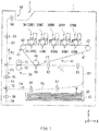
- FIG. 1 illustrates an example of a planar configuration of the image forming apparatus.
- the medium M may be conveyed along conveyance routes R1 to R5.
- Each of the conveyance routes R1 to R5 is illustrated by a dashed line in FIG. 1 .
- the image forming apparatus may include, inside a housing 1, a tray 10, a feeding roller 20, one or more developing units 30, a transferring unit 40, a fixing unit 50, conveying rollers 61 to 68, and conveyance path switching guides 71 and 72, for example.
- the housing 1 may include one or more types of materials such as a metal material and a polymer material, for example.
- the housing 1 may be provided with a stacker 2 to which the medium M provided with a formed image is to be discharged.
- the medium M provided with the formed image may be discharged from a discharge opening 1 H provided in the housing 1.
- the tray 10 may be attached detachably to the housing 1, for example.
- the tray 10 may contain the medium M.
- the feeding roller 20 may extend in a Y-axis direction and be rotatable around the Y-axis, for example.
- Each of the members referred to by the name including the term "roller" out of a series of members described below may extend in the Y-axis direction and be rotatable around the Y-axis, as with the feeding roller 20.
- the tray 10 may contain a plurality of media M in a stacked state, for example.
- the media M contained in the tray 10 may be picked out one by one from the tray 10 by the feeding roller 20, for example.
- Each of the number of the tray 10 and the number of the feeding roller 20 is not particularly limited, and may be only one or two or more.
- FIG. 1 illustrates an example case in which one tray 10 and one feeding roller 20 are provided.
- the one or more developing units 30 each perform an attachment process of a toner, i.e., a development process, with the use of the toner.
- the attachment process is a process of attaching the toner.
- the one or more developing units 30 each may form a latent image and attach the toner to the formed latent image by utilizing Coulomb force.
- the latent image may be an electrostatic latent image, for example.
- the image forming apparatus may include five developing units 30, for example.
- the five developing units 30 may include one developing unit 30 (30K) that performs the development process with the use of the non-luminescent toner, and four developing units 30 (30NC, 30NM, 30NY, and 30NW) that each perform the development process with the use of the luminescent toner, for example.
- the developing units 30K, 30NC, 30NM, 30NY, and 30NW each may be attached detachably to the housing 1, and may be disposed along a traveling path of an intermediate transfer belt 41 which will be described later in greater detail, for example.
- the developing units 30K, 30NC, 30NM, 30NY, and 30NW may be disposed in order from the upstream toward the downstream in a traveling direction, illustrated by an arrow F5, in which the intermediate transfer belt 41 travels, for example.
- the developing units 30K, 30NC, 30NM, 30NY, and 30NW may have similar configurations except for having toners different in type (color) from each other, for example.
- the toners each may be contained in a cartridge 38 which will be described later in greater detail referring to FIG. 2 .
- the configuration of each of the developing units 30K, 30NC, 30NM, 30NY, and 30NW will be described later in greater detail.
- the transferring unit 40 performs the transfer process with the use of the toners that have been subjected to the development process by the respective developing units 30. Specifically, the transferring unit 40 may transfer, onto the medium M, the toner attached to the electrostatic latent image by each of the developing units 30.
- the transfer process described in this example may include the primary transfer process and the secondary transfer process as described above, for example.
- the transferring unit 40 may include the intermediate transfer belt 41, a driving roller 42, a driven roller (an idle roller) 43, a backup roller 44, one or more primary transfer rollers 45, a secondary transfer roller 46, and a cleaning blade 47, for example.
- the intermediate transfer belt 41 may be a medium (an intermediate transfer medium) onto which the toner is temporarily transferred before the toner is transferred onto the medium M.
- the intermediate transfer belt 41 may be an elastic endless belt, for example.
- the intermediate transfer belt 41 may include one or more of polymer materials such as polyimide.
- the intermediate transfer belt 41 may be movable in response to rotation of the driving roller 42 while lying on the driving roller 42, the driven roller 43, and the backup roller 44.
- the driving roller 42 may be rotatable with a drive source such as a motor.
- a drive source such as a motor.
- Each of the driven roller 43 and the backup roller 44 may be rotatable in response to the rotation of the driving roller 42, for example.
- the one or more primary transfer rollers 45 each may transfer the toner attached to the electrostatic latent image onto the intermediate transfer belt 41. In other words, the one or more primary transfer rollers 45 each may perform primary transfer.
- the one or more primary transfer rollers 45 each may be so pressed against the corresponding developing unit 30 as to be in contact with the corresponding developing unit 30 with the intermediate transfer belt 41 in between.
- the one or more primary transfer rollers 45 each may be so pressed against a photosensitive drum 31 in the corresponding developing unit 30 as to be in contact with the photosensitive drum 31 with the intermediate transfer belt 41 in between.
- the photosensitive drum 31 will be described later in greater detail referring to FIG. 2 .
- the one or more primary transfer rollers 45 each may be rotatable in accordance with the traveling of the intermediate transfer belt 41.
- the transferring unit 40 may include five primary transfer rollers 45, i.e., primary transfer rollers 45K, 45NC, 45NM, 45NY, and 45NW, corresponding to the five developing units 30, i.e., the developing units 30K, 30NC, 30NM, 30NY, and 30NW, for example.
- the transferring unit 40 may also include one secondary transfer roller 46 corresponding to the one backup roller 44.
- the secondary transfer roller 46 may transfer, onto the medium M, the toner that has been transferred onto the intermediate transfer belt 41. In other words, the secondary transfer roller 46 may perform secondary transfer.
- the secondary transfer roller 46 may be so pressed against the backup roller 44 as to be in contact with the backup roller 44.
- the secondary transfer roller 46 may include a core member and an elastic layer, for example.
- the core member may include metal, for example.
- the elastic layer may include a foamed rubber layer that covers an outer peripheral surface of the core member, for example.
- the secondary transfer roller 46 may be rotatable in accordance with the traveling of the intermediate transfer belt 41.
- the cleaning blade 47 may be so pressed against the intermediate transfer belt 41 as to be in contact with the intermediate transfer belt 41.
- the cleaning blade 47 may scrape off unnecessary remains of the toner on the surface of the intermediate transfer belt 41.
- the fixing unit 50 performs the fixing process with the use of the toner that has been transferred onto the medium M by the transferring unit 40. Specifically, the fixing unit 50 may apply pressure on the toner that has been transferred onto the medium M by the transferring unit 40 while applying heat to the toner. The fixing unit 50 may thus fix the toner onto the medium M.
- the fixing unit 50 may include a heating roller 51 and a pressurizing roller 52, for example.
- the heating roller 51 may apply heat to the toner.
- the heating roller 51 may include a metal core and a resin coating, for example.
- the metal core may have a hollow cylindrical shape, for example.
- the resin coating may cover the surface of the metal core.
- the metal core may include one or more of metal materials such as aluminum, for example.
- the resin coating may include one or more of polymer materials such as a copolymer of tetrafluoroethylene and perfluoroalkylvinylether (PFA) and polytetrafluoroethylene (PTFE), for example.
- PFA perfluoroalkylvinylether
- PTFE polytetrafluoroethylene
- a heater may be provided inside the metal core of the heating roller 51, for example.
- Non-limiting examples of the heater may include a halogen lamp.
- the surface temperature of the heating roller 51 may be detected by a thermistor that is provided at a position away from the heating roller 51, for example.
- the pressurizing roller 52 may be so pressed against the heating roller 51 as to be in contact with the heating roller 51.
- the pressurizing roller 52 may apply a pressure to the toner.
- the pressurizing roller 52 may be a metal rod, for example.
- the metal rod may include one or more of metal materials such as aluminum, for example.
- Each of the conveying rollers 61 to 68 may include a pair of rollers that face each other with corresponding one of the conveyance routes R1 to R5 of the medium M in between. Each of the conveying rollers 61 to 68 may convey the medium M that has been taken out by the feeding rollers 20.
- the medium M may be conveyed by the conveying rollers 61 to 64 along the conveyance routes R1 and R2. In another example case where luminescent images are to be formed on both surfaces of the medium M, the medium M may be conveyed by the conveying rollers 61 to 68 along the conveyance routes R1 to R5.
- the conveyance path switching guides 71 and 72 each may switch a conveyance direction, of the medium M, in which the medium M is to be conveyed, depending on conditions such as a manner in which a luminescent image is formed on the medium M.
- the conditions on the manner in which a luminescent image is formed on the medium M may include whether the luminescent image is to be formed only on one surface of the medium M and whether the luminescent images are to be formed on both surfaces of the medium M, for example.
- the image forming apparatus may include one or more components other than the components described above, for example.
- the components other than the components described above are not particularly limited.
- non-limiting examples of such components may include a controller that controls an overall operation of the image forming apparatus, and an operation panel that is usable by a user to operate the image forming apparatus.
- This controller may include an electronic circuit such as a central processing unit (CPU), and control the series of processes (operations) of the image forming apparatus including the development process, the transfer process, and the fixing process described above.
- CPU central processing unit
- FIG. 2 enlarges the example of the planar configuration of the developing unit 30 illustrated in FIG. 1 .
- the developing units 30K, 30NC, 30NW, 30NY, and 30NW each may include the photosensitive drum 31, a charging roller 32, a developing roller 33, a feeding roller 34, a developing blade 35, a cleaning blade 36, a light-emitting diode (LED) head 37, and the cartridge 38, for example.
- the photosensitive drum 31 may be an organic photoreceptor that includes a cylindrical electrically-conductive supporting body and a photoconductive layer, for example.
- the photoconductive layer may cover an outer peripheral surface of the electrically-conductive supporting body.
- the photosensitive drum 31 may be rotatable with a drive source such as a motor.
- the electrically-conductive supporting body may be a metal pipe that includes one or more of metal materials such as aluminum, for example.
- the photoconductive layer may be a stack that includes an electric charge generating layer and an electric charge transfer layer, for example.
- the charging roller 32 may include a metal shaft and an electrically-semiconductive epichlorohydrin rubber layer that covers an outer peripheral surface of the metal shaft, for example.
- the charging roller 32 may be so pressed against the photosensitive drum 31 as to be in contact with the photosensitive drum 31, thereby charging the photosensitive drum 31.
- the developing roller 33 may include a metal shaft and an electrically-semiconductive urethane rubber layer that covers an outer peripheral surface of the metal shaft, for example.
- the developing roller 33 may support the toner that is fed from the feeding roller 34, and attach the fed toner onto the electrostatic latent image formed on the surface of the photosensitive drum 31.
- the feeding roller 34 may include a metal shaft and an electrically-semiconductive foamed silicone sponge layer that covers an outer peripheral surface of the metal shaft, for example.
- the feeding roller 34 may feed the luminescent toner to the surface of the photosensitive drum 31 while being in contact with the developing roller 33 in a slidable manner.
- the developing blade 35 may control the thickness of the toner fed on the surface of the feeding roller 34.
- the developing blade 35 may be disposed at a position away from the developing roller 33 with a predetermined spacing in between.
- the thickness of the toner may be controlled on the basis of the spacing between the developing roller 33 and the developing blade 35.
- the developing blade 35 may include one or more of metal materials such as stainless steel, for example.
- the cleaning blade 36 may scrape off unnecessary remains of the toner that are present on the surface of the photosensitive drum 31.
- the cleaning blade 36 may extend in a direction substantially parallel to a direction in which the photosensitive drum 31 extends, for example.
- the cleaning blade 36 may be so pressed against the photosensitive drum 31 as to be in contact with the photosensitive drum 31.
- the cleaning blade 36 may include one or more of polymer materials such as urethane rubber, for example.
- the LED head 37 may be an exposure unit that performs exposure of the surface of the photosensitive drum 31, and thereby forms an electrostatic latent image on the surface of the photosensitive drum 31.
- the LED head 37 may include an LED device and a lens array, for example.
- the LED device and the lens array may be so disposed that light (application light) outputted from the LED device is imaged on the surface of the photosensitive drum 31.
- the cartridge 38 may be attached detachably, for example.
- the cartridge 38 may contain a toner.
- the type, specifically, the color, of the toner contained in the cartridge 38 may be as described below, for example.
- the luminescent toner may be a fluorescent toner that generates fluorescent light in response to application of light such as ultraviolet light, for example.
- the cartridge 38 of the developing unit 30NC may contain a fluorescent cyan toner that is the luminescent toner, for example.
- the cartridge 38 of the developing unit 30NM may contain a fluorescent magenta toner that is the luminescent toner, for example.
- the cartridge 38 of the developing unit 30NY may contain a fluorescent yellow toner that is the luminescent toner, for example.
- the cartridge 38 of the developing unit 30NW may contain a fluorescent white toner that is the luminescent toner, for example.
- the cartridge 38 of the developing unit 30K may contain a black toner that is a non-luminescent toner, for example.
- the luminescent toner may be used to form the luminescent image.
- one or more of the fluorescent cyan toner, the fluorescent magenta toner, the fluorescent yellow toner, and the fluorescent white toner may be used in a case of forming the luminescent image, for example.
- both the luminescent toner and the non-luminescent toner may be used to form the luminescent image.
- the black toner may be used together with the one or more of the fluorescent cyan toner, the fluorescent magenta toner, the fluorescent yellow toner, and the fluorescent white toner in a case of forming the luminescent image, for example.
- five types of toners may be used as described above, for example.
- four types of luminescent toners and one type of non-luminescent toner may be used.
- the four types of luminescent toners may be the fluorescent cyan toner, the fluorescent magenta toner, the fluorescent yellow toner, and the fluorescent white toner.
- the one type of non-luminescent toner may be the black toner.
- the toners described below may be of a single component development method, for example. More specifically, the toners described below may be negatively-charged.
- the single component development method provides a toner itself with an appropriate amount of electric charge without using a carrier (a magnetic particle) to apply an electric charge to the toner.
- a two component development method provides a toner with an appropriate amount of electric charge by utilizing friction between the foregoing carrier and the toner owing to mixing of the foregoing carrier and the toner.
- the fluorescent cyan toner may include a cyan coloring agent and a fluorescent whitener, for example. It is to be noted that the fluorescent cyan toner may include one or more other materials together with the cyan coloring agent and the fluorescent whitener.
- the cyan coloring agent may include one or more of materials such as a cyan pigment and a cyan dye, for example.
- Non-limiting examples of the cyan pigment may include phthalocyanine blue such as C.I. Pigment Blue 15:3.
- Non-limiting examples of the cyan dye may include Pigment Blue 15:3.
- the content of the cyan coloring agent is not particularly limited. However, for example, the content of the cyan coloring agent may be about 2 parts by weight to about 25 parts by weight with respect to the content (100 parts by weight) of a binder which will be described later in greater detail. Preferably, the content of the cyan coloring agent may be about 2 parts by weight to about 15 parts by weight with respect to the content of the binder.
- the fluorescent whitener may include one or more of materials such as a stilbene-based compound, a coumarin-based compound, and a biphenyl-based compound, for example.
- the content of the fluorescent whitener is not particularly limited. However, for example, the content of the fluorescent whitener may be about 2 parts by weight to about 25 parts by weight with respect to the content (100 parts by weight) of the binder which will be described later in greater detail. Preferably, the content of the fluorescent whitener may be about 2 parts by weight to about 15 parts by weight with respect to the content of the binder.
- the types of the materials other than the cyan coloring agent and the fluorescent whitener are not particularly limited.
- Non-limiting examples of the materials other than the cyan coloring agent and the fluorescent whitener may include the binder, an external additive, a release agent, and an electric charge control agent.
- the binder may mainly bind materials such as the fluorescent cyan coloring agents with each other.
- the binder may include one or more of polymer compounds such as polyester-based resin, styrene-acrylic-based resin, epoxy-based resin, and styrene-butadiene-based resin.
- the binder may preferably include the polyester-based resin.
- the polyester-based resin has high affinity for the medium M such as paper, and the toner including the polyester-based resin as the binder is therefore easily fixed to the medium M.
- the polyester-based resin has high physical strength even with a relatively-small molecular weight, and the toner including the polyester-based resin as the binder therefore has high durability.
- Non-limiting examples of the polyester-based resin may include a reactant (a condensation polymer) of one or more alcohols and one or more carboxylic acids.
- the type of the alcohol is not particularly limited.
- the alcohol may be preferably an alcohol having a valence of two or greater or a derivative thereof, for example.
- Non-limiting examples of the alcohol having the valence of two or greater may include ethylene glycol, diethylene glycol, triethylene glycol, polyethylene glycol, propylene glycol, butanediol, pentanediol, hexanediol, cyclohexanedimethanol, xylene glycol, dipropylene glycol, polypropylene glycol, bisphenol A, hydrogenated bisphenol A, bisphenol A ethylene oxide, bisphenol A propylene oxide, sorbitol, and glycerin.
- the type of the carboxylic acid is not particularly limited.
- the carboxylic acid may be preferably a carboxylic acid having a valence of two or greater or a derivative thereof, for example.
- Non-limiting examples of the carboxylic acid having the valence of two or greater may include maleic acid, fumaric acid, phthalic acid, isophthalic acid, terephthalic acid, succinic acid, adipic acid, trimellitic acid, pyromellitic acid, cyclopentane dicarboxylic acid, succinic anhydride, trimellitic anhydride, maleic anhydride, and dodecenylsuccinic anhydride.
- the external additive may mainly suppress a phenomenon such as aggregation of the fluorescent cyan toner, and thereby improve fluidity of the fluorescent cyan toner.
- the external additive may include one or more of inorganic materials and organic materials.
- Non-limiting examples of the inorganic material may include hydrophobic silica.
- Non-limiting examples of the organic material may include melamine resin.
- the content of the external additive is not particularly limited. However, for example, the content of the external additive may be from about 0.01 parts by weight to about 10 parts by weight with respect to the conteent of the binder (100 parts by weight), and may be preferably from about 0.05 parts by weight to about 8 parts by weight with respect to the content of the binder.
- the release agent may mainly improve characteristics, of the fluorescent cyan toner, such as fixing characteristics and offset resistance.
- the release agent may include one or more of waxes such as aliphatic-hydrocarbon-based wax, an oxide of aliphatic-hydrocarbon-based wax, fatty-acid-ester-based wax, and a deoxide of fatty-acid-ester-based wax.
- the release agent may also be a block copolymer of any of the foregoing series of waxes.
- the content of the release agent is not particularly limited.
- the content of the release agent may be from about 0.1 parts by weight to about 20 parts by weight with respect to the content (100 parts by weight) of the binder, and may be preferably from about 0.5 parts by weight to about 12 parts by weight with respect to the content of the binder.
- Non-limiting examples of the aliphatic-hydrocarbon-based wax may include low-molecular polyethylene, low-molecular polypropylene, a copolymer of olefin, microcrystalline wax, paraffin wax, and Fischer-Tropsch wax.
- Non-limiting examples of the oxide of aliphatic-hydrocarbon-based wax may include oxidized polyethylene wax.
- Non-limiting examples of the fatty-acid-ester-based wax may include carnauba wax and montanic acid ester wax.
- the deoxide of fatty-acid-ester-based wax may be partially-deoxidized or fully-deoxidized fatty-acid-ester-based wax.
- Non-limiting examples of the deoxide of fatty-acid-ester-based wax may include deoxidized carnauba wax.
- the electric charge control agent may mainly control characteristics such as triboelectric charging characteristics of the fluorescent cyan toner.
- the electric charge control agent to be used for the negatively-charged toner may include one or more of materials such as an azo-based complex, a salicylic-acid-based complex, and a calixarene-based complex, for example.
- the content of the electric charge control agent is not particularly limited. However, the content of the electric charge control agent may be from about 0.05 parts by weight from about 15 parts by weight with respect to the content (100 parts by weight) of the binder, for example.
- the fluorescent magenta toner may have a configuration almost similar to the configuration of the fluorescent cyan toner except that the fluorescent magenta toner includes one or both of a magenta coloring agent and a fluorescent magenta coloring agent instead of the cyan coloring agent, for example.
- the magenta coloring agent may include one or more of materials such as a magenta pigment and a magenta dye, for example.
- a magenta pigment may include quinacridone.
- magenta dye may include C.I. Pigment Red 238.
- the fluorescent magenta coloring agent that is the fluorescent coloring agent may include one or more of materials such as a fluorescent magenta pigment and a fluorescent magenta dye.
- Non-limiting examples of the fluorescent magenta coloring agent may include a fluorescent coloring agent such as SX-100 series and SX-1000 series available from Sinloihi Co., Ltd, located in Kanagawa, Japan.
- the fluorescent magenta toner When the fluorescent magenta toner includes the fluorescent magenta coloring agent, fluorescent characteristics are exhibited by the included fluorescent magenta coloring agent.
- the fluorescent magenta toner may therefore not necessarily include the fluorescent whitener.
- the fluorescent magenta toner when the fluorescent magenta toner includes the magenta coloring agent, the fluorescent magenta toner may so include the fluorescent whitener as to secure the fluorescent characteristics.
- the fluorescent yellow toner may have a configuration almost similar to the configuration of the fluorescent cyan toner except that the fluorescent yellow toner includes one or both of a yellow coloring agent and a fluorescent yellow coloring agent instead of the cyan coloring agent, for example.
- the yellow coloring agent may include one or more of materials such as a yellow pigment and a yellow dye.
- Non-limiting examples of the yellow pigment may include Pigment Yellow 74.
- Non-limiting examples of the yellow dye may include C.I. Pigment Yellow 74 and cadmium yellow.
- the fluorescent yellow coloring agent that is the fluorescent coloring agent may include one or more of materials such as a fluorescent yellow pigment and a fluorescent yellow dye, for example.
- Non-limiting examples of the fluorescent yellow coloring agent may include a fluorescent coloring agent such as SX-100 series and SX-1000 series available from Sinloihi Co., Ltd, Located in Kanagawa, Japan.
- the fluorescent yellow toner includes the fluorescent yellow coloring agent
- fluorescent characteristics are exhibited by the included fluorescent yellow coloring agent.
- the fluorescent yellow toner may therefore not necessarily include the fluorescent whitener.
- the fluorescent yellow toner may so include the fluorescent whitener as to secure the fluorescent characteristics.
- the fluorescent white toner may have a configuration similar to the configuration of the fluorescent cyan toner except that the fluorescent white toner includes a white coloring agent instead of the cyan coloring agent, for example.
- the white coloring agent may include one or more of materials such as a white pigment, for example.
- a white pigment may include titanium oxide.
- the black toner may have a configuration similar to the configuration of the fluorescent cyan toner except that the black toner includes a black coloring agent instead of the cyan coloring agent and does not include the fluorescent whitener, for example.
- the black coloring agent may include one or more of materials such as a black pigment and a black dye, for example.
- Non-limiting examples of the black pigment may include carbon.
- Non-limiting examples of the black dye may include carbon black.
- Non-limiting examples of the carbon black may include furnace black and channel black.
- a method of manufacturing the toners is not particularly limited.
- the method of manufacturing the toners may be pulverization, polymerization, or any other method, for example.
- the foregoing methods may be used in any combination.
- Non-limiting examples of the polymerization may include suspension polymerization.
- FIG. 3 illustrates an example of a flow for describing an operation of the image forming apparatus.
- FIGs. 4 to 6 each illustrate an example of a cross-sectional configuration of the medium M for describing a configuration of an image to be formed by the image forming apparatus.
- the image forming apparatus performs the image forming operation in the regular mode or the light resistance enhancement mode
- the light resistance enhancement mode involves two modes having respective levels that are different from each other, i.e., a light resistance enhancement mode 1 and a light resistance enhancement mode 2.
- the number of step in parentheses in the description below corresponds to the number of step illustrated in FIG. 3 .
- a user Before formation of an image, a user may select whether to use the light resistance enhancement mode as the image formation mode by operating the operation panel provided on the image forming apparatus, for example (step S101).
- the image forming apparatus may perform an image forming operation in the regular mode on the basis of the image data D (step S102), and thereby form the luminescent image (step S103).
- the image data D may be directed to the formation of the luminescent image by the image forming apparatus.
- the image data D may be supplied to the image forming apparatus, for example, from an external terminal device.
- the external terminal device may include a personal computer that is usable by the user of the image forming apparatus.
- the image forming apparatus may perform the image forming process once with the use of the luminescent toner on the basis of the image data D, and perform a cleaning process on an as-necessary basis, as will be described below.
- the image forming process may include the development process, the primary transfer process, the secondary transfer process, and the fixing process.
- the medium M contained in the tray 10 may be picked up by the feeding roller 20.
- the medium M picked up by the feeding roller 20 may be conveyed by the conveying rollers 61 and 62 along the conveyance route R1 in a direction indicated by an arrow F1.
- the development process may involve the operation performed in the developing unit 30NC as described below.
- the charging roller 32 may apply a direct-current voltage to the surface of the photosensitive drum 31 while rotating in accordance with the rotation of the photosensitive drum 31.
- the surface of the photosensitive drum 31 may be thereby charged evenly.
- the LED head 37 may apply light to the surface of the photosensitive drum 31 on the basis of the image data D.
- a surface potential in a part, of the surface of the photosensitive drum 31, on which the light is applied is thereby attenuated.
- optical attenuation occurs in the part, of the surface of the photosensitive drum 31, on which the light is applied.
- An electrostatic latent image may be thus formed on the surface of the photosensitive drum 31.
- a luminescent toner NT specifically, the fluorescent cyan toner, contained in the cartridge 38 may be released toward the feeding roller 34.
- the feeding roller 34 may rotate after receiving application of a voltage.
- the fluorescent cyan toner may be thus fed from the cartridge 38 onto the surface of the feeding roller 34.
- the developing roller 33 may rotate while being so pressed against the feeding roller 34 as to be in contact with the feeding roller 34, after receiving application of a voltage.
- the fluorescent cyan toner fed onto the surface of the feeding roller 34 may be thereby adsorbed onto the surface of the developing roller 33, whereby the fluorescent cyan toner may be conveyed by utilizing the rotation of the developing roller 33.
- the fluorescent cyan toner adsorbed onto the surface of the developing roller 33 may be partially removed by the developing blade 35, whereby the fluorescent cyan toner adsorbed onto the surface of the developing roller 33 may be caused to have an even thickness.
- the fluorescent cyan toner adsorbed onto the surface of the developing roller 33 may be transferred onto the surface of the photosensitive drum 31.
- the fluorescent cyan toner may be thereby attached to the surface of the photosensitive drum 31, i.e., the electrostatic latent image.
- the driven roller 43 and the backup roller 44 may rotate in response to the rotation of the driving roller 42. This may cause the intermediate transfer belt 41 to travel in a direction indicated by an arrow F5.
- the primary transfer process may involve application of a voltage to the primary transfer roller 45NC.
- the primary transfer roller 45NC may be so pressed against the photosensitive drum 31 as to be in contact with the photosensitive drum 31 with the intermediate transfer belt 41 in between.
- the fluorescent cyan toner that has been attached to the surface, i.e., the electrostatic latent image of the photosensitive drum 31 in the foregoing development process may be transferred onto the intermediate transfer belt 41.
- the intermediate transfer belt 41 onto which the fluorescent cyan toner has been transferred may continue to travel in the direction indicated by the arrow F5. This may allow each of the set of the developing unit 30NM and the primary transfer roller 45NM, the set of the developing unit 30NY and the primary transfer roller 45NY, and the set of the developing unit 30NW and the primary transfer roller 45W to perform the development process and the primary transfer process in order by a procedure similar to the foregoing procedure performed by the developing unit 30NC and the primary transfer roller 45NC.
- the developing unit 30NM and the primary transfer roller 45NM may transfer the fluorescent magenta toner onto the surface of the intermediate transfer belt 41. Thereafter, the developing unit 30NY and the primary transfer roller 45NY may transfer the fluorescent yellow toner onto the surface of the intermediate transfer belt 41. Thereafter, the developing unit 30NW and the primary transfer roller 45NW may transfer the fluorescent white toner onto the surface of the intermediate transfer belt 41.
- each of the development process and the primary transfer process is actually performed by the respective developing units 30NC, 30NM, 30NY, and 30NW and the primary transfer rollers 45NC, 45NM, 45NY, and 45NW may be determined depending on the color or the combination of colors that is necessary for forming the luminescent image.
- the medium M may pass between the backup roller 44 and the secondary transfer roller 46 upon being conveyed along the conveyance route R1.
- the secondary transfer process may involve application of a voltage to the secondary transfer roller 46.
- the secondary transfer roller 46 may be so pressed against the backup roller 44 as to be in contact with the backup roller 44 with the medium M in between.
- the luminescent toner NT that has been transferred onto the intermediate transfer belt 41 in the foregoing primary transfer process may be transferred onto the medium M.
- the medium M may be continuously conveyed along the conveyance route R1 in the direction indicated by the arrow F1.
- the medium M may be thus conveyed to the fixing unit 50.
- the fixing process may involve a control that is so performed as to cause the surface temperature of the heating roller 51 to be a predetermined temperature.
- the pressurizing roller 52 rotates while being so pressed against the heating roller 51 as to be in contact with the heating roller 51, the medium M may be so conveyed as to pass between the heating roller 51 and the pressurizing roller 52.
- the luminescent toner NT that has been transferred onto the surface of the medium M may be thereby applied with heat, which may cause the luminescent toner NT to be molten. Further, the molten luminescent toner NT may be so pressed against the medium M as to be in contact with the medium M. This may allow the luminescent toner NT to be firmly attached to the medium M.
- the luminescent toner NT may be so fixed to a specific region on the surface of the medium M as to have a specific pattern on the basis of the image data D as illustrated in FIG. 4 .
- the luminescent image may be thus formed.
- the medium M on which the luminescent image has been formed may be conveyed by the conveying rollers 63 and 64 along the conveyance route R2 in a direction indicated by an arrow F2.
- the medium M may thus be discharged from the discharge opening 1 H to the stacker 2.
- the procedure of conveying the medium M may be varied in accordance with the manner by which the luminescent image is to be formed on the surface of the medium M.
- the medium M that has passed the fixing unit 50 may be conveyed by the conveying rollers 65 to 68 along the conveyance routes R3 to R5 in directions indicated by respective arrows F3 and F4, and be thereafter conveyed again by the conveying rollers 61 and 62 along the conveyance route R1 in the direction indicated by the arrow F1.
- the direction in which the medium M is to be conveyed may be controlled by the conveyance path switching guides 71 and 72. This may allow the back surface of the medium M to be subjected to the image forming process including the development process, the primary transfer process, the secondary transfer process, and the fixing process.
- the back surface of the medium M is a surface, of the medium M, on which an image is not yet formed.
- Unnecessary remains of the luminescent toner NT may sometimes be present on the surface of the photosensitive drum 31 in each of the developing units 30NC, 30NM, 30NY, and 30NW.
- the unnecessary remains of the luminescent toner NT may be part of the luminescent toner NT that has been used in the primary transfer process, which may be the luminescent toner NT that has remained on the surface of the photosensitive drum 31 without being transferred onto the intermediate transfer belt 41, for example.
- the photosensitive drum 31 may rotate while being so pressed against the cleaning blade 36 as to be in contact with the cleaning blade 36 in each of the developing units 30NC, 30NM, 30NY, and 30NW. This may cause the remains of the luminescent toner NT present on the surface of the photosensitive drum 31 to be scraped off by the cleaning blade 36. As a result, the unnecessary remains of the luminescent toner NT may be removed from the surface of the photosensitive drum 31.
- part of the luminescent toner NT that has been transferred onto the surface of the intermediate transfer belt 41 in the primary transfer process may sometimes not be transferred onto the surface of the medium M in the secondary transfer process and may remain on the surface of the intermediate transfer belt 41.
- the cleaning blade 47 may scrape off the remains of the luminescent toner NT present on the surface of the intermediate transfer belt 41 in the transferring unit 40 upon traveling of the intermediate transfer belt 41 in the direction indicated by the arrow F5. As a result, unnecessary remains of the luminescent toner NT may be removed from the surface of the intermediate transfer belt 41.
- the image forming operation of the image forming apparatus may be thus completed in the case in which the regular mode is selected by the user.
- step S101: Y when the user selects the light resistance enhancement mode (step S101: Y), the user may further select whether to use the light resistance enhancement mode 1, for example, by further operating the operation panel (step S104).
- the user may be able to select one of the two light resistance enhancement modes having respective levels that are different from each other, i.e., the light resistance enhancement modes 1 and 2 as described above.
- the light resistance enhancement mode 1 may be an image formation mode that achieves light resistance greater than that in the regular mode.
- the light resistance enhancement mode 2 may be an image formation mode that achieves light resistance greater than that in the light resistance enhancement mode 1.
- the image forming apparatus may perform an image forming operation in the light resistance enhancement mode 1 on the basis of the image data D (steps S105 and S106), and thereby form the luminescent image (step S103).
- the image forming apparatus may perform the image forming process twice, and perform the cleaning process on an as-necessary basis, as will be described below in greater detail.
- the image forming process for one time may involve a series of processes including the development process, the primary transfer process, the secondary transfer process, and the fixing process, for example.
- the image forming apparatus may first perform the image forming process for the first time by performing the development process, the primary transfer process, the secondary transfer process, and the fixing process, on the basis of the image data D. This may allow a first layer of the luminescent toner NT to be so fixed to a specific region on the surface of the medium M as to have a specific pattern on the basis of the image data D as illustrated in FIG 5 .
- the image forming apparatus may perform the image forming process for the second time by performing again the development process, the primary transfer process, the secondary transfer process, and the fixing process, on the basis of the image data D.
- This may allow a second layer of the luminescent toner NT to be so fixed to the specific region on the surface of the medium M as to have the specific pattern on the basis of the image data D as illustrated in FIG. 5 .
- the content of the image forming process including the development process, the primary transfer process, the secondary transfer process, the fixing process, and the cleaning process, that is performed twice in the light resistance enhancement mode 1 may be similar to or the same as the content of the image forming process, including the development process, the primary transfer process, the secondary transfer process, the fixing process, and the cleaning process, that is performed in the foregoing regular mode.
- two layers of the luminescent toner NT may be fixed to the medium M, and the luminescent image may be thereby formed.
- each of the first layer of the luminescent toner NT and the second layer of the luminescent toner NT may be fixed to the medium M on the basis of the image data D.
- This may allow the surface of the medium M to be provided with the second layer of the luminescent toner NT, having the pattern same as the pattern of the first layer of the luminescent toner NT, that is fixed to a region same as the region in which the first layer of the luminescent toner NT has been already fixed to.
- the second layer of the luminescent toner NT may be thus so disposed as to almost overlap the first layer of the luminescent toner NT.
- the first layer of the luminescent toner NT and the second layer of the luminescent toner NT may almost overlap each other. Therefore, the luminescent image formed with the first layer of the luminescent toner NT and the luminescent image formed with the second layer of the luminescent toner NT may almost overlap each other. In other words, two luminescent images having the same pattern may be formed in the same region on the medium M, whereby the two luminescent images may be caused to overlap each other.
- two luminescent images are formed in the same region may refer to that the two luminescent images are formed on the basis of the same image data D. Accordingly, as long as the two luminescent images are formed on the basis of the same image data D, the region in which one of the luminescent images is formed and the region in which the other of the luminescent images is formed are not necessarily the same in a precise sense, and may be slightly shifted from each other due to any reason.
- the medium M that has passed the fixing unit 50 may be conveyed by the conveying rollers 65 to 67 along the conveyance routes R3 and R5 in the directions indicated by the arrows F3 and F4, and be thereafter conveyed by the conveying rollers 61 and 62 along the conveyance route R1 again in the direction indicated by the arrow F1.
- the direction in which the medium M is to be conveyed may be controlled by the conveyance path switching guides 71 and 72. This allows the single surface of the medium M to be repeatedly subjected to the foregoing image forming process.
- the image forming apparatus may perform an image forming operation in the light resistance enhancement mode 2 on the basis of the image data D (steps S107, S108, and S109), and thereby form the luminescent image (step S103).
- the image forming apparatus may perform the image forming process three times, and perform the cleaning process on an as-necessary basis, as will be described below.
- the image forming process for one time may involve a series of processes including the development process, the primary transfer process, the secondary transfer process, and the fixing process, for example.
- the image forming apparatus may first perform the image forming process for the first time by performing the development process, the primary transfer process, the secondary transfer process, and the fixing process, on the basis of the image data D. This may allow a first layer of the luminescent toner NT to be so fixed to a specific region on the surface of the medium M as to have a specific pattern on the basis of the image data D as illustrated in FIG. 6 .
- the image forming apparatus may perform the image forming process for the second time by performing again the development process, the primary transfer process, the secondary transfer process, and the fixing process, on the basis of the image data D.
- This may allow a second layer of the luminescent toner NT to be so fixed to the specific region on the surface of the medium M as to have the specific pattern on the basis of the image data D as illustrated in FIG. 6 .
- the image forming apparatus may perform the image forming process for the third time by further performing the development process, the primary transfer process, the secondary transfer process, and the fixing process again on the basis of the image data D.
- This may allow a third layer of the luminescent toner NT to be so fixed to the specific region on the surface of the medium M as to have the specific pattern on the basis of the image data D as illustrated in FIG. 6 .
- the content of the image forming process including the development process, the primary transfer process, the secondary transfer process, the fixing process, and the cleaning process, that is performed three times in the light resistance enhancement mode 2 may be similar to or the same as the content of the image forming process, including the development process, the primary transfer process, the secondary transfer process, the fixing process, and the cleaning process, that is performed in the foregoing regular mode.
- three layers of the luminescent toner NT may be fixed to the medium M, and the luminescent image may be thereby formed.
- each of the first layer of the luminescent toner NT, the second layer of the luminescent toner NT, and the third layer of the luminescent toner NT may be fixed to the medium M on the basis of the image data D.
- This may allow the surface of the medium M to be provided with the second layer of the luminescent toner NT, having the pattern same as the pattern of the first layer of the luminescent toner NT, that is fixed to a region same as the region in which the first layer of the luminescent toner NT has been already fixed to.
- the second layer of the luminescent toner NT may be thus so disposed as to almost overlap the first layer of the luminescent toner NT.
- the surface of the medium M to be provided with the third layer of the luminescent toner NT, having the pattern same as the pattern of the first and second layers of the luminescent toner NT, that is fixed to a region same as the region in which the first and second layers of the luminescent toner NT have been already fixed to.
- the third layer of the luminescent toner NT may be thus so disposed as to almost overlap the first and second layers of the luminescent toner NT. Accordingly, the first layer of the luminescent toner NT, the second layer of the luminescent toner NT, and the third layer of the luminescent toner NT may almost overlap each other.
- the luminescent image formed with the first layer of the luminescent toner NT, the luminescent image formed with the second layer of the luminescent toner NT, and the luminescent image formed with the third layer of the luminescent toner NT may almost overlap each other.
- three luminescent images having the same pattern may be formed in the same region on the medium M, whereby the three luminescent images may be caused to overlap each other.
- three luminescent images are formed in the same region may refer to that the three luminescent images are formed on the basis of the same image data D. Accordingly, as long as the three luminescent images are formed on the basis of the same image data D, the region in which the first one of the luminescent images is formed, the region in which the second one of the luminescent images is formed, and the region in which the third one of the luminescent images is formed are not necessarily the same in a precise sense, and may be slightly shifted from each other due to any reason.
- the medium M that has passed the fixing unit 50 may be conveyed by the conveying rollers 65 to 67 along the conveyance routes R3 and R5 in the directions indicated by the arrows F3 and F4, and be thereafter conveyed by the conveying rollers 61 and 62 along the conveyance route R1 again in the direction indicated by the arrow F1, in a manner similar to or the same as the manner in which the luminescent images are formed in the foregoing light resistance enhancement mode 1.
- the image forming apparatus may perform, for the medium M, the image forming process plural times on the basis of the image data D, and thereby form the luminescent image on the surface of the medium M.
- the image forming process may include the development process, the primary transfer process, the secondary transfer process, and the fixing process. It is therefore possible to achieve a high-quality luminescent image for the following reasons.
- the user is able to achieve a desired luminescent image having luminescent characteristics also in a case where the image forming process is performed only once for the medium M on the basis of the image data D.
- the luminescent toner NT is able to exhibit, for example, a favorable feature by the use of the luminescent characteristics as its characteristics, the color of the luminescent toner NT may fade easily.
- the absolute amount of the luminescent toner NT to be used to form the luminescent image i.e., the amount of the luminescent toner NT to be fixed to the medium M may be small.
- the fading of the color of the luminescent toner NT may easily influence the quality of the luminescent image.
- the fading of the color of the luminescent toner NT may lead to a decrease in color optical density and blurred outline, thereby making it easier to cause degradation of quality of the luminescent image.
- the absolute amount of the luminescent toner NT to be used for forming the luminescent image i.e., the amount of the fixed luminescent toner NT
- the absolute amount of the luminescent toner NT to be used for forming the luminescent image may increase.
- the fading of the color of the luminescent toner NT may be less likely to influence the quality of the luminescent image. This makes the quality of the luminescent image less likely to be degraded.
- the plurality of layers of the luminescent toner NT may be fixed to the medium M on the basis of the same image data D. Accordingly, the regions to which the respective layers of the luminescent toner NT are fixed may almost overlap each other on the surface of the medium M. In this case, the shift in color due to the shift in position between the layers of the luminescent toner NT is sufficiently suppressed. This suppresses degradation of quality of the luminescent image due to the shift in color.
- the foregoing image forming apparatus may achieve the following advantages in addition to the advantages described above.
- the fixing unit 50 may perform the fixing process of the luminescent toner NT plural times as separate processes, and thereby form the luminescent image. Specifically, in an example case where the fixing process of the luminescent toner NT is performed twice, the image forming process with the use of the luminescent toner NT including the development process, the primary transfer process, the secondary transfer process, and the fixing process may be performed for the first time, and thereafter, the image forming process with the use of the luminescent toner NT may be performed again for the second time.
- the fixing process of the luminescent toner NT for the first time may be already completed before performing the image forming process for the second time.
- the luminescent toner NT subjected to the fixing process for the first time may be therefore firmly attached to the medium M already before performing the image forming process for the second time. Accordingly, the luminescent toner NT used for the first time is less likely to adversely influence the quality of the image, compared with a case where the fixing process of the luminescent toner NT for the first time is not yet completed before performing the image forming process for the second time.
- the luminescent toner NT in a state where the fixing process of the luminescent toner NT for the first time is not yet completed, the luminescent toner NT is not firmly attached to the medium M.
- the luminescent toner NT may be therefore easily removed from the medium M.
- the luminescent toner NT may be also easily moved from a position at which the luminescent toner NT is to be fixed to another position on the medium M. This may possibly decrease the color optical density of the luminescent image and blur the outline of the luminescent image.
- the luminescent toner NT in a state where the fixing process of the luminescent toner NT for the first time is already completed, the luminescent toner NT may be firmly attached to the medium M.
- the fixing unit 50 to perform the fixing process of the luminescent toner NT plural times as separate processes, the quality of the luminescent image is further improved, thereby achieving a higher effect.
- Another advantage is that, when the luminescent toner includes one or both of the fluorescent coloring agent and the fluorescent whitener, it is possible to form a high-quality fluorescent image by utilizing luminescent characteristics of the luminescent toner to be used.
- the configuration of the image forming apparatus may be modifiable in an appropriate manner as described below.
- the fixing unit 50 may perform the fixing process of the luminescent toner NT plural times as separate processes, and thereby form the luminescent image. More specifically, in an example case where the fixing process of the luminescent toner NT is performed twice, the image forming process with the use of the luminescent toner NT including the development process, the primary transfer process, the secondary transfer process, and the fixing process may be performed for the first time, and thereafter, the image forming process with the use of the luminescent toner NT may be performed again for the second time.
- the fixing unit 50 may perform the fixing process of the luminescent toner NT plural time as a single process as long as the two layers of the luminescent toner NT are allowed to be fixed to the medium M.
- the development process and the primary transfer process with the use of the luminescent toner NT may be performed, and the development process and the primary transfer process with the use of the luminescent toner NT may be performed continuously. Thereafter, the secondary transfer process and the fixing process with the use of the foregoing luminescent toner NT may be performed.
- the second layer of the luminescent toner NT may be transferred onto the first layer of the luminescent toner NT.
- the two layers of the luminescent toner NT may thus overlap each other on the intermediate transfer belt 41.
- the two layers of the luminescent toner NT may be thereby fixed to the medium M collectively in the fixing process performed by the fixing unit 50 as a single process.
- the development process, the primary transfer process, and the secondary transfer process may be performed with the use of the luminescent toner NT, and the development process, the primary transfer process, and the secondary transfer process may be performed again continuously with the use of the luminescent toner NT.
- the fixing process may be performed with the use of the luminescent toner NT used in the two sets of the development process, the primary transfer process, and the secondary process.
- the second layer of the luminescent toner NT may be transferred onto the first layer of the luminescent toner NT.
- the two layers of the luminescent toner NT may thus overlap each other on the medium M.
- the two layers of the luminescent toner NT may be thereby fixed to the medium M collectively in the fixing process performed by the fixing unit 50 as a single process.
- the plurality of layers of the luminescent toner NT may overlap each other on the medium M. It is therefore possible to achieve a high-quality luminescent image.
- the luminescent toner NT that is not yet fixed to the medium M may tend to be easily removed from the medium M or be easily moved on the medium M as described above. It may be therefore more preferable to perform the fixing process plural times. Accordingly, it may be preferable to cause the fixing unit 50 to perform the fixing process of the luminescent toner NT plural times as separate processes, in order to improve image quality.
- the luminescent image including two or three layers of the luminescent toner NT may be formed as illustrated in FIGs. 5 and 6 by performing the image forming process for the medium M twice or three times on the basis of the image data D.
- the number of the image forming process to be performed is not particularly limited as long as the image forming process is performed twice or more.
- the image forming process may be performed four times, five times, or more.
- the absolute amount of the luminescent toner NT to be used for forming the luminescent image increases, which makes it more difficult for the quality of the luminescent image to be degraded. It is therefore possible to further improve the quality of the luminescent image.
- the five types of toners i.e., the black toner, the fluorescent cyan toner, the fluorescent magenta toner, the fluorescent yellow toner, and the fluorescent white toner, may be used.
- the types of the toners i.e., the combination of the colors of the toners, may be varied optionally.
- the fluorescent white toner may not be used and the fluorescent cyan toner, the fluorescent magenta toner, and the fluorescent yellow toner may be used as the luminescent toners.
- the luminescent toners i.e., the fluorescent cyan toner, the fluorescent magenta toner, the fluorescent yellow toner, and the fluorescent white toner
- the non-luminescent toner i.e., the black toner may not be used.
- the configuration of the luminescent images may be set optionally. Specifically, the configurations of the respective luminescent images may be the same as each other, or may be different from each other. It is to be noted that the configurations of some of the luminescent images may be the same as each other.
- the thickness of each of the luminescent images is not particularly limited, and may be set optionally.
- the thicknesses of some of the luminescent images may be set relatively large, and the thicknesses of the others of the luminescent images may be set relatively small.
- the printing rate of each of the luminescent images is not particularly limited, and may be settable optionally.
- the printing rate of some of the luminescent images may be set relatively high, and the printing rate of the others of the luminescent images may be set relatively low.
- the printing rate is a so-called duty ratio. Also in the foregoing cases, it is possible to achieve a high-quality luminescent image.
- the luminescent images of the respective colors were formed with the use of the respective luminescent toners, and the quality of each of the luminescent images of the respective colors was examined.
- a color printer MICROLINE VINCI C941dn having a linear velocity of 200 mm/sec at an outermost circumference of the photosensitive drum available from Oki Data Corporation, located in Tokyo, Japan was used as the image forming apparatus, and color printer sheets Excellent White A4 available from Oki Data Corporation, Tokyo, Japan was used as the media on which the luminescent images were to be formed.
- the regular mode described referring to FIG. 3 was used as the image formation mode.
- the image forming process was performed once in such a manner with the use of each of the fluorescent yellow toner, the fluorescent magenta toner, the fluorescent cyan toner, and the fluorescent white toner, and a solid image of each of the colors was formed thereby.
- the image forming process included the development process, the primary transfer process, the secondary transfer process, and the fixing process.
- the solid image refers to an image having a printing rate of 100%.
- the image formation was performed under an environment condition corresponding to the ambient temperature condition, and a direction of printing of the image corresponded to a longitudinal direction of the medium.
- the ambient temperature condition refers to a condition having a temperature of 25°C and humidity of 40%.
- the area density at the time of fixing of each of the fluorescent yellow toner, the fluorescent magenta toner, the fluorescent cyan toner, and the fluorescent white toner was 0.4 mg/cm 2 .
- the remaining rate (%) was determined on the basis of the luminescent image of each of the colors, and the change over time in the image quality of the luminescent image of each of the colors was evaluated visually.
- the remaining rate of the luminescent image formed with the use of the fluorescent yellow toner first, five luminescent images were formed with the use of the fluorescent yellow toner. Thereafter, the density of each of the five luminescent images was measured by means of a spectrodensitometer, and an average value of the measured values was calculated. 528 spectrodensitometer available from X-Rite Pantone, located in Michigan, USA was used as the spectrodensitometer. Upon measuring the density of the luminescent images, the density at the central position in each of the luminescent images was measured. Thereafter, the density of each of the five luminescent images was measured every three hours while applying test light to each of the five luminescent images by means of a weathering test instrument.
- Ci4000 Weather-Ometer available from Atlas, located in Illinois, USA was used as the weathering test instrument.
- the test light was applied at illuminance of 55000 lux for 30 hours.
- an average value was calculated of the values of density of the five luminescent images measured every three hours, as when the density before application of the test light was measured.
- the remaining rate was determined for the luminescent images formed with the use of the fluorescent magenta toner, the luminescent images formed with the use of the fluorescent cyan toner, and the luminescent images formed with the use of the fluorescent white toner by a procedure similar to the procedure of calculating the remaining rate of the luminescent images formed with the use of the fluorescent yellow toner.
- the following results described in Tables 1 to 4 were obtained thereby.
- Toner Fluorescent yellow toner, Mode: Regular mode, Printing rate: 100% Elapsed time (hour) 0 3 6 9 12 15 18 21 24 27 30 Remaining rate (%) 100 91.1 82.6 71.2 65.5 61.6 55.8 53.6 51.2 47.5 44.5
- Toner Fluorescent magenta toner, Mode: Regular mode, Printing rate: 100% Elapsed time (hour) 0 3 6 9 12 15 18 21 24 27 30 Remaining rate (%) 100 91.1 82.6 72.9 67.6 64 58.8 57.8 55 52.5 50.8
- Toner Fluorescent cyan toner, Mode: Regular mode, Printing rate: 100% Elapsed time (hour) 0 3 6 9 12 15 18 21 24 27 30 Remaining rate (%) 100 99.9 100 98.9 98.8 99.9 98 100 100 100 [Table 4] Toner: Fluorescent white toner, Mode: Regular mode, Printing rate: 100% Elapsed time (hour) 0 3 6 9 12 15 18 21 24 27 30 Remaining rate
- the image quality of the luminescent images formed with the use of the fluorescent yellow toner were visually evaluated every three hours while applying the test light to the luminescent images.
- the image quality was visually evaluated while applying the test light to the luminescent images in a similar manner also for the luminescent images formed with the use of the fluorescent magenta toner, the luminescent images formed with the use of the fluorescent cyan toner, and the luminescent images formed with the use of the fluorescent white toner.
- the results described in Table 5 were obtained thereby.
- Mode Regular mode, Printing rate: 100% Elapsed time (hour) Image quality evaluation Fluorescent yellow Fluorescent magenta Fluorescent cyan Fluorescent white 0 A A A A 3 A A A A 6 A A A A 9 A A A A A 12 C C A A 15 C C A A 18 C C A A A 21 C C A A 24 C C A A 27 C C A A 30 C C A A
- the light resistance differed largely between the types (the colors) of the luminescent toners when the luminescent images were formed with the luminescent toners in the regular mode.
- the image quality differed largely between the types (the colors) of the luminescent toners when the luminescent images were formed with the use of the luminescent toners in the regular mode.
- the colors were maintained sufficiently over time. Therefore, favorable image quality was obtained even after 30 hours had elapsed.
- the luminescent images were formed with the use of the luminescent toners in the light resistance enhancement mode, and thereafter, the light resistance and the image quality of the formed luminescent images were examined.
- the fluorescent yellow toner and the fluorescent magenta toner were used as the luminescent toner, taking into consideration that sufficient light resistance was not obtained in the case of using each of the fluorescent yellow toner and the fluorescent magenta toner in contrast to that the sufficient light resistance was obtained in the case of using the fluorescent cyan toner and the fluorescent white toner.
- the regular mode Upon forming the luminescent image with the use of the fluorescent yellow toner, three types of image formation modes described referring to FIG.3 , i.e., the regular mode, the light resistance enhancement mode 1, and the light resistance enhancement mode 2, were used as the image formation mode.
- the image forming process Upon forming the luminescent image in the regular mode, the image forming process was performed once with the use of the fluorescent yellow toner, and the solid image having the printing rate of 100% was thereby formed. Upon forming the luminescent image in the light resistance enhancement mode 1, the image forming process was repeated twice with the use of the fluorescent yellow toner, and the solid image having the printing rate of 100% was thereby formed. Upon forming the luminescent image in the light resistance enhancement mode 2, the image forming process was repeated three times with the use of the fluorescent yellow toner, and the solid image having the printing rate of 100% was thereby formed. It is to be noted that the model number of the image forming apparatus, the type of the medium, and the details of the environment conditions were the same as those described above.
- the remaining rate (%) was determined on the basis of each of the luminescent images formed in the three types of image formation modes, and the change over time in the image quality of each of those luminescent images was visually evaluated.
- the procedure of calculating the remaining rate and the procedure of evaluating image quality were the same as those described above.
- the remaining rate (%) was determined on the basis of the luminescent images formed in the regular mode, and the result described in Table 6 was obtained. Further, the change over time in the image quality of those luminescent images formed in the regular mode was visually evaluated, and the result described in Table 9 was obtained.
- the remaining rate (%) was determined on the basis of the luminescent images formed in the light resistance enhancement mode 1, and the result described in Table 7 was obtained. Further, the change over time in the image quality of those luminescent images formed in the light resistance enhancement mode 1 was visually evaluated, and the result described in Table 9 was obtained.
- the remaining rate (%) was determined on the basis of the luminescent images formed in the light resistance enhancement mode 2, and the result described in Table 8 was obtained. Further, the change over time in the image quality of those luminescent images formed in the light resistance enhancement mode 2 was visually evaluated, and the result described in Table 9 was obtained.
- the luminescent images were formed in a procedure similar to the procedure described above except for using the luminescent magenta toner instead of the luminescent yellow toner. Thereafter, the remaining rate (%) of the formed luminescent images was determined, and the change over time in image quality of the formed luminescent images was visually evaluated.
- the results described in Tables 10 to 13 were thereby obtained. Specifically, the remaining rate was determined on the basis of the luminescent images formed in the regular mode, and the result described in Table 10 was obtained. The change over time in image quality of those luminescent images formed in the regular mode was also visually evaluated, and the result described in Table 13 was obtained. The remaining rate was determined on the basis of the luminescent images formed in the light resistance enhancement mode 1, and the result described in Table 11 was obtained.
- the change over time in image quality of those luminescent images formed in the light resistance enhancement mode 1 was also visually evaluated, and the result described in Table 13 was obtained.
- the remaining rate was determined on the basis of the luminescent images formed in the light resistance enhancement mode 2, and the result described in Table 12 was obtained.
- the change over time in image quality of those luminescent images formed in the light resistance enhancement mode 2 was also visually evaluated, and the result described in Table 13 was obtained.
- Toner Fluorescent yellow toner, Mode: Regular mode, Printing rate: 100% Elapsed time (hour) 0 3 6 9 12 15 18 21 24 27 30 Remaining rate (%) 100 91.1 82.6 71.2 65.5 61.6 55.8 53.6 51.2 47.5 44.5
- Toner Fluorescent yellow toner, Mode: Light resistance enhancement mode 1
- Printing rate 100% Elapsed time (hour) 0 3 6 9 12 15 18 21 24 27
- Remaining rate (%) 100 92.4 84.9 74.6 69 65.1 59.9 57 53.8 49.2 46.5
- Toner Fluorescent yellow toner, Mode: Light resistance enhancement mode 2
- Printing rate 100% Elapsed time (hour) 0 3 6 9 12 15 18 21 24 27 30 Remaining rate (%) 100 94 87.9 78.8 73.4 69.6 64.3 61.4 57.8 52.5 49.8
- Toner Fluorescent yellow toner Elapsed time (hour) Image quality evaluation Regular mode Light resistance enhancement
- the remaining rate was higher when the luminescent images were formed in the light resistance enhancement mode 1 (Table 7) than when the luminescent images were formed in the regular mode (Table 6). Further, the remaining rate was still higher when the luminescent images were formed in the light resistance enhancement mode 2 (Table 8) than when the luminescent images were formed in the light resistance enhancement mode 1 (Table 7). As can be appreciated from these results, the color of the luminescent images formed in the light resistance enhancement modes 1 and 2 is less likely to fade than the color of the luminescent images formed in the regular mode.
- the image quality is less likely to be degraded when the luminescent images were formed in any of the light resistance enhancement modes 1 and 2 than when the luminescent images were formed in the regular mode.
- the color of the luminescent image was less likely to fade and the image quality of the luminescent image was maintained more easily by performing the image forming process plural times for the same medium on the basis of the same image data.
- the high-quality luminescent image was therefore obtained.
- the image forming process included the development process, the primary transfer process, the secondary transfer process, and the fixing process.
- the image forming scheme of the image forming apparatus is not limited to the intermediate transfer scheme with the use of the intermediate transfer belt, and may be any other image forming scheme.
- Another image forming scheme may be, for example, an image forming scheme not involving the use of the intermediate transfer belt.
- the toner attached to the latent image is transferred onto the medium not indirectly with the intermediate transfer belt in between, but the toner attached to the latent image may be directly transferred onto the medium.
- the image forming apparatus is not limited to a printer, and may be an apparatus such as a copier, a facsimile, and a multi-function peripheral.
- each of the attachment process performed by the developing unit and the transfer process performed by the transferring unit are performed plural times for the medium on the basis of the image data. It is therefore possible to achieve a high-quality luminescent image.
Landscapes
- Physics & Mathematics (AREA)
- General Physics & Mathematics (AREA)
- Color Electrophotography (AREA)
- Developing Agents For Electrophotography (AREA)
Abstract
Description
- The technology relates to an image forming apparatus that forms an image by utilizing a process of developing a toner.
- An image forming apparatus using an electrophotographic scheme is in widespread use. One reason for this is that the image forming apparatus using the electrophotographic scheme is able to achieve a high-quality image in a short time, compared with an image forming apparatus using other scheme such as an inkjet scheme.
- An image forming apparatus using the electrophotographic scheme includes a photosensitive drum, and forms an image on a surface of a medium by means of the photosensitive drum. Non-limiting examples of the medium may include paper. A process of forming an image involves formation of an electrostatic latent image on a surface of the photosensitive drum, which is followed by attachment of a toner to the formed electrostatic latent image. The toner attached to the electrostatic latent image is transferred onto the medium, and the toner transferred onto the medium is thereafter fixed to the medium.
- For forming a color image, one or more toners having respective one or more colors are used. A toner that is able to emit light in response to application of ultraviolet light, i.e., a luminescent toner, is also used, and an image that is able to emit light, i.e., a luminescent image, is formed with the use of the luminescent toner, for example, as disclosed in Japanese Unexamined Patent Application Publication No.
2007-017719 - A color of a luminescent toner easily fades over time. It is therefore desired to maintain the quality of a luminescent image as well as possible in a case of forming the luminescent image with the use of the luminescent toner.
- It is desirable to provide an image forming apparatus that achieves a high-quality luminescent image.
- According to one embodiment of the technology, there is provided an image forming apparatus that includes a developing unit, a transferring unit, and a fixing unit. The developing unit performs an attachment process in which the developing unit attaches a luminescent toner to a latent image that is formed on a basis of image data. The transferring unit performs a transfer process in which the transferring unit transfers, onto a medium, the luminescent toner attached to the latent image. The fixing unit performs a fixing process in which the fixing unit fixes, to the medium, the luminescent toner transferred onto the medium. The attachment process performed by the developing unit and the transfer process performed by the transferring unit are each performed plural times for the medium, on the basis of the image data.
-
-
FIG. 1 is a plan view of an example of a configuration of an image forming apparatus according to one example embodiment of the technology. -
FIG. 2 is an enlarged plan view of an example of a configuration of a developing unit illustrated inFIG. 1 . -
FIG. 3 is a flowchart for describing an example of an operation of the image forming apparatus according to the example embodiment of the technology. -
FIG. 4 is a cross-sectional view for describing an example of a configuration of an image that is to be formed by the image forming apparatus according to the example embodiment of the technology. -
FIG. 5 is a cross-sectional view for describing an example of a configuration of another image that is to be formed by the image forming apparatus according to the example embodiment of the technology. -
FIG. 6 is a cross-sectional view for describing an example of a configuration of still another image that is to be formed by the image forming apparatus according to the example embodiment of the technology. - Some example embodiments of the technology are described below in detail with reference to the drawings. The description is given in the following order.
- 1. Image Forming Apparatus
- 1-1. Outline
- 1-2. Overall Configuration
- 1-3. Configuration of Developing Unit
- 1-4. Configuration of Toner
- 1-5. Operations
- 1-6. Example Workings and Example Effects
- 2. Modification Examples
- A description is given below of an image forming apparatus according to one example embodiment of the technology.
- First, an outline of the image forming apparatus is described.
- The image forming apparatus described below may be, for example, a full-color printer using an electrophotographic scheme. The image forming apparatus may form a luminescent image with the use of a luminescent toner on a surface of a medium M illustrated in
FIG. 1 which will be described later, for example. It is to be noted that the image forming apparatus may also use a non-luminescent toner together with the luminescent toner to form the luminescent image. - A type of the luminescent toner, i.e., a color of the luminescent toner, is not particularly limited. Hence, only one type of luminescent toner, may be used, or two or more types of luminescent toners may be used. A type of the non-luminescent toner, i.e., a color of the non-luminescent toner, is not particularly limited. Hence, only one type of non-luminescent toner may be used, or two or more types of non-luminescent toners may be used. A material of the medium M is not particularly limited. For example, the material of the medium M may be one or more types of materials such as paper and a film.
- The term "luminescent toner" as used herein refers to a toner that generates visible light owing to absorption of light such as invisible light upon reception of the light such as the invisible light. The type of the invisible light is not particularly limited. However, the invisible light may be one or more types of light such as ultraviolet light and infrared light. The type of the visible light is not particularly limited. However, the visible light may be one or more types of light such as fluorescent light, noctilucent light, and phosphorescent light, for example.
- The term "non-luminescent toner" as used herein refers to a regular toner that generates no visible light upon reception of light such as invisible light, unlike the luminescent toner described above.
- Hereinafter, the luminescent toner and the non-luminescent toner may be collectively and simply referred to as a "toner" in some cases.
- The term "luminescent image" as used herein refers to an image that is formed with the use of the luminescent toner and therefore generates visible light by utilizing the luminescent toner.
- In particular, the image forming apparatus is able to perform each of a development process and a transfer process plural times for the medium M on the basis of image data D as will be described later in greater detail. It is to be noted that the image forming apparatus may be able to perform a fixing process once or more for the medium M on the basis of the image data D as will be described later in greater detail.
- In this example, the image forming apparatus may be able to perform an image forming process once or more for the same medium M on the same image data D, for example. The image forming process may include the development process, a primary transfer process, a secondary transfer process, and the fixing process. Accordingly, the image forming apparatus may have a plurality of image formation modes. The transfer process described above may include the primary transfer process and the secondary transfer process, for example.
- Specifically, the image forming apparatus may have two types of image formation modes, i.e., a regular mode and a light resistance enhancement mode, for example. The regular mode may be an image formation mode that performs the image forming process only once for the medium M on the basis of the image data D. The light resistance enhancement mode may be an image formation mode that performs the image forming process twice or more for the medium M on the basis of the image data D. The light resistance enhancement mode may further include a plurality of image formation modes that have conditions different from each other in accordance with desired levels of light resistance. The forgoing conditions may include the number of the image forming process to be performed.
- The regular mode may be used, for example, for a use that does not necessarily require high light resistance for the luminescent image. Non-limiting examples of the use of the regular mode may include a use for which mere formation of the luminescent image on the surface of the medium M is sufficient. In contrast, the light resistance enhancement mode may be used, for example, for a use that requires sufficient light resistance for the luminescent image. Non-limiting examples of the use of the light resistance enhancement mode may include formation of a certification image which requires the image quality to be maintained and formation of a luminescent image that is likely to be exposed to direct sunlight. Non-limiting examples of the luminescent image that is likely to be exposed to direct light may include an image used as a print on a T-shirt, more specifically, an image formed as a design on a surface of a T-shirt.
- First, an overall configuration of the image forming apparatus is described.
-
FIG. 1 illustrates an example of a planar configuration of the image forming apparatus. The medium M may be conveyed along conveyance routes R1 to R5. Each of the conveyance routes R1 to R5 is illustrated by a dashed line inFIG. 1 . - Referring to
FIG. 1 , the image forming apparatus may include, inside ahousing 1, atray 10, a feedingroller 20, one or more developingunits 30, a transferringunit 40, a fixingunit 50, conveyingrollers 61 to 68, and conveyance path switching guides 71 and 72, for example. - The
housing 1 may include one or more types of materials such as a metal material and a polymer material, for example. Thehousing 1 may be provided with astacker 2 to which the medium M provided with a formed image is to be discharged. The medium M provided with the formed image may be discharged from adischarge opening 1 H provided in thehousing 1. - The
tray 10 may be attached detachably to thehousing 1, for example. Thetray 10 may contain the medium M. The feedingroller 20 may extend in a Y-axis direction and be rotatable around the Y-axis, for example. Each of the members referred to by the name including the term "roller" out of a series of members described below may extend in the Y-axis direction and be rotatable around the Y-axis, as with the feedingroller 20. - The
tray 10 may contain a plurality of media M in a stacked state, for example. The media M contained in thetray 10 may be picked out one by one from thetray 10 by the feedingroller 20, for example. - Each of the number of the
tray 10 and the number of the feedingroller 20 is not particularly limited, and may be only one or two or more.FIG. 1 illustrates an example case in which onetray 10 and onefeeding roller 20 are provided. - The one or more developing
units 30 each perform an attachment process of a toner, i.e., a development process, with the use of the toner. The attachment process is a process of attaching the toner. Specifically, the one or more developingunits 30 each may form a latent image and attach the toner to the formed latent image by utilizing Coulomb force. The latent image may be an electrostatic latent image, for example. - In this example, the image forming apparatus may include five developing
units 30, for example. The five developingunits 30 may include one developing unit 30 (30K) that performs the development process with the use of the non-luminescent toner, and four developing units 30 (30NC, 30NM, 30NY, and 30NW) that each perform the development process with the use of the luminescent toner, for example. - The developing
units 30K, 30NC, 30NM, 30NY, and 30NW each may be attached detachably to thehousing 1, and may be disposed along a traveling path of anintermediate transfer belt 41 which will be described later in greater detail, for example. In this example, the developingunits 30K, 30NC, 30NM, 30NY, and 30NW may be disposed in order from the upstream toward the downstream in a traveling direction, illustrated by an arrow F5, in which theintermediate transfer belt 41 travels, for example. - The developing
units 30K, 30NC, 30NM, 30NY, and 30NW may have similar configurations except for having toners different in type (color) from each other, for example. The toners each may be contained in acartridge 38 which will be described later in greater detail referring toFIG. 2 . The configuration of each of the developingunits 30K, 30NC, 30NM, 30NY, and 30NW will be described later in greater detail. - The transferring
unit 40 performs the transfer process with the use of the toners that have been subjected to the development process by the respective developingunits 30. Specifically, the transferringunit 40 may transfer, onto the medium M, the toner attached to the electrostatic latent image by each of the developingunits 30. The transfer process described in this example may include the primary transfer process and the secondary transfer process as described above, for example. - The transferring
unit 40 may include theintermediate transfer belt 41, a drivingroller 42, a driven roller (an idle roller) 43, abackup roller 44, one or moreprimary transfer rollers 45, asecondary transfer roller 46, and acleaning blade 47, for example. - The
intermediate transfer belt 41 may be a medium (an intermediate transfer medium) onto which the toner is temporarily transferred before the toner is transferred onto the medium M. Theintermediate transfer belt 41 may be an elastic endless belt, for example. Theintermediate transfer belt 41 may include one or more of polymer materials such as polyimide. Theintermediate transfer belt 41 may be movable in response to rotation of the drivingroller 42 while lying on the drivingroller 42, the drivenroller 43, and thebackup roller 44. - The driving
roller 42 may be rotatable with a drive source such as a motor. Each of the drivenroller 43 and thebackup roller 44 may be rotatable in response to the rotation of the drivingroller 42, for example. - The one or more
primary transfer rollers 45 each may transfer the toner attached to the electrostatic latent image onto theintermediate transfer belt 41. In other words, the one or moreprimary transfer rollers 45 each may perform primary transfer. The one or moreprimary transfer rollers 45 each may be so pressed against the corresponding developingunit 30 as to be in contact with the corresponding developingunit 30 with theintermediate transfer belt 41 in between. Specifically, the one or moreprimary transfer rollers 45 each may be so pressed against aphotosensitive drum 31 in the corresponding developingunit 30 as to be in contact with thephotosensitive drum 31 with theintermediate transfer belt 41 in between. Thephotosensitive drum 31 will be described later in greater detail referring toFIG. 2 . The one or moreprimary transfer rollers 45 each may be rotatable in accordance with the traveling of theintermediate transfer belt 41. - In this example, the transferring
unit 40 may include fiveprimary transfer rollers 45, i.e.,primary transfer rollers 45K, 45NC, 45NM, 45NY, and 45NW, corresponding to the five developingunits 30, i.e., the developingunits 30K, 30NC, 30NM, 30NY, and 30NW, for example. The transferringunit 40 may also include onesecondary transfer roller 46 corresponding to the onebackup roller 44. - The
secondary transfer roller 46 may transfer, onto the medium M, the toner that has been transferred onto theintermediate transfer belt 41. In other words, thesecondary transfer roller 46 may perform secondary transfer. Thesecondary transfer roller 46 may be so pressed against thebackup roller 44 as to be in contact with thebackup roller 44. Thesecondary transfer roller 46 may include a core member and an elastic layer, for example. The core member may include metal, for example. The elastic layer may include a foamed rubber layer that covers an outer peripheral surface of the core member, for example. Thesecondary transfer roller 46 may be rotatable in accordance with the traveling of theintermediate transfer belt 41. - The
cleaning blade 47 may be so pressed against theintermediate transfer belt 41 as to be in contact with theintermediate transfer belt 41. Thecleaning blade 47 may scrape off unnecessary remains of the toner on the surface of theintermediate transfer belt 41. - The fixing
unit 50 performs the fixing process with the use of the toner that has been transferred onto the medium M by the transferringunit 40. Specifically, the fixingunit 50 may apply pressure on the toner that has been transferred onto the medium M by the transferringunit 40 while applying heat to the toner. The fixingunit 50 may thus fix the toner onto the medium M. - The fixing
unit 50 may include aheating roller 51 and a pressurizingroller 52, for example. - The
heating roller 51 may apply heat to the toner. Theheating roller 51 may include a metal core and a resin coating, for example. The metal core may have a hollow cylindrical shape, for example. The resin coating may cover the surface of the metal core. The metal core may include one or more of metal materials such as aluminum, for example. The resin coating may include one or more of polymer materials such as a copolymer of tetrafluoroethylene and perfluoroalkylvinylether (PFA) and polytetrafluoroethylene (PTFE), for example. - A heater may be provided inside the metal core of the
heating roller 51, for example. Non-limiting examples of the heater may include a halogen lamp. The surface temperature of theheating roller 51 may be detected by a thermistor that is provided at a position away from theheating roller 51, for example. - The pressurizing
roller 52 may be so pressed against theheating roller 51 as to be in contact with theheating roller 51. The pressurizingroller 52 may apply a pressure to the toner. The pressurizingroller 52 may be a metal rod, for example. The metal rod may include one or more of metal materials such as aluminum, for example. - Each of the conveying
rollers 61 to 68 may include a pair of rollers that face each other with corresponding one of the conveyance routes R1 to R5 of the medium M in between. Each of the conveyingrollers 61 to 68 may convey the medium M that has been taken out by the feedingrollers 20. - In an example case where a luminescent image is to be formed only on single surface of the medium M, the medium M may be conveyed by the conveying
rollers 61 to 64 along the conveyance routes R1 and R2. In another example case where luminescent images are to be formed on both surfaces of the medium M, the medium M may be conveyed by the conveyingrollers 61 to 68 along the conveyance routes R1 to R5. - The conveyance path switching guides 71 and 72 each may switch a conveyance direction, of the medium M, in which the medium M is to be conveyed, depending on conditions such as a manner in which a luminescent image is formed on the medium M. The conditions on the manner in which a luminescent image is formed on the medium M may include whether the luminescent image is to be formed only on one surface of the medium M and whether the luminescent images are to be formed on both surfaces of the medium M, for example.
- The image forming apparatus may include one or more components other than the components described above, for example. The components other than the components described above are not particularly limited. However, non-limiting examples of such components may include a controller that controls an overall operation of the image forming apparatus, and an operation panel that is usable by a user to operate the image forming apparatus. This controller may include an electronic circuit such as a central processing unit (CPU), and control the series of processes (operations) of the image forming apparatus including the development process, the transfer process, and the fixing process described above.
- The configuration of the developing
unit 30 is described below.FIG. 2 enlarges the example of the planar configuration of the developingunit 30 illustrated inFIG. 1 . - Referring to
FIG. 2 , the developingunits 30K, 30NC, 30NW, 30NY, and 30NW each may include thephotosensitive drum 31, a chargingroller 32, a developingroller 33, a feedingroller 34, a developingblade 35, acleaning blade 36, a light-emitting diode (LED)head 37, and thecartridge 38, for example. - The
photosensitive drum 31 may be an organic photoreceptor that includes a cylindrical electrically-conductive supporting body and a photoconductive layer, for example. The photoconductive layer may cover an outer peripheral surface of the electrically-conductive supporting body. Thephotosensitive drum 31 may be rotatable with a drive source such as a motor. The electrically-conductive supporting body may be a metal pipe that includes one or more of metal materials such as aluminum, for example. The photoconductive layer may be a stack that includes an electric charge generating layer and an electric charge transfer layer, for example. - The charging
roller 32 may include a metal shaft and an electrically-semiconductive epichlorohydrin rubber layer that covers an outer peripheral surface of the metal shaft, for example. The chargingroller 32 may be so pressed against thephotosensitive drum 31 as to be in contact with thephotosensitive drum 31, thereby charging thephotosensitive drum 31. - The developing
roller 33 may include a metal shaft and an electrically-semiconductive urethane rubber layer that covers an outer peripheral surface of the metal shaft, for example. The developingroller 33 may support the toner that is fed from the feedingroller 34, and attach the fed toner onto the electrostatic latent image formed on the surface of thephotosensitive drum 31. - The feeding
roller 34 may include a metal shaft and an electrically-semiconductive foamed silicone sponge layer that covers an outer peripheral surface of the metal shaft, for example. The feedingroller 34 may feed the luminescent toner to the surface of thephotosensitive drum 31 while being in contact with the developingroller 33 in a slidable manner. - The developing
blade 35 may control the thickness of the toner fed on the surface of the feedingroller 34. The developingblade 35 may be disposed at a position away from the developingroller 33 with a predetermined spacing in between. The thickness of the toner may be controlled on the basis of the spacing between the developingroller 33 and the developingblade 35. The developingblade 35 may include one or more of metal materials such as stainless steel, for example. - The
cleaning blade 36 may scrape off unnecessary remains of the toner that are present on the surface of thephotosensitive drum 31. Thecleaning blade 36 may extend in a direction substantially parallel to a direction in which thephotosensitive drum 31 extends, for example. Thecleaning blade 36 may be so pressed against thephotosensitive drum 31 as to be in contact with thephotosensitive drum 31. Thecleaning blade 36 may include one or more of polymer materials such as urethane rubber, for example. - The
LED head 37 may be an exposure unit that performs exposure of the surface of thephotosensitive drum 31, and thereby forms an electrostatic latent image on the surface of thephotosensitive drum 31. TheLED head 37 may include an LED device and a lens array, for example. The LED device and the lens array may be so disposed that light (application light) outputted from the LED device is imaged on the surface of thephotosensitive drum 31. - The
cartridge 38 may be attached detachably, for example. Thecartridge 38 may contain a toner. The type, specifically, the color, of the toner contained in thecartridge 38 may be as described below, for example. - In this example, the luminescent toner may be a fluorescent toner that generates fluorescent light in response to application of light such as ultraviolet light, for example. Hence, the
cartridge 38 of the developing unit 30NC may contain a fluorescent cyan toner that is the luminescent toner, for example. Thecartridge 38 of the developing unit 30NM may contain a fluorescent magenta toner that is the luminescent toner, for example. Thecartridge 38 of the developing unit 30NY may contain a fluorescent yellow toner that is the luminescent toner, for example. Thecartridge 38 of the developing unit 30NW may contain a fluorescent white toner that is the luminescent toner, for example. - The
cartridge 38 of the developingunit 30K may contain a black toner that is a non-luminescent toner, for example. - In this example, the luminescent toner may be used to form the luminescent image. Specifically, one or more of the fluorescent cyan toner, the fluorescent magenta toner, the fluorescent yellow toner, and the fluorescent white toner may be used in a case of forming the luminescent image, for example.
- It is to be noted that both the luminescent toner and the non-luminescent toner may be used to form the luminescent image. Specifically, the black toner may be used together with the one or more of the fluorescent cyan toner, the fluorescent magenta toner, the fluorescent yellow toner, and the fluorescent white toner in a case of forming the luminescent image, for example.
- The configuration of the toner is described below.
- In this example, five types of toners may be used as described above, for example. Specifically, four types of luminescent toners and one type of non-luminescent toner may be used. The four types of luminescent toners may be the fluorescent cyan toner, the fluorescent magenta toner, the fluorescent yellow toner, and the fluorescent white toner. The one type of non-luminescent toner may be the black toner.
- The toners described below may be of a single component development method, for example. More specifically, the toners described below may be negatively-charged.
- The single component development method provides a toner itself with an appropriate amount of electric charge without using a carrier (a magnetic particle) to apply an electric charge to the toner. In contrast, a two component development method provides a toner with an appropriate amount of electric charge by utilizing friction between the foregoing carrier and the toner owing to mixing of the foregoing carrier and the toner.
- The fluorescent cyan toner may include a cyan coloring agent and a fluorescent whitener, for example. It is to be noted that the fluorescent cyan toner may include one or more other materials together with the cyan coloring agent and the fluorescent whitener.
- The cyan coloring agent may include one or more of materials such as a cyan pigment and a cyan dye, for example. Non-limiting examples of the cyan pigment may include phthalocyanine blue such as C.I. Pigment Blue 15:3. Non-limiting examples of the cyan dye may include Pigment Blue 15:3. The content of the cyan coloring agent is not particularly limited. However, for example, the content of the cyan coloring agent may be about 2 parts by weight to about 25 parts by weight with respect to the content (100 parts by weight) of a binder which will be described later in greater detail. Preferably, the content of the cyan coloring agent may be about 2 parts by weight to about 15 parts by weight with respect to the content of the binder.
- The fluorescent whitener may include one or more of materials such as a stilbene-based compound, a coumarin-based compound, and a biphenyl-based compound, for example. The content of the fluorescent whitener is not particularly limited. However, for example, the content of the fluorescent whitener may be about 2 parts by weight to about 25 parts by weight with respect to the content (100 parts by weight) of the binder which will be described later in greater detail. Preferably, the content of the fluorescent whitener may be about 2 parts by weight to about 15 parts by weight with respect to the content of the binder.
- The types of the materials other than the cyan coloring agent and the fluorescent whitener are not particularly limited. Non-limiting examples of the materials other than the cyan coloring agent and the fluorescent whitener may include the binder, an external additive, a release agent, and an electric charge control agent.
- The binder may mainly bind materials such as the fluorescent cyan coloring agents with each other. The binder may include one or more of polymer compounds such as polyester-based resin, styrene-acrylic-based resin, epoxy-based resin, and styrene-butadiene-based resin.
- In particular, the binder may preferably include the polyester-based resin. One reason for this is that the polyester-based resin has high affinity for the medium M such as paper, and the toner including the polyester-based resin as the binder is therefore easily fixed to the medium M. Another reason is that the polyester-based resin has high physical strength even with a relatively-small molecular weight, and the toner including the polyester-based resin as the binder therefore has high durability.
- Non-limiting examples of the polyester-based resin may include a reactant (a condensation polymer) of one or more alcohols and one or more carboxylic acids.
- The type of the alcohol is not particularly limited. However, in particular, the alcohol may be preferably an alcohol having a valence of two or greater or a derivative thereof, for example. Non-limiting examples of the alcohol having the valence of two or greater may include ethylene glycol, diethylene glycol, triethylene glycol, polyethylene glycol, propylene glycol, butanediol, pentanediol, hexanediol, cyclohexanedimethanol, xylene glycol, dipropylene glycol, polypropylene glycol, bisphenol A, hydrogenated bisphenol A, bisphenol A ethylene oxide, bisphenol A propylene oxide, sorbitol, and glycerin.
- The type of the carboxylic acid is not particularly limited. However, in particular, the carboxylic acid may be preferably a carboxylic acid having a valence of two or greater or a derivative thereof, for example. Non-limiting examples of the carboxylic acid having the valence of two or greater may include maleic acid, fumaric acid, phthalic acid, isophthalic acid, terephthalic acid, succinic acid, adipic acid, trimellitic acid, pyromellitic acid, cyclopentane dicarboxylic acid, succinic anhydride, trimellitic anhydride, maleic anhydride, and dodecenylsuccinic anhydride.
- The external additive may mainly suppress a phenomenon such as aggregation of the fluorescent cyan toner, and thereby improve fluidity of the fluorescent cyan toner. The external additive may include one or more of inorganic materials and organic materials. Non-limiting examples of the inorganic material may include hydrophobic silica. Non-limiting examples of the organic material may include melamine resin. The content of the external additive is not particularly limited. However, for example, the content of the external additive may be from about 0.01 parts by weight to about 10 parts by weight with respect to the conteent of the binder (100 parts by weight), and may be preferably from about 0.05 parts by weight to about 8 parts by weight with respect to the content of the binder.
- The release agent may mainly improve characteristics, of the fluorescent cyan toner, such as fixing characteristics and offset resistance. The release agent may include one or more of waxes such as aliphatic-hydrocarbon-based wax, an oxide of aliphatic-hydrocarbon-based wax, fatty-acid-ester-based wax, and a deoxide of fatty-acid-ester-based wax. The release agent may also be a block copolymer of any of the foregoing series of waxes. The content of the release agent is not particularly limited. For example, the content of the release agent may be from about 0.1 parts by weight to about 20 parts by weight with respect to the content (100 parts by weight) of the binder, and may be preferably from about 0.5 parts by weight to about 12 parts by weight with respect to the content of the binder.
- Non-limiting examples of the aliphatic-hydrocarbon-based wax may include low-molecular polyethylene, low-molecular polypropylene, a copolymer of olefin, microcrystalline wax, paraffin wax, and Fischer-Tropsch wax. Non-limiting examples of the oxide of aliphatic-hydrocarbon-based wax may include oxidized polyethylene wax. Non-limiting examples of the fatty-acid-ester-based wax may include carnauba wax and montanic acid ester wax. The deoxide of fatty-acid-ester-based wax may be partially-deoxidized or fully-deoxidized fatty-acid-ester-based wax. Non-limiting examples of the deoxide of fatty-acid-ester-based wax may include deoxidized carnauba wax.
- The electric charge control agent may mainly control characteristics such as triboelectric charging characteristics of the fluorescent cyan toner. The electric charge control agent to be used for the negatively-charged toner may include one or more of materials such as an azo-based complex, a salicylic-acid-based complex, and a calixarene-based complex, for example. The content of the electric charge control agent is not particularly limited. However, the content of the electric charge control agent may be from about 0.05 parts by weight from about 15 parts by weight with respect to the content (100 parts by weight) of the binder, for example.
- The fluorescent magenta toner may have a configuration almost similar to the configuration of the fluorescent cyan toner except that the fluorescent magenta toner includes one or both of a magenta coloring agent and a fluorescent magenta coloring agent instead of the cyan coloring agent, for example.
- The magenta coloring agent may include one or more of materials such as a magenta pigment and a magenta dye, for example. Non-limiting examples of the magenta pigment may include quinacridone. Non-limiting examples of the magenta dye may include C.I. Pigment Red 238.
- The fluorescent magenta coloring agent that is the fluorescent coloring agent may include one or more of materials such as a fluorescent magenta pigment and a fluorescent magenta dye. Non-limiting examples of the fluorescent magenta coloring agent may include a fluorescent coloring agent such as SX-100 series and SX-1000 series available from Sinloihi Co., Ltd, located in Kanagawa, Japan.
- When the fluorescent magenta toner includes the fluorescent magenta coloring agent, fluorescent characteristics are exhibited by the included fluorescent magenta coloring agent. The fluorescent magenta toner may therefore not necessarily include the fluorescent whitener. In contrast, when the fluorescent magenta toner includes the magenta coloring agent, the fluorescent magenta toner may so include the fluorescent whitener as to secure the fluorescent characteristics.
- The fluorescent yellow toner may have a configuration almost similar to the configuration of the fluorescent cyan toner except that the fluorescent yellow toner includes one or both of a yellow coloring agent and a fluorescent yellow coloring agent instead of the cyan coloring agent, for example.
- The yellow coloring agent may include one or more of materials such as a yellow pigment and a yellow dye. Non-limiting examples of the yellow pigment may include Pigment Yellow 74. Non-limiting examples of the yellow dye may include C.I. Pigment Yellow 74 and cadmium yellow.
- The fluorescent yellow coloring agent that is the fluorescent coloring agent may include one or more of materials such as a fluorescent yellow pigment and a fluorescent yellow dye, for example. Non-limiting examples of the fluorescent yellow coloring agent may include a fluorescent coloring agent such as SX-100 series and SX-1000 series available from Sinloihi Co., Ltd, Located in Kanagawa, Japan.
- When the fluorescent yellow toner includes the fluorescent yellow coloring agent, fluorescent characteristics are exhibited by the included fluorescent yellow coloring agent. The fluorescent yellow toner may therefore not necessarily include the fluorescent whitener. In contrast, when the fluorescent yellow toner includes the yellow coloring agent, the fluorescent yellow toner may so include the fluorescent whitener as to secure the fluorescent characteristics.
- The fluorescent white toner may have a configuration similar to the configuration of the fluorescent cyan toner except that the fluorescent white toner includes a white coloring agent instead of the cyan coloring agent, for example.
- The white coloring agent may include one or more of materials such as a white pigment, for example. Non-limiting examples of the white pigment may include titanium oxide.
- The black toner may have a configuration similar to the configuration of the fluorescent cyan toner except that the black toner includes a black coloring agent instead of the cyan coloring agent and does not include the fluorescent whitener, for example.
- The black coloring agent may include one or more of materials such as a black pigment and a black dye, for example. Non-limiting examples of the black pigment may include carbon. Non-limiting examples of the black dye may include carbon black. Non-limiting examples of the carbon black may include furnace black and channel black.
- It is to be noted that a method of manufacturing the toners is not particularly limited. The method of manufacturing the toners may be pulverization, polymerization, or any other method, for example. In addition, the foregoing methods may be used in any combination. Non-limiting examples of the polymerization may include suspension polymerization.
- An example of an operation of the image forming apparatus is described below.
-
FIG. 3 illustrates an example of a flow for describing an operation of the image forming apparatus.FIGs. 4 to 6 each illustrate an example of a cross-sectional configuration of the medium M for describing a configuration of an image to be formed by the image forming apparatus. - A description is given below referring to an example case in which the image forming apparatus performs the image forming operation in the regular mode or the light resistance enhancement mode, and the light resistance enhancement mode involves two modes having respective levels that are different from each other, i.e., a light
resistance enhancement mode 1 and a lightresistance enhancement mode 2. The number of step in parentheses in the description below corresponds to the number of step illustrated inFIG. 3 . - Before formation of an image, a user may select whether to use the light resistance enhancement mode as the image formation mode by operating the operation panel provided on the image forming apparatus, for example (step S101).
- When the user does not select the light resistance enhancement mode (step S101: N), the image forming apparatus may perform an image forming operation in the regular mode on the basis of the image data D (step S102), and thereby form the luminescent image (step S103). The image data D may be directed to the formation of the luminescent image by the image forming apparatus. The image data D may be supplied to the image forming apparatus, for example, from an external terminal device. Non-limiting examples of the external terminal device may include a personal computer that is usable by the user of the image forming apparatus.
- Specifically, for example, the image forming apparatus may perform the image forming process once with the use of the luminescent toner on the basis of the image data D, and perform a cleaning process on an as-necessary basis, as will be described below. The image forming process may include the development process, the primary transfer process, the secondary transfer process, and the fixing process.
- The medium M contained in the
tray 10 may be picked up by the feedingroller 20. The medium M picked up by the feedingroller 20 may be conveyed by the conveyingrollers - The development process may involve the operation performed in the developing unit 30NC as described below. In the developing unit 30NC, the charging
roller 32 may apply a direct-current voltage to the surface of thephotosensitive drum 31 while rotating in accordance with the rotation of thephotosensitive drum 31. The surface of thephotosensitive drum 31 may be thereby charged evenly. - Thereafter, the
LED head 37 may apply light to the surface of thephotosensitive drum 31 on the basis of the image data D. A surface potential in a part, of the surface of thephotosensitive drum 31, on which the light is applied is thereby attenuated. In other words, optical attenuation occurs in the part, of the surface of thephotosensitive drum 31, on which the light is applied. An electrostatic latent image may be thus formed on the surface of thephotosensitive drum 31. - In the developing unit 30NC, a luminescent toner NT, specifically, the fluorescent cyan toner, contained in the
cartridge 38 may be released toward the feedingroller 34. - The feeding
roller 34 may rotate after receiving application of a voltage. The fluorescent cyan toner may be thus fed from thecartridge 38 onto the surface of the feedingroller 34. - The developing
roller 33 may rotate while being so pressed against the feedingroller 34 as to be in contact with the feedingroller 34, after receiving application of a voltage. The fluorescent cyan toner fed onto the surface of the feedingroller 34 may be thereby adsorbed onto the surface of the developingroller 33, whereby the fluorescent cyan toner may be conveyed by utilizing the rotation of the developingroller 33. In this case, the fluorescent cyan toner adsorbed onto the surface of the developingroller 33 may be partially removed by the developingblade 35, whereby the fluorescent cyan toner adsorbed onto the surface of the developingroller 33 may be caused to have an even thickness. - After the
photosensitive drum 31 rotates while being so pressed against the developingroller 33 as to be in contact with the developingroller 33, the fluorescent cyan toner adsorbed onto the surface of the developingroller 33 may be transferred onto the surface of thephotosensitive drum 31. The fluorescent cyan toner may be thereby attached to the surface of thephotosensitive drum 31, i.e., the electrostatic latent image. - In the transferring
unit 40, when the drivingroller 42 rotates, the drivenroller 43 and thebackup roller 44 may rotate in response to the rotation of the drivingroller 42. This may cause theintermediate transfer belt 41 to travel in a direction indicated by an arrow F5. - The primary transfer process may involve application of a voltage to the primary transfer roller 45NC. The primary transfer roller 45NC may be so pressed against the
photosensitive drum 31 as to be in contact with thephotosensitive drum 31 with theintermediate transfer belt 41 in between. Hence, the fluorescent cyan toner that has been attached to the surface, i.e., the electrostatic latent image of thephotosensitive drum 31 in the foregoing development process may be transferred onto theintermediate transfer belt 41. - Thereafter, the
intermediate transfer belt 41 onto which the fluorescent cyan toner has been transferred may continue to travel in the direction indicated by the arrow F5. This may allow each of the set of the developing unit 30NM and the primary transfer roller 45NM, the set of the developing unit 30NY and the primary transfer roller 45NY, and the set of the developing unit 30NW and the primary transfer roller 45W to perform the development process and the primary transfer process in order by a procedure similar to the foregoing procedure performed by the developing unit 30NC and the primary transfer roller 45NC. - Specifically, the developing unit 30NM and the primary transfer roller 45NM may transfer the fluorescent magenta toner onto the surface of the
intermediate transfer belt 41. Thereafter, the developing unit 30NY and the primary transfer roller 45NY may transfer the fluorescent yellow toner onto the surface of theintermediate transfer belt 41. Thereafter, the developing unit 30NW and the primary transfer roller 45NW may transfer the fluorescent white toner onto the surface of theintermediate transfer belt 41. - It is to be noted that whether each of the development process and the primary transfer process is actually performed by the respective developing units 30NC, 30NM, 30NY, and 30NW and the primary transfer rollers 45NC, 45NM, 45NY, and 45NW may be determined depending on the color or the combination of colors that is necessary for forming the luminescent image.
- The medium M may pass between the
backup roller 44 and thesecondary transfer roller 46 upon being conveyed along the conveyance route R1. - The secondary transfer process may involve application of a voltage to the
secondary transfer roller 46. Thesecondary transfer roller 46 may be so pressed against thebackup roller 44 as to be in contact with thebackup roller 44 with the medium M in between. Hence, the luminescent toner NT that has been transferred onto theintermediate transfer belt 41 in the foregoing primary transfer process may be transferred onto the medium M. - After the luminescent toner NT has been transferred onto the medium M in the secondary transfer process, the medium M may be continuously conveyed along the conveyance route R1 in the direction indicated by the arrow F1. The medium M may be thus conveyed to the fixing
unit 50. - The fixing process may involve a control that is so performed as to cause the surface temperature of the
heating roller 51 to be a predetermined temperature. When the pressurizingroller 52 rotates while being so pressed against theheating roller 51 as to be in contact with theheating roller 51, the medium M may be so conveyed as to pass between theheating roller 51 and the pressurizingroller 52. - The luminescent toner NT that has been transferred onto the surface of the medium M may be thereby applied with heat, which may cause the luminescent toner NT to be molten. Further, the molten luminescent toner NT may be so pressed against the medium M as to be in contact with the medium M. This may allow the luminescent toner NT to be firmly attached to the medium M.
- As a result, the luminescent toner NT may be so fixed to a specific region on the surface of the medium M as to have a specific pattern on the basis of the image data D as illustrated in
FIG. 4 . The luminescent image may be thus formed. - The medium M on which the luminescent image has been formed may be conveyed by the conveying
rollers discharge opening 1 H to thestacker 2. - It is to be noted that the procedure of conveying the medium M may be varied in accordance with the manner by which the luminescent image is to be formed on the surface of the medium M.
- For example, in a case where the luminescent images are to be formed on both surfaces of the medium M, the medium M that has passed the fixing
unit 50 may be conveyed by the conveyingrollers 65 to 68 along the conveyance routes R3 to R5 in directions indicated by respective arrows F3 and F4, and be thereafter conveyed again by the conveyingrollers - Unnecessary remains of the luminescent toner NT may sometimes be present on the surface of the
photosensitive drum 31 in each of the developing units 30NC, 30NM, 30NY, and 30NW. The unnecessary remains of the luminescent toner NT may be part of the luminescent toner NT that has been used in the primary transfer process, which may be the luminescent toner NT that has remained on the surface of thephotosensitive drum 31 without being transferred onto theintermediate transfer belt 41, for example. - To address this, the
photosensitive drum 31 may rotate while being so pressed against thecleaning blade 36 as to be in contact with thecleaning blade 36 in each of the developing units 30NC, 30NM, 30NY, and 30NW. This may cause the remains of the luminescent toner NT present on the surface of thephotosensitive drum 31 to be scraped off by thecleaning blade 36. As a result, the unnecessary remains of the luminescent toner NT may be removed from the surface of thephotosensitive drum 31. - Further, in the transferring
unit 40, part of the luminescent toner NT that has been transferred onto the surface of theintermediate transfer belt 41 in the primary transfer process may sometimes not be transferred onto the surface of the medium M in the secondary transfer process and may remain on the surface of theintermediate transfer belt 41. - To address this, the
cleaning blade 47 may scrape off the remains of the luminescent toner NT present on the surface of theintermediate transfer belt 41 in the transferringunit 40 upon traveling of theintermediate transfer belt 41 in the direction indicated by the arrow F5. As a result, unnecessary remains of the luminescent toner NT may be removed from the surface of theintermediate transfer belt 41. - The image forming operation of the image forming apparatus may be thus completed in the case in which the regular mode is selected by the user.
- In contrast, when the user selects the light resistance enhancement mode (step S101: Y), the user may further select whether to use the light
resistance enhancement mode 1, for example, by further operating the operation panel (step S104). - In this example, the user may be able to select one of the two light resistance enhancement modes having respective levels that are different from each other, i.e., the light
resistance enhancement modes resistance enhancement mode 1 may be an image formation mode that achieves light resistance greater than that in the regular mode. The lightresistance enhancement mode 2 may be an image formation mode that achieves light resistance greater than that in the lightresistance enhancement mode 1. - When the user selects the light resistance enhancement mode 1 (step S104: Y), the image forming apparatus may perform an image forming operation in the light
resistance enhancement mode 1 on the basis of the image data D (steps S105 and S106), and thereby form the luminescent image (step S103). - Specifically, for example, the image forming apparatus may perform the image forming process twice, and perform the cleaning process on an as-necessary basis, as will be described below in greater detail. The image forming process for one time may involve a series of processes including the development process, the primary transfer process, the secondary transfer process, and the fixing process, for example.
- Specifically, the image forming apparatus may first perform the image forming process for the first time by performing the development process, the primary transfer process, the secondary transfer process, and the fixing process, on the basis of the image data D. This may allow a first layer of the luminescent toner NT to be so fixed to a specific region on the surface of the medium M as to have a specific pattern on the basis of the image data D as illustrated in
FIG 5 . - Thereafter, the image forming apparatus may perform the image forming process for the second time by performing again the development process, the primary transfer process, the secondary transfer process, and the fixing process, on the basis of the image data D. This may allow a second layer of the luminescent toner NT to be so fixed to the specific region on the surface of the medium M as to have the specific pattern on the basis of the image data D as illustrated in
FIG. 5 . - It is to be noted that the content of the image forming process, including the development process, the primary transfer process, the secondary transfer process, the fixing process, and the cleaning process, that is performed twice in the light
resistance enhancement mode 1 may be similar to or the same as the content of the image forming process, including the development process, the primary transfer process, the secondary transfer process, the fixing process, and the cleaning process, that is performed in the foregoing regular mode. - As a result, two layers of the luminescent toner NT may be fixed to the medium M, and the luminescent image may be thereby formed.
- In this case, each of the first layer of the luminescent toner NT and the second layer of the luminescent toner NT may be fixed to the medium M on the basis of the image data D. This may allow the surface of the medium M to be provided with the second layer of the luminescent toner NT, having the pattern same as the pattern of the first layer of the luminescent toner NT, that is fixed to a region same as the region in which the first layer of the luminescent toner NT has been already fixed to. The second layer of the luminescent toner NT may be thus so disposed as to almost overlap the first layer of the luminescent toner NT. Accordingly, the first layer of the luminescent toner NT and the second layer of the luminescent toner NT may almost overlap each other. Therefore, the luminescent image formed with the first layer of the luminescent toner NT and the luminescent image formed with the second layer of the luminescent toner NT may almost overlap each other. In other words, two luminescent images having the same pattern may be formed in the same region on the medium M, whereby the two luminescent images may be caused to overlap each other.
- The foregoing wordings "two luminescent images are formed in the same region" may refer to that the two luminescent images are formed on the basis of the same image data D. Accordingly, as long as the two luminescent images are formed on the basis of the same image data D, the region in which one of the luminescent images is formed and the region in which the other of the luminescent images is formed are not necessarily the same in a precise sense, and may be slightly shifted from each other due to any reason.
- In the example case where the image forming process is performed twice for forming the luminescent image in the light
resistance enhancement mode 1, the medium M that has passed the fixingunit 50 may be conveyed by the conveyingrollers 65 to 67 along the conveyance routes R3 and R5 in the directions indicated by the arrows F3 and F4, and be thereafter conveyed by the conveyingrollers - In contrast, when the user does not select the light resistance enhancement mode 1 (step S104: N), the image forming apparatus may perform an image forming operation in the light
resistance enhancement mode 2 on the basis of the image data D (steps S107, S108, and S109), and thereby form the luminescent image (step S103). - Specifically, for example, the image forming apparatus may perform the image forming process three times, and perform the cleaning process on an as-necessary basis, as will be described below. The image forming process for one time may involve a series of processes including the development process, the primary transfer process, the secondary transfer process, and the fixing process, for example.
- Specifically, the image forming apparatus may first perform the image forming process for the first time by performing the development process, the primary transfer process, the secondary transfer process, and the fixing process, on the basis of the image data D. This may allow a first layer of the luminescent toner NT to be so fixed to a specific region on the surface of the medium M as to have a specific pattern on the basis of the image data D as illustrated in
FIG. 6 . - Thereafter, the image forming apparatus may perform the image forming process for the second time by performing again the development process, the primary transfer process, the secondary transfer process, and the fixing process, on the basis of the image data D. This may allow a second layer of the luminescent toner NT to be so fixed to the specific region on the surface of the medium M as to have the specific pattern on the basis of the image data D as illustrated in
FIG. 6 . - Lastly, the image forming apparatus may perform the image forming process for the third time by further performing the development process, the primary transfer process, the secondary transfer process, and the fixing process again on the basis of the image data D. This may allow a third layer of the luminescent toner NT to be so fixed to the specific region on the surface of the medium M as to have the specific pattern on the basis of the image data D as illustrated in
FIG. 6 . - It is to be noted that the content of the image forming process, including the development process, the primary transfer process, the secondary transfer process, the fixing process, and the cleaning process, that is performed three times in the light
resistance enhancement mode 2 may be similar to or the same as the content of the image forming process, including the development process, the primary transfer process, the secondary transfer process, the fixing process, and the cleaning process, that is performed in the foregoing regular mode. - As a result, three layers of the luminescent toner NT may be fixed to the medium M, and the luminescent image may be thereby formed.
- In this case, each of the first layer of the luminescent toner NT, the second layer of the luminescent toner NT, and the third layer of the luminescent toner NT may be fixed to the medium M on the basis of the image data D. This may allow the surface of the medium M to be provided with the second layer of the luminescent toner NT, having the pattern same as the pattern of the first layer of the luminescent toner NT, that is fixed to a region same as the region in which the first layer of the luminescent toner NT has been already fixed to. The second layer of the luminescent toner NT may be thus so disposed as to almost overlap the first layer of the luminescent toner NT. Further, this allows the surface of the medium M to be provided with the third layer of the luminescent toner NT, having the pattern same as the pattern of the first and second layers of the luminescent toner NT, that is fixed to a region same as the region in which the first and second layers of the luminescent toner NT have been already fixed to. The third layer of the luminescent toner NT may be thus so disposed as to almost overlap the first and second layers of the luminescent toner NT. Accordingly, the first layer of the luminescent toner NT, the second layer of the luminescent toner NT, and the third layer of the luminescent toner NT may almost overlap each other. Therefore, the luminescent image formed with the first layer of the luminescent toner NT, the luminescent image formed with the second layer of the luminescent toner NT, and the luminescent image formed with the third layer of the luminescent toner NT may almost overlap each other. In other words, three luminescent images having the same pattern may be formed in the same region on the medium M, whereby the three luminescent images may be caused to overlap each other.
- The foregoing wordings "three luminescent images are formed in the same region" may refer to that the three luminescent images are formed on the basis of the same image data D. Accordingly, as long as the three luminescent images are formed on the basis of the same image data D, the region in which the first one of the luminescent images is formed, the region in which the second one of the luminescent images is formed, and the region in which the third one of the luminescent images is formed are not necessarily the same in a precise sense, and may be slightly shifted from each other due to any reason.
- In the example case where the image forming process is performed three times for forming the luminescent image in the light
resistance enhancement mode 2, the medium M that has passed the fixingunit 50 may be conveyed by the conveyingrollers 65 to 67 along the conveyance routes R3 and R5 in the directions indicated by the arrows F3 and F4, and be thereafter conveyed by the conveyingrollers resistance enhancement mode 1. - The image forming apparatus may perform, for the medium M, the image forming process plural times on the basis of the image data D, and thereby form the luminescent image on the surface of the medium M. The image forming process may include the development process, the primary transfer process, the secondary transfer process, and the fixing process. It is therefore possible to achieve a high-quality luminescent image for the following reasons.
- Referring to
FIG. 4 , the user is able to achieve a desired luminescent image having luminescent characteristics also in a case where the image forming process is performed only once for the medium M on the basis of the image data D. - However, while the luminescent toner NT is able to exhibit, for example, a favorable feature by the use of the luminescent characteristics as its characteristics, the color of the luminescent toner NT may fade easily. When the image forming process is performed only once, the absolute amount of the luminescent toner NT to be used to form the luminescent image, i.e., the amount of the luminescent toner NT to be fixed to the medium M may be small. In this case, due to the fact that the color of the luminescent toner NT fades easily, when the color of the luminescent toner NT fades, the fading of the color of the luminescent toner NT may easily influence the quality of the luminescent image. Specifically, the fading of the color of the luminescent toner NT may lead to a decrease in color optical density and blurred outline, thereby making it easier to cause degradation of quality of the luminescent image.
- Accordingly, it may be difficult to achieve a high-quality luminescent image in terms of quality retention of the luminescent image.
- In contrast, when the image forming process is performed for the medium M plural times on the basis of the image data D as illustrated in
FIG. 5 , it is possible for the user to obtain the desired luminescent image having luminescent characteristics. - In addition thereto, when the image forming process is performed plural times, the absolute amount of the luminescent toner NT to be used for forming the luminescent image, i.e., the amount of the fixed luminescent toner NT, may increase. In this case, even the color of the luminescent toner NT fades, the fading of the color of the luminescent toner NT may be less likely to influence the quality of the luminescent image. This makes the quality of the luminescent image less likely to be degraded.
- In particular, the plurality of layers of the luminescent toner NT may be fixed to the medium M on the basis of the same image data D. Accordingly, the regions to which the respective layers of the luminescent toner NT are fixed may almost overlap each other on the surface of the medium M. In this case, the shift in color due to the shift in position between the layers of the luminescent toner NT is sufficiently suppressed. This suppresses degradation of quality of the luminescent image due to the shift in color.
- It is therefore possible to achieve a high-quality luminescent image in terms of quality retention of the luminescent image.
- The foregoing image forming apparatus may achieve the following advantages in addition to the advantages described above.
- One advantage is the following. The fixing
unit 50 may perform the fixing process of the luminescent toner NT plural times as separate processes, and thereby form the luminescent image. Specifically, in an example case where the fixing process of the luminescent toner NT is performed twice, the image forming process with the use of the luminescent toner NT including the development process, the primary transfer process, the secondary transfer process, and the fixing process may be performed for the first time, and thereafter, the image forming process with the use of the luminescent toner NT may be performed again for the second time. - In the foregoing example case, the fixing process of the luminescent toner NT for the first time may be already completed before performing the image forming process for the second time. The luminescent toner NT subjected to the fixing process for the first time may be therefore firmly attached to the medium M already before performing the image forming process for the second time. Accordingly, the luminescent toner NT used for the first time is less likely to adversely influence the quality of the image, compared with a case where the fixing process of the luminescent toner NT for the first time is not yet completed before performing the image forming process for the second time.
- More in detail, in a state where the fixing process of the luminescent toner NT for the first time is not yet completed, the luminescent toner NT is not firmly attached to the medium M. The luminescent toner NT may be therefore easily removed from the medium M. The luminescent toner NT may be also easily moved from a position at which the luminescent toner NT is to be fixed to another position on the medium M. This may possibly decrease the color optical density of the luminescent image and blur the outline of the luminescent image. In contrast, in a state where the fixing process of the luminescent toner NT for the first time is already completed, the luminescent toner NT may be firmly attached to the medium M. This may make it more difficult for the luminescent toner NT to be removed from the medium M. This may also make it more difficult for the luminescent toner NT to be moved from the position at which the luminescent toner NT is to be fixed to another position on the medium M. Accordingly, it is less likely for the color optical density of the luminescent image to be decreased and is less likely for the outline of the luminescent image to be blurred. As a result, it is less likely for the quality of the luminescent image to be degraded.
- As described above, by causing the fixing
unit 50 to perform the fixing process of the luminescent toner NT plural times as separate processes, the quality of the luminescent image is further improved, thereby achieving a higher effect. - Another advantage is that, when the luminescent toner includes one or both of the fluorescent coloring agent and the fluorescent whitener, it is possible to form a high-quality fluorescent image by utilizing luminescent characteristics of the luminescent toner to be used.
- The configuration of the image forming apparatus may be modifiable in an appropriate manner as described below.
- Specifically, the fixing
unit 50 may perform the fixing process of the luminescent toner NT plural times as separate processes, and thereby form the luminescent image. More specifically, in an example case where the fixing process of the luminescent toner NT is performed twice, the image forming process with the use of the luminescent toner NT including the development process, the primary transfer process, the secondary transfer process, and the fixing process may be performed for the first time, and thereafter, the image forming process with the use of the luminescent toner NT may be performed again for the second time. - However, for example, the fixing
unit 50 may perform the fixing process of the luminescent toner NT plural time as a single process as long as the two layers of the luminescent toner NT are allowed to be fixed to the medium M. - In this case, for example, the development process and the primary transfer process with the use of the luminescent toner NT may be performed, and the development process and the primary transfer process with the use of the luminescent toner NT may be performed continuously. Thereafter, the secondary transfer process and the fixing process with the use of the foregoing luminescent toner NT may be performed. In this case, after the first layer of the luminescent toner NT is transferred onto the surface of the
intermediate transfer belt 41, the second layer of the luminescent toner NT may be transferred onto the first layer of the luminescent toner NT. The two layers of the luminescent toner NT may thus overlap each other on theintermediate transfer belt 41. The two layers of the luminescent toner NT may be thereby fixed to the medium M collectively in the fixing process performed by the fixingunit 50 as a single process. - Alternatively, for example, the development process, the primary transfer process, and the secondary transfer process may be performed with the use of the luminescent toner NT, and the development process, the primary transfer process, and the secondary transfer process may be performed again continuously with the use of the luminescent toner NT. Thereafter, the fixing process may be performed with the use of the luminescent toner NT used in the two sets of the development process, the primary transfer process, and the secondary process. In this case, after the first layer of the luminescent toner NT is transferred onto the surface of the medium M, the second layer of the luminescent toner NT may be transferred onto the first layer of the luminescent toner NT. The two layers of the luminescent toner NT may thus overlap each other on the medium M. The two layers of the luminescent toner NT may be thereby fixed to the medium M collectively in the fixing process performed by the fixing
unit 50 as a single process. - Also in the foregoing cases, by performing the fixing processes of the luminescent toner NT plural times on the basis of the image data D, the plurality of layers of the luminescent toner NT may overlap each other on the medium M. It is therefore possible to achieve a high-quality luminescent image.
- However, the luminescent toner NT that is not yet fixed to the medium M may tend to be easily removed from the medium M or be easily moved on the medium M as described above. It may be therefore more preferable to perform the fixing process plural times. Accordingly, it may be preferable to cause the fixing
unit 50 to perform the fixing process of the luminescent toner NT plural times as separate processes, in order to improve image quality. - The luminescent image including two or three layers of the luminescent toner NT may be formed as illustrated in
FIGs. 5 and 6 by performing the image forming process for the medium M twice or three times on the basis of the image data D. - However, for example, the number of the image forming process to be performed is not particularly limited as long as the image forming process is performed twice or more. For example, the image forming process may be performed four times, five times, or more. As the number of the image forming process to be performed increases, the absolute amount of the luminescent toner NT to be used for forming the luminescent image increases, which makes it more difficult for the quality of the luminescent image to be degraded. It is therefore possible to further improve the quality of the luminescent image.
- The five types of toners, i.e., the black toner, the fluorescent cyan toner, the fluorescent magenta toner, the fluorescent yellow toner, and the fluorescent white toner, may be used. However, the types of the toners, i.e., the combination of the colors of the toners, may be varied optionally. Specifically, for example, the fluorescent white toner may not be used and the fluorescent cyan toner, the fluorescent magenta toner, and the fluorescent yellow toner may be used as the luminescent toners. Alternatively, for example, only the luminescent toners, i.e., the fluorescent cyan toner, the fluorescent magenta toner, the fluorescent yellow toner, and the fluorescent white toner, may be used and the non-luminescent toner, i.e., the black toner may not be used.
- Also in the modification example 3, it is possible to achieve a high-quality luminescent image by performing the image forming process for the medium M plural times on the basis of the image data D.
- In a case where the plurality of luminescent images are so formed as to overlap each other with the plurality of layers of the luminescent toner NT, the configuration of the luminescent images may be set optionally. Specifically, the configurations of the respective luminescent images may be the same as each other, or may be different from each other. It is to be noted that the configurations of some of the luminescent images may be the same as each other.
- Specifically, for example, the thickness of each of the luminescent images is not particularly limited, and may be set optionally. As an example case, the thicknesses of some of the luminescent images may be set relatively large, and the thicknesses of the others of the luminescent images may be set relatively small. Further, for example, the printing rate of each of the luminescent images is not particularly limited, and may be settable optionally. As an example case, the printing rate of some of the luminescent images may be set relatively high, and the printing rate of the others of the luminescent images may be set relatively low. The printing rate is a so-called duty ratio. Also in the foregoing cases, it is possible to achieve a high-quality luminescent image.
- Examples of the example embodiment of the technology are described in detail in the following order.
- First, in order to examine the quality of the luminescent image formed with the use of the luminescent toners including the fluorescent yellow toner, the fluorescent magenta toner, the fluorescent cyan toner, and the fluorescent white toner for the respective colors, the luminescent images of the respective colors were formed with the use of the respective luminescent toners, and the quality of each of the luminescent images of the respective colors was examined.
- Upon forming the luminescent images, a color printer MICROLINE VINCI C941dn having a linear velocity of 200 mm/sec at an outermost circumference of the photosensitive drum available from Oki Data Corporation, located in Tokyo, Japan was used as the image forming apparatus, and color printer sheets Excellent White A4 available from Oki Data Corporation, Tokyo, Japan was used as the media on which the luminescent images were to be formed.
- Upon forming the luminescent images under the foregoing conditions, the regular mode described referring to
FIG. 3 was used as the image formation mode. The image forming process was performed once in such a manner with the use of each of the fluorescent yellow toner, the fluorescent magenta toner, the fluorescent cyan toner, and the fluorescent white toner, and a solid image of each of the colors was formed thereby. The image forming process included the development process, the primary transfer process, the secondary transfer process, and the fixing process. The solid image refers to an image having a printing rate of 100%. The image formation was performed under an environment condition corresponding to the ambient temperature condition, and a direction of printing of the image corresponded to a longitudinal direction of the medium. The ambient temperature condition refers to a condition having a temperature of 25°C and humidity of 40%. The area density at the time of fixing of each of the fluorescent yellow toner, the fluorescent magenta toner, the fluorescent cyan toner, and the fluorescent white toner was 0.4 mg/cm2. - Upon examining the quality of the luminescent images, the remaining rate (%) was determined on the basis of the luminescent image of each of the colors, and the change over time in the image quality of the luminescent image of each of the colors was evaluated visually.
- Upon determining the remaining rate of the luminescent image formed with the use of the fluorescent yellow toner, first, five luminescent images were formed with the use of the fluorescent yellow toner. Thereafter, the density of each of the five luminescent images was measured by means of a spectrodensitometer, and an average value of the measured values was calculated. 528 spectrodensitometer available from X-Rite Pantone, located in Michigan, USA was used as the spectrodensitometer. Upon measuring the density of the luminescent images, the density at the central position in each of the luminescent images was measured. Thereafter, the density of each of the five luminescent images was measured every three hours while applying test light to each of the five luminescent images by means of a weathering test instrument. Ci4000 Weather-Ometer available from Atlas, located in Illinois, USA was used as the weathering test instrument. The test light was applied at illuminance of 55000 lux for 30 hours. In this case, an average value was calculated of the values of density of the five luminescent images measured every three hours, as when the density before application of the test light was measured. Lastly, the remaining rate was calculated for every three hours on the basis of a calculation equation

- The remaining rate was determined for the luminescent images formed with the use of the fluorescent magenta toner, the luminescent images formed with the use of the fluorescent cyan toner, and the luminescent images formed with the use of the fluorescent white toner by a procedure similar to the procedure of calculating the remaining rate of the luminescent images formed with the use of the fluorescent yellow toner. The following results described in Tables 1 to 4 were obtained thereby.
[Table 1] Toner: Fluorescent yellow toner, Mode: Regular mode, Printing rate: 100% Elapsed time (hour) 0 3 6 9 12 15 18 21 24 27 30 Remaining rate (%) 100 91.1 82.6 71.2 65.5 61.6 55.8 53.6 51.2 47.5 44.5 [Table 2] Toner: Fluorescent magenta toner, Mode: Regular mode, Printing rate: 100% Elapsed time (hour) 0 3 6 9 12 15 18 21 24 27 30 Remaining rate (%) 100 91.1 82.6 72.9 67.6 64 58.8 57.8 55 52.5 50.8 [Table 3] Toner: Fluorescent cyan toner, Mode: Regular mode, Printing rate: 100% Elapsed time (hour) 0 3 6 9 12 15 18 21 24 27 30 Remaining rate (%) 100 99.9 100 98.9 98.8 99.9 98 100 100 100 100 [Table 4] Toner: Fluorescent white toner, Mode: Regular mode, Printing rate: 100% Elapsed time (hour) 0 3 6 9 12 15 18 21 24 27 30 Remaining rate (%) 100 99.3 99.3 99.6 97.6 99 99.3 97.9 99.3 98.6 99 - Upon visually evaluating the change over time in the image quality of the luminescent images formed with the use of the fluorescent yellow toner, the image quality of the luminescent images were visually evaluated every three hours while applying the test light to the luminescent images. The image quality was visually evaluated while applying the test light to the luminescent images in a similar manner also for the luminescent images formed with the use of the fluorescent magenta toner, the luminescent images formed with the use of the fluorescent cyan toner, and the luminescent images formed with the use of the fluorescent white toner. The results described in Table 5 were obtained thereby.
- Upon the visual evaluation, when the original color at the time of the formation of the luminescent image was sufficiently maintained, and the color of the luminescent image was therefore still easily identified, the image quality was evaluated as "A". When the original color at the time of the formation of the luminescent image faded, and the color of the luminescent image was therefore difficult to be identified, the image quality was evaluated as "C".
[Table 5] Mode: Regular mode, Printing rate: 100% Elapsed time (hour) Image quality evaluation Fluorescent yellow Fluorescent magenta Fluorescent cyan Fluorescent white 0 A A A A 3 A A A A 6 A A A A 9 A A A A 12 C C A A 15 C C A A 18 C C A A 21 C C A A 24 C C A A 27 C C A A 30 C C A A - As described in Tables 1 to 4, the light resistance differed largely between the types (the colors) of the luminescent toners when the luminescent images were formed with the luminescent toners in the regular mode.
- Specifically, referring to Tables 3 and 4, in the case of using the fluorescent cyan toner and the fluorescent white toner, the color of the luminescent images hardly faded over time. The remaining rates of the luminescent images formed with the use of the fluorescent cyan toner and the fluorescent white toner were nearly 100% even after 30 hours had elapsed. As can be appriciated from this result, each of the fluorescent cyan toner and the fluorescent white toner has a color that is less likely to fade in the first place.
- In contrast, referring to Tables 1 and 2, in the case of using the fluorescent yellow toner and the fluorescent magenta toner, the color of the luminescent images faded largely over time. The remaining rates of the luminescent images formed with the use of the fluorescent yellow toner and the fluorescent magenta toner were decreased to about 50% after 30 hours had elapsed. In the case of using the fluorescent yellow toner and the fluorescent magenta toner, in particular, the remaining rate decreased more in the case of using the fluorescent yellow toner than the case of using the fluorescent magenta toner. As can be appreciated from this result, each of the fluorescent yellow toner and the fluorescent magenta toner has a color that fades easily in the first place.
- Further, referring to Table 5, the image quality differed largely between the types (the colors) of the luminescent toners when the luminescent images were formed with the use of the luminescent toners in the regular mode.
- Specifically, in the case of using the fluorescent cyan toner and the fluorescent white toner, the colors were maintained sufficiently over time. Therefore, favorable image quality was obtained even after 30 hours had elapsed.
- In contrast, in the case of using the fluorescent yellow toner and the fluorescent magenta toner, the colors were drastically degraded over time. Therefore, favorable image quality was not obtainable after 9 hours had elapsed.
- According to the foregoing results, there is a tendency that the color of the luminescent image is less likely to fade over time and image quality is maintained sufficiently in the case of forming the luminescent image with the use of any of the fluorescent cyan toner and the fluorescent white toner. In contrast, there is a tendency that the color of the luminescent image fades easily over time and image quality is degraded easily in the case of forming the luminescent image with the use of any of the fluorescent yellow toner and the fluorescent magenta toner.
- Next, in order to examine a state of improvement in the quality of the luminescent image, the luminescent images were formed with the use of the luminescent toners in the light resistance enhancement mode, and thereafter, the light resistance and the image quality of the formed luminescent images were examined.
- Upon examining the state of improvement in the quality of the luminescent image, the fluorescent yellow toner and the fluorescent magenta toner were used as the luminescent toner, taking into consideration that sufficient light resistance was not obtained in the case of using each of the fluorescent yellow toner and the fluorescent magenta toner in contrast to that the sufficient light resistance was obtained in the case of using the fluorescent cyan toner and the fluorescent white toner.
- Upon forming the luminescent image with the use of the fluorescent yellow toner, three types of image formation modes described referring to
FIG.3 , i.e., the regular mode, the lightresistance enhancement mode 1, and the lightresistance enhancement mode 2, were used as the image formation mode. - Upon forming the luminescent image in the regular mode, the image forming process was performed once with the use of the fluorescent yellow toner, and the solid image having the printing rate of 100% was thereby formed. Upon forming the luminescent image in the light
resistance enhancement mode 1, the image forming process was repeated twice with the use of the fluorescent yellow toner, and the solid image having the printing rate of 100% was thereby formed. Upon forming the luminescent image in the lightresistance enhancement mode 2, the image forming process was repeated three times with the use of the fluorescent yellow toner, and the solid image having the printing rate of 100% was thereby formed. It is to be noted that the model number of the image forming apparatus, the type of the medium, and the details of the environment conditions were the same as those described above. - Upon examining the state of improvement in quality of the luminescent images formed in the light resistance enhancement modes, the remaining rate (%) was determined on the basis of each of the luminescent images formed in the three types of image formation modes, and the change over time in the image quality of each of those luminescent images was visually evaluated. The procedure of calculating the remaining rate and the procedure of evaluating image quality were the same as those described above.
- The remaining rate (%) was determined on the basis of the luminescent images formed in the regular mode, and the result described in Table 6 was obtained. Further, the change over time in the image quality of those luminescent images formed in the regular mode was visually evaluated, and the result described in Table 9 was obtained.
- The remaining rate (%) was determined on the basis of the luminescent images formed in the light
resistance enhancement mode 1, and the result described in Table 7 was obtained. Further, the change over time in the image quality of those luminescent images formed in the lightresistance enhancement mode 1 was visually evaluated, and the result described in Table 9 was obtained. - The remaining rate (%) was determined on the basis of the luminescent images formed in the light
resistance enhancement mode 2, and the result described in Table 8 was obtained. Further, the change over time in the image quality of those luminescent images formed in the lightresistance enhancement mode 2 was visually evaluated, and the result described in Table 9 was obtained. - Further, the luminescent images were formed in a procedure similar to the procedure described above except for using the luminescent magenta toner instead of the luminescent yellow toner. Thereafter, the remaining rate (%) of the formed luminescent images was determined, and the change over time in image quality of the formed luminescent images was visually evaluated. The results described in Tables 10 to 13 were thereby obtained. Specifically, the remaining rate was determined on the basis of the luminescent images formed in the regular mode, and the result described in Table 10 was obtained. The change over time in image quality of those luminescent images formed in the regular mode was also visually evaluated, and the result described in Table 13 was obtained. The remaining rate was determined on the basis of the luminescent images formed in the light
resistance enhancement mode 1, and the result described in Table 11 was obtained. The change over time in image quality of those luminescent images formed in the lightresistance enhancement mode 1 was also visually evaluated, and the result described in Table 13 was obtained. The remaining rate was determined on the basis of the luminescent images formed in the lightresistance enhancement mode 2, and the result described in Table 12 was obtained. The change over time in image quality of those luminescent images formed in the lightresistance enhancement mode 2 was also visually evaluated, and the result described in Table 13 was obtained.[Table 6] Toner: Fluorescent yellow toner, Mode: Regular mode, Printing rate: 100% Elapsed time (hour) 0 3 6 9 12 15 18 21 24 27 30 Remaining rate (%) 100 91.1 82.6 71.2 65.5 61.6 55.8 53.6 51.2 47.5 44.5 [Table 7] Toner: Fluorescent yellow toner, Mode: Light resistance enhancement mode 1, Printing rate: 100% Elapsed time (hour) 0 3 6 9 12 15 18 21 24 27 30 Remaining rate (%) 100 92.4 84.9 74.6 69 65.1 59.9 57 53.8 49.2 46.5 [Table 8] Toner: Fluorescent yellow toner, Mode: Light resistance enhancement mode 2, Printing rate: 100% Elapsed time (hour) 0 3 6 9 12 15 18 21 24 27 30 Remaining rate (%) 100 94 87.9 78.8 73.4 69.6 64.3 61.4 57.8 52.5 49.8 [Table 9] Toner: Fluorescent yellow toner Elapsed time (hour) Image quality evaluation Regular mode Light resistance enhancement mode 1 Light resistance enhancement mode 2 0 A A A 3 A A A 6 A A A 9 A A A 12 A A A 15 C A A 18 C A A 21 C A A 24 C A A 27 C A A 30 C C A [Table 10] Toner: Fluorescent magenta toner, Mode: Regular mode, Printing rate: 100% Elapsed time (hour) 0 3 6 9 12 15 18 21 24 27 30 Remaining rate (%) 100 91.1 82.6 72.9 67.6 64 58.8 57.8 55 52.5 50.8 [Table 11] Toner: Fluorescent magenta toner, Mode: Light resistance enhancement mode 1, Printing rate: 100% Elapsed time (hour) 0 3 6 9 12 15 18 21 24 27 30 Remaining rate (%) 100 92.4 84.9 76.3 71.1 67.5 62.9 61.2 57.6 54.2 51.4 [Table 12] Toner: Fluorescent magenta toner, Mode: Light resistance enhancement mode 2, Printing rate: 100% Elapsed time (hour) 0 3 6 9 12 15 18 21 24 27 30 Remaining rate (%) 100 95.5 90.7 82.3 77.4 74 67.9 65.1 61.4 57.5 54.2 [Table 13] Toner: Fluorescent magenta toner Elapsed time (hour) Image quality evaluation Regular mode Light resistance enhancement mode 1 Light resistance enhancement mode 2 0 A A A 3 A A A 6 A A A 9 A A A 12 C A A 15 C A A 18 C A A 21 C A A 24 C A A 27 C A A 30 C C A - In the case of using the fluorescent yellow toner (Tables 6 to 9), the remaining rate was higher when the luminescent images were formed in any of the light
resistance enhancement modes 1 and 2 (Tables 7 and 8) than when the luminescent images were formed in the regular mode (Table 6) as can be appreciated from Tables 6 to 8. - Specifically, the remaining rate was higher when the luminescent images were formed in the light resistance enhancement mode 1 (Table 7) than when the luminescent images were formed in the regular mode (Table 6). Further, the remaining rate was still higher when the luminescent images were formed in the light resistance enhancement mode 2 (Table 8) than when the luminescent images were formed in the light resistance enhancement mode 1 (Table 7). As can be appreciated from these results, the color of the luminescent images formed in the light
resistance enhancement modes - Further, as can be appreciated from the result described in Table 9, the image quality is less likely to be degraded when the luminescent images were formed in any of the light
resistance enhancement modes - Specifically, when the luminescent images were formed in the regular mode, favorable image quality was obtainable until 12 hours had elapsed; however, favorable image quality was not obtainable after 12 hours had elapsed. In contrast, favorable image quality was obtainable until 27 hours had elapsed when the luminescent images were formed in the light
resistance enhancement mode 1. Further, favorable image quality was obtainable even after 30 hours had elapsed when the luminescent images were formed in the lightresistance enhancement mode 2. As can be appreciated from these results, the image quality of the luminescent images formed in the lightresistance enhancement modes - In particular, when the luminescent images were formed in the light
resistance enhancement mode - According to the results described above, there is a tendency that the color of the luminescent image is likely to fade over time and the image quality of the luminescent image is likely to degraded when the luminescent image is formed in the regular mode. In contrast, there is a tendency that the color of the luminescent image is less likely to fade over time and the image quality of the luminescent image is likely to be maintained sufficiently when the luminescent image is formed in any of the light
resistance enhancement modes - Also in the case of using the fluorescent magenta toner (Tables 10 to 13), there was a tendency similar to the tendency in the case of using the fluorescent yellow toner (Tables 6 to 9). Specifically, referring to Tables 10 to 12, the remaining rate was higher when the luminescent images were formed in any of the light
resistance enhancement modes 1 and 2 (Tables 11 and 12) than when the luminescent images were formed in the regular mode (Table 10). Further, as can be appreciated from the result described in Table 13, the image quality is less likely to be degraded when the luminescent images were formed in any of the lightresistance enhancement modes - According to the results described in Tables 1 to 13, the color of the luminescent image was less likely to fade and the image quality of the luminescent image was maintained more easily by performing the image forming process plural times for the same medium on the basis of the same image data. The high-quality luminescent image was therefore obtained. The image forming process included the development process, the primary transfer process, the secondary transfer process, and the fixing process.
- Although some preferred example embodiments of the technology have been described in the foregoing by way of example with reference to the accompanying drawings, the technology is by no means limited to the example embodiments described above. It should be appreciated that modifications and alterations may be made by persons skilled in the art without departing from the scope as defined by the appended claims. The technology is intended to include such modifications and alterations in so far as they fall within the scope of the appended claims or the equivalents thereof.
- Specifically, for example, the image forming scheme of the image forming apparatus according to one embodiment of the technology is not limited to the intermediate transfer scheme with the use of the intermediate transfer belt, and may be any other image forming scheme. Another image forming scheme may be, for example, an image forming scheme not involving the use of the intermediate transfer belt. In the image forming scheme not involving the use of the intermediate transfer belt, the toner attached to the latent image is transferred onto the medium not indirectly with the intermediate transfer belt in between, but the toner attached to the latent image may be directly transferred onto the medium.
- Moreover, the image forming apparatus according to one embodiment of the technology is not limited to a printer, and may be an apparatus such as a copier, a facsimile, and a multi-function peripheral.
- Furthermore, the technology encompasses any possible combination of some or all of the various embodiments and the modifications described herein and incorporated herein.
- It is possible to achieve at least the following configurations from the above-described example embodiments of the technology.
- (1) An image forming apparatus including:
- a developing unit that performs an attachment process in which the developing unit attaches a luminescent toner to a latent image that is formed on a basis of image data;
- a transferring unit that performs a transfer process in which the transferring unit transfers, onto a medium, the luminescent toner attached to the latent image; and
- a fixing unit that performs a fixing process in which the fixing unit fixes, to the medium, the luminescent toner transferred onto the medium, in which
- the attachment process performed by the developing unit and the transfer process performed by the transferring unit are each performed plural times for the medium, on the basis of the image data.
- (2) The image forming apparatus according to (1), in which the attachment process performed by the developing unit and the transfer process performed by the transferring unit are each performed plural times for the same medium, on the basis of the same image data.
- (3) The image forming apparatus according to (1) or (2), in which
a plurality of luminescent images are each formed on a basis of the luminescent toner attached, by the developing unit, to the latent image, and
the luminescent images are caused to overlap each other on the medium. - (4) The image forming apparatus according to (3), in which the luminescent images are caused to overlap each other by forming the luminescent images in a same region on the medium.
- (5) The image forming apparatus according to any one of (1) to (4), in which the fixing process performed by the fixing unit is performed plural times.
- (6) The image forming apparatus according to (5), in which the fixing unit performs the fixing process plural times as separate processes.
- (7) The image forming apparatus according to any one of (1) to (6), in which the luminescent toner includes one or both of a fluorescent coloring agent and a fluorescent whitener.
- According to the image forming apparatus of one embodiment of the technology, each of the attachment process performed by the developing unit and the transfer process performed by the transferring unit are performed plural times for the medium on the basis of the image data. It is therefore possible to achieve a high-quality luminescent image.
- Although the technology has been described in terms of exemplary embodiments, it is not limited thereto. It should be appreciated that variations may be made in the described embodiments by persons skilled in the art without departing from the scope of the invention as defined by the following claims. The limitations in the claims are to be interpreted broadly based on the language employed in the claims and not limited to examples described in this specification or during the prosecution of the application, and the examples are to be construed as non-exclusive. For example, in this disclosure, the term "preferably", "preferred" or the like is non-exclusive and means "preferably", but not limited to. The use of the terms first, second, etc. do not denote any order or importance, but rather the terms first, second, etc. are used to distinguish one element from another. The term "substantially" and its variations are defined as being largely but not necessarily wholly what is specified as understood by one of ordinary skill in the art. The term "about" or "approximately" as used herein can allow for a degree of variability in a value or range. Moreover, no element or component in this disclosure is intended to be dedicated to the public regardless of whether the element or component is explicitly recited in the following claims.
Claims (7)
- An image forming apparatus comprising:a developing unit (30) that performs an attachment process in which the developing unit (30) attaches a luminescent toner (NT) to a latent image that is formed on a basis of image data (D);a transferring unit (40) that performs a transfer process in which the transferring unit (40) transfers, onto a medium (M), the luminescent toner (NT) attached to the latent image; anda fixing unit (50) that performs a fixing process in which the fixing unit (50) fixes, to the medium (M), the luminescent toner (NT) transferred onto the medium (M), whereinthe attachment process performed by the developing unit (30) and the transfer process performed by the transferring unit (40) are each performed plural times for the medium (M), on the basis of the image data (D).
- The image forming apparatus according to claim 1, wherein the attachment process performed by the developing unit (30) and the transfer process performed by the transferring unit (40) are each performed the plural times for the same medium (M), on the basis of the same image data (D).
- The image forming apparatus according to claim 1 or 2, wherein
a plurality of luminescent images are each formed on a basis of the luminescent toner (NT) attached, by the developing unit (30), to the latent image, and
the luminescent images are caused to overlap each other on the medium (M). - The image forming apparatus according to claim 3, wherein the luminescent images are caused to overlap each other by forming the luminescent images in a same region on the medium (M).
- The image forming apparatus according to any one of claims 1 to 4, wherein the fixing process performed by the fixing unit (50) is performed the plural times.
- The image forming apparatus according to claim 5, wherein the fixing unit (50) performs the fixing process the plural times as separate processes.
- The image forming apparatus according to any one of claims 1 to 6, wherein the luminescent toner (NT) includes one or both of a fluorescent coloring agent and a fluorescent whitener.
Applications Claiming Priority (1)
| Application Number | Priority Date | Filing Date | Title |
|---|---|---|---|
| JP2016127428A JP2018004729A (en) | 2016-06-28 | 2016-06-28 | Image forming apparatus |
Publications (2)
| Publication Number | Publication Date |
|---|---|
| EP3264186A1 true EP3264186A1 (en) | 2018-01-03 |
| EP3264186B1 EP3264186B1 (en) | 2020-01-08 |
Family
ID=59077950
Family Applications (1)
| Application Number | Title | Priority Date | Filing Date |
|---|---|---|---|
| EP17176610.8A Active EP3264186B1 (en) | 2016-06-28 | 2017-06-19 | Image forming apparatus |
Country Status (3)
| Country | Link |
|---|---|
| US (1) | US10353314B2 (en) |
| EP (1) | EP3264186B1 (en) |
| JP (1) | JP2018004729A (en) |
Families Citing this family (1)
| Publication number | Priority date | Publication date | Assignee | Title |
|---|---|---|---|---|
| JP7130957B2 (en) * | 2017-12-27 | 2022-09-06 | 富士フイルムビジネスイノベーション株式会社 | image forming device |
Citations (8)
| Publication number | Priority date | Publication date | Assignee | Title |
|---|---|---|---|---|
| JPH04349474A (en) * | 1991-05-27 | 1992-12-03 | Canon Inc | Color image forming method and toner |
| JP2004037564A (en) * | 2002-06-28 | 2004-02-05 | Toppan Forms Co Ltd | Anti-counterfeit sheet |
| JP2007017719A (en) | 2005-07-07 | 2007-01-25 | Casio Electronics Co Ltd | Fluorescent toner, printing method, printing machine |
| EP1883519A2 (en) * | 2005-04-22 | 2008-02-06 | Board of Regents, The University of Texas System | Hydrogel constructs using stereolithography |
| US20120202022A1 (en) * | 2011-02-08 | 2012-08-09 | Detlef Schulze-Hagenest | Printed product with authentication bi-fluorescence feature |
| AU2014200724A1 (en) * | 2012-07-24 | 2014-03-06 | Fujifilm Business Innovation Corp. | Image forming apparatus, and image forming method |
| US20150024169A1 (en) * | 2013-07-17 | 2015-01-22 | Stratasys, Inc. | Method for Printing 3D Parts and Support Structures with Electrophotography-Based Additive Manufacturing |
| US20160216627A1 (en) * | 2015-01-26 | 2016-07-28 | Oki Data Corporation | Toner, toner cartridge, developing unit, and image forming apparatus |
Family Cites Families (5)
| Publication number | Priority date | Publication date | Assignee | Title |
|---|---|---|---|---|
| US8520633B2 (en) * | 2010-07-23 | 2013-08-27 | Clearwire Ip Holdings Llc | Method and system for synchronizing wireless devices with a communication network |
| US20130164008A1 (en) * | 2011-03-23 | 2013-06-27 | Toshiba Tec Kabushiki Kaisha | Image forming method |
| US9261808B2 (en) * | 2012-05-02 | 2016-02-16 | Eastman Kodak Company | Highlighting color toner images with fluorescing toners |
| JP5994727B2 (en) * | 2013-05-17 | 2016-09-21 | 富士ゼロックス株式会社 | Image forming apparatus |
| JP6417840B2 (en) * | 2014-10-08 | 2018-11-07 | 株式会社リコー | Transfer device and image forming apparatus |
-
2016
- 2016-06-28 JP JP2016127428A patent/JP2018004729A/en active Pending
-
2017
- 2017-06-19 EP EP17176610.8A patent/EP3264186B1/en active Active
- 2017-06-19 US US15/626,773 patent/US10353314B2/en not_active Expired - Fee Related
Patent Citations (8)
| Publication number | Priority date | Publication date | Assignee | Title |
|---|---|---|---|---|
| JPH04349474A (en) * | 1991-05-27 | 1992-12-03 | Canon Inc | Color image forming method and toner |
| JP2004037564A (en) * | 2002-06-28 | 2004-02-05 | Toppan Forms Co Ltd | Anti-counterfeit sheet |
| EP1883519A2 (en) * | 2005-04-22 | 2008-02-06 | Board of Regents, The University of Texas System | Hydrogel constructs using stereolithography |
| JP2007017719A (en) | 2005-07-07 | 2007-01-25 | Casio Electronics Co Ltd | Fluorescent toner, printing method, printing machine |
| US20120202022A1 (en) * | 2011-02-08 | 2012-08-09 | Detlef Schulze-Hagenest | Printed product with authentication bi-fluorescence feature |
| AU2014200724A1 (en) * | 2012-07-24 | 2014-03-06 | Fujifilm Business Innovation Corp. | Image forming apparatus, and image forming method |
| US20150024169A1 (en) * | 2013-07-17 | 2015-01-22 | Stratasys, Inc. | Method for Printing 3D Parts and Support Structures with Electrophotography-Based Additive Manufacturing |
| US20160216627A1 (en) * | 2015-01-26 | 2016-07-28 | Oki Data Corporation | Toner, toner cartridge, developing unit, and image forming apparatus |
Also Published As
| Publication number | Publication date |
|---|---|
| US20170371261A1 (en) | 2017-12-28 |
| JP2018004729A (en) | 2018-01-11 |
| US10353314B2 (en) | 2019-07-16 |
| EP3264186B1 (en) | 2020-01-08 |
Similar Documents
| Publication | Publication Date | Title |
|---|---|---|
| JP2014021466A (en) | Image forming device | |
| US9213282B2 (en) | Fixing device and image forming apparatus | |
| JP2011018000A (en) | Image forming apparatus | |
| JP2013218029A (en) | Image forming apparatus | |
| JP4930325B2 (en) | Image fixing method, image forming method, and image forming apparatus | |
| US10437184B2 (en) | Image forming apparatus | |
| JP4651331B2 (en) | Image forming toner, image forming apparatus, image forming method, and process cartridge | |
| EP3264186B1 (en) | Image forming apparatus | |
| US7620343B2 (en) | Image forming apparatus and method having cleaner using titanium oxide particles | |
| US10209647B2 (en) | Transfer apparatus and image forming apparatus | |
| JP6712191B2 (en) | Image forming device | |
| US10394152B2 (en) | Toner, toner container, developing unit, and image forming apparatus | |
| CN103293913B (en) | Image forming unit and image forming apparatus | |
| EP4541841A1 (en) | Film, transfer device, fixing device, and image forming apparatus | |
| JP2005077842A (en) | Image forming apparatus | |
| JP2014056158A (en) | Carrier for electrostatic charge image development, developer for electrostatic charge image development, developer cartridge, process cartridge, and image forming apparatus | |
| JP5016379B2 (en) | Image forming apparatus and image forming method | |
| KR100383840B1 (en) | Method of forming color image | |
| US20210096480A1 (en) | Image formation apparatus and image formation method | |
| JP4887096B2 (en) | Image forming apparatus | |
| JP6903958B2 (en) | Image forming device | |
| JP6518605B2 (en) | Method of manufacturing developer used in image forming apparatus | |
| JP2013007925A (en) | Toner for electrostatic charge image development, image forming apparatus, and image forming method | |
| JP2009069702A (en) | Developing device, image forming apparatus | |
| JP2009198577A (en) | Wet type image forming apparatus |
Legal Events
| Date | Code | Title | Description |
|---|---|---|---|
| PUAI | Public reference made under article 153(3) epc to a published international application that has entered the european phase |
Free format text: ORIGINAL CODE: 0009012 |
|
| STAA | Information on the status of an ep patent application or granted ep patent |
Free format text: STATUS: THE APPLICATION HAS BEEN PUBLISHED |
|
| AK | Designated contracting states |
Kind code of ref document: A1 Designated state(s): AL AT BE BG CH CY CZ DE DK EE ES FI FR GB GR HR HU IE IS IT LI LT LU LV MC MK MT NL NO PL PT RO RS SE SI SK SM TR |
|
| AX | Request for extension of the european patent |
Extension state: BA ME |
|
| STAA | Information on the status of an ep patent application or granted ep patent |
Free format text: STATUS: REQUEST FOR EXAMINATION WAS MADE |
|
| 17P | Request for examination filed |
Effective date: 20180702 |
|
| RBV | Designated contracting states (corrected) |
Designated state(s): AL AT BE BG CH CY CZ DE DK EE ES FI FR GB GR HR HU IE IS IT LI LT LU LV MC MK MT NL NO PL PT RO RS SE SI SK SM TR |
|
| STAA | Information on the status of an ep patent application or granted ep patent |
Free format text: STATUS: EXAMINATION IS IN PROGRESS |
|
| 17Q | First examination report despatched |
Effective date: 20181002 |
|
| RIC1 | Information provided on ipc code assigned before grant |
Ipc: G03G 15/00 20060101AFI20190613BHEP Ipc: G03G 9/09 20060101ALI20190613BHEP |
|
| GRAP | Despatch of communication of intention to grant a patent |
Free format text: ORIGINAL CODE: EPIDOSNIGR1 |
|
| STAA | Information on the status of an ep patent application or granted ep patent |
Free format text: STATUS: GRANT OF PATENT IS INTENDED |
|
| INTG | Intention to grant announced |
Effective date: 20190729 |
|
| GRAS | Grant fee paid |
Free format text: ORIGINAL CODE: EPIDOSNIGR3 |
|
| GRAA | (expected) grant |
Free format text: ORIGINAL CODE: 0009210 |
|
| STAA | Information on the status of an ep patent application or granted ep patent |
Free format text: STATUS: THE PATENT HAS BEEN GRANTED |
|
| AK | Designated contracting states |
Kind code of ref document: B1 Designated state(s): AL AT BE BG CH CY CZ DE DK EE ES FI FR GB GR HR HU IE IS IT LI LT LU LV MC MK MT NL NO PL PT RO RS SE SI SK SM TR |
|
| REG | Reference to a national code |
Ref country code: GB Ref legal event code: FG4D |
|
| REG | Reference to a national code |
Ref country code: CH Ref legal event code: EP |
|
| REG | Reference to a national code |
Ref country code: IE Ref legal event code: FG4D |
|
| REG | Reference to a national code |
Ref country code: AT Ref legal event code: REF Ref document number: 1223448 Country of ref document: AT Kind code of ref document: T Effective date: 20200215 |
|
| REG | Reference to a national code |
Ref country code: DE Ref legal event code: R096 Ref document number: 602017010564 Country of ref document: DE |
|
| REG | Reference to a national code |
Ref country code: NL Ref legal event code: FP |
|
| REG | Reference to a national code |
Ref country code: LT Ref legal event code: MG4D |
|
| PG25 | Lapsed in a contracting state [announced via postgrant information from national office to epo] |
Ref country code: FI Free format text: LAPSE BECAUSE OF FAILURE TO SUBMIT A TRANSLATION OF THE DESCRIPTION OR TO PAY THE FEE WITHIN THE PRESCRIBED TIME-LIMIT Effective date: 20200108 Ref country code: NO Free format text: LAPSE BECAUSE OF FAILURE TO SUBMIT A TRANSLATION OF THE DESCRIPTION OR TO PAY THE FEE WITHIN THE PRESCRIBED TIME-LIMIT Effective date: 20200408 Ref country code: LT Free format text: LAPSE BECAUSE OF FAILURE TO SUBMIT A TRANSLATION OF THE DESCRIPTION OR TO PAY THE FEE WITHIN THE PRESCRIBED TIME-LIMIT Effective date: 20200108 Ref country code: PT Free format text: LAPSE BECAUSE OF FAILURE TO SUBMIT A TRANSLATION OF THE DESCRIPTION OR TO PAY THE FEE WITHIN THE PRESCRIBED TIME-LIMIT Effective date: 20200531 Ref country code: RS Free format text: LAPSE BECAUSE OF FAILURE TO SUBMIT A TRANSLATION OF THE DESCRIPTION OR TO PAY THE FEE WITHIN THE PRESCRIBED TIME-LIMIT Effective date: 20200108 |
|
| PGFP | Annual fee paid to national office [announced via postgrant information from national office to epo] |
Ref country code: FR Payment date: 20200512 Year of fee payment: 4 Ref country code: DE Payment date: 20200609 Year of fee payment: 4 Ref country code: NL Payment date: 20200513 Year of fee payment: 4 |
|
| PG25 | Lapsed in a contracting state [announced via postgrant information from national office to epo] |
Ref country code: IS Free format text: LAPSE BECAUSE OF FAILURE TO SUBMIT A TRANSLATION OF THE DESCRIPTION OR TO PAY THE FEE WITHIN THE PRESCRIBED TIME-LIMIT Effective date: 20200508 Ref country code: SE Free format text: LAPSE BECAUSE OF FAILURE TO SUBMIT A TRANSLATION OF THE DESCRIPTION OR TO PAY THE FEE WITHIN THE PRESCRIBED TIME-LIMIT Effective date: 20200108 Ref country code: LV Free format text: LAPSE BECAUSE OF FAILURE TO SUBMIT A TRANSLATION OF THE DESCRIPTION OR TO PAY THE FEE WITHIN THE PRESCRIBED TIME-LIMIT Effective date: 20200108 Ref country code: GR Free format text: LAPSE BECAUSE OF FAILURE TO SUBMIT A TRANSLATION OF THE DESCRIPTION OR TO PAY THE FEE WITHIN THE PRESCRIBED TIME-LIMIT Effective date: 20200409 Ref country code: HR Free format text: LAPSE BECAUSE OF FAILURE TO SUBMIT A TRANSLATION OF THE DESCRIPTION OR TO PAY THE FEE WITHIN THE PRESCRIBED TIME-LIMIT Effective date: 20200108 Ref country code: BG Free format text: LAPSE BECAUSE OF FAILURE TO SUBMIT A TRANSLATION OF THE DESCRIPTION OR TO PAY THE FEE WITHIN THE PRESCRIBED TIME-LIMIT Effective date: 20200408 |
|
| REG | Reference to a national code |
Ref country code: DE Ref legal event code: R097 Ref document number: 602017010564 Country of ref document: DE |
|
| PG25 | Lapsed in a contracting state [announced via postgrant information from national office to epo] |
Ref country code: RO Free format text: LAPSE BECAUSE OF FAILURE TO SUBMIT A TRANSLATION OF THE DESCRIPTION OR TO PAY THE FEE WITHIN THE PRESCRIBED TIME-LIMIT Effective date: 20200108 Ref country code: ES Free format text: LAPSE BECAUSE OF FAILURE TO SUBMIT A TRANSLATION OF THE DESCRIPTION OR TO PAY THE FEE WITHIN THE PRESCRIBED TIME-LIMIT Effective date: 20200108 Ref country code: CZ Free format text: LAPSE BECAUSE OF FAILURE TO SUBMIT A TRANSLATION OF THE DESCRIPTION OR TO PAY THE FEE WITHIN THE PRESCRIBED TIME-LIMIT Effective date: 20200108 Ref country code: EE Free format text: LAPSE BECAUSE OF FAILURE TO SUBMIT A TRANSLATION OF THE DESCRIPTION OR TO PAY THE FEE WITHIN THE PRESCRIBED TIME-LIMIT Effective date: 20200108 Ref country code: SM Free format text: LAPSE BECAUSE OF FAILURE TO SUBMIT A TRANSLATION OF THE DESCRIPTION OR TO PAY THE FEE WITHIN THE PRESCRIBED TIME-LIMIT Effective date: 20200108 Ref country code: SK Free format text: LAPSE BECAUSE OF FAILURE TO SUBMIT A TRANSLATION OF THE DESCRIPTION OR TO PAY THE FEE WITHIN THE PRESCRIBED TIME-LIMIT Effective date: 20200108 Ref country code: DK Free format text: LAPSE BECAUSE OF FAILURE TO SUBMIT A TRANSLATION OF THE DESCRIPTION OR TO PAY THE FEE WITHIN THE PRESCRIBED TIME-LIMIT Effective date: 20200108 |
|
| PLBE | No opposition filed within time limit |
Free format text: ORIGINAL CODE: 0009261 |
|
| STAA | Information on the status of an ep patent application or granted ep patent |
Free format text: STATUS: NO OPPOSITION FILED WITHIN TIME LIMIT |
|
| REG | Reference to a national code |
Ref country code: AT Ref legal event code: MK05 Ref document number: 1223448 Country of ref document: AT Kind code of ref document: T Effective date: 20200108 |
|
| 26N | No opposition filed |
Effective date: 20201009 |
|
| PG25 | Lapsed in a contracting state [announced via postgrant information from national office to epo] |
Ref country code: MC Free format text: LAPSE BECAUSE OF FAILURE TO SUBMIT A TRANSLATION OF THE DESCRIPTION OR TO PAY THE FEE WITHIN THE PRESCRIBED TIME-LIMIT Effective date: 20200108 Ref country code: IT Free format text: LAPSE BECAUSE OF FAILURE TO SUBMIT A TRANSLATION OF THE DESCRIPTION OR TO PAY THE FEE WITHIN THE PRESCRIBED TIME-LIMIT Effective date: 20200108 Ref country code: AT Free format text: LAPSE BECAUSE OF FAILURE TO SUBMIT A TRANSLATION OF THE DESCRIPTION OR TO PAY THE FEE WITHIN THE PRESCRIBED TIME-LIMIT Effective date: 20200108 |
|
| REG | Reference to a national code |
Ref country code: CH Ref legal event code: PL |
|
| PG25 | Lapsed in a contracting state [announced via postgrant information from national office to epo] |
Ref country code: SI Free format text: LAPSE BECAUSE OF FAILURE TO SUBMIT A TRANSLATION OF THE DESCRIPTION OR TO PAY THE FEE WITHIN THE PRESCRIBED TIME-LIMIT Effective date: 20200108 Ref country code: PL Free format text: LAPSE BECAUSE OF FAILURE TO SUBMIT A TRANSLATION OF THE DESCRIPTION OR TO PAY THE FEE WITHIN THE PRESCRIBED TIME-LIMIT Effective date: 20200108 |
|
| PG25 | Lapsed in a contracting state [announced via postgrant information from national office to epo] |
Ref country code: LU Free format text: LAPSE BECAUSE OF NON-PAYMENT OF DUE FEES Effective date: 20200619 |
|
| REG | Reference to a national code |
Ref country code: BE Ref legal event code: MM Effective date: 20200630 |
|
| PG25 | Lapsed in a contracting state [announced via postgrant information from national office to epo] |
Ref country code: CH Free format text: LAPSE BECAUSE OF NON-PAYMENT OF DUE FEES Effective date: 20200630 Ref country code: LI Free format text: LAPSE BECAUSE OF NON-PAYMENT OF DUE FEES Effective date: 20200630 Ref country code: IE Free format text: LAPSE BECAUSE OF NON-PAYMENT OF DUE FEES Effective date: 20200619 |
|
| PG25 | Lapsed in a contracting state [announced via postgrant information from national office to epo] |
Ref country code: BE Free format text: LAPSE BECAUSE OF NON-PAYMENT OF DUE FEES Effective date: 20200630 |
|
| REG | Reference to a national code |
Ref country code: DE Ref legal event code: R119 Ref document number: 602017010564 Country of ref document: DE |
|
| REG | Reference to a national code |
Ref country code: NL Ref legal event code: MM Effective date: 20210701 |
|
| GBPC | Gb: european patent ceased through non-payment of renewal fee |
Effective date: 20210619 |
|
| PG25 | Lapsed in a contracting state [announced via postgrant information from national office to epo] |
Ref country code: GB Free format text: LAPSE BECAUSE OF NON-PAYMENT OF DUE FEES Effective date: 20210619 Ref country code: DE Free format text: LAPSE BECAUSE OF NON-PAYMENT OF DUE FEES Effective date: 20220101 |
|
| PG25 | Lapsed in a contracting state [announced via postgrant information from national office to epo] |
Ref country code: TR Free format text: LAPSE BECAUSE OF FAILURE TO SUBMIT A TRANSLATION OF THE DESCRIPTION OR TO PAY THE FEE WITHIN THE PRESCRIBED TIME-LIMIT Effective date: 20200108 Ref country code: NL Free format text: LAPSE BECAUSE OF NON-PAYMENT OF DUE FEES Effective date: 20210701 Ref country code: MT Free format text: LAPSE BECAUSE OF FAILURE TO SUBMIT A TRANSLATION OF THE DESCRIPTION OR TO PAY THE FEE WITHIN THE PRESCRIBED TIME-LIMIT Effective date: 20200108 Ref country code: FR Free format text: LAPSE BECAUSE OF NON-PAYMENT OF DUE FEES Effective date: 20210630 Ref country code: CY Free format text: LAPSE BECAUSE OF FAILURE TO SUBMIT A TRANSLATION OF THE DESCRIPTION OR TO PAY THE FEE WITHIN THE PRESCRIBED TIME-LIMIT Effective date: 20200108 |
|
| PG25 | Lapsed in a contracting state [announced via postgrant information from national office to epo] |
Ref country code: MK Free format text: LAPSE BECAUSE OF FAILURE TO SUBMIT A TRANSLATION OF THE DESCRIPTION OR TO PAY THE FEE WITHIN THE PRESCRIBED TIME-LIMIT Effective date: 20200108 Ref country code: AL Free format text: LAPSE BECAUSE OF FAILURE TO SUBMIT A TRANSLATION OF THE DESCRIPTION OR TO PAY THE FEE WITHIN THE PRESCRIBED TIME-LIMIT Effective date: 20200108 |