EP3263996A1 - Control of flow regulating device - Google Patents
Control of flow regulating device Download PDFInfo
- Publication number
- EP3263996A1 EP3263996A1 EP17175930.1A EP17175930A EP3263996A1 EP 3263996 A1 EP3263996 A1 EP 3263996A1 EP 17175930 A EP17175930 A EP 17175930A EP 3263996 A1 EP3263996 A1 EP 3263996A1
- Authority
- EP
- European Patent Office
- Prior art keywords
- control
- load
- control signal
- regulating device
- period
- Prior art date
- Legal status (The legal status is an assumption and is not a legal conclusion. Google has not performed a legal analysis and makes no representation as to the accuracy of the status listed.)
- Granted
Links
Images

Classifications
-
- F—MECHANICAL ENGINEERING; LIGHTING; HEATING; WEAPONS; BLASTING
- F24—HEATING; RANGES; VENTILATING
- F24D—DOMESTIC- OR SPACE-HEATING SYSTEMS, e.g. CENTRAL HEATING SYSTEMS; DOMESTIC HOT-WATER SUPPLY SYSTEMS; ELEMENTS OR COMPONENTS THEREFOR
- F24D19/00—Details
- F24D19/10—Arrangement or mounting of control or safety devices
- F24D19/1006—Arrangement or mounting of control or safety devices for water heating systems
- F24D19/1009—Arrangement or mounting of control or safety devices for water heating systems for central heating
- F24D19/1015—Arrangement or mounting of control or safety devices for water heating systems for central heating using a valve or valves
- F24D19/1018—Radiator valves
-
- F—MECHANICAL ENGINEERING; LIGHTING; HEATING; WEAPONS; BLASTING
- F24—HEATING; RANGES; VENTILATING
- F24D—DOMESTIC- OR SPACE-HEATING SYSTEMS, e.g. CENTRAL HEATING SYSTEMS; DOMESTIC HOT-WATER SUPPLY SYSTEMS; ELEMENTS OR COMPONENTS THEREFOR
- F24D19/00—Details
- F24D19/10—Arrangement or mounting of control or safety devices
Definitions
- the present invention relates to a method to control a flow regulating device, such as for heating systems and such as a valve, when the load becomes low and/or high, and to a controller performing this method.
- the object of the present invention thus is to introduce a method and controller to address these problems.
- the present invention thus introduces a method to control a fluid flow regulating device being regulated through a control signal ranging from 0-100% during a normal operational load, defined as being within a given load threshold, where said control signal is 0% when said flow regulating device is to be closed and 100% when it is to be open, but when said load gets outside said load threshold the control enters a modified control where said control signal either is never at 0% and/or is never at 100%.
- the actuating means is a thermal wax actuator this would mean it would never get fully cold or fully heated.
- the control signal may be a pulse width modulated signal (PWM), where said modified control signal is formed of full cycle periods, P, each with open period Po of a 100% control signal and a closed period Pc of 0% signal and when the load gets below a low load threshold said control signal enters a low load control where the open period Po is higher than zero even when the flow regulating device are to be closed and/or when the load gets above a high load threshold said control signal enters a high load control where the open period Po is lower than 100% even when the flow regulating device are to be fully open.
- PWM pulse width modulated signal
- the fluid flow regulating device is connected to actuating means setting fluid flow regulating device according to the communicated control signal from a connected controller.
- control signals includes a low load control where the control signal is below a point of reaction defined as the signal where the actuator (13) change flow regulating device between open and closed and/or where the control signal high load control is above said point of reaction.
- the high load threshold and low load threshold defining when the control are to change to high load or low load control respectively would have to be at an significant distance to the average point of reaction as this is dependent on factors such as the ambient temperature.
- the high load threshold and/or low load threshold is non-constant, but is depending on factors such as ambient temperature.
- the flow regulating device is pressure independent, and may form part of a valve arrangement including a pressure controlling valve means.
- the fluid flow regulating device adjusts the flow rate to maintain a set reference return temperature in a flow system, said low load related to a low flow rate and/or return temperature Tr being below a given threshold.
- temperature sensors (9) are connected to the fluid flow system including the fluid flow regulating device and communicates the measurements to the controller as input parameter(s) to the control of the fluid flow regulating device.
- the fluid flow system is a one pipe heating system and where at least one of said temperature sensors is connected to the return side of a heating line.
- the open period Po is equal to or lower than or equal 10%, or 20%, of the total period P
- the closed period Pc is higher than or equal to 90%, or 80%, of the total period P and/or for the high load period open period Po is equal to or higher than or equal 90%, or 80%, of the total period P
- the closed period Pc is lower than or equal to 10%, or 20%, of the total period P
- control is even more improved the control of the return temperature, Tr, include a PID control.
- the present invention further relate to a controller adapted to regulate a fluid flow regulating device by a control signal being 0% when said fluid flow regulating device is to be closed and 100% when it is to be fully open during a normal operational load, defined as being within a load threshold, and where the controller is in data communication with means to detect said load, characterized in that said controller includes a modified control signal where said control signal either is never at 0% and/or is never at 100%, and enters said modified control signal when the load is outside said load threshold.
- the controller is adapted to operate according to the method of any of previous embodiments.
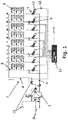
- Fig. 1 is a schematic illustration of a heating flow circuit (1) such as a one-pipe system comprising a connection (2) to a heat supply (3), such as a district heating system.
- a heat transferring fluid is delivered through a supply line (4) to a plural of heating lines (5), or risers, positioned in parallel along the supply line (4) connecting it to a return line (6).
- the heating lines (5) may connect to a plurality of individual heat exchanging circuits each comprising heat exchanging devices (8) (such as radiators etc.), where each of these could form the heating circuit for an individual flat, or just a domestic places in general. These circuits comprising the heat exchanging devices (8) are positioned in series along the heating lines, but by-pass lines ensure the distribution of fluid despite one would be closed.
- the heating lines (5) further includes flow controllers (7) positioned downstream of the heat exchanging devices (8).
- Sensors such as flow sensors and/or temperature sensors (9) may be connected to some or all of the heating lines (5), where the illustrated embodiment shows them positioned downstream of the heat exchanging devices (8) but upstream of the flow controllers (7).
- sensors such as flow sensors and/or temperature sensors (10) may be connected to the supply line (4), return line (6), the connection (2) etc.
- a controller (11) is in data communication (12) connection to actuating means (13) (or just actuator) of the flow controllers (7) to adjust the flow rates in response to the control signal from the controller (11).
- the flow controllers (7) in an embodiment are valves including a valve element operating in connecting to a throttling element (or valve seat) together defining a valve opening given by the position of the valve element relative to the throttling element. The valve opening then defines the flow rate through the valve, and thus the flow system where to it is connected.
- a throttling element or valve seat
- the valve opening then defines the flow rate through the valve, and thus the flow system where to it is connected.
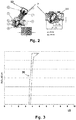
- One such embodiment valve (7) is illustrated in fig. 2 , the illustrated valve being a pressure independent valve including a pressure controlling part (14) formed of a membrane deflecting in response to a pressure difference over the flow controlling means as pressure control.
- Other embodiments of pressure independent valves (7) would also apply, just as non-pressure independent valves (7).
- the flow controllers (7) in an embodiment is thermal controllers changing flow in response to a change in the temperature of the heat exchanging fluid, such as the actuating means (13) could be a wax thermal actuator, but the present inventions could also apply to other types of actuators, such as where there is a significant time delay in the response.
- a return temperature control, RTC, in a flow system (1) such as a one-pipe heating system is a control method where the flow rate in the individual heating lines (5) is adjusted such as to maintain a given set temperature downstream of the last of the heat exchanging devices (8), thus being the return temperature, at a given setpoint, which may be adjusted according to other conditions, such as external temperature etc.
- This method can be used to turn an otherwise traditionally constant flow one-pipe heating system into variable flow system and the one-pipe system can work at partial loads, resulting in increased energy efficiency.
- Fig. 3 illustrate a situation of an embodiment where the actuating means (13) is, or includes, a thermal wax actuator.
- a thermal wax actuator Such wax thermostatic elements transform heat energy into mechanical energy using the thermal expansion of waxes when they melt, but usually only have closed or open positions.
- a transfer curve (30) between closed and open position is illustrated as being quite steep in relation to the control signal (15), thus roughly for all the control signals (15) below the point of reaction the actuator (13) will be closed and for all control signals (15) above the point of reaction it will be fully open.
- This point of reaction corresponds to certain minimum control signal (15) before the actuator (15) (or wax) reacts, and may fluctuate significantly such a in dependence on the ambient temperature. Seen in time it may have a significant delay, at least at low loads as will also be addressed later.
- the X-axis represent the control signal range (15) from 0 (no signal, or 0% signal) to 1 (full signal, or 100% signal), where the curve (30) illustrates the actuating setting in at a control signal (15) roughly around 3.5 (or 35%) (the point of reaction), but the exact value will depend on the nature / definition of the control signal (15), the ambient temperature (e.g. amplitude of the PWM impulses as will be described later), the exact actuator (13) embodiment etc.
- Fig. 4 illustrate embodiments of Pulse Width Modulation (PWM) control of the flow controller(s) (7), optionally through the connected actuating means (13), where the controlling signal (15) changes for periods.
- PWM Pulse Width Modulation
- FIG. 4 illustrates embodiments of Pulse Width Modulation (PWM) control of the flow controller(s) (7), optionally through the connected actuating means (13), where the controlling signal (15) changes for periods.
- PWM Pulse Width Modulation
- control signal (15) in this PWM embodiment is related to the fraction of time, or period, the signal is fully on in relation to the full cycle period, and closed for the rest of the cycle period.
- the full cycle period P may be constant or change over time and may be adjustable, the open period Po and closed period Pc being adjusted accordingly,
- actuating means (13) For flow controllers (7) including or attached to actuating means (13), where the actuating means has some delay in its response, or at least a response time being such that problems may occur at low loads (or low flow rates), or at too high flow temperature (high flow rates), the slow response nature of the actuators (13) can compromise the control performance which may result is oscillation of the controlled return temperature.
- actuating means (13) is thermal wax actuators, where due to nature of heating wax element, it can take up to 3-4 minutes for actuator to start actuating, following by 3-4 minutes of opening time, and the end result can be 8 minutes response. The opposite happens in case of full load.
- the controller (11) when the load gets low, meaning a low flow rate and/or return temperature is below a given threshold, the controller (11) will change the controlling signal (15) by a low load control (22a) (see fig. 5 ) in a manner where it is newer at 0%the whole of the cycle period P. T hereby it is ensured that the response time of the actuating means (13) will be significantly faster. This could be such as by setting the control signal (15) at a level below the point of reaction, such as below 20%, or below 10% or below 5%.
- the closing signal meaning the signal to keep the flow controller (7) closed will be above zero, but sufficiently below a range of point of reactions as they may be expected to fluctuate according to e.g. the expected changes in ambient temperature.
- the low load control (22a) helps to prevent the actuating means (13) to be too cold.
- the controller (11) when the load is high, (or meaning a high flow rate and/or return temperature is above a given threshold) the controller (11) will change the controlling signal (15) by a high load control (22b) (see fig. 5A ) in a manner where it is newer at 100%the whole of the cycle period P. Thereby it is ensured that the response time of the actuating means (13) will be significantly faster. This could be such as by setting the control signal (15) at a level above the point of reaction, such as above 80%, or above 90% or above 95%.
- the closing signal meaning the signal to keep the flow controller (7) open be below zero, but sufficiently above a range of point of reactions as they may be expected to fluctuate according to e.g. the expected changes in ambient temperature.
- the high load control (22b) helps to prevent the actuating means (13) to be overheated.
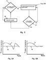
- a basic flow chart is shown illustrates the control method as run by the controller (11) according to an embodiment.
- the system normally will operate in a normal load situation where the system the control signals (15) is run under a normal control method (20) when the load is within a given load threshold, this is when the load is above a low load threshold and/or below a high load threshold.
- the load When the load becomes low (21), meaning if a low flow rate and/or return temperature is below the given low load threshold, it will start the a low load control (22a) where the control signal (15) includes a non-zero opening period Po, where the signal Po is lower than the critical point of reaction , Alternatively, when the load becomes high (21), meaning if a high flow rate and/or return temperature is above the given low load threshold, it will start the a high load control (22b) where the control signal (15) includes an opening period Po ⁇ 100%, where the signal Po is higher than the critical point of reaction
- the method will return to the ordinary control method (20), being how the control is performed during normal load, otherwise it will repeat from the step (22a, 22b).
- the controller (11) regulates according to a PID control.
- Figs. 6A and 6B schematically illustrate the control of the return temperature Tr according to a return temperature setpoint (40) where Fig. 6A schematically illustrates the control according to a PI control method and 6B according to a PID control method.
- the PID control includes three parts, where the part 'P' accounts for present values of the error (where a large and positive error gives a large and positive control output etc.).
- the part 'I' is an integration and accounts for past values of the error, where with an insufficient current output the error will accumulate over time, and the controller will respond by applying a stronger action. This is what is illustrated in fig. 6A , where it has been experienced event when controlling according to the above described low load control (22a) method and/or high load control (22b), the problem of oscillations may still not be fully solved, though still significantly improved, the system may react too quickly.
- the 'D' (the differential part), is included (the full PID control), where this part accounts for possible future values of the error, based on its current rate of change.
Landscapes
- Engineering & Computer Science (AREA)
- Physics & Mathematics (AREA)
- Thermal Sciences (AREA)
- Chemical & Material Sciences (AREA)
- Combustion & Propulsion (AREA)
- Mechanical Engineering (AREA)
- General Engineering & Computer Science (AREA)
- Control Of Temperature (AREA)
- Feedback Control In General (AREA)
Abstract
Description
- The present invention relates to a method to control a flow regulating device, such as for heating systems and such as a valve, when the load becomes low and/or high, and to a controller performing this method.
- When such flow regulating devices are operated by actuating means having a significant delay this may lead to oscillations on the control, which predominantly is a problem when the load (e.g. a controlled flow rate depending on a return temperature of heating fluid) gets close to the limits of the flow regulating device, such as a valve opening getting near its closing position or getting near its full open position.
- The object of the present invention thus is to introduce a method and controller to address these problems.
- The present invention thus introduces a method to control a fluid flow regulating device being regulated through a control signal ranging from 0-100% during a normal operational load, defined as being within a given load threshold, where said control signal is 0% when said flow regulating device is to be closed and 100% when it is to be open, but when said load gets outside said load threshold the control enters a modified control where said control signal either is never at 0% and/or is never at 100%. Thereby possible connected actuating means at all times in this modified control will be stimulated, thus shortening the response time. In an embodiment where the actuating means is a thermal wax actuator this would mean it would never get fully cold or fully heated.
- The control signal may be a pulse width modulated signal (PWM), where said modified control signal is formed of full cycle periods, P, each with open period Po of a 100% control signal and a closed period Pc of 0% signal and when the load gets below a low load threshold said control signal enters a low load control where the open period Po is higher than zero even when the flow regulating device are to be closed and/or when the load gets above a high load threshold said control signal enters a high load control where the open period Po is lower than 100% even when the flow regulating device are to be fully open.
- In an embodiment the fluid flow regulating device is connected to actuating means setting fluid flow regulating device according to the communicated control signal from a connected controller.
- In an embodiment the control signals includes a low load control where the control signal is below a point of reaction defined as the signal where the actuator (13) change flow regulating device between open and closed and/or where the control signal high load control is above said point of reaction. The high load threshold and low load threshold defining when the control are to change to high load or low load control respectively would have to be at an significant distance to the average point of reaction as this is dependent on factors such as the ambient temperature. In one embodiment the high load threshold and/or low load threshold is non-constant, but is depending on factors such as ambient temperature.
- In an embodiment the flow regulating device is pressure independent, and may form part of a valve arrangement including a pressure controlling valve means.
- In an embodiment the fluid flow regulating device adjusts the flow rate to maintain a set reference return temperature in a flow system, said low load related to a low flow rate and/or return temperature Tr being below a given threshold.
- To make the controlling of the fluid regulating device such as to detect when the load gets outside the normal load thresholds (above the high load threshold or below the low load threshold), temperature sensors (9) are connected to the fluid flow system including the fluid flow regulating device and communicates the measurements to the controller as input parameter(s) to the control of the fluid flow regulating device.
- In one embodiment the fluid flow system is a one pipe heating system and where at least one of said temperature sensors is connected to the return side of a heating line.
- In one embodiment for the low load control, the open period Po is equal to or lower than or equal 10%, or 20%, of the total period P, and the closed period Pc is higher than or equal to 90%, or 80%, of the total period P and/or for the high load period open period Po is equal to or higher than or equal 90%, or 80%, of the total period P, and the closed period Pc is lower than or equal to 10%, or 20%, of the total period P
- In an embodiment the control is even more improved the control of the return temperature, Tr, include a PID control.
- The present invention further relate to a controller adapted to regulate a fluid flow regulating device by a control signal being 0% when said fluid flow regulating device is to be closed and 100% when it is to be fully open during a normal operational load, defined as being within a load threshold, and where the controller is in data communication with means to detect said load, characterized in that said controller includes a modified control signal where said control signal either is never at 0% and/or is never at 100%, and enters said modified control signal when the load is outside said load threshold.
- In various embodiments, the controller is adapted to operate according to the method of any of previous embodiments.
-
- Fig. 1
- A one-pipe hating flow circuit including a connection to a heat supply, such as a district heating system, and heat exchanging devices, such as radiators.
- Fig. 2
- A pressure independent flow controller.
- Fig. 3
- Illustration of the actuation of a wax actuator according to a controlling signal.
- Fig. 4
- Illustrate controlling signals formed as pulse width modulated signals (PWM).
- Fig. 5
- Flow chart illustrating the method of introducing a modified control signal when the load is outside a given threshold.
- Fig. 6A,B
- Illustrations of a system using respectively a PI and PID control method of a return temperature.
-
Fig. 1 is a schematic illustration of a heating flow circuit (1) such as a one-pipe system comprising a connection (2) to a heat supply (3), such as a district heating system. A heat transferring fluid is delivered through a supply line (4) to a plural of heating lines (5), or risers, positioned in parallel along the supply line (4) connecting it to a return line (6). - The heating lines (5) may connect to a plurality of individual heat exchanging circuits each comprising heat exchanging devices (8) (such as radiators etc.), where each of these could form the heating circuit for an individual flat, or just a domestic places in general. These circuits comprising the heat exchanging devices (8) are positioned in series along the heating lines, but by-pass lines ensure the distribution of fluid despite one would be closed. The heating lines (5) further includes flow controllers (7) positioned downstream of the heat exchanging devices (8).
- Sensors, such as flow sensors and/or temperature sensors (9) may be connected to some or all of the heating lines (5), where the illustrated embodiment shows them positioned downstream of the heat exchanging devices (8) but upstream of the flow controllers (7).
- Further, sensors, such as flow sensors and/or temperature sensors (10) may be connected to the supply line (4), return line (6), the connection (2) etc.
- A controller (11) is in data communication (12) connection to actuating means (13) (or just actuator) of the flow controllers (7) to adjust the flow rates in response to the control signal from the controller (11).
- The flow controllers (7) in an embodiment are valves including a valve element operating in connecting to a throttling element (or valve seat) together defining a valve opening given by the position of the valve element relative to the throttling element. The valve opening then defines the flow rate through the valve, and thus the flow system where to it is connected. One such embodiment valve (7) is illustrated in
fig. 2 , the illustrated valve being a pressure independent valve including a pressure controlling part (14) formed of a membrane deflecting in response to a pressure difference over the flow controlling means as pressure control. Other embodiments of pressure independent valves (7) would also apply, just as non-pressure independent valves (7). - The flow controllers (7) in an embodiment is thermal controllers changing flow in response to a change in the temperature of the heat exchanging fluid, such as the actuating means (13) could be a wax thermal actuator, but the present inventions could also apply to other types of actuators, such as where there is a significant time delay in the response.
- A return temperature control, RTC, in a flow system (1) such as a one-pipe heating system is a control method where the flow rate in the individual heating lines (5) is adjusted such as to maintain a given set temperature downstream of the last of the heat exchanging devices (8), thus being the return temperature, at a given setpoint, which may be adjusted according to other conditions, such as external temperature etc. This method can be used to turn an otherwise traditionally constant flow one-pipe heating system into variable flow system and the one-pipe system can work at partial loads, resulting in increased energy efficiency.
-
Fig. 3 illustrate a situation of an embodiment where the actuating means (13) is, or includes, a thermal wax actuator. Such wax thermostatic elements transform heat energy into mechanical energy using the thermal expansion of waxes when they melt, but usually only have closed or open positions. Infig. 3 a transfer curve (30) between closed and open position is illustrated as being quite steep in relation to the control signal (15), thus roughly for all the control signals (15) below the point of reaction the actuator (13) will be closed and for all control signals (15) above the point of reaction it will be fully open. This point of reaction corresponds to certain minimum control signal (15) before the actuator (15) (or wax) reacts, and may fluctuate significantly such a in dependence on the ambient temperature. Seen in time it may have a significant delay, at least at low loads as will also be addressed later. - In the illustration
fig. 3 the X-axis represent the control signal range (15) from 0 (no signal, or 0% signal) to 1 (full signal, or 100% signal), where the curve (30) illustrates the actuating setting in at a control signal (15) roughly around 3.5 (or 35%) (the point of reaction), but the exact value will depend on the nature / definition of the control signal (15), the ambient temperature (e.g. amplitude of the PWM impulses as will be described later), the exact actuator (13) embodiment etc. - It should in general be noted that
fig. 3 , just as the other figures, are just to illustrate the concept of embodiments of the present invention, the exact details, values, graphs etc. just being disclosed as example. -
Fig. 4 illustrate embodiments of Pulse Width Modulation (PWM) control of the flow controller(s) (7), optionally through the connected actuating means (13), where the controlling signal (15) changes for periods. In the figure four different control signals (15) are illustrated, each ranging over a cycle period P being the sum of the period Po where the control signal (15) is on (in the illustrated embodiment meaning it is at full signal equal to 100%) and the period Pc where it is closed (in the illustrated embodiment meaning it is at no signal equal to 0%). In the actual systems the control signal (15) usually will be a voltage or current at some magnitude (amplitude of the pulses), but in thefigures 3 and4 this is normalized to a range from 0-100%, or as showing infig. 3 , a fraction from 0-1. - The four different control signals (15) schematically illustrated includes a 50% control signal (15a) being that the control signal (15) is on for 50% of the time of the cycle period P, thus Po = Pc = 50%, or 0.5 in the alternative scale. The second control signal (15b) illustrated is on for 30% of the time of the cycle period P, thus Po = 30% and Pc = 70% of the cycle period P. The third control signal (15c) illustrated is on for 10% of the time of the cycle period P, thus Po = 10% and Pc = 90% of the cycle period P. The fourth control signal (15d) illustrated is on for 90% of the time of the cycle period P, thus Po = 90% and Pc = 10% of the cycle period P. Full signal thus would be the control signal (15) is on the full cycle period P, and no signal would be the control signal (15) off the full cycle period P. In more general terms, the control signal (15) in this PWM embodiment is related to the fraction of time, or period, the signal is fully on in relation to the full cycle period, and closed for the rest of the cycle period. The full cycle period P may be constant or change over time and may be adjustable, the open period Po and closed period Pc being adjusted accordingly,
- In the situation with a of low load on the flow system (1), where only a small amount of heat is extracted by the heat exchanging devices (8), the control performance becomes increasingly important.
- For flow controllers (7) including or attached to actuating means (13), where the actuating means has some delay in its response, or at least a response time being such that problems may occur at low loads (or low flow rates), or at too high flow temperature (high flow rates), the slow response nature of the actuators (13) can compromise the control performance which may result is oscillation of the controlled return temperature. One example of such actuating means (13) is thermal wax actuators, where due to nature of heating wax element, it can take up to 3-4 minutes for actuator to start actuating, following by 3-4 minutes of opening time, and the end result can be 8 minutes response. The opposite happens in case of full load.
- In an embodiment, when the load gets low, meaning a low flow rate and/or return temperature is below a given threshold, the controller (11) will change the controlling signal (15) by a low load control (22a) (see
fig. 5 ) in a manner where it is newer at 0%the whole of the cycle period P. T hereby it is ensured that the response time of the actuating means (13) will be significantly faster. This could be such as by setting the control signal (15) at a level below the point of reaction, such as below 20%, or below 10% or below 5%. - Thus, at low load the closing signal, meaning the signal to keep the flow controller (7) closed will be above zero, but sufficiently below a range of point of reactions as they may be expected to fluctuate according to e.g. the expected changes in ambient temperature. The low load control (22a) helps to prevent the actuating means (13) to be too cold.
- In an embodiment, if the flow rate and/or return temperature is outside the given threshold scope the method will return to the ordinary control method.
- In an embodiment, as an additional or alternative feature, when the load is high, (or meaning a high flow rate and/or return temperature is above a given threshold) the controller (11) will change the controlling signal (15) by a high load control (22b) (see
fig. 5A ) in a manner where it is newer at 100%the whole of the cycle period P. Thereby it is ensured that the response time of the actuating means (13) will be significantly faster. This could be such as by setting the control signal (15) at a level above the point of reaction, such as above 80%, or above 90% or above 95%. - Thus, at high load the closing signal, meaning the signal to keep the flow controller (7) open be below zero, but sufficiently above a range of point of reactions as they may be expected to fluctuate according to e.g. the expected changes in ambient temperature. The high load control (22b) helps to prevent the actuating means (13) to be overheated.
- In
fig. 5 a basic flow chart is shown illustrates the control method as run by the controller (11) according to an embodiment. The system normally will operate in a normal load situation where the system the control signals (15) is run under a normal control method (20) when the load is within a given load threshold, this is when the load is above a low load threshold and/or below a high load threshold. - When the load becomes low (21), meaning if a low flow rate and/or return temperature is below the given low load threshold, it will start the a low load control (22a) where the control signal (15) includes a non-zero opening period Po, where the signal Po is lower than the critical point of reaction , Alternatively, when the load becomes high (21), meaning if a high flow rate and/or return temperature is above the given low load threshold, it will start the a high load control (22b) where the control signal (15) includes an opening period Po < 100%, where the signal Po is higher than the critical point of reaction
- In an embodiment, if the flow rate and/or return temperature is outside the given threshold scope (23) the method will return to the ordinary control method (20), being how the control is performed during normal load, otherwise it will repeat from the step (22a, 22b).
- In an embodiment the controller (11) regulates according to a PID control.
Figs. 6A and 6B schematically illustrate the control of the return temperature Tr according to a return temperature setpoint (40) whereFig. 6A schematically illustrates the control according to a PI control method and 6B according to a PID control method. - The PID control includes three parts, where the part 'P' accounts for present values of the error (where a large and positive error gives a large and positive control output etc.). The part 'I' is an integration and accounts for past values of the error, where with an insufficient current output the error will accumulate over time, and the controller will respond by applying a stronger action. This is what is illustrated in
fig. 6A , where it has been experienced event when controlling according to the above described low load control (22a) method and/or high load control (22b), the problem of oscillations may still not be fully solved, though still significantly improved, the system may react too quickly. - Therefore in an embodiment the 'D' (the differential part), is included (the full PID control), where this part accounts for possible future values of the error, based on its current rate of change.
Claims (15)
- A method to control a fluid flow regulating device (7) being regulated through a control signal (15) ranging from 0-100% during a normal operational load, defined as being within a given load threshold, where said control signal (15) is 0% when said fluid flow regulating device (7) is to be closed and 100% when it is to be open, characterized in that when said load gets outside said load threshold the control enters a modified control (22a, 22b) where said control signal (15) either is never at 0% and/or is never at 100%.
- A method to control a fluid flow regulating device (7) according to claim 1, wherein said modified control signal (22) is formed of full cycle periods, P, each with open period Po of a 100% control signal (15) and a closed period Pc of 0% signal and when the load gets below a low load threshold said control signal (15) enters a low load control (22a) where the open period Po is higher than zero even when the flow regulating device (7) are to be closed and/or when the load gets above a high load threshold said control signal (15) enters a high load control (22b) where the open period Po is lower than 100% even when the flow regulating device (7) are to be fully open.
- The method according to claim 2, wherein the fluid flow regulating device (7) is connected to actuating means (13) setting fluid flow regulating device (7) according to the communicated control signal (15) from a connected controller (11).
- The method according to claim 3, where the control signals (15) in the low load control (22a) is below a point of reaction defined as the control signal (15) where the actuator (13) change flow regulating device (7) between open and closed and/or where the control signal (15) high load control (22b) is above said point of reaction.
- The method according to claim 4, wherein the high load threshold and/or low load threshold depending on the ambient temperature.
- The method according to claim 5, wherein in the low load control (22a) the open period Po is equal to or lower than 10% of the total period P, and the closed period Pc is higher than or equal to 90% of the total period P, and/or in the high load control (22b) the open period Po is equal to or higher than 90% of the total period P, and the closed period Pc is lower than or equal to 10% of the total period P
- The method according to claim 6, wherein in the low load control (22a) the open period Po is equal to or lower than 20% of the total period P, and the closed period Pc is higher than or equal to 80% of the total period P, and/or in the high load control (22b) the open period Po is equal to or higher than 80% of the total period P, and the closed period Pc is lower than or equal to 20% of the total period P
- The method according to any of the previous claims, wherein the method includes the control of a return temperature Tr by a PID control.
- A controller (11) adapted to regulate a fluid flow regulating device (7)by a control signal (15) being 0% when said fluid flow regulating device (7) is to be closed and 100% when it is to be fully open during a normal operational load, defined as being within a load threshold, and where the controller (11) is in data communication with means to detect said load, characterized in that said controller (11) includes a modified control signal (22) where said control signal (15) either is never at 0% and/or is never at 100%, and enters said modified control signal when the load is outside said load threshold.
- The controller (11) according to claim 9, wherein the fluid flow regulating device (7) forms part of a valve arrangement including a pressure controlling valve means (14).
- The controller (11) according to claim 10, wherein the fluid flow regulating device (7) adjusts the flow rate to maintain a set reference return temperature (40) in a flow system (1), said low load related to a low flow rate and/or return temperature, Tr, being below a given threshold.
- The controller (11) according to claim 11, wherein temperature sensors (9) connected to the fluid flow system (1) including the fluid flow regulating device (7) and communicates the measurements to the controller (11) as input parameter(s) to the control of the fluid flow regulating device (7).
- The controller (11) according to claim 12, wherein the fluid flow system (1) is a one pipe heating system and where at least one of said temperature sensors (9) is connected to the return side of a heating line (5).
- A controller (11) according to claim 13 adapted to operate according to the method of any of the claims 2-7.
- A controller (11) according to claim 14 and claim 4, wherein the actuating means (13) is a thermal wax actuator.
Applications Claiming Priority (1)
| Application Number | Priority Date | Filing Date | Title |
|---|---|---|---|
| DKPA201600391A DK179749B1 (en) | 2016-06-30 | 2016-06-30 | Control of flow regulating device |
Publications (2)
| Publication Number | Publication Date |
|---|---|
| EP3263996A1 true EP3263996A1 (en) | 2018-01-03 |
| EP3263996B1 EP3263996B1 (en) | 2023-04-19 |
Family
ID=59093390
Family Applications (1)
| Application Number | Title | Priority Date | Filing Date |
|---|---|---|---|
| EP17175930.1A Active EP3263996B1 (en) | 2016-06-30 | 2017-06-14 | Control of flow regulating device |
Country Status (6)
| Country | Link |
|---|---|
| EP (1) | EP3263996B1 (en) |
| CN (1) | CN107559941B (en) |
| DK (1) | DK179749B1 (en) |
| LT (1) | LT3263996T (en) |
| PL (1) | PL3263996T3 (en) |
| RU (1) | RU2667851C1 (en) |
Cited By (2)
| Publication number | Priority date | Publication date | Assignee | Title |
|---|---|---|---|---|
| BE1027799B1 (en) * | 2019-11-27 | 2021-06-23 | Bess Energie Sprl | Sliding temperature regulation of the water in the heating / chilled water return circuits with a view to their automatic standardization and, ultimately, by way of optimizing yields |
| US11187345B2 (en) | 2019-02-27 | 2021-11-30 | Hamilton Sundstrand Corporation | Paraffin actuated diaphragm valve |
Citations (6)
| Publication number | Priority date | Publication date | Assignee | Title |
|---|---|---|---|---|
| US6152376A (en) * | 1997-02-21 | 2000-11-28 | Heat-Timer Corporation | Valve modulation method and system utilizing same |
| DE10302176A1 (en) * | 2003-01-22 | 2004-07-29 | Mvv Energie Ag | Temperature regulation device for an instantaneous hot drinking water heater, whereby water temperature is set using a regulator that forms part of a closed control loop with input water temperature sensor measurements |
| DE102009004319A1 (en) * | 2009-01-10 | 2010-07-22 | Henry Klein | Method for performing hydraulic balance of heat exchanger of circulatory composite system in building, involves detecting return temperature at heat exchanger and controlling volumetric flow rate by heat exchanger as function of temperature |
| EP2395289A2 (en) * | 2010-06-10 | 2011-12-14 | Danfoss A/S | Method to regulate a one-pipe heat supply system |
| EP2423607A2 (en) * | 2010-06-10 | 2012-02-29 | Danfoss A/S | One-pipe heat supply system with flow regulation |
| EP3009909A1 (en) * | 2014-10-16 | 2016-04-20 | Danfoss A/S | Actuator means and heating system |
Family Cites Families (10)
| Publication number | Priority date | Publication date | Assignee | Title |
|---|---|---|---|---|
| RU2217665C2 (en) * | 1998-12-04 | 2003-11-27 | Байтингер Николай Михайлович | Liquid flow rate regulator |
| DE10005856B4 (en) * | 1999-06-25 | 2004-02-26 | Viessmann Werke Gmbh & Co Kg | Method and device for controlling a variable in a heating system |
| DE10054897B4 (en) * | 2000-11-06 | 2005-01-13 | Techem Service Ag & Co. Kg | Regulation for floor heating or combined floor and radiator heating |
| JP2004197663A (en) * | 2002-12-19 | 2004-07-15 | Tgk Co Ltd | Control device for displacement control valve |
| WO2012032813A1 (en) * | 2010-09-06 | 2012-03-15 | アイシン精機株式会社 | Oil pressure control device |
| CH706146A2 (en) * | 2012-02-29 | 2013-08-30 | Oblamatik Ag | Method and system for tempering components. |
| EP2871539B1 (en) * | 2013-11-07 | 2019-04-17 | Grundfos Holding A/S | Diagnosis method for diagnosing the proper operation of a heating system and/or cooling system |
| AT515085B1 (en) * | 2014-01-16 | 2015-06-15 | Vaillant Group Austria Gmbh | Method for adaptive control of a heating system |
| EP3009751B1 (en) * | 2014-10-16 | 2019-01-16 | Danfoss A/S | Heating system and method for hydraulic balancing said heating system |
| CN104533865B (en) * | 2015-01-08 | 2017-04-05 | 中国人民解放军国防科学技术大学 | A kind of hydraulic energy-saving controller |
-
2016
- 2016-06-30 DK DKPA201600391A patent/DK179749B1/en active IP Right Grant
-
2017
- 2017-06-14 EP EP17175930.1A patent/EP3263996B1/en active Active
- 2017-06-14 LT LTEP17175930.1T patent/LT3263996T/en unknown
- 2017-06-14 PL PL17175930.1T patent/PL3263996T3/en unknown
- 2017-06-26 RU RU2017122339A patent/RU2667851C1/en active
- 2017-06-29 CN CN201710518869.9A patent/CN107559941B/en active Active
Patent Citations (6)
| Publication number | Priority date | Publication date | Assignee | Title |
|---|---|---|---|---|
| US6152376A (en) * | 1997-02-21 | 2000-11-28 | Heat-Timer Corporation | Valve modulation method and system utilizing same |
| DE10302176A1 (en) * | 2003-01-22 | 2004-07-29 | Mvv Energie Ag | Temperature regulation device for an instantaneous hot drinking water heater, whereby water temperature is set using a regulator that forms part of a closed control loop with input water temperature sensor measurements |
| DE102009004319A1 (en) * | 2009-01-10 | 2010-07-22 | Henry Klein | Method for performing hydraulic balance of heat exchanger of circulatory composite system in building, involves detecting return temperature at heat exchanger and controlling volumetric flow rate by heat exchanger as function of temperature |
| EP2395289A2 (en) * | 2010-06-10 | 2011-12-14 | Danfoss A/S | Method to regulate a one-pipe heat supply system |
| EP2423607A2 (en) * | 2010-06-10 | 2012-02-29 | Danfoss A/S | One-pipe heat supply system with flow regulation |
| EP3009909A1 (en) * | 2014-10-16 | 2016-04-20 | Danfoss A/S | Actuator means and heating system |
Cited By (2)
| Publication number | Priority date | Publication date | Assignee | Title |
|---|---|---|---|---|
| US11187345B2 (en) | 2019-02-27 | 2021-11-30 | Hamilton Sundstrand Corporation | Paraffin actuated diaphragm valve |
| BE1027799B1 (en) * | 2019-11-27 | 2021-06-23 | Bess Energie Sprl | Sliding temperature regulation of the water in the heating / chilled water return circuits with a view to their automatic standardization and, ultimately, by way of optimizing yields |
Also Published As
| Publication number | Publication date |
|---|---|
| DK201600391A1 (en) | 2018-01-08 |
| DK179749B1 (en) | 2019-05-07 |
| RU2667851C1 (en) | 2018-09-24 |
| CN107559941B (en) | 2019-12-13 |
| LT3263996T (en) | 2023-05-10 |
| EP3263996B1 (en) | 2023-04-19 |
| CN107559941A (en) | 2018-01-09 |
| PL3263996T3 (en) | 2023-09-11 |
Similar Documents
| Publication | Publication Date | Title |
|---|---|---|
| US9631831B2 (en) | Method for controlling the opening of an HVAC valve based on the energy-per-flow gradient | |
| CA3076442C (en) | Self-regulating adjustment device for a flow control valve, a temperature control system and a distributor device having the same, and associated methods | |
| AU2005230524B2 (en) | Cooling and/or heating device | |
| CN101118054B (en) | Steam temperature control in a boiler using a pid controller. | |
| US7850572B2 (en) | Hydraulic over/undershoot protection for transmission clutch control | |
| EP3263996B1 (en) | Control of flow regulating device | |
| EP2187136A2 (en) | Method for operating a system for transporting thermal energy through a liquid medium | |
| EP2423607A2 (en) | One-pipe heat supply system with flow regulation | |
| EP3093729B1 (en) | Valve actuator with setting actuator | |
| CN112912812A (en) | Method for operating a valve, associated electronic control unit and valve drive | |
| US11609019B2 (en) | Device and method for controlling an orifice of a valve in an HVAC system | |
| EP3407153A1 (en) | Control of pressure controller at border values | |
| WO2003023288A1 (en) | Central heating installation | |
| DE10154198A1 (en) | Device and method for regulating thermal baths | |
| EP3506043B1 (en) | Method for controlling a heating or cooling system | |
| CN118076836A (en) | Heating system with automatic pressure differential setting | |
| NL192541C (en) | Method for setting the average value of the supply temperature of a heating liquid, which is heated intermittently in a heating system, and a control device for this. | |
| CN114207547B (en) | Adjusting device and method for improved fine adjustment of valve play | |
| CN114207548B (en) | Adjusting device and method for determining a hydraulic threshold of a valve | |
| Shinskey et al. | 2.6 Control Systems—Cascade Loops | |
| EP3798520B1 (en) | Electronically controlled by-pass | |
| RU2778404C1 (en) | Heat exchange system | |
| EP3009909B1 (en) | Actuator means and heating system | |
| EP3495912A1 (en) | Parallel valve control | |
| CN119156506A (en) | Method for monitoring and/or controlling a heating installation |
Legal Events
| Date | Code | Title | Description |
|---|---|---|---|
| PUAI | Public reference made under article 153(3) epc to a published international application that has entered the european phase |
Free format text: ORIGINAL CODE: 0009012 |
|
| STAA | Information on the status of an ep patent application or granted ep patent |
Free format text: STATUS: THE APPLICATION HAS BEEN PUBLISHED |
|
| AK | Designated contracting states |
Kind code of ref document: A1 Designated state(s): AL AT BE BG CH CY CZ DE DK EE ES FI FR GB GR HR HU IE IS IT LI LT LU LV MC MK MT NL NO PL PT RO RS SE SI SK SM TR |
|
| AX | Request for extension of the european patent |
Extension state: BA ME |
|
| STAA | Information on the status of an ep patent application or granted ep patent |
Free format text: STATUS: REQUEST FOR EXAMINATION WAS MADE |
|
| 17P | Request for examination filed |
Effective date: 20180620 |
|
| RBV | Designated contracting states (corrected) |
Designated state(s): AL AT BE BG CH CY CZ DE DK EE ES FI FR GB GR HR HU IE IS IT LI LT LU LV MC MK MT NL NO PL PT RO RS SE SI SK SM TR |
|
| STAA | Information on the status of an ep patent application or granted ep patent |
Free format text: STATUS: EXAMINATION IS IN PROGRESS |
|
| 17Q | First examination report despatched |
Effective date: 20200508 |
|
| GRAP | Despatch of communication of intention to grant a patent |
Free format text: ORIGINAL CODE: EPIDOSNIGR1 |
|
| STAA | Information on the status of an ep patent application or granted ep patent |
Free format text: STATUS: GRANT OF PATENT IS INTENDED |
|
| INTG | Intention to grant announced |
Effective date: 20221216 |
|
| GRAS | Grant fee paid |
Free format text: ORIGINAL CODE: EPIDOSNIGR3 |
|
| GRAA | (expected) grant |
Free format text: ORIGINAL CODE: 0009210 |
|
| STAA | Information on the status of an ep patent application or granted ep patent |
Free format text: STATUS: THE PATENT HAS BEEN GRANTED |
|
| AK | Designated contracting states |
Kind code of ref document: B1 Designated state(s): AL AT BE BG CH CY CZ DE DK EE ES FI FR GB GR HR HU IE IS IT LI LT LU LV MC MK MT NL NO PL PT RO RS SE SI SK SM TR |
|
| REG | Reference to a national code |
Ref country code: GB Ref legal event code: FG4D |
|
| REG | Reference to a national code |
Ref country code: CH Ref legal event code: EP |
|
| REG | Reference to a national code |
Ref country code: DE Ref legal event code: R096 Ref document number: 602017067786 Country of ref document: DE |
|
| REG | Reference to a national code |
Ref country code: IE Ref legal event code: FG4D |
|
| REG | Reference to a national code |
Ref country code: AT Ref legal event code: REF Ref document number: 1561452 Country of ref document: AT Kind code of ref document: T Effective date: 20230515 |
|
| P01 | Opt-out of the competence of the unified patent court (upc) registered |
Effective date: 20230617 |
|
| REG | Reference to a national code |
Ref country code: NL Ref legal event code: MP Effective date: 20230419 |
|
| REG | Reference to a national code |
Ref country code: AT Ref legal event code: MK05 Ref document number: 1561452 Country of ref document: AT Kind code of ref document: T Effective date: 20230419 |
|
| PG25 | Lapsed in a contracting state [announced via postgrant information from national office to epo] |
Ref country code: NL Free format text: LAPSE BECAUSE OF FAILURE TO SUBMIT A TRANSLATION OF THE DESCRIPTION OR TO PAY THE FEE WITHIN THE PRESCRIBED TIME-LIMIT Effective date: 20230419 |
|
| PG25 | Lapsed in a contracting state [announced via postgrant information from national office to epo] |
Ref country code: SE Free format text: LAPSE BECAUSE OF FAILURE TO SUBMIT A TRANSLATION OF THE DESCRIPTION OR TO PAY THE FEE WITHIN THE PRESCRIBED TIME-LIMIT Effective date: 20230419 Ref country code: PT Free format text: LAPSE BECAUSE OF FAILURE TO SUBMIT A TRANSLATION OF THE DESCRIPTION OR TO PAY THE FEE WITHIN THE PRESCRIBED TIME-LIMIT Effective date: 20230821 Ref country code: NO Free format text: LAPSE BECAUSE OF FAILURE TO SUBMIT A TRANSLATION OF THE DESCRIPTION OR TO PAY THE FEE WITHIN THE PRESCRIBED TIME-LIMIT Effective date: 20230719 Ref country code: ES Free format text: LAPSE BECAUSE OF FAILURE TO SUBMIT A TRANSLATION OF THE DESCRIPTION OR TO PAY THE FEE WITHIN THE PRESCRIBED TIME-LIMIT Effective date: 20230419 Ref country code: AT Free format text: LAPSE BECAUSE OF FAILURE TO SUBMIT A TRANSLATION OF THE DESCRIPTION OR TO PAY THE FEE WITHIN THE PRESCRIBED TIME-LIMIT Effective date: 20230419 |
|
| PG25 | Lapsed in a contracting state [announced via postgrant information from national office to epo] |
Ref country code: RS Free format text: LAPSE BECAUSE OF FAILURE TO SUBMIT A TRANSLATION OF THE DESCRIPTION OR TO PAY THE FEE WITHIN THE PRESCRIBED TIME-LIMIT Effective date: 20230419 Ref country code: LV Free format text: LAPSE BECAUSE OF FAILURE TO SUBMIT A TRANSLATION OF THE DESCRIPTION OR TO PAY THE FEE WITHIN THE PRESCRIBED TIME-LIMIT Effective date: 20230419 Ref country code: IS Free format text: LAPSE BECAUSE OF FAILURE TO SUBMIT A TRANSLATION OF THE DESCRIPTION OR TO PAY THE FEE WITHIN THE PRESCRIBED TIME-LIMIT Effective date: 20230819 Ref country code: HR Free format text: LAPSE BECAUSE OF FAILURE TO SUBMIT A TRANSLATION OF THE DESCRIPTION OR TO PAY THE FEE WITHIN THE PRESCRIBED TIME-LIMIT Effective date: 20230419 Ref country code: GR Free format text: LAPSE BECAUSE OF FAILURE TO SUBMIT A TRANSLATION OF THE DESCRIPTION OR TO PAY THE FEE WITHIN THE PRESCRIBED TIME-LIMIT Effective date: 20230720 Ref country code: AL Free format text: LAPSE BECAUSE OF FAILURE TO SUBMIT A TRANSLATION OF THE DESCRIPTION OR TO PAY THE FEE WITHIN THE PRESCRIBED TIME-LIMIT Effective date: 20230419 |
|
| PG25 | Lapsed in a contracting state [announced via postgrant information from national office to epo] |
Ref country code: FI Free format text: LAPSE BECAUSE OF FAILURE TO SUBMIT A TRANSLATION OF THE DESCRIPTION OR TO PAY THE FEE WITHIN THE PRESCRIBED TIME-LIMIT Effective date: 20230419 |
|
| PG25 | Lapsed in a contracting state [announced via postgrant information from national office to epo] |
Ref country code: SK Free format text: LAPSE BECAUSE OF FAILURE TO SUBMIT A TRANSLATION OF THE DESCRIPTION OR TO PAY THE FEE WITHIN THE PRESCRIBED TIME-LIMIT Effective date: 20230419 |
|
| PG25 | Lapsed in a contracting state [announced via postgrant information from national office to epo] |
Ref country code: MC Free format text: LAPSE BECAUSE OF FAILURE TO SUBMIT A TRANSLATION OF THE DESCRIPTION OR TO PAY THE FEE WITHIN THE PRESCRIBED TIME-LIMIT Effective date: 20230419 |
|
| REG | Reference to a national code |
Ref country code: DE Ref legal event code: R097 Ref document number: 602017067786 Country of ref document: DE |
|
| PG25 | Lapsed in a contracting state [announced via postgrant information from national office to epo] |
Ref country code: SM Free format text: LAPSE BECAUSE OF FAILURE TO SUBMIT A TRANSLATION OF THE DESCRIPTION OR TO PAY THE FEE WITHIN THE PRESCRIBED TIME-LIMIT Effective date: 20230419 Ref country code: SK Free format text: LAPSE BECAUSE OF FAILURE TO SUBMIT A TRANSLATION OF THE DESCRIPTION OR TO PAY THE FEE WITHIN THE PRESCRIBED TIME-LIMIT Effective date: 20230419 Ref country code: RO Free format text: LAPSE BECAUSE OF FAILURE TO SUBMIT A TRANSLATION OF THE DESCRIPTION OR TO PAY THE FEE WITHIN THE PRESCRIBED TIME-LIMIT Effective date: 20230419 Ref country code: MC Free format text: LAPSE BECAUSE OF FAILURE TO SUBMIT A TRANSLATION OF THE DESCRIPTION OR TO PAY THE FEE WITHIN THE PRESCRIBED TIME-LIMIT Effective date: 20230419 Ref country code: EE Free format text: LAPSE BECAUSE OF FAILURE TO SUBMIT A TRANSLATION OF THE DESCRIPTION OR TO PAY THE FEE WITHIN THE PRESCRIBED TIME-LIMIT Effective date: 20230419 Ref country code: DK Free format text: LAPSE BECAUSE OF FAILURE TO SUBMIT A TRANSLATION OF THE DESCRIPTION OR TO PAY THE FEE WITHIN THE PRESCRIBED TIME-LIMIT Effective date: 20230419 Ref country code: CZ Free format text: LAPSE BECAUSE OF FAILURE TO SUBMIT A TRANSLATION OF THE DESCRIPTION OR TO PAY THE FEE WITHIN THE PRESCRIBED TIME-LIMIT Effective date: 20230419 |
|
| REG | Reference to a national code |
Ref country code: CH Ref legal event code: PL |
|
| PLBE | No opposition filed within time limit |
Free format text: ORIGINAL CODE: 0009261 |
|
| STAA | Information on the status of an ep patent application or granted ep patent |
Free format text: STATUS: NO OPPOSITION FILED WITHIN TIME LIMIT |
|
| REG | Reference to a national code |
Ref country code: BE Ref legal event code: MM Effective date: 20230630 |
|
| PG25 | Lapsed in a contracting state [announced via postgrant information from national office to epo] |
Ref country code: LU Free format text: LAPSE BECAUSE OF NON-PAYMENT OF DUE FEES Effective date: 20230614 |
|
| 26N | No opposition filed |
Effective date: 20240122 |
|
| GBPC | Gb: european patent ceased through non-payment of renewal fee |
Effective date: 20230719 |
|
| REG | Reference to a national code |
Ref country code: IE Ref legal event code: MM4A |
|
| PG25 | Lapsed in a contracting state [announced via postgrant information from national office to epo] |
Ref country code: LU Free format text: LAPSE BECAUSE OF NON-PAYMENT OF DUE FEES Effective date: 20230614 |
|
| PG25 | Lapsed in a contracting state [announced via postgrant information from national office to epo] |
Ref country code: IE Free format text: LAPSE BECAUSE OF NON-PAYMENT OF DUE FEES Effective date: 20230614 |
|
| PG25 | Lapsed in a contracting state [announced via postgrant information from national office to epo] |
Ref country code: IE Free format text: LAPSE BECAUSE OF NON-PAYMENT OF DUE FEES Effective date: 20230614 Ref country code: GB Free format text: LAPSE BECAUSE OF NON-PAYMENT OF DUE FEES Effective date: 20230719 Ref country code: CH Free format text: LAPSE BECAUSE OF NON-PAYMENT OF DUE FEES Effective date: 20230630 |
|
| PG25 | Lapsed in a contracting state [announced via postgrant information from national office to epo] |
Ref country code: SI Free format text: LAPSE BECAUSE OF FAILURE TO SUBMIT A TRANSLATION OF THE DESCRIPTION OR TO PAY THE FEE WITHIN THE PRESCRIBED TIME-LIMIT Effective date: 20230419 |
|
| PG25 | Lapsed in a contracting state [announced via postgrant information from national office to epo] |
Ref country code: SI Free format text: LAPSE BECAUSE OF FAILURE TO SUBMIT A TRANSLATION OF THE DESCRIPTION OR TO PAY THE FEE WITHIN THE PRESCRIBED TIME-LIMIT Effective date: 20230419 Ref country code: IT Free format text: LAPSE BECAUSE OF FAILURE TO SUBMIT A TRANSLATION OF THE DESCRIPTION OR TO PAY THE FEE WITHIN THE PRESCRIBED TIME-LIMIT Effective date: 20230419 Ref country code: FR Free format text: LAPSE BECAUSE OF NON-PAYMENT OF DUE FEES Effective date: 20230619 Ref country code: BE Free format text: LAPSE BECAUSE OF NON-PAYMENT OF DUE FEES Effective date: 20230630 |
|
| PG25 | Lapsed in a contracting state [announced via postgrant information from national office to epo] |
Ref country code: BG Free format text: LAPSE BECAUSE OF FAILURE TO SUBMIT A TRANSLATION OF THE DESCRIPTION OR TO PAY THE FEE WITHIN THE PRESCRIBED TIME-LIMIT Effective date: 20230419 |
|
| PG25 | Lapsed in a contracting state [announced via postgrant information from national office to epo] |
Ref country code: BG Free format text: LAPSE BECAUSE OF FAILURE TO SUBMIT A TRANSLATION OF THE DESCRIPTION OR TO PAY THE FEE WITHIN THE PRESCRIBED TIME-LIMIT Effective date: 20230419 |
|
| PG25 | Lapsed in a contracting state [announced via postgrant information from national office to epo] |
Ref country code: CY Free format text: LAPSE BECAUSE OF FAILURE TO SUBMIT A TRANSLATION OF THE DESCRIPTION OR TO PAY THE FEE WITHIN THE PRESCRIBED TIME-LIMIT; INVALID AB INITIO Effective date: 20170614 |
|
| PG25 | Lapsed in a contracting state [announced via postgrant information from national office to epo] |
Ref country code: HU Free format text: LAPSE BECAUSE OF FAILURE TO SUBMIT A TRANSLATION OF THE DESCRIPTION OR TO PAY THE FEE WITHIN THE PRESCRIBED TIME-LIMIT; INVALID AB INITIO Effective date: 20170614 |
|
| PG25 | Lapsed in a contracting state [announced via postgrant information from national office to epo] |
Ref country code: TR Free format text: LAPSE BECAUSE OF FAILURE TO SUBMIT A TRANSLATION OF THE DESCRIPTION OR TO PAY THE FEE WITHIN THE PRESCRIBED TIME-LIMIT Effective date: 20230419 |
|
| PGFP | Annual fee paid to national office [announced via postgrant information from national office to epo] |
Ref country code: PL Payment date: 20260512 Year of fee payment: 10 |
|
| PGFP | Annual fee paid to national office [announced via postgrant information from national office to epo] |
Ref country code: DE Payment date: 20260506 Year of fee payment: 10 Ref country code: LT Payment date: 20260508 Year of fee payment: 10 |