EP3263963A1 - Fluid control valve with sensor - Google Patents
Fluid control valve with sensor Download PDFInfo
- Publication number
- EP3263963A1 EP3263963A1 EP17178585.0A EP17178585A EP3263963A1 EP 3263963 A1 EP3263963 A1 EP 3263963A1 EP 17178585 A EP17178585 A EP 17178585A EP 3263963 A1 EP3263963 A1 EP 3263963A1
- Authority
- EP
- European Patent Office
- Prior art keywords
- valve
- vibration
- main body
- fluid control
- control valve
- Prior art date
- Legal status (The legal status is an assumption and is not a legal conclusion. Google has not performed a legal analysis and makes no representation as to the accuracy of the status listed.)
- Granted
Links
Images







Classifications
-
- F—MECHANICAL ENGINEERING; LIGHTING; HEATING; WEAPONS; BLASTING
- F16—ENGINEERING ELEMENTS AND UNITS; GENERAL MEASURES FOR PRODUCING AND MAINTAINING EFFECTIVE FUNCTIONING OF MACHINES OR INSTALLATIONS; THERMAL INSULATION IN GENERAL
- F16K—VALVES; TAPS; COCKS; ACTUATING-FLOATS; DEVICES FOR VENTING OR AERATING
- F16K37/00—Special means in or on valves or other cut-off apparatus for indicating or recording operation thereof, or for enabling an alarm to be given
- F16K37/0025—Electrical or magnetic means
- F16K37/0041—Electrical or magnetic means for measuring valve parameters
-
- F—MECHANICAL ENGINEERING; LIGHTING; HEATING; WEAPONS; BLASTING
- F16—ENGINEERING ELEMENTS AND UNITS; GENERAL MEASURES FOR PRODUCING AND MAINTAINING EFFECTIVE FUNCTIONING OF MACHINES OR INSTALLATIONS; THERMAL INSULATION IN GENERAL
- F16K—VALVES; TAPS; COCKS; ACTUATING-FLOATS; DEVICES FOR VENTING OR AERATING
- F16K1/00—Lift valves or globe valves, i.e. cut-off apparatus with closure members having at least a component of their opening and closing motion perpendicular to the closing faces
- F16K1/32—Details
- F16K1/34—Cutting-off parts, e.g. valve members, seats
- F16K1/36—Valve members
-
- F—MECHANICAL ENGINEERING; LIGHTING; HEATING; WEAPONS; BLASTING
- F16—ENGINEERING ELEMENTS AND UNITS; GENERAL MEASURES FOR PRODUCING AND MAINTAINING EFFECTIVE FUNCTIONING OF MACHINES OR INSTALLATIONS; THERMAL INSULATION IN GENERAL
- F16K—VALVES; TAPS; COCKS; ACTUATING-FLOATS; DEVICES FOR VENTING OR AERATING
- F16K31/00—Actuating devices; Operating means; Releasing devices
- F16K31/02—Actuating devices; Operating means; Releasing devices electric; magnetic
- F16K31/06—Actuating devices; Operating means; Releasing devices electric; magnetic using a magnet, e.g. diaphragm valves, cutting off by means of a liquid
- F16K31/0644—One-way valve
- F16K31/0672—One-way valve the valve member being a diaphragm
-
- F—MECHANICAL ENGINEERING; LIGHTING; HEATING; WEAPONS; BLASTING
- F16—ENGINEERING ELEMENTS AND UNITS; GENERAL MEASURES FOR PRODUCING AND MAINTAINING EFFECTIVE FUNCTIONING OF MACHINES OR INSTALLATIONS; THERMAL INSULATION IN GENERAL
- F16K—VALVES; TAPS; COCKS; ACTUATING-FLOATS; DEVICES FOR VENTING OR AERATING
- F16K31/00—Actuating devices; Operating means; Releasing devices
- F16K31/02—Actuating devices; Operating means; Releasing devices electric; magnetic
- F16K31/06—Actuating devices; Operating means; Releasing devices electric; magnetic using a magnet, e.g. diaphragm valves, cutting off by means of a liquid
- F16K31/0675—Electromagnet aspects, e.g. electric supply therefor
-
- F—MECHANICAL ENGINEERING; LIGHTING; HEATING; WEAPONS; BLASTING
- F16—ENGINEERING ELEMENTS AND UNITS; GENERAL MEASURES FOR PRODUCING AND MAINTAINING EFFECTIVE FUNCTIONING OF MACHINES OR INSTALLATIONS; THERMAL INSULATION IN GENERAL
- F16K—VALVES; TAPS; COCKS; ACTUATING-FLOATS; DEVICES FOR VENTING OR AERATING
- F16K37/00—Special means in or on valves or other cut-off apparatus for indicating or recording operation thereof, or for enabling an alarm to be given
- F16K37/0075—For recording or indicating the functioning of a valve in combination with test equipment
- F16K37/0083—For recording or indicating the functioning of a valve in combination with test equipment by measuring valve parameters
-
- F—MECHANICAL ENGINEERING; LIGHTING; HEATING; WEAPONS; BLASTING
- F16—ENGINEERING ELEMENTS AND UNITS; GENERAL MEASURES FOR PRODUCING AND MAINTAINING EFFECTIVE FUNCTIONING OF MACHINES OR INSTALLATIONS; THERMAL INSULATION IN GENERAL
- F16K—VALVES; TAPS; COCKS; ACTUATING-FLOATS; DEVICES FOR VENTING OR AERATING
- F16K7/00—Diaphragm valves or cut-off apparatus, e.g. with a member deformed, but not moved bodily, to close the passage ; Pinch valves
- F16K7/12—Diaphragm valves or cut-off apparatus, e.g. with a member deformed, but not moved bodily, to close the passage ; Pinch valves with flat, dished, or bowl-shaped diaphragm
-
- F—MECHANICAL ENGINEERING; LIGHTING; HEATING; WEAPONS; BLASTING
- F16—ENGINEERING ELEMENTS AND UNITS; GENERAL MEASURES FOR PRODUCING AND MAINTAINING EFFECTIVE FUNCTIONING OF MACHINES OR INSTALLATIONS; THERMAL INSULATION IN GENERAL
- F16K—VALVES; TAPS; COCKS; ACTUATING-FLOATS; DEVICES FOR VENTING OR AERATING
- F16K7/00—Diaphragm valves or cut-off apparatus, e.g. with a member deformed, but not moved bodily, to close the passage ; Pinch valves
- F16K7/12—Diaphragm valves or cut-off apparatus, e.g. with a member deformed, but not moved bodily, to close the passage ; Pinch valves with flat, dished, or bowl-shaped diaphragm
- F16K7/14—Diaphragm valves or cut-off apparatus, e.g. with a member deformed, but not moved bodily, to close the passage ; Pinch valves with flat, dished, or bowl-shaped diaphragm arranged to be deformed against a flat seat
-
- G—PHYSICS
- G01—MEASURING; TESTING
- G01H—MEASUREMENT OF MECHANICAL VIBRATIONS OR ULTRASONIC, SONIC OR INFRASONIC WAVES
- G01H3/00—Measuring characteristics of vibrations by using a detector in a fluid
- G01H3/10—Amplitude; Power
- G01H3/14—Measuring mean amplitude; Measuring mean power; Measuring time integral of power
-
- G—PHYSICS
- G01—MEASURING; TESTING
- G01M—TESTING STATIC OR DYNAMIC BALANCE OF MACHINES OR STRUCTURES; TESTING OF STRUCTURES OR APPARATUS, NOT OTHERWISE PROVIDED FOR
- G01M3/00—Investigating fluid-tightness of structures
- G01M3/02—Investigating fluid-tightness of structures by using fluid or vacuum
- G01M3/04—Investigating fluid-tightness of structures by using fluid or vacuum by detecting the presence of fluid at the leakage point
- G01M3/16—Investigating fluid-tightness of structures by using fluid or vacuum by detecting the presence of fluid at the leakage point using electric detection means
- G01M3/18—Investigating fluid-tightness of structures by using fluid or vacuum by detecting the presence of fluid at the leakage point using electric detection means for pipes, cables or tubes; for pipe joints or seals; for valves; for welds; for containers, e.g. radiators
- G01M3/184—Investigating fluid-tightness of structures by using fluid or vacuum by detecting the presence of fluid at the leakage point using electric detection means for pipes, cables or tubes; for pipe joints or seals; for valves; for welds; for containers, e.g. radiators for valves
Definitions
- the present invention relates to a fluid control valve with a sensor including a valve main body having an actuator section and a valve section, the actuator part being configured to move a movable member, the valve section being formed with a valve seat with which a valve element of the movable member will come into or out of contact, and a vibration sensor for detecting vibration of the valve main body.
- a fluid control valve for medical liquid in a medical analysis device is used to control various kinds of fluids such as a reagent, a dilute solution, and a cleaning solution.
- a fluid control valve disclosed in Patent Document 1 configured to check whether or not allowing/stopping a flow of the fluid is definitely performed in the fluid control valve.
- This fluid control valve in Patent Document 1 is equipped with a vibration sensor to detect a sound generated in the control valve during operation, and determine the presence/absence of an operation failure by comparing the sound with a normal sound to determine whether the fluid is flowing or is shut off.
- Patent Document 1 Japanese Patent No. 5399687
- the conventional fluid control valve only detects the operation failure of the control valve, and cannot detect a leak at a valve closing part.
- the fluid may be deposited on or adhered to the valve closing part, leading to clogging at the valve closing part, thereby developing a leak therefrom.
- a leak occurs at the valve closing part, which may cause false detection.
- a drive source of the control valve such as a solenoid, an air cylinder, or a motor, may slow down because of durability operation, thereby causing a valve opening/closing force to weaken.
- sudden inflow of some foreign substances or the like into a fluid flowing through a passage or wear of a valve section for opening and closing a passage of the control valve may block the valve section from appropriately closing. This may develop a leak at the valve closing part.
- valves In order to detect the leak at the valve closing part, some valves are attached with sensors, such as a flowmeter, a pressure gauge, and a thermometer, which are arranged before and behind the control valve.
- sensors such as a flowmeter, a pressure gauge, and a thermometer, which are arranged before and behind the control valve.
- those sensors need space to be arranged, leading to an increased size of the device.
- these sensors need to be placed inside of a passage; however, a device for treating several kinds of fluids has restricted materials for parts to be wetted (wetted parts). Therefore, it is preferable to minimize the number of the wetted parts.
- the present invention has been made to solve the above problems and has the purpose to provide a fluid control valve to detect a slight leak at a valve closing part of the fluid control valve.
- one aspect of the invention provides a fluid control valve with a sensor, including: a valve main body including: an actuator section provided with a movable member including a valve element and configured to move the movable member; and a valve section provided with a valve seat with which the valve element will come into or out of contact; and a vibration sensor which detects vibration generated in the valve main body.
- the vibration is generated by a water hammer phenomenon that generates impact when the valve element comes into contact with the valve seat and no fluid leaks between the valve element and the valve seat.
- the fluid control valve further includes an abnormality determining unit configured to determine the valve main body to be normal when the vibration sensor detects the vibration with an amplitude exceeding a predetermined threshold, and determine the valve main body to be abnormal when the vibration sensor does not detect the vibration with an amplitude exceeding the predetermined threshold.
- the fluid control valve can detect a slight leak at the valve closing part by detecting the vibrations with an amplitude not exceeding the threshold.
- FIG. 1 is a sectional view of the fluid control valve 1 in a valve open state.
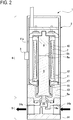
- FIG. 2 is a sectional view of the fluid control valve 1 in a valve closed state.
- FIG. 3 is a sectional view of the fluid control valve 1 in a valve closed state where a foreign substance A flows into a fluid.
- the fluid control valve 1 includes, as shown in FIG. 1 , a valve main body 2 and a vibration sensor 3 for detecting vibration of the valve main body 2.
- the valve main body 2 includes an actuator section 4 and a valve section 5.
- the actuator section 4 is provided with a fixed iron core 8 and a movable iron core 9 (an example of a "movable member") coaxially arranged in a hollow coil bobbin 10.
- An excitation coil 7 is wound around the coil bobbin 10.
- One end surface 8a (a lower surface in FIG. 1 ) of the fixed iron core 8 is a pole face, and this pole face is coaxially opposed to one end surface 9b (an upper surface in FIG. 1 ) of the movable iron core 9.
- the fixed iron core 8 has an outside diameter approximately equal to the inside diameter of the coil bobbin 10.
- the excitation coil 7 is circumferentially surrounded by a yoke 11.
- the yoke 11 is covered with a mold part 12. Under a lower end of the mold part 12, a connecting member 13 is placed in connection with the valve section 5.
- a lower end of the movable iron core 9 is formed with a flange 9a extending radially outwardly.
- the flange 9a retains one end of a spring 15 which urges a diaphragm valve element (hereinafter, simply referred to as a "valve element") 16 described later in a direction to contact with a valve seat 14a.
- the other end of the spring 15 abuts on a spring receiving member 17 placed between the yoke 11 and the connecting member 13.
- the valve section 5 includes a passage block 14 formed with an inlet passage 14b and an outlet passage 14c.
- the valve seat 14a is formed at a center of the passage block 14, with which the valve element 16 will come into or out of contact.
- the excitation coil 7 is not energized. Accordingly, the movable iron core 9 is separated from the fixed iron core 8, and the valve element 16 is held in contact with the valve seat 14a by the urging force of the spring 15. Thus, the inlet passage 14b is out of communication with the outlet passage 14c.
- FIG. 13 is a control block diagram of the vibration sensor 3.
- the vibration sensor 3 has a chip shape of a predetermined size (e.g., several mm square), and is soldered on a board (not shown).
- the board attached with the vibration sensor 3 is mounted in the valve main body 2, at a position where vibration generated in the valve main body 2 which will be described later can be detected.
- the vibration sensor 3 is directly attached to a side surface 11a of the yoke 11 and partly covered with the mold part 12.
- a controller 6 one example of an "abnormality determining unit" is attached.
- the controller 6 includes a CPU 20 and a ROM 18.
- the ROM 18 has an abnormality determining program 19 stored.
- the abnormality decision program 19 is performed by the controller 6 (one example of an "abnormality determining unit") to determine whether the valve main body 2 works normally or abnormally.
- the controller 6 is connected with a display device 21 which displays whether the valve main body 2 works normally or abnormally.
- a detecting vibration direction which the vibration sensor 3 can detect is one. It is therefore most preferable to dispose the vibration sensor 3 in an orientation having the detecting vibration direction adjusted to an actual vibration direction.
- the vibration generated by motion of the movable iron core 9 is also transmitted to the side surface 11a of the yoke 11.
- the vibration sensor 3 having the detecting vibration direction adjusted to the actual vibrating direction can detect the vibration. Even if the actual vibration direction is oblique with respect to the vibration sensor 3, this sensor 3 can also detect such vibration.
- FIG. 4 is a graph showing a relationship between vibration S, voltage P, and time T ("S-P-T relationship") under a condition where the fluid control valve 1 is normal (no foreign substances are present in a fluid) and the pressure of the fluid flowing through the fluid control valve 1, i.e., the fluid pressure, is 0.0 MPa.
- FIG. 5 is a graph showing the S-P-T relationship under a condition where the fluid control valve 1 is abnormal (some foreign substances are present in a fluid) and the fluid pressure is 0.0 MPa.
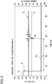
- FIG. 6 is a graph showing the S-P-T relationship under a condition where the fluid control valve 1 is normal (no foreign substances are present in a fluid) and the fluid pressure is 0.3 MPa.
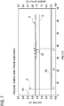
- FIG. 7 is a graph showing the S-P-T relationship under a condition where the fluid control valve 1 is abnormal (some foreign substances are present in a fluid) and the fluid pressure is 0.3 MPa.
- a vertical axis represents solenoid valve voltage [V] indicating the pressure P, and vibration sensor output [V] indicating the vibration S.
- a horizontal axis represents the time T [ms].
- the abnormal state of the fluid control valve 1 (some foreign substances are present in the fluid) in FIGs. 5 and 7 is the foreign substances A flow into a passage (the inlet passage 14b and the outlet passage 14c) of the valve section 5 as shown in FIG. 3 .
- the vibration S3 is generated by the water hammer phenomenon and, as shown in FIG. 6 , the vibration S3 is produced with an amplitude exceeding a threshold X after a time T1 passes.
- the threshold X has been set in advance according to production or use conditions.
- the valve main body 2 is determined to be normal based on the abnormality determining program 19. This determination result, indicating that the valve main body 2 is normal, is displayed on the display device 21.
- the vibration S4 is generated by the water hammer phenomenon, but this vibration S4 is produced with an amplitude not exceeding the threshold X even after the time T1 passes.
- the vibration sensor 3 detects the vibration S4 having an amplitude not exceeding the threshold X, so that the valve main body 2 is determined to be abnormal based on the abnormality determining program 19. This determination result, indicating that the valve main body 2 is abnormal, is displayed on the display device 21.
- the reason why the amplitude of the vibration S4 does not exceed the threshold X when some foreign substances are present and a leak occurs lies in that, if any foreign substances are present between the valve element 16 and the valve seat 14a, a slight clearance or gap is created therebetween thereby forming a passage.
- This passage allows a fluid to flow in the outlet passage 14c just after valve closing and thus a small negative pressure is only generated, resulting in a small amplitude of the vibration S4 produced by the water hammer phenomenon.
- By utilizing the phenomenon it is possible to detect even a slight leakage based on a detection result of the vibration even when a threadlike foreign substance has a thickness of about 100 ⁇ m.
- the pressure of the fluid in the outlet passage 14c changes, by a small difference, from a negative pressure to a positive pressure after valve closing. Therefore, even if there are any foreign substances and any clearance, the fluid is not caused to flow through the clearance.
- the valve element 16 is brought in contact with the valve seat 14a by the urging force of the spring 15, therefore, the vibrations S1 and S2 with amplitudes exceeding the threshold X are generated.
- the fluid control valve is configured to detect the leak caused by a threadlike foreign substance suddenly getting between the valve element 16 and the valve seat 14a.
- the fluid control valve can also detect any leak caused by precipitate of the fluid, deterioration of seal portions of the valve element and the valve seat, or deterioration of the movable iron core.
- the valve main body 2 is not closed and hence the magnitude of vibration descends. In this case, accordingly, abnormality of the valve main body 2 can also be detected. Furthermore, since the sensor 3 does not need to be installed in the passage (a wetted part), there is no influence on the fluid to be used. Also, since the vibration sensor 3 is installed in the valve main body 2, there is no need to install additional sensors such as a flow meter, a pressure gauge, a thermometer, etc. before and after the fluid control valve 1 in order to detect the leak, so that the fluid control valve 1 can be reduced in size.
- FIG. 8 is a graph showing a relationship between vibration S, voltage P, and time T under the condition where the voltage is 70% (this 70% voltage means 70% of the rated voltage of the valve main body 2.
- FIG. 9 is a graph showing a relationship between vibration S, voltage P, and time T under the condition where the voltage is 80%.
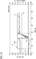
- FIG. 10 is a graph showing a relationship between vibration S, voltage P, and time T under the condition where the voltage is 90%.
- FIG. 11 and FIG. 12 are graphs to explain the delay of the response time due to an increase in the sliding resistance.
- FIG. 11 is a graph showing a relationship between vibration S, voltage P, and time when there is no sliding resistance
- FIG. 12 is a graph showing a relationship between vibration S, voltage P, and time T when the sliding resistance increases.
- a vertical axis represents solenoid valve pressure [V] indicating pressure P
- vibration sensor output [V] indicating vibration S
- a horizontal axis represents time [ms].
- the vibration S generated at the time of valve opening is not caused by the water hammer phenomenon occurring just after valve closing, but is caused by the collision of the movable iron core 9 with the fixed iron core 8.
- the vibration S5 with an amplitude exceeding the threshold X is generated when the movable iron core 9 comes into contact with the fixed iron core 8. Then, under the condition where the voltage P is 80% (voltage P6), after a lapse of the time T3 shorter than the time T2, the vibration S6 with an amplitude exceeding the threshold X is generated. Further, under the condition where the voltage is 90% (voltage P 8), after a lapse of the time T4 shorter than the time T3, the vibration S7 with an amplitude exceeding the threshold X is generated.
- the sliding resistance is increased in a sliding part of the movable iron core 9 (i.e., a contact surface with an inner wall of the coil bobbin 10) by aging wear of the movable iron core 9.
- the motion of the movable iron core 9 delays (T6 - T5) when the sliding resistance is increased in FIG. 12 (vibration S8). This delay in motion of the movable iron core 9 appears as in the case when the voltage P drops. That is, the higher the sliding resistance is, the slower the motion of the movable iron core 9 is.
- the fluid control valve 1 in the present embodiment can provide the following operations and effects.
- valve main body 2 is a solenoid valve in this embodiment, however, other types of fluid control valve may be used, such as a pilot valve driven with air.
- the vibration sensor 3 in this embodiment is a sensor to detect the vibration, however, instead of the vibration sensor, an accelerator sensor to detect an acceleration speed may be used.
- the vibration sensor 3 in this embodiment is positioned at the side surface 11a of the yoke 11, however, the position where it is possible to detect the vibration may be used.
- the vibration sensor 3 may be installed on a bottom surface (an outer surface) of the passage block 14. The vibration is generated when the valve element 16 contacts with the valve seat 14a, so that it can be detected by attaching it to the bottom surface of the passage block 14. The attachment may be also embedded in the passage block 14.
- the vibration sensor 3 may be installed on an upper surface of the yoke 11 inside the fluid control valve 1. It is easy to detect the vibration caused by the motion of the movable core 9.
- the yoke 11 is a metal member and the vibration sensor 3 can directly detect the vibration. It is possible to incorporate the sensors into products.
Landscapes
- Engineering & Computer Science (AREA)
- General Engineering & Computer Science (AREA)
- Mechanical Engineering (AREA)
- Physics & Mathematics (AREA)
- General Physics & Mathematics (AREA)
- Electromagnetism (AREA)
- Indication Of The Valve Opening Or Closing Status (AREA)
- Details Of Valves (AREA)
- Measurement Of Mechanical Vibrations Or Ultrasonic Waves (AREA)
Abstract
Description
- The present invention relates to a fluid control valve with a sensor including a valve main body having an actuator section and a valve section, the actuator part being configured to move a movable member, the valve section being formed with a valve seat with which a valve element of the movable member will come into or out of contact, and a vibration sensor for detecting vibration of the valve main body.
- Conventionally, a fluid control valve for medical liquid in a medical analysis device is used to control various kinds of fluids such as a reagent, a dilute solution, and a cleaning solution. As the fluid control valve, there is proposed a fluid control valve disclosed in
Patent Document 1 configured to check whether or not allowing/stopping a flow of the fluid is definitely performed in the fluid control valve. This fluid control valve inPatent Document 1 is equipped with a vibration sensor to detect a sound generated in the control valve during operation, and determine the presence/absence of an operation failure by comparing the sound with a normal sound to determine whether the fluid is flowing or is shut off. - Patent Document 1: Japanese Patent No.
5399687 - However, the conventional fluid control valve only detects the operation failure of the control valve, and cannot detect a leak at a valve closing part. When this valve is used in a medical analysis device, for example, the fluid may be deposited on or adhered to the valve closing part, leading to clogging at the valve closing part, thereby developing a leak therefrom. Especially, in a blood testing device, if protein of a sample is accumulated on a sealing surface of a valve closing part, a leak occurs at the valve closing part, which may cause false detection.
- Moreover, a drive source of the control valve, such as a solenoid, an air cylinder, or a motor, may slow down because of durability operation, thereby causing a valve opening/closing force to weaken. Further, sudden inflow of some foreign substances or the like into a fluid flowing through a passage or wear of a valve section for opening and closing a passage of the control valve may block the valve section from appropriately closing. This may develop a leak at the valve closing part.
- In order to detect the leak at the valve closing part, some valves are attached with sensors, such as a flowmeter, a pressure gauge, and a thermometer, which are arranged before and behind the control valve. However, those sensors need space to be arranged, leading to an increased size of the device. Also, for such a device, it is difficult to detect a slight leak caused by foreign substances with a diameter as small as the thickness of a human (adult) hair (about 100 µm). Further, these sensors need to be placed inside of a passage; however, a device for treating several kinds of fluids has restricted materials for parts to be wetted (wetted parts). Therefore, it is preferable to minimize the number of the wetted parts.
- The present invention has been made to solve the above problems and has the purpose to provide a fluid control valve to detect a slight leak at a valve closing part of the fluid control valve.
- To achieve the above purpose, one aspect of the invention provides a fluid control valve with a sensor, including: a valve main body including: an actuator section provided with a movable member including a valve element and configured to move the movable member; and a valve section provided with a valve seat with which the valve element will come into or out of contact; and a vibration sensor which detects vibration generated in the valve main body. The vibration is generated by a water hammer phenomenon that generates impact when the valve element comes into contact with the valve seat and no fluid leaks between the valve element and the valve seat. The fluid control valve further includes an abnormality determining unit configured to determine the valve main body to be normal when the vibration sensor detects the vibration with an amplitude exceeding a predetermined threshold, and determine the valve main body to be abnormal when the vibration sensor does not detect the vibration with an amplitude exceeding the predetermined threshold.
Further developments of the present invention are given in the dependent claims. - According to the above configuration, by utilizing the water hammer phenomenon the fluid control valve can detect a slight leak at the valve closing part by detecting the vibrations with an amplitude not exceeding the threshold.
-
-
FIG. 1 is a sectional view of a fluid control valve in a valve closed state; -
FIG. 2 is a sectional view of the fluid control valve in a valve open state; -
FIG. 3 is a sectional view of the fluid control valve in a valve closed state where foreign substances flow into a fluid; -
FIG. 4 is a graph showing a relationship between vibration, voltage, and time under a condition where the fluid pressure is 0.0 MPa and the fluid control valve is normal (no foreign substances); -
FIG. 5 is a graph showing a relationship between vibration, voltage, and time under a condition where the fluid pressure is 0.0 MPa and the fluid control valve is abnormal (some foreign substances); -
FIG. 6 is a graph showing a relationship between vibration, voltage, and time under a condition where the fluid pressure is 0.3 MPa and the fluid control valve is normal (no foreign substances); -
FIG. 7 is a graph showing a relationship between vibration, voltage, and time under a condition where the fluid pressure is 0.3 MPa and the fluid control valve is abnormal (some foreign substances); -
FIG. 8 is a graph showing a relationship between vibration, voltage, and time under a condition where the voltage is 70%; -
FIG. 9 is a graph showing a relationship between vibration, voltage, and time under a condition where the voltage is 80%; -
FIG. 10 is a graph showing a relationship between vibration, voltage, and time under a condition where the voltage is 90%; -
FIG. 11 is a graph showing a relationship between vibration, voltage, and time when there is no sliding resistance; -
FIG. 12 is a graph showing a relationship between vibration, voltage, and time when the sliding resistance increases; and -
FIG. 13 is a control block diagram of a vibration sensor. - A detailed description of a preferred embodiment of a fluid control valve with a sensor according to the present invention will now be given referring to the accompanying drawings.
- Explanation is given to a structure of a fluid control valve with a sensor (hereinafter, also referred to as a "sensor-equipped fluid control valve" or simply a "fluid control valve") 1, referring to
FIGs. 1 to 3 .FIG. 1 is a sectional view of thefluid control valve 1 in a valve open state.FIG. 2 is a sectional view of thefluid control valve 1 in a valve closed state.FIG. 3 is a sectional view of thefluid control valve 1 in a valve closed state where a foreign substance A flows into a fluid. - The
fluid control valve 1 includes, as shown inFIG. 1 , a valvemain body 2 and avibration sensor 3 for detecting vibration of the valvemain body 2. The valvemain body 2 includes anactuator section 4 and avalve section 5. Theactuator section 4 is provided with a fixediron core 8 and a movable iron core 9 (an example of a "movable member") coaxially arranged in ahollow coil bobbin 10. Anexcitation coil 7 is wound around thecoil bobbin 10. Oneend surface 8a (a lower surface inFIG. 1 ) of the fixediron core 8 is a pole face, and this pole face is coaxially opposed to oneend surface 9b (an upper surface inFIG. 1 ) of themovable iron core 9. The fixediron core 8 has an outside diameter approximately equal to the inside diameter of thecoil bobbin 10. Theexcitation coil 7 is circumferentially surrounded by ayoke 11. Theyoke 11 is covered with amold part 12. Under a lower end of themold part 12, a connectingmember 13 is placed in connection with thevalve section 5. - A lower end of the
movable iron core 9 is formed with aflange 9a extending radially outwardly. Theflange 9a retains one end of aspring 15 which urges a diaphragm valve element (hereinafter, simply referred to as a "valve element") 16 described later in a direction to contact with avalve seat 14a. The other end of thespring 15 abuts on aspring receiving member 17 placed between theyoke 11 and the connectingmember 13. - The
valve section 5 includes apassage block 14 formed with aninlet passage 14b and anoutlet passage 14c. Thevalve seat 14a is formed at a center of thepassage block 14, with which thevalve element 16 will come into or out of contact. - In the state shown in
FIG. 1 , theexcitation coil 7 is not energized. Accordingly, themovable iron core 9 is separated from the fixediron core 8, and thevalve element 16 is held in contact with thevalve seat 14a by the urging force of thespring 15. Thus, theinlet passage 14b is out of communication with theoutlet passage 14c. - On the other hand, when the
excitation coil 7 is energized, themovable iron core 9 is attracted into contact with the fixediron core 8. Thus, as shown inFIG. 2 , thediaphragm element 16 is moved apart from thevalve seat 14a, and theinlet passage 14b is communicated with theoutlet passage 14c. - Next, the
vibration sensor 3 will be explained below.FIG. 13 is a control block diagram of thevibration sensor 3. Thevibration sensor 3 has a chip shape of a predetermined size (e.g., several mm square), and is soldered on a board (not shown). The board attached with thevibration sensor 3 is mounted in the valvemain body 2, at a position where vibration generated in the valvemain body 2 which will be described later can be detected. In this embodiment, thevibration sensor 3 is directly attached to aside surface 11a of theyoke 11 and partly covered with themold part 12. On the board, a controller 6 (one example of an "abnormality determining unit") is attached. Thecontroller 6 includes aCPU 20 and aROM 18. TheROM 18 has anabnormality determining program 19 stored. Theabnormality decision program 19 is performed by the controller 6 (one example of an "abnormality determining unit") to determine whether the valvemain body 2 works normally or abnormally. Thecontroller 6 is connected with adisplay device 21 which displays whether the valvemain body 2 works normally or abnormally. - A detecting vibration direction which the
vibration sensor 3 can detect is one. It is therefore most preferable to dispose thevibration sensor 3 in an orientation having the detecting vibration direction adjusted to an actual vibration direction. In this embodiment, the vibration generated by motion of themovable iron core 9 is also transmitted to theside surface 11a of theyoke 11. Thus, thevibration sensor 3 having the detecting vibration direction adjusted to the actual vibrating direction can detect the vibration. Even if the actual vibration direction is oblique with respect to thevibration sensor 3, thissensor 3 can also detect such vibration. - Next, the effects in the
fluid control valve 1 in the closed state will be explained withFIG. 4 to FIG. 7 .FIG. 4 is a graph showing a relationship between vibration S, voltage P, and time T ("S-P-T relationship") under a condition where thefluid control valve 1 is normal (no foreign substances are present in a fluid) and the pressure of the fluid flowing through thefluid control valve 1, i.e., the fluid pressure, is 0.0 MPa.FIG. 5 is a graph showing the S-P-T relationship under a condition where thefluid control valve 1 is abnormal (some foreign substances are present in a fluid) and the fluid pressure is 0.0 MPa.FIG. 6 is a graph showing the S-P-T relationship under a condition where thefluid control valve 1 is normal (no foreign substances are present in a fluid) and the fluid pressure is 0.3 MPa.FIG. 7 is a graph showing the S-P-T relationship under a condition where thefluid control valve 1 is abnormal (some foreign substances are present in a fluid) and the fluid pressure is 0.3 MPa. In the graphs ofFIG. 4 to FIG. 7 , a vertical axis represents solenoid valve voltage [V] indicating the pressure P, and vibration sensor output [V] indicating the vibration S. A horizontal axis represents the time T [ms]. The abnormal state of the fluid control valve 1 (some foreign substances are present in the fluid) inFIGs. 5 and7 is the foreign substances A flow into a passage (theinlet passage 14b and theoutlet passage 14c) of thevalve section 5 as shown inFIG. 3 . - When energization of the
excitation coil 7 is stopped and hence the pressure P in thecontrol valve 1 decreases from P1 to P2, themovable iron core 9 is moved downward by the force of thespring 15, bringing thevalve element 16 into contact withvalve seat 14a. At that time, the water hammer phenomenon occurs. - Herein, the water hammer phenomenon will be explained. When the
valve element 16 in the valvemain body 2 is abruptly moved to a closed position, the fluid flowing from theinlet passage 14b toward theoutlet passage 14c strikes or impinges on the passage wall of theinlet passage 14b by an inertia force of the fluid. This impingement of the fluid generates the water hammer phenomenon, which makes an impulsive sound. This water hammer phenomenon produces the vibration S. This vibration S is detected by thevibration sensor 3. - Under the condition where the fluid pressure is 0.3 MPa, when no foreign substances are present between the
valve element 16 and thevalve seat 14 and thus no fluid leaks therebetween, the vibration S3 is generated by the water hammer phenomenon and, as shown inFIG. 6 , the vibration S3 is produced with an amplitude exceeding a threshold X after a time T1 passes. The threshold X has been set in advance according to production or use conditions. Thus, the valvemain body 2 is determined to be normal based on theabnormality determining program 19. This determination result, indicating that the valvemain body 2 is normal, is displayed on thedisplay device 21. - When some foreign substances are present between the
valve element 16 and thevalve seat 14a and a resultant leak occurs, as shown inFIG. 7 , the vibration S4 is generated by the water hammer phenomenon, but this vibration S4 is produced with an amplitude not exceeding the threshold X even after the time T1 passes. Thus, thevibration sensor 3 detects the vibration S4 having an amplitude not exceeding the threshold X, so that the valvemain body 2 is determined to be abnormal based on theabnormality determining program 19. This determination result, indicating that the valvemain body 2 is abnormal, is displayed on thedisplay device 21. - Herein, the reason why the amplitude of the vibration S4 does not exceed the threshold X when some foreign substances are present and a leak occurs lies in that, if any foreign substances are present between the
valve element 16 and thevalve seat 14a, a slight clearance or gap is created therebetween thereby forming a passage. This passage allows a fluid to flow in theoutlet passage 14c just after valve closing and thus a small negative pressure is only generated, resulting in a small amplitude of the vibration S4 produced by the water hammer phenomenon. By utilizing the phenomenon, it is possible to detect even a slight leakage based on a detection result of the vibration even when a threadlike foreign substance has a thickness of about 100 µm. - On the other hand, under the condition where the fluid pressure is around 0.0 MPa, when no foreign substances are present between the
valve element 16 and thevalve seat 14 and thus no fluid leaks therebetween, as shown inFIG. 4 , after a time T0 passes, the vibration S1 is generated by thevalve element 16 when contacting thevalve seat 14a with the urging force of thespring 15. The amplitude of this vibration S1 exceeds the predetermined threshold X. - However, under the condition where the fluid pressure is around 0.0 MPa, even if any foreign substances are present and a leak occurs, as is the case that any foreign substances are not present, the
valve element 16 comes into contact with thevalve seat 14a by the urging force of thespring 15 after T0 passes, so that the vibration S2 is generated with an amplitude exceeding the threshold X as shown inFIG. 5 . Under the condition where the fluid pressure is around 0.0 MPa, it is impossible to detect the abnormal state of the valvemain body 2 based on the vibration S. That is because, under the condition where the fluid pressure is around 0.0 MPa, the flow velocity of the fluid is low and hence the fluid hardly flows. For such a low flow velocity, the pressure of the fluid in theoutlet passage 14c changes, by a small difference, from a negative pressure to a positive pressure after valve closing. Therefore, even if there are any foreign substances and any clearance, the fluid is not caused to flow through the clearance. When thevalve element 16 is brought in contact with thevalve seat 14a by the urging force of thespring 15, therefore, the vibrations S1 and S2 with amplitudes exceeding the threshold X are generated. - Under the condition where the fluid pressure is 0.0 MPa (no fluid flows), the water hammer phenomenon does not occur. When the fluid pressure is 0.0 MPa, the
valve element 16 is brought in contact with thevalve seat 14a by the urging force of thespring 15, thereby generating vibration. However, under the condition where the fluid pressure is 0.3 MPa (a fluid flows), the fluid exerts a force on thevalve element 16 in a direction to push it up (i.e., a force against the urging force), thus preventing a large impact at the time of seating of thevalve element 16 on thevalve seat 14a. Therefore, the faster the flow is, the stronger the water hammer phenomenon is. However, when any foreign substance is caused between thevalve seat 14a and thevalve element 16 or a sealing surface of thevalve seat 14a is defective, the fluid is caused to flow from a clearance formed around the foreign substance. Thus, a small water hammer occurs. - In this embodiment, the fluid control valve is configured to detect the leak caused by a threadlike foreign substance suddenly getting between the
valve element 16 and thevalve seat 14a. In addition, the fluid control valve can also detect any leak caused by precipitate of the fluid, deterioration of seal portions of the valve element and the valve seat, or deterioration of the movable iron core. - Also, at the time of generation of vibrations during operation (due to jamming or stick-slip of the movable iron core), the valve
main body 2 is not closed and hence the magnitude of vibration descends. In this case, accordingly, abnormality of the valvemain body 2 can also be detected. Furthermore, since thesensor 3 does not need to be installed in the passage (a wetted part), there is no influence on the fluid to be used. Also, since thevibration sensor 3 is installed in the valvemain body 2, there is no need to install additional sensors such as a flow meter, a pressure gauge, a thermometer, etc. before and after thefluid control valve 1 in order to detect the leak, so that thefluid control valve 1 can be reduced in size. - Next, the effects of the
fluid control valve 1 in the valve open state will be explained withFIG. 8 to FIG. 12 .FIG. 8 is a graph showing a relationship between vibration S, voltage P, and time T under the condition where the voltage is 70% (this 70% voltage means 70% of the rated voltage of the valvemain body 2. The same applies to the following.)
FIG. 9 is a graph showing a relationship between vibration S, voltage P, and time T under the condition where the voltage is 80%.FIG. 10 is a graph showing a relationship between vibration S, voltage P, and time T under the condition where the voltage is 90%.FIG. 11 andFIG. 12 are graphs to explain the delay of the response time due to an increase in the sliding resistance.FIG. 11 is a graph showing a relationship between vibration S, voltage P, and time when there is no sliding resistance, andFIG. 12 is a graph showing a relationship between vibration S, voltage P, and time T when the sliding resistance increases. In each graph, a vertical axis represents solenoid valve pressure [V] indicating pressure P, and vibration sensor output [V] indicating vibration S, and a horizontal axis represents time [ms]. The vibration S generated at the time of valve opening is not caused by the water hammer phenomenon occurring just after valve closing, but is caused by the collision of themovable iron core 9 with the fixediron core 8. - When the
excitation coil 7 is electrically energized (a voltage changes: P3 → P4 inFIG. 8 , P5 → P6 inFIG. 9 , and P7 → P8 inFIG. 10 ), themovable iron core 9 is attracted into contact with the fixediron core 8. Accordingly, theelement valve 16 is moved away from thevalve seat 14a. - Under the condition where the voltage P is 70% (voltage P4), after the time T2 passes, the vibration S5 with an amplitude exceeding the threshold X is generated when the
movable iron core 9 comes into contact with the fixediron core 8. Then, under the condition where the voltage P is 80% (voltage P6), after a lapse of the time T3 shorter than the time T2, the vibration S6 with an amplitude exceeding the threshold X is generated. Further, under the condition where the voltage is 90% (voltage P 8), after a lapse of the time T4 shorter than the time T3, the vibration S7 with an amplitude exceeding the threshold X is generated. - Comparing the heights of the voltage P with the length of the time T, the higher the voltage P is (P4 < P6 < P8), the shorter the response time T is (T2 > T3 > T4). The lower the voltage P is, the longer the response time T is.
- Then, wear detection for the
movable iron core 9 will be explained withFIGs. 11 and12 . In the valvemain body 2, the sliding resistance is increased in a sliding part of the movable iron core 9 (i.e., a contact surface with an inner wall of the coil bobbin 10) by aging wear of themovable iron core 9. Compared with the case where there is no sliding resistance inFIG. 11 (vibration S7), the motion of themovable iron core 9 delays (T6 - T5) when the sliding resistance is increased inFIG. 12 (vibration S8). This delay in motion of themovable iron core 9 appears as in the case when the voltage P drops. That is, the higher the sliding resistance is, the slower the motion of themovable iron core 9 is. Further, the higher the sliding resistance is, the longer the response time to the valve fully open is. Accordingly, detecting the delay in motion of themovable iron core 9 when the response time exceeds a predetermined time, i.e. a threshold Y, that is, when the vibration S is not detected within the predetermined time, an increase in the sliding resistance can be estimated. For example, when the response time exceeds the threshold Y, it is possible to determine replacement timing for a product and to perform preventive maintenance of lifetime of the product. Also, since vibration is low or is not generated even if themovable iron core 9 stops on the way, it is possible to detect abnormality of the valvemain body 2. - As described above, the
fluid control valve 1 in the present embodiment can provide the following operations and effects. - (1) The
fluid control valve 1 includes the valvemain body 2 and thevibration sensor 3. The valvemain body 2 includes theactuator section 4 and thevalve section 5. Theactuator section 4 is provided with themovable iron core 9 including thevalve element 16 and configured to move themovable iron core 9. Thevalve section 5 is provided with thevalve seat 14a with which thevalve element 16 will come into or out of contact. Thevibration sensor 3 detects the vibration S generated in the valvemain body 2. The vibration S is generated by a water hammer phenomenon. The water hammer phenomenon generates impact when thevalve element 16 comes into contact with thevalve seat 14a and no fluid leaks between thevalve element 16 and thevalve seat 14a. Thefluid control valve 1 further includes the controller 6 (the abnormality determining program 19). Thefluid control valve 1 determines the valvemain body 2 to be normal when thesensor 3 detects the vibration S with an amplitude exceeding the predetermined threshold X, and determines the valvemain body 2 to be abnormal when thesensor 3 does not detect the vibration S with an amplitude exceeding the predetermined threshold X. Accordingly, by utilizing the water hammer phenomenon thefluid control valve 1 can detect a slight leak at the valve closing part of the valvemain body 2 by detecting the vibration S with an amplitude not exceeding the threshold X. - (2) In the
fluid control valve 1 described in (1), thevibration sensor 3 is specialized in detecting the impact. Accordingly, it is possible for thevibration sensor 3 to detect a slight impact. Therefore, thefluid control valve 1 can detect the vibration S generated by a slight impact by the water hammer phenomenon, and it can definitely detect a slight leak at the valve closing part of the valvemain body 2. - (3) In the
fluid control valve 1 described in (1) or (2), thevibration sensor 3 is located in a position where the vibration S can be detected. Accordingly, the vibration S is transmitted to the valvemain body 2 entirely, therefore, it is possible to attach thevibration sensor 3 to anywhere in the valvemain body 2. - (4) In the
fluid control valve 1 described in one of (1) to (3), thecontroller 6 determines the valvemain body 2 to be abnormal based on a detection result of the vibration, even when the leak is caused by threadlike foreign substances. Accordingly, thefluid control valve 1 can definitely detect a slight leak caused by the threadlike foreign substances having a thickness of about 100 µm. - (5) In the
fluid control valve 1 described in one of (1) or (4), thecontroller 6 determines the valvemain body 2 to be abnormal when the vibration S is not detected within a predetermined time (the threshold Y). Accordingly, since the sliding resistance is increased in the sliding part of themovable iron core 9, the response time to the valve fully open is long. Therefore, it is possible to determine replacement timing for the valvemain body 2 by time-sequentially looking. - The present invention may be embodied in other specific forms without departing from the essential characteristics thereof.
- For example, the valve
main body 2 is a solenoid valve in this embodiment, however, other types of fluid control valve may be used, such as a pilot valve driven with air. - The
vibration sensor 3 in this embodiment is a sensor to detect the vibration, however, instead of the vibration sensor, an accelerator sensor to detect an acceleration speed may be used. - The
vibration sensor 3 in this embodiment is positioned at theside surface 11a of theyoke 11, however, the position where it is possible to detect the vibration may be used. - Also, the
vibration sensor 3 may be installed on a bottom surface (an outer surface) of thepassage block 14. The vibration is generated when thevalve element 16 contacts with thevalve seat 14a, so that it can be detected by attaching it to the bottom surface of thepassage block 14. The attachment may be also embedded in thepassage block 14. - Further, the
vibration sensor 3 may be installed on an upper surface of theyoke 11 inside thefluid control valve 1. It is easy to detect the vibration caused by the motion of themovable core 9. Theyoke 11 is a metal member and thevibration sensor 3 can directly detect the vibration. It is possible to incorporate the sensors into products. -
- 1
- Fluid control valve with sensor
- 2
- Valve main body
- 3
- Vibration sensor
- 4
- Actuator section
- 5
- Valve section
- 7
- Excitation coil
- 8
- Fixed iron core
- 9
- Movable iron core
- 14a
- Valve seat
- 16
- Diaphragm valve element
Claims (5)
- A fluid control valve with a sensor, comprising:a valve main body including:an actuator section provided with a movable member including a valve element and configured to move the movable member; anda valve section provided with a valve seat with which the valve element will come into or out of contact; anda vibration sensor which detects vibration generated in the valve main body,wherein the vibration is generated by a water hammer phenomenon that generates impact when the valve element comes into contact with the valve seat and no fluid leaks between the valve element and the valve seat, andthe fluid control valve further includes an abnormality determining unit configured to determine the valve main body to be normal when the vibration sensor detects the vibration with an amplitude exceeding a predetermined threshold, and determine the valve main body to be abnormal when the vibration sensor does not detect the vibration with an amplitude exceeding the predetermined threshold.
- The fluid control valve with the sensor according to claim 1, wherein the vibration sensor is specialized in detecting the impact.
- The fluid control valve with the sensor according to claim 1 or 2, wherein the vibration sensor is located in a position where the vibration can be detected.
- The fluid control valve with the sensor according to any one of claims 1 to 3, wherein the abnormality determining unit determines the valve main body to be abnormal based on a detection result of the vibration even when a leak of the fluid is caused by threadlike foreign substances.
- The fluid control valve with the sensor according to any one of claims 1 to 4, wherein the abnormality determining unit determines the valve main body to be abnormal when the vibration is not detected within a predetermined time.
Applications Claiming Priority (1)
| Application Number | Priority Date | Filing Date | Title |
|---|---|---|---|
| JP2016129207A JP6674340B2 (en) | 2016-06-29 | 2016-06-29 | Fluid control valve with sensor |
Publications (2)
| Publication Number | Publication Date |
|---|---|
| EP3263963A1 true EP3263963A1 (en) | 2018-01-03 |
| EP3263963B1 EP3263963B1 (en) | 2019-05-29 |
Family
ID=59269817
Family Applications (1)
| Application Number | Title | Priority Date | Filing Date |
|---|---|---|---|
| EP17178585.0A Active EP3263963B1 (en) | 2016-06-29 | 2017-06-29 | Fluid control valve with sensor |
Country Status (5)
| Country | Link |
|---|---|
| US (1) | US20180003317A1 (en) |
| EP (1) | EP3263963B1 (en) |
| JP (1) | JP6674340B2 (en) |
| KR (1) | KR20180002527A (en) |
| CN (1) | CN107542937B (en) |
Cited By (3)
| Publication number | Priority date | Publication date | Assignee | Title |
|---|---|---|---|---|
| CN108426682A (en) * | 2018-03-16 | 2018-08-21 | 天津英创汇智汽车技术有限公司 | The airtight measuring device of inlet valve and its measurement method |
| EP3851713A1 (en) * | 2020-01-20 | 2021-07-21 | SISTO Armaturen S.A. | System for condition monitoring |
| US12404860B2 (en) | 2021-11-17 | 2025-09-02 | Grundfos Holding A/S | Method and apparatus for detecting hydraulic shock |
Families Citing this family (7)
| Publication number | Priority date | Publication date | Assignee | Title |
|---|---|---|---|---|
| US10544876B2 (en) * | 2018-04-18 | 2020-01-28 | Chin-Yuan Chen | Solenoid valve for irrigation systems |
| JP7271303B2 (en) * | 2019-05-16 | 2023-05-11 | Ckd株式会社 | fluid control valve |
| US11313482B2 (en) | 2019-11-14 | 2022-04-26 | Entegris, Inc. | Welded check valve |
| JP7320473B2 (en) * | 2020-03-27 | 2023-08-03 | Ckd株式会社 | butterfly valve |
| JP2022104380A (en) * | 2020-12-28 | 2022-07-08 | 日本電産トーソク株式会社 | solenoid valve |
| JP7580303B2 (en) * | 2021-03-04 | 2024-11-11 | 三菱重工サーマルシステムズ株式会社 | Anomaly detection system, determination device, anomaly detection method, determination method, and program |
| DE112022005273T5 (en) * | 2021-11-04 | 2024-08-14 | Parker-Hannifin Corporation | Media-isolated miniature rocker diaphragm valve with reinforced magnetic flux circuit |
Citations (9)
| Publication number | Priority date | Publication date | Assignee | Title |
|---|---|---|---|---|
| US5008841A (en) * | 1989-07-28 | 1991-04-16 | Liberty Technology Center, Inc. | Non-invasive system and method for inspection of valves |
| US5616829A (en) * | 1995-03-09 | 1997-04-01 | Teledyne Industries Inc. | Abnormality detection/suppression system for a valve apparatus |
| JP2002181229A (en) * | 2000-12-12 | 2002-06-26 | Tomoe Tech Res Co | Actuator for valve |
| WO2004102052A1 (en) * | 2003-05-16 | 2004-11-25 | Siemens Aktiengesellschaft | Diagnostic system and method for a valve, especially a check valve of a positive displacement pump |
| WO2007072602A1 (en) * | 2005-12-21 | 2007-06-28 | Kabushiki Kaisha Fujikin | Water hammer-less valve |
| GB2497994A (en) * | 2011-12-30 | 2013-07-03 | Spirax Sarco Ltd | Monitoring a steam plant |
| JP5399687B2 (en) | 2008-11-14 | 2014-01-29 | 関東化学株式会社 | Air operated valve diagnosis method and air operated valve |
| JP2014173852A (en) * | 2013-03-05 | 2014-09-22 | Fuji Tecom Inc | Leak sound detector |
| WO2016038527A1 (en) * | 2014-09-08 | 2016-03-17 | Universidad De Medellín | Device and method for fluid leakage detection in pressurized pipes |
Family Cites Families (9)
| Publication number | Priority date | Publication date | Assignee | Title |
|---|---|---|---|---|
| JPS60179586A (en) * | 1984-02-28 | 1985-09-13 | Nippon Atom Ind Group Co Ltd | Monitor for valve gear |
| JPH06323945A (en) * | 1993-05-11 | 1994-11-25 | Tohoku Electric Power Co Inc | Valve leak detector |
| CN2313129Y (en) * | 1997-10-18 | 1999-04-07 | 李汉宝 | Piston guide type electromagnetic valve |
| JP4501487B2 (en) * | 2004-03-25 | 2010-07-14 | 株式会社デンソー | Solenoid valve drive inspection method |
| CN201229375Y (en) * | 2008-07-23 | 2009-04-29 | 樱花卫厨(中国)股份有限公司 | Solenoid valve closed current detector |
| US8457908B2 (en) * | 2009-06-11 | 2013-06-04 | University Of Washington | Sensing events affecting liquid flow in a liquid distribution system |
| CN201795887U (en) * | 2010-09-01 | 2011-04-13 | 华南理工大学 | Pressure sensor |
| JP2013140576A (en) * | 2011-12-30 | 2013-07-18 | Spirax-Sarco Ltd | Apparatus for monitoring steam plant and operating method thereof |
| US9759213B2 (en) * | 2015-07-28 | 2017-09-12 | Computational Systems, Inc. | Compressor valve health monitor |
-
2016
- 2016-06-29 JP JP2016129207A patent/JP6674340B2/en active Active
-
2017
- 2017-06-22 US US15/630,070 patent/US20180003317A1/en not_active Abandoned
- 2017-06-27 KR KR1020170081000A patent/KR20180002527A/en not_active Ceased
- 2017-06-29 EP EP17178585.0A patent/EP3263963B1/en active Active
- 2017-06-29 CN CN201710518029.2A patent/CN107542937B/en active Active
Patent Citations (10)
| Publication number | Priority date | Publication date | Assignee | Title |
|---|---|---|---|---|
| US5008841A (en) * | 1989-07-28 | 1991-04-16 | Liberty Technology Center, Inc. | Non-invasive system and method for inspection of valves |
| US5008841B1 (en) * | 1989-07-28 | 1995-09-19 | Liberty Technologies Inc | Non-invasive system and method for inspection of valves |
| US5616829A (en) * | 1995-03-09 | 1997-04-01 | Teledyne Industries Inc. | Abnormality detection/suppression system for a valve apparatus |
| JP2002181229A (en) * | 2000-12-12 | 2002-06-26 | Tomoe Tech Res Co | Actuator for valve |
| WO2004102052A1 (en) * | 2003-05-16 | 2004-11-25 | Siemens Aktiengesellschaft | Diagnostic system and method for a valve, especially a check valve of a positive displacement pump |
| WO2007072602A1 (en) * | 2005-12-21 | 2007-06-28 | Kabushiki Kaisha Fujikin | Water hammer-less valve |
| JP5399687B2 (en) | 2008-11-14 | 2014-01-29 | 関東化学株式会社 | Air operated valve diagnosis method and air operated valve |
| GB2497994A (en) * | 2011-12-30 | 2013-07-03 | Spirax Sarco Ltd | Monitoring a steam plant |
| JP2014173852A (en) * | 2013-03-05 | 2014-09-22 | Fuji Tecom Inc | Leak sound detector |
| WO2016038527A1 (en) * | 2014-09-08 | 2016-03-17 | Universidad De Medellín | Device and method for fluid leakage detection in pressurized pipes |
Cited By (4)
| Publication number | Priority date | Publication date | Assignee | Title |
|---|---|---|---|---|
| CN108426682A (en) * | 2018-03-16 | 2018-08-21 | 天津英创汇智汽车技术有限公司 | The airtight measuring device of inlet valve and its measurement method |
| CN108426682B (en) * | 2018-03-16 | 2020-06-05 | 天津英创汇智汽车技术有限公司 | Suction valve airtightness measuring device and measuring method thereof |
| EP3851713A1 (en) * | 2020-01-20 | 2021-07-21 | SISTO Armaturen S.A. | System for condition monitoring |
| US12404860B2 (en) | 2021-11-17 | 2025-09-02 | Grundfos Holding A/S | Method and apparatus for detecting hydraulic shock |
Also Published As
| Publication number | Publication date |
|---|---|
| KR20180002527A (en) | 2018-01-08 |
| EP3263963B1 (en) | 2019-05-29 |
| US20180003317A1 (en) | 2018-01-04 |
| CN107542937A (en) | 2018-01-05 |
| CN107542937B (en) | 2019-12-06 |
| JP6674340B2 (en) | 2020-04-01 |
| JP2018003912A (en) | 2018-01-11 |
Similar Documents
| Publication | Publication Date | Title |
|---|---|---|
| EP3263963B1 (en) | Fluid control valve with sensor | |
| US8265794B2 (en) | Knowledge based valve control method | |
| EP2721331B1 (en) | Method of monitoring a solenoid-operated valve | |
| US9176156B2 (en) | Automatic analyzer including pressure sensor for washing solution | |
| US20110260085A1 (en) | Solenoid Valve With Sensor For Determining Stroke, Velocities And/Or Accelerations Of A Moveable Core Of The Valve As Indication Of Failure Modus And Health Status | |
| CN208294882U (en) | Via the device of the solenoid valve of locator test emergency valve | |
| EP3529499B1 (en) | Methods and apparatus of stabilizing a valve positioner when testing a solenoid valve | |
| US7908912B2 (en) | Oil sensing system for an internal combustion engine | |
| KR20090124618A (en) | Solenoid Valve Test Apparatus And Method | |
| US10746119B2 (en) | Pressure determination in a fuel injection valve | |
| KR101836085B1 (en) | Fluid leakage self-diagnosis system | |
| JP2019529768A (en) | Functional monitoring of solenoid valves for fuel injectors | |
| KR101277693B1 (en) | Fluid flow control valve | |
| CN112005037A (en) | Method for monitoring the function of a control valve, device for carrying out said method, and control valve having said device | |
| US12085186B2 (en) | Valve and fluid control device with a magnetic indicator | |
| US7068027B1 (en) | System for measurement of metallic debris in fluid | |
| JP2005273835A (en) | Solenoid valve drive inspection method and solenoid valve | |
| JP2011039019A (en) | Superconductive sensor for electromagnetic diagnostic apparatus | |
| JP7271303B2 (en) | fluid control valve | |
| JP2007255251A (en) | Device for and method of determining failure of egr control valve | |
| JP2003050177A (en) | Gas leak inspection method and gas meter for implementing the same | |
| JP7010771B2 (en) | Overflow blocking valve and overflow blocking valve inspection device | |
| JP3378129B2 (en) | Gas meter | |
| JP4687485B2 (en) | Inspection method and inspection device for quality defect of linear control valve | |
| JP4117743B2 (en) | Gas shut-off device |
Legal Events
| Date | Code | Title | Description |
|---|---|---|---|
| PUAI | Public reference made under article 153(3) epc to a published international application that has entered the european phase |
Free format text: ORIGINAL CODE: 0009012 |
|
| STAA | Information on the status of an ep patent application or granted ep patent |
Free format text: STATUS: REQUEST FOR EXAMINATION WAS MADE |
|
| 17P | Request for examination filed |
Effective date: 20170629 |
|
| AK | Designated contracting states |
Kind code of ref document: A1 Designated state(s): AL AT BE BG CH CY CZ DE DK EE ES FI FR GB GR HR HU IE IS IT LI LT LU LV MC MK MT NL NO PL PT RO RS SE SI SK SM TR |
|
| AX | Request for extension of the european patent |
Extension state: BA ME |
|
| RBV | Designated contracting states (corrected) |
Designated state(s): AL AT BE BG CH CY CZ DE DK EE ES FI FR GB GR HR HU IE IS IT LI LT LU LV MC MK MT NL NO PL PT RO RS SE SI SK SM TR |
|
| REG | Reference to a national code |
Ref country code: DE Ref legal event code: R079 Ref document number: 602017004187 Country of ref document: DE Free format text: PREVIOUS MAIN CLASS: F16K0037000000 Ipc: G01H0003140000 |
|
| GRAP | Despatch of communication of intention to grant a patent |
Free format text: ORIGINAL CODE: EPIDOSNIGR1 |
|
| STAA | Information on the status of an ep patent application or granted ep patent |
Free format text: STATUS: GRANT OF PATENT IS INTENDED |
|
| RIC1 | Information provided on ipc code assigned before grant |
Ipc: G01H 3/14 20060101AFI20190108BHEP Ipc: F16K 37/00 20060101ALI20190108BHEP Ipc: F16K 7/14 20060101ALI20190108BHEP Ipc: F16K 31/06 20060101ALI20190108BHEP |
|
| INTG | Intention to grant announced |
Effective date: 20190124 |
|
| GRAS | Grant fee paid |
Free format text: ORIGINAL CODE: EPIDOSNIGR3 |
|
| GRAA | (expected) grant |
Free format text: ORIGINAL CODE: 0009210 |
|
| STAA | Information on the status of an ep patent application or granted ep patent |
Free format text: STATUS: THE PATENT HAS BEEN GRANTED |
|
| AK | Designated contracting states |
Kind code of ref document: B1 Designated state(s): AL AT BE BG CH CY CZ DE DK EE ES FI FR GB GR HR HU IE IS IT LI LT LU LV MC MK MT NL NO PL PT RO RS SE SI SK SM TR |
|
| REG | Reference to a national code |
Ref country code: GB Ref legal event code: FG4D |
|
| REG | Reference to a national code |
Ref country code: CH Ref legal event code: EP |
|
| REG | Reference to a national code |
Ref country code: AT Ref legal event code: REF Ref document number: 1138548 Country of ref document: AT Kind code of ref document: T Effective date: 20190615 |
|
| REG | Reference to a national code |
Ref country code: DE Ref legal event code: R096 Ref document number: 602017004187 Country of ref document: DE |
|
| REG | Reference to a national code |
Ref country code: IE Ref legal event code: FG4D |
|
| REG | Reference to a national code |
Ref country code: NL Ref legal event code: MP Effective date: 20190529 |
|
| REG | Reference to a national code |
Ref country code: LT Ref legal event code: MG4D |
|
| PG25 | Lapsed in a contracting state [announced via postgrant information from national office to epo] |
Ref country code: LT Free format text: LAPSE BECAUSE OF FAILURE TO SUBMIT A TRANSLATION OF THE DESCRIPTION OR TO PAY THE FEE WITHIN THE PRESCRIBED TIME-LIMIT Effective date: 20190529 Ref country code: ES Free format text: LAPSE BECAUSE OF FAILURE TO SUBMIT A TRANSLATION OF THE DESCRIPTION OR TO PAY THE FEE WITHIN THE PRESCRIBED TIME-LIMIT Effective date: 20190529 Ref country code: SE Free format text: LAPSE BECAUSE OF FAILURE TO SUBMIT A TRANSLATION OF THE DESCRIPTION OR TO PAY THE FEE WITHIN THE PRESCRIBED TIME-LIMIT Effective date: 20190529 Ref country code: PT Free format text: LAPSE BECAUSE OF FAILURE TO SUBMIT A TRANSLATION OF THE DESCRIPTION OR TO PAY THE FEE WITHIN THE PRESCRIBED TIME-LIMIT Effective date: 20190930 Ref country code: HR Free format text: LAPSE BECAUSE OF FAILURE TO SUBMIT A TRANSLATION OF THE DESCRIPTION OR TO PAY THE FEE WITHIN THE PRESCRIBED TIME-LIMIT Effective date: 20190529 Ref country code: NO Free format text: LAPSE BECAUSE OF FAILURE TO SUBMIT A TRANSLATION OF THE DESCRIPTION OR TO PAY THE FEE WITHIN THE PRESCRIBED TIME-LIMIT Effective date: 20190829 Ref country code: FI Free format text: LAPSE BECAUSE OF FAILURE TO SUBMIT A TRANSLATION OF THE DESCRIPTION OR TO PAY THE FEE WITHIN THE PRESCRIBED TIME-LIMIT Effective date: 20190529 Ref country code: AL Free format text: LAPSE BECAUSE OF FAILURE TO SUBMIT A TRANSLATION OF THE DESCRIPTION OR TO PAY THE FEE WITHIN THE PRESCRIBED TIME-LIMIT Effective date: 20190529 |
|
| PG25 | Lapsed in a contracting state [announced via postgrant information from national office to epo] |
Ref country code: GR Free format text: LAPSE BECAUSE OF FAILURE TO SUBMIT A TRANSLATION OF THE DESCRIPTION OR TO PAY THE FEE WITHIN THE PRESCRIBED TIME-LIMIT Effective date: 20190830 Ref country code: LV Free format text: LAPSE BECAUSE OF FAILURE TO SUBMIT A TRANSLATION OF THE DESCRIPTION OR TO PAY THE FEE WITHIN THE PRESCRIBED TIME-LIMIT Effective date: 20190529 Ref country code: RS Free format text: LAPSE BECAUSE OF FAILURE TO SUBMIT A TRANSLATION OF THE DESCRIPTION OR TO PAY THE FEE WITHIN THE PRESCRIBED TIME-LIMIT Effective date: 20190529 Ref country code: BG Free format text: LAPSE BECAUSE OF FAILURE TO SUBMIT A TRANSLATION OF THE DESCRIPTION OR TO PAY THE FEE WITHIN THE PRESCRIBED TIME-LIMIT Effective date: 20190829 |
|
| REG | Reference to a national code |
Ref country code: AT Ref legal event code: MK05 Ref document number: 1138548 Country of ref document: AT Kind code of ref document: T Effective date: 20190529 |
|
| PG25 | Lapsed in a contracting state [announced via postgrant information from national office to epo] |
Ref country code: CZ Free format text: LAPSE BECAUSE OF FAILURE TO SUBMIT A TRANSLATION OF THE DESCRIPTION OR TO PAY THE FEE WITHIN THE PRESCRIBED TIME-LIMIT Effective date: 20190529 Ref country code: SK Free format text: LAPSE BECAUSE OF FAILURE TO SUBMIT A TRANSLATION OF THE DESCRIPTION OR TO PAY THE FEE WITHIN THE PRESCRIBED TIME-LIMIT Effective date: 20190529 Ref country code: RO Free format text: LAPSE BECAUSE OF FAILURE TO SUBMIT A TRANSLATION OF THE DESCRIPTION OR TO PAY THE FEE WITHIN THE PRESCRIBED TIME-LIMIT Effective date: 20190529 Ref country code: AT Free format text: LAPSE BECAUSE OF FAILURE TO SUBMIT A TRANSLATION OF THE DESCRIPTION OR TO PAY THE FEE WITHIN THE PRESCRIBED TIME-LIMIT Effective date: 20190529 Ref country code: DK Free format text: LAPSE BECAUSE OF FAILURE TO SUBMIT A TRANSLATION OF THE DESCRIPTION OR TO PAY THE FEE WITHIN THE PRESCRIBED TIME-LIMIT Effective date: 20190529 Ref country code: NL Free format text: LAPSE BECAUSE OF FAILURE TO SUBMIT A TRANSLATION OF THE DESCRIPTION OR TO PAY THE FEE WITHIN THE PRESCRIBED TIME-LIMIT Effective date: 20190529 Ref country code: EE Free format text: LAPSE BECAUSE OF FAILURE TO SUBMIT A TRANSLATION OF THE DESCRIPTION OR TO PAY THE FEE WITHIN THE PRESCRIBED TIME-LIMIT Effective date: 20190529 |
|
| PG25 | Lapsed in a contracting state [announced via postgrant information from national office to epo] |
Ref country code: SM Free format text: LAPSE BECAUSE OF FAILURE TO SUBMIT A TRANSLATION OF THE DESCRIPTION OR TO PAY THE FEE WITHIN THE PRESCRIBED TIME-LIMIT Effective date: 20190529 Ref country code: MC Free format text: LAPSE BECAUSE OF FAILURE TO SUBMIT A TRANSLATION OF THE DESCRIPTION OR TO PAY THE FEE WITHIN THE PRESCRIBED TIME-LIMIT Effective date: 20190529 |
|
| REG | Reference to a national code |
Ref country code: DE Ref legal event code: R097 Ref document number: 602017004187 Country of ref document: DE |
|
| REG | Reference to a national code |
Ref country code: BE Ref legal event code: MM Effective date: 20190630 |
|
| PG25 | Lapsed in a contracting state [announced via postgrant information from national office to epo] |
Ref country code: TR Free format text: LAPSE BECAUSE OF FAILURE TO SUBMIT A TRANSLATION OF THE DESCRIPTION OR TO PAY THE FEE WITHIN THE PRESCRIBED TIME-LIMIT Effective date: 20190529 |
|
| PLBE | No opposition filed within time limit |
Free format text: ORIGINAL CODE: 0009261 |
|
| STAA | Information on the status of an ep patent application or granted ep patent |
Free format text: STATUS: NO OPPOSITION FILED WITHIN TIME LIMIT |
|
| PG25 | Lapsed in a contracting state [announced via postgrant information from national office to epo] |
Ref country code: PL Free format text: LAPSE BECAUSE OF FAILURE TO SUBMIT A TRANSLATION OF THE DESCRIPTION OR TO PAY THE FEE WITHIN THE PRESCRIBED TIME-LIMIT Effective date: 20190529 Ref country code: IE Free format text: LAPSE BECAUSE OF NON-PAYMENT OF DUE FEES Effective date: 20190629 |
|
| 26N | No opposition filed |
Effective date: 20200303 |
|
| PG25 | Lapsed in a contracting state [announced via postgrant information from national office to epo] |
Ref country code: SI Free format text: LAPSE BECAUSE OF FAILURE TO SUBMIT A TRANSLATION OF THE DESCRIPTION OR TO PAY THE FEE WITHIN THE PRESCRIBED TIME-LIMIT Effective date: 20190529 Ref country code: BE Free format text: LAPSE BECAUSE OF NON-PAYMENT OF DUE FEES Effective date: 20190630 Ref country code: LU Free format text: LAPSE BECAUSE OF NON-PAYMENT OF DUE FEES Effective date: 20190629 |
|
| REG | Reference to a national code |
Ref country code: CH Ref legal event code: PL |
|
| PG25 | Lapsed in a contracting state [announced via postgrant information from national office to epo] |
Ref country code: CH Free format text: LAPSE BECAUSE OF NON-PAYMENT OF DUE FEES Effective date: 20200630 Ref country code: LI Free format text: LAPSE BECAUSE OF NON-PAYMENT OF DUE FEES Effective date: 20200630 |
|
| PG25 | Lapsed in a contracting state [announced via postgrant information from national office to epo] |
Ref country code: CY Free format text: LAPSE BECAUSE OF FAILURE TO SUBMIT A TRANSLATION OF THE DESCRIPTION OR TO PAY THE FEE WITHIN THE PRESCRIBED TIME-LIMIT Effective date: 20190529 |
|
| PG25 | Lapsed in a contracting state [announced via postgrant information from national office to epo] |
Ref country code: IS Free format text: LAPSE BECAUSE OF FAILURE TO SUBMIT A TRANSLATION OF THE DESCRIPTION OR TO PAY THE FEE WITHIN THE PRESCRIBED TIME-LIMIT Effective date: 20190929 |
|
| PG25 | Lapsed in a contracting state [announced via postgrant information from national office to epo] |
Ref country code: HU Free format text: LAPSE BECAUSE OF FAILURE TO SUBMIT A TRANSLATION OF THE DESCRIPTION OR TO PAY THE FEE WITHIN THE PRESCRIBED TIME-LIMIT; INVALID AB INITIO Effective date: 20170629 Ref country code: MT Free format text: LAPSE BECAUSE OF FAILURE TO SUBMIT A TRANSLATION OF THE DESCRIPTION OR TO PAY THE FEE WITHIN THE PRESCRIBED TIME-LIMIT Effective date: 20190529 |
|
| PG25 | Lapsed in a contracting state [announced via postgrant information from national office to epo] |
Ref country code: MK Free format text: LAPSE BECAUSE OF FAILURE TO SUBMIT A TRANSLATION OF THE DESCRIPTION OR TO PAY THE FEE WITHIN THE PRESCRIBED TIME-LIMIT Effective date: 20190529 |
|
| PGFP | Annual fee paid to national office [announced via postgrant information from national office to epo] |
Ref country code: DE Payment date: 20250507 Year of fee payment: 9 |
|
| PGFP | Annual fee paid to national office [announced via postgrant information from national office to epo] |
Ref country code: GB Payment date: 20250508 Year of fee payment: 9 |
|
| PGFP | Annual fee paid to national office [announced via postgrant information from national office to epo] |
Ref country code: IT Payment date: 20250522 Year of fee payment: 9 |
|
| PGFP | Annual fee paid to national office [announced via postgrant information from national office to epo] |
Ref country code: FR Payment date: 20250508 Year of fee payment: 9 |