EP3263914A1 - Servo-valve and fluidic device - Google Patents
Servo-valve and fluidic device Download PDFInfo
- Publication number
- EP3263914A1 EP3263914A1 EP17177984.6A EP17177984A EP3263914A1 EP 3263914 A1 EP3263914 A1 EP 3263914A1 EP 17177984 A EP17177984 A EP 17177984A EP 3263914 A1 EP3263914 A1 EP 3263914A1
- Authority
- EP
- European Patent Office
- Prior art keywords
- inflow port
- port
- discharge port
- nozzle
- valve
- Prior art date
- Legal status (The legal status is an assumption and is not a legal conclusion. Google has not performed a legal analysis and makes no representation as to the accuracy of the status listed.)
- Granted
Links
Images






Classifications
-
- F—MECHANICAL ENGINEERING; LIGHTING; HEATING; WEAPONS; BLASTING
- F15—FLUID-PRESSURE ACTUATORS; HYDRAULICS OR PNEUMATICS IN GENERAL
- F15B—SYSTEMS ACTING BY MEANS OF FLUIDS IN GENERAL; FLUID-PRESSURE ACTUATORS, e.g. SERVOMOTORS; DETAILS OF FLUID-PRESSURE SYSTEMS, NOT OTHERWISE PROVIDED FOR
- F15B13/00—Details of servomotor systems ; Valves for servomotor systems
- F15B13/02—Fluid distribution or supply devices characterised by their adaptation to the control of servomotors
- F15B13/04—Fluid distribution or supply devices characterised by their adaptation to the control of servomotors for use with a single servomotor
- F15B13/042—Fluid distribution or supply devices characterised by their adaptation to the control of servomotors for use with a single servomotor operated by fluid pressure
- F15B13/043—Fluid distribution or supply devices characterised by their adaptation to the control of servomotors for use with a single servomotor operated by fluid pressure with electrically-controlled pilot valves
- F15B13/0436—Fluid distribution or supply devices characterised by their adaptation to the control of servomotors for use with a single servomotor operated by fluid pressure with electrically-controlled pilot valves the pilot valves being of the steerable jet type
-
- F—MECHANICAL ENGINEERING; LIGHTING; HEATING; WEAPONS; BLASTING
- F16—ENGINEERING ELEMENTS AND UNITS; GENERAL MEASURES FOR PRODUCING AND MAINTAINING EFFECTIVE FUNCTIONING OF MACHINES OR INSTALLATIONS; THERMAL INSULATION IN GENERAL
- F16K—VALVES; TAPS; COCKS; ACTUATING-FLOATS; DEVICES FOR VENTING OR AERATING
- F16K31/00—Actuating devices; Operating means; Releasing devices
- F16K31/02—Actuating devices; Operating means; Releasing devices electric; magnetic
- F16K31/04—Actuating devices; Operating means; Releasing devices electric; magnetic using a motor
-
- F—MECHANICAL ENGINEERING; LIGHTING; HEATING; WEAPONS; BLASTING
- F15—FLUID-PRESSURE ACTUATORS; HYDRAULICS OR PNEUMATICS IN GENERAL
- F15B—SYSTEMS ACTING BY MEANS OF FLUIDS IN GENERAL; FLUID-PRESSURE ACTUATORS, e.g. SERVOMOTORS; DETAILS OF FLUID-PRESSURE SYSTEMS, NOT OTHERWISE PROVIDED FOR
- F15B11/00—Servomotor systems without provision for follow-up action; Circuits therefor
- F15B11/08—Servomotor systems without provision for follow-up action; Circuits therefor with only one servomotor
Definitions
- the present invention relates to a servo-valve and a fluidic device having a high response performance.
- US Patent No. 2884907 discloses a technique of displacing a nozzle toward left and right sides of a rotation axis based on an electromagnetic principle to adjust the amount of hydraulic oil flowing into two inflow ports formed in a receiver.
- a high response speed of the servo-valve results in a high accuracy of a control using the servo-valve.
- various attempts for improving a mechanical mechanism and/or an electrical mechanism for driving the nozzle face various problems involving with a selection of a material, a mechanical strength, a complex control, and a manufacturing cost of the servo-valve.
- An object of the invention is to provide a simple technique of giving a high response speed to a servo-valve.
- a servo-valve controls a fluid discharged from a discharge port of a nozzle by displacing the nozzle and drives an actuator.
- the servo-valve includes a receiver provided with an inflow port into which the fluid discharged from the discharge port flows. At least one of the discharge port and the inflow port is an opening formed in a non-circular form such that the amount of change in the area of overlapping of the discharge port and the inflow port occurring when the nozzle is displaced from the initial position is larger than when the discharge port and the inflow port are formed in circular forms of the same area.
- the change amount of the area of overlapping of the discharge port and the inflow port occurring when the nozzle is displaced from the initial position is larger than that of a case in which the opening is formed in a circular form in the same area. Accordingly, since the fluid can flow into the inflow port in a short time, a response speed of the actuator is improved.
- a fluidic device includes the servo-valve and a movable piece which is displaced by the fluid in a hollow portion communicating with the first outflow port and the second outflow port.
- the fluidic device including the servo-valve can be operated at a high response speed.
- a discharge port formed in a nozzle and an inflow port formed in a receiver both have a circular form.
- a form of a discharge port or an inflow port (hereinafter, also referred to as an "opening") is changed to a non-circular form, an area of overlapping between the discharge port and the inflow port abruptly increases compared to a case in which the opening is circular under a short nozzle stroke (a nozzle movement amount).
- a servo-valve and an actuator driven by the servo-valve are operated with high responsiveness.
- an illustrative servo-valve capable of realizing a high response performance using a non-circular opening will be described.
- Fig. 1 is a conceptual diagram showing a servo-valve 100 of a first embodiment.
- the servo-valve 100 will be described with reference to Fig. 1 .
- Terms like “upward”, “downward”, “leftward”, “rightward”, “clockwise”, “counterclockwise”, “vertical”, and “horizontal” indicating directions are used merely for the purpose of making the explanation unambiguous. The principle of the embodiments is not by any means limited by these terms denoting the directions.
- the servo-valve 100 includes a nozzle 200, a receiver 300, and a driving unit 400.
- the driving unit 400 turns (swings) (hereinafter, referred to as “oscillation movement” or “oscillation”) a front end of the nozzle 200 in both directions (clockwise and counterclockwise) within a predetermined angle range about a rotation axis RAX defined at an upper portion of the nozzle 200.
- the driving unit 400 may be a general torque motor which gives a rotational force (a turning force) to the nozzle 200 using an electromagnetic force or other driving devices.
- the principle of the embodiment is not limited to a specific device used as the driving unit 400.
- the nozzle 200 includes an upper surface 210 and a lower surface 220.
- the lower surface 220 faces the receiver 300.
- the upper surface 210 is located above the lower surface 220.
- the upper surface 210 is provided with an inflow port 211.
- the inflow port 211 is connected to a pump or other fluid supply sources supplying a hydraulic fluid.
- the hydraulic fluid (which will be referred to as, for example, hydraulic oil, but may be simply referred to as a "fluid" on the condition that the invention is not limited thereto) flows into the nozzle 200 through the inflow port 211.
- the lower surface 220 (the front end surface) is provided with a discharge port 221.
- the nozzle 200 is provided with a nozzle flow path 230 which extends downward from the inflow port 211 and is coupled to the discharge port 221.
- the nozzle flow path 230 becomes narrow toward the discharge port 221.
- the hydraulic fluid which flows from the inflow port 211 into the nozzle 200 flows downward along the nozzle flow path 230 and is discharged from the discharge port 221. Subsequently, the hydraulic fluid flows into the receiver 300.
- the receiver 300 includes an upper surface (an opposite surface) 310 which faces the lower surface 220 of the nozzle 200.
- the upper surface 310 is provided with a left inflow port 311 and a right inflow port 312.
- Each of the left inflow port 311 and the right inflow port 312 is formed to be larger than the discharge port 221.
- the receiver 300 is provided with a left flow path 313 and a right flow path 314.
- the left flow path 313 extends leftward and downward from the left inflow port 311 and is terminated at the left outflow port 315.
- the right flow path 314 extends rightward and downward from the right inflow port 312 and is terminated at the right outflow port 316.
- the left outflow port 315 and the right outflow port 316 are formed in an outer surface of the receiver 300 and are coupled to a spool valve (not shown) or an actuator (not shown).
- a position of the nozzle 200 when a center axis of the nozzle flow path 230 (an axis line connecting a center of the inflow port 211 and a center of the discharge port 221) matches a vertical axis will be referred to as an "initial position".
- the hydraulic fluid discharged from the discharge port 221 flow in substantially in the same quantity into the left inflow port 311 and the right inflow port 312.
- the first inflow port is exemplified by one of the left inflow port 311 and the right inflow port 312.
- the second inflow port is exemplified by the other of the left inflow port 311 and the right inflow port 312.
- the discharge port 221 moves leftward.
- the area of overlapping between the discharge port 221 and the left inflow port 311 increases and the area of overlapping between the discharge port 221 and the right inflow port 312 decreases.
- the hydraulic fluid mainly flows into the left inflow port 311.
- the hydraulic fluid which flows into the left inflow port 311 flows out of the left outflow port 315 to drive the spool valve or the actuator. All this while, the spool valve or the actuator extrudes the hydraulic fluid stored therein.
- the hydraulic fluid which is extruded by the spool valve or the actuator flows from the right outflow port 316 into the right flow path 314.
- the hydraulic fluid which flows into the right flow path 314 flows from the right inflow port 312 to a gap between the lower surface 220 of the nozzle 200 and the upper surface 310 of the receiver 300.
- the hydraulic fluid which flows into the gap between the lower surface 220 of the nozzle 200 and the upper surface 310 of the receiver 300 may be returned to a predetermined storage tank.
- the discharge port 221 moves rightward.
- the area of overlapping between the discharge port 221 and the right inflow port 312 increases and the area of overlapping between the discharge port 221 and the left inflow port 311 decreases.
- the hydraulic fluid mainly flows into the right inflow port 312.
- the hydraulic fluid which flows into the right inflow port 312 flows out of the right outflow port 316 to drive the spool valve or the actuator. All this while, the spool valve or the actuator extrudes the hydraulic fluid stored therein.
- the hydraulic fluid which is extruded by the spool valve or the actuator flows from the left outflow port 315 into the left flow path 313.
- the hydraulic fluid which flows into the left flow path 313 flows from the left inflow port 311 to a gap between the lower surface 220 of the nozzle 200 and the upper surface 310 of the receiver 300.
- the hydraulic fluid which flows into the gap between the lower surface 220 of the nozzle 200 and the upper surface 310 of the receiver 300 may be returned to a predetermined storage tank.
- the first direction is exemplified by one of left and right directions.
- the discharge port 221 may be a non-circular opening.
- the left inflow port 311 and the right inflow port 312 may be circular openings or non-circular openings.
- the discharge port 221 may be a circular opening.
- at least one of the left inflow port 311 and the right inflow port 312 is a non-circular opening.
- Fig. 2 shows an illustrative form of the discharge port 221. Referring to Figs. 1 and 2 , a form of the discharge port 221 will be described.
- the section (a) of Fig. 2 shows a discharge port DH1 of a known nozzle.
- the sections (b) to (d) of Fig. 2 respectively indicate discharge ports DH2, DH3, and DH4 which can be used as the discharge port 221 described with reference to Fig. 1 .
- the discharge port DH1 is circular.
- the discharge port DH1 includes an area S0.
- the diameter of the discharge port DH1 is indicated by a sign "DM".
- the diameter of the virtual circle is exemplified by the diameter DM.
- the discharge port DH2 is rectangular. Like the discharge port DH1, the discharge port DH2 includes an area S0. In the section (b) of Fig. 2 , the width of the discharge port DH2 is indicated by a sign "W1". The width W1 of the discharge port DH2 may be defined as a dimension of the discharge port DH2 in the movement direction of the discharge port 221 or may be defined as a length of a short side of the discharge port DH2. As shown in the section (b) of Fig. 2 , the width W1 of the discharge port DH2 is smaller than the diameter DM of the discharge port DH1.
- the discharge port DH3 is elliptical. Like the discharge port DH1, the discharge port DH3 includes an area S0. In the section (c) of Fig. 2 , the width of the discharge port DH3 is indicated by a sign "W2". The width W2 of the discharge port DH3 may be defined as a dimension of the discharge port DH3 in the movement direction of the discharge port 221 or may be defined as a length of a short axis of the discharge port DH3. As shown in the section (c) of Fig. 2 , the width W2 of the discharge port DH3 is smaller than the diameter DM of the discharge port DH1.
- the discharge port DH4 has an elliptical form including two half arcs and two lines. Each of two lines extends in a direction orthogonal to the movement direction of the discharge port 221. Two lines are arranged in series in the movement direction of the discharge port 221. Two half arcs respectively connects ends of two lines.
- the discharge port DH4 includes an area S0.
- the width of the discharge port DH4 is indicated by a sign "W3".
- the width W3 of the discharge port DH4 may be defined as a dimension of the discharge port DH4 in the movement direction of the discharge port 221 or may be defined as a gap between the lines of the discharge port DH3. As shown in the section (d) of Fig. 2 , the width W3 of the discharge port DH4 is smaller than the diameter DM of the discharge port DH1.
- the sections (b) to (d) of Fig. 2 respectively indicate dimensions "L1", “L2", and "L3" of discharge ports DH2, DH3, and DH4 in the longitudinal direction defined as a direction orthogonal to the movement direction of the discharge port 221 and the discharge direction of the hydraulic fluid discharged from the discharge port 221 at the initial position.
- the areas of the discharge ports DH2, DH3, and DH4 are the same as that of the discharge port DH1 and the widths W1, W2, and W3 of the discharge ports DH2, DH3, and DH4 are respectively smaller than the diameter DM of the discharge port DH1.
- the length dimensions L1, L2, and L3 of the discharge ports DH2, DH3, and DH4 are respectively larger than the diameter DM of the discharge port DH1.
- the second direction is exemplified by the longitudinal direction.
- Each of the discharge ports DH2, DH3, and DH4 has a symmetrical form with respect to an axis extended in the longitudinal direction.
- the hydraulic fluid flows in substantially in the same quantity into the left inflow port 311 and the right inflow port 312 when the nozzle 200 is located at the initial position.
- Fig. 3 shows illustrative forms of the left inflow port 311 and the right inflow port 312. Referring to Figs. 1 and 3 , the forms of the left inflow port 311 and the right inflow port 312 will be described.
- the section (a) of Fig. 3 indicates a left inflow port IL1 and a right inflow port IR1 of a known receiver.
- the sections (b) to (e) of Fig. 3 respectively indicate left inflow ports IL2, IL3, IL4, and IL5 used as the left inflow port 311 and right inflow ports IR2, IR3, IR4, and IR5 used as the right inflow port 312 described with reference to Fig. 1 .
- Each of the left inflow port IL1 and the right inflow port IR1 is circular.
- Each of the left inflow port IL1 and the right inflow port IR1 includes an area S0.
- the diameter of each of the left inflow port IL1 and the right inflow port IR1 is indicated by a sign "DM".
- the diameter of the virtual circle is exemplified by the diameter DM.
- Each of the left inflow port IL2 and the right inflow port IR2 is rectangular. Like the left inflow port IL1, the left inflow port IL2 includes an area S0. Like the right inflow port IR1, the right inflow port IR2 includes an area S0. In the section (b) of Fig. 3 , the width of each of the left inflow port IL2 and the right inflow port IR2 is indicated by a sign "W1".
- the widths W1 of the left inflow port IL2 and the right inflow port IR2 may be respectively defined as dimensions of the left inflow port IL2 and the right inflow port IR2 in the movement direction of the discharge port 221 and may be defined as lengths of short sides of the left inflow port IL2 and the right inflow port IR2. As shown in the section (b) of Fig. 3 , the widths W1 of the left inflow port IL2 and the right inflow port IR2 are respectively smaller than the diameters DM of the left inflow port IL1 and the right inflow port IR1.
- Each of the left inflow port IL3 and the right inflow port IR3 is elliptical. Like the left inflow port IL1, the left inflow port IL3 includes an area S0. Like the left inflow port IL1, the right inflow port IR3 includes an area S0. In the section (c) of Fig. 3 , the widths of the left inflow port IL3 and the right inflow port IR3 are respectively indicated by a sign "W2".
- the widths W2 of the left inflow port IL3 and the right inflow port IR3 may be defined as the dimensions of the left inflow port IL3 and the right inflow port IR3 in the movement direction of the discharge port 221 and may be defined as lengths of short axes of the left inflow port IL3 and the right inflow port IR3. As shown in the section (c) of Fig. 3 , the widths W2 of the left inflow port IL3 and the right inflow port IR3 are respectively smaller than the diameters DM of the left inflow port IL1 and the right inflow port IR1.
- Each of the left inflow port IL4 and the right inflow port IR4 has an elliptical form including two half arcs and two lines. Each of two lines extends in a direction orthogonal to the movement direction of the discharge port 221. Two lines are arranged in series in the movement direction of the discharge port 221. Two half arcs respectively connect ends of two lines. Like the left inflow port IL1, the left inflow port IL4 includes an area S0. Like the right inflow port IR1, the right inflow port IR4 includes an area S0. In the section (d) of Fig. 3 , the widths of the left inflow port IL4 and the right inflow port IR4 are respectively indicated by a sign "W3".
- the widths W3 of the left inflow port IL4 and the right inflow port IR4 may be respectively defined as the dimensions of the left inflow port IL4 and the right inflow port IR4 in the movement direction of the discharge port 221 and may be defined as gaps between the lines of the left inflow port IL4 and the right inflow port IR4. As shown in the section (d) of Fig. 3 , the widths W3 of the left inflow port IL4 and the right inflow port IR4 are smaller than the diameter DM of the discharge port DH1.
- Each of the left inflow port IL5 and the right inflow port IR5 is triangular. Like the left inflow port IL1, the left inflow port IL5 includes an area S0. Like the right inflow port IR1, the right inflow port IR5 includes an area S0.
- the widths of the left inflow port IL5 and the right inflow port IR5 are indicated by a sign "W4".
- the widths W4 of the left inflow port IL5 and the right inflow port IR5 are respectively defined as the dimensions of the left inflow port IL5 and the right inflow port IR5 in the movement direction of the discharge port 221. As shown the section (d) of Fig. 3 , the widths W4 of the left inflow port IL5 and the right inflow port IR5 are smaller than the diameters DM of the left inflow port IL1 and the right inflow port IR1.
- the dimension of each of the left inflow port IL2 and the right inflow port IR2 in the longitudinal direction is indicated by "L1".
- the dimension of each of the left inflow port IL3 and the right inflow port IR3 in the longitudinal direction is indicated by "L2”.
- the dimension of each of the left inflow port IL4 and the right inflow port IR4 in the longitudinal direction is indicated by "L3”.
- the dimension of each of the left inflow port IL5 and the right inflow port IR5 in the longitudinal direction is indicated by "L4".
- the areas of the left inflow ports IL2, IL3, IL4, and IL5 and the right inflow ports IR2, IR3, IR4, and IR5 are respectively the same as those of the left inflow port IL1 and the right inflow port IR1 and the widths W1, W2, W3, and W4 of the left inflow ports IL2, IL3, IL4, and IL5 and the right inflow ports IR2, IR3, IR4, and IR5 are smaller than the diameters DM of the left inflow port IL1 and the right inflow port IR1.
- the length dimensions L1, L2, L3, and L4 of the left inflow ports IL2, IL3, IL4, and IL5 and the right inflow ports IR2, IR3, IR4, and IR5 are larger than the diameters DM of the left inflow port IL1 and the right inflow port IR1.
- the sections (b) to (e) of Fig. 3 show a point P.
- the point P is located on an extended line which passes through the center of the discharge port 221 of the nozzle 200 at the initial position and extends in the discharge direction of the hydraulic fluid discharged from the discharge port 221 of the nozzle 200 at the initial position.
- the point P shown in the section (b) of Fig. 3 is located at the midpoint of the line connecting the center of the left inflow port IL2 and the center of the right inflow port IR2.
- the left inflow port IL2 has a mirror image relation with respect to the right inflow port IR2 in a virtual plane (not shown) enclosing the line passing through the point P and extended in the longitudinal direction and the extended line extended in the discharge direction of the hydraulic fluid discharged from the discharge port 221 of the nozzle 200 located at the initial position.
- the point P shown in the section (c) of Fig. 3 is located at the midpoint of the line connecting the center of the left inflow port IL3 and the center of the right inflow port IR3.
- the left inflow port IL3 has a mirror image relation with respect to the right inflow port IR3 in the virtual plane (not shown) enclosing the line passing through the point P and extended in the longitudinal direction and the extended line extended in the discharge direction of the hydraulic fluid discharged from the discharge port 221 of the nozzle 200 located at the initial position.
- the point P shown in the section (d) of Fig. 3 is located at the midpoint of the line connecting the center of the left inflow port IL4 and the center of the right inflow port IR4.
- the left inflow port IL4 has a mirror image relation with respect to the right inflow port IR4 in the virtual plane (not shown) enclosing the line passing through the point P and extended in the longitudinal direction and the extended line extended in the discharge direction of the hydraulic fluid discharged from the discharge port 221 of the nozzle 200 located at the initial position.
- the point P shown in the section (e) of Fig. 3 is located at the midpoint of the line connecting the center of the left inflow port IL5 and the center of the right inflow port IR5.
- the left inflow port IL5 has a mirror image relation with respect to the right inflow port IR5 in the virtual plane (not shown) enclosing the line passing through the point P and extended in the longitudinal direction and the extended line extended in the discharge direction of the hydraulic fluid discharged from the discharge port 221 of the nozzle 200 located at the initial position.
- a servo-valve can have a high response performance when an area of overlapping between a discharge port and an inflow port changes greatly in response to the movement of a nozzle.
- an illustrative relation between the discharge port and the inflow port will be described.
- Fig. 4 is a conceptual diagram showing an illustrative relation of the discharge port 221, the left inflow port 311, and the right inflow port 312. Referring to Figs. 1 to 4 , the form of the discharge port 221 will be described.
- the section (a) of Fig. 4 shows a discharge port NH1, a left inflow port LH1, and a right inflow port RH1 of a known nozzle.
- the section (b) of Fig. 4 shows a discharge port NH2 which can be used as the discharge port 221 described with reference to Fig. 1 , a left inflow port LH2 which can be used as the left inflow port 311 described with reference to Fig. 1 , and a right inflow port RH2 which can be used as the right inflow port 312 described with reference to Fig. 1 .
- the section (c) of Fig. 4 shows a discharge port NH3 which can be used as the discharge port 221 described with reference to Fig.
- a left inflow port LH3 which can be used as the left inflow port 311 described with reference to Fig. 1
- a right inflow port RH3 which can be used as the right inflow port 312 described with reference to Fig. 1 .
- the areas of the left inflow port LH1 and the right inflow port RH1 are indicated by a sign "S1".
- the area of the discharge port NH1 is indicated by a sign "S2".
- the area S1 is larger than the area S2.
- One of the area S1 and the area S2 corresponds to the area S0 described with reference to Figs. 2 and 3 .
- the left inflow port LH2 shown in the section (b) of Fig. 4 includes an area S1.
- the right inflow port RH1 shown in the section (b) of Fig. 4 includes an area S1.
- the discharge port NH1 shown in the section (b) of Fig. 4 includes an area S2.
- the left inflow port LH3 shown in the section (c) of Fig. 4 includes an area S1.
- the right inflow port RH1 shown in the section (c) of Fig. 4 includes an area S1.
- the discharge port NH1 shown in the section (c) of Fig. 4 includes an area S2.
- the discharge port NH1 shown in the section (a) of Fig. 4 partially overlaps each of the left inflow port LH1 and the right inflow port RH1.
- the area of overlapping between the discharge port NH1 and the left inflow port LH1 is indicated by a sign "OL1".
- the area of overlapping between the discharge port NH1 and the right inflow port RH1 is indicated by a sign "OR1".
- the discharge port NH2 shown in the section (b) of Fig. 4 partially overlaps each of the left inflow port LH2 and the right inflow port RH2.
- the relative positional relation between the left inflow port LH2 and the discharge port NH2 is set so that the area of overlapping between the discharge port NH2 and the left inflow port LH2 matches the area of overlapping OL1.
- the relative positional relation between the right inflow port RH2 and the discharge port NH2 is set so that the area of overlapping between the discharge port NH2 and the right inflow port RH2 matches the area of overlapping OR1.
- the discharge port NH2 moves leftward, the area of overlapping OL1 increases and the area of overlapping OR1 decreases.
- the initial position may be exemplified by the position of the nozzle 200 which holds the positional relation shown in the section (b) of Fig. 4 .
- the discharge port NH3 shown in the section (c) of Fig. 4 partially overlaps the left inflow port LH3 and the right inflow port RH3.
- the relative positional relation between the left inflow port LH3 and the discharge port NH3 is set so that the area of overlapping between the discharge port NH3 and the left inflow port LH3 matches the area of overlapping OL1.
- the relative positional relation between the right inflow port RH3 and the discharge port NH3 is set so that the area of overlapping between the discharge port NH3 and the right inflow port RH3 matches the area of overlapping OR1.
- the initial position may be exemplified as the position of the nozzle 200 which holds the positional relation shown in the section (c) of Fig. 4 .
- Each of the left inflow port LH1 and the right inflow port RH1 shown in the section (a) of Fig. 4 has a circular form including a radius R1.
- the discharge port NH1 shown in the section (a) of Fig. 4 has a circular form including a radius R2 smaller than the radius R1.
- the curvature of each outline of the left inflow port LH1 and the right inflow port RH1 inside the discharge port NH1 is "1/R1".
- the curvature of the outline of the discharge port NH1 inside the left inflow port LH1 or the right inflow port RH1 is "1/R2".
- the virtual circle is exemplified by the circular form of each of the discharge port NH1, the left inflow port LH1, and the right inflow port RH1.
- Each of the discharge port NH2, the left inflow port LH2, and the right inflow port RH2 shown in the section (b) of Fig. 4 has a rectangular form in the longitudinal direction.
- the centers of the discharge port NH2, the left inflow port LH2, and the right inflow port RH2 are aligned in the movement direction of the discharge port NH2.
- a gap of a pair of short sides of each of the left inflow port LH2 and the right inflow port RH2 (a side extended in the movement direction of the discharge port NH2) is wider than a gap of a pair of short sides of the discharge port NH2 (a side extended in the movement direction of the discharge port NH2).
- each of long sides of the left inflow port LH2 and the right inflow port RH2 is enclosed in the discharge port NH2.
- a pair of long sides of the discharge port NH2 (a side extended in a direction orthogonal to the movement direction of the discharge port NH2) is enclosed in the left inflow port LH2 and the right inflow port RH2 on the whole. Since the curvature of the long side is zero, the curvature is smaller than the curvatures "1/R1" and "1/R2" described in the section (a) of Fig. 4 .
- the discharge port NH3 shown in the section (c) of Fig. 4 is shaped in an ellipse elongated in the longitudinal direction and each of the left inflow port LH3 and the right inflow port RH3 has a rectangular form elongated in the longitudinal direction.
- the centers of the discharge port NH3, the left inflow port LH3, and the right inflow port RH3 are aligned in the movement direction of the discharge port NH3.
- a gap of a pair of short sides of each of the left inflow port LH3 and the right inflow port RH3 (a side extended in the movement direction of the discharge port NH3) is wider than the long axis dimension of the discharge port NH3.
- the discharge port NH3 a part of long sides of the left inflow port LH3 and the right inflow port RH3 are enclosed in the discharge port NH3. Since the curvatures of the long sides are zero, the curvatures are smaller than the curvatures "1/R1" and "1/R2" described with reference to the section (a) of Fig. 4 .
- the outline having a small curvature ( ⁇ 1/R2) of the discharge port NH3 is located inside each of the left inflow port LH3 and the right inflow port RH3 and the outline having a large curvature (> 1/R2) of the discharge port NH3 is located between the left inflow port LH3 and the right inflow port RH3.
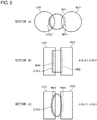
- Fig. 5 is a conceptual diagram showing a change in area of overlapping. Referring to Figs. 1 , 4 , and 5 , a change in area of overlapping will be described.
- the section (a) of Fig. 5 shows a change in area of overlapping between the discharge port NH1 and the left inflow port LH1 when the discharge port NH1 is displaced leftward.
- the discharge port NH1 indicated by a dotted line in the section (a) of Fig. 5 corresponds to the position of the discharge port NH1 described in the section (a) of Fig. 4 .
- the hatching area shown in the section (a) of Fig. 5 indicates an increment of the area of overlapping between the discharge port NH1 and the left inflow port LH1.
- An increment of the area of overlapping when the discharge port NH1 is displaced leftward is indicated by a sign " ⁇ OL1".
- the section (b) of Fig. 5 shows a change in area of overlapping between the discharge port NH2 and the left inflow port LH2 when the discharge port NH2 is displaced leftward.
- the discharge port NH2 indicated by a dotted line in the section (b) of Fig. 5 corresponds to the position of the discharge port NH2 described with respect to the section (b) of Fig. 4 .
- the leftward movement amount of the discharge port NH2 is the same as the leftward movement amount of the discharge port NH1.
- the hatching area shown in the section (b) of Fig. 5 indicates an increment of the area of overlapping between the discharge port NH2 and the left inflow port LH2.
- An increment of the area of overlapping when the discharge port NH2 is displaced leftward is indicated by a sign " ⁇ OL2".
- the increment ⁇ OL2 of the area of overlapping shown in the section (b) of Fig. 5 is larger than the increment ⁇ OL1 of the area of overlapping shown in the section (a) of Fig. 5 .
- the section (c) of Fig. 5 shows a change in area of overlapping between the discharge port NH3 and the left inflow port LH3 when the discharge port NH3 is displaced leftward.
- the discharge port NH3 indicated by a dotted line in the section (c) of Fig. 5 corresponds to the position of the discharge port NH3 described in the section (c) of Fig. 4 .
- the leftward movement amount of the discharge port NH3 is the same as the leftward movement amount of the discharge port NH1.
- the hatching area shown in the section (c) of Fig. 5 indicates an increment of the area of overlapping between the discharge port NH3 and the left inflow port LH3.
- An increment of the area of overlapping when the discharge port NH3 is displaced leftward is indicated by a sign " ⁇ OL3".
- the increment ⁇ OL3 of the area of overlapping shown in the section (c) of Fig. 5 is larger than the increment ⁇ OL1 of the area of overlapping shown in the section (a) of Fig. 5 .
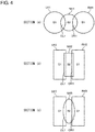
- Fig. 6 shows the rectangular discharge port NH2 drawn inside the circumscribed circle CSC. Referring to Figs. 1 , 4 , and 6 , an illustrative size setting method for the left inflow port LH2 and the right inflow port RH2 will be described.
- an area of the circumscribed circle CSC is indicated by a sign "S3".
- the area S1 of each of the left inflow port LH2 and the right inflow port RH2 may be set to be larger than the area S3 of the circumscribed circle CSC.
- a designer can set the form and the size of the left inflow port LH2 so that the left inflow port LH2 surrounds the entire area of overlapping between the left inflow port LH2 and the discharge port NH2 when the discharge port NH2 moves to the leftmost side.
- the design can set the form and the size of the right inflow port RH2 so that the right inflow port RH2 surrounds the entire area of overlapping between the right inflow port RH2 and the discharge port NH2 when the discharge port NH2 moves to the rightmost side.
- the hydraulic fluid discharged from the discharge port NH2 (that is, the discharge port 221 of Fig. 1 ) can flow into the left inflow port without being obstructed by the upper surface 310 (see Fig. 1 ) of the receiver 300 (see Fig. 1 ).
- the hydraulic fluid is efficiently supplied to the receiver 300.
- the hydraulic fluid discharged from the discharge port NH2 (that is, the discharge port 221 of Fig. 1 ) can flow into the right inflow port 312 (see Fig. 1 ) without being obstructed by the upper surface 310 (see Fig. 1 ) of the receiver 300 (see Fig. 1 ).
- the hydraulic fluid is efficiently supplied to the receiver 300.
- the receiver is provided with two inflow ports. While the hydraulic fluid flows into one of two inflow ports, the hydraulic fluid is discharged from the other of two inflow ports.
- the inflow port is excessively large, a discharge load of the hydraulic fluid from the other of two inflow ports is remarkably reduced. As a result, the actuator may not receive a sufficient pressure.
- other setting techniques for the size of the inflow port will be described.
- the areas S1 (see Fig. 4 ) of the left inflow port LH2 (see Fig. 4 ) and the right inflow port RH2 (see Fig. 4 ) may be set to be smaller than the area S3 (see Fig. 6 ) of the circumscribed circle CSC (see Fig. 6 ).
- the areas S1, S2, and S3 hold a relation shown in the following inequality.
- a designer can set the forms of the left inflow port LH2 and the right inflow port RH2 without largely increasing the sizes of the left inflow port LH2 and the right inflow port RH2 if the sizes and the forms of the left inflow port LH2 and the right inflow port RH2 are set under the relation represented by the above inequality.
- an actuator (not shown) can receive a sufficiently high pressure.
- the non-circular forms of the discharge port and the inflow port can be determined in consideration of various conditions including the area of overlapping between the discharge port and the inflow port, the easiness of the flow of the hydraulic fluid into the inflow port, and the pressure given to the actuator.
- a design who designs the servo-valve may determine the non-circular forms of, the discharge port and the inflow port in consideration of the pressure distribution of the hydraulic fluid discharged from the discharge port.
- the pressure distribution of the hydraulic fluid discharged from the discharge port approximates a Gaussian distribution having a peak at the center of the discharge port. When the peak of the pressure distribution overlaps the inflow port immediately after the nozzle starts to move, the servo-valve can achieve a high responsiveness.
- a non-circular form determining method considering the pressure distribution of the hydraulic fluid discharged from the discharge port will be described.
- Fig. 7 shows a coordinate plane in which shapes of the outline of the discharge port and the inflow port are drawn. Referring to Figs. 1 and 7 , a non-circular form determining method considering the pressure distribution of the hydraulic fluid discharged from the discharge port will be described.
- Fig. 7 shows a rectangular discharge port NH4, a trapezoidal left inflow port LH4, and a trapezoidal right inflow port RH4.
- the form of the discharge port NH4 can be applied to the discharge port 221 described with reference to Fig. 1 .
- the form of the left inflow port LH4 can be applied to the left inflow port 311 described with reference to Fig. 1 .
- the form of the right inflow port RH4 can be applied to the right inflow port 312 described with reference to Fig. 1 .
- the position of the discharge port NH4 shown in Fig. 7 corresponds to the nozzle 200 (see Fig. 1 ) at the initial position.
- the discharge port NH4 is drawn on the y axis.
- a center C1 of the discharge port NH4 is located on the y axis.
- the peak of the pressure distribution of the hydraulic fluid discharged from the discharge port NH4 is located at the center C1.
- the left inflow port LH4 is drawn at a second image limit of the coordinate shown in Fig. 7 .
- the right inflow port RH4 is drawn at a first image limit of the coordinate shown in Fig. 7 .
- the left inflow port LH4 is line-symmetrical to the right inflow port RH4 with respect to the y axis. That is, the form and the size of the left inflow port LH4 match those of the right inflow port RH4.
- the left inflow port LH4 includes a center C2.
- the right inflow port RH4 includes a center C3.
- the centers C1, C2, and C3 are aligned on a straight line parallel to the x axis.
- the extension direction of the x axis matches the movement direction of the nozzle 200.
- the discharge port NH4 partially overlaps the left inflow port LH4 and the right inflow port RH4. Each area of the left inflow port LH4 and the right inflow port RH4 is larger than the area of the discharge port NH4.
- the first inflow port is exemplified by one of the left inflow port LH4 and the right inflow port RH4.
- the second inflow port is exemplified by the other of the left inflow port LH4 and the right inflow port RH4.
- Fig. 7 shows a virtual circle VC1 and a center C4 of the virtual circle VC1.
- the virtual circle VC1 is drawn on the y axis.
- the center C4 is located on the y axis.
- the area of the virtual circle VC1 is the same as the area of the discharge port NH4.
- the small virtual circle is exemplified by the virtual circle VC1.
- Fig. 7 shows a virtual circle VC2 and a center C5 of the virtual circle VC2.
- the virtual circle VC2 is drawn at a third image limit.
- the x coordinate value of the center C5 of the virtual circle VC2 matches that of the center C2 of the left inflow port LH4.
- the area of the virtual circle VC2 is the same as the area of the left inflow port LH4.
- Fig. 7 shows a virtual circle VC3 and a center C6 of the virtual circle VC3.
- the virtual circle VC3 is drawn at a fourth image limit.
- the x coordinate value of the center C6 of the virtual circle VC3 matches that of the center C3 of the right inflow port RH4.
- the area of the virtual circle VC3 is the same as the area of the right inflow port RH4.
- the virtual circle VC3 is line-symmetrical to the virtual circle VC2 with respect to the y axis.
- the centers C4, C5, and C6 are aligned on a straight line parallel to the x axis.
- the large virtual circle is exemplified by one of the virtual circles VC2 and VC3.
- the outline of the left inflow port LH4 includes a straight line LSL which partially overlaps the discharge port NH4.
- the line LSL is parallel to the y axis.
- the x coordinate value of the line LSL is indicated by a sign "-x1".
- the coordinate value "-x1" indicates a distance between the outline of the left inflow port 311 and the extended line extended from the center of the discharge port 221 of the nozzle 200 at the initial position in the hydraulic fluid discharge direction.
- the outline of the right inflow port RH4 includes a straight line RSL which partially overlaps the discharge port NH4.
- the line RSL is parallel to the y axis.
- the x coordinate value of the line RSL is indicated by a sign "+x1".
- the coordinate value "+x1" indicates a distance between the outline of the right inflow port 312 and the extended line extended from the center of the discharge port 221 of the nozzle 200 at the initial position in the hydraulic fluid discharge direction.
- the virtual circle VC2 includes an arc LAC which overlaps the virtual circle VC1.
- the x coordinate value of the line which is tangential to the arc LAC and is parallel to the y axis is indicated by a sign "-x2".
- the coordinate value "-x2" indicates a distance between the outline of the circular left inflow port and the extended line passing through the center of the known circular discharge port.
- the virtual circle VC3 includes an arc RAC which overlaps the virtual circle VC1.
- the x coordinate value of the line which is tangential to the arc RAC and is parallel to the y axis is indicated by a sign "+x2".
- the coordinate value "+x2" indicates a distance between the outline of the circular right inflow port and the extended line passing through the center of the known circular discharge port.
- the designer may determine the forms of the discharge port NH4, the left inflow port LH4, and the right inflow port RH4. x 1 ⁇ x 2
- the known technique (the circular discharge port and the circular inflow port) requires a large stroke for the peak portion of the pressure distribution of the hydraulic fluid discharged from the discharge port to overlap the left or right inflow port (x2 > x1).
- the servo-valve 100 can exhibit a high response performance when the non-circular discharge port NH4 and/or the non-circular inflow port (the left inflow port LH4 and the right inflow port RH4) designed to hold the above-described expression is applied to the nozzle 200 and/or the receiver 300 described with reference to Fig. 1 .
- the servo-valve according to the above-described embodiment can be assembled to various fluidic devices driven by the hydraulic fluid.
- an illustrative fluidic device will be described.
- Fig. 8 is a schematic diagram showing a fluidic device 500 of the sixth embodiment. Referring to Figs. 1 and 8 , the fluidic device 500 will be described. The explanation of the first embodiment is incorporated in the description of the elements indicated by the same reference numerals as in the first embodiment.
- the fluidic device 500 includes a servo-valve 100A, an actuator 600, two pumps 510 and 520, and a tank 530.
- the servo-valve 100A includes a receiver 300.
- the explanation of the first embodiment is incorporated in the description of the receiver 300.
- the sizes and the forms of the left inflow port 311 and the right inflow port 312 formed in the upper surface 310 of the receiver 300 are determined based on the design principle described in the above-described embodiments.
- the servo-valve 100A includes a torque motor 400A.
- the torque motor 400A corresponds to the driving unit 400 described with reference to Fig. 1 .
- the explanation of the driving unit 400 is incorporated in the description of the torque motor 400A.
- the torque motor 400A includes a lower coil 411, an upper coil 412, a lower magnetic piece 421, an upper magnetic piece 422, and a magnetic rod 430.
- the upper coil 412 is disposed above the lower coil 411.
- the lower magnetic piece 421 may be formed in a substantially cylindrical form.
- the lower coil 411 is accommodated inside the lower magnetic piece 421.
- the upper magnetic piece 422 may be formed in a substantially cylindrical form.
- the upper coil 412 is disposed inside the upper magnetic piece 422.
- the lower edge of the upper magnetic piece 422 faces the upper edge of the lower magnetic piece 421.
- the magnetic rod 430 extends substantially horizontally.
- the left and right ends of the magnetic rod 430 are located in a gap between the upper edge of the lower magnetic piece 421 and the lower edge of the upper magnetic piece 422.
- a current is supplied to the lower coil 411 and the upper coil 412.
- the lower magnetic piece 421 and the upper magnetic piece 422 serve as magnets.
- the magnetic rod 430 rotates clockwise.
- the magnetic rod 430 rotates counterclockwise.
- the servo-valve 100A includes a nozzle portion 200A.
- the nozzle portion 200A corresponds to the nozzle 200 described with reference to Fig. 1 .
- the explanation of the nozzle 200 may be incorporated in the description of the nozzle portion 200A.
- the nozzle portion 200A includes a nozzle piece 240, a flexible tube 250, and a coupling shaft 260.
- the flexible tube 250 extends vertically to penetrate the torque motor 400A.
- the nozzle piece 240 is attached to the lower end of the flexible tube 250.
- the high-pressure hydraulic fluid is supplied to the flexible tube 250.
- the hydraulic fluid is guided by the flexible tube 250 to reach the nozzle piece 240.
- the nozzle piece 240 includes a lower surface 241 which faces the upper surface 310 of the receiver 300.
- the lower surface 241 is provided with a discharge port 242.
- the form and the size of the discharge port 242 are determined based on the design principle described in the above-described embodiments.
- the high-pressure hydraulic fluid which is supplied to the nozzle piece 240 is discharged from the discharge port 242. Subsequently, the hydraulic fluid flows into the receiver 300.
- the coupling shaft 260 is used so that the flexible tube 250 is coupled to an intermediate portion of the magnetic rod 430.
- the flexible tube 250 and the nozzle piece 240 move left and right in a reciprocating manner in response to the clockwise and counterclockwise rotations of the magnetic rod 430.
- the first position is exemplified by the position of the nozzle piece 240 moving left or right from the initial position (the position of the nozzle piece 240 in which the point of intersection between the upper surface 310 of the receiver 300 and the extended line extended from the center of the discharge port 242 in the hydraulic fluid discharge direction is located between the left inflow port 311 and the right inflow port 312).
- the second position is exemplified by the position of the nozzle piece 240 moving right or left from the initial position.
- the servo-valve 100A includes a spool valve 700.
- the spool valve 700 includes a casing 710, a spool 720, and a cantilever spring 730.
- the spool 720 is disposed inside the casing 710. As a result, a flow path through which the hydraulic fluid flows is formed inside the casing 710.
- the cantilever spring 730 is used so that the casing 710 and the spool 720 are coupled to each other.
- the cantilever spring 730 applies a force of keeping the spool 720 at the closed position to the spool 720.
- the spool valve 700 interrupts the hydraulic fluid supply path from the pumps 510 and 520 to the actuator 600.
- the spool 720 moves leftward or rightward from the closed position, the spool valve 700 opens the hydraulic fluid supply path from the pumps 510 and 520 to the actuator 600.
- the casing 710 is provided with seven ports 711 to 717.
- the port 711 is connected in fluid communication with the left outflow port 315 of the receiver 300.
- the port 712 is connected in fluid communication with the right outflow port 316 of the receiver 300.
- the pumps 510 and 520 are respectively attached to the ports 713 and 714.
- the ports 715 and 716 are connected in fluid communication with the actuator 600.
- the tank 530 is attached to the port 717.
- the spool 720 includes four partition walls 721, 722, 723, and 724 and a coupling shaft 725 used so that the partition walls 721, 722, 723, and 724 are coupled to one another.
- the coupling shaft 725 extends substantially horizontally.
- the partition wall 721 is formed at the left end of the coupling shaft 725.
- the partition wall 722 is formed at the right end of the coupling shaft 725.
- the partition wall 723 is located between the partition walls 721 and 722.
- the partition wall 724 is located between the partition walls 722 and 723.
- the partition walls 721, 722, 723, and 724 divide the inner space of the casing 710 into five chambers 741, 742, 743, 744, and 745.
- the chamber 741 moves to the leftmost side.
- the chamber 742 moves to the rightmost side.
- the chamber 743 is formed between the partition walls 721 and 723.
- the chamber 744 is formed between the partition walls 722 and 724.
- the chamber 745 is formed between the partition walls 723 and 724.
- the hydraulic fluid mainly flows from the discharge port 242 of the nozzle piece 240 to the left inflow port 311 of the receiver 300. Subsequently, the hydraulic fluid which flows into the left inflow port 311 flows into the chamber 741 through the left flow path 313 of the receiver 300, the left outflow port 315 of the receiver 300, and the port 711 of the spool valve 700. As a result, the inner pressure of the chamber 741 increases and the spool 720 moves rightward from the closed position.
- the hydraulic fluid which exists inside the chamber 742 is blown out from the right inflow port 312 through the port 712 of the spool valve 700, the right outflow port 316 of the receiver 300, and the right flow path 314 of the receiver 300.
- the hydraulic fluid ejected from the discharge port 242 of the nozzle piece 240 flows in substantially in the same quantity into the left inflow port 311 and the right inflow port 312 of the receiver 300.
- a force exerted on the left side of the spool 720 is larger than a force exerted on the right side of the spool 720 by a magnitude commensurate with the resilience of the cantilever spring 730.
- the spool 720 moves leftward and returns to the closed position.
- the hydraulic fluid mainly flows from the discharge port 242 of the nozzle piece 240 to the right inflow port 312 of the receiver 300. Subsequently, the hydraulic fluid which flows into the right inflow port 312 flows into the chamber 742 through the right flow path 314 of the receiver 300, the right outflow port 316 of the receiver 300, and the port 712 of the spool valve 700. As a result, the inner pressure of the chamber 742 increases and the spool 720 moves leftward from the closed position.
- the hydraulic fluid which exists inside the chamber 741 is blown out from the left inflow port 311 through the port 711 of the spool valve 700, the left outflow port 315 of the receiver 300, and the left flow path 313 of the receiver 300. Subsequently, when the nozzle piece 240 returns to the initial position, the hydraulic fluid which is ejected from the discharge port 242 of the nozzle piece 240 flows in substantially in the same quantity into the left inflow port 311 and the right inflow port 312 of the receiver 300.
- a force exerted on the right side of the spool 720 is larger than a force exerted on the left side of the spool 720 by a magnitude commensurate with the resilience of the cantilever spring 730.
- the spool 720 moves rightward and returns to the closed position.
- the partition wall 723 closes the port 715.
- the partition wall 724 closes the port 716.
- the pump 510 supplies the high-pressure hydraulic fluid to the chamber 743 through the port 713.
- the pump 520 supplies the high-pressure hydraulic fluid to the chamber 744 through the port 714.
- the hydraulic fluid supply path from the chamber 743 to the actuator 600 and the hydraulic fluid discharge path from the actuator 600 to the chamber 745 are opened.
- the hydraulic fluid supply path from the chamber 744 to the actuator 600 and the hydraulic fluid discharge path from the actuator 600 to the chamber 745 are opened.
- the amount of the hydraulic fluid flowing from the ports 715 and 716 to the actuator 600 is adjusted by the left and right movement of the nozzle piece 240.
- the first outflow port is exemplified by one of the ports 715 and 716.
- the second outflow port is exemplified by the other of the ports 715 and 716.
- the actuator 600 includes a casing 610 and a movable piece 620.
- the casing 610 is provided with two ports 611 and 612.
- the port 611 of the actuator 600 is connected in fluid communication with to the port 715 of the spool valve 700.
- the port 612 of the actuator 600 is connected in fluid communication with to the port 716 of the spool valve 700.
- the movable piece 620 includes a partition wall 621 and a rod 622.
- the partition wall 621 divides the inner space of the casing 610 into a left chamber 631 and a right chamber 632.
- the port 611 is coupled to the left chamber 631.
- the port 612 is coupled to the right chamber 632.
- the rod 622 extends right from the partition wall 621 and protrudes to the outside of the casing 610.
- the rod 622 is connected to other external devices (not show) disposed outside the casing 610.
- the hollow portion is exemplified by the inner space of the casing 610.
- the hydraulic fluid which is supplied from the pump 510 to the chamber 743 through the port 713 flows into the left chamber 631 through the ports 715 and 611. Since the inner pressure of the left chamber 631 increases, the movable piece 620 moves rightward. All this while, the right chamber 632 communicates with the chamber 745 through the ports 612 and 716. The hydraulic fluid which exists inside the right chamber 632 is extruded from the right chamber 632 by the movable piece 620 moving right so that the hydraulic fluid flows to the chamber 745. Subsequently, the hydraulic fluid which flows into the chamber 745 is stored in the tank 530.
- the hydraulic fluid which is supplied from the pump 520 to the chamber 744 through the port 714 flows into the right chamber 632 through the ports 716 and 612. Since the inner pressure of the right chamber 632 increases, the movable piece 620 moves leftward. All this while, the left chamber 631 communicates with the chamber 745 through the ports 611 and 715. The hydraulic fluid which exists inside the left chamber 631 is extruded from the left chamber 631 by the movable piece 620 moving left so that the hydraulic fluid flows into the chamber 745. Subsequently, the hydraulic fluid which flows into the chamber 745 is stored in the tank 530.
- the receiver 300 is drawn separately from the casing 710 of the spool valve 700.
- the receiver 300 may be integrated with the casing 710 of the spool valve 700.
- the cantilever spring 730 is coupled to the spool 720 and the casing 710.
- an elastic member coupling the spool 720 and the nozzle portion 200A to each other may be used.
- the actuator 600 is coupled to the spool valve 700.
- the actuator 600 may be directly coupled to the receiver 300.
- a designer can give various forms to the discharge port and the inflow port.
- various forms of the discharge port and the inflow port will be described.
- the form described in the seventh embodiment is illustrative.
- the designer can use other forms as the forms of the discharge port and the inflow port.
- the principle of the seventh embodiment is not limited in accordance with the forms below.
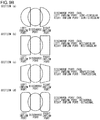
- Figs. 9A to 9E are schematic diagrams of various forms of the discharge port and the inflow port. Referring to Figs. 9A to 9E , various forms of the discharge port and the inflow port will be described.
- the sections (a) to (d) of Fig. 9A show the circular discharge port.
- the left inflow port and the right inflow port shown in the section (a) of Fig. 9A are semi-circular.
- the left inflow port and the right inflow port shown in the section (b) of Fig. 9A are rectangular.
- the left inflow port and the right inflow port shown in the section (c) of Fig. 9A are trapezoidal.
- the left inflow port and the right inflow port shown in the section (d) of Fig. 9A are octagonal.
- the sections (a) to (d) of Fig. 9B show the elliptical discharge port.
- the left inflow port and the right inflow port shown in the section (a) of Fig. 9B are semi-circular.
- the left inflow port and the right inflow port shown in the section (b) of Fig. 9B are rectangular.
- the left inflow port and the right inflow port shown in the section (c) of Fig. 9B are trapezoidal.
- the left inflow port and the right inflow port shown in the section (d) of Fig. 9B are octagonal.
- the sections (a) to (d) of Fig. 9C show the rectangular discharge port.
- the left inflow port and the right inflow port shown in the section (a) of Fig. 9C are semi-circular.
- the left inflow port and the right inflow port shown in the section (b) of Fig. 9C are rectangular.
- the left inflow port and the right inflow port shown in the section (c) of Fig. 9C are trapezoidal.
- the left inflow port and the right inflow port shown in the section (d) of Fig. 9C are octagonal.
- the sections (a) and (b) of Fig. 9D show the rectangular discharge port.
- the left inflow port and the right inflow port shown in the section (a) of Fig. 9D are elliptical.
- the left inflow port and the right inflow port shown in the section (b) of Fig. 9D are circular.
- the discharge port, the left inflow port, and the right inflow port shown in the section (c) of Fig. 9D are elliptical.
- an uneven form may be given to the discharge port, the left inflow port, and/or the right inflow port.
- At least one of the discharge port of the nozzle and the inflow port of the receiver is formed in a non-circular form such that an amount of change in the area of overlapping of the discharge port and the inflow port occurring when the nozzle is displaced from the initial position is larger compared to a case of a circular form in the same area.
- Fig. 10 is a diagram illustrating a relation of a change amount of the area of overlapping between the discharge port and the inflow port with respect to the nozzle displacement amount. The amount of displacement at the initial position of the nozzle is defined to be 0. A case in which the discharge port and the inflow port are formed in a circular form is indicated by a dashed line.
- a case in which at least one of the discharge port and the inflow port is formed in an elliptical form is indicated by the one-dotted chain line and a case in which at least one of the discharge port and the inflow port is formed in a rectangular form is indicated by a solid line.
- the fluid can flow into the inflow port in a short time. Accordingly, the response speed of the actuator is improved.
- the discharge port and the inflow port each having the non-circular form are formed by, for example, electric discharge machining.
- the designer can determine a method of forming the discharge port and the inflow port to be suitable for the forms of the discharge port and the inflow port.
- the principle of the embodiment is not limited to a specific forming technique for forming the non-circular discharge port and the non-circular inflow port and may use, for example, an AM technique (Additive Manufacturing) or the like.
- a servo-valve controls a fluid discharged from a discharge port of a nozzle by displacing the nozzle and drives an actuator.
- the servo-valve includes a receiver provided with an inflow port into which the fluid discharged from the discharge port flows. At least one of the discharge port and the inflow port is an opening formed in a non-circular form such that the amount of change in the area of overlapping of the discharge port and the inflow port occurring when the nozzle is displaced from the initial position is larger than when the discharge port and the inflow port are formed in circular forms of the same area.
- the change amount of the area of overlapping between the discharge port and the inflow port occurring when the nozzle is displaced from the initial position becomes larger than that of the case in which the opening is formed in the circular form in the same area. Accordingly, since the fluid can flow into the inflow port in a short time, the response speed of the actuator is improved.
- a width dimension of the opening in the nozzle displacement direction may be smaller than a diameter of the virtual circle in the same area as that of the opening.
- the change amount of the area of overlapping between the discharge port and the inflow port with respect to the nozzle displacement amount increases. Accordingly, since the fluid can flow into the inflow port in a short time, the response speed of the actuator can be improved.
- a curvature of the outline of the opening in the area of overlapping between the discharge port and the inflow port may be smaller than a curvature of a virtual circle in the same area as that of the opening.
- the curvature of the outline of the opening in the area of overlapping between the discharge port and the inflow port is smaller than the curvature of the virtual circle when the nozzle is located at the initial position, an increase rate of the area of overlapping between the discharge port and the inflow port increases when the nozzle is displaced by a short distance from the initial position. Since the servo-valve can allow the fluid to flow into the inflow port in a short time, the servo-valve can promptly drive the actuator.
- the opening may be formed such that a length dimension in a direction orthogonal to the nozzle displacement direction and the fluid discharge direction from the discharge port of the nozzle at the initial position is larger than a width dimension in the nozzle displacement direction.
- the opening since the opening has the length dimension larger than the width dimension in the direction orthogonal to the nozzle displacement direction and the fluid discharge direction from the discharge port of the nozzle at the initial position, the area of overlapping between the discharge port and the inflow port greatly increases when the nozzle is displaced by a short distance. Since the servo-valve can allow the fluid to flow into the inflow port in a short time, the servo-valve can promptly drive the actuator.
- an area of the inflow port may be larger than an area of the discharge port.
- the servo-valve can promptly drive the actuator by efficiently using the fluid.
- a length dimension of the inflow port may be larger than a length dimension of the discharge port.
- the servo-valve can promptly drive the actuator by efficiently using the fluid.
- the inflow port may be formed in a rectangular form having a pair of short sides extended in the nozzle displacement direction.
- the discharge port may be formed in a rectangular form having a pair of shorts sides extended in the nozzle displacement direction.
- a gap between the pair of short sides of the inflow port may be wider than a gap between the pair of short sides of the discharge port.
- the servo-valve can promptly drive the actuator by efficiently using the fluid.
- the discharge port may be formed in a non-circular form.
- the area of the inflow port may be smaller than the area of the circumscribed circle of the discharge port.
- the servo-valve can promptly drive the actuator by using the high fluid pressure.
- the discharge port may be formed in a non-circular form.
- the area of the inflow port may be larger than the area of the circumscribed circle of the inflow port.
- the servo-valve can promptly drive the actuator by efficiently using the fluid.
- the distance between an extended line extended from the center of the discharge port of the nozzle at the initial position in the direction of discharge and the outline of the inflow port in the area of overlapping of the discharge port and the inflow port may be smaller than the distance between the extended line to the arc of a virtual circle concentric with the discharge port and having the same area as the inflow port in the area of overlapping.
- the servo-valve can promptly drive the actuator by efficiently using the fluid.
- a driving unit that displaces the nozzle may be further provided and the inflow port may include a first inflow port and a second inflow port aligned in the nozzle displacement direction.
- the driving unit may move the nozzle in a reciprocating manner between a first position in which the amount of the fluid flowing into the first inflow port exceeds the amount of the fluid flowing into the second inflow port and a second position in which the amount of the fluid flowing into the second inflow port exceeds the amount of the fluid flowing into the first inflow port.
- the first inflow port and the second inflow port may have the same form and size.
- the fluid can efficiently flow into the first inflow port or the second inflow port in response to the reciprocating movement of the nozzle.
- the servo-valve can promptly drive the actuator by efficiently using the fluid.
- an extended line extended from the center of the discharge port of the nozzle in the fluid discharge direction may pass through a midpoint between the first inflow port and the second inflow port.
- the fluid discharged from the nozzle at the initial position can flow in substantially in the same quantity into the first inflow port and the second inflow port.
- the designer can design an actuator control using the servo-valve by using the initial position as a reference position.
- the extended line may intersect a straight line connecting the center of the first inflow port and the center of the second inflow port at a point P.
- the second inflow port may have a mirror image relation with respect to the first inflow port in a virtual plane enclosing a straight line passing through the point P and extended in a direction orthogonal to the nozzle displacement direction and the extended line.
- the second inflow port since the second inflow port has a mirror image relation with respect to the first inflow port in the virtual plane enclosing the line passing through the point P and extended in a second direction and the extended line, the fluid discharged from the nozzle at the initial position can flow in substantially in the same quantity into the first inflow port and the second inflow port.
- the designer can design a control using the servo-valve by using the initial position as a reference position.
- the servo-valve may further include a casing provided with a flow path through which the fluid flows.
- the casing may be provided with a first outflow port and a second outflow port.
- the driving unit may displace the nozzle between the first position and the second position to adjust the amount of the fluid flowing out of the first outflow port and the amount of the fluid flowing out of the second outflow port.
- the driving unit displaces the nozzle between the first position and the second position to adjust the amount of the fluid flowing out of the first outflow port and the amount of the fluid flowing out of the second outflow port
- the designer can operate a device connected to the servo-valve by changing a ratio of the outflow amounts from the first outflow port and the second outflow port.
- the opening may be selected from a group including an elliptical form, a polygonal form, and a form formed by an outline including a straight line and a curve.
- the opening is selected from a group including an elliptical form, a polygonal form, and a form formed by an outline including a straight line and a curve
- the designer who designs the servo-valve can determine the form of the opening in accordance with various conditions necessary for the servo-valve.
- a fluidic device includes the above-described servo-valve and a movable piece that is displaced by the fluid flowing through the servo-valve.
- the fluidic device including the servo-valve can be operated at a high response speed.
- the principle of the embodiments is very suitable for various devices obtaining a driving force from a fluid.
Landscapes
- Engineering & Computer Science (AREA)
- General Engineering & Computer Science (AREA)
- Mechanical Engineering (AREA)
- Physics & Mathematics (AREA)
- Fluid Mechanics (AREA)
- Multiple-Way Valves (AREA)
Abstract
Description
- The present invention relates to a servo-valve and a fluidic device having a high response performance.
- A servo-valve is used in airplanes or other industrial fields.
US Patent No. 2884907 discloses a technique of displacing a nozzle toward left and right sides of a rotation axis based on an electromagnetic principle to adjust the amount of hydraulic oil flowing into two inflow ports formed in a receiver. - A high response speed of the servo-valve results in a high accuracy of a control using the servo-valve. Thus, there have been various attempts for improving a mechanical mechanism and/or an electrical mechanism for driving the nozzle from the past. However, many of these improvements face various problems involving with a selection of a material, a mechanical strength, a complex control, and a manufacturing cost of the servo-valve.
- An object of the invention is to provide a simple technique of giving a high response speed to a servo-valve.
- A servo-valve according to an aspect of the invention controls a fluid discharged from a discharge port of a nozzle by displacing the nozzle and drives an actuator. The servo-valve includes a receiver provided with an inflow port into which the fluid discharged from the discharge port flows. At least one of the discharge port and the inflow port is an opening formed in a non-circular form such that the amount of change in the area of overlapping of the discharge port and the inflow port occurring when the nozzle is displaced from the initial position is larger than when the discharge port and the inflow port are formed in circular forms of the same area.
- According to the above-described configuration, the change amount of the area of overlapping of the discharge port and the inflow port occurring when the nozzle is displaced from the initial position is larger than that of a case in which the opening is formed in a circular form in the same area. Accordingly, since the fluid can flow into the inflow port in a short time, a response speed of the actuator is improved.
- A fluidic device according to another aspect of the invention includes the servo-valve and a movable piece which is displaced by the fluid in a hollow portion communicating with the first outflow port and the second outflow port.
- According to the above-described configuration, the fluidic device including the servo-valve can be operated at a high response speed.
-
-
Fig. 1 is a conceptual diagram showing a servo-valve of a first embodiment. -
Fig. 2 shows an illustrative form of a discharge port of the servo-valve shown inFig. 1 . -
Fig. 3 shows illustrative forms of a left inflow port and a right inflow port of the servo-valve shown inFig. 1 . -
Fig. 4 is a conceptual diagram showing an illustrative relation of the discharge port, the left inflow port, and the right inflow port of the servo-valve shown inFig. 1 (a second embodiment). -
Fig. 5 is a conceptual diagram showing a change in area of overlapping of the discharge port, the left inflow port, and the right inflow port of the servo-valve shown inFig. 1 . -
Fig. 6 shows a rectangular discharge port drawn inside a circumscribed circle (a third embodiment and a fourth embodiment). -
Fig. 7 is a coordinate plane in which shapes of the outline of a discharge port and an inflow port are drawn (a fifth embodiment). -
Fig. 8 is a schematic diagram showing a fluidic device of a sixth embodiment. -
Fig. 9A is a schematic diagram showing illustrative forms of a discharge port and an inflow port (a seventh embodiment). -
Fig. 9B is a schematic diagram showing the illustrative forms of the discharge port and the inflow port (a seventh embodiment). -
Fig. 9C is a schematic diagram showing the illustrative forms of the discharge port and the inflow port (a seventh embodiment). -
Fig. 9D is a schematic diagram showing the illustrative forms of the discharge port and the inflow port (a seventh embodiment). -
Fig. 9E is a schematic diagram showing the illustrative forms of the discharge port and the inflow port (a seventh embodiment). -
Fig. 10 is a diagram showing a change in area of overlapping of the discharge port and the inflow port with respect to a nozzle displacement amount. - The invention will now be described by reference to the preferred embodiments. This does not intend to limit the scope of the present invention, but to exemplify the invention.
- In a known servo-valve, a discharge port formed in a nozzle and an inflow port formed in a receiver both have a circular form. According to the survey of the inventors, when a form of a discharge port or an inflow port (hereinafter, also referred to as an "opening") is changed to a non-circular form, an area of overlapping between the discharge port and the inflow port abruptly increases compared to a case in which the opening is circular under a short nozzle stroke (a nozzle movement amount). As a result, since a necessary flow rate can be ensured at an early timing, a servo-valve and an actuator driven by the servo-valve are operated with high responsiveness. In the first embodiment, an illustrative servo-valve capable of realizing a high response performance using a non-circular opening will be described.
-
Fig. 1 is a conceptual diagram showing a servo-valve 100 of a first embodiment. The servo-valve 100 will be described with reference toFig. 1 . Terms like "upward", "downward", "leftward", "rightward", "clockwise", "counterclockwise", "vertical", and "horizontal" indicating directions are used merely for the purpose of making the explanation unambiguous. The principle of the embodiments is not by any means limited by these terms denoting the directions. - The servo-
valve 100 includes anozzle 200, areceiver 300, and adriving unit 400. Thedriving unit 400 turns (swings) (hereinafter, referred to as "oscillation movement" or "oscillation") a front end of thenozzle 200 in both directions (clockwise and counterclockwise) within a predetermined angle range about a rotation axis RAX defined at an upper portion of thenozzle 200. Thedriving unit 400 may be a general torque motor which gives a rotational force (a turning force) to thenozzle 200 using an electromagnetic force or other driving devices. The principle of the embodiment is not limited to a specific device used as thedriving unit 400. - The
nozzle 200 includes anupper surface 210 and alower surface 220. Thelower surface 220 faces thereceiver 300. Theupper surface 210 is located above thelower surface 220. Theupper surface 210 is provided with aninflow port 211. Theinflow port 211 is connected to a pump or other fluid supply sources supplying a hydraulic fluid. The hydraulic fluid (which will be referred to as, for example, hydraulic oil, but may be simply referred to as a "fluid" on the condition that the invention is not limited thereto) flows into thenozzle 200 through theinflow port 211. - The lower surface 220 (the front end surface) is provided with a
discharge port 221. Thenozzle 200 is provided with anozzle flow path 230 which extends downward from theinflow port 211 and is coupled to thedischarge port 221. Thenozzle flow path 230 becomes narrow toward thedischarge port 221. The hydraulic fluid which flows from theinflow port 211 into thenozzle 200 flows downward along thenozzle flow path 230 and is discharged from thedischarge port 221. Subsequently, the hydraulic fluid flows into thereceiver 300. - The
receiver 300 includes an upper surface (an opposite surface) 310 which faces thelower surface 220 of thenozzle 200. Theupper surface 310 is provided with aleft inflow port 311 and aright inflow port 312. Each of theleft inflow port 311 and theright inflow port 312 is formed to be larger than thedischarge port 221. Thereceiver 300 is provided with aleft flow path 313 and aright flow path 314. Theleft flow path 313 extends leftward and downward from theleft inflow port 311 and is terminated at theleft outflow port 315. Theright flow path 314 extends rightward and downward from theright inflow port 312 and is terminated at theright outflow port 316. Theleft outflow port 315 and theright outflow port 316 are formed in an outer surface of thereceiver 300 and are coupled to a spool valve (not shown) or an actuator (not shown). - A position of the
nozzle 200 when a center axis of the nozzle flow path 230 (an axis line connecting a center of theinflow port 211 and a center of the discharge port 221) matches a vertical axis will be referred to as an "initial position". When thenozzle 200 is located at the initial position, the hydraulic fluid discharged from thedischarge port 221 flow in substantially in the same quantity into theleft inflow port 311 and theright inflow port 312. In the embodiment, the first inflow port is exemplified by one of theleft inflow port 311 and theright inflow port 312. The second inflow port is exemplified by the other of theleft inflow port 311 and theright inflow port 312. - When the
nozzle 200 is oscillated from the initial position by the drivingunit 400, thedischarge port 221 moves leftward. At this time, the area of overlapping between thedischarge port 221 and theleft inflow port 311 increases and the area of overlapping between thedischarge port 221 and theright inflow port 312 decreases. As a result, the hydraulic fluid mainly flows into theleft inflow port 311. The hydraulic fluid which flows into theleft inflow port 311 flows out of theleft outflow port 315 to drive the spool valve or the actuator. All this while, the spool valve or the actuator extrudes the hydraulic fluid stored therein. The hydraulic fluid which is extruded by the spool valve or the actuator flows from theright outflow port 316 into theright flow path 314. Subsequently, the hydraulic fluid which flows into theright flow path 314 flows from theright inflow port 312 to a gap between thelower surface 220 of thenozzle 200 and theupper surface 310 of thereceiver 300. The hydraulic fluid which flows into the gap between thelower surface 220 of thenozzle 200 and theupper surface 310 of thereceiver 300 may be returned to a predetermined storage tank. - When the
nozzle 200 is oscillated counterclockwise from the initial position by the drivingunit 400, thedischarge port 221 moves rightward. At this time, the area of overlapping between thedischarge port 221 and theright inflow port 312 increases and the area of overlapping between thedischarge port 221 and theleft inflow port 311 decreases. As a result, the hydraulic fluid mainly flows into theright inflow port 312. The hydraulic fluid which flows into theright inflow port 312 flows out of theright outflow port 316 to drive the spool valve or the actuator. All this while, the spool valve or the actuator extrudes the hydraulic fluid stored therein. The hydraulic fluid which is extruded by the spool valve or the actuator flows from theleft outflow port 315 into theleft flow path 313. Subsequently, the hydraulic fluid which flows into theleft flow path 313 flows from theleft inflow port 311 to a gap between thelower surface 220 of thenozzle 200 and theupper surface 310 of thereceiver 300. The hydraulic fluid which flows into the gap between thelower surface 220 of thenozzle 200 and theupper surface 310 of thereceiver 300 may be returned to a predetermined storage tank. In the embodiment, the first direction is exemplified by one of left and right directions. - Various techniques used in the existing servo-valve may be applied when the hydraulic fluid is supplied, circulated, and stored. The principle of the embodiment is not limited to a specific process for the hydraulic fluid.
- The
discharge port 221 may be a non-circular opening. In this case, theleft inflow port 311 and theright inflow port 312 may be circular openings or non-circular openings. Thedischarge port 221 may be a circular opening. In this case, at least one of theleft inflow port 311 and theright inflow port 312 is a non-circular opening. -
Fig. 2 shows an illustrative form of thedischarge port 221. Referring toFigs. 1 and2 , a form of thedischarge port 221 will be described. - The section (a) of
Fig. 2 shows a discharge port DH1 of a known nozzle. The sections (b) to (d) ofFig. 2 respectively indicate discharge ports DH2, DH3, and DH4 which can be used as thedischarge port 221 described with reference toFig. 1 . - The discharge port DH1 is circular. The discharge port DH1 includes an area S0. In the section (a) of
Fig. 2 , the diameter of the discharge port DH1 is indicated by a sign "DM". In the embodiment, the diameter of the virtual circle is exemplified by the diameter DM. - The discharge port DH2 is rectangular. Like the discharge port DH1, the discharge port DH2 includes an area S0. In the section (b) of
Fig. 2 , the width of the discharge port DH2 is indicated by a sign "W1". The width W1 of the discharge port DH2 may be defined as a dimension of the discharge port DH2 in the movement direction of thedischarge port 221 or may be defined as a length of a short side of the discharge port DH2. As shown in the section (b) ofFig. 2 , the width W1 of the discharge port DH2 is smaller than the diameter DM of the discharge port DH1. - The discharge port DH3 is elliptical. Like the discharge port DH1, the discharge port DH3 includes an area S0. In the section (c) of
Fig. 2 , the width of the discharge port DH3 is indicated by a sign "W2". The width W2 of the discharge port DH3 may be defined as a dimension of the discharge port DH3 in the movement direction of thedischarge port 221 or may be defined as a length of a short axis of the discharge port DH3. As shown in the section (c) ofFig. 2 , the width W2 of the discharge port DH3 is smaller than the diameter DM of the discharge port DH1. - The discharge port DH4 has an elliptical form including two half arcs and two lines. Each of two lines extends in a direction orthogonal to the movement direction of the
discharge port 221. Two lines are arranged in series in the movement direction of thedischarge port 221. Two half arcs respectively connects ends of two lines. Like the discharge port DH1, the discharge port DH4 includes an area S0. In the section (d) ofFig. 2 , the width of the discharge port DH4 is indicated by a sign "W3". The width W3 of the discharge port DH4 may be defined as a dimension of the discharge port DH4 in the movement direction of thedischarge port 221 or may be defined as a gap between the lines of the discharge port DH3. As shown in the section (d) ofFig. 2 , the width W3 of the discharge port DH4 is smaller than the diameter DM of the discharge port DH1. - The sections (b) to (d) of
Fig. 2 respectively indicate dimensions "L1", "L2", and "L3" of discharge ports DH2, DH3, and DH4 in the longitudinal direction defined as a direction orthogonal to the movement direction of thedischarge port 221 and the discharge direction of the hydraulic fluid discharged from thedischarge port 221 at the initial position. As described above, the areas of the discharge ports DH2, DH3, and DH4 are the same as that of the discharge port DH1 and the widths W1, W2, and W3 of the discharge ports DH2, DH3, and DH4 are respectively smaller than the diameter DM of the discharge port DH1. Thus, the length dimensions L1, L2, and L3 of the discharge ports DH2, DH3, and DH4 are respectively larger than the diameter DM of the discharge port DH1. In the embodiment, the second direction is exemplified by the longitudinal direction. - Each of the discharge ports DH2, DH3, and DH4 has a symmetrical form with respect to an axis extended in the longitudinal direction. When the symmetrical form with respect to the axis extended in the longitudinal direction is selected as the form of the
discharge port 221, the hydraulic fluid flows in substantially in the same quantity into theleft inflow port 311 and theright inflow port 312 when thenozzle 200 is located at the initial position. -
Fig. 3 shows illustrative forms of theleft inflow port 311 and theright inflow port 312. Referring toFigs. 1 and3 , the forms of theleft inflow port 311 and theright inflow port 312 will be described. - The section (a) of
Fig. 3 indicates a left inflow port IL1 and a right inflow port IR1 of a known receiver. The sections (b) to (e) ofFig. 3 respectively indicate left inflow ports IL2, IL3, IL4, and IL5 used as theleft inflow port 311 and right inflow ports IR2, IR3, IR4, and IR5 used as theright inflow port 312 described with reference toFig. 1 . - Each of the left inflow port IL1 and the right inflow port IR1 is circular. Each of the left inflow port IL1 and the right inflow port IR1 includes an area S0. In the section (a) of
Fig. 3 , the diameter of each of the left inflow port IL1 and the right inflow port IR1 is indicated by a sign "DM". In the embodiment, the diameter of the virtual circle is exemplified by the diameter DM. - Each of the left inflow port IL2 and the right inflow port IR2 is rectangular. Like the left inflow port IL1, the left inflow port IL2 includes an area S0. Like the right inflow port IR1, the right inflow port IR2 includes an area S0. In the section (b) of
Fig. 3 , the width of each of the left inflow port IL2 and the right inflow port IR2 is indicated by a sign "W1". The widths W1 of the left inflow port IL2 and the right inflow port IR2 may be respectively defined as dimensions of the left inflow port IL2 and the right inflow port IR2 in the movement direction of thedischarge port 221 and may be defined as lengths of short sides of the left inflow port IL2 and the right inflow port IR2. As shown in the section (b) ofFig. 3 , the widths W1 of the left inflow port IL2 and the right inflow port IR2 are respectively smaller than the diameters DM of the left inflow port IL1 and the right inflow port IR1. - Each of the left inflow port IL3 and the right inflow port IR3 is elliptical. Like the left inflow port IL1, the left inflow port IL3 includes an area S0. Like the left inflow port IL1, the right inflow port IR3 includes an area S0. In the section (c) of
Fig. 3 , the widths of the left inflow port IL3 and the right inflow port IR3 are respectively indicated by a sign "W2". The widths W2 of the left inflow port IL3 and the right inflow port IR3 may be defined as the dimensions of the left inflow port IL3 and the right inflow port IR3 in the movement direction of thedischarge port 221 and may be defined as lengths of short axes of the left inflow port IL3 and the right inflow port IR3. As shown in the section (c) ofFig. 3 , the widths W2 of the left inflow port IL3 and the right inflow port IR3 are respectively smaller than the diameters DM of the left inflow port IL1 and the right inflow port IR1. - Each of the left inflow port IL4 and the right inflow port IR4 has an elliptical form including two half arcs and two lines. Each of two lines extends in a direction orthogonal to the movement direction of the
discharge port 221. Two lines are arranged in series in the movement direction of thedischarge port 221. Two half arcs respectively connect ends of two lines. Like the left inflow port IL1, the left inflow port IL4 includes an area S0. Like the right inflow port IR1, the right inflow port IR4 includes an area S0. In the section (d) ofFig. 3 , the widths of the left inflow port IL4 and the right inflow port IR4 are respectively indicated by a sign "W3". The widths W3 of the left inflow port IL4 and the right inflow port IR4 may be respectively defined as the dimensions of the left inflow port IL4 and the right inflow port IR4 in the movement direction of thedischarge port 221 and may be defined as gaps between the lines of the left inflow port IL4 and the right inflow port IR4. As shown in the section (d) ofFig. 3 , the widths W3 of the left inflow port IL4 and the right inflow port IR4 are smaller than the diameter DM of the discharge port DH1. - Each of the left inflow port IL5 and the right inflow port IR5 is triangular. Like the left inflow port IL1, the left inflow port IL5 includes an area S0. Like the right inflow port IR1, the right inflow port IR5 includes an area S0. In the section (e) of
Fig. 3 , the widths of the left inflow port IL5 and the right inflow port IR5 are indicated by a sign "W4". The widths W4 of the left inflow port IL5 and the right inflow port IR5 are respectively defined as the dimensions of the left inflow port IL5 and the right inflow port IR5 in the movement direction of thedischarge port 221. As shown the section (d) ofFig. 3 , the widths W4 of the left inflow port IL5 and the right inflow port IR5 are smaller than the diameters DM of the left inflow port IL1 and the right inflow port IR1. - In the section (b) of
Fig. 3 , the dimension of each of the left inflow port IL2 and the right inflow port IR2 in the longitudinal direction is indicated by "L1". In the section (c) ofFig. 3 , the dimension of each of the left inflow port IL3 and the right inflow port IR3 in the longitudinal direction is indicated by "L2". In the section (d) ofFig. 3 , the dimension of each of the left inflow port IL4 and the right inflow port IR4 in the longitudinal direction is indicated by "L3". In the section (e) ofFig. 3 , the dimension of each of the left inflow port IL5 and the right inflow port IR5 in the longitudinal direction is indicated by "L4". As described above, the areas of the left inflow ports IL2, IL3, IL4, and IL5 and the right inflow ports IR2, IR3, IR4, and IR5 are respectively the same as those of the left inflow port IL1 and the right inflow port IR1 and the widths W1, W2, W3, and W4 of the left inflow ports IL2, IL3, IL4, and IL5 and the right inflow ports IR2, IR3, IR4, and IR5 are smaller than the diameters DM of the left inflow port IL1 and the right inflow port IR1. Thus, the length dimensions L1, L2, L3, and L4 of the left inflow ports IL2, IL3, IL4, and IL5 and the right inflow ports IR2, IR3, IR4, and IR5 are larger than the diameters DM of the left inflow port IL1 and the right inflow port IR1. - The sections (b) to (e) of
Fig. 3 show a point P. The point P is located on an extended line which passes through the center of thedischarge port 221 of thenozzle 200 at the initial position and extends in the discharge direction of the hydraulic fluid discharged from thedischarge port 221 of thenozzle 200 at the initial position. The point P shown in the section (b) ofFig. 3 is located at the midpoint of the line connecting the center of the left inflow port IL2 and the center of the right inflow port IR2. The left inflow port IL2 has a mirror image relation with respect to the right inflow port IR2 in a virtual plane (not shown) enclosing the line passing through the point P and extended in the longitudinal direction and the extended line extended in the discharge direction of the hydraulic fluid discharged from thedischarge port 221 of thenozzle 200 located at the initial position. The point P shown in the section (c) ofFig. 3 is located at the midpoint of the line connecting the center of the left inflow port IL3 and the center of the right inflow port IR3. The left inflow port IL3 has a mirror image relation with respect to the right inflow port IR3 in the virtual plane (not shown) enclosing the line passing through the point P and extended in the longitudinal direction and the extended line extended in the discharge direction of the hydraulic fluid discharged from thedischarge port 221 of thenozzle 200 located at the initial position. The point P shown in the section (d) ofFig. 3 is located at the midpoint of the line connecting the center of the left inflow port IL4 and the center of the right inflow port IR4. The left inflow port IL4 has a mirror image relation with respect to the right inflow port IR4 in the virtual plane (not shown) enclosing the line passing through the point P and extended in the longitudinal direction and the extended line extended in the discharge direction of the hydraulic fluid discharged from thedischarge port 221 of thenozzle 200 located at the initial position. The point P shown in the section (e) ofFig. 3 is located at the midpoint of the line connecting the center of the left inflow port IL5 and the center of the right inflow port IR5. The left inflow port IL5 has a mirror image relation with respect to the right inflow port IR5 in the virtual plane (not shown) enclosing the line passing through the point P and extended in the longitudinal direction and the extended line extended in the discharge direction of the hydraulic fluid discharged from thedischarge port 221 of thenozzle 200 located at the initial position. - A servo-valve can have a high response performance when an area of overlapping between a discharge port and an inflow port changes greatly in response to the movement of a nozzle. In a second embodiment, an illustrative relation between the discharge port and the inflow port will be described.
-
Fig. 4 is a conceptual diagram showing an illustrative relation of thedischarge port 221, theleft inflow port 311, and theright inflow port 312. Referring toFigs. 1 to 4 , the form of thedischarge port 221 will be described. - The section (a) of
Fig. 4 shows a discharge port NH1, a left inflow port LH1, and a right inflow port RH1 of a known nozzle. The section (b) ofFig. 4 shows a discharge port NH2 which can be used as thedischarge port 221 described with reference toFig. 1 , a left inflow port LH2 which can be used as theleft inflow port 311 described with reference toFig. 1 , and a right inflow port RH2 which can be used as theright inflow port 312 described with reference toFig. 1 . The section (c) ofFig. 4 shows a discharge port NH3 which can be used as thedischarge port 221 described with reference toFig. 1 , a left inflow port LH3 which can be used as theleft inflow port 311 described with reference toFig. 1 , and a right inflow port RH3 which can be used as theright inflow port 312 described with reference toFig. 1 . - In the section (a) of
Fig. 4 , the areas of the left inflow port LH1 and the right inflow port RH1 are indicated by a sign "S1". In the section (a) ofFig. 4 , the area of the discharge port NH1 is indicated by a sign "S2". The area S1 is larger than the area S2. One of the area S1 and the area S2 corresponds to the area S0 described with reference toFigs. 2 and3 . - Like the left inflow port LH1, the left inflow port LH2 shown in the section (b) of
Fig. 4 includes an area S1. Like the right inflow port RH1, the right inflow port RH2 shown in the section (b) ofFig. 4 includes an area S1. Like the discharge port NH1, the discharge port NH2 shown in the section (b) ofFig. 4 includes an area S2. - Like the left inflow port LH1, the left inflow port LH3 shown in the section (c) of
Fig. 4 includes an area S1. Like the right inflow port RH1, the right inflow port RH3 shown in the section (c) ofFig. 4 includes an area S1. Like the discharge port NH1, the discharge port NH3 shown in the section (c) ofFig. 4 includes an area S2. - The discharge port NH1 shown in the section (a) of
Fig. 4 partially overlaps each of the left inflow port LH1 and the right inflow port RH1. In the section (a) ofFig. 4 , the area of overlapping between the discharge port NH1 and the left inflow port LH1 is indicated by a sign "OL1". In the section (a) ofFig. 4 , the area of overlapping between the discharge port NH1 and the right inflow port RH1 is indicated by a sign "OR1". When the discharge port NH1 moves leftward, the area of overlapping OL1 increases and the area of overlapping OR1 decreases. When the discharge port NH1 moves rightward, the area of overlapping OR1 increases and the area of overlapping OL1 decreases. When the area of overlapping OL1 is the same as the area of overlapping OR1, thenozzle 200 is located at the initial position. - The discharge port NH2 shown in the section (b) of
Fig. 4 partially overlaps each of the left inflow port LH2 and the right inflow port RH2. The relative positional relation between the left inflow port LH2 and the discharge port NH2 is set so that the area of overlapping between the discharge port NH2 and the left inflow port LH2 matches the area of overlapping OL1. The relative positional relation between the right inflow port RH2 and the discharge port NH2 is set so that the area of overlapping between the discharge port NH2 and the right inflow port RH2 matches the area of overlapping OR1. When the discharge port NH2 moves leftward, the area of overlapping OL1 increases and the area of overlapping OR1 decreases. When the discharge port NH2 moves rightward, the area of overlapping OR1 increases and the area of overlapping OL1 decreases. In the embodiment, the initial position may be exemplified by the position of thenozzle 200 which holds the positional relation shown in the section (b) ofFig. 4 . - The discharge port NH3 shown in the section (c) of
Fig. 4 partially overlaps the left inflow port LH3 and the right inflow port RH3. The relative positional relation between the left inflow port LH3 and the discharge port NH3 is set so that the area of overlapping between the discharge port NH3 and the left inflow port LH3 matches the area of overlapping OL1. The relative positional relation between the right inflow port RH3 and the discharge port NH3 is set so that the area of overlapping between the discharge port NH3 and the right inflow port RH3 matches the area of overlapping OR1. When the discharge port NH3 moves leftward, the area of overlapping OL1 increases and the area of overlapping OR1 decreases. When the discharge port NH3 moves rightward, the area of overlapping OR1 increases and the area of overlapping OL1 decreases. In the embodiment, the initial position may be exemplified as the position of thenozzle 200 which holds the positional relation shown in the section (c) ofFig. 4 . - Each of the left inflow port LH1 and the right inflow port RH1 shown in the section (a) of
Fig. 4 has a circular form including a radius R1. The discharge port NH1 shown in the section (a) ofFig. 4 has a circular form including a radius R2 smaller than the radius R1. Thus, the curvature of each outline of the left inflow port LH1 and the right inflow port RH1 inside the discharge port NH1 is "1/R1". The curvature of the outline of the discharge port NH1 inside the left inflow port LH1 or the right inflow port RH1 is "1/R2". In the embodiment, the virtual circle is exemplified by the circular form of each of the discharge port NH1, the left inflow port LH1, and the right inflow port RH1. - Each of the discharge port NH2, the left inflow port LH2, and the right inflow port RH2 shown in the section (b) of
Fig. 4 has a rectangular form in the longitudinal direction. The centers of the discharge port NH2, the left inflow port LH2, and the right inflow port RH2 are aligned in the movement direction of the discharge port NH2. A gap of a pair of short sides of each of the left inflow port LH2 and the right inflow port RH2 (a side extended in the movement direction of the discharge port NH2) is wider than a gap of a pair of short sides of the discharge port NH2 (a side extended in the movement direction of the discharge port NH2). Thus, a part of each of long sides of the left inflow port LH2 and the right inflow port RH2 is enclosed in the discharge port NH2. A pair of long sides of the discharge port NH2 (a side extended in a direction orthogonal to the movement direction of the discharge port NH2) is enclosed in the left inflow port LH2 and the right inflow port RH2 on the whole. Since the curvature of the long side is zero, the curvature is smaller than the curvatures "1/R1" and "1/R2" described in the section (a) ofFig. 4 . - The discharge port NH3 shown in the section (c) of
Fig. 4 is shaped in an ellipse elongated in the longitudinal direction and each of the left inflow port LH3 and the right inflow port RH3 has a rectangular form elongated in the longitudinal direction. The centers of the discharge port NH3, the left inflow port LH3, and the right inflow port RH3 are aligned in the movement direction of the discharge port NH3. As shown in the section (c) ofFig. 4 , a gap of a pair of short sides of each of the left inflow port LH3 and the right inflow port RH3 (a side extended in the movement direction of the discharge port NH3) is wider than the long axis dimension of the discharge port NH3. Thus, a part of long sides of the left inflow port LH3 and the right inflow port RH3 are enclosed in the discharge port NH3. Since the curvatures of the long sides are zero, the curvatures are smaller than the curvatures "1/R1" and "1/R2" described with reference to the section (a) ofFig. 4 . The outline having a small curvature (< 1/R2) of the discharge port NH3 is located inside each of the left inflow port LH3 and the right inflow port RH3 and the outline having a large curvature (> 1/R2) of the discharge port NH3 is located between the left inflow port LH3 and the right inflow port RH3. -
Fig. 5 is a conceptual diagram showing a change in area of overlapping. Referring toFigs. 1 ,4 , and5 , a change in area of overlapping will be described. - The section (a) of
Fig. 5 shows a change in area of overlapping between the discharge port NH1 and the left inflow port LH1 when the discharge port NH1 is displaced leftward. The discharge port NH1 indicated by a dotted line in the section (a) ofFig. 5 corresponds to the position of the discharge port NH1 described in the section (a) ofFig. 4 . The hatching area shown in the section (a) ofFig. 5 indicates an increment of the area of overlapping between the discharge port NH1 and the left inflow port LH1. An increment of the area of overlapping when the discharge port NH1 is displaced leftward is indicated by a sign "ΔOL1". - The section (b) of
Fig. 5 shows a change in area of overlapping between the discharge port NH2 and the left inflow port LH2 when the discharge port NH2 is displaced leftward. The discharge port NH2 indicated by a dotted line in the section (b) ofFig. 5 corresponds to the position of the discharge port NH2 described with respect to the section (b) ofFig. 4 . The leftward movement amount of the discharge port NH2 is the same as the leftward movement amount of the discharge port NH1. The hatching area shown in the section (b) ofFig. 5 indicates an increment of the area of overlapping between the discharge port NH2 and the left inflow port LH2. An increment of the area of overlapping when the discharge port NH2 is displaced leftward is indicated by a sign "ΔOL2". The increment ΔOL2 of the area of overlapping shown in the section (b) ofFig. 5 is larger than the increment ΔOL1 of the area of overlapping shown in the section (a) ofFig. 5 . This means that the inflow amount to theleft inflow port 311 and theright inflow port 312 greatly changes under a short stroke of thenozzle 200 when the form relation shown in the section (b) ofFig. 5 is used. That is, the servo-valve 100 can have a high response performance. - The section (c) of
Fig. 5 shows a change in area of overlapping between the discharge port NH3 and the left inflow port LH3 when the discharge port NH3 is displaced leftward. The discharge port NH3 indicated by a dotted line in the section (c) ofFig. 5 corresponds to the position of the discharge port NH3 described in the section (c) ofFig. 4 . The leftward movement amount of the discharge port NH3 is the same as the leftward movement amount of the discharge port NH1. The hatching area shown in the section (c) ofFig. 5 indicates an increment of the area of overlapping between the discharge port NH3 and the left inflow port LH3. An increment of the area of overlapping when the discharge port NH3 is displaced leftward is indicated by a sign "ΔOL3". The increment ΔOL3 of the area of overlapping shown in the section (c) ofFig. 5 is larger than the increment ΔOL1 of the area of overlapping shown in the section (a) ofFig. 5 . This means that the inflow amount to theleft inflow port 311 and theright inflow port 312 greatly changes under a short stroke of thenozzle 200 when the shale relation shown in the section (c) ofFig. 5 is used. That is, the servo-valve 100 can have a high response performance. - When the inflow port is sufficiently larger than the discharge port, the hydraulic fluid discharged from the discharge port can efficiently flow into the inflow port. In a third embodiment, an illustrative method for setting size of the inflow port will be described.
-
Fig. 6 shows the rectangular discharge port NH2 drawn inside the circumscribed circle CSC. Referring toFigs. 1 ,4 , and6 , an illustrative size setting method for the left inflow port LH2 and the right inflow port RH2 will be described. - In
Fig. 6 , an area of the circumscribed circle CSC is indicated by a sign "S3". The area S1 of each of the left inflow port LH2 and the right inflow port RH2 may be set to be larger than the area S3 of the circumscribed circle CSC. In this case, a designer can set the form and the size of the left inflow port LH2 so that the left inflow port LH2 surrounds the entire area of overlapping between the left inflow port LH2 and the discharge port NH2 when the discharge port NH2 moves to the leftmost side. Similarly, the design can set the form and the size of the right inflow port RH2 so that the right inflow port RH2 surrounds the entire area of overlapping between the right inflow port RH2 and the discharge port NH2 when the discharge port NH2 moves to the rightmost side. - If the left inflow port LH2 surrounds the entire area of overlapping between the left inflow port LH2 and the discharge port NH2 when the discharge port NH2 moves to the leftmost side, the hydraulic fluid discharged from the discharge port NH2 (that is, the
discharge port 221 ofFig. 1 ) can flow into the left inflow port without being obstructed by the upper surface 310 (seeFig. 1 ) of the receiver 300 (seeFig. 1 ). Thus, the hydraulic fluid is efficiently supplied to thereceiver 300. - If the right inflow port RH2 surrounds the entire area of overlapping between the right inflow port RH2 and the discharge port NH2 when the discharge port NH2 moves to the rightmost side, the hydraulic fluid discharged from the discharge port NH2 (that is, the
discharge port 221 ofFig. 1 ) can flow into the right inflow port 312 (seeFig. 1 ) without being obstructed by the upper surface 310 (seeFig. 1 ) of the receiver 300 (seeFig. 1 ). Thus, the hydraulic fluid is efficiently supplied to thereceiver 300. - As described in the first embodiment, the receiver is provided with two inflow ports. While the hydraulic fluid flows into one of two inflow ports, the hydraulic fluid is discharged from the other of two inflow ports. When the inflow port is excessively large, a discharge load of the hydraulic fluid from the other of two inflow ports is remarkably reduced. As a result, the actuator may not receive a sufficient pressure. In a fourth embodiment, other setting techniques for the size of the inflow port will be described.
- Differently from the third embodiment, the areas S1 (see
Fig. 4 ) of the left inflow port LH2 (seeFig. 4 ) and the right inflow port RH2 (seeFig. 4 ) may be set to be smaller than the area S3 (seeFig. 6 ) of the circumscribed circle CSC (seeFig. 6 ). In this case, the areas S1, S2, and S3 hold a relation shown in the following inequality.
- A designer can set the forms of the left inflow port LH2 and the right inflow port RH2 without largely increasing the sizes of the left inflow port LH2 and the right inflow port RH2 if the sizes and the forms of the left inflow port LH2 and the right inflow port RH2 are set under the relation represented by the above inequality. In this case, an actuator (not shown) can receive a sufficiently high pressure.
- As described in the embodiment, the non-circular forms of the discharge port and the inflow port can be determined in consideration of various conditions including the area of overlapping between the discharge port and the inflow port, the easiness of the flow of the hydraulic fluid into the inflow port, and the pressure given to the actuator. In addition, a design who designs the servo-valve may determine the non-circular forms of, the discharge port and the inflow port in consideration of the pressure distribution of the hydraulic fluid discharged from the discharge port. The pressure distribution of the hydraulic fluid discharged from the discharge port approximates a Gaussian distribution having a peak at the center of the discharge port. When the peak of the pressure distribution overlaps the inflow port immediately after the nozzle starts to move, the servo-valve can achieve a high responsiveness. In a fifth embodiment, a non-circular form determining method considering the pressure distribution of the hydraulic fluid discharged from the discharge port will be described.
-
Fig. 7 shows a coordinate plane in which shapes of the outline of the discharge port and the inflow port are drawn. Referring toFigs. 1 and7 , a non-circular form determining method considering the pressure distribution of the hydraulic fluid discharged from the discharge port will be described. -
Fig. 7 shows a rectangular discharge port NH4, a trapezoidal left inflow port LH4, and a trapezoidal right inflow port RH4. The form of the discharge port NH4 can be applied to thedischarge port 221 described with reference toFig. 1 . The form of the left inflow port LH4 can be applied to theleft inflow port 311 described with reference toFig. 1 . The form of the right inflow port RH4 can be applied to theright inflow port 312 described with reference toFig. 1 . - The position of the discharge port NH4 shown in
Fig. 7 corresponds to the nozzle 200 (seeFig. 1 ) at the initial position. The discharge port NH4 is drawn on the y axis. A center C1 of the discharge port NH4 is located on the y axis. The peak of the pressure distribution of the hydraulic fluid discharged from the discharge port NH4 is located at the center C1. - The left inflow port LH4 is drawn at a second image limit of the coordinate shown in
Fig. 7 . The right inflow port RH4 is drawn at a first image limit of the coordinate shown inFig. 7 . The left inflow port LH4 is line-symmetrical to the right inflow port RH4 with respect to the y axis. That is, the form and the size of the left inflow port LH4 match those of the right inflow port RH4. The left inflow port LH4 includes a center C2. The right inflow port RH4 includes a center C3. The centers C1, C2, and C3 are aligned on a straight line parallel to the x axis. The extension direction of the x axis matches the movement direction of thenozzle 200. The discharge port NH4 partially overlaps the left inflow port LH4 and the right inflow port RH4. Each area of the left inflow port LH4 and the right inflow port RH4 is larger than the area of the discharge port NH4. In the embodiment, the first inflow port is exemplified by one of the left inflow port LH4 and the right inflow port RH4. The second inflow port is exemplified by the other of the left inflow port LH4 and the right inflow port RH4. -
Fig. 7 shows a virtual circle VC1 and a center C4 of the virtual circle VC1. The virtual circle VC1 is drawn on the y axis. The center C4 is located on the y axis. The area of the virtual circle VC1 is the same as the area of the discharge port NH4. In the embodiment, the small virtual circle is exemplified by the virtual circle VC1. -
Fig. 7 shows a virtual circle VC2 and a center C5 of the virtual circle VC2. The virtual circle VC2 is drawn at a third image limit. The x coordinate value of the center C5 of the virtual circle VC2 matches that of the center C2 of the left inflow port LH4. The area of the virtual circle VC2 is the same as the area of the left inflow port LH4. -
Fig. 7 shows a virtual circle VC3 and a center C6 of the virtual circle VC3. The virtual circle VC3 is drawn at a fourth image limit. The x coordinate value of the center C6 of the virtual circle VC3 matches that of the center C3 of the right inflow port RH4. The area of the virtual circle VC3 is the same as the area of the right inflow port RH4. The virtual circle VC3 is line-symmetrical to the virtual circle VC2 with respect to the y axis. The centers C4, C5, and C6 are aligned on a straight line parallel to the x axis. In the embodiment, the large virtual circle is exemplified by one of the virtual circles VC2 and VC3. - The outline of the left inflow port LH4 includes a straight line LSL which partially overlaps the discharge port NH4. The line LSL is parallel to the y axis. In
Fig. 7 , the x coordinate value of the line LSL is indicated by a sign "-x1". The coordinate value "-x1" indicates a distance between the outline of theleft inflow port 311 and the extended line extended from the center of thedischarge port 221 of thenozzle 200 at the initial position in the hydraulic fluid discharge direction. - The outline of the right inflow port RH4 includes a straight line RSL which partially overlaps the discharge port NH4. The line RSL is parallel to the y axis. In
Fig. 7 , the x coordinate value of the line RSL is indicated by a sign "+x1". The coordinate value "+x1" indicates a distance between the outline of theright inflow port 312 and the extended line extended from the center of thedischarge port 221 of thenozzle 200 at the initial position in the hydraulic fluid discharge direction. - The virtual circle VC2 includes an arc LAC which overlaps the virtual circle VC1. In
Fig. 7 , the x coordinate value of the line which is tangential to the arc LAC and is parallel to the y axis is indicated by a sign "-x2". The coordinate value "-x2" indicates a distance between the outline of the circular left inflow port and the extended line passing through the center of the known circular discharge port. - The virtual circle VC3 includes an arc RAC which overlaps the virtual circle VC1. In
Fig. 7 , the x coordinate value of the line which is tangential to the arc RAC and is parallel to the y axis is indicated by a sign "+x2". The coordinate value "+x2" indicates a distance between the outline of the circular right inflow port and the extended line passing through the center of the known circular discharge port. - In order to hold a relation expressed by the following inequality, the designer may determine the forms of the discharge port NH4, the left inflow port LH4, and the right inflow port RH4.

- When the relation expressed by the above inequality is held, the peak portion of the pressure distribution of the hydraulic fluid overlaps the left inflow port LH4 as soon as the discharge port NH4 moves leftward. As a result, a large amount of the hydraulic fluid can flow into the left inflow port LH4.
- When the relation expressed by the above inequality is held, the peak portion of the pressure distribution of the hydraulic fluid overlaps the right inflow port RH4 as soon as the discharge port NH4 moves rightward. As a result, a large amount of the hydraulic fluid can flow into the right inflow port RH4.
- Meanwhile, the known technique (the circular discharge port and the circular inflow port) requires a large stroke for the peak portion of the pressure distribution of the hydraulic fluid discharged from the discharge port to overlap the left or right inflow port (x2 > x1). Thus, the servo-
valve 100 can exhibit a high response performance when the non-circular discharge port NH4 and/or the non-circular inflow port (the left inflow port LH4 and the right inflow port RH4) designed to hold the above-described expression is applied to thenozzle 200 and/or thereceiver 300 described with reference toFig. 1 . - The servo-valve according to the above-described embodiment can be assembled to various fluidic devices driven by the hydraulic fluid. In a sixth embodiment, an illustrative fluidic device will be described.
-
Fig. 8 is a schematic diagram showing afluidic device 500 of the sixth embodiment. Referring toFigs. 1 and8 , thefluidic device 500 will be described. The explanation of the first embodiment is incorporated in the description of the elements indicated by the same reference numerals as in the first embodiment. - The
fluidic device 500 includes a servo-valve 100A, anactuator 600, twopumps tank 530. Like the first embodiment, the servo-valve 100A includes areceiver 300. The explanation of the first embodiment is incorporated in the description of thereceiver 300. The sizes and the forms of theleft inflow port 311 and theright inflow port 312 formed in theupper surface 310 of thereceiver 300 are determined based on the design principle described in the above-described embodiments. - The servo-
valve 100A includes atorque motor 400A. Thetorque motor 400A corresponds to thedriving unit 400 described with reference toFig. 1 . The explanation of thedriving unit 400 is incorporated in the description of thetorque motor 400A. - The
torque motor 400A includes alower coil 411, anupper coil 412, a lowermagnetic piece 421, an uppermagnetic piece 422, and amagnetic rod 430. Theupper coil 412 is disposed above thelower coil 411. The lowermagnetic piece 421 may be formed in a substantially cylindrical form. Thelower coil 411 is accommodated inside the lowermagnetic piece 421. Like the lowermagnetic piece 421, the uppermagnetic piece 422 may be formed in a substantially cylindrical form. Theupper coil 412 is disposed inside the uppermagnetic piece 422. The lower edge of the uppermagnetic piece 422 faces the upper edge of the lowermagnetic piece 421. Themagnetic rod 430 extends substantially horizontally. The left and right ends of themagnetic rod 430 are located in a gap between the upper edge of the lowermagnetic piece 421 and the lower edge of the uppermagnetic piece 422. - A current is supplied to the
lower coil 411 and theupper coil 412. As a result, the lowermagnetic piece 421 and the uppermagnetic piece 422 serve as magnets. When a current is supplied to thelower coil 411 and theupper coil 412 so that the right end of themagnetic rod 430 is pulled to the lowermagnetic piece 421 and the left end of themagnetic rod 430 is pulled to the uppermagnetic piece 422, themagnetic rod 430 rotates clockwise. When a current is supplied to thelower coil 411 and theupper coil 412 so that the left end of themagnetic rod 430 is pulled to the lowermagnetic piece 421 and the right end of themagnetic rod 430 is pulled to the uppermagnetic piece 422, themagnetic rod 430 rotates counterclockwise. - The servo-
valve 100A includes anozzle portion 200A. Thenozzle portion 200A corresponds to thenozzle 200 described with reference toFig. 1 . The explanation of thenozzle 200 may be incorporated in the description of thenozzle portion 200A. - The
nozzle portion 200A includes anozzle piece 240, aflexible tube 250, and acoupling shaft 260. Theflexible tube 250 extends vertically to penetrate thetorque motor 400A. Thenozzle piece 240 is attached to the lower end of theflexible tube 250. The high-pressure hydraulic fluid is supplied to theflexible tube 250. The hydraulic fluid is guided by theflexible tube 250 to reach thenozzle piece 240. - The
nozzle piece 240 includes alower surface 241 which faces theupper surface 310 of thereceiver 300. Thelower surface 241 is provided with adischarge port 242. The form and the size of thedischarge port 242 are determined based on the design principle described in the above-described embodiments. The high-pressure hydraulic fluid which is supplied to thenozzle piece 240 is discharged from thedischarge port 242. Subsequently, the hydraulic fluid flows into thereceiver 300. - The
coupling shaft 260 is used so that theflexible tube 250 is coupled to an intermediate portion of themagnetic rod 430. Theflexible tube 250 and thenozzle piece 240 move left and right in a reciprocating manner in response to the clockwise and counterclockwise rotations of themagnetic rod 430. In the embodiment, the first position is exemplified by the position of thenozzle piece 240 moving left or right from the initial position (the position of thenozzle piece 240 in which the point of intersection between theupper surface 310 of thereceiver 300 and the extended line extended from the center of thedischarge port 242 in the hydraulic fluid discharge direction is located between theleft inflow port 311 and the right inflow port 312). The second position is exemplified by the position of thenozzle piece 240 moving right or left from the initial position. - When the
magnetic rod 430 rotates about thecoupling shaft 260 clockwise, thenozzle piece 240 moves leftward. As a result, the area of overlapping between thedischarge port 242 and theleft inflow port 311 increases and the area of overlapping between thedischarge port 242 and theright inflow port 312 decreases. In this case, the amount of the hydraulic fluid flowing into theleft flow path 313 formed inside thereceiver 300 exceeds the flow rate of the hydraulic fluid flowing into theright flow path 314. - When the
magnetic rod 430 rotates about thecoupling shaft 260 counterclockwise, thenozzle piece 240 moves rightward. As a result, the area of overlapping between thedischarge port 242 and theright inflow port 312 increases and the area of overlapping between thedischarge port 242 and theleft inflow port 311 decreases. In this case, the amount of the hydraulic fluid flowing into theright flow path 314 formed inside thereceiver 300 exceeds the flow rate of the hydraulic fluid flowing into theleft flow path 313. - The servo-
valve 100A includes aspool valve 700. Thespool valve 700 includes acasing 710, aspool 720, and acantilever spring 730. Thespool 720 is disposed inside thecasing 710. As a result, a flow path through which the hydraulic fluid flows is formed inside thecasing 710. Thecantilever spring 730 is used so that thecasing 710 and thespool 720 are coupled to each other. Thecantilever spring 730 applies a force of keeping thespool 720 at the closed position to thespool 720. When thespool 720 is located at the closed position, thespool valve 700 interrupts the hydraulic fluid supply path from thepumps actuator 600. When thespool 720 moves leftward or rightward from the closed position, thespool valve 700 opens the hydraulic fluid supply path from thepumps actuator 600. - The
casing 710 is provided with sevenports 711 to 717. Theport 711 is connected in fluid communication with theleft outflow port 315 of thereceiver 300. Theport 712 is connected in fluid communication with theright outflow port 316 of thereceiver 300. Thepumps ports ports actuator 600. Thetank 530 is attached to theport 717. - The
spool 720 includes fourpartition walls coupling shaft 725 used so that thepartition walls coupling shaft 725 extends substantially horizontally. Thepartition wall 721 is formed at the left end of thecoupling shaft 725. Thepartition wall 722 is formed at the right end of thecoupling shaft 725. Thepartition wall 723 is located between thepartition walls partition wall 724 is located between thepartition walls - The
partition walls casing 710 into fivechambers chamber 741 moves to the leftmost side. Thechamber 742 moves to the rightmost side. Thechamber 743 is formed between thepartition walls chamber 744 is formed between thepartition walls chamber 745 is formed between thepartition walls - When the
nozzle piece 240 moves leftward, the hydraulic fluid mainly flows from thedischarge port 242 of thenozzle piece 240 to theleft inflow port 311 of thereceiver 300. Subsequently, the hydraulic fluid which flows into theleft inflow port 311 flows into thechamber 741 through theleft flow path 313 of thereceiver 300, theleft outflow port 315 of thereceiver 300, and theport 711 of thespool valve 700. As a result, the inner pressure of thechamber 741 increases and thespool 720 moves rightward from the closed position. All this while, the hydraulic fluid which exists inside thechamber 742 is blown out from theright inflow port 312 through theport 712 of thespool valve 700, theright outflow port 316 of thereceiver 300, and theright flow path 314 of thereceiver 300. Subsequently, when thenozzle piece 240 returns to the initial position, the hydraulic fluid ejected from thedischarge port 242 of thenozzle piece 240 flows in substantially in the same quantity into theleft inflow port 311 and theright inflow port 312 of thereceiver 300. All this while, a force exerted on the left side of thespool 720 is larger than a force exerted on the right side of thespool 720 by a magnitude commensurate with the resilience of thecantilever spring 730. Thus, thespool 720 moves leftward and returns to the closed position. - When the
nozzle piece 240 moves rightward, the hydraulic fluid mainly flows from thedischarge port 242 of thenozzle piece 240 to theright inflow port 312 of thereceiver 300. Subsequently, the hydraulic fluid which flows into theright inflow port 312 flows into thechamber 742 through theright flow path 314 of thereceiver 300, theright outflow port 316 of thereceiver 300, and theport 712 of thespool valve 700. As a result, the inner pressure of thechamber 742 increases and thespool 720 moves leftward from the closed position. All this while, the hydraulic fluid which exists inside thechamber 741 is blown out from theleft inflow port 311 through theport 711 of thespool valve 700, theleft outflow port 315 of thereceiver 300, and theleft flow path 313 of thereceiver 300. Subsequently, when thenozzle piece 240 returns to the initial position, the hydraulic fluid which is ejected from thedischarge port 242 of thenozzle piece 240 flows in substantially in the same quantity into theleft inflow port 311 and theright inflow port 312 of thereceiver 300. All this while, a force exerted on the right side of thespool 720 is larger than a force exerted on the left side of thespool 720 by a magnitude commensurate with the resilience of thecantilever spring 730. Thus, thespool 720 moves rightward and returns to the closed position. - When the
spool 720 is located at the closed position, thepartition wall 723 closes theport 715. At this time, thepartition wall 724 closes theport 716. Thepump 510 supplies the high-pressure hydraulic fluid to thechamber 743 through theport 713. Thepump 520 supplies the high-pressure hydraulic fluid to thechamber 744 through theport 714. When thespool 720 moves rightward from the closed position, the hydraulic fluid supply path from thechamber 743 to theactuator 600 and the hydraulic fluid discharge path from theactuator 600 to thechamber 745 are opened. When thespool 720 moves leftward from the closed position, the hydraulic fluid supply path from thechamber 744 to theactuator 600 and the hydraulic fluid discharge path from theactuator 600 to thechamber 745 are opened. Thus, the amount of the hydraulic fluid flowing from theports actuator 600 is adjusted by the left and right movement of thenozzle piece 240. In the embodiment, the first outflow port is exemplified by one of theports ports - The
actuator 600 includes acasing 610 and amovable piece 620. Thecasing 610 is provided with twoports port 611 of theactuator 600 is connected in fluid communication with to theport 715 of thespool valve 700. Theport 612 of theactuator 600 is connected in fluid communication with to theport 716 of thespool valve 700. - The
movable piece 620 includes apartition wall 621 and arod 622. Thepartition wall 621 divides the inner space of thecasing 610 into aleft chamber 631 and aright chamber 632. Theport 611 is coupled to theleft chamber 631. Theport 612 is coupled to theright chamber 632. Therod 622 extends right from thepartition wall 621 and protrudes to the outside of thecasing 610. Therod 622 is connected to other external devices (not show) disposed outside thecasing 610. In the embodiment, the hollow portion is exemplified by the inner space of thecasing 610. - When the
spool 720 moves rightward from the closed position, the hydraulic fluid which is supplied from thepump 510 to thechamber 743 through theport 713 flows into theleft chamber 631 through theports left chamber 631 increases, themovable piece 620 moves rightward. All this while, theright chamber 632 communicates with thechamber 745 through theports right chamber 632 is extruded from theright chamber 632 by themovable piece 620 moving right so that the hydraulic fluid flows to thechamber 745. Subsequently, the hydraulic fluid which flows into thechamber 745 is stored in thetank 530. - When the
spool 720 moves leftward from the closed position, the hydraulic fluid which is supplied from thepump 520 to thechamber 744 through theport 714 flows into theright chamber 632 through theports right chamber 632 increases, themovable piece 620 moves leftward. All this while, theleft chamber 631 communicates with thechamber 745 through theports left chamber 631 is extruded from theleft chamber 631 by themovable piece 620 moving left so that the hydraulic fluid flows into thechamber 745. Subsequently, the hydraulic fluid which flows into thechamber 745 is stored in thetank 530. - In
Fig. 8 , thereceiver 300 is drawn separately from thecasing 710 of thespool valve 700. However, thereceiver 300 may be integrated with thecasing 710 of thespool valve 700. - In the embodiment, the
cantilever spring 730 is coupled to thespool 720 and thecasing 710. Instead of thecantilever spring 730, an elastic member coupling thespool 720 and thenozzle portion 200A to each other may be used. - In the embodiment, the
actuator 600 is coupled to thespool valve 700. However, theactuator 600 may be directly coupled to thereceiver 300. - Based on the design principle described in the above-described embodiments, a designer can give various forms to the discharge port and the inflow port. In a seventh embodiment, various forms of the discharge port and the inflow port will be described. The form described in the seventh embodiment is illustrative. The designer can use other forms as the forms of the discharge port and the inflow port. Thus, the principle of the seventh embodiment is not limited in accordance with the forms below.
-
Figs. 9A to 9E are schematic diagrams of various forms of the discharge port and the inflow port. Referring toFigs. 9A to 9E , various forms of the discharge port and the inflow port will be described. - The sections (a) to (d) of
Fig. 9A show the circular discharge port. The left inflow port and the right inflow port shown in the section (a) ofFig. 9A are semi-circular. The left inflow port and the right inflow port shown in the section (b) ofFig. 9A are rectangular. The left inflow port and the right inflow port shown in the section (c) ofFig. 9A are trapezoidal. The left inflow port and the right inflow port shown in the section (d) ofFig. 9A are octagonal. - The sections (a) to (d) of
Fig. 9B show the elliptical discharge port. The left inflow port and the right inflow port shown in the section (a) ofFig. 9B are semi-circular. The left inflow port and the right inflow port shown in the section (b) ofFig. 9B are rectangular. The left inflow port and the right inflow port shown in the section (c) ofFig. 9B are trapezoidal. The left inflow port and the right inflow port shown in the section (d) ofFig. 9B are octagonal. - The sections (a) to (d) of
Fig. 9C show the rectangular discharge port. The left inflow port and the right inflow port shown in the section (a) ofFig. 9C are semi-circular. The left inflow port and the right inflow port shown in the section (b) ofFig. 9C are rectangular. The left inflow port and the right inflow port shown in the section (c) ofFig. 9C are trapezoidal. The left inflow port and the right inflow port shown in the section (d) ofFig. 9C are octagonal. - The sections (a) and (b) of
Fig. 9D show the rectangular discharge port. The left inflow port and the right inflow port shown in the section (a) ofFig. 9D are elliptical. The left inflow port and the right inflow port shown in the section (b) ofFig. 9D are circular. The discharge port, the left inflow port, and the right inflow port shown in the section (c) ofFig. 9D are elliptical. As shown inFig. 9E , an uneven form may be given to the discharge port, the left inflow port, and/or the right inflow port. - As above, the embodiments of the invention have been described. According to the embodiment, at least one of the discharge port of the nozzle and the inflow port of the receiver is formed in a non-circular form such that an amount of change in the area of overlapping of the discharge port and the inflow port occurring when the nozzle is displaced from the initial position is larger compared to a case of a circular form in the same area.
Fig. 10 is a diagram illustrating a relation of a change amount of the area of overlapping between the discharge port and the inflow port with respect to the nozzle displacement amount. The amount of displacement at the initial position of the nozzle is defined to be 0. A case in which the discharge port and the inflow port are formed in a circular form is indicated by a dashed line. Further, a case in which at least one of the discharge port and the inflow port is formed in an elliptical form is indicated by the one-dotted chain line and a case in which at least one of the discharge port and the inflow port is formed in a rectangular form is indicated by a solid line. According to the embodiment, since a change amount of the area of overlapping with respect to the nozzle displacement amount increases compared to a case in which the discharge port and the inflow port are formed in a circular form, the fluid can flow into the inflow port in a short time. Accordingly, the response speed of the actuator is improved. - The design principle described in various embodiments can be applied to various servo-valves and fluidic devices. A part of various features described in one of various embodiments may be applied to the servo-valve and the fluidic device according to another embodiment.
- The discharge port and the inflow port each having the non-circular form are formed by, for example, electric discharge machining. However, the designer can determine a method of forming the discharge port and the inflow port to be suitable for the forms of the discharge port and the inflow port. Thus, the principle of the embodiment is not limited to a specific forming technique for forming the non-circular discharge port and the non-circular inflow port and may use, for example, an AM technique (Additive Manufacturing) or the like.
- An aspect of the invention is as below. A servo-valve according to an aspect of the invention controls a fluid discharged from a discharge port of a nozzle by displacing the nozzle and drives an actuator. The servo-valve includes a receiver provided with an inflow port into which the fluid discharged from the discharge port flows. At least one of the discharge port and the inflow port is an opening formed in a non-circular form such that the amount of change in the area of overlapping of the discharge port and the inflow port occurring when the nozzle is displaced from the initial position is larger than when the discharge port and the inflow port are formed in circular forms of the same area.
- According to the above-described configuration, the change amount of the area of overlapping between the discharge port and the inflow port occurring when the nozzle is displaced from the initial position becomes larger than that of the case in which the opening is formed in the circular form in the same area. Accordingly, since the fluid can flow into the inflow port in a short time, the response speed of the actuator is improved.
- In the above-described configuration, a width dimension of the opening in the nozzle displacement direction may be smaller than a diameter of the virtual circle in the same area as that of the opening.
- According to the above-described configuration, the change amount of the area of overlapping between the discharge port and the inflow port with respect to the nozzle displacement amount increases. Accordingly, since the fluid can flow into the inflow port in a short time, the response speed of the actuator can be improved.
- In the above-described configuration, when the nozzle is located at the initial position, a curvature of the outline of the opening in the area of overlapping between the discharge port and the inflow port may be smaller than a curvature of a virtual circle in the same area as that of the opening.
- Since the curvature of the outline of the opening in the area of overlapping between the discharge port and the inflow port is smaller than the curvature of the virtual circle when the nozzle is located at the initial position, an increase rate of the area of overlapping between the discharge port and the inflow port increases when the nozzle is displaced by a short distance from the initial position. Since the servo-valve can allow the fluid to flow into the inflow port in a short time, the servo-valve can promptly drive the actuator.
- In the above-described configuration, the opening may be formed such that a length dimension in a direction orthogonal to the nozzle displacement direction and the fluid discharge direction from the discharge port of the nozzle at the initial position is larger than a width dimension in the nozzle displacement direction.
- According to the above-described configuration, since the opening has the length dimension larger than the width dimension in the direction orthogonal to the nozzle displacement direction and the fluid discharge direction from the discharge port of the nozzle at the initial position, the area of overlapping between the discharge port and the inflow port greatly increases when the nozzle is displaced by a short distance. Since the servo-valve can allow the fluid to flow into the inflow port in a short time, the servo-valve can promptly drive the actuator.
- In the above-described configuration, an area of the inflow port may be larger than an area of the discharge port.
- According to the above-described configuration, since the area of the inflow port is larger than the area of the discharge port, the fluid discharged from the discharge port can easily flow into the inflow port. Thus, the servo-valve can promptly drive the actuator by efficiently using the fluid.
- In the above-described configuration, a length dimension of the inflow port may be larger than a length dimension of the discharge port.
- According to the above-described configuration, since the length dimension of the inflow port is larger than that of the discharge port, the fluid discharged from the discharge port can easily flow into the inflow port. Thus, the servo-valve can promptly drive the actuator by efficiently using the fluid.
- In the above-described configuration, the inflow port may be formed in a rectangular form having a pair of short sides extended in the nozzle displacement direction. The discharge port may be formed in a rectangular form having a pair of shorts sides extended in the nozzle displacement direction. A gap between the pair of short sides of the inflow port may be wider than a gap between the pair of short sides of the discharge port.
- According to the above-described configuration, since the gap between the pair of short sides of the inflow port is wider than the gap between the pair of short sides of the discharge port, the fluid discharged from the discharge port can easily flow into the inflow port. Thus, the servo-valve can promptly drive the actuator by efficiently using the fluid.
- In the above-described configuration, the discharge port may be formed in a non-circular form. The area of the inflow port may be smaller than the area of the circumscribed circle of the discharge port.
- According to the above-described configuration, since the area of the inflow port is smaller than the area of the circumscribed circle of the discharge port, a pressure of the fluid inside the servo-valve increases. Thus, the servo-valve can promptly drive the actuator by using the high fluid pressure.
- In the above-described configuration, the discharge port may be formed in a non-circular form. The area of the inflow port may be larger than the area of the circumscribed circle of the inflow port.
- According to the above-described configuration, since the area of the inflow port is larger than the area of the circumscribed circle of the discharge port, the fluid discharged from the discharge port can easily flow into the inflow port. Thus, the servo-valve can promptly drive the actuator by efficiently using the fluid.
- In the above-described configuration, the distance between an extended line extended from the center of the discharge port of the nozzle at the initial position in the direction of discharge and the outline of the inflow port in the area of overlapping of the discharge port and the inflow port may be smaller than the distance between the extended line to the arc of a virtual circle concentric with the discharge port and having the same area as the inflow port in the area of overlapping..
- According to the above-described configuration, since the distance from the extended line extended from the center of the discharge port of the nozzle at the initial position in the discharge direction to the outline drawing the outline of the inflow port in the area of overlapping is smaller than the distance from the extended line to the arc of the virtual circle, a high fluid area of the fluid discharged from the discharge port enters the inflow port in response to the short displacement of the nozzle. Thus, the servo-valve can promptly drive the actuator by efficiently using the fluid.
- In the above-described configuration, a driving unit that displaces the nozzle may be further provided and the inflow port may include a first inflow port and a second inflow port aligned in the nozzle displacement direction. The driving unit may move the nozzle in a reciprocating manner between a first position in which the amount of the fluid flowing into the first inflow port exceeds the amount of the fluid flowing into the second inflow port and a second position in which the amount of the fluid flowing into the second inflow port exceeds the amount of the fluid flowing into the first inflow port. The first inflow port and the second inflow port may have the same form and size.
- According to the above-described configuration, since the first inflow port and the second inflow port have the same form and size, the fluid can efficiently flow into the first inflow port or the second inflow port in response to the reciprocating movement of the nozzle. Thus, the servo-valve can promptly drive the actuator by efficiently using the fluid.
- In the above-described configuration, when the nozzle is located at the initial position, an extended line extended from the center of the discharge port of the nozzle in the fluid discharge direction may pass through a midpoint between the first inflow port and the second inflow port.
- According to the above-described configuration, since the extended line extended from the center of the discharge port of the nozzle at the initial position in the discharge direction passes through the midpoint between the first inflow port and the second inflow port, the fluid discharged from the nozzle at the initial position can flow in substantially in the same quantity into the first inflow port and the second inflow port. Thus, the designer can design an actuator control using the servo-valve by using the initial position as a reference position.
- In the above-described configuration, the extended line may intersect a straight line connecting the center of the first inflow port and the center of the second inflow port at a point P. The second inflow port may have a mirror image relation with respect to the first inflow port in a virtual plane enclosing a straight line passing through the point P and extended in a direction orthogonal to the nozzle displacement direction and the extended line.
- According to the above-described configuration, since the second inflow port has a mirror image relation with respect to the first inflow port in the virtual plane enclosing the line passing through the point P and extended in a second direction and the extended line, the fluid discharged from the nozzle at the initial position can flow in substantially in the same quantity into the first inflow port and the second inflow port. Thus, the designer can design a control using the servo-valve by using the initial position as a reference position.
- In the above-described configuration, the servo-valve may further include a casing provided with a flow path through which the fluid flows. The casing may be provided with a first outflow port and a second outflow port. The driving unit may displace the nozzle between the first position and the second position to adjust the amount of the fluid flowing out of the first outflow port and the amount of the fluid flowing out of the second outflow port.
- According to the above-described configuration, since the driving unit displaces the nozzle between the first position and the second position to adjust the amount of the fluid flowing out of the first outflow port and the amount of the fluid flowing out of the second outflow port, the designer can operate a device connected to the servo-valve by changing a ratio of the outflow amounts from the first outflow port and the second outflow port.
- In the above-described configuration, the opening may be selected from a group including an elliptical form, a polygonal form, and a form formed by an outline including a straight line and a curve.
- According to the above-described configuration, since the opening is selected from a group including an elliptical form, a polygonal form, and a form formed by an outline including a straight line and a curve, the designer who designs the servo-valve can determine the form of the opening in accordance with various conditions necessary for the servo-valve.
- A fluidic device according to another aspect of the invention includes the above-described servo-valve and a movable piece that is displaced by the fluid flowing through the servo-valve.
- According to the above-described configuration, the fluidic device including the servo-valve can be operated at a high response speed.
- The principle of the embodiments is very suitable for various devices obtaining a driving force from a fluid.
Claims (16)
- A servo-valve (100) that controls a fluid discharged from a discharge port (221) of a nozzle (200) by displacing the nozzle (200) and drives an actuator, the servo-valve (100) comprising:a receiver (300) that is provided with an inflow port (311, 312) into which the fluid discharged from the discharge port (221) flows,wherein at least one of the discharge port (221) and the inflow port (311, 312) is an opening formed in a non-circular form such that an amount of change in an area of overlapping of the discharge port (221) and the inflow port (311, 312) occurring when the nozzle (200) is displaced from an initial position is larger than when the discharge port (221) and the inflow port (311, 312) are formed in circular forms of the same area.
- The servo-valve (100) according to claim 1,
wherein a width dimension of the opening in the nozzle displacement direction is smaller than a diameter of a virtual circle in the same area as that of the opening. - The servo-valve (100) according to claim 1 or 2,
wherein when the nozzle (200) is located at the initial position, a curvature of an outline of the opening within an area of overlapping between the discharge port (221) and the inflow port (311, 312) is smaller than a curvature of the virtual circle in the same area as that of the opening. - The servo-valve (100) according to any one of claims 1 to 3,
wherein the opening is formed such that a length dimension in a direction orthogonal to the nozzle displacement direction and a discharge direction of the fluid from the discharge port (221) of the nozzle (200) at the initial position is larger than a width dimension in the nozzle displacement direction. - The servo-valve (100) according to any one of claims 1 to 4,
wherein an area of the inflow port (311, 312) is larger than an area of the discharge port (221). - The servo-valve (100) according to claim 4,
wherein a length dimension of the inflow port (311, 312) is larger than a length dimension of the discharge port (221) . - The servo-valve (100) according to claim 6,
wherein the inflow port (311, 312) is formed in a rectangular form having a pair of short sides extended in the nozzle displacement direction,
wherein the discharge port (221) is formed in a rectangular form having a pair of short sides extended in the nozzle displacement direction, and
wherein a gap between the pair of short sides of the inflow port (311, 312) is wider than a gap between the pair of short sides of the discharge port (212). - The servo-valve (100) according to any one of claims 1 to 7,
wherein the discharge port (221) is formed in a non-circular form, and
wherein an area of the inflow port (311, 312) is smaller than an area of a circumscribed circle of the discharge port (221) . - The servo-valve (100) according to any one of claims 1 to 7,
wherein the discharge port (221) is formed in a non-circular form, and
wherein an area of the inflow port (311, 312) is larger than an area of a circumscribed circle of the discharge port (221) . - The servo-valve (100) according to any one of claims 1 to 9,
wherein a distance from an extended line extended from a center of the discharge port (221) of the nozzle (200) at the initial position in the fluid discharge direction to an outline drawing an outline of the inflow port (311, 312) in an area of overlapping between the discharge port (221) and the inflow port (311, 312) is smaller than a distance from the extended line to an arc of a virtual circle being concentric with the inflow port (311, 312) and having the same area as that of the inflow port (311, 312) in the area of overlapping. - The servo-valve (100) according to any one of claims 1 to 10, further comprising:a driving unit (400) that displaces the nozzle (200);wherein the inflow port (311, 312) includes a first inflow port (311) and a second inflow port (312) aligned in the nozzle displacement direction,wherein the driving unit (400) moves the nozzle (200) in a reciprocating manner between a first position in which the amount of the fluid flowing into the first inflow port (311) exceeds the amount of the fluid flowing into the second inflow port (312) and a second position in which the amount of the fluid flowing into the second inflow port (312) exceeds the amount of the fluid flowing into the first inflow port (311), andwherein the first inflow port (311) and the second inflow port (312) have the same form and size.
- The servo-valve (100) according to claim 11,
wherein when the nozzle (200) is located at the initial position, an extended line extended from the center of the discharge port (221) of the nozzle (200) in the fluid discharge direction passes through a midpoint between the first inflow port (311) and the second inflow port (312). - The servo-valve (100) according to claim 12,
wherein the extended line intersects a straight line connecting the center of the first inflow port (311) and the center of the second inflow port (312) at a point P, and
wherein the second inflow port (312) has a mirror image relation with respect to the first inflow port (311) in a virtual plane enclosing a straight line passing through the point P and extended in a direction orthogonal to the nozzle displacement direction and the extended line. - The servo-valve (100) according to any one of claims 11 to 13, further comprising:a casing (710) that is provided with a flow path through which the fluid flows,wherein the casing (710) is provided with a first outflow port (715) and a second outflow port (716), andwherein the driving unit (400) displaces the nozzle (200A) between the first position and the second position to adjust the amount of the fluid flowing out of the first outflow port (715) and the amount of the fluid flowing out of the second outflow port (716).
- The servo-valve (100) according to any one of claims 1 to 14,
wherein the opening is selected from a group including an elliptical form, a polygonal form, and a form formed by an outline including a straight line and a curve. - A fluidic device (500) comprising:the servo-valve (100) according to any one of claims 1 to 15; anda movable piece (620) that is displaced by a fluid flowing through the servo-valve (100).
Applications Claiming Priority (2)
| Application Number | Priority Date | Filing Date | Title |
|---|---|---|---|
| JP2016126962 | 2016-06-27 | ||
| JP2017111223A JP2018004077A (en) | 2016-06-27 | 2017-06-05 | Servo valve and fluid device |
Publications (2)
| Publication Number | Publication Date |
|---|---|
| EP3263914A1 true EP3263914A1 (en) | 2018-01-03 |
| EP3263914B1 EP3263914B1 (en) | 2025-09-10 |
Family
ID=59239826
Family Applications (1)
| Application Number | Title | Priority Date | Filing Date |
|---|---|---|---|
| EP17177984.6A Active EP3263914B1 (en) | 2016-06-27 | 2017-06-27 | Servo-valve and fluidic device |
Country Status (2)
| Country | Link |
|---|---|
| US (1) | US10584723B2 (en) |
| EP (1) | EP3263914B1 (en) |
Families Citing this family (1)
| Publication number | Priority date | Publication date | Assignee | Title |
|---|---|---|---|---|
| EP3587791B1 (en) * | 2018-06-21 | 2021-03-24 | Claverham Limited | Flow control nozzle |
Citations (3)
| Publication number | Priority date | Publication date | Assignee | Title |
|---|---|---|---|---|
| US2884907A (en) | 1957-08-30 | 1959-05-05 | Raymond Atchley Inc | Servo-mechanism |
| EP0662565A1 (en) * | 1994-01-10 | 1995-07-12 | MOOG GmbH | Hydraulic amplifier |
| US8997624B1 (en) * | 2010-04-02 | 2015-04-07 | Jansen's Aircraft Systems Controls, Inc. | Jet pipe servo with flexure pivot |
Family Cites Families (3)
| Publication number | Priority date | Publication date | Assignee | Title |
|---|---|---|---|---|
| FR1332558A (en) * | 1962-03-17 | 1963-07-19 | Snecma | Double-acting knife distributor control |
| US3610267A (en) * | 1969-12-08 | 1971-10-05 | Us Army | Fluidic actuated flapper driven jet pipe servo valve for attitude control systems |
| US3934603A (en) * | 1974-01-08 | 1976-01-27 | General Electric Company | Fluidic upstream control of the directional flow of a power jet exiting a fluidic power nozzle |
-
2017
- 2017-06-26 US US15/633,263 patent/US10584723B2/en active Active
- 2017-06-27 EP EP17177984.6A patent/EP3263914B1/en active Active
Patent Citations (3)
| Publication number | Priority date | Publication date | Assignee | Title |
|---|---|---|---|---|
| US2884907A (en) | 1957-08-30 | 1959-05-05 | Raymond Atchley Inc | Servo-mechanism |
| EP0662565A1 (en) * | 1994-01-10 | 1995-07-12 | MOOG GmbH | Hydraulic amplifier |
| US8997624B1 (en) * | 2010-04-02 | 2015-04-07 | Jansen's Aircraft Systems Controls, Inc. | Jet pipe servo with flexure pivot |
Also Published As
| Publication number | Publication date |
|---|---|
| US20170370483A1 (en) | 2017-12-28 |
| US10584723B2 (en) | 2020-03-10 |
| EP3263914B1 (en) | 2025-09-10 |
Similar Documents
| Publication | Publication Date | Title |
|---|---|---|
| JP6198750B2 (en) | Valve flow path control spool | |
| EP2827033B1 (en) | Change over valve | |
| US20150167481A1 (en) | Inlet guide vane assembly | |
| EP3263914B1 (en) | Servo-valve and fluidic device | |
| US5617895A (en) | Hydraulic control valve | |
| JP4829193B2 (en) | Hydraulic pressure on-off valve | |
| EP2230408B1 (en) | Valve unit | |
| WO2017212892A1 (en) | Flow control valve device | |
| US20220281279A1 (en) | Suspension device | |
| JP5822141B2 (en) | Servo regulator | |
| US10907748B2 (en) | Flow path switching valve and manufacturing method therefor | |
| CN103597260A (en) | Valve assembly | |
| US10677373B2 (en) | Servo-valve and fluidic device | |
| EP3023647B1 (en) | Servovalve jet pipe | |
| JP6462633B2 (en) | Solenoid valve and oil pump | |
| US10294929B2 (en) | Liquid supply device | |
| CN100494533C (en) | Switching valve and pressure water supply device for water jet loom | |
| JP2018004077A (en) | Servo valve and fluid device | |
| US10253890B2 (en) | Servo-valve and fluidic device | |
| KR101037736B1 (en) | Manufacturing method of cam | |
| EP3521636A1 (en) | Servovalve assembly | |
| EP3412921A1 (en) | Servovalve assembly | |
| EP3037680A1 (en) | Throttle valve | |
| JP6411896B2 (en) | solenoid valve | |
| JP2018168910A (en) | Multi-way valve and valve gear |
Legal Events
| Date | Code | Title | Description |
|---|---|---|---|
| PUAI | Public reference made under article 153(3) epc to a published international application that has entered the european phase |
Free format text: ORIGINAL CODE: 0009012 |
|
| STAA | Information on the status of an ep patent application or granted ep patent |
Free format text: STATUS: THE APPLICATION HAS BEEN PUBLISHED |
|
| AK | Designated contracting states |
Kind code of ref document: A1 Designated state(s): AL AT BE BG CH CY CZ DE DK EE ES FI FR GB GR HR HU IE IS IT LI LT LU LV MC MK MT NL NO PL PT RO RS SE SI SK SM TR |
|
| AX | Request for extension of the european patent |
Extension state: BA ME |
|
| STAA | Information on the status of an ep patent application or granted ep patent |
Free format text: STATUS: REQUEST FOR EXAMINATION WAS MADE |
|
| 17P | Request for examination filed |
Effective date: 20180703 |
|
| RBV | Designated contracting states (corrected) |
Designated state(s): AL AT BE BG CH CY CZ DE DK EE ES FI FR GB GR HR HU IE IS IT LI LT LU LV MC MK MT NL NO PL PT RO RS SE SI SK SM TR |
|
| STAA | Information on the status of an ep patent application or granted ep patent |
Free format text: STATUS: EXAMINATION IS IN PROGRESS |
|
| 17Q | First examination report despatched |
Effective date: 20211102 |
|
| P01 | Opt-out of the competence of the unified patent court (upc) registered |
Effective date: 20230523 |
|
| RIN1 | Information on inventor provided before grant (corrected) |
Inventor name: ASADA, SATOSHI Inventor name: SHIBATA, YU Inventor name: OHSHIO, KEITAROH |
|
| GRAP | Despatch of communication of intention to grant a patent |
Free format text: ORIGINAL CODE: EPIDOSNIGR1 |
|
| STAA | Information on the status of an ep patent application or granted ep patent |
Free format text: STATUS: GRANT OF PATENT IS INTENDED |
|
| INTG | Intention to grant announced |
Effective date: 20241206 |
|
| GRAJ | Information related to disapproval of communication of intention to grant by the applicant or resumption of examination proceedings by the epo deleted |
Free format text: ORIGINAL CODE: EPIDOSDIGR1 |
|
| STAA | Information on the status of an ep patent application or granted ep patent |
Free format text: STATUS: EXAMINATION IS IN PROGRESS |
|
| GRAP | Despatch of communication of intention to grant a patent |
Free format text: ORIGINAL CODE: EPIDOSNIGR1 |
|
| STAA | Information on the status of an ep patent application or granted ep patent |
Free format text: STATUS: GRANT OF PATENT IS INTENDED |
|
| INTC | Intention to grant announced (deleted) | ||
| INTG | Intention to grant announced |
Effective date: 20250516 |
|
| GRAS | Grant fee paid |
Free format text: ORIGINAL CODE: EPIDOSNIGR3 |
|
| GRAA | (expected) grant |
Free format text: ORIGINAL CODE: 0009210 |
|
| STAA | Information on the status of an ep patent application or granted ep patent |
Free format text: STATUS: THE PATENT HAS BEEN GRANTED |
|
| AK | Designated contracting states |
Kind code of ref document: B1 Designated state(s): AL AT BE BG CH CY CZ DE DK EE ES FI FR GB GR HR HU IE IS IT LI LT LU LV MC MK MT NL NO PL PT RO RS SE SI SK SM TR |
|
| REG | Reference to a national code |
Ref country code: GB Ref legal event code: FG4D |
|
| REG | Reference to a national code |
Ref country code: CH Ref legal event code: EP |
|
| REG | Reference to a national code |
Ref country code: DE Ref legal event code: R096 Ref document number: 602017091688 Country of ref document: DE |
|
| REG | Reference to a national code |
Ref country code: IE Ref legal event code: FG4D |
|
| PG25 | Lapsed in a contracting state [announced via postgrant information from national office to epo] |
Ref country code: NO Free format text: LAPSE BECAUSE OF FAILURE TO SUBMIT A TRANSLATION OF THE DESCRIPTION OR TO PAY THE FEE WITHIN THE PRESCRIBED TIME-LIMIT Effective date: 20251210 |
|
| REG | Reference to a national code |
Ref country code: LT Ref legal event code: MG9D |
|
| PG25 | Lapsed in a contracting state [announced via postgrant information from national office to epo] |
Ref country code: FI Free format text: LAPSE BECAUSE OF FAILURE TO SUBMIT A TRANSLATION OF THE DESCRIPTION OR TO PAY THE FEE WITHIN THE PRESCRIBED TIME-LIMIT Effective date: 20250910 |
|
| REG | Reference to a national code |
Ref country code: NL Ref legal event code: MP Effective date: 20250910 |
|
| PG25 | Lapsed in a contracting state [announced via postgrant information from national office to epo] |
Ref country code: HR Free format text: LAPSE BECAUSE OF FAILURE TO SUBMIT A TRANSLATION OF THE DESCRIPTION OR TO PAY THE FEE WITHIN THE PRESCRIBED TIME-LIMIT Effective date: 20250910 |
|
| PG25 | Lapsed in a contracting state [announced via postgrant information from national office to epo] |
Ref country code: GR Free format text: LAPSE BECAUSE OF FAILURE TO SUBMIT A TRANSLATION OF THE DESCRIPTION OR TO PAY THE FEE WITHIN THE PRESCRIBED TIME-LIMIT Effective date: 20251211 |
|
| PG25 | Lapsed in a contracting state [announced via postgrant information from national office to epo] |
Ref country code: SE Free format text: LAPSE BECAUSE OF FAILURE TO SUBMIT A TRANSLATION OF THE DESCRIPTION OR TO PAY THE FEE WITHIN THE PRESCRIBED TIME-LIMIT Effective date: 20250910 |
|
| PG25 | Lapsed in a contracting state [announced via postgrant information from national office to epo] |
Ref country code: LV Free format text: LAPSE BECAUSE OF FAILURE TO SUBMIT A TRANSLATION OF THE DESCRIPTION OR TO PAY THE FEE WITHIN THE PRESCRIBED TIME-LIMIT Effective date: 20250910 |
|
| PG25 | Lapsed in a contracting state [announced via postgrant information from national office to epo] |
Ref country code: BG Free format text: LAPSE BECAUSE OF FAILURE TO SUBMIT A TRANSLATION OF THE DESCRIPTION OR TO PAY THE FEE WITHIN THE PRESCRIBED TIME-LIMIT Effective date: 20250910 Ref country code: PL Free format text: LAPSE BECAUSE OF FAILURE TO SUBMIT A TRANSLATION OF THE DESCRIPTION OR TO PAY THE FEE WITHIN THE PRESCRIBED TIME-LIMIT Effective date: 20250910 |
|
| PG25 | Lapsed in a contracting state [announced via postgrant information from national office to epo] |
Ref country code: RS Free format text: LAPSE BECAUSE OF FAILURE TO SUBMIT A TRANSLATION OF THE DESCRIPTION OR TO PAY THE FEE WITHIN THE PRESCRIBED TIME-LIMIT Effective date: 20251210 |
|
| PG25 | Lapsed in a contracting state [announced via postgrant information from national office to epo] |
Ref country code: ES Free format text: LAPSE BECAUSE OF FAILURE TO SUBMIT A TRANSLATION OF THE DESCRIPTION OR TO PAY THE FEE WITHIN THE PRESCRIBED TIME-LIMIT Effective date: 20250910 |
|
| REG | Reference to a national code |
Ref country code: AT Ref legal event code: MK05 Ref document number: 1836141 Country of ref document: AT Kind code of ref document: T Effective date: 20250910 |
|
| PG25 | Lapsed in a contracting state [announced via postgrant information from national office to epo] |
Ref country code: NL Free format text: LAPSE BECAUSE OF FAILURE TO SUBMIT A TRANSLATION OF THE DESCRIPTION OR TO PAY THE FEE WITHIN THE PRESCRIBED TIME-LIMIT Effective date: 20250910 |
|
| PG25 | Lapsed in a contracting state [announced via postgrant information from national office to epo] |
Ref country code: SM Free format text: LAPSE BECAUSE OF FAILURE TO SUBMIT A TRANSLATION OF THE DESCRIPTION OR TO PAY THE FEE WITHIN THE PRESCRIBED TIME-LIMIT Effective date: 20250910 |
|
| PG25 | Lapsed in a contracting state [announced via postgrant information from national office to epo] |
Ref country code: AT Free format text: LAPSE BECAUSE OF FAILURE TO SUBMIT A TRANSLATION OF THE DESCRIPTION OR TO PAY THE FEE WITHIN THE PRESCRIBED TIME-LIMIT Effective date: 20250910 |
|
| PG25 | Lapsed in a contracting state [announced via postgrant information from national office to epo] |
Ref country code: IT Free format text: LAPSE BECAUSE OF FAILURE TO SUBMIT A TRANSLATION OF THE DESCRIPTION OR TO PAY THE FEE WITHIN THE PRESCRIBED TIME-LIMIT Effective date: 20250910 |
|
| PG25 | Lapsed in a contracting state [announced via postgrant information from national office to epo] |
Ref country code: IS Free format text: LAPSE BECAUSE OF FAILURE TO SUBMIT A TRANSLATION OF THE DESCRIPTION OR TO PAY THE FEE WITHIN THE PRESCRIBED TIME-LIMIT Effective date: 20260110 |
|
| PG25 | Lapsed in a contracting state [announced via postgrant information from national office to epo] |
Ref country code: PT Free format text: LAPSE BECAUSE OF FAILURE TO SUBMIT A TRANSLATION OF THE DESCRIPTION OR TO PAY THE FEE WITHIN THE PRESCRIBED TIME-LIMIT Effective date: 20260112 Ref country code: CZ Free format text: LAPSE BECAUSE OF FAILURE TO SUBMIT A TRANSLATION OF THE DESCRIPTION OR TO PAY THE FEE WITHIN THE PRESCRIBED TIME-LIMIT Effective date: 20250910 |
|
| PG25 | Lapsed in a contracting state [announced via postgrant information from national office to epo] |
Ref country code: SK Free format text: LAPSE BECAUSE OF FAILURE TO SUBMIT A TRANSLATION OF THE DESCRIPTION OR TO PAY THE FEE WITHIN THE PRESCRIBED TIME-LIMIT Effective date: 20250910 Ref country code: EE Free format text: LAPSE BECAUSE OF FAILURE TO SUBMIT A TRANSLATION OF THE DESCRIPTION OR TO PAY THE FEE WITHIN THE PRESCRIBED TIME-LIMIT Effective date: 20250910 |