EP3263866A1 - System and method for generating electrical energy in a vehicle - Google Patents
System and method for generating electrical energy in a vehicle Download PDFInfo
- Publication number
- EP3263866A1 EP3263866A1 EP16290122.7A EP16290122A EP3263866A1 EP 3263866 A1 EP3263866 A1 EP 3263866A1 EP 16290122 A EP16290122 A EP 16290122A EP 3263866 A1 EP3263866 A1 EP 3263866A1
- Authority
- EP
- European Patent Office
- Prior art keywords
- bleed air
- heat exchanger
- engine
- consumer
- line
- Prior art date
- Legal status (The legal status is an assumption and is not a legal conclusion. Google has not performed a legal analysis and makes no representation as to the accuracy of the status listed.)
- Granted
Links
Images
Classifications
-
- F—MECHANICAL ENGINEERING; LIGHTING; HEATING; WEAPONS; BLASTING
- F02—COMBUSTION ENGINES; HOT-GAS OR COMBUSTION-PRODUCT ENGINE PLANTS
- F02C—GAS-TURBINE PLANTS; AIR INTAKES FOR JET-PROPULSION PLANTS; CONTROLLING FUEL SUPPLY IN AIR-BREATHING JET-PROPULSION PLANTS
- F02C7/00—Features, components parts, details or accessories, not provided for in, or of interest apart form groups F02C1/00 - F02C6/00; Air intakes for jet-propulsion plants
- F02C7/12—Cooling of plants
- F02C7/16—Cooling of plants characterised by cooling medium
- F02C7/18—Cooling of plants characterised by cooling medium the medium being gaseous, e.g. air
-
- F—MECHANICAL ENGINEERING; LIGHTING; HEATING; WEAPONS; BLASTING
- F02—COMBUSTION ENGINES; HOT-GAS OR COMBUSTION-PRODUCT ENGINE PLANTS
- F02C—GAS-TURBINE PLANTS; AIR INTAKES FOR JET-PROPULSION PLANTS; CONTROLLING FUEL SUPPLY IN AIR-BREATHING JET-PROPULSION PLANTS
- F02C1/00—Gas-turbine plants characterised by the use of hot gases or unheated pressurised gases, as the working fluid
- F02C1/02—Gas-turbine plants characterised by the use of hot gases or unheated pressurised gases, as the working fluid the working fluid being an unheated pressurised gas
-
- F—MECHANICAL ENGINEERING; LIGHTING; HEATING; WEAPONS; BLASTING
- F02—COMBUSTION ENGINES; HOT-GAS OR COMBUSTION-PRODUCT ENGINE PLANTS
- F02C—GAS-TURBINE PLANTS; AIR INTAKES FOR JET-PROPULSION PLANTS; CONTROLLING FUEL SUPPLY IN AIR-BREATHING JET-PROPULSION PLANTS
- F02C6/00—Plural gas-turbine plants; Combinations of gas-turbine plants with other apparatus; Adaptations of gas-turbine plants for special use
- F02C6/04—Gas-turbine plants providing heated or pressurised working fluid for other apparatus, e.g. without mechanical power output
- F02C6/06—Gas-turbine plants providing heated or pressurised working fluid for other apparatus, e.g. without mechanical power output providing compressed gas
- F02C6/08—Gas-turbine plants providing heated or pressurised working fluid for other apparatus, e.g. without mechanical power output providing compressed gas the gas being bled from the gas-turbine compressor
-
- F—MECHANICAL ENGINEERING; LIGHTING; HEATING; WEAPONS; BLASTING
- F02—COMBUSTION ENGINES; HOT-GAS OR COMBUSTION-PRODUCT ENGINE PLANTS
- F02C—GAS-TURBINE PLANTS; AIR INTAKES FOR JET-PROPULSION PLANTS; CONTROLLING FUEL SUPPLY IN AIR-BREATHING JET-PROPULSION PLANTS
- F02C7/00—Features, components parts, details or accessories, not provided for in, or of interest apart form groups F02C1/00 - F02C6/00; Air intakes for jet-propulsion plants
- F02C7/12—Cooling of plants
- F02C7/14—Cooling of plants of fluids in the plant, e.g. lubricant or fuel
-
- F—MECHANICAL ENGINEERING; LIGHTING; HEATING; WEAPONS; BLASTING
- F05—INDEXING SCHEMES RELATING TO ENGINES OR PUMPS IN VARIOUS SUBCLASSES OF CLASSES F01-F04
- F05D—INDEXING SCHEME FOR ASPECTS RELATING TO NON-POSITIVE-DISPLACEMENT MACHINES OR ENGINES, GAS-TURBINES OR JET-PROPULSION PLANTS
- F05D2220/00—Application
- F05D2220/50—Application for auxiliary power units (APU's)
-
- F—MECHANICAL ENGINEERING; LIGHTING; HEATING; WEAPONS; BLASTING
- F05—INDEXING SCHEMES RELATING TO ENGINES OR PUMPS IN VARIOUS SUBCLASSES OF CLASSES F01-F04
- F05D—INDEXING SCHEME FOR ASPECTS RELATING TO NON-POSITIVE-DISPLACEMENT MACHINES OR ENGINES, GAS-TURBINES OR JET-PROPULSION PLANTS
- F05D2220/00—Application
- F05D2220/70—Application in combination with
- F05D2220/76—Application in combination with an electrical generator
-
- F—MECHANICAL ENGINEERING; LIGHTING; HEATING; WEAPONS; BLASTING
- F05—INDEXING SCHEMES RELATING TO ENGINES OR PUMPS IN VARIOUS SUBCLASSES OF CLASSES F01-F04
- F05D—INDEXING SCHEME FOR ASPECTS RELATING TO NON-POSITIVE-DISPLACEMENT MACHINES OR ENGINES, GAS-TURBINES OR JET-PROPULSION PLANTS
- F05D2260/00—Function
- F05D2260/20—Heat transfer, e.g. cooling
- F05D2260/213—Heat transfer, e.g. cooling by the provision of a heat exchanger within the cooling circuit
-
- Y—GENERAL TAGGING OF NEW TECHNOLOGICAL DEVELOPMENTS; GENERAL TAGGING OF CROSS-SECTIONAL TECHNOLOGIES SPANNING OVER SEVERAL SECTIONS OF THE IPC; TECHNICAL SUBJECTS COVERED BY FORMER USPC CROSS-REFERENCE ART COLLECTIONS [XRACs] AND DIGESTS
- Y02—TECHNOLOGIES OR APPLICATIONS FOR MITIGATION OR ADAPTATION AGAINST CLIMATE CHANGE
- Y02T—CLIMATE CHANGE MITIGATION TECHNOLOGIES RELATED TO TRANSPORTATION
- Y02T50/00—Aeronautics or air transport
- Y02T50/60—Efficient propulsion technologies, e.g. for aircraft
Definitions
- the invention relates to a system and method for generating electrical energy in a vehicle, as well as to a use of such system and method.
- a problem to be solved by the present invention is to provide a system and/or method for generating electrical energy in a vehicle in an efficient manner.
- the system for generating electrical energy in a vehicle comprises an engine having a bleed air output line, a turbo generator connected to the engine, and an electrical consumer connected to the turbo generator, wherein the turbo generator has a bleed air input line connected to the bleed air output line of the engine and is configured to be powered by bleed air from the engine, preferably the engine being a jet engine, preferably the turbo generator comprising at least one turbine, preferably two turbines in line, preferably being configured to drive at least one electrical generator with variable frequency or an electrical generator with constant frequency or HVDC (high-voltage direct current), preferably each being configured to drive one electrical generator, preferably the electrical generator being connected to a DC (direct current) converter, preferably the DC converter being connected to the electrical consumer.
- the turbo generator has a bleed air input line connected to the bleed air output line of the engine and is configured to be powered by bleed air from the engine, preferably the engine being a jet engine, preferably the turbo generator comprising at least one turbine, preferably two turbines in line, preferably being
- the system may have a bleed air heat exchanger being arranged in the bleed air output line between the engine and the turbo generator, preferably the bleed air output line being configured to output bleed air from at least a sixth stage of the jet engine, preferably from only the sixth stage of the jet engine.
- the system may have a bleed air valve being arranged in the bleed air input line between the engine and the turbo generator, preferably between the bleed air heat exchanger and the turbo generator, preferably the bleed air valve being a solenoid valve or a butterfly valve.
- the system may have a gearbox being connected to the turbine, preferably the gearbox being in between the turbine and the electrical generator.
- the turbo generator may comprise an expanded bleed air output line which is configured to lead the expanded bleed air from the turbo generator, preferably from the turbine, wherein the expanded bleed air output line is connected to an expanded bleed air heat exchanger configured to cool the electrical consumer.
- the electrical consumer may be cooled by ambient or ram air through an ambient air- or ram air heat exchanger, preferably by ram air from an air scoop and/or a NACA scoop, preferably of an aircraft, preferably of an airplane.
- an expanded bleed air heat exchanger and a ram air heat exchanger is advantageous, because the expanded bleed air heat exchanger can take up to 25% of the cooling load, such that ram air consumption and drag of the ram air heat exchanger can be reduced.
- the ram air heat exchanger and the expanded bleed air heat exchanger may be connected in parallel to cool a consumer cooling fluid flowing through a consumer cooling line, preferably an expanded bleed air heat exchanger valve being arranged downstream of the expanded bleed air heat exchanger and upstream of a confluence point of the respective sections of the consumer cooling line for the ram air heat exchanger and the expanded bleed air heat exchanger, or the ram air heat exchanger and the expanded bleed air heat exchanger may be connected in line to cool a consumer cooling fluid flowing through a consumer cooling line, wherein the expanded bleed air heat exchanger being arranged downstream of the ram air heat exchanger.
- Some of the above systems may comprise a mechanical pump being arranged upstream of the expanded bleed air heat exchanger, preferably upstream of the ram air heat exchanger, preferably upstream of a diffluence point of the consumer cooling line, preferably a pressure reservoir being connected to the consumer cooling line upstream of the mechanical pump.
- the bleed air input line of the turbo generator may be connected to a second bleed air output line of a second engine and the turbo generator may be configured to be powered by bleed air from the first engine and from the second engine, preferably with the bleed air valve in between the turbo generator and both engines, preferably with an engine valve upstream of the bleed air valve towards the second engine and in between both engines configured to control the amount of bleed air from the second engine reaching the bleed air valve, preferably the engine valve is a solenoid valve or a butterfly valve.
- a turbo generator heat exchanger may be connected to the turbo generator, preferably being configured to cool the electrical generator, preferably with the consumer cooling fluid of the consumer cooling line, preferably being arranged downstream of the ram air heat exchanger and/or the expanded bleed air heat exchanger, preferably being arranged upstream of the consumer.
- the turbo generator can be cooled, while enough cooling capacity is left in the consumer cooling fluid for the consumer.
- the consumer cooling line may be configured to cool multiple electrical consumers in parallel or in line.
- multiple consumer cooling lines may be configured to cool the electrical consumer.
- a method for generating electrical energy in a vehicle with one of the above systems comprises the step of:
- the Method may comprise the additional step of:
- a use of any one of the above systems or any one of the above methods in an aircraft is provided, preferably in an airplane.
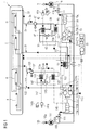
- Fig. 1 shows a system 1 comprising an energy supply arrangement for generating and supplying electrical energy in an airplane.
- the system 1 can be applied to other types of vehicles with an engine that outputs hot air.
- a jet engine 3 of an airplane has a bleed air output line 5a leading bleed air from a sixth stage of the engine 3 downstream through a bleed air heat exchanger 7, which can use the hot bleed air from the engine 3 to heat an airplane cabin. Downstream of the bleed air heat exchanger 7 there is a confluence point 9. Bleed air from a second jet engine 103 can flow through a second bleed air output line 105a past an engine valve 12 configured to control the amount of bleed air from the second engine 103. The bleed air from the second engine 103 is added to the bleed air from the first jet engine 3 at the confluence point 9, which then flows through a bleed air input line 5b with a bleed air valve 11 to a turbo generator 13.
- the turbo generator 13 comprises in a successive order two turbines 15a, 15b in line, a gearbox 17, two variable frequency generators 19a, 19b, and two DC (Direct Current) converters 21a, 21b.
- any other number of turbines 15a, 15b may be chosen, such as one or three, for example.
- the two turbines 15a, 15b each drive one of the two variable frequency generators 19a, 19b, they may also together drive only one variable frequency generator 19a, 19b.
- a generator with variable frequency a generator with constant frequency or HVDC (high-voltage direct current) is used.
- the generators 19a, 19b may be operated isolated form the electrical network of the vehicle, which does not affect certification of the electrical vehicle system, for example that of an aircraft.
- the generators 19a, 19b may be an integral part of the electrical network of the vehicle, thus allowing to reduce the number of engine driven generators and/or to provide a higher reliability for the electrical power generation.
- the two DC converters 21a, 21b which very well may be AC converters, convert the electrical energy into an appropriate voltage level for electrical consumers A, B, C, D, here 270 VDC (Voltage Direct Current).
- the consumers A, B, C, D are four, but may be any number.
- An integrated or separated APU (Auxiliary Power Unit) 55 of the conventional kind, i.e. powered by fossil fuels, may further be provided in order to take over the energy supply of the consumers A, B, C, D, in case of a malfunction of the above system 1.
- Fig. 1 further shows that the system 1 comprises a cooling arrangement.
- a cooling circuit 31 comprises a consumer cooling line 33 passing the consumers A, B, C, D and absorbing their heat in a cooling fluid flowing through the consumer cooling line 33 past a pressure reservoir 35 and a subsequently arranged cooling fluid pump 37. Downstream of the pump 37 a diffluence point 39 of the consumer cooling line 33 separates the consumer cooling line 33 into two branched consumer cooling lines 33a, 33b.
- the first branched consumer cooling line 33a leads through a ram air heat exchanger 41 configured to cool the cooling fluid inside the first branched consumer cooling line 33a by ram air fed through a NACA scoop 41a or a ram air scoop 41b of the airplane.
- ram air is led through a ram air cooling line 42, which has a valve configured to control the amount of ram air reaching the ram air heat exchanger 41.
- the second branched consumer cooling line 33b leads through an expanded bleed air- / exhaust air heat exchanger 43 configured to cool the cooling fluid inside the first branched consumer cooling line 33b by the expanded bleed- / exhausted air from the turbines 15a, 15b fed through an expanded bleed air output line 45.
- a solenoid valve 49 is installed in the second branched consumer cooling line 33b downstream of the expanded bleed air heat exchanger 43.
- the solenoid valve 49 may alternatively be installed upstream of the expanded bleed air heat exchanger 43 in the second branched consumer cooling line 33b.
- the now cooled down consumer cooling fluid is led through the consumer cooling line 33 to a turbo generator heat exchanger 51, where a turbo generator cooling circuit 53 transporting heat from the converters 21a, 21b is fed through and cooled by the consumer cooling fluid.
- the cooling fluid used in the system being be a fluid, may in particular be a liquid or more particularly oil.
- the consumer cooling fluid flows through the consumer cooling line 33 to the consumers A, B, C, D, thereby closing the consumer cooling circuit 31.
- the heat exchangers 7, 41, 43, 51 may be tubular or plate-fin heat exchangers, for example.
- the ram air heat exchanger 41 may instead be an ambient air heat exchanger 41 mounted on a skin of the vehicle and cooled by ambient air.
- the above described elements of the system 1 on the right side of Fig. 1 are basically horizontally mirrored on the left side of Fig. 1 in order to increase safety of the entire system 1, for example if one side has a malfunction.
- the system 1 has two common consumer cooling circuits 31, 133 and two independent turbo generator cooling circuits 53, 153.
- the two turbo generator cooling circuits 53, 153 may also be made common.
- the above system 1 can generate electrical power by using bleed air from an engine 3, 103 and cool electrical consumers A, B, C, D by reusing the expanded bleed air.
Landscapes
- Engineering & Computer Science (AREA)
- Chemical & Material Sciences (AREA)
- Combustion & Propulsion (AREA)
- Mechanical Engineering (AREA)
- General Engineering & Computer Science (AREA)
- Control Of Eletrric Generators (AREA)
Abstract
the turbo generator (13) has a bleed air input line (5b) connected to the bleed air output line (5a) of the engine (3) and is confgured to be powered by bleed air from the engine (3).
Description
- The invention relates to a system and method for generating electrical energy in a vehicle, as well as to a use of such system and method.
- Conventional systems and methods for generating electrical energy in a vehicle rely on fossil fuels.
- A problem to be solved by the present invention is to provide a system and/or method for generating electrical energy in a vehicle in an efficient manner.
- This problem is solved by a system and method with the features according to the respective independent claims.
- The system for generating electrical energy in a vehicle comprises an engine having a bleed air output line, a turbo generator connected to the engine, and an electrical consumer connected to the turbo generator, wherein the turbo generator has a bleed air input line connected to the bleed air output line of the engine and is configured to be powered by bleed air from the engine, preferably the engine being a jet engine, preferably the turbo generator comprising at least one turbine, preferably two turbines in line, preferably being configured to drive at least one electrical generator with variable frequency or an electrical generator with constant frequency or HVDC (high-voltage direct current), preferably each being configured to drive one electrical generator, preferably the electrical generator being connected to a DC (direct current) converter, preferably the DC converter being connected to the electrical consumer.
- The system may have a bleed air heat exchanger being arranged in the bleed air output line between the engine and the turbo generator, preferably the bleed air output line being configured to output bleed air from at least a sixth stage of the jet engine, preferably from only the sixth stage of the jet engine.
- The system may have a bleed air valve being arranged in the bleed air input line between the engine and the turbo generator, preferably between the bleed air heat exchanger and the turbo generator, preferably the bleed air valve being a solenoid valve or a butterfly valve.
- The system may have a gearbox being connected to the turbine, preferably the gearbox being in between the turbine and the electrical generator.
- In the system, the turbo generator may comprise an expanded bleed air output line which is configured to lead the expanded bleed air from the turbo generator, preferably from the turbine, wherein the expanded bleed air output line is connected to an expanded bleed air heat exchanger configured to cool the electrical consumer.
- In the latter system, the electrical consumer may be cooled by ambient or ram air through an ambient air- or ram air heat exchanger, preferably by ram air from an air scoop and/or a NACA scoop, preferably of an aircraft, preferably of an airplane. Providing both, an expanded bleed air heat exchanger and a ram air heat exchanger is advantageous, because the expanded bleed air heat exchanger can take up to 25% of the cooling load, such that ram air consumption and drag of the ram air heat exchanger can be reduced.
- Additionally, in the latter system, the ram air heat exchanger and the expanded bleed air heat exchanger may be connected in parallel to cool a consumer cooling fluid flowing through a consumer cooling line, preferably an expanded bleed air heat exchanger valve being arranged downstream of the expanded bleed air heat exchanger and upstream of a confluence point of the respective sections of the consumer cooling line for the ram air heat exchanger and the expanded bleed air heat exchanger, or the ram air heat exchanger and the expanded bleed air heat exchanger may be connected in line to cool a consumer cooling fluid flowing through a consumer cooling line, wherein the expanded bleed air heat exchanger being arranged downstream of the ram air heat exchanger.
- Some of the above systems may comprise a mechanical pump being arranged upstream of the expanded bleed air heat exchanger, preferably upstream of the ram air heat exchanger, preferably upstream of a diffluence point of the consumer cooling line, preferably a pressure reservoir being connected to the consumer cooling line upstream of the mechanical pump.
- In any of the above systems the bleed air input line of the turbo generator may be connected to a second bleed air output line of a second engine and the turbo generator may be configured to be powered by bleed air from the first engine and from the second engine, preferably with the bleed air valve in between the turbo generator and both engines, preferably with an engine valve upstream of the bleed air valve towards the second engine and in between both engines configured to control the amount of bleed air from the second engine reaching the bleed air valve, preferably the engine valve is a solenoid valve or a butterfly valve.
- In some of the above systems, a turbo generator heat exchanger may be connected to the turbo generator, preferably being configured to cool the electrical generator, preferably with the consumer cooling fluid of the consumer cooling line, preferably being arranged downstream of the ram air heat exchanger and/or the expanded bleed air heat exchanger, preferably being arranged upstream of the consumer. Thereby the turbo generator can be cooled, while enough cooling capacity is left in the consumer cooling fluid for the consumer.
- In some of the above systems, the consumer cooling line may be configured to cool multiple electrical consumers in parallel or in line.
- In some of the above systems, multiple consumer cooling lines may be configured to cool the electrical consumer.
- A method for generating electrical energy in a vehicle with one of the above systems comprises the step of:
- leading bleed air from an engine to a turbo generator.
- The Method may comprise the additional step of:
- using the expanded bleed air from the turbo generator for cooling a consumer cooling fluid in a consumer cooling line,
- and preferably for cooling a DC converter.
- A use of any one of the above systems or any one of the above methods in an aircraft is provided, preferably in an airplane.
- The invention will be further described under reference to the enclosed drawing, wherein similar elements have similar reference signs. In order to improve readability of the drawing, only some of the similar reference signs are provided while the other can obviously be derived by the skilled reader. In this drawing
- Fig. 1
- is a schematic of an energy supply and cooling arrangement.
-
Fig. 1 shows a system 1 comprising an energy supply arrangement for generating and supplying electrical energy in an airplane. Of course, the system 1 can be applied to other types of vehicles with an engine that outputs hot air. - Here, a jet engine 3 of an airplane has a bleed
air output line 5a leading bleed air from a sixth stage of the engine 3 downstream through a bleedair heat exchanger 7, which can use the hot bleed air from the engine 3 to heat an airplane cabin. Downstream of the bleedair heat exchanger 7 there is aconfluence point 9. Bleed air from asecond jet engine 103 can flow through a second bleedair output line 105a past anengine valve 12 configured to control the amount of bleed air from thesecond engine 103. The bleed air from thesecond engine 103 is added to the bleed air from the first jet engine 3 at theconfluence point 9, which then flows through a bleedair input line 5b with a bleed air valve 11 to aturbo generator 13. - The
turbo generator 13 comprises in a successive order twoturbines gearbox 17, two variable frequency generators 19a, 19b, and two DC (Direct Current) converters 21a, 21b. Of course, any other number ofturbines turbines - An integrated or separated APU (Auxiliary Power Unit) 55 of the conventional kind, i.e. powered by fossil fuels, may further be provided in order to take over the energy supply of the consumers A, B, C, D, in case of a malfunction of the above system 1.
-
Fig. 1 further shows that the system 1 comprises a cooling arrangement. - Here, a
cooling circuit 31 comprises aconsumer cooling line 33 passing the consumers A, B, C, D and absorbing their heat in a cooling fluid flowing through theconsumer cooling line 33 past apressure reservoir 35 and a subsequently arrangedcooling fluid pump 37. Downstream of the pump 37 adiffluence point 39 of theconsumer cooling line 33 separates theconsumer cooling line 33 into two branchedconsumer cooling lines - The first branched
consumer cooling line 33a leads through a ramair heat exchanger 41 configured to cool the cooling fluid inside the first branchedconsumer cooling line 33a by ram air fed through a NACAscoop 41a or aram air scoop 41b of the airplane. Such ram air is led through a ramair cooling line 42, which has a valve configured to control the amount of ram air reaching the ramair heat exchanger 41. - The second branched
consumer cooling line 33b leads through an expanded bleed air- / exhaustair heat exchanger 43 configured to cool the cooling fluid inside the first branchedconsumer cooling line 33b by the expanded bleed- / exhausted air from theturbines air output line 45. - Downstream of the ram
air heat exchanger 41 and the expanded bleedair heat exchanger 43 the two branchedconsumer cooling lines confluence point 47 from which the cooling fluid continues to flow inside theconsumer cooling line 33. In order to adjust the amount of cooling fluid reaching thisconfluence point 47, asolenoid valve 49 is installed in the second branchedconsumer cooling line 33b downstream of the expanded bleedair heat exchanger 43. Of course, thesolenoid valve 49 may alternatively be installed upstream of the expanded bleedair heat exchanger 43 in the second branchedconsumer cooling line 33b. - The now cooled down consumer cooling fluid is led through the
consumer cooling line 33 to a turbogenerator heat exchanger 51, where a turbogenerator cooling circuit 53 transporting heat from the converters 21a, 21b is fed through and cooled by the consumer cooling fluid. Of course, the cooling fluid used in the system being be a fluid, may in particular be a liquid or more particularly oil. - Finally, the consumer cooling fluid flows through the
consumer cooling line 33 to the consumers A, B, C, D, thereby closing theconsumer cooling circuit 31. - Here, the
heat exchangers air heat exchanger 41 may instead be an ambientair heat exchanger 41 mounted on a skin of the vehicle and cooled by ambient air. - As shown in
Fig. 1 , the above described elements of the system 1 on the right side ofFig. 1 are basically horizontally mirrored on the left side ofFig. 1 in order to increase safety of the entire system 1, for example if one side has a malfunction. Hence, the system 1 has two commonconsumer cooling circuits generator cooling circuits generator cooling circuits - In summary, the above system 1 can generate electrical power by using bleed air from an
engine 3, 103 and cool electrical consumers A, B, C, D by reusing the expanded bleed air.
Claims (15)
- System (1) for generating electrical energy in a vehicle, comprising
an engine (3) having a bleed air output line (5a),
a turbo generator (13) connected to the engine (3), and
an electrical consumer (A, B, C, D) connected to the turbo generator (13), wherein
the turbo generator (13) has a bleed air input line (5b) connected to the bleed air output line (5a) of the engine (3) and is configured to be powered by bleed air from the engine (3),
preferably the engine (3) being a jet engine,
preferably the turbo generator (13) comprising at least one turbine (15a; 15b),
preferably two turbines (15a, 15b) in line,
preferably being configured to drive at least one electrical generator (19a, 19b) with variable frequency or an electrical generator with constant frequency or HVDC,
preferably each being configured to drive one electrical generator (19a; 19b), preferably the electrical generator (19a, 19b) being connected to a DC converter (21a; 21b),
preferably the DC converter (21a; 21b) being connected to the electrical consumer (A, B, C, D). - System (1) according to claim 1, wherein
a bleed air heat exchanger (7) is arranged in the bleed air output line (5a) between the engine (3) and the turbo generator (13),
preferably the bleed air output line (5a) being configured to output bleed air from at least a sixth stage of the jet engine (3),
preferably from only the sixth stage of the jet engine (3). - System (1) according to claim 1 or 2, wherein
a bleed air valve (11) is arranged in the bleed air input line (5b) between the engine (3) and the turbo generator (13),
preferably between the bleed air heat exchanger (7) and the turbo generator (13),
preferably the bleed air valve (11) being a solenoid valve or a butterfly valve. - System (1) according to any one of claims 1 to 3, wherein
a gearbox (17) is connected to the turbine (15a; 15b),
preferably the gearbox (17) being in between the turbine (15a; 15b) and the electrical generator (19a; 19b). - System (1) according to any one of claims 1 to 4, wherein
the turbo generator (13) comprises an expanded bleed air output line (45) which is configured to lead the expanded bleed air from the turbo generator (13),
preferably from the turbine (15a; 15b), wherein
the expanded bleed air output line (45) is connected to an expanded bleed air heat exchanger (43) configured to cool the electrical consumer (A, B, C, D). - System (1) according to claim 5, wherein
the electrical consumer (A, B, C, D) is cooled by ambient or ram air through an ambient air- or ram air heat exchanger (41),
preferably by ram air from a NACA scoop (41a) and/or an air scoop (41b), preferably of an aircraft,
preferably of an airplane. - System (1) according to claim 6, wherein
the ram air heat exchanger (41) and the expanded bleed air heat exchanger (43) are connected in parallel to cool a consumer cooling fluid flowing through a consumer cooling line (33),
preferably an expanded bleed air heat exchanger valve (49) being arranged downstream of the expanded bleed air heat exchanger (43) and upstream of a confluence point (47) of the respective sections (33a, 33b) of the consumer cooling line (33) for the ram air heat exchanger (41) and the expanded bleed air heat exchanger (43), or wherein
the ram air heat exchanger (41) and the expanded bleed air heat exchanger (43) are connected in line to cool a consumer cooling fluid flowing through a consumer cooling line (33),
preferably the expanded bleed air heat exchanger (43) being arranged downstream of the ram air heat exchanger (41). - System (1) according to any one of claims 5 to 7, wherein
a mechanical pump (37) is arranged upstream of the expanded bleed air heat exchanger (43),
preferably upstream of the ram air heat exchanger (41),
preferably upstream of a diffluence point (39) of the consumer cooling line (33),
preferably a pressure reservoir (35) being connected to the consumer cooling line (33) upstream of the mechanical pump (37). - System (1) according to any one of claims 1 to 8, wherein
the bleed air input line (5b) of the turbo generator (13) is connected to a second bleed air output line (105a) of a second engine (103) and the turbo generator (13) is configured to be powered by bleed air from the engine (3) and from the second engine (103),
preferably with the bleed air valve (11) in between the turbo generator (13) and both engines (3, 103),
preferably with an engine valve (12) upstream of the bleed air valve (11) towards the second engine (103) and in between both engines (3, 103) configured to control the amount of bleed air from the second engine (103) reaching the bleed air valve (11),
preferably the engine valve (12) is a solenoid valve or a butterfly valve. - System (1) according to any one of claims 5 to 11, wherein
a turbo generator heat exchanger (51) is connected to the turbo generator ( 13),
preferably being configured to cool the electrical generator (21a; 21b),
preferably with the consumer cooling fluid of the consumer cooling line (33),
preferably being arranged downstream of the ram air heat exchanger (41) and/or the expanded bleed air heat exchanger (43). - System (1) according to any one of claims 7 to 10, wherein
the consumer cooling line (33) is configured to cool multiple electrical consumers (A, B, C, D) in parallel or in line. - System (1) according to any one of claims 7 to 11, wherein
multiple consumer cooling lines (33, 133) are configured to cool the electrical consumer (A, B, C, D). - Method for generating electrical energy in a vehicle with a system (1) according to any one of the preceding claims, comprising the step of:- leading bleed air from an engine (3) to a turbo generator (13).
- Method according to claim 13, comprising the additional step of:- using the expanded bleed air from the turbo generator (13) for cooling a consumer cooling fluid in a consumer cooling line (33),- and preferably for cooling a DC converter (21a; 21b).
- Use of the system (1) according to any one of claims 1 to 12 or the method according to any one of claims 13 and 14 in an aircraft, preferably an airplane.
Priority Applications (1)
| Application Number | Priority Date | Filing Date | Title |
|---|---|---|---|
| EP16290122.7A EP3263866B1 (en) | 2016-06-29 | 2016-06-29 | System and method for generating electrical energy in a vehicle |
Applications Claiming Priority (1)
| Application Number | Priority Date | Filing Date | Title |
|---|---|---|---|
| EP16290122.7A EP3263866B1 (en) | 2016-06-29 | 2016-06-29 | System and method for generating electrical energy in a vehicle |
Publications (2)
| Publication Number | Publication Date |
|---|---|
| EP3263866A1 true EP3263866A1 (en) | 2018-01-03 |
| EP3263866B1 EP3263866B1 (en) | 2019-08-07 |
Family
ID=56567536
Family Applications (1)
| Application Number | Title | Priority Date | Filing Date |
|---|---|---|---|
| EP16290122.7A Active EP3263866B1 (en) | 2016-06-29 | 2016-06-29 | System and method for generating electrical energy in a vehicle |
Country Status (1)
| Country | Link |
|---|---|
| EP (1) | EP3263866B1 (en) |
Cited By (1)
| Publication number | Priority date | Publication date | Assignee | Title |
|---|---|---|---|---|
| EP3733520A1 (en) * | 2019-04-29 | 2020-11-04 | Hamilton Sundstrand Corporation | Thermal management system with cooling turbine and generator |
Citations (4)
| Publication number | Priority date | Publication date | Assignee | Title |
|---|---|---|---|---|
| WO2002066324A2 (en) * | 2001-02-16 | 2002-08-29 | Hamilton Sundstrand Corporation | Improved aircraft system architecture |
| WO2003019767A1 (en) * | 2001-08-24 | 2003-03-06 | Smiths Aerospace, Inc., Electronic Systems-Rockford | System and method for providing ballast loading for a turbo-generator |
| EP2527603A2 (en) * | 2011-05-27 | 2012-11-28 | General Electric Company | Flade Duct Turbine Cooling And Power And Thermal Management |
| US9328661B2 (en) * | 2011-11-03 | 2016-05-03 | Northrop Grumman Systems Corporation | Apparatus for aircraft with high peak power equipment |
-
2016
- 2016-06-29 EP EP16290122.7A patent/EP3263866B1/en active Active
Patent Citations (4)
| Publication number | Priority date | Publication date | Assignee | Title |
|---|---|---|---|---|
| WO2002066324A2 (en) * | 2001-02-16 | 2002-08-29 | Hamilton Sundstrand Corporation | Improved aircraft system architecture |
| WO2003019767A1 (en) * | 2001-08-24 | 2003-03-06 | Smiths Aerospace, Inc., Electronic Systems-Rockford | System and method for providing ballast loading for a turbo-generator |
| EP2527603A2 (en) * | 2011-05-27 | 2012-11-28 | General Electric Company | Flade Duct Turbine Cooling And Power And Thermal Management |
| US9328661B2 (en) * | 2011-11-03 | 2016-05-03 | Northrop Grumman Systems Corporation | Apparatus for aircraft with high peak power equipment |
Cited By (2)
| Publication number | Priority date | Publication date | Assignee | Title |
|---|---|---|---|---|
| EP3733520A1 (en) * | 2019-04-29 | 2020-11-04 | Hamilton Sundstrand Corporation | Thermal management system with cooling turbine and generator |
| US11286857B2 (en) | 2019-04-29 | 2022-03-29 | Hamilton Sundstrand Corporation | Turbine-turbine generator power thermal management system |
Also Published As
| Publication number | Publication date |
|---|---|
| EP3263866B1 (en) | 2019-08-07 |
Similar Documents
| Publication | Publication Date | Title |
|---|---|---|
| Fard et al. | Aircraft distributed electric propulsion technologies—A review | |
| Buticchi et al. | The more-electric aircraft and beyond | |
| Sarlioglu et al. | More electric aircraft: Review, challenges, and opportunities for commercial transport aircraft | |
| US8662445B2 (en) | Hybrid power system architecture for an aircraft | |
| Roboam et al. | More electricity in the air: Toward optimized electrical networks embedded in more-electrical aircraft | |
| US10823066B2 (en) | Thermal management system | |
| Jones et al. | Comparison of candidate architectures for future distributed propulsion aircraft | |
| US10260419B2 (en) | Cooling system | |
| US11661197B2 (en) | Cabin outflow air energy optimized cabin pressurizing system | |
| US9885289B2 (en) | Aircraft propulsion architecture integrating an energy recovery system | |
| US10309303B2 (en) | Systems and methods of generating electrical power | |
| CN105523190B (en) | Aircraft auxiliary power system and method | |
| Davies et al. | A review of turboelectric distributed propulsion technologies for N+ 3 aircraft electrical systems | |
| Pornet et al. | Methodology for sizing and performance assessment of hybrid energy aircraft | |
| CN103057716A (en) | Multiple source electrical power distribution in aircraft | |
| US20150349356A1 (en) | Hybrid emergency power unit system | |
| Arabul et al. | Perspectives and development of electrical systems in more electric aircraft | |
| Vratny et al. | Sizing considerations of an electric ducted fan for hybrid energy aircraft | |
| Bielsky et al. | Overall parametric design and integration of on-board systems for a hydrogen-powered concept aircraft | |
| US9162773B2 (en) | Aircraft comprising a reversible rotary electrical machine | |
| EP1099630A2 (en) | Power supply system for an aircraft | |
| Pontika et al. | Integrated mission performance analysis of novel propulsion systems: Analysis of a fuel cell regional aircraft retrofit | |
| Parrilla | Hybrid environmental control system integrated modeling trade study analysis for commercial aviation | |
| EP3263866B1 (en) | System and method for generating electrical energy in a vehicle | |
| US20110254284A1 (en) | Electrical generation |
Legal Events
| Date | Code | Title | Description |
|---|---|---|---|
| PUAI | Public reference made under article 153(3) epc to a published international application that has entered the european phase |
Free format text: ORIGINAL CODE: 0009012 |
|
| STAA | Information on the status of an ep patent application or granted ep patent |
Free format text: STATUS: THE APPLICATION HAS BEEN PUBLISHED |
|
| AK | Designated contracting states |
Kind code of ref document: A1 Designated state(s): AL AT BE BG CH CY CZ DE DK EE ES FI FR GB GR HR HU IE IS IT LI LT LU LV MC MK MT NL NO PL PT RO RS SE SI SK SM TR |
|
| AX | Request for extension of the european patent |
Extension state: BA ME |
|
| STAA | Information on the status of an ep patent application or granted ep patent |
Free format text: STATUS: REQUEST FOR EXAMINATION WAS MADE |
|
| 17P | Request for examination filed |
Effective date: 20180214 |
|
| RBV | Designated contracting states (corrected) |
Designated state(s): AL AT BE BG CH CY CZ DE DK EE ES FI FR GB GR HR HU IE IS IT LI LT LU LV MC MK MT NL NO PL PT RO RS SE SI SK SM TR |
|
| STAA | Information on the status of an ep patent application or granted ep patent |
Free format text: STATUS: EXAMINATION IS IN PROGRESS |
|
| 17Q | First examination report despatched |
Effective date: 20180925 |
|
| GRAP | Despatch of communication of intention to grant a patent |
Free format text: ORIGINAL CODE: EPIDOSNIGR1 |
|
| STAA | Information on the status of an ep patent application or granted ep patent |
Free format text: STATUS: GRANT OF PATENT IS INTENDED |
|
| INTG | Intention to grant announced |
Effective date: 20190325 |
|
| GRAS | Grant fee paid |
Free format text: ORIGINAL CODE: EPIDOSNIGR3 |
|
| GRAA | (expected) grant |
Free format text: ORIGINAL CODE: 0009210 |
|
| STAA | Information on the status of an ep patent application or granted ep patent |
Free format text: STATUS: THE PATENT HAS BEEN GRANTED |
|
| AK | Designated contracting states |
Kind code of ref document: B1 Designated state(s): AL AT BE BG CH CY CZ DE DK EE ES FI FR GB GR HR HU IE IS IT LI LT LU LV MC MK MT NL NO PL PT RO RS SE SI SK SM TR |
|
| REG | Reference to a national code |
Ref country code: GB Ref legal event code: FG4D |
|
| REG | Reference to a national code |
Ref country code: CH Ref legal event code: EP Ref country code: AT Ref legal event code: REF Ref document number: 1164235 Country of ref document: AT Kind code of ref document: T Effective date: 20190815 |
|
| REG | Reference to a national code |
Ref country code: DE Ref legal event code: R096 Ref document number: 602016018048 Country of ref document: DE |
|
| REG | Reference to a national code |
Ref country code: IE Ref legal event code: FG4D |
|
| REG | Reference to a national code |
Ref country code: NL Ref legal event code: MP Effective date: 20190807 |
|
| REG | Reference to a national code |
Ref country code: LT Ref legal event code: MG4D |
|
| PG25 | Lapsed in a contracting state [announced via postgrant information from national office to epo] |
Ref country code: SE Free format text: LAPSE BECAUSE OF FAILURE TO SUBMIT A TRANSLATION OF THE DESCRIPTION OR TO PAY THE FEE WITHIN THE PRESCRIBED TIME-LIMIT Effective date: 20190807 Ref country code: HR Free format text: LAPSE BECAUSE OF FAILURE TO SUBMIT A TRANSLATION OF THE DESCRIPTION OR TO PAY THE FEE WITHIN THE PRESCRIBED TIME-LIMIT Effective date: 20190807 Ref country code: BG Free format text: LAPSE BECAUSE OF FAILURE TO SUBMIT A TRANSLATION OF THE DESCRIPTION OR TO PAY THE FEE WITHIN THE PRESCRIBED TIME-LIMIT Effective date: 20191107 Ref country code: NL Free format text: LAPSE BECAUSE OF FAILURE TO SUBMIT A TRANSLATION OF THE DESCRIPTION OR TO PAY THE FEE WITHIN THE PRESCRIBED TIME-LIMIT Effective date: 20190807 Ref country code: PT Free format text: LAPSE BECAUSE OF FAILURE TO SUBMIT A TRANSLATION OF THE DESCRIPTION OR TO PAY THE FEE WITHIN THE PRESCRIBED TIME-LIMIT Effective date: 20191209 Ref country code: LT Free format text: LAPSE BECAUSE OF FAILURE TO SUBMIT A TRANSLATION OF THE DESCRIPTION OR TO PAY THE FEE WITHIN THE PRESCRIBED TIME-LIMIT Effective date: 20190807 Ref country code: FI Free format text: LAPSE BECAUSE OF FAILURE TO SUBMIT A TRANSLATION OF THE DESCRIPTION OR TO PAY THE FEE WITHIN THE PRESCRIBED TIME-LIMIT Effective date: 20190807 Ref country code: NO Free format text: LAPSE BECAUSE OF FAILURE TO SUBMIT A TRANSLATION OF THE DESCRIPTION OR TO PAY THE FEE WITHIN THE PRESCRIBED TIME-LIMIT Effective date: 20191107 |
|
| REG | Reference to a national code |
Ref country code: AT Ref legal event code: MK05 Ref document number: 1164235 Country of ref document: AT Kind code of ref document: T Effective date: 20190807 |
|
| PG25 | Lapsed in a contracting state [announced via postgrant information from national office to epo] |
Ref country code: IS Free format text: LAPSE BECAUSE OF FAILURE TO SUBMIT A TRANSLATION OF THE DESCRIPTION OR TO PAY THE FEE WITHIN THE PRESCRIBED TIME-LIMIT Effective date: 20191207 Ref country code: GR Free format text: LAPSE BECAUSE OF FAILURE TO SUBMIT A TRANSLATION OF THE DESCRIPTION OR TO PAY THE FEE WITHIN THE PRESCRIBED TIME-LIMIT Effective date: 20191108 Ref country code: RS Free format text: LAPSE BECAUSE OF FAILURE TO SUBMIT A TRANSLATION OF THE DESCRIPTION OR TO PAY THE FEE WITHIN THE PRESCRIBED TIME-LIMIT Effective date: 20190807 Ref country code: ES Free format text: LAPSE BECAUSE OF FAILURE TO SUBMIT A TRANSLATION OF THE DESCRIPTION OR TO PAY THE FEE WITHIN THE PRESCRIBED TIME-LIMIT Effective date: 20190807 Ref country code: AL Free format text: LAPSE BECAUSE OF FAILURE TO SUBMIT A TRANSLATION OF THE DESCRIPTION OR TO PAY THE FEE WITHIN THE PRESCRIBED TIME-LIMIT Effective date: 20190807 Ref country code: LV Free format text: LAPSE BECAUSE OF FAILURE TO SUBMIT A TRANSLATION OF THE DESCRIPTION OR TO PAY THE FEE WITHIN THE PRESCRIBED TIME-LIMIT Effective date: 20190807 |
|
| PG25 | Lapsed in a contracting state [announced via postgrant information from national office to epo] |
Ref country code: TR Free format text: LAPSE BECAUSE OF FAILURE TO SUBMIT A TRANSLATION OF THE DESCRIPTION OR TO PAY THE FEE WITHIN THE PRESCRIBED TIME-LIMIT Effective date: 20190807 |
|
| PG25 | Lapsed in a contracting state [announced via postgrant information from national office to epo] |
Ref country code: DK Free format text: LAPSE BECAUSE OF FAILURE TO SUBMIT A TRANSLATION OF THE DESCRIPTION OR TO PAY THE FEE WITHIN THE PRESCRIBED TIME-LIMIT Effective date: 20190807 Ref country code: AT Free format text: LAPSE BECAUSE OF FAILURE TO SUBMIT A TRANSLATION OF THE DESCRIPTION OR TO PAY THE FEE WITHIN THE PRESCRIBED TIME-LIMIT Effective date: 20190807 Ref country code: IT Free format text: LAPSE BECAUSE OF FAILURE TO SUBMIT A TRANSLATION OF THE DESCRIPTION OR TO PAY THE FEE WITHIN THE PRESCRIBED TIME-LIMIT Effective date: 20190807 Ref country code: EE Free format text: LAPSE BECAUSE OF FAILURE TO SUBMIT A TRANSLATION OF THE DESCRIPTION OR TO PAY THE FEE WITHIN THE PRESCRIBED TIME-LIMIT Effective date: 20190807 Ref country code: RO Free format text: LAPSE BECAUSE OF FAILURE TO SUBMIT A TRANSLATION OF THE DESCRIPTION OR TO PAY THE FEE WITHIN THE PRESCRIBED TIME-LIMIT Effective date: 20190807 Ref country code: PL Free format text: LAPSE BECAUSE OF FAILURE TO SUBMIT A TRANSLATION OF THE DESCRIPTION OR TO PAY THE FEE WITHIN THE PRESCRIBED TIME-LIMIT Effective date: 20190807 |
|
| PG25 | Lapsed in a contracting state [announced via postgrant information from national office to epo] |
Ref country code: SM Free format text: LAPSE BECAUSE OF FAILURE TO SUBMIT A TRANSLATION OF THE DESCRIPTION OR TO PAY THE FEE WITHIN THE PRESCRIBED TIME-LIMIT Effective date: 20190807 Ref country code: SK Free format text: LAPSE BECAUSE OF FAILURE TO SUBMIT A TRANSLATION OF THE DESCRIPTION OR TO PAY THE FEE WITHIN THE PRESCRIBED TIME-LIMIT Effective date: 20190807 Ref country code: CZ Free format text: LAPSE BECAUSE OF FAILURE TO SUBMIT A TRANSLATION OF THE DESCRIPTION OR TO PAY THE FEE WITHIN THE PRESCRIBED TIME-LIMIT Effective date: 20190807 Ref country code: IS Free format text: LAPSE BECAUSE OF FAILURE TO SUBMIT A TRANSLATION OF THE DESCRIPTION OR TO PAY THE FEE WITHIN THE PRESCRIBED TIME-LIMIT Effective date: 20200224 |
|
| REG | Reference to a national code |
Ref country code: DE Ref legal event code: R097 Ref document number: 602016018048 Country of ref document: DE |
|
| PLBE | No opposition filed within time limit |
Free format text: ORIGINAL CODE: 0009261 |
|
| STAA | Information on the status of an ep patent application or granted ep patent |
Free format text: STATUS: NO OPPOSITION FILED WITHIN TIME LIMIT |
|
| PG2D | Information on lapse in contracting state deleted |
Ref country code: IS |
|
| 26N | No opposition filed |
Effective date: 20200603 |
|
| PG25 | Lapsed in a contracting state [announced via postgrant information from national office to epo] |
Ref country code: SI Free format text: LAPSE BECAUSE OF FAILURE TO SUBMIT A TRANSLATION OF THE DESCRIPTION OR TO PAY THE FEE WITHIN THE PRESCRIBED TIME-LIMIT Effective date: 20190807 |
|
| PG25 | Lapsed in a contracting state [announced via postgrant information from national office to epo] |
Ref country code: MC Free format text: LAPSE BECAUSE OF FAILURE TO SUBMIT A TRANSLATION OF THE DESCRIPTION OR TO PAY THE FEE WITHIN THE PRESCRIBED TIME-LIMIT Effective date: 20190807 |
|
| REG | Reference to a national code |
Ref country code: CH Ref legal event code: PL |
|
| PG25 | Lapsed in a contracting state [announced via postgrant information from national office to epo] |
Ref country code: LU Free format text: LAPSE BECAUSE OF NON-PAYMENT OF DUE FEES Effective date: 20200629 |
|
| REG | Reference to a national code |
Ref country code: BE Ref legal event code: MM Effective date: 20200630 |
|
| PG25 | Lapsed in a contracting state [announced via postgrant information from national office to epo] |
Ref country code: CH Free format text: LAPSE BECAUSE OF NON-PAYMENT OF DUE FEES Effective date: 20200630 Ref country code: IE Free format text: LAPSE BECAUSE OF NON-PAYMENT OF DUE FEES Effective date: 20200629 Ref country code: LI Free format text: LAPSE BECAUSE OF NON-PAYMENT OF DUE FEES Effective date: 20200630 |
|
| PG25 | Lapsed in a contracting state [announced via postgrant information from national office to epo] |
Ref country code: BE Free format text: LAPSE BECAUSE OF NON-PAYMENT OF DUE FEES Effective date: 20200630 |
|
| PG25 | Lapsed in a contracting state [announced via postgrant information from national office to epo] |
Ref country code: MT Free format text: LAPSE BECAUSE OF FAILURE TO SUBMIT A TRANSLATION OF THE DESCRIPTION OR TO PAY THE FEE WITHIN THE PRESCRIBED TIME-LIMIT Effective date: 20190807 Ref country code: CY Free format text: LAPSE BECAUSE OF FAILURE TO SUBMIT A TRANSLATION OF THE DESCRIPTION OR TO PAY THE FEE WITHIN THE PRESCRIBED TIME-LIMIT Effective date: 20190807 |
|
| PG25 | Lapsed in a contracting state [announced via postgrant information from national office to epo] |
Ref country code: MK Free format text: LAPSE BECAUSE OF FAILURE TO SUBMIT A TRANSLATION OF THE DESCRIPTION OR TO PAY THE FEE WITHIN THE PRESCRIBED TIME-LIMIT Effective date: 20190807 |
|
| PGFP | Annual fee paid to national office [announced via postgrant information from national office to epo] |
Ref country code: DE Payment date: 20250618 Year of fee payment: 10 |
|
| PGFP | Annual fee paid to national office [announced via postgrant information from national office to epo] |
Ref country code: GB Payment date: 20250618 Year of fee payment: 10 |
|
| PGFP | Annual fee paid to national office [announced via postgrant information from national office to epo] |
Ref country code: FR Payment date: 20250625 Year of fee payment: 10 |