EP3263863A1 - Intake system piping structure for internal combustion engine - Google Patents
Intake system piping structure for internal combustion engine Download PDFInfo
- Publication number
- EP3263863A1 EP3263863A1 EP15883118.0A EP15883118A EP3263863A1 EP 3263863 A1 EP3263863 A1 EP 3263863A1 EP 15883118 A EP15883118 A EP 15883118A EP 3263863 A1 EP3263863 A1 EP 3263863A1
- Authority
- EP
- European Patent Office
- Prior art keywords
- cylinder
- intercooler
- combustion engine
- internal combustion
- intake
- Prior art date
- Legal status (The legal status is an assumption and is not a legal conclusion. Google has not performed a legal analysis and makes no representation as to the accuracy of the status listed.)
- Withdrawn
Links
- 238000002485 combustion reaction Methods 0.000 title claims abstract description 65
- 230000000052 comparative effect Effects 0.000 description 16
- 230000006835 compression Effects 0.000 description 1
- 238000007906 compression Methods 0.000 description 1
- 230000000694 effects Effects 0.000 description 1
Images


Classifications
-
- F—MECHANICAL ENGINEERING; LIGHTING; HEATING; WEAPONS; BLASTING
- F02—COMBUSTION ENGINES; HOT-GAS OR COMBUSTION-PRODUCT ENGINE PLANTS
- F02M—SUPPLYING COMBUSTION ENGINES IN GENERAL WITH COMBUSTIBLE MIXTURES OR CONSTITUENTS THEREOF
- F02M35/00—Combustion-air cleaners, air intakes, intake silencers, or induction systems specially adapted for, or arranged on, internal-combustion engines
- F02M35/10—Air intakes; Induction systems
- F02M35/10091—Air intakes; Induction systems characterised by details of intake ducts: shapes; connections; arrangements
- F02M35/10144—Connections of intake ducts to each other or to another device
-
- F—MECHANICAL ENGINEERING; LIGHTING; HEATING; WEAPONS; BLASTING
- F02—COMBUSTION ENGINES; HOT-GAS OR COMBUSTION-PRODUCT ENGINE PLANTS
- F02B—INTERNAL-COMBUSTION PISTON ENGINES; COMBUSTION ENGINES IN GENERAL
- F02B29/00—Engines characterised by provision for charging or scavenging not provided for in groups F02B25/00, F02B27/00 or F02B33/00 - F02B39/00; Details thereof
- F02B29/04—Cooling of air intake supply
-
- F—MECHANICAL ENGINEERING; LIGHTING; HEATING; WEAPONS; BLASTING
- F02—COMBUSTION ENGINES; HOT-GAS OR COMBUSTION-PRODUCT ENGINE PLANTS
- F02B—INTERNAL-COMBUSTION PISTON ENGINES; COMBUSTION ENGINES IN GENERAL
- F02B29/00—Engines characterised by provision for charging or scavenging not provided for in groups F02B25/00, F02B27/00 or F02B33/00 - F02B39/00; Details thereof
- F02B29/04—Cooling of air intake supply
- F02B29/0406—Layout of the intake air cooling or coolant circuit
-
- F—MECHANICAL ENGINEERING; LIGHTING; HEATING; WEAPONS; BLASTING
- F02—COMBUSTION ENGINES; HOT-GAS OR COMBUSTION-PRODUCT ENGINE PLANTS
- F02B—INTERNAL-COMBUSTION PISTON ENGINES; COMBUSTION ENGINES IN GENERAL
- F02B29/00—Engines characterised by provision for charging or scavenging not provided for in groups F02B25/00, F02B27/00 or F02B33/00 - F02B39/00; Details thereof
- F02B29/04—Cooling of air intake supply
- F02B29/045—Constructional details of the heat exchangers, e.g. pipes, plates, ribs, insulation, materials, or manufacturing and assembly
- F02B29/0475—Constructional details of the heat exchangers, e.g. pipes, plates, ribs, insulation, materials, or manufacturing and assembly the intake air cooler being combined with another device, e.g. heater, valve, compressor, filter or EGR cooler, or being assembled on a special engine location
-
- F—MECHANICAL ENGINEERING; LIGHTING; HEATING; WEAPONS; BLASTING
- F02—COMBUSTION ENGINES; HOT-GAS OR COMBUSTION-PRODUCT ENGINE PLANTS
- F02M—SUPPLYING COMBUSTION ENGINES IN GENERAL WITH COMBUSTIBLE MIXTURES OR CONSTITUENTS THEREOF
- F02M35/00—Combustion-air cleaners, air intakes, intake silencers, or induction systems specially adapted for, or arranged on, internal-combustion engines
- F02M35/10—Air intakes; Induction systems
- F02M35/10242—Devices or means connected to or integrated into air intakes; Air intakes combined with other engine or vehicle parts
- F02M35/10268—Heating, cooling or thermal insulating means
-
- F—MECHANICAL ENGINEERING; LIGHTING; HEATING; WEAPONS; BLASTING
- F02—COMBUSTION ENGINES; HOT-GAS OR COMBUSTION-PRODUCT ENGINE PLANTS
- F02M—SUPPLYING COMBUSTION ENGINES IN GENERAL WITH COMBUSTIBLE MIXTURES OR CONSTITUENTS THEREOF
- F02M35/00—Combustion-air cleaners, air intakes, intake silencers, or induction systems specially adapted for, or arranged on, internal-combustion engines
- F02M35/10—Air intakes; Induction systems
- F02M35/104—Intake manifolds
- F02M35/1045—Intake manifolds characterised by the charge distribution between the cylinders/combustion chambers or its homogenisation
-
- F—MECHANICAL ENGINEERING; LIGHTING; HEATING; WEAPONS; BLASTING
- F02—COMBUSTION ENGINES; HOT-GAS OR COMBUSTION-PRODUCT ENGINE PLANTS
- F02M—SUPPLYING COMBUSTION ENGINES IN GENERAL WITH COMBUSTIBLE MIXTURES OR CONSTITUENTS THEREOF
- F02M35/00—Combustion-air cleaners, air intakes, intake silencers, or induction systems specially adapted for, or arranged on, internal-combustion engines
- F02M35/10—Air intakes; Induction systems
- F02M35/104—Intake manifolds
- F02M35/112—Intake manifolds for engines with cylinders all in one line
-
- Y—GENERAL TAGGING OF NEW TECHNOLOGICAL DEVELOPMENTS; GENERAL TAGGING OF CROSS-SECTIONAL TECHNOLOGIES SPANNING OVER SEVERAL SECTIONS OF THE IPC; TECHNICAL SUBJECTS COVERED BY FORMER USPC CROSS-REFERENCE ART COLLECTIONS [XRACs] AND DIGESTS
- Y02—TECHNOLOGIES OR APPLICATIONS FOR MITIGATION OR ADAPTATION AGAINST CLIMATE CHANGE
- Y02T—CLIMATE CHANGE MITIGATION TECHNOLOGIES RELATED TO TRANSPORTATION
- Y02T10/00—Road transport of goods or passengers
- Y02T10/10—Internal combustion engine [ICE] based vehicles
- Y02T10/12—Improving ICE efficiencies
Definitions
- the present invention relates to an intake system piping structure of an internal combustion engine.
- Some vehicle such as an automobile includes an intercooler to cool the intake air whose temperature is increased due to boost by a supercharger. By doing so, intake efficiency for a combustion chamber of an internal combustion engine of the vehicle can be enhanced.
- JP2009-270508A discloses an internal combustion engine with an intercooler in which an intake manifold and an intercooler are integrated.
- an intercooler in consideration with an allocation of the intake air, is arranged in such a manner that a cylinder bank direction center line of an internal combustion engine substantially matches a widthwise center line of the intercooler.
- the cylinder bank direction center line of the internal combustion engine indicates a center between axial center lines of two cylinders provided farthest from each other in a cylinder bank.
- An object of the present invention is to, even in a case where an intercooler cannot be arranged in such a manner that a cylinder bank direction center line of an internal combustion engine substantially matches a widthwise center line of the intercooler, make an allocation of the inflow air not remarkably different between cylinders.
- an intake system piping structure of an internal combustion engine includes an intake manifold connected to an end-side first cylinder and an end-side second cylinder which are provided farthest from each other in a cylinder bank in which a plurality of cylinders is placed in line, and an intercooler connected to the intake manifold.
- the intercooler is arranged in such a manner that a widthwise center of the intercooler on the side of an intake inlet and a widthwise center of the intercooler on the side of the manifold are offset to the side of the end-side second cylinder from a cylinder bank direction center line in center between an axial center line of the end-side first cylinder and an axial center line of the end-side second cylinder.
- the intercooler is also arranged in such a manner that an offset amount of the widthwise center of the intercooler on the side of the intake inlet from the cylinder bank direction center line is greater than an offset amount of the widthwise center of the intercooler on the side of the manifold from the cylinder bank direction center line.
- Fig. 1 is a front view of an internal combustion engine with an intercooler in the present embodiment.
- Fig. 2 is a plan view of the internal combustion engine with the intercooler in the present embodiment.
- the internal combustion engine 1 with the intercooler includes a liquid-cooled intercooler 11 (corresponding to an intercooler), an intake manifold 12, an intake air passage member 13, and a cylinder block 14.
- the internal combustion engine 1 with the intercooler also includes a first cylinder CY1 (corresponding to an end-side first cylinder), a second cylinder CY2, a third cylinder CY3, and a fourth cylinder CY4 (corresponding to an end-side second cylinder).
- An auxiliary machine such as an alternator 21 is arranged around the internal combustion engine 1 with the intercooler.
- the liquid-cooled intercooler 11 cools the air passing through an interior thereof.
- the liquid-cooled intercooler increases density of the intake air whose temperature is increased by compression by a supercharger or the like, and enhances intake efficiency for the cylinders.
- a flow passage in the liquid-cooled intercooler 11 is formed in such a shape that the intake air flows in the direction substantially along side surfaces 11s of the liquid-cooled intercooler 11 in an interior thereof.
- the liquid-cooled intercooler 11 is connected to an inlet of a manifold portion 12a.
- the intake manifold 12 includes the manifold portion 12a and branch portions 12b. Flow passages of the air in the manifold portion 12a and the branch portions 12b are also formed in shapes substantially along outer forms of these flow passages in interiors of these flow passages.
- the inlet of the manifold portion 12a is connected to an outlet of the liquid-cooled intercooler 11.
- the four branch portions 12b extend from the manifold portion 12a.
- the four branch portions 12b are connected to the cylinders CY1 to CY4 in the cylinder block 14.
- the intake air passage member 13 lets the intake air compressed by the supercharger (not shown) flow into the liquid-cooled intercooler 11.
- a flow passage in the intake air passage member 13 is also formed in the direction substantially along an outer form of the intake air passage member 13 in an interior of the intake air passage member 13.
- the intake air passage member 13 is connected to a bottom portion inlet (connection portion 11f) of the liquid-cooled intercooler 11 from the side of the fourth cylinder CY4.
- the cylinder block 14 includes four cylinders of the first cylinder CY1, the second cylinder CY2, the third cylinder CY3, and the fourth cylinder CY4.
- the first cylinder CY1, the second cylinder CY2, the third cylinder CY3, and the fourth cylinder CY4 are placed in line in the cylinder bank direction (in the left and right direction in Fig. 1 ).
- the first cylinder CY1 and the fourth cylinder CY4 are provided farthest from each other.
- the cylinders in the cylinder block 14 are connected to the four branch portions 12b of the intake manifold 12.
- Fig. 1 shows a cylinder bank direction center line C1 in center between an axial center line CT1 of the first cylinder CY1 and an axial center line CT4 of the fourth cylinder CY4.
- Fig. 1 also shows a widthwise center line C2 of the liquid-cooled intercooler 11.
- the widthwise center line C2 of the liquid-cooled intercooler 11 is a center line between the side walls 11s excluding a projection portion of the liquid-cooled intercooler 11 in the width direction of the liquid-cooled intercooler 11.
- Fig. 1 shows that a distance between the center line C2 and the left side wall 11s and a distance between the center line C"2 and the right side wall 11s are equally w.
- Fig. 1 also shows an orthogonal line CL orthogonal to the axial center line CT1 of the first cylinder CY1 and the axial center line CT4 of the fourth cylinder CY4.
- the liquid-cooled intercooler 11 is arranged in such a manner that a widthwise center C2a of the liquid-cooled intercooler 11 on the side of the intake inlet and a widthwise center C2b of the liquid-cooled intercooler 11 on the side of the intake manifold 12 are offset to the side of the fourth cylinder CY4 from the cylinder bank direction center line C1 in center between the axial center line CT1 of the first cylinder CY1 and the axial center line CT4 of the fourth cylinder CY4.
- the liquid-cooled intercooler 11 is also arranged in such a manner that an offset amount of the widthwise center C2a of the liquid-cooled intercooler 11 on the side of the intake inlet from the cylinder bank direction center line C1 is greater than an offset amount of the widthwise center C2b of the liquid-cooled intercooler 11 on the side of the intake manifold 12 from the cylinder bank direction center line C1.
- the liquid-cooled intercooler 11 is arranged to be inclined so that the widthwise center C2a of the liquid-cooled intercooler 11 on the side of the inlet of the liquid-cooled intercooler 11 is placed closer to the side of the fourth cylinder CY4 than the widthwise center C2b of the liquid-cooled intercooler 11 on the side of an outlet of the liquid-cooled intercooler 11.
- the liquid-cooled intercooler 11 is arranged in such a manner that the widthwise center C2 of the liquid-cooled intercooler 11 does not match the cylinder bank direction center line C1.
- the liquid-cooled intercooler 11 is provided closer to the fourth cylinder CY4 and the liquid-cooled intercooler 11 is arranged to be inclined so that the widthwise center C2a of the liquid-cooled intercooler 11 on the side of the inlet is placed closer to the fourth cylinder CY4 than the widthwise center C2b on the side of the outlet. Therefore, without providing a sharp curve point in the flow passage of the air flowing into the fourth cylinder CY4, the air can flow into the fourth cylinder CY4 by a route of arrows A1, A2 shown in Fig. 1 .
- the route of the air flowing into the fourth cylinder CY4 can be a route having no sharp curve point.
- the air can also flow into the fourth cylinder CY4 by the substantially same amount as the air flowing into the first cylinder CY1.
- an inflow amount of the air from the first cylinder CY1 to the fourth cylinder CY4 can be not remarkable different between the cylinders. It should be noted that effects of the present embodiment will be described in more detail in comparison to an internal combustion engine of comparative examples described later.
- the intake air passage member 13 is connected from the side of the fourth cylinder CY4 to the side of the intake inlet of the liquid-cooled intercooler 11.
- the intake air passage member 13 is arranged in such a manner that a bottom portion 13a of the intake air passage member 13 in the direction extending on the lower side of the liquid-cooled intercooler 11 is parallel to the orthogonal line CL.
- connection portion 11f between the liquid-cooled intercooler 11 and the intake air passage member 13 a sectional area thereof is enlarged as far as possible to enhance intake efficiency.
- the intake air passage member 13 is extended in such a manner that the bottom portion 13a thereof is parallel to the orthogonal line CL, and directly connected to the bottom portion of the liquid-cooled intercooler 11.
- the intake air passage member 13 does not stand upward but is directly connected to the bottom portion of the liquid-cooled intercooler 11 while extending in parallel to the orthogonal line CL. Therefore, up-down length of the entire intake system piping structure of the internal combustion engine 1 can be shortened, so that a compact internal combustion engine 1 can be provided.
- connection portion 11f between the intake air passage member 13 and the liquid-cooled intercooler 11 is the bottom portion of the liquid-cooled intercooler 11.
- a distance from the connection portion 11f to the bottom portion 13a of the intake air passage member 13 gradually becomes shorter.
- the intake air passage member 13 can be directly connected to the bottom portion of the liquid-cooled intercooler 11 to be parallel to the orthogonal line CL. Therefore, although the liquid-cooled intercooler 11 is inclined, the up-down length of the entire intake system piping structure of the internal combustion engine 1 can be shortened, so that a compact internal combustion engine 1 can be provided.
- the liquid-cooled intercooler 11 and the intake air passage member 13 are connected in such a manner that a lower end 11b of the liquid-cooled intercooler 11 on the side of the fourth cylinder CY4 matches an upper end 13b of a portion of the intake air passage member 13, the portion extending in parallel to the orthogonal line CL.
- a lower end 11c of the liquid-cooled intercooler 11 on the side of the first cylinder CY1 is arranged on the lower side of an upper end of the intake air passage member 13. Under such an arrangement relationship, the liquid-cooled intercooler 11 and the intake air passage member 13 are connected.
- the intake air passage member 13 can be directly connected to the bottom portion of the liquid-cooled intercooler 11. Therefore, the up-down length of the entire intake system piping structure of the internal combustion engine 1 can be shortened, so that a compact internal combustion engine 1 can be provided.
- the liquid-cooled intercooler 11 and the intake manifold 12 are connected in such a manner that an upper end 11d of the liquid-cooled intercooler 11 on the side of the fourth cylinder CY4 matches a lower surface 12c of the manifold portion 12a.
- An upper end 11e of the liquid-cooled intercooler 11 on the side of the first cylinder CY1 is arranged at a position lower than the lower surface 12c of the manifold portion 12a. Under such an arrangement relationship, the liquid-cooled intercooler 11 and the manifold portion 12a are connected.
- the right upper end 11d of the liquid-cooled intercooler 11 is directly connected to the lower surface 12c of the manifold portion 12a.
- the up-down length of the entire intake system piping structure of the internal combustion engine 1 can be shortened, so that a compact internal combustion engine 1 can be provided.
- Fig. 3 is a front view of an internal combustion engine with an intercooler in a first comparative example.
- the internal combustion engine 101 with the intercooler in the first comparative example includes a liquid-cooled intercooler 111, an intake manifold 112, an intake air passage member 113, and a cylinder block 114.
- the internal combustion engine 101 with the intercooler also includes a first cylinder CY1, a second cylinder CY2, a third cylinder CY3, and a fourth cylinder CY4.
- the reference signs are different.
- functions of the respective elements are the same as those of the present embodiment.
- the liquid-cooled intercooler 111 is arranged in such a manner that a cylinder bank direction center line C101 substantially matches a widthwise center line C102 of the liquid-cooled intercooler. In such a way, an intake allocation is not remarkably different between the cylinders.
- Fig. 4 is a front view of an internal combustion engine with an intercooler in a second comparative example.
- the internal combustion engine 201 with the intercooler in the second comparative example includes a liquid-cooled intercooler 211, an intake manifold 212, an intake air passage member 213, and a cylinder block 214.
- the internal combustion engine 201 with the intercooler also includes a first cylinder CY1, a second cylinder CY2, a third cylinder CY3, and a fourth cylinder CY4.
- the reference signs are different.
- functions of the respective elements are the same as those of the present embodiment.
- the alternator 121 cannot be arranged at a desired position due to contact with the liquid-cooled intercooler 111.
- the liquid-cooled intercooler 211 is arranged in such a manner that a widthwise center line C202 of the liquid-cooled intercooler 211 is offset to the side of the fourth cylinder CY4 (the right side in Fig. 4 ) from the cylinder bank direction center line C201.
- the internal combustion engine 1 in the present embodiment has the configuration as described above, the up-down length of the entire intake system piping structure of the internal combustion engine 1 can be shortened. Then, a compact internal combustion engine 1 can be provided. Thereby, there is an advantage that other auxiliary machine can be arranged or a working space can be provided on the lower side of the intake air passage member 13 for example.
- the first cylinder CY1 corresponds to the end-side first cylinder and the fourth cylinder CY4 corresponds to the end-side fourth cylinder.
- the fourth cylinder CY4 may correspond to the end-side first cylinder and the first cylinder CY1 may correspond to the end-side fourth cylinder.
- the liquid-cooled intercooler 11 is arranged in such a manner that the widthwise center C2b of the liquid-cooled intercooler 11 at the outlet of the liquid-cooled intercooler 11 is offset to the side of the first cylinder CY1 from the cylinder bank direction center line C1.
- the liquid-cooled intercooler 11 is arranged to be inclined in such a manner that the widthwise center C2a of the liquid-cooled intercooler 11 on the side of the inlet of the liquid-cooled intercooler 11 is placed closer to the side of the first cylinder CY1 than the widthwise center C2b of the liquid-cooled intercooler 11 on the side of the outlet of the liquid-cooled intercooler 11.
- the intake air passage member 13 is connected to the connection portion 11f of the liquid-cooled intercooler 11 from the side of the first cylinder CY1.
- the inline four internal combustion engine is described as an example.
- the number of cylinders may be more than this or less than this.
- the cylinders in both end portions of these cylinders correspond to the end-side first cylinder and the end-side second cylinder.
- the inline cylinder arrangement internal combustion engine is described as an example.
- the above embodiment can similarly be applied to one of two cylinder banks.
- three cylinders are placed in line in a V-6 internal combustion engine, the cylinders in both end portions of the three cylinders correspond to the end-side first cylinder and the end-side second cylinder.
- the liquid-cooled intercooler 11 is described as an example.
- the intercooler may be not the liquid-cooled intercooler but an air-cooled intercooler.
Landscapes
- Engineering & Computer Science (AREA)
- Chemical & Material Sciences (AREA)
- Combustion & Propulsion (AREA)
- Mechanical Engineering (AREA)
- General Engineering & Computer Science (AREA)
- Physics & Mathematics (AREA)
- Thermal Sciences (AREA)
- Supercharger (AREA)
- Characterised By The Charging Evacuation (AREA)
- Heat-Exchange Devices With Radiators And Conduit Assemblies (AREA)
Abstract
Description
- The present invention relates to an intake system piping structure of an internal combustion engine.
- Some vehicle such as an automobile includes an intercooler to cool the intake air whose temperature is increased due to boost by a supercharger. By doing so, intake efficiency for a combustion chamber of an internal combustion engine of the vehicle can be enhanced.
-
JP2009-270508A - In general design, in consideration with an allocation of the intake air, an intercooler is arranged in such a manner that a cylinder bank direction center line of an internal combustion engine substantially matches a widthwise center line of the intercooler. The cylinder bank direction center line of the internal combustion engine indicates a center between axial center lines of two cylinders provided farthest from each other in a cylinder bank.
- However, due to a situation of arrangement of an auxiliary machine such as an alternator, there is a case where the intercooler cannot be arranged in such a way. In a case where the intercooler cannot be arranged in such a manner that the cylinder bank direction center line of the internal combustion engine matches the widthwise center line of the intercooler, an allocation of the inflow air becomes remarkably different between the cylinders. Therefore, even in a case where the cylinder bank direction center line of the internal combustion engine cannot match the widthwise center line of the intercooler, it is desirable to make the allocation of the inflow air not remarkably different between the cylinders.
- An object of the present invention is to, even in a case where an intercooler cannot be arranged in such a manner that a cylinder bank direction center line of an internal combustion engine substantially matches a widthwise center line of the intercooler, make an allocation of the inflow air not remarkably different between cylinders.
- According to one aspect of the present invention, an intake system piping structure of an internal combustion engine includes an intake manifold connected to an end-side first cylinder and an end-side second cylinder which are provided farthest from each other in a cylinder bank in which a plurality of cylinders is placed in line, and an intercooler connected to the intake manifold. Here, in the intake system piping structure of the internal combustion engine, the intercooler is arranged in such a manner that a widthwise center of the intercooler on the side of an intake inlet and a widthwise center of the intercooler on the side of the manifold are offset to the side of the end-side second cylinder from a cylinder bank direction center line in center between an axial center line of the end-side first cylinder and an axial center line of the end-side second cylinder. Furthermore, in the intake system piping structure of the internal combustion engine, the intercooler is also arranged in such a manner that an offset amount of the widthwise center of the intercooler on the side of the intake inlet from the cylinder bank direction center line is greater than an offset amount of the widthwise center of the intercooler on the side of the manifold from the cylinder bank direction center line.
-
- [
Fig. 1] Fig. 1 is a front view of an internal combustion engine with an intercooler in the present embodiment. - [
Fig. 2] Fig. 2 is a plan view of the internal combustion engine with the intercooler in the present embodiment. - [
Fig. 3] Fig. 3 is a front view of an internal combustion engine with an intercooler in a first comparative example. - [
Fig. 4] Fig. 4 is a front view of an internal combustion engine with an intercooler in a second comparative example. - Hereinafter, an embodiment of the present invention will be described with reference to the drawings and the like.
-
Fig. 1 is a front view of an internal combustion engine with an intercooler in the present embodiment.Fig. 2 is a plan view of the internal combustion engine with the intercooler in the present embodiment. These figures show an intake system piping structure of aninternal combustion engine 1 with an intercooler. - The
internal combustion engine 1 with the intercooler includes a liquid-cooled intercooler 11 (corresponding to an intercooler), anintake manifold 12, an intakeair passage member 13, and acylinder block 14. Theinternal combustion engine 1 with the intercooler also includes a first cylinder CY1 (corresponding to an end-side first cylinder), a second cylinder CY2, a third cylinder CY3, and a fourth cylinder CY4 (corresponding to an end-side second cylinder). An auxiliary machine such as analternator 21 is arranged around theinternal combustion engine 1 with the intercooler. - The liquid-cooled
intercooler 11 cools the air passing through an interior thereof. The liquid-cooled intercooler increases density of the intake air whose temperature is increased by compression by a supercharger or the like, and enhances intake efficiency for the cylinders. A flow passage in the liquid-cooledintercooler 11 is formed in such a shape that the intake air flows in the direction substantially alongside surfaces 11s of the liquid-cooledintercooler 11 in an interior thereof. The liquid-cooledintercooler 11 is connected to an inlet of amanifold portion 12a. - The
intake manifold 12 includes themanifold portion 12a andbranch portions 12b. Flow passages of the air in themanifold portion 12a and thebranch portions 12b are also formed in shapes substantially along outer forms of these flow passages in interiors of these flow passages. The inlet of themanifold portion 12a is connected to an outlet of the liquid-cooledintercooler 11. The fourbranch portions 12b extend from themanifold portion 12a. The fourbranch portions 12b are connected to the cylinders CY1 to CY4 in thecylinder block 14. - The intake
air passage member 13 lets the intake air compressed by the supercharger (not shown) flow into the liquid-cooledintercooler 11. A flow passage in the intakeair passage member 13 is also formed in the direction substantially along an outer form of the intakeair passage member 13 in an interior of the intakeair passage member 13. The intakeair passage member 13 is connected to a bottom portion inlet (connection portion 11f) of the liquid-cooledintercooler 11 from the side of the fourth cylinder CY4. - The
cylinder block 14 includes four cylinders of the first cylinder CY1, the second cylinder CY2, the third cylinder CY3, and the fourth cylinder CY4. The first cylinder CY1, the second cylinder CY2, the third cylinder CY3, and the fourth cylinder CY4 are placed in line in the cylinder bank direction (in the left and right direction inFig. 1 ). The first cylinder CY1 and the fourth cylinder CY4 are provided farthest from each other. The cylinders in thecylinder block 14 are connected to the fourbranch portions 12b of theintake manifold 12. -
Fig. 1 shows a cylinder bank direction center line C1 in center between an axial center line CT1 of the first cylinder CY1 and an axial center line CT4 of the fourth cylinder CY4.Fig. 1 also shows a widthwise center line C2 of the liquid-cooledintercooler 11. The widthwise center line C2 of the liquid-cooledintercooler 11 is a center line between theside walls 11s excluding a projection portion of the liquid-cooledintercooler 11 in the width direction of the liquid-cooledintercooler 11.Fig. 1 shows that a distance between the center line C2 and theleft side wall 11s and a distance between the center line C"2 and theright side wall 11s are equally w.Fig. 1 also shows an orthogonal line CL orthogonal to the axial center line CT1 of the first cylinder CY1 and the axial center line CT4 of the fourth cylinder CY4. - In the intake system piping structure of the
internal combustion engine 1 in the present embodiment, the liquid-cooledintercooler 11 is arranged in such a manner that a widthwise center C2a of the liquid-cooledintercooler 11 on the side of the intake inlet and a widthwise center C2b of the liquid-cooledintercooler 11 on the side of theintake manifold 12 are offset to the side of the fourth cylinder CY4 from the cylinder bank direction center line C1 in center between the axial center line CT1 of the first cylinder CY1 and the axial center line CT4 of the fourth cylinder CY4. - The liquid-cooled
intercooler 11 is also arranged in such a manner that an offset amount of the widthwise center C2a of the liquid-cooledintercooler 11 on the side of the intake inlet from the cylinder bank direction center line C1 is greater than an offset amount of the widthwise center C2b of the liquid-cooledintercooler 11 on the side of theintake manifold 12 from the cylinder bank direction center line C1. By doing so, the liquid-cooledintercooler 11 is arranged to be inclined so that the widthwise center C2a of the liquid-cooledintercooler 11 on the side of the inlet of the liquid-cooledintercooler 11 is placed closer to the side of the fourth cylinder CY4 than the widthwise center C2b of the liquid-cooledintercooler 11 on the side of an outlet of the liquid-cooledintercooler 11. - In relation to the auxiliary machine such as the
alternator 21, there is a case where the liquid-cooledintercooler 11 is arranged in such a manner that the widthwise center C2 of the liquid-cooledintercooler 11 does not match the cylinder bank direction center line C1. Even in such a case, in the present embodiment, the liquid-cooledintercooler 11 is provided closer to the fourth cylinder CY4 and the liquid-cooledintercooler 11 is arranged to be inclined so that the widthwise center C2a of the liquid-cooledintercooler 11 on the side of the inlet is placed closer to the fourth cylinder CY4 than the widthwise center C2b on the side of the outlet. Therefore, without providing a sharp curve point in the flow passage of the air flowing into the fourth cylinder CY4, the air can flow into the fourth cylinder CY4 by a route of arrows A1, A2 shown inFig. 1 . - In such a way, the route of the air flowing into the fourth cylinder CY4 can be a route having no sharp curve point. Thus, the air can also flow into the fourth cylinder CY4 by the substantially same amount as the air flowing into the first cylinder CY1. As a result, an inflow amount of the air from the first cylinder CY1 to the fourth cylinder CY4 can be not remarkable different between the cylinders. It should be noted that effects of the present embodiment will be described in more detail in comparison to an internal combustion engine of comparative examples described later.
- As described above, the intake
air passage member 13 is connected from the side of the fourth cylinder CY4 to the side of the intake inlet of the liquid-cooledintercooler 11. In the present embodiment, the intakeair passage member 13 is arranged in such a manner that abottom portion 13a of the intakeair passage member 13 in the direction extending on the lower side of the liquid-cooledintercooler 11 is parallel to the orthogonal line CL. - It should be noted that in the
connection portion 11f between the liquid-cooledintercooler 11 and the intakeair passage member 13, a sectional area thereof is enlarged as far as possible to enhance intake efficiency. - By doing so, although the liquid-cooled
intercooler 11 is arranged to be inclined, the intakeair passage member 13 is extended in such a manner that thebottom portion 13a thereof is parallel to the orthogonal line CL, and directly connected to the bottom portion of the liquid-cooledintercooler 11. In other words, the intakeair passage member 13 does not stand upward but is directly connected to the bottom portion of the liquid-cooledintercooler 11 while extending in parallel to the orthogonal line CL. Therefore, up-down length of the entire intake system piping structure of theinternal combustion engine 1 can be shortened, so that a compactinternal combustion engine 1 can be provided. - In the present embodiment, the
connection portion 11f between the intakeair passage member 13 and the liquid-cooledintercooler 11 is the bottom portion of the liquid-cooledintercooler 11. In the intakeair passage member 13, as more distant from the side of the fourth cylinder CY4 and closer to the side of the first cylinder CY1, a distance from theconnection portion 11f to thebottom portion 13a of the intakeair passage member 13 gradually becomes shorter. - By doing so, the intake
air passage member 13 can be directly connected to the bottom portion of the liquid-cooledintercooler 11 to be parallel to the orthogonal line CL. Therefore, although the liquid-cooledintercooler 11 is inclined, the up-down length of the entire intake system piping structure of theinternal combustion engine 1 can be shortened, so that a compactinternal combustion engine 1 can be provided. - Further, in the
internal combustion engine 1 in the present embodiment, the liquid-cooledintercooler 11 and the intakeair passage member 13 are connected in such a manner that alower end 11b of the liquid-cooledintercooler 11 on the side of the fourth cylinder CY4 matches anupper end 13b of a portion of the intakeair passage member 13, the portion extending in parallel to the orthogonal line CL. Alower end 11c of the liquid-cooledintercooler 11 on the side of the first cylinder CY1 is arranged on the lower side of an upper end of the intakeair passage member 13. Under such an arrangement relationship, the liquid-cooledintercooler 11 and the intakeair passage member 13 are connected. - Since the liquid-cooled
intercooler 11 and the intakeair passage member 13 are connected with the above configuration, without letting stand on the lower side of the liquid-cooledintercooler 11, the intakeair passage member 13 can be directly connected to the bottom portion of the liquid-cooledintercooler 11. Therefore, the up-down length of the entire intake system piping structure of theinternal combustion engine 1 can be shortened, so that a compactinternal combustion engine 1 can be provided. - In the
internal combustion engine 1 in the present embodiment, the liquid-cooledintercooler 11 and theintake manifold 12 are connected in such a manner that anupper end 11d of the liquid-cooledintercooler 11 on the side of the fourth cylinder CY4 matches alower surface 12c of themanifold portion 12a. Anupper end 11e of the liquid-cooledintercooler 11 on the side of the first cylinder CY1 is arranged at a position lower than thelower surface 12c of themanifold portion 12a. Under such an arrangement relationship, the liquid-cooledintercooler 11 and themanifold portion 12a are connected. - By doing so, the right
upper end 11d of the liquid-cooledintercooler 11 is directly connected to thelower surface 12c of themanifold portion 12a. Thus, the up-down length of the entire intake system piping structure of theinternal combustion engine 1 can be shortened, so that a compactinternal combustion engine 1 can be provided. - Next, an
internal combustion engine 101 with an intercooler of the comparative example will be described, and superiority of theinternal combustion engine 1 with the intercooler in the present embodiment will be described in comparison to theinternal combustion engine 101 with the intercooler of the comparison example. -
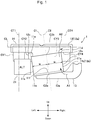
Fig. 3 is a front view of an internal combustion engine with an intercooler in a first comparative example. Theinternal combustion engine 101 with the intercooler in the first comparative example includes a liquid-cooledintercooler 111, anintake manifold 112, an intakeair passage member 113, and acylinder block 114. Theinternal combustion engine 101 with the intercooler also includes a first cylinder CY1, a second cylinder CY2, a third cylinder CY3, and a fourth cylinder CY4. In theinternal combustion engine 101 in the first comparative example, as arrangement of part of the elements is different from that of the present embodiment, the reference signs are different. However, functions of the respective elements are the same as those of the present embodiment. - As shown in
Fig. 3 , in a general internal combustion engine, as in theinternal combustion engine 101 in the first comparative example, the liquid-cooledintercooler 111 is arranged in such a manner that a cylinder bank direction center line C101 substantially matches a widthwise center line C102 of the liquid-cooled intercooler. In such a way, an intake allocation is not remarkably different between the cylinders. - In such an
internal combustion engine 101 with the intercooler in the first comparative example, there is a case where an auxiliary machine such as analternator 121 is intended to be arranged closer to the cylinder bank direction center line C101. However, when arranging in such a way, a contact portion D is generated between the liquid-cooledintercooler 111 and thealternator 121. Therefore, a need of arranging and displacing the liquid-cooledintercooler 111 arises. -
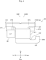
Fig. 4 is a front view of an internal combustion engine with an intercooler in a second comparative example. Theinternal combustion engine 201 with the intercooler in the second comparative example includes a liquid-cooledintercooler 211, anintake manifold 212, an intakeair passage member 213, and acylinder block 214. Theinternal combustion engine 201 with the intercooler also includes a first cylinder CY1, a second cylinder CY2, a third cylinder CY3, and a fourth cylinder CY4. In theinternal combustion engine 201 in the first comparative example, as arrangement of part of the elements is different from that of the present embodiment, the reference signs are different. However, functions of the respective elements are the same as those of the present embodiment. - In the above
internal combustion engine 101 with the intercooler in the first comparative example, thealternator 121 cannot be arranged at a desired position due to contact with the liquid-cooledintercooler 111. In theinternal combustion engine 201 with the intercooler in the second comparative example, in order to avoid contact with analternator 221, the liquid-cooledintercooler 211 is arranged in such a manner that a widthwise center line C202 of the liquid-cooledintercooler 211 is offset to the side of the fourth cylinder CY4 (the right side inFig. 4 ) from the cylinder bank direction center line C201. - When the liquid-cooled
intercooler 211 is simply moved in parallel to the right side as described above, because of connection with amanifold portion 212a, a sharp curve portion Cr1 is generated in a connection portion between the liquid-cooledintercooler 211 and themanifold portion 212a. In the intakeair passage member 213, there is a limitation that a position of a standingportion 213e thereof cannot be moved. Therefore, when the liquid-cooledintercooler 211 is simply moved in parallel to the right side as described above, a sharper curve portion Cr2 than the first comparative example is generated around a connection portion between the liquid-cooledintercooler 211 and the intakeair passage member 213. - In such a way, when the sharp curve portions Cr1, Cr2 are generated in the connection portions on the side of the fourth cylinder CY4, the air flowing in from the intake
air passage member 213 does not easily flow into the fourth cylinder CY4 due to an influence of inertia thereof. Since an amount of the air flowing into the fourth cylinder CY4 is remarkably reduced, the allocation of the inflow air is remarkably different between the cylinders. - Meanwhile, with the
internal combustion engine 1 in the present embodiment, no sharp curve portion is generated. Thus, the amount of the air flowing into the fourth cylinder CY4 is not remarkably reduced unlike the second comparative example. By doing so, in the present embodiment, the allocation of the inflow air can be not remarkably different between the cylinders. - Further, since the
internal combustion engine 1 in the present embodiment has the configuration as described above, the up-down length of the entire intake system piping structure of theinternal combustion engine 1 can be shortened. Then, a compactinternal combustion engine 1 can be provided. Thereby, there is an advantage that other auxiliary machine can be arranged or a working space can be provided on the lower side of the intakeair passage member 13 for example. - In the description of the above embodiment, the first cylinder CY1 corresponds to the end-side first cylinder and the fourth cylinder CY4 corresponds to the end-side fourth cylinder. However, the fourth cylinder CY4 may correspond to the end-side first cylinder and the first cylinder CY1 may correspond to the end-side fourth cylinder.
- In this case, the liquid-cooled
intercooler 11 is arranged in such a manner that the widthwise center C2b of the liquid-cooledintercooler 11 at the outlet of the liquid-cooledintercooler 11 is offset to the side of the first cylinder CY1 from the cylinder bank direction center line C1. The liquid-cooledintercooler 11 is arranged to be inclined in such a manner that the widthwise center C2a of the liquid-cooledintercooler 11 on the side of the inlet of the liquid-cooledintercooler 11 is placed closer to the side of the first cylinder CY1 than the widthwise center C2b of the liquid-cooledintercooler 11 on the side of the outlet of the liquid-cooledintercooler 11. The intakeair passage member 13 is connected to theconnection portion 11f of the liquid-cooledintercooler 11 from the side of the first cylinder CY1. - By doing so, a sharp curve portion is not generated in the flow passage of the air flowing into the first cylinder CY1. Thus, the allocation of the inflow air can be not remarkably different between the cylinders from the first cylinder CY1 to the fourth cylinder CY4.
- In the above embodiment, the inline four internal combustion engine is described as an example. However, as a matter of course, the number of cylinders may be more than this or less than this. Even in this case, the cylinders in both end portions of these cylinders correspond to the end-side first cylinder and the end-side second cylinder.
- In the above embodiment, the inline cylinder arrangement internal combustion engine is described as an example. However, not only in a case of the inline cylinder arrangement but also in a V cylinder arrangement internal combustion engine, the above embodiment can similarly be applied to one of two cylinder banks. For example, three cylinders are placed in line in a V-6 internal combustion engine, the cylinders in both end portions of the three cylinders correspond to the end-side first cylinder and the end-side second cylinder.
- In the above embodiment, the liquid-cooled
intercooler 11 is described as an example. However, the intercooler may be not the liquid-cooled intercooler but an air-cooled intercooler. - The embodiment of the present invention is described above. However, the above embodiment only shows part of application examples of the present invention and does not intend to limit the technical scope of the present invention to the specific configuration of the above embodiment.
Claims (5)
- An intake system piping structure of an internal combustion engine, comprising:an intake manifold connected to an end-side first cylinder and an end-side second cylinder which are provided farthest from each other in a cylinder bank in which a plurality of cylinders is placed in line; andan intercooler connected to the intake manifold, whereina widthwise center of the intercooler on the side of an intake inlet and a widthwise center of the intercooler on the side of the manifold are offset to the side of the end-side second cylinder from a cylinder bank direction center line in center between an axial center line of the end-side first cylinder and an axial center line of the end-side second cylinder, andthe intercooler is arranged in such a manner that an offset amount of the widthwise center of the intercooler on the side of the intake inlet from the cylinder bank direction center line is greater than an offset amount of the widthwise center of the intercooler on the side of the manifold from the cylinder bank direction center line.
- The intake system piping structure of the internal combustion engine according to claim 1, comprising:an intake air passage member connected from the side of the end-side second cylinder to the side of the intake inlet of the intercooler, whereina bottom portion of the intake air passage member is parallel to an orthogonal line orthogonal to the axial center line of the end-side first cylinder and the axial center line of the end-side second cylinder.
- The intake system piping structure of the internal combustion engine according to claim 2, wherein
in the intake air passage member, as more distant from the side of the end-side second cylinder and closer to the side of the end-side first cylinder, a distance from a connection portion between the intake air passage member and the intercooler to the bottom portion of the intake air passage member becomes shorter. - The intake system piping structure of the internal combustion engine according to claim 3, wherein
a lower end of the intercooler on the side of the end-side second cylinder matches an upper end of the intake air passage member, and
a lower end of the intercooler on the side of the end-side first cylinder is arranged on the lower side of the upper end of the intake air passage member. - The intake system piping structure of the internal combustion engine according to any one of claims 1 to 4, wherein
the intake manifold has a manifold portion and a branch portion, and
an upper end of the intercooler on the side of the end-side second cylinder matches a lower surface of the manifold portion, and
an upper end of the intercooler on the side of the end-side first cylinder is arranged on the lower side of the lower surface of the manifold portion.
Applications Claiming Priority (1)
| Application Number | Priority Date | Filing Date | Title |
|---|---|---|---|
| PCT/JP2015/055006 WO2016135820A1 (en) | 2015-02-23 | 2015-02-23 | Intake system piping structure for internal combustion engine |
Publications (2)
| Publication Number | Publication Date |
|---|---|
| EP3263863A1 true EP3263863A1 (en) | 2018-01-03 |
| EP3263863A4 EP3263863A4 (en) | 2018-01-24 |
Family
ID=56788074
Family Applications (1)
| Application Number | Title | Priority Date | Filing Date |
|---|---|---|---|
| EP15883118.0A Withdrawn EP3263863A4 (en) | 2015-02-23 | 2015-02-23 | Intake system piping structure for internal combustion engine |
Country Status (9)
| Country | Link |
|---|---|
| US (1) | US10655575B2 (en) |
| EP (1) | EP3263863A4 (en) |
| JP (1) | JP6409952B2 (en) |
| KR (1) | KR101851917B1 (en) |
| CN (1) | CN107250502B (en) |
| CA (1) | CA2977335C (en) |
| MX (1) | MX379113B (en) |
| RU (1) | RU2652263C1 (en) |
| WO (1) | WO2016135820A1 (en) |
Families Citing this family (2)
| Publication number | Priority date | Publication date | Assignee | Title |
|---|---|---|---|---|
| CN114008312B (en) * | 2019-06-21 | 2023-12-26 | 日产自动车株式会社 | heat exchange device |
| DE102019121494A1 (en) * | 2019-08-09 | 2021-02-11 | Mann+Hummel Gmbh | Heat exchanger arrangement, method for producing a heat exchanger arrangement and internal combustion engine with heat exchanger arrangement |
Family Cites Families (19)
| Publication number | Priority date | Publication date | Assignee | Title |
|---|---|---|---|---|
| US2013157A (en) * | 1931-07-06 | 1935-09-03 | Continental Motors Corp | Engine |
| DE1061129B (en) * | 1954-04-30 | 1959-07-09 | Maschf Augsburg Nuernberg Ag | Internal combustion engine with an in-line arrangement of the cylinders |
| JPH01102434U (en) * | 1987-12-25 | 1989-07-11 | ||
| JP2676252B2 (en) * | 1989-04-18 | 1997-11-12 | ヤンマーディーゼル株式会社 | Multi-cylinder engine |
| JPH0565826A (en) * | 1991-09-05 | 1993-03-19 | Toyota Motor Corp | Air suction device of internal combustion engine |
| FI116802B (en) * | 2002-01-17 | 2006-02-28 | Waertsilae Finland Oy | Suction air arrangement for piston engine |
| JP2007224786A (en) | 2006-02-22 | 2007-09-06 | Komatsu Ltd | Exhaust gas recirculation device |
| FR2908833B1 (en) * | 2006-11-20 | 2011-06-17 | Valeo Sys Controle Moteur Sas | GAS ADMISSION DEVICE |
| JP2009270508A (en) | 2008-05-08 | 2009-11-19 | Toyota Motor Corp | Internal combustion engine with intercooler |
| FR2954414B1 (en) * | 2009-12-21 | 2013-09-13 | Valeo Systemes Thermiques | INTERFACE PIECE BETWEEN A CYLINDER HEAD OF A MOTOR VEHICLE ENGINE AND A HEAT EXCHANGER. |
| DE102010002233A1 (en) * | 2010-02-23 | 2011-08-25 | Behr GmbH & Co. KG, 70469 | Device for exhaust gas recirculation for an internal combustion engine |
| JP2012092674A (en) * | 2010-10-25 | 2012-05-17 | Denso Corp | Intercooler |
| US8443603B2 (en) * | 2011-05-10 | 2013-05-21 | GM Global Technology Operations LLC | Intake manifold assembly for dedicated exhaust gas recirculation |
| JP2013011175A (en) * | 2011-06-28 | 2013-01-17 | Mahle Filter Systems Japan Corp | Seal structure of intake manifold |
| US9145858B2 (en) * | 2012-02-29 | 2015-09-29 | Ford Global Technologies, Llc | Intake system with an integrated charge air cooler |
| DE102012017391A1 (en) * | 2012-09-01 | 2014-05-15 | Volkswagen Aktiengesellschaft | Suction tube for an internal combustion engine |
| US9038610B2 (en) * | 2013-02-18 | 2015-05-26 | Modine Manufacturing Company | Charge air cooler, and intake manifold including the same |
| DE102013006955A1 (en) * | 2013-04-23 | 2014-10-23 | Modine Manufacturing Co. | Intake manifold with a charge air cooler |
| KR20150075421A (en) * | 2013-12-17 | 2015-07-06 | 현대자동차주식회사 | Engine system having turbo charger |
-
2015
- 2015-02-23 JP JP2017501571A patent/JP6409952B2/en not_active Expired - Fee Related
- 2015-02-23 KR KR1020177023509A patent/KR101851917B1/en not_active Expired - Fee Related
- 2015-02-23 MX MX2017010454A patent/MX379113B/en unknown
- 2015-02-23 EP EP15883118.0A patent/EP3263863A4/en not_active Withdrawn
- 2015-02-23 WO PCT/JP2015/055006 patent/WO2016135820A1/en not_active Ceased
- 2015-02-23 RU RU2017129811A patent/RU2652263C1/en active
- 2015-02-23 CN CN201580076697.3A patent/CN107250502B/en not_active Expired - Fee Related
- 2015-02-23 CA CA2977335A patent/CA2977335C/en active Active
- 2015-02-23 US US15/552,638 patent/US10655575B2/en not_active Expired - Fee Related
Also Published As
| Publication number | Publication date |
|---|---|
| EP3263863A4 (en) | 2018-01-24 |
| US10655575B2 (en) | 2020-05-19 |
| CN107250502B (en) | 2020-04-14 |
| MX379113B (en) | 2025-03-11 |
| KR20170102027A (en) | 2017-09-06 |
| KR101851917B1 (en) | 2018-06-07 |
| MX2017010454A (en) | 2017-11-28 |
| CN107250502A (en) | 2017-10-13 |
| CA2977335A1 (en) | 2016-09-01 |
| CA2977335C (en) | 2018-01-02 |
| JP6409952B2 (en) | 2018-10-24 |
| JPWO2016135820A1 (en) | 2017-11-30 |
| RU2652263C1 (en) | 2018-04-25 |
| WO2016135820A1 (en) | 2016-09-01 |
| US20180017026A1 (en) | 2018-01-18 |
Similar Documents
| Publication | Publication Date | Title |
|---|---|---|
| US9243547B2 (en) | Dual inlet and outlet exhaust gas recirculation cooler for turbocharged engine | |
| US20140360704A1 (en) | Radiator for vehicle | |
| US9618282B2 (en) | Radiator for vehicle | |
| CN104428524B (en) | intake manifold | |
| US8739756B2 (en) | Engine assembly with engine block-integrated cooling system | |
| KR20130037981A (en) | Exhaust port structure of cylinder head | |
| KR101868111B1 (en) | Carrier housing and internal combustion engine | |
| US10954883B2 (en) | Water jacket structure | |
| US20160281583A1 (en) | Cylinder block of internal combustion engine | |
| CA2977335C (en) | Intake system piping structure of internal combustion engine | |
| US20130192546A1 (en) | Coolant Jacket for a Liquid-Cooled Cylinder Head | |
| US20210123398A1 (en) | Air Intake Apparatus | |
| JP6459498B2 (en) | Engine intake structure | |
| CN105443236A (en) | A turbocharged engine and a method of making the same | |
| US20160153393A1 (en) | Aluminum monoblock engine using interbore concentration flux supply type water jacket | |
| JP4760526B2 (en) | Cylinder head of internal combustion engine | |
| US20180209327A1 (en) | Exhaust gas supply arrangement of an exhaust gas turbocharger | |
| KR102031233B1 (en) | Exhaust-gas turbocharger | |
| JP6057703B2 (en) | Flow path | |
| JP2009275575A (en) | Cooling device for internal combustion engine | |
| JP6424759B2 (en) | Arrangement structure of hose and wire harness in cylinder head cover of internal combustion engine and cylinder head cover of internal combustion engine | |
| KR101199170B1 (en) | Exhaust United type Cylinder Head | |
| EP3381729B1 (en) | Engine mounting structure | |
| JP5146195B2 (en) | V-type internal combustion engine cooling device and V-type internal combustion engine | |
| US9694670B2 (en) | Under cover for heat suction |
Legal Events
| Date | Code | Title | Description |
|---|---|---|---|
| PUAI | Public reference made under article 153(3) epc to a published international application that has entered the european phase |
Free format text: ORIGINAL CODE: 0009012 |
|
| 17P | Request for examination filed |
Effective date: 20170905 |
|
| AK | Designated contracting states |
Kind code of ref document: A1 Designated state(s): AL AT BE BG CH CY CZ DE DK EE ES FI FR GB GR HR HU IE IS IT LI LT LU LV MC MK MT NL NO PL PT RO RS SE SI SK SM TR |
|
| AX | Request for extension of the european patent |
Extension state: BA ME |
|
| A4 | Supplementary search report drawn up and despatched |
Effective date: 20171221 |
|
| RIC1 | Information provided on ipc code assigned before grant |
Ipc: F02M 35/104 20060101ALI20171215BHEP Ipc: F02M 35/112 20060101ALI20171215BHEP Ipc: F02B 29/04 20060101AFI20171215BHEP |
|
| DAX | Request for extension of the european patent (deleted) | ||
| 17Q | First examination report despatched |
Effective date: 20180703 |
|
| STAA | Information on the status of an ep patent application or granted ep patent |
Free format text: STATUS: THE APPLICATION IS DEEMED TO BE WITHDRAWN |
|
| 18D | Application deemed to be withdrawn |
Effective date: 20190515 |