EP3263861B1 - Heating structure, production method therefor, and pump module comprising same - Google Patents
Heating structure, production method therefor, and pump module comprising same Download PDFInfo
- Publication number
- EP3263861B1 EP3263861B1 EP16755865.9A EP16755865A EP3263861B1 EP 3263861 B1 EP3263861 B1 EP 3263861B1 EP 16755865 A EP16755865 A EP 16755865A EP 3263861 B1 EP3263861 B1 EP 3263861B1
- Authority
- EP
- European Patent Office
- Prior art keywords
- discharge tube
- pump
- flange
- pump module
- groove
- Prior art date
- Legal status (The legal status is an assumption and is not a legal conclusion. Google has not performed a legal analysis and makes no representation as to the accuracy of the status listed.)
- Active
Links
Images



Classifications
-
- F—MECHANICAL ENGINEERING; LIGHTING; HEATING; WEAPONS; BLASTING
- F01—MACHINES OR ENGINES IN GENERAL; ENGINE PLANTS IN GENERAL; STEAM ENGINES
- F01N—GAS-FLOW SILENCERS OR EXHAUST APPARATUS FOR MACHINES OR ENGINES IN GENERAL; GAS-FLOW SILENCERS OR EXHAUST APPARATUS FOR INTERNAL-COMBUSTION ENGINES
- F01N3/00—Exhaust or silencing apparatus having means for purifying, rendering innocuous, or otherwise treating exhaust
- F01N3/08—Exhaust or silencing apparatus having means for purifying, rendering innocuous, or otherwise treating exhaust for rendering innocuous
- F01N3/10—Exhaust or silencing apparatus having means for purifying, rendering innocuous, or otherwise treating exhaust for rendering innocuous by thermal or catalytic conversion of noxious components of exhaust
- F01N3/18—Exhaust or silencing apparatus having means for purifying, rendering innocuous, or otherwise treating exhaust for rendering innocuous by thermal or catalytic conversion of noxious components of exhaust characterised by methods of operation; Control
- F01N3/20—Exhaust or silencing apparatus having means for purifying, rendering innocuous, or otherwise treating exhaust for rendering innocuous by thermal or catalytic conversion of noxious components of exhaust characterised by methods of operation; Control specially adapted for catalytic conversion
- F01N3/206—Adding periodically or continuously substances to exhaust gases for promoting purification, e.g. catalytic material in liquid form, NOx reducing agents
- F01N3/2066—Selective catalytic reduction [SCR]
- F01N3/2073—Means for generating a reducing substance from the exhaust gases
-
- F—MECHANICAL ENGINEERING; LIGHTING; HEATING; WEAPONS; BLASTING
- F01—MACHINES OR ENGINES IN GENERAL; ENGINE PLANTS IN GENERAL; STEAM ENGINES
- F01N—GAS-FLOW SILENCERS OR EXHAUST APPARATUS FOR MACHINES OR ENGINES IN GENERAL; GAS-FLOW SILENCERS OR EXHAUST APPARATUS FOR INTERNAL-COMBUSTION ENGINES
- F01N3/00—Exhaust or silencing apparatus having means for purifying, rendering innocuous, or otherwise treating exhaust
- F01N3/08—Exhaust or silencing apparatus having means for purifying, rendering innocuous, or otherwise treating exhaust for rendering innocuous
- F01N3/10—Exhaust or silencing apparatus having means for purifying, rendering innocuous, or otherwise treating exhaust for rendering innocuous by thermal or catalytic conversion of noxious components of exhaust
- F01N3/18—Exhaust or silencing apparatus having means for purifying, rendering innocuous, or otherwise treating exhaust for rendering innocuous by thermal or catalytic conversion of noxious components of exhaust characterised by methods of operation; Control
- F01N3/20—Exhaust or silencing apparatus having means for purifying, rendering innocuous, or otherwise treating exhaust for rendering innocuous by thermal or catalytic conversion of noxious components of exhaust characterised by methods of operation; Control specially adapted for catalytic conversion
- F01N3/206—Adding periodically or continuously substances to exhaust gases for promoting purification, e.g. catalytic material in liquid form, NOx reducing agents
- F01N3/208—Control of selective catalytic reduction [SCR], e.g. by adjusting the dosing of reducing agent
-
- B—PERFORMING OPERATIONS; TRANSPORTING
- B60—VEHICLES IN GENERAL
- B60K—ARRANGEMENT OR MOUNTING OF PROPULSION UNITS OR OF TRANSMISSIONS IN VEHICLES; ARRANGEMENT OR MOUNTING OF PLURAL DIVERSE PRIME-MOVERS IN VEHICLES; AUXILIARY DRIVES FOR VEHICLES; INSTRUMENTATION OR DASHBOARDS FOR VEHICLES; ARRANGEMENTS IN CONNECTION WITH COOLING, AIR INTAKE, GAS EXHAUST OR FUEL SUPPLY OF PROPULSION UNITS IN VEHICLES
- B60K13/00—Arrangement in connection with combustion air intake or gas exhaust of propulsion units
- B60K13/04—Arrangement in connection with combustion air intake or gas exhaust of propulsion units concerning exhaust
-
- B—PERFORMING OPERATIONS; TRANSPORTING
- B60—VEHICLES IN GENERAL
- B60K—ARRANGEMENT OR MOUNTING OF PROPULSION UNITS OR OF TRANSMISSIONS IN VEHICLES; ARRANGEMENT OR MOUNTING OF PLURAL DIVERSE PRIME-MOVERS IN VEHICLES; AUXILIARY DRIVES FOR VEHICLES; INSTRUMENTATION OR DASHBOARDS FOR VEHICLES; ARRANGEMENTS IN CONNECTION WITH COOLING, AIR INTAKE, GAS EXHAUST OR FUEL SUPPLY OF PROPULSION UNITS IN VEHICLES
- B60K15/00—Arrangement in connection with fuel supply of combustion engines or other fuel consuming energy converters, e.g. fuel cells; Mounting or construction of fuel tanks
- B60K15/03—Fuel tanks
-
- F—MECHANICAL ENGINEERING; LIGHTING; HEATING; WEAPONS; BLASTING
- F01—MACHINES OR ENGINES IN GENERAL; ENGINE PLANTS IN GENERAL; STEAM ENGINES
- F01N—GAS-FLOW SILENCERS OR EXHAUST APPARATUS FOR MACHINES OR ENGINES IN GENERAL; GAS-FLOW SILENCERS OR EXHAUST APPARATUS FOR INTERNAL-COMBUSTION ENGINES
- F01N3/00—Exhaust or silencing apparatus having means for purifying, rendering innocuous, or otherwise treating exhaust
- F01N3/08—Exhaust or silencing apparatus having means for purifying, rendering innocuous, or otherwise treating exhaust for rendering innocuous
- F01N3/10—Exhaust or silencing apparatus having means for purifying, rendering innocuous, or otherwise treating exhaust for rendering innocuous by thermal or catalytic conversion of noxious components of exhaust
- F01N3/18—Exhaust or silencing apparatus having means for purifying, rendering innocuous, or otherwise treating exhaust for rendering innocuous by thermal or catalytic conversion of noxious components of exhaust characterised by methods of operation; Control
- F01N3/20—Exhaust or silencing apparatus having means for purifying, rendering innocuous, or otherwise treating exhaust for rendering innocuous by thermal or catalytic conversion of noxious components of exhaust characterised by methods of operation; Control specially adapted for catalytic conversion
- F01N3/2006—Periodically heating or cooling catalytic reactors, e.g. at cold starting or overheating
- F01N3/2013—Periodically heating or cooling catalytic reactors, e.g. at cold starting or overheating using electric or magnetic heating means
-
- F—MECHANICAL ENGINEERING; LIGHTING; HEATING; WEAPONS; BLASTING
- F01—MACHINES OR ENGINES IN GENERAL; ENGINE PLANTS IN GENERAL; STEAM ENGINES
- F01N—GAS-FLOW SILENCERS OR EXHAUST APPARATUS FOR MACHINES OR ENGINES IN GENERAL; GAS-FLOW SILENCERS OR EXHAUST APPARATUS FOR INTERNAL-COMBUSTION ENGINES
- F01N3/00—Exhaust or silencing apparatus having means for purifying, rendering innocuous, or otherwise treating exhaust
- F01N3/08—Exhaust or silencing apparatus having means for purifying, rendering innocuous, or otherwise treating exhaust for rendering innocuous
- F01N3/10—Exhaust or silencing apparatus having means for purifying, rendering innocuous, or otherwise treating exhaust for rendering innocuous by thermal or catalytic conversion of noxious components of exhaust
- F01N3/24—Exhaust or silencing apparatus having means for purifying, rendering innocuous, or otherwise treating exhaust for rendering innocuous by thermal or catalytic conversion of noxious components of exhaust characterised by constructional aspects of converting apparatus
- F01N3/28—Construction of catalytic reactors
- F01N3/2896—Liquid catalyst carrier
-
- H—ELECTRICITY
- H05—ELECTRIC TECHNIQUES NOT OTHERWISE PROVIDED FOR
- H05B—ELECTRIC HEATING; ELECTRIC LIGHT SOURCES NOT OTHERWISE PROVIDED FOR; CIRCUIT ARRANGEMENTS FOR ELECTRIC LIGHT SOURCES, IN GENERAL
- H05B3/00—Ohmic-resistance heating
- H05B3/10—Heating elements characterised by the composition or nature of the materials or by the arrangement of the conductor
- H05B3/12—Heating elements characterised by the composition or nature of the materials or by the arrangement of the conductor characterised by the composition or nature of the conductive material
-
- H—ELECTRICITY
- H05—ELECTRIC TECHNIQUES NOT OTHERWISE PROVIDED FOR
- H05B—ELECTRIC HEATING; ELECTRIC LIGHT SOURCES NOT OTHERWISE PROVIDED FOR; CIRCUIT ARRANGEMENTS FOR ELECTRIC LIGHT SOURCES, IN GENERAL
- H05B3/00—Ohmic-resistance heating
- H05B3/78—Heating arrangements specially adapted for immersion heating
-
- B—PERFORMING OPERATIONS; TRANSPORTING
- B60—VEHICLES IN GENERAL
- B60K—ARRANGEMENT OR MOUNTING OF PROPULSION UNITS OR OF TRANSMISSIONS IN VEHICLES; ARRANGEMENT OR MOUNTING OF PLURAL DIVERSE PRIME-MOVERS IN VEHICLES; AUXILIARY DRIVES FOR VEHICLES; INSTRUMENTATION OR DASHBOARDS FOR VEHICLES; ARRANGEMENTS IN CONNECTION WITH COOLING, AIR INTAKE, GAS EXHAUST OR FUEL SUPPLY OF PROPULSION UNITS IN VEHICLES
- B60K15/00—Arrangement in connection with fuel supply of combustion engines or other fuel consuming energy converters, e.g. fuel cells; Mounting or construction of fuel tanks
- B60K15/03—Fuel tanks
- B60K2015/03328—Arrangements or special measures related to fuel tanks or fuel handling
- B60K2015/03427—Arrangements or special measures related to fuel tanks or fuel handling for heating fuel, e.g. to avoiding freezing
-
- F—MECHANICAL ENGINEERING; LIGHTING; HEATING; WEAPONS; BLASTING
- F01—MACHINES OR ENGINES IN GENERAL; ENGINE PLANTS IN GENERAL; STEAM ENGINES
- F01N—GAS-FLOW SILENCERS OR EXHAUST APPARATUS FOR MACHINES OR ENGINES IN GENERAL; GAS-FLOW SILENCERS OR EXHAUST APPARATUS FOR INTERNAL-COMBUSTION ENGINES
- F01N2240/00—Combination or association of two or more different exhaust treating devices, or of at least one such device with an auxiliary device, not covered by indexing codes F01N2230/00 or F01N2250/00, one of the devices being
- F01N2240/16—Combination or association of two or more different exhaust treating devices, or of at least one such device with an auxiliary device, not covered by indexing codes F01N2230/00 or F01N2250/00, one of the devices being an electric heater, i.e. a resistance heater
-
- F—MECHANICAL ENGINEERING; LIGHTING; HEATING; WEAPONS; BLASTING
- F01—MACHINES OR ENGINES IN GENERAL; ENGINE PLANTS IN GENERAL; STEAM ENGINES
- F01N—GAS-FLOW SILENCERS OR EXHAUST APPARATUS FOR MACHINES OR ENGINES IN GENERAL; GAS-FLOW SILENCERS OR EXHAUST APPARATUS FOR INTERNAL-COMBUSTION ENGINES
- F01N2610/00—Adding substances to exhaust gases
- F01N2610/02—Adding substances to exhaust gases the substance being ammonia or urea
-
- F—MECHANICAL ENGINEERING; LIGHTING; HEATING; WEAPONS; BLASTING
- F01—MACHINES OR ENGINES IN GENERAL; ENGINE PLANTS IN GENERAL; STEAM ENGINES
- F01N—GAS-FLOW SILENCERS OR EXHAUST APPARATUS FOR MACHINES OR ENGINES IN GENERAL; GAS-FLOW SILENCERS OR EXHAUST APPARATUS FOR INTERNAL-COMBUSTION ENGINES
- F01N2610/00—Adding substances to exhaust gases
- F01N2610/10—Adding substances to exhaust gases the substance being heated, e.g. by heating tank or supply line of the added substance
-
- F—MECHANICAL ENGINEERING; LIGHTING; HEATING; WEAPONS; BLASTING
- F01—MACHINES OR ENGINES IN GENERAL; ENGINE PLANTS IN GENERAL; STEAM ENGINES
- F01N—GAS-FLOW SILENCERS OR EXHAUST APPARATUS FOR MACHINES OR ENGINES IN GENERAL; GAS-FLOW SILENCERS OR EXHAUST APPARATUS FOR INTERNAL-COMBUSTION ENGINES
- F01N2610/00—Adding substances to exhaust gases
- F01N2610/14—Arrangements for the supply of substances, e.g. conduits
- F01N2610/1406—Storage means for substances, e.g. tanks or reservoirs
-
- F—MECHANICAL ENGINEERING; LIGHTING; HEATING; WEAPONS; BLASTING
- F01—MACHINES OR ENGINES IN GENERAL; ENGINE PLANTS IN GENERAL; STEAM ENGINES
- F01N—GAS-FLOW SILENCERS OR EXHAUST APPARATUS FOR MACHINES OR ENGINES IN GENERAL; GAS-FLOW SILENCERS OR EXHAUST APPARATUS FOR INTERNAL-COMBUSTION ENGINES
- F01N2610/00—Adding substances to exhaust gases
- F01N2610/14—Arrangements for the supply of substances, e.g. conduits
- F01N2610/1426—Filtration means
-
- F—MECHANICAL ENGINEERING; LIGHTING; HEATING; WEAPONS; BLASTING
- F01—MACHINES OR ENGINES IN GENERAL; ENGINE PLANTS IN GENERAL; STEAM ENGINES
- F01N—GAS-FLOW SILENCERS OR EXHAUST APPARATUS FOR MACHINES OR ENGINES IN GENERAL; GAS-FLOW SILENCERS OR EXHAUST APPARATUS FOR INTERNAL-COMBUSTION ENGINES
- F01N2610/00—Adding substances to exhaust gases
- F01N2610/14—Arrangements for the supply of substances, e.g. conduits
- F01N2610/1433—Pumps
-
- F—MECHANICAL ENGINEERING; LIGHTING; HEATING; WEAPONS; BLASTING
- F01—MACHINES OR ENGINES IN GENERAL; ENGINE PLANTS IN GENERAL; STEAM ENGINES
- F01N—GAS-FLOW SILENCERS OR EXHAUST APPARATUS FOR MACHINES OR ENGINES IN GENERAL; GAS-FLOW SILENCERS OR EXHAUST APPARATUS FOR INTERNAL-COMBUSTION ENGINES
- F01N2610/00—Adding substances to exhaust gases
- F01N2610/14—Arrangements for the supply of substances, e.g. conduits
- F01N2610/1486—Means to prevent the substance from freezing
-
- F—MECHANICAL ENGINEERING; LIGHTING; HEATING; WEAPONS; BLASTING
- F01—MACHINES OR ENGINES IN GENERAL; ENGINE PLANTS IN GENERAL; STEAM ENGINES
- F01N—GAS-FLOW SILENCERS OR EXHAUST APPARATUS FOR MACHINES OR ENGINES IN GENERAL; GAS-FLOW SILENCERS OR EXHAUST APPARATUS FOR INTERNAL-COMBUSTION ENGINES
- F01N2900/00—Details of electrical control or of the monitoring of the exhaust gas treating apparatus
- F01N2900/06—Parameters used for exhaust control or diagnosing
- F01N2900/18—Parameters used for exhaust control or diagnosing said parameters being related to the system for adding a substance into the exhaust
- F01N2900/1806—Properties of reducing agent or dosing system
- F01N2900/1808—Pressure
-
- F—MECHANICAL ENGINEERING; LIGHTING; HEATING; WEAPONS; BLASTING
- F01—MACHINES OR ENGINES IN GENERAL; ENGINE PLANTS IN GENERAL; STEAM ENGINES
- F01N—GAS-FLOW SILENCERS OR EXHAUST APPARATUS FOR MACHINES OR ENGINES IN GENERAL; GAS-FLOW SILENCERS OR EXHAUST APPARATUS FOR INTERNAL-COMBUSTION ENGINES
- F01N2900/00—Details of electrical control or of the monitoring of the exhaust gas treating apparatus
- F01N2900/06—Parameters used for exhaust control or diagnosing
- F01N2900/18—Parameters used for exhaust control or diagnosing said parameters being related to the system for adding a substance into the exhaust
- F01N2900/1806—Properties of reducing agent or dosing system
- F01N2900/1811—Temperature
-
- F—MECHANICAL ENGINEERING; LIGHTING; HEATING; WEAPONS; BLASTING
- F01—MACHINES OR ENGINES IN GENERAL; ENGINE PLANTS IN GENERAL; STEAM ENGINES
- F01N—GAS-FLOW SILENCERS OR EXHAUST APPARATUS FOR MACHINES OR ENGINES IN GENERAL; GAS-FLOW SILENCERS OR EXHAUST APPARATUS FOR INTERNAL-COMBUSTION ENGINES
- F01N3/00—Exhaust or silencing apparatus having means for purifying, rendering innocuous, or otherwise treating exhaust
- F01N3/08—Exhaust or silencing apparatus having means for purifying, rendering innocuous, or otherwise treating exhaust for rendering innocuous
- F01N3/10—Exhaust or silencing apparatus having means for purifying, rendering innocuous, or otherwise treating exhaust for rendering innocuous by thermal or catalytic conversion of noxious components of exhaust
- F01N3/18—Exhaust or silencing apparatus having means for purifying, rendering innocuous, or otherwise treating exhaust for rendering innocuous by thermal or catalytic conversion of noxious components of exhaust characterised by methods of operation; Control
- F01N3/20—Exhaust or silencing apparatus having means for purifying, rendering innocuous, or otherwise treating exhaust for rendering innocuous by thermal or catalytic conversion of noxious components of exhaust characterised by methods of operation; Control specially adapted for catalytic conversion
- F01N3/206—Adding periodically or continuously substances to exhaust gases for promoting purification, e.g. catalytic material in liquid form, NOx reducing agents
- F01N3/2066—Selective catalytic reduction [SCR]
-
- Y—GENERAL TAGGING OF NEW TECHNOLOGICAL DEVELOPMENTS; GENERAL TAGGING OF CROSS-SECTIONAL TECHNOLOGIES SPANNING OVER SEVERAL SECTIONS OF THE IPC; TECHNICAL SUBJECTS COVERED BY FORMER USPC CROSS-REFERENCE ART COLLECTIONS [XRACs] AND DIGESTS
- Y02—TECHNOLOGIES OR APPLICATIONS FOR MITIGATION OR ADAPTATION AGAINST CLIMATE CHANGE
- Y02A—TECHNOLOGIES FOR ADAPTATION TO CLIMATE CHANGE
- Y02A50/00—TECHNOLOGIES FOR ADAPTATION TO CLIMATE CHANGE in human health protection, e.g. against extreme weather
- Y02A50/20—Air quality improvement or preservation, e.g. vehicle emission control or emission reduction by using catalytic converters
-
- Y—GENERAL TAGGING OF NEW TECHNOLOGICAL DEVELOPMENTS; GENERAL TAGGING OF CROSS-SECTIONAL TECHNOLOGIES SPANNING OVER SEVERAL SECTIONS OF THE IPC; TECHNICAL SUBJECTS COVERED BY FORMER USPC CROSS-REFERENCE ART COLLECTIONS [XRACs] AND DIGESTS
- Y02—TECHNOLOGIES OR APPLICATIONS FOR MITIGATION OR ADAPTATION AGAINST CLIMATE CHANGE
- Y02T—CLIMATE CHANGE MITIGATION TECHNOLOGIES RELATED TO TRANSPORTATION
- Y02T10/00—Road transport of goods or passengers
- Y02T10/10—Internal combustion engine [ICE] based vehicles
- Y02T10/12—Improving ICE efficiencies
Definitions
- the present invention relates to a heating structure, a production method therefor, and a pump module including the same.
- an exhaust system for a diesel engine includes an exhaust gas post-processing unit, such as a selective catalyst reduction (SCR) unit, a diesel oxidation catalyst (DOC) unit, a catalyzed particulate filter (CPF), so as to reduce a nitrogen oxide (NOx) contained in exhaust gas.
- SCR selective catalyst reduction
- DOC diesel oxidation catalyst
- CPF catalyzed particulate filter
- an exhaust gas post-processing unit that applies SCR performs a function of injecting a reductant, such as an aqueous urea solution, into an inside of an exhaust pipe to reduce NOx in the exhaust gas into nitrogen and oxygen.
- a reductant such as an aqueous urea solution
- the reductant when the reductant is injected into the inside of the exhaust pipe, the reductant can be changed to ammonia (NH 3 ) by heat of the exhaust gas, and NOx can be reduced into nitrogen gas (N 2 ) and water (H 2 O) as a catalyst reaction of NOx in the exhaust gas and ammonia using an SCR catalyst.
- NH 3 ammonia
- NOx nitrogen gas
- H 2 O water
- a system for supplying the aqueous urea solution to the SCR unit is required to inject the aqueous urea solution into the inside of the exhaust pipe using the SCR unit.
- the system for supplying the aqueous urea solution basically includes a urea tank for storing the aqueous urea solution and a pump module that is disposed in the urea tank and supplies the aqueous urea solution to the SCR unit.
- a heating device and a pump are installed to be spaced by a predetermined distance apart from each other.
- EP2837785 discloses a pump unit and EP2299079 discloses a cartridge having a filter device filtering liquid.
- the present invention is directed to providing a heating structure for stably pumping a strongly alkaline aqueous urea solution using an injector and melting the frozen aqueous urea solution in the winter season, a production method therefor, and a pump module including the same.
- One aspect of the present invention provides a heating structure, which is for heating a pump installed in a tank so as to discharge a liquid stored in the tank to the outside of the tank, including: a flange installed on one surface of the interior of the tank; and a heating member coupled to one surface of the flange and provided on one side thereof with an accommodation groove in which at least a part of the pump is accommodated, wherein a first discharge tube of the pump having at least a part thereof accommodated in the accommodation groove extends toward the flange and is connected to a second discharge tube formed on the other surface of the flange outside the tank, and the heating member is formed to heat at least a part of the pump, at least a part of the first discharge tube, and at least a part of the second discharge tube.
- the heating member may include: a body that extends in an inward direction of the tank; and a positive temperature coefficient (PTC) device coupled to an outside surface of the body, and the accommodation groove may be formed in an end that opens in the inward direction of the tank of the body.
- PTC positive temperature coefficient
- the heating structure may further include a cover coupled to the body so as to cover and seal the PTC device.
- a protrusion may be formed on one side of the PTC device and may protrude toward the flange, and a plug connected to the PTC device may be formed on an end of the protrusion, and a first groove may be recessed in the one surface of the flange so that the protrusion is inserted into the first groove, and a socket corresponding to the plug may be formed in a center of the first groove.
- the heating structure may further include a first sealing member formed on an outer circumferential surface of the protrusion.
- the heating structure may further include: a mounting groove formed in one side surface of the body so that the PTC device is inserted into the body through the mounting groove; and a wall portion formed at a circumference of the mounting groove, wherein the cover may be coupled to the wall portion to cover and seal the PTC device and to fix the PTC device to the body.
- the heating structure may further include a gasket disposed between the wall portion and the cover and sealing a space between the wall portion and the cover.
- the heating structure may further include a power cutoff unit that cuts off power supplied to the PTC device when the power cutoff unit is electrically connected to the PTC device and the PTC device is at a Curie temperature or higher.
- the heating structure may further include a temperature sensor that is installed on one surface of the flange and detects a temperature of the liquid.
- a second groove may be formed in one surface of the flange to accommodate at least a part of the first discharge tube, and one end of the body capable of heating at least a part of the first discharge tube may be accommodated in the second groove together with at least a part of the first discharge tube.
- One end of the body may be formed to heat a part of the second discharge tube.
- a connection tube may be formed in the second groove of the flange, may protrude from an interior of the second groove of the flange, may extend toward the heating member and may connect the first discharge tube to the second discharge tube.
- the heating structure may further include a linear discharge tube coupled to the first discharge tube, wherein the discharge tube may be disposed in the connection tube while being coupled to the first discharge tube.
- the heating structure may further include a second sealing member formed at an outer circumferential surface of the discharge tube so as to seal a space between the discharge tube and the connection tube.
- the tank may be a storage tank for storing an aqueous urea solution.
- the pump module includes a pump installable in a storage tank so as to discharge a liquid stored in the storage tank to an outside of the storage tank; the above-described heating structure disposed to surround an outside surface of the pump; a coupling member coupled to an outside of the pump so as to couple the heating structure to the flange; and a filter coupled to the flange to surround the pump, the coupling member and the heating structure and filtering the liquid supplied to the pump.
- a production method for a heating structure including: providing a body having a mounting groove formed in one side surface thereof and a wall portion provided at a circumference of the mounting groove; inserting a positive temperature coefficient (PTC) device into the mounting groove; installing a gasket at the wall portion and coupling a cover to the wall portion; and injection molding a surface of the body to which the cover is coupled, to form a housing.
- PTC positive temperature coefficient
- a frozen aqueous urea solution can be melted using a positive temperature coefficient (PTC) device capable of heating the aqueous urea solution, and damage caused by electrical overload can be prevented.
- PTC positive temperature coefficient
- a strongly alkaline aqueous urea solution can be stably pumped using an injector.
- a flange mounted on a lower portion of a tank is provided so that installation of the heating structure in the pump module is simple.
- a body is formed to heat a part of a first discharge tube and a part of a second discharge tube so that the frozen aqueous urea solution that is present in the discharge tube of the pump module can be efficiently melted.
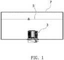
- FIG. 1 is a perspective view showing a state in which a pump module having a heating structure mounted thereon according to an embodiment of the present invention is installed in a tank.
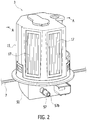
- FIG. 2 is a perspective view of the pump module having the heating structure mounted thereon according to an embodiment of the present invention.
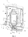
- FIG. 3 is a cross-sectional view taken along a line A-A of FIG. 2 , wherein arrows represent a flow of a liquid.
- a pump module 3 having a heating structure 1 mounted thereon may include a pump 9, the heating structure 1, a coupling member 13, and a filter 15.
- the pump module 3 may be installed in a tank 7 in which a liquid is stored, and may pump the liquid using an injector (not shown) installed outside the tank stably.
- the pump module 3 may perform a function of adjusting the temperature and level of the liquid stored in the tank 7 and filtering the liquid stored in the tank 7 and may melt the frozen liquid using the heating structure 1 installed therein. This enables the frozen liquid to be firstly melted before the pump 9 operates, so that the pump can operate smoothly.
- the liquid stored in the storage tank 7 may be an aqueous urea solution 5 used as a reductant.
- the aqueous urea solution 5 is colorless, odorless, nonpoisonous, unburnable, and strongly alkaline (PH 10 or higher) and is mixed in water at the ratio of 32.5%.
- a freezing point of the aqueous urea solution 5 that is strongly alkaline is -11.5 °C, and a volume of the aqueous urea solution 5 at the freezing point expands by 11%.
- the volume of the aqueous urea solution expands, which may cause damage of the pump module 3.
- the pump module 3 may be installed in the tank 7 in which the aqueous urea solution is stored, and may pump the strongly alkaline aqueous urea solution using the injector (not shown) installed outside the tank stably.
- the pump 9 is installed in the tank 7 and pumps the aqueous urea solution 5 stored in the tank 7 to the outside of the tank.
- a suction tube 12 and a first discharge tube 11 of the pump 9 may be formed on a lower side surface of the pump while being adjacent to each other.
- the aqueous urea solution 5 is sucked into the pump via the suction tube 12 formed on the lower side surface of the pump and is discharged to the outside of the pump via the first discharge tube 11.
- the suction tube 12 and the first discharge tube 11 of the pump 9 are installed adjacent to each other so that the aqueous urea solution 5 suctioned via the suction tube 12 does not pass through a motor (not shown) disposed in the pump but is directly discharged via the first discharge tube 11 and thus the motor can be protected.
- the heating structure 1 is disposed to surround an outside surface of the pump 9.
- the heating structure 1 may transfer heat to the pump 9 and may melt the frozen aqueous urea solution 5.
- the coupling member 13 is provided to couple the heating structure 1 to the pump 9.
- the coupling member 13 may be coupled to the outside of the pump 9 to couple the heating structure 1 to a flange 50 so that the heating structure 1 can be fixed to the interior of the tank 7.
- the filter 15 may be disposed to surround the pump 9, the coupling member 13, and the heating structure 1.
- the filter 15 may be coupled to the flange 50, and a plurality of filter media 17 may be disposed on an outside surface of the filter.
- the filter 15 filters the aqueous urea solution 5 stored in the tank 7 using the filter media 17 and supplies the filtered aqueous urea solution 5 to the pump 9, as illustrated in FIG. 3 .
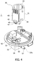
- FIG. 4 is an exploded perspective view of a heating structure according to an embodiment of the present invention.
- the heating structure 1 may include a heating member 30 and the flange 50 having the heating member installed therein.
- the heating structure 1 including the heating member 30 may transfer heat to the pump 9 to melt the frozen aqueous urea solution 5.
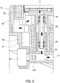
- FIG. 5 is a cross-sectional view of a flange of the heating structure according to an embodiment of the present invention, wherein arrows represent the flow of the liquid.
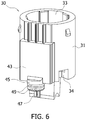
- FIG. 6 is a perspective view of a heating member of the heating structure according to an embodiment of the present invention.
- FIG. 7 is a bottom perspective view of the heating member of the heating structure according to an embodiment of the present invention.
- FIG. 8 is a perspective view of a positive temperature coefficient (PTC) device coupled to a body of the heating structure according to an embodiment of the present invention.
- PTC positive temperature coefficient
- the heating member 30 may include a housing 31, a body 32, and a PTC device 41.
- the heating structure 1 may transfer heat to the PTC device 41, at least a part of the pump 9, and at least a part of the first discharge tube 11 and the second discharge tube 57 so as to melt the frozen aqueous urea solution 5.
- the body 32 may extend in an inward direction of the tank 7, and for example, the body may extend in a vertical direction of the tank, as illustrated in FIG. 3 .
- the body 32 that transfers heat may be installed in the housing 31.
- the housing 31 may be a resin injection-molded product manufactured by injection molding the body 32 using a resin.
- the shape of the body 32 and the shape of the housing 31 may be the same.
- an accommodation groove 33 may be formed in one end of the body 32 that opens in the inward direction of the tank 7, for example, in one end of the body 32 that opens in an upward direction of the tank, as illustrated in FIG. 3 .
- the pump 9 may be vertically inserted into the accommodation groove 33 formed in the body 32.
- a plurality of first inlets 34 may be formed on a lower side surface of the body 32, as illustrated in FIG. 7 , and the plurality of first inlets may be connected to the suction tube 12 of the pump 9.
- the aqueous urea solution 5 may pass through the first inlets 34 of the body 32 and may be introduced into the inside of the pump via the suction tube 12 of the pump 9.
- the body 32 may be formed of aluminum and may have a cylindrical shape with circular cross-sections. However, the body 32 may have one side surface with a plate shape so that the PTC device 41 can be coupled to the outside surface of the body 32.
- the body 32 includes the pump 9 disposed therein and thus surrounds the pump so that heat generated in the body can be directly transferred to the pump.
- the PTC device 41 may have a plate shape with rectangular cross-sections, as illustrated in FIG. 8 , and may generate heat by supplied electrical energy due to characteristics of the PTC device.
- a mounting groove 35 may be formed in one side surface of the body 32 so that the PTC device 41 can be inserted into the body 32 through the mounting groove 35.
- a wall portion 37 may protrude from a circumference of the mounting groove 35.
- the PTC device 41 may be coupled to the body 32 through a cover 43.
- the cover 43 may cover and seal the PTC device 41 and simultaneously may enable the PTC device to be coupled to the body 32.
- the cover 43 may have rectangular cross-sections but may have any shape in which the cover 43 covers and seals the PTC device 41.
- the cover 43 may include a screw hole 43a formed in a corner of the cover so that the PTC device 41 can be coupled to the body 32 using a bolt 44 through the screw hole 43a.
- the cover 43 may be coupled to the wall portion 37 that protrudes from the circumference of the mounting groove 35.
- the cover 43 may be coupled to the wall portion 37 to cover and seal the PTC device 41.
- the PTC device can be fixed to the body 32.
- a gasket 39 may be installed between the wall portion 37 and the cover 43 to seal a space between the wall portion and the cover.
- the gasket 39 may enable the aqueous urea solution 5 not to be permeated into the PTC device 41.
- the heating structure 1 may include a power cutoff unit (not shown).
- the power cutoff unit may be a power sensor, and the power sensor may be electrically connected to the PTC device 41 so that, when the PTC device is at a Curie temperature or higher, the power sensor may cutoff power supplied to the PTC device.
- the Curie temperature is a temperature at which a material loses magnetism.
- a plug 47 may be formed on a lower end of the PTC device 41 to supply electrical energy to the PTC device.
- the plug 47 is electrically connected to the PTC device 41.
- a protrusion 45 may be formed on one side of the PTC device 41 and may protrude toward the flange 50.
- An insertion hole 45a may be formed in one end of the protrusion 45, i.e., in a lower surface of the protrusion, as illustrated in FIG. 7 , so that the plug 47 can be inserted into and pass through the insertion hole 45a. In this case, the plug 47 may be inserted into the insertion hole 45a and may be exposed to the outside of the protrusion.
- FIG. 9 is a perspective view of a pump installed at the heating member of the heating structure according to an embodiment of the present invention.
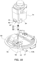
- FIG. 10 is a perspective view of the heating member of the heating structure according to an embodiment of the present invention installed at the flange.
- a first groove 51 may be recessed in one surface of the flange 50 so that the protrusion 45 can be inserted into the one surface of the flange 50 through the first groove 51.
- a socket 55 to be coupled to the plug 47 may be formed in the center of the first groove 51.
- the protrusion 45 and the first groove 51 may have corresponding shapes.
- the protrusion 45 and the insertion hole 45a may have circular cross-sections, as illustrated in FIG. 10 .
- a radius of an outer circumferential surface of the protrusion 45 and a radius of the first groove 51 may be formed in such a way that, when the protrusion is inserted into the first groove, the plug 47 and the socket 55 can be sealed at the radius of the outer circumferential surface of the protrusion 45 and the radius of the first groove 51. That is, the radius of the outer circumferential surface of the protrusion 45 may be smaller than the radius of the first groove 51.
- a first sealing member 49 may be formed on the outer circumferential surface of the protrusion 45 so as to seal the first groove and the protrusion when the protrusion is inserted into the first groove 51.
- the flange 50 may be installed on one surface of the interior of the tank 7, i.e., on the lower side surface of the tank, as illustrated in FIG. 2 , to block a hole (not shown) formed in a lower portion of the tank. That is, the flange 50 may be mounted on the lower portion of the tank 7 so that installation of the flange 50 is simple.
- the pump 9, the heating member 30, the filter 15, and the coupling member 13 may be installed on an upper portion of the flange 50 and may be fixed to the interior of the tank 7.
- a lower portion of the flange 50 may be exposed to the outside of the tank 7 so that the aqueous urea solution 5 can be discharged to the outside of the tank.
- the flange 50 may have a cross section in a shape of a circular plate and may protrude in a downward direction of the circular plate. Embodiments of the present invention are not limited thereto.
- the first groove 51 and a second groove 53 may be formed in a top surface of the flange 50, and a connection tube 59 may be provided in the second groove.
- a second discharge tube 57 connected to the connection tube 59 may be provided on a lower side of the flange 50.
- the second groove 53 of the flange 50 may be formed in one surface of the flange, for example, in the top surface of the flange.
- At least a part of the first discharge tube 11 formed on the lower side surface of the pump 9 may be accommodated in the second groove 53.
- one end of the body 32 for example, a lower end of the body 32 may be accommodated in the second groove 53 together with at least a part of the first discharge tube 11.
- the body 32 may protrude in such a way that a part of the lower end of the body 32 can be inserted into the second groove 53.
- at least a part of the first discharge tube 11 may be heated by the protruding body 32.
- the second discharge tube 57 is a passage through which the aqueous urea solution 5 is discharged to the outside of the flange 50. Meanwhile, one end of the body 32 may be formed to heat a part of the second discharge tube 57.
- the lower end of the protruding body 32 may extend in a horizontal direction to heat a part of the second discharge tube 57.
- the lower end of the protruding body 32 may be formed to correspond to the shape of the second discharge tube so as to heat a part of the second discharge tube 57.
- the shape of the second discharge tube 57 may be a circular tube shape, and in this case, the lower end of the body having a semicircular shape may be formed to surround a part of an upper side of the second discharge tube 57.
- the second discharge tube 57 may be formed on the other side of the flange 50, for example, on the lower side of the flange, as illustrated in FIG. 4 .
- a second inlet 57a of the second discharge tube 57 may be connected to the connection tube 59, and a discharge port 57b of the second discharge tube 57 may extend in the horizontal direction, may pass through side surfaces of the flange 50 and may be exposed to the outside of the flange 50, as illustrated in FIG. 4 .
- the flange 50 may include the connection tube 59 that is formed in the inside of the second groove 53 and connects the first discharge tube 11 to the second discharge tube 57, as illustrated in FIGS. 4 and 5 .
- connection tube 59 may protrude from the inside of the second groove 53 toward the heating member 30.
- a discharge tube 61 may be vertically installed in the connection tube 59.
- the discharge tube 61 may have a linear shape and may be coupled to the first discharge tube 11 of the pump 9.
- a second sealing member 65 may be formed on an outer circumferential surface of the discharge tube 61 so as to seal a space between the discharge tube 61 and the connection tube 59.
- a pressure sensor 63 may be mounted on the second inlet 57a of the second discharge tube 57.
- the pressure sensor 63 compares a current actual measurement pressure with a target pressure to feedback control the pressure of the aqueous urea solution 5 in real time.
- the first discharge tube 11, the second discharge tube 57, the connection tube 59, and the discharge tube 61 may have a tubular shape with circular cross-sections so that the aqueous urea solution 5 can flow therethrough.
- embodiments of the present invention are not limited thereto.
- the heating structure 1 may include a temperature sensor (not shown) that is installed on one surface of the flange 50 and detects the temperature of the aqueous urea solution 5 that is a liquid.
- the temperature sensor may detect the temperature of the aqueous urea solution 5 inside the tank 7 to control an operation of the heating structure 1 and to maintain a constant temperature of the aqueous urea solution around the pump 9.
- the first sealing member 49 and the second sealing member 65 may seal the first groove 51 and the protrusion and the space between the discharge tube 61 and the connection tube 59, respectively, so that the aqueous urea solution 5 does not permeate into the heating structure 1 and the pump module 3 including the same.
- first sealing member 49 and the second sealing member 65 may be compressed at a set compression ratio, may have set thicknesses, and may be manufactured in the form of an O-ring formed of fluorine silicon, for example.
- FIG. 11 is a flowchart illustrating a production method for the heating structure, according to an embodiment of the present invention.
- the production method for the heating structure may include providing a body having a mounting groove formed in one side surface thereof and a wall portion provided at a circumference of the mounting groove (S10), inserting a PTC device into the mounting groove (S20), installing a gasket at the wall portion and coupling a cover to the wall portion (S30), and injection molding the surface of the body to which the cover is coupled, to form a housing (S40).
- the PTC device 41 in a sealed state may be installed at the body 32.
- the surface of the body 32 having the PTC device 41 installed therein may be injection-molded to form the housing 31.
- the mounting groove 35 may be formed in one side surface of the body 32, and the wall portion 37 protrudes from the circumference of the mounting groove.
- the PTC device 41 is inserted into and is installed in the mounting groove 35.
- the area of the mounting groove 35 may be greater than or the same as the area of the PTC device 41.
- the gasket 39 is installed at or applied to the protruding wall portion 37, and the cover 43 is coupled to the wall portion having the gasket installed therein, to seal the PTC device 41.
- the PTC device 41 is installed to inject a molding material into the body 32 to which the cover 43 is coupled, and to manufacture the housing 31.
- the housing 31 may have the same shape as that of the body 32.
- embodiments of the present invention are not limited thereto.
- the heating member 30 may include the housing 31, the body 32, and the PTC device 41.
- a PTC device capable of heating an aqueous urea solution that is easily frozen in the winter season is provided so that the frozen aqueous urea solution can be melted.
- a strongly alkaline aqueous urea solution can be stably pumped using an injector.
- a flange mounted on a lower portion of a tank is provided so that installation of the heating structure in the pump module is simple.
- a body is formed to heat a part of a first discharge tube and a part of a second discharge tube so that the frozen aqueous urea solution that is present in the discharge tube to be discharged to the outside of the pump module can be efficiently melted.
- a PTC device capable of heating an aqueous urea solution is provided so that the frozen aqueous urea solution can be melted and damage caused by electrical overload can be prevented.
- a strongly alkaline aqueous urea solution can be stably pumped using an injector.
- a flange mounted on a lower portion of a tank is provided so that installation of the heating structure in the pump module is simple.
- a body is formed to heat a part of a first discharge tube and a part of a second discharge tube so that the frozen aqueous urea solution that is present in the discharge tube can be efficiently melted.
Landscapes
- Engineering & Computer Science (AREA)
- Chemical & Material Sciences (AREA)
- Chemical Kinetics & Catalysis (AREA)
- Combustion & Propulsion (AREA)
- Mechanical Engineering (AREA)
- General Engineering & Computer Science (AREA)
- Health & Medical Sciences (AREA)
- Toxicology (AREA)
- Transportation (AREA)
- Life Sciences & Earth Sciences (AREA)
- Sustainable Development (AREA)
- Sustainable Energy (AREA)
- Exhaust Gas After Treatment (AREA)
Description
- The present invention relates to a heating structure, a production method therefor, and a pump module including the same.
- In general, an exhaust system for a diesel engine includes an exhaust gas post-processing unit, such as a selective catalyst reduction (SCR) unit, a diesel oxidation catalyst (DOC) unit, a catalyzed particulate filter (CPF), so as to reduce a nitrogen oxide (NOx) contained in exhaust gas.
- Among them, an exhaust gas post-processing unit that applies SCR (hereinafter, referred to as an 'SCR unit') performs a function of injecting a reductant, such as an aqueous urea solution, into an inside of an exhaust pipe to reduce NOx in the exhaust gas into nitrogen and oxygen.
- That is, in the SCR unit, when the reductant is injected into the inside of the exhaust pipe, the reductant can be changed to ammonia (NH3) by heat of the exhaust gas, and NOx can be reduced into nitrogen gas (N2) and water (H2O) as a catalyst reaction of NOx in the exhaust gas and ammonia using an SCR catalyst.
- In this way, a system for supplying the aqueous urea solution to the SCR unit is required to inject the aqueous urea solution into the inside of the exhaust pipe using the SCR unit.
- The system for supplying the aqueous urea solution basically includes a urea tank for storing the aqueous urea solution and a pump module that is disposed in the urea tank and supplies the aqueous urea solution to the SCR unit.
- In the related art, as specific gravity of the aqueous urea solution increases in the winter season, freezing is sequentially performed from a lower portion of the urea tank, and as the volume of the aqueous urea solution expands due to freezing, great deformation may occur in an upper portion of the urea tank.
- In addition, in the related art, a heating device and a pump are installed to be spaced by a predetermined distance apart from each other. Thus, it is not easy to melt the frozen aqueous urea solution that is present in the pump.
-
- The present invention is directed to providing a heating structure for stably pumping a strongly alkaline aqueous urea solution using an injector and melting the frozen aqueous urea solution in the winter season, a production method therefor, and a pump module including the same.
- According to the invention, there is provided a pump module as set out in
claim 1. - One aspect of the present invention provides a heating structure, which is for heating a pump installed in a tank so as to discharge a liquid stored in the tank to the outside of the tank, including: a flange installed on one surface of the interior of the tank; and a heating member coupled to one surface of the flange and provided on one side thereof with an accommodation groove in which at least a part of the pump is accommodated, wherein a first discharge tube of the pump having at least a part thereof accommodated in the accommodation groove extends toward the flange and is connected to a second discharge tube formed on the other surface of the flange outside the tank, and the heating member is formed to heat at least a part of the pump, at least a part of the first discharge tube, and at least a part of the second discharge tube.
- The heating member may include: a body that extends in an inward direction of the tank; and a positive temperature coefficient (PTC) device coupled to an outside surface of the body, and the accommodation groove may be formed in an end that opens in the inward direction of the tank of the body.
- The heating structure may further include a cover coupled to the body so as to cover and seal the PTC device.
- A protrusion may be formed on one side of the PTC device and may protrude toward the flange, and a plug connected to the PTC device may be formed on an end of the protrusion, and a first groove may be recessed in the one surface of the flange so that the protrusion is inserted into the first groove, and a socket corresponding to the plug may be formed in a center of the first groove.
- The heating structure may further include a first sealing member formed on an outer circumferential surface of the protrusion.
- The heating structure may further include: a mounting groove formed in one side surface of the body so that the PTC device is inserted into the body through the mounting groove; and a wall portion formed at a circumference of the mounting groove, wherein the cover may be coupled to the wall portion to cover and seal the PTC device and to fix the PTC device to the body.
- The heating structure may further include a gasket disposed between the wall portion and the cover and sealing a space between the wall portion and the cover.
- The heating structure may further include a power cutoff unit that cuts off power supplied to the PTC device when the power cutoff unit is electrically connected to the PTC device and the PTC device is at a Curie temperature or higher.
- The heating structure may further include a temperature sensor that is installed on one surface of the flange and detects a temperature of the liquid.
- A second groove may be formed in one surface of the flange to accommodate at least a part of the first discharge tube, and one end of the body capable of heating at least a part of the first discharge tube may be accommodated in the second groove together with at least a part of the first discharge tube.
- One end of the body may be formed to heat a part of the second discharge tube.
- A connection tube may be formed in the second groove of the flange, may protrude from an interior of the second groove of the flange, may extend toward the heating member and may connect the first discharge tube to the second discharge tube.
- The heating structure may further include a linear discharge tube coupled to the first discharge tube, wherein the discharge tube may be disposed in the connection tube while being coupled to the first discharge tube.
- The heating structure may further include a second sealing member formed at an outer circumferential surface of the discharge tube so as to seal a space between the discharge tube and the connection tube.
- The tank may be a storage tank for storing an aqueous urea solution. According to the present invention , the pump module includes a pump installable in a storage tank so as to discharge a liquid stored in the storage tank to an outside of the storage tank; the above-described heating structure disposed to surround an outside surface of the pump; a coupling member coupled to an outside of the pump so as to couple the heating structure to the flange; and a filter coupled to the flange to surround the pump, the coupling member and the heating structure and filtering the liquid supplied to the pump.
- There is also provided a production method for a heating structure, including: providing a body having a mounting groove formed in one side surface thereof and a wall portion provided at a circumference of the mounting groove; inserting a positive temperature coefficient (PTC) device into the mounting groove; installing a gasket at the wall portion and coupling a cover to the wall portion; and injection molding a surface of the body to which the cover is coupled, to form a housing.
- In a heating structure according to an embodiment of the present invention and a production method therefor, a frozen aqueous urea solution can be melted using a positive temperature coefficient (PTC) device capable of heating the aqueous urea solution, and damage caused by electrical overload can be prevented.
- In a pump module according to an embodiment of the present invention, a strongly alkaline aqueous urea solution can be stably pumped using an injector.
- In a heating structure according to an embodiment of the present invention and a pump module including the same, a flange mounted on a lower portion of a tank is provided so that installation of the heating structure in the pump module is simple.
- In a heating structure according to an embodiment of the present invention, a body is formed to heat a part of a first discharge tube and a part of a second discharge tube so that the frozen aqueous urea solution that is present in the discharge tube of the pump module can be efficiently melted.
-
-
FIG. 1 is a perspective view showing a state in which a pump module having a heating structure mounted thereon according to an embodiment of the present invention is installed in a tank. -
FIG. 2 is a perspective view of the pump module having the heating structure mounted thereon according to an embodiment of the present invention. -
FIG. 3 is a cross-sectional view taken along a line A-A ofFIG. 2 , wherein arrows represent a flow of a liquid. -
FIG. 4 is an exploded perspective view of the heating structure according to an embodiment of the present invention. -
FIG. 5 is a cross-sectional view of a flange of the heating structure according to an embodiment of the present invention, wherein arrows represent the flow of the liquid. -
FIG. 6 is a perspective view of a heating member of the heating structure according to an embodiment of the present invention. -
FIG. 7 is a bottom perspective view of the heating member of the heating structure according to an embodiment of the present invention. -
FIG. 8 is a perspective view of a positive temperature coefficient (PTC) device coupled to a body of the heating structure according to an embodiment of the present invention. -
FIG. 9 is a perspective view of a pump installed at the heating member of the heating structure according to an embodiment of the present invention. -
FIG. 10 is a perspective view of the heating member of the heating structure according to an embodiment of the present invention installed at the flange. -
FIG. 11 is a flowchart illustrating a production method for the heating structure, according to an embodiment of the present invention. - Hereinafter, exemplary embodiments of the present invention will be described in detail with reference to the attached drawings in order to enable those of ordinary skill in the art to easily embody and practice the invention. The present invention can be implemented in several different forms and is not limited to the exemplary embodiments disclosed below. In order to clearly describe the present invention, portions irrelevant to the description are omitted in the drawings, and like reference numerals throughout the specification denote like elements.
- In the present specification, it is to be understood that the terms such as "including" or "having," etc., are intended to indicate the existence of the features, numbers, steps, actions, components, parts, or combinations thereof disclosed in the specification, and are not intended to preclude the possibility that one or more other features, numbers, steps, actions, components, parts, or combinations thereof may exist or may be added. It will be understood that, when a portion such as a layer, a film, a region or a plate is referred to as being "on" another portion, the portion can be "directly on" another portion or on intervening portions. In contrast, when a portion such as a layer, a film, a region or a plate is referred to as being "under" another portion, the portion can be "directly under" another portion or under intervening portions.
- Hereinafter, a heating structure according to an embodiment of the present invention and a pump module including the same will be described in more detail with reference to the drawings.
-
FIG. 1 is a perspective view showing a state in which a pump module having a heating structure mounted thereon according to an embodiment of the present invention is installed in a tank.FIG. 2 is a perspective view of the pump module having the heating structure mounted thereon according to an embodiment of the present invention.FIG. 3 is a cross-sectional view taken along a line A-A ofFIG. 2 , wherein arrows represent a flow of a liquid. - Referring to
FIGS. 1 through 3 , apump module 3 having aheating structure 1 mounted thereon according to an embodiment of the present invention may include apump 9, theheating structure 1, acoupling member 13, and afilter 15. - In this case, the
pump module 3 may be installed in atank 7 in which a liquid is stored, and may pump the liquid using an injector (not shown) installed outside the tank stably. - In addition, the
pump module 3 may perform a function of adjusting the temperature and level of the liquid stored in thetank 7 and filtering the liquid stored in thetank 7 and may melt the frozen liquid using theheating structure 1 installed therein. This enables the frozen liquid to be firstly melted before thepump 9 operates, so that the pump can operate smoothly. - Referring to
FIGS. 1 through 3 , in an embodiment of the present invention, the liquid stored in thestorage tank 7 may be anaqueous urea solution 5 used as a reductant. In this case, theaqueous urea solution 5 is colorless, odorless, nonpoisonous, unburnable, and strongly alkaline (PH 10 or higher) and is mixed in water at the ratio of 32.5%. - A freezing point of the
aqueous urea solution 5 that is strongly alkaline is -11.5 °C, and a volume of theaqueous urea solution 5 at the freezing point expands by 11%. Thus, when theaqueous urea solution 5 stored in the pump module is frozen, the volume of the aqueous urea solution expands, which may cause damage of thepump module 3. - Thus, the
pump module 3 may be installed in thetank 7 in which the aqueous urea solution is stored, and may pump the strongly alkaline aqueous urea solution using the injector (not shown) installed outside the tank stably. - Referring to
FIG. 3 , in an embodiment of the present invention, thepump 9 is installed in thetank 7 and pumps theaqueous urea solution 5 stored in thetank 7 to the outside of the tank. - Meanwhile, a
suction tube 12 and afirst discharge tube 11 of thepump 9 may be formed on a lower side surface of the pump while being adjacent to each other. Thus, theaqueous urea solution 5 is sucked into the pump via thesuction tube 12 formed on the lower side surface of the pump and is discharged to the outside of the pump via thefirst discharge tube 11. - The
suction tube 12 and thefirst discharge tube 11 of thepump 9 are installed adjacent to each other so that theaqueous urea solution 5 suctioned via thesuction tube 12 does not pass through a motor (not shown) disposed in the pump but is directly discharged via thefirst discharge tube 11 and thus the motor can be protected. - Meanwhile, the
heating structure 1 according to an embodiment of the present invention is disposed to surround an outside surface of thepump 9. In this case, theheating structure 1 may transfer heat to thepump 9 and may melt the frozenaqueous urea solution 5. - Referring to
FIG. 3 , in an embodiment of the present invention, thecoupling member 13 is provided to couple theheating structure 1 to thepump 9. - In this case, the
coupling member 13 may be coupled to the outside of thepump 9 to couple theheating structure 1 to aflange 50 so that theheating structure 1 can be fixed to the interior of thetank 7. - Meanwhile, referring to
FIGS. 1 through 3 , thefilter 15 may be disposed to surround thepump 9, thecoupling member 13, and theheating structure 1. In this case, thefilter 15 may be coupled to theflange 50, and a plurality offilter media 17 may be disposed on an outside surface of the filter. - In this case, the
filter 15 filters theaqueous urea solution 5 stored in thetank 7 using thefilter media 17 and supplies the filteredaqueous urea solution 5 to thepump 9, as illustrated inFIG. 3 . -
FIG. 4 is an exploded perspective view of a heating structure according to an embodiment of the present invention. - Referring to
FIG. 4 , theheating structure 1 according to an embodiment of the present invention may include aheating member 30 and theflange 50 having the heating member installed therein. In this case, theheating structure 1 including theheating member 30 may transfer heat to thepump 9 to melt the frozenaqueous urea solution 5. -
FIG. 5 is a cross-sectional view of a flange of the heating structure according to an embodiment of the present invention, wherein arrows represent the flow of the liquid.FIG. 6 is a perspective view of a heating member of the heating structure according to an embodiment of the present invention.FIG. 7 is a bottom perspective view of the heating member of the heating structure according to an embodiment of the present invention.FIG. 8 is a perspective view of a positive temperature coefficient (PTC) device coupled to a body of the heating structure according to an embodiment of the present invention. - Referring to
FIGS. 5 through 8 , in an embodiment of the present invention, theheating member 30 may include ahousing 31, abody 32, and aPTC device 41. - The
heating structure 1 according to an embodiment of the present invention may transfer heat to thePTC device 41, at least a part of thepump 9, and at least a part of thefirst discharge tube 11 and thesecond discharge tube 57 so as to melt the frozenaqueous urea solution 5. - In addition, when electrical overload is applied to the
PTC device 41 due to characteristics of thePTC device 41, power is cut off so that damage caused by electrical overload can be prevented. - Meanwhile, referring to
FIGS. 1 and3 , thebody 32 may extend in an inward direction of thetank 7, and for example, the body may extend in a vertical direction of the tank, as illustrated inFIG. 3 . - In an embodiment of the present invention, referring to
FIG. 3 , thebody 32 that transfers heat may be installed in thehousing 31. Thehousing 31 may be a resin injection-molded product manufactured by injection molding thebody 32 using a resin. Thus, the shape of thebody 32 and the shape of thehousing 31 may be the same. - In addition, referring to
FIGS. 3 through 5 , anaccommodation groove 33 may be formed in one end of thebody 32 that opens in the inward direction of thetank 7, for example, in one end of thebody 32 that opens in an upward direction of the tank, as illustrated inFIG. 3 . - In this case, the
pump 9 may be vertically inserted into theaccommodation groove 33 formed in thebody 32. In addition, a plurality offirst inlets 34 may be formed on a lower side surface of thebody 32, as illustrated inFIG. 7 , and the plurality of first inlets may be connected to thesuction tube 12 of thepump 9. - In this case, the
aqueous urea solution 5 may pass through thefirst inlets 34 of thebody 32 and may be introduced into the inside of the pump via thesuction tube 12 of thepump 9. - Referring to
FIG. 6 , thebody 32 may be formed of aluminum and may have a cylindrical shape with circular cross-sections. However, thebody 32 may have one side surface with a plate shape so that thePTC device 41 can be coupled to the outside surface of thebody 32. - In addition, the
body 32 includes thepump 9 disposed therein and thus surrounds the pump so that heat generated in the body can be directly transferred to the pump. - In this case, the
PTC device 41 may have a plate shape with rectangular cross-sections, as illustrated inFIG. 8 , and may generate heat by supplied electrical energy due to characteristics of the PTC device. - Meanwhile, referring to
FIG. 8 , in an embodiment of the present invention, a mountinggroove 35 may be formed in one side surface of thebody 32 so that thePTC device 41 can be inserted into thebody 32 through the mountinggroove 35. In addition, awall portion 37 may protrude from a circumference of the mountinggroove 35. - In an embodiment of the present invention, the
PTC device 41 may be coupled to thebody 32 through acover 43. In this case, thecover 43 may cover and seal thePTC device 41 and simultaneously may enable the PTC device to be coupled to thebody 32. - Referring to
FIG. 8 , thecover 43 may have rectangular cross-sections but may have any shape in which thecover 43 covers and seals thePTC device 41. - In addition, the
cover 43 may include ascrew hole 43a formed in a corner of the cover so that thePTC device 41 can be coupled to thebody 32 using abolt 44 through thescrew hole 43a. - Meanwhile, referring to
FIG. 8 , in an embodiment of the present invention, thecover 43 may be coupled to thewall portion 37 that protrudes from the circumference of the mountinggroove 35. Thecover 43 may be coupled to thewall portion 37 to cover and seal thePTC device 41. Thus, the PTC device can be fixed to thebody 32. - In this case, a
gasket 39 may be installed between thewall portion 37 and thecover 43 to seal a space between the wall portion and the cover. Thegasket 39 may enable theaqueous urea solution 5 not to be permeated into thePTC device 41. - Meanwhile, the
heating structure 1 according to an embodiment of the present invention may include a power cutoff unit (not shown). - The power cutoff unit may be a power sensor, and the power sensor may be electrically connected to the
PTC device 41 so that, when the PTC device is at a Curie temperature or higher, the power sensor may cutoff power supplied to the PTC device. In this case, the Curie temperature is a temperature at which a material loses magnetism. - Referring to
FIG. 8 , aplug 47 may be formed on a lower end of thePTC device 41 to supply electrical energy to the PTC device. Theplug 47 is electrically connected to thePTC device 41. - Referring to
FIGS. 6 through 8 , aprotrusion 45 may be formed on one side of thePTC device 41 and may protrude toward theflange 50. - An
insertion hole 45a may be formed in one end of theprotrusion 45, i.e., in a lower surface of the protrusion, as illustrated inFIG. 7 , so that theplug 47 can be inserted into and pass through theinsertion hole 45a. In this case, theplug 47 may be inserted into theinsertion hole 45a and may be exposed to the outside of the protrusion. -
FIG. 9 is a perspective view of a pump installed at the heating member of the heating structure according to an embodiment of the present invention.FIG. 10 is a perspective view of the heating member of the heating structure according to an embodiment of the present invention installed at the flange. - Referring to
FIG. 10 , afirst groove 51 may be recessed in one surface of theflange 50 so that theprotrusion 45 can be inserted into the one surface of theflange 50 through thefirst groove 51. In addition, asocket 55 to be coupled to theplug 47 may be formed in the center of thefirst groove 51. - Referring to
FIGS. 9 and10 , theprotrusion 45 and thefirst groove 51 may have corresponding shapes. For example, theprotrusion 45 and theinsertion hole 45a may have circular cross-sections, as illustrated inFIG. 10 . - In addition, a radius of an outer circumferential surface of the
protrusion 45 and a radius of thefirst groove 51 may be formed in such a way that, when the protrusion is inserted into the first groove, theplug 47 and thesocket 55 can be sealed at the radius of the outer circumferential surface of theprotrusion 45 and the radius of thefirst groove 51. That is, the radius of the outer circumferential surface of theprotrusion 45 may be smaller than the radius of thefirst groove 51. - In addition, a first sealing
member 49 may be formed on the outer circumferential surface of theprotrusion 45 so as to seal the first groove and the protrusion when the protrusion is inserted into thefirst groove 51. - Meanwhile, referring to
FIGS. 2 through 4 , theflange 50 may be installed on one surface of the interior of thetank 7, i.e., on the lower side surface of the tank, as illustrated inFIG. 2 , to block a hole (not shown) formed in a lower portion of the tank. That is, theflange 50 may be mounted on the lower portion of thetank 7 so that installation of theflange 50 is simple. - In this case, referring to
FIG. 3 , thepump 9, theheating member 30, thefilter 15, and thecoupling member 13 may be installed on an upper portion of theflange 50 and may be fixed to the interior of thetank 7. In addition, a lower portion of theflange 50 may be exposed to the outside of thetank 7 so that theaqueous urea solution 5 can be discharged to the outside of the tank. - Referring to
FIGS. 3 and4 , theflange 50 may have a cross section in a shape of a circular plate and may protrude in a downward direction of the circular plate. Embodiments of the present invention are not limited thereto. - Referring to
FIG. 4 , thefirst groove 51 and asecond groove 53 may be formed in a top surface of theflange 50, and aconnection tube 59 may be provided in the second groove. In addition, asecond discharge tube 57 connected to theconnection tube 59 may be provided on a lower side of theflange 50. - Referring to
FIG. 4 , in an embodiment of the present invention, thesecond groove 53 of theflange 50 may be formed in one surface of the flange, for example, in the top surface of the flange. - Referring to
FIGS. 4 and5 , at least a part of thefirst discharge tube 11 formed on the lower side surface of thepump 9 may be accommodated in thesecond groove 53. - Meanwhile, referring to
FIGS. 4 and5 , one end of thebody 32, for example, a lower end of thebody 32 may be accommodated in thesecond groove 53 together with at least a part of thefirst discharge tube 11. - In this case, the
body 32 may protrude in such a way that a part of the lower end of thebody 32 can be inserted into thesecond groove 53. In addition, at least a part of thefirst discharge tube 11 may be heated by the protrudingbody 32. - Referring to
FIG. 3 , thesecond discharge tube 57 is a passage through which theaqueous urea solution 5 is discharged to the outside of theflange 50. Meanwhile, one end of thebody 32 may be formed to heat a part of thesecond discharge tube 57. - That is, the lower end of the protruding
body 32 may extend in a horizontal direction to heat a part of thesecond discharge tube 57. - In this case, the lower end of the protruding
body 32 may be formed to correspond to the shape of the second discharge tube so as to heat a part of thesecond discharge tube 57. As illustrated inFIG. 4 , the shape of thesecond discharge tube 57 may be a circular tube shape, and in this case, the lower end of the body having a semicircular shape may be formed to surround a part of an upper side of thesecond discharge tube 57. - Referring to
FIGS. 4 and5 , in an embodiment of the present invention, thesecond discharge tube 57 may be formed on the other side of theflange 50, for example, on the lower side of the flange, as illustrated inFIG. 4 . - In this case, a
second inlet 57a of thesecond discharge tube 57 may be connected to theconnection tube 59, and adischarge port 57b of thesecond discharge tube 57 may extend in the horizontal direction, may pass through side surfaces of theflange 50 and may be exposed to the outside of theflange 50, as illustrated inFIG. 4 . - Meanwhile, in an embodiment of the present invention, the
flange 50 may include theconnection tube 59 that is formed in the inside of thesecond groove 53 and connects thefirst discharge tube 11 to thesecond discharge tube 57, as illustrated inFIGS. 4 and5 . - In this case, the
connection tube 59 may protrude from the inside of thesecond groove 53 toward theheating member 30. - Meanwhile, referring to
FIGS. 5 and10 , adischarge tube 61 may be vertically installed in theconnection tube 59. In this case, thedischarge tube 61 may have a linear shape and may be coupled to thefirst discharge tube 11 of thepump 9. - In this case, a
second sealing member 65 may be formed on an outer circumferential surface of thedischarge tube 61 so as to seal a space between thedischarge tube 61 and theconnection tube 59. - Meanwhile, as illustrated in
FIG. 5 , apressure sensor 63 may be mounted on thesecond inlet 57a of thesecond discharge tube 57. Thepressure sensor 63 compares a current actual measurement pressure with a target pressure to feedback control the pressure of theaqueous urea solution 5 in real time. - In an embodiment of the present invention, the
first discharge tube 11, thesecond discharge tube 57, theconnection tube 59, and thedischarge tube 61 may have a tubular shape with circular cross-sections so that theaqueous urea solution 5 can flow therethrough. However, embodiments of the present invention are not limited thereto. - Meanwhile, the
heating structure 1 according to an embodiment of the present invention may include a temperature sensor (not shown) that is installed on one surface of theflange 50 and detects the temperature of theaqueous urea solution 5 that is a liquid. - In this case, in an embodiment of the present invention, the temperature sensor may detect the temperature of the
aqueous urea solution 5 inside thetank 7 to control an operation of theheating structure 1 and to maintain a constant temperature of the aqueous urea solution around thepump 9. - In an embodiment of the present invention, the first sealing
member 49 and the second sealingmember 65 may seal thefirst groove 51 and the protrusion and the space between thedischarge tube 61 and theconnection tube 59, respectively, so that theaqueous urea solution 5 does not permeate into theheating structure 1 and thepump module 3 including the same. - In this case, the first sealing
member 49 and the second sealingmember 65 may be compressed at a set compression ratio, may have set thicknesses, and may be manufactured in the form of an O-ring formed of fluorine silicon, for example. -
FIG. 11 is a flowchart illustrating a production method for the heating structure, according to an embodiment of the present invention. - Referring to
FIG. 11 , the production method for the heating structure may include providing a body having a mounting groove formed in one side surface thereof and a wall portion provided at a circumference of the mounting groove (S10), inserting a PTC device into the mounting groove (S20), installing a gasket at the wall portion and coupling a cover to the wall portion (S30), and injection molding the surface of the body to which the cover is coupled, to form a housing (S40). - Thus, the
PTC device 41 in a sealed state may be installed at thebody 32. Also, the surface of thebody 32 having thePTC device 41 installed therein may be injection-molded to form thehousing 31. - Meanwhile, in providing of the body having the mounting groove formed in one side surface thereof and the wall portion provided at the circumference of the mounting groove (S10), the mounting
groove 35 may be formed in one side surface of thebody 32, and thewall portion 37 protrudes from the circumference of the mounting groove. - In addition, in inserting of the PTC device into the mounting groove (S20), the
PTC device 41 is inserted into and is installed in the mountinggroove 35. In this case, the area of the mountinggroove 35 may be greater than or the same as the area of thePTC device 41. - Meanwhile, in installing of the gasket at the wall portion and coupling the cover to the wall portion (S30), the
gasket 39 is installed at or applied to the protrudingwall portion 37, and thecover 43 is coupled to the wall portion having the gasket installed therein, to seal thePTC device 41. - In addition, in injection molding of the surface of the body to which the cover is coupled, to form the housing (S40), the
PTC device 41 is installed to inject a molding material into thebody 32 to which thecover 43 is coupled, and to manufacture thehousing 31. - In this case, the
housing 31 may have the same shape as that of thebody 32. However, embodiments of the present invention are not limited thereto. - Meanwhile, the
heating member 30 may include thehousing 31, thebody 32, and thePTC device 41. - In a heating structure according to an embodiment of the present invention and a production method therefor, a PTC device capable of heating an aqueous urea solution that is easily frozen in the winter season is provided so that the frozen aqueous urea solution can be melted.
- In a pump module according to an embodiment of the present invention, a strongly alkaline aqueous urea solution can be stably pumped using an injector.
- In a heating structure according to an embodiment of the present invention and a pump module including the same, a flange mounted on a lower portion of a tank is provided so that installation of the heating structure in the pump module is simple.
- In a heating structure according to an embodiment of the present invention, a body is formed to heat a part of a first discharge tube and a part of a second discharge tube so that the frozen aqueous urea solution that is present in the discharge tube to be discharged to the outside of the pump module can be efficiently melted.
- While the invention has been shown and described with reference to certain exemplary embodiments thereof, it will be understood by those skilled in the art that various changes in form and details may be made therein without departing from the scope of the invention as defined by the appended claims.
- In a heating structure according to an embodiment of the present invention and a production method therefor, a PTC device capable of heating an aqueous urea solution is provided so that the frozen aqueous urea solution can be melted and damage caused by electrical overload can be prevented.
- In a pump module according to an embodiment of the present invention, a strongly alkaline aqueous urea solution can be stably pumped using an injector.
- In a heating structure according to an embodiment of the present invention and a pump module including the same, a flange mounted on a lower portion of a tank is provided so that installation of the heating structure in the pump module is simple.
- In a heating structure according to an embodiment of the present invention, a body is formed to heat a part of a first discharge tube and a part of a second discharge tube so that the frozen aqueous urea solution that is present in the discharge tube can be efficiently melted.
Claims (15)
- A pump module (3) comprising:a pump (9) installable in a storage tank (7) so as to discharge a liquid stored in the storage tank (7) to the outside of the storage tank (7);a flange (50) installable on one surface of the interior of the storage tank (7);a heating member (30) disposed to surround an outside surface of the pump (9) and coupled to one surface of the flange (50) and provided on one side thereof with an accommodation groove (33) in which at least a part of the pump (9) is accommodated;a coupling member (13) coupled to an outside of the pump (9) so as to couple the heating member (30) to the flange (50); anda filter (15) coupled to the flange (50) to surround the pump (9), the coupling member (13) and the heating member (30) and filtering the liquid supplied to the pump (9),wherein a first discharge tube (11) of the pump (9) having at least a part thereof accommodated in the accommodation groove (33) extends toward the flange (50) and is connectable to a second discharge tube (57) formed on the other surface of the flange (50) outside the storage tank (7), and the heating member (30) is formed to heat at least a part of the pump (9), at least a part of the first discharge tube (11), and at least a part of the second discharge tube (57).
- The pump module of claim 1, wherein the heating member comprises:a body (32) that extends in an inward direction of the storage tank; anda positive temperature coefficient (PTC) device (41) coupled to an outside surface of the body, andthe accommodation groove is formed in an end that opens in the inward direction of the storage tank of the body.
- The pump module of claim 2, further comprising a cover (43) coupled to the body so as to cover and seal the PTC device.
- The pump module of claim 2, wherein a protrusion (45) is formed on one side of the PTC device and protrudes toward the flange, and a plug (47) connected to the PTC device is formed on an end of the protrusion, and a first groove (51) is recessed in the one surface of the flange so that the protrusion is inserted into the first groove, and a socket (55) corresponding to the plug is formed in a center of the first groove.
- The pump module of claim 4, further comprising a first sealing member (49) formed on an outer circumferential surface of the protrusion.
- The pump module of claim 3, further comprising:a mounting groove (35) formed in one side surface of the body so that the PTC device is inserted into the body through the mounting groove; anda wall portion (37) formed at an edge of the mounting groove,wherein the cover is coupled to the wall portion to cover and seal the PTC device and to fix the PTC device to the body.
- The pump module of claim 6, further comprising a gasket (39) disposed between the wall portion and the cover and sealing a space between the wall portion and the cover.
- The pump module of claim 2, further comprising a power cutoff unit that cuts off power supplied to the PTC device when the power cutoff unit is electrically connected to the PTC device and the PTC device is at a Curie temperature or higher.
- The pump module of claim 1, further comprising a temperature sensor that is installed on one surface of the flange and detects a temperature of the liquid.
- The pump module of claim 2, wherein a second groove (53) is formed in one surface of the flange to accommodate at least a part of the first discharge tube, and one end of the body capable of heating at least a part of the first discharge tube is accommodated in the second groove together with at least a part of the first discharge tube.
- The pump module of claim 2, wherein one end of the body is formed to heat a part of the second discharge tube.
- The pump module of claim 11, wherein a connection tube (59) is formed in the second groove of the flange, protrudes from an interior of the second groove of the flange, extends toward the heating member and connects the first discharge tube to the second discharge tube.
- The pump module of claim 12, further comprising a linear discharge tube (61) coupled to the first discharge tube, wherein the discharge tube is disposed in the connection tube while being coupled to the first discharge tube.
- The pump module of claim 13, further comprising a second sealing member (65) formed at an outer circumferential surface of the discharge tube so as to seal a space between the discharge tube and the connection tube.
- The pump module of claim 1, wherein the storage tank is for storing an aqueous urea solution.
Applications Claiming Priority (2)
| Application Number | Priority Date | Filing Date | Title |
|---|---|---|---|
| KR1020150027573A KR101647959B1 (en) | 2015-02-26 | 2015-02-26 | Heating structure, manufacturing method thereof and pump module having the same |
| PCT/KR2016/001780 WO2016137215A1 (en) | 2015-02-26 | 2016-02-24 | Heating structure, production method therefor, and pump module comprising same |
Publications (3)
| Publication Number | Publication Date |
|---|---|
| EP3263861A1 EP3263861A1 (en) | 2018-01-03 |
| EP3263861A4 EP3263861A4 (en) | 2018-08-15 |
| EP3263861B1 true EP3263861B1 (en) | 2019-08-07 |
Family
ID=56788703
Family Applications (1)
| Application Number | Title | Priority Date | Filing Date |
|---|---|---|---|
| EP16755865.9A Active EP3263861B1 (en) | 2015-02-26 | 2016-02-24 | Heating structure, production method therefor, and pump module comprising same |
Country Status (5)
| Country | Link |
|---|---|
| US (1) | US20180045098A1 (en) |
| EP (1) | EP3263861B1 (en) |
| KR (1) | KR101647959B1 (en) |
| CN (1) | CN107295804B (en) |
| WO (1) | WO2016137215A1 (en) |
Families Citing this family (8)
| Publication number | Priority date | Publication date | Assignee | Title |
|---|---|---|---|---|
| KR101770376B1 (en) * | 2016-09-21 | 2017-09-05 | 주식회사 코아비스 | Urea solution pump module |
| KR102261542B1 (en) * | 2017-03-27 | 2021-06-04 | 현대자동차주식회사 | Urea pump module |
| DE102017217819A1 (en) | 2017-10-06 | 2019-04-11 | Kautex Textron Gmbh & Co. Kg | Liquid container for a motor vehicle |
| KR102383366B1 (en) * | 2017-10-18 | 2022-04-06 | 현대자동차주식회사 | Urea pump module for vehicle |
| FR3096738B1 (en) * | 2019-05-31 | 2021-05-28 | Plastic Omnium Advanced Innovation & Res | Fixing device for the aqueous solution distribution module contained in a tank on board a motor vehicle |
| US11268419B2 (en) * | 2019-08-16 | 2022-03-08 | Caterpillar Inc. | Filter assembly for reductant storage system |
| CN110670149A (en) * | 2019-09-26 | 2020-01-10 | 福建新创锦纶实业有限公司 | Hollow spinneret plate and using method thereof |
| WO2022137216A1 (en) * | 2020-12-21 | 2022-06-30 | Padmini Vna Mechatronics Ltd. | Urea pressure and temperature sensor with improved sealing |
Family Cites Families (10)
| Publication number | Priority date | Publication date | Assignee | Title |
|---|---|---|---|---|
| DE202007006636U1 (en) * | 2007-05-07 | 2007-07-26 | Eichenauer Heizelemente Gmbh & Co. Kg | Liquid container and reducing agent supply system with such a liquid container |
| DE102009039567A1 (en) * | 2009-09-01 | 2011-03-03 | Mahle International Gmbh | filter cartridge |
| DE102010004612A1 (en) * | 2010-01-13 | 2011-07-14 | Emitec Gesellschaft für Emissionstechnologie mbH, 53797 | Device with a tank and a delivery unit for reducing agent |
| DE102010014314A1 (en) * | 2010-04-09 | 2011-10-13 | Emitec Gesellschaft Für Emissionstechnologie Mbh | Device for providing liquid reducing agent |
| US20130000743A1 (en) * | 2011-06-29 | 2013-01-03 | Ti Group Automotive Systems, L.L.C. | Scr fluid distribution and circulation system |
| EP2650497A1 (en) * | 2012-04-11 | 2013-10-16 | TI Automotive Fuel Systems SAS | A system for storing an additive solution for a vehicle engine |
| KR101484205B1 (en) * | 2012-11-12 | 2015-01-16 | 현대자동차 주식회사 | Heater of urea supply system for selective catalyst reduction device |
| KR101427963B1 (en) * | 2012-12-12 | 2014-08-08 | 현대자동차 주식회사 | Heater of urea supply system for selective catalyst reduction device and control method of the same |
| KR101490931B1 (en) * | 2013-08-13 | 2015-02-06 | 현대자동차 주식회사 | Urea solution pumping module |
| DE102014107863A1 (en) * | 2014-06-04 | 2015-12-17 | Emitec Gesellschaft Für Emissionstechnologie Mbh | Method for functional testing of at least one PTC heating element |
-
2015
- 2015-02-26 KR KR1020150027573A patent/KR101647959B1/en active Active
-
2016
- 2016-02-24 EP EP16755865.9A patent/EP3263861B1/en active Active
- 2016-02-24 US US15/554,005 patent/US20180045098A1/en not_active Abandoned
- 2016-02-24 CN CN201680011753.XA patent/CN107295804B/en active Active
- 2016-02-24 WO PCT/KR2016/001780 patent/WO2016137215A1/en not_active Ceased
Also Published As
| Publication number | Publication date |
|---|---|
| EP3263861A1 (en) | 2018-01-03 |
| CN107295804B (en) | 2019-08-06 |
| US20180045098A1 (en) | 2018-02-15 |
| KR101647959B1 (en) | 2016-08-23 |
| EP3263861A4 (en) | 2018-08-15 |
| WO2016137215A1 (en) | 2016-09-01 |
| CN107295804A (en) | 2017-10-24 |
Similar Documents
| Publication | Publication Date | Title |
|---|---|---|
| EP3263861A1 (en) | Heating structure, production method therefor, and pump module comprising same | |
| KR101724478B1 (en) | pump module | |
| US20130269789A1 (en) | System for storing an additive solution for a vehicle engine | |
| US10100693B2 (en) | Urea solution pump unit | |
| KR101451074B1 (en) | Tank assembly and metering system for a reducing agent | |
| EP2837785B1 (en) | Urea solution pumping module | |
| KR101661373B1 (en) | Rotary pump for a vehicle | |
| US10016710B2 (en) | Filter apparatus for a liquid vessel, in particular for aqueous urea solution | |
| KR20160106387A (en) | Filter structure for pump, manufacturing method thereof and pump module having the same | |
| KR101599666B1 (en) | Flange structure and pump module having the same | |
| KR101604209B1 (en) | Cover for pump and pump module having the same | |
| CN211886193U (en) | Filter device | |
| WO2018072560A1 (en) | Urea pump module | |
| RU2650240C1 (en) | Liquid additive feeding device | |
| KR101592815B1 (en) | Combination structure for pump and pump module having the same | |
| US10598065B2 (en) | Urea solution pump module | |
| CN111212964B (en) | Fluid Containers for Motor Vehicles | |
| CN106414988A (en) | Fuel pump module | |
| KR102394971B1 (en) | Attachment device for module for dispensing aqueous solution contained in tank mounted on vehicle | |
| KR20140020035A (en) | Urea solution pump unit | |
| WO2018072559A1 (en) | Urea pump module | |
| JPWO2002016754A1 (en) | fuel supply device |
Legal Events
| Date | Code | Title | Description |
|---|---|---|---|
| STAA | Information on the status of an ep patent application or granted ep patent |
Free format text: STATUS: THE INTERNATIONAL PUBLICATION HAS BEEN MADE |
|
| PUAI | Public reference made under article 153(3) epc to a published international application that has entered the european phase |
Free format text: ORIGINAL CODE: 0009012 |
|
| STAA | Information on the status of an ep patent application or granted ep patent |
Free format text: STATUS: REQUEST FOR EXAMINATION WAS MADE |
|
| 17P | Request for examination filed |
Effective date: 20170825 |
|
| AK | Designated contracting states |
Kind code of ref document: A1 Designated state(s): AL AT BE BG CH CY CZ DE DK EE ES FI FR GB GR HR HU IE IS IT LI LT LU LV MC MK MT NL NO PL PT RO RS SE SI SK SM TR |
|
| AX | Request for extension of the european patent |
Extension state: BA ME |
|
| DAV | Request for validation of the european patent (deleted) | ||
| DAX | Request for extension of the european patent (deleted) | ||
| A4 | Supplementary search report drawn up and despatched |
Effective date: 20180716 |
|
| RIC1 | Information provided on ipc code assigned before grant |
Ipc: H05B 3/12 20060101ALI20180706BHEP Ipc: F01N 3/20 20060101ALI20180706BHEP Ipc: B60K 15/03 20060101ALN20180706BHEP Ipc: F01N 3/28 20060101AFI20180706BHEP Ipc: H05B 3/78 20060101ALI20180706BHEP |
|
| RIC1 | Information provided on ipc code assigned before grant |
Ipc: B60K 13/04 20060101ALI20190329BHEP Ipc: H05B 3/12 20060101ALI20190329BHEP Ipc: H05B 3/78 20060101ALI20190329BHEP Ipc: B60K 15/03 20060101ALN20190329BHEP Ipc: F01N 3/20 20060101ALI20190329BHEP Ipc: F01N 3/28 20060101AFI20190329BHEP |
|
| GRAP | Despatch of communication of intention to grant a patent |
Free format text: ORIGINAL CODE: EPIDOSNIGR1 |
|
| STAA | Information on the status of an ep patent application or granted ep patent |
Free format text: STATUS: GRANT OF PATENT IS INTENDED |
|
| INTG | Intention to grant announced |
Effective date: 20190510 |
|
| GRAS | Grant fee paid |
Free format text: ORIGINAL CODE: EPIDOSNIGR3 |
|
| GRAA | (expected) grant |
Free format text: ORIGINAL CODE: 0009210 |
|
| STAA | Information on the status of an ep patent application or granted ep patent |
Free format text: STATUS: THE PATENT HAS BEEN GRANTED |
|
| AK | Designated contracting states |
Kind code of ref document: B1 Designated state(s): AL AT BE BG CH CY CZ DE DK EE ES FI FR GB GR HR HU IE IS IT LI LT LU LV MC MK MT NL NO PL PT RO RS SE SI SK SM TR |
|
| REG | Reference to a national code |
Ref country code: GB Ref legal event code: FG4D |
|
| REG | Reference to a national code |
Ref country code: CH Ref legal event code: EP Ref country code: AT Ref legal event code: REF Ref document number: 1164222 Country of ref document: AT Kind code of ref document: T Effective date: 20190815 |
|
| REG | Reference to a national code |
Ref country code: DE Ref legal event code: R096 Ref document number: 602016018243 Country of ref document: DE |
|
| REG | Reference to a national code |
Ref country code: IE Ref legal event code: FG4D |
|
| REG | Reference to a national code |
Ref country code: NL Ref legal event code: MP Effective date: 20190807 |
|
| REG | Reference to a national code |
Ref country code: LT Ref legal event code: MG4D |
|
| PG25 | Lapsed in a contracting state [announced via postgrant information from national office to epo] |
Ref country code: FI Free format text: LAPSE BECAUSE OF FAILURE TO SUBMIT A TRANSLATION OF THE DESCRIPTION OR TO PAY THE FEE WITHIN THE PRESCRIBED TIME-LIMIT Effective date: 20190807 Ref country code: LT Free format text: LAPSE BECAUSE OF FAILURE TO SUBMIT A TRANSLATION OF THE DESCRIPTION OR TO PAY THE FEE WITHIN THE PRESCRIBED TIME-LIMIT Effective date: 20190807 Ref country code: NL Free format text: LAPSE BECAUSE OF FAILURE TO SUBMIT A TRANSLATION OF THE DESCRIPTION OR TO PAY THE FEE WITHIN THE PRESCRIBED TIME-LIMIT Effective date: 20190807 Ref country code: BG Free format text: LAPSE BECAUSE OF FAILURE TO SUBMIT A TRANSLATION OF THE DESCRIPTION OR TO PAY THE FEE WITHIN THE PRESCRIBED TIME-LIMIT Effective date: 20191107 Ref country code: NO Free format text: LAPSE BECAUSE OF FAILURE TO SUBMIT A TRANSLATION OF THE DESCRIPTION OR TO PAY THE FEE WITHIN THE PRESCRIBED TIME-LIMIT Effective date: 20191107 Ref country code: PT Free format text: LAPSE BECAUSE OF FAILURE TO SUBMIT A TRANSLATION OF THE DESCRIPTION OR TO PAY THE FEE WITHIN THE PRESCRIBED TIME-LIMIT Effective date: 20191209 Ref country code: SE Free format text: LAPSE BECAUSE OF FAILURE TO SUBMIT A TRANSLATION OF THE DESCRIPTION OR TO PAY THE FEE WITHIN THE PRESCRIBED TIME-LIMIT Effective date: 20190807 Ref country code: HR Free format text: LAPSE BECAUSE OF FAILURE TO SUBMIT A TRANSLATION OF THE DESCRIPTION OR TO PAY THE FEE WITHIN THE PRESCRIBED TIME-LIMIT Effective date: 20190807 |
|
| REG | Reference to a national code |
Ref country code: AT Ref legal event code: MK05 Ref document number: 1164222 Country of ref document: AT Kind code of ref document: T Effective date: 20190807 |
|
| PG25 | Lapsed in a contracting state [announced via postgrant information from national office to epo] |
Ref country code: LV Free format text: LAPSE BECAUSE OF FAILURE TO SUBMIT A TRANSLATION OF THE DESCRIPTION OR TO PAY THE FEE WITHIN THE PRESCRIBED TIME-LIMIT Effective date: 20190807 Ref country code: IS Free format text: LAPSE BECAUSE OF FAILURE TO SUBMIT A TRANSLATION OF THE DESCRIPTION OR TO PAY THE FEE WITHIN THE PRESCRIBED TIME-LIMIT Effective date: 20191207 Ref country code: RS Free format text: LAPSE BECAUSE OF FAILURE TO SUBMIT A TRANSLATION OF THE DESCRIPTION OR TO PAY THE FEE WITHIN THE PRESCRIBED TIME-LIMIT Effective date: 20190807 Ref country code: GR Free format text: LAPSE BECAUSE OF FAILURE TO SUBMIT A TRANSLATION OF THE DESCRIPTION OR TO PAY THE FEE WITHIN THE PRESCRIBED TIME-LIMIT Effective date: 20191108 Ref country code: AL Free format text: LAPSE BECAUSE OF FAILURE TO SUBMIT A TRANSLATION OF THE DESCRIPTION OR TO PAY THE FEE WITHIN THE PRESCRIBED TIME-LIMIT Effective date: 20190807 Ref country code: ES Free format text: LAPSE BECAUSE OF FAILURE TO SUBMIT A TRANSLATION OF THE DESCRIPTION OR TO PAY THE FEE WITHIN THE PRESCRIBED TIME-LIMIT Effective date: 20190807 |
|
| PG25 | Lapsed in a contracting state [announced via postgrant information from national office to epo] |
Ref country code: TR Free format text: LAPSE BECAUSE OF FAILURE TO SUBMIT A TRANSLATION OF THE DESCRIPTION OR TO PAY THE FEE WITHIN THE PRESCRIBED TIME-LIMIT Effective date: 20190807 |
|
| PG25 | Lapsed in a contracting state [announced via postgrant information from national office to epo] |
Ref country code: DK Free format text: LAPSE BECAUSE OF FAILURE TO SUBMIT A TRANSLATION OF THE DESCRIPTION OR TO PAY THE FEE WITHIN THE PRESCRIBED TIME-LIMIT Effective date: 20190807 Ref country code: EE Free format text: LAPSE BECAUSE OF FAILURE TO SUBMIT A TRANSLATION OF THE DESCRIPTION OR TO PAY THE FEE WITHIN THE PRESCRIBED TIME-LIMIT Effective date: 20190807 Ref country code: PL Free format text: LAPSE BECAUSE OF FAILURE TO SUBMIT A TRANSLATION OF THE DESCRIPTION OR TO PAY THE FEE WITHIN THE PRESCRIBED TIME-LIMIT Effective date: 20190807 Ref country code: AT Free format text: LAPSE BECAUSE OF FAILURE TO SUBMIT A TRANSLATION OF THE DESCRIPTION OR TO PAY THE FEE WITHIN THE PRESCRIBED TIME-LIMIT Effective date: 20190807 Ref country code: IT Free format text: LAPSE BECAUSE OF FAILURE TO SUBMIT A TRANSLATION OF THE DESCRIPTION OR TO PAY THE FEE WITHIN THE PRESCRIBED TIME-LIMIT Effective date: 20190807 Ref country code: RO Free format text: LAPSE BECAUSE OF FAILURE TO SUBMIT A TRANSLATION OF THE DESCRIPTION OR TO PAY THE FEE WITHIN THE PRESCRIBED TIME-LIMIT Effective date: 20190807 |
|
| PG25 | Lapsed in a contracting state [announced via postgrant information from national office to epo] |
Ref country code: SM Free format text: LAPSE BECAUSE OF FAILURE TO SUBMIT A TRANSLATION OF THE DESCRIPTION OR TO PAY THE FEE WITHIN THE PRESCRIBED TIME-LIMIT Effective date: 20190807 Ref country code: IS Free format text: LAPSE BECAUSE OF FAILURE TO SUBMIT A TRANSLATION OF THE DESCRIPTION OR TO PAY THE FEE WITHIN THE PRESCRIBED TIME-LIMIT Effective date: 20200224 Ref country code: SK Free format text: LAPSE BECAUSE OF FAILURE TO SUBMIT A TRANSLATION OF THE DESCRIPTION OR TO PAY THE FEE WITHIN THE PRESCRIBED TIME-LIMIT Effective date: 20190807 Ref country code: CZ Free format text: LAPSE BECAUSE OF FAILURE TO SUBMIT A TRANSLATION OF THE DESCRIPTION OR TO PAY THE FEE WITHIN THE PRESCRIBED TIME-LIMIT Effective date: 20190807 |
|
| REG | Reference to a national code |
Ref country code: DE Ref legal event code: R097 Ref document number: 602016018243 Country of ref document: DE |
|
| PLBE | No opposition filed within time limit |
Free format text: ORIGINAL CODE: 0009261 |
|
| STAA | Information on the status of an ep patent application or granted ep patent |
Free format text: STATUS: NO OPPOSITION FILED WITHIN TIME LIMIT |
|
| PG2D | Information on lapse in contracting state deleted |
Ref country code: IS |
|
| 26N | No opposition filed |
Effective date: 20200603 |
|
| PG25 | Lapsed in a contracting state [announced via postgrant information from national office to epo] |
Ref country code: SI Free format text: LAPSE BECAUSE OF FAILURE TO SUBMIT A TRANSLATION OF THE DESCRIPTION OR TO PAY THE FEE WITHIN THE PRESCRIBED TIME-LIMIT Effective date: 20190807 |
|
| REG | Reference to a national code |
Ref country code: CH Ref legal event code: PL |
|
| REG | Reference to a national code |
Ref country code: DE Ref legal event code: R082 Ref document number: 602016018243 Country of ref document: DE Representative=s name: VENNER SHIPLEY GERMANY LLP, DE Ref country code: DE Ref legal event code: R082 Ref document number: 602016018243 Country of ref document: DE Representative=s name: VENNER SHIPLEY LLP, DE |
|
| GBPC | Gb: european patent ceased through non-payment of renewal fee |
Effective date: 20200224 |
|
| REG | Reference to a national code |
Ref country code: BE Ref legal event code: MM Effective date: 20200229 |
|
| PG25 | Lapsed in a contracting state [announced via postgrant information from national office to epo] |
Ref country code: MC Free format text: LAPSE BECAUSE OF FAILURE TO SUBMIT A TRANSLATION OF THE DESCRIPTION OR TO PAY THE FEE WITHIN THE PRESCRIBED TIME-LIMIT Effective date: 20190807 Ref country code: LU Free format text: LAPSE BECAUSE OF NON-PAYMENT OF DUE FEES Effective date: 20200224 |
|
| PG25 | Lapsed in a contracting state [announced via postgrant information from national office to epo] |
Ref country code: LI Free format text: LAPSE BECAUSE OF NON-PAYMENT OF DUE FEES Effective date: 20200229 Ref country code: CH Free format text: LAPSE BECAUSE OF NON-PAYMENT OF DUE FEES Effective date: 20200229 |
|
| PG25 | Lapsed in a contracting state [announced via postgrant information from national office to epo] |
Ref country code: FR Free format text: LAPSE BECAUSE OF NON-PAYMENT OF DUE FEES Effective date: 20200229 Ref country code: GB Free format text: LAPSE BECAUSE OF NON-PAYMENT OF DUE FEES Effective date: 20200224 Ref country code: IE Free format text: LAPSE BECAUSE OF NON-PAYMENT OF DUE FEES Effective date: 20200224 |
|
| PG25 | Lapsed in a contracting state [announced via postgrant information from national office to epo] |
Ref country code: BE Free format text: LAPSE BECAUSE OF NON-PAYMENT OF DUE FEES Effective date: 20200229 |
|
| PG25 | Lapsed in a contracting state [announced via postgrant information from national office to epo] |
Ref country code: MT Free format text: LAPSE BECAUSE OF FAILURE TO SUBMIT A TRANSLATION OF THE DESCRIPTION OR TO PAY THE FEE WITHIN THE PRESCRIBED TIME-LIMIT Effective date: 20190807 Ref country code: CY Free format text: LAPSE BECAUSE OF FAILURE TO SUBMIT A TRANSLATION OF THE DESCRIPTION OR TO PAY THE FEE WITHIN THE PRESCRIBED TIME-LIMIT Effective date: 20190807 |
|
| PG25 | Lapsed in a contracting state [announced via postgrant information from national office to epo] |
Ref country code: MK Free format text: LAPSE BECAUSE OF FAILURE TO SUBMIT A TRANSLATION OF THE DESCRIPTION OR TO PAY THE FEE WITHIN THE PRESCRIBED TIME-LIMIT Effective date: 20190807 |
|
| PGFP | Annual fee paid to national office [announced via postgrant information from national office to epo] |
Ref country code: DE Payment date: 20241231 Year of fee payment: 10 |