EP3263804A1 - A system for placing of structures on an underground - Google Patents
A system for placing of structures on an underground Download PDFInfo
- Publication number
- EP3263804A1 EP3263804A1 EP17176978.9A EP17176978A EP3263804A1 EP 3263804 A1 EP3263804 A1 EP 3263804A1 EP 17176978 A EP17176978 A EP 17176978A EP 3263804 A1 EP3263804 A1 EP 3263804A1
- Authority
- EP
- European Patent Office
- Prior art keywords
- pole
- rollers
- receiving space
- passageway
- holder
- Prior art date
- Legal status (The legal status is an assumption and is not a legal conclusion. Google has not performed a legal analysis and makes no representation as to the accuracy of the status listed.)
- Granted
Links
Images


Classifications
-
- E—FIXED CONSTRUCTIONS
- E04—BUILDING
- E04H—BUILDINGS OR LIKE STRUCTURES FOR PARTICULAR PURPOSES; SWIMMING OR SPLASH BATHS OR POOLS; MASTS; FENCING; TENTS OR CANOPIES, IN GENERAL
- E04H12/00—Towers; Masts or poles; Chimney stacks; Water-towers; Methods of erecting such structures
- E04H12/22—Sockets or holders for poles or posts
- E04H12/2253—Mounting poles or posts to the holder
- E04H12/2269—Mounting poles or posts to the holder in a socket
-
- E—FIXED CONSTRUCTIONS
- E04—BUILDING
- E04H—BUILDINGS OR LIKE STRUCTURES FOR PARTICULAR PURPOSES; SWIMMING OR SPLASH BATHS OR POOLS; MASTS; FENCING; TENTS OR CANOPIES, IN GENERAL
- E04H12/00—Towers; Masts or poles; Chimney stacks; Water-towers; Methods of erecting such structures
- E04H12/22—Sockets or holders for poles or posts
- E04H12/2284—Means for adjusting the orientation of the post or pole
-
- A—HUMAN NECESSITIES
- A63—SPORTS; GAMES; AMUSEMENTS
- A63B—APPARATUS FOR PHYSICAL TRAINING, GYMNASTICS, SWIMMING, CLIMBING, OR FENCING; BALL GAMES; TRAINING EQUIPMENT
- A63B71/00—Games or sports accessories not covered in groups A63B1/00 - A63B69/00
- A63B71/02—Games or sports accessories not covered in groups A63B1/00 - A63B69/00 for large-room or outdoor sporting games
- A63B71/023—Supports, e.g. poles
- A63B2071/025—Supports, e.g. poles on rollers or wheels
-
- A—HUMAN NECESSITIES
- A63—SPORTS; GAMES; AMUSEMENTS
- A63B—APPARATUS FOR PHYSICAL TRAINING, GYMNASTICS, SWIMMING, CLIMBING, OR FENCING; BALL GAMES; TRAINING EQUIPMENT
- A63B2209/00—Characteristics of used materials
-
- A—HUMAN NECESSITIES
- A63—SPORTS; GAMES; AMUSEMENTS
- A63B—APPARATUS FOR PHYSICAL TRAINING, GYMNASTICS, SWIMMING, CLIMBING, OR FENCING; BALL GAMES; TRAINING EQUIPMENT
- A63B71/00—Games or sports accessories not covered in groups A63B1/00 - A63B69/00
- A63B71/02—Games or sports accessories not covered in groups A63B1/00 - A63B69/00 for large-room or outdoor sporting games
- A63B71/023—Supports, e.g. poles
- A63B71/028—Floor sockets for removable poles
Definitions
- the invention relates to a system for placing of structures on a underground, comprising a pole for supporting the structure and an elongate receiving space taken up in the underground, in particular an elongate receiving space with a vertical-directional component, in particular a substantially vertically directed receiving space, for receiving a lower part of the pole.
- the invention further relates to an arrangement of such a system with a surface (i.e. above the ground) structure.
- An object of the invention is to provide a system of the type mentioned in the preamble in which the pole can surely be kept correctly directed though also is easy to put in place.
- An object of the invention is to provide a system of the type mentioned in the preamble in which the pole can surely be kept correctly directed though also, in circumstances when one is authorized, is easy to remove.
- the invention provides a system for placing of structures on an underground, comprising a pole for supporting the structure and an elongate receiving space taken up in the underground, in particular an elongate receiving space with a vertical-directional component, in particular a substantially vertically directed receiving space, for receiving a lower part of the pole, whereby the receiving space has a central axis and is provided with a first pole holder and a second pole holder which are spaced apart (as seen) in the direction of the central axis, whereby the second pole holder lies above the first pole holder and the first and second pole holders are furnished in accordance with the pole for keeping the pole in the desired orientation, whereby the second pole holder determines a passageway for the pole and comprises one or more rollers, which one or more rollers have contact surfaces for making contact with the pole and which are rotatable around their respective rotational central axes that lie in a respective plane that lies transversally with respect to the central axis of the receiving space.
- the lower part of the pole it is guided by the one or more rollers, of which the contact surface can roll along and no noteworthy frictional forces need to be overcome.
- the pole After insertion of the pole it can be held in its position and orientation by the first and second pole holders that are spaced apart (as seen) in the direction of the central axis of the receiving space and the (longitudinal) direction of the pole.
- the second pole holder comprises three or more rollers, that are positioned for engaging the pole at positions that are spaced apart (as seen) in the circumferential direction of the pole, preferably at regularly spaced apart positions.
- the pole has a circular cross-section and there are three rollers, with contact surfaces posed at angles of 0-180 degrees, in particular 30-90 degrees, more in particular 60 degrees, relative to each other.
- the pole has a rectangular, in particular square, cross-section, with four rollers, that each engage a side of the pole in a rolling manner.
- a roller can have the shape of a right circular cylinder.
- the roller can alternatively have a hyperboloid shape or a shape with an undulating contact surface.
- the advantage of a shape with a non-linear contact surface is that pole of various cross-sectional shapes can be received in the receiving space and be held in the correct orientation without any adjustment.
- a roller can, by the way, be unitary or multi-part.
- the rotational central axes thereof lie in or lie at least near one plane that is transversal with respect to the central axis. Put differently, the rollers then lie at more or less the same elevation in the second pole holder. Of course, the rollers can be provided at mutually different elevations.
- the insertion and withdrawal of the pole are eased if the contact surface of at least one of the one or more rollers is elastically moveable in directions along a radial with respect to the central axis. Furthermore, one is then less dependent on the size ratios during insertion and withdrawal and when (the pole is) in a placed state.
- the elastic moveability can be effectuated by means of a material property of (the contact surface of) a roller and/or by means of a resilient fixation or suspension of the roller in the receiving space.
- the material of the pole, at least the material of the contact surface, whether or not in the form of a lining, of the pole is relatively stiff, then the material of at least one of the rollers, at least the material of the contact surface, e.g.
- a lining, of at least one of the rollers can be relatively elastic.
- the roller can alternatively be mounted resiliently in the receiving space.
- a resilient suspension can both ease the insertion as well as exert a sufficient clamping force against the contact surface of the pole.
- the measure of compliance of the elastic material of the roller or of the roller suspension can be designed such that the moveability of the placed pole remains within acceptable limits.
- the contact surface can additionally or alternatively be provided with an elastic lining.
- an elastic teflon cuff around a part of the pole that will be guided along the rollers.
- a strip or sleeve of elastic teflon or a comparable material can also be provided on or around the contact surface of the one or more rollers.
- the shapes and sizes of the passageway and the lower part of the pole in one embodiment are such relative to each other that the one or more rollers in the passageway exert a clamping force on the pole.
- the pole when present in the passageway, can have a cross-section there that, when seen in projection on a projection plane that is perpendicular with respect to the pole, in particular a horizontal projection plane, extends beyond the projection of the passageway on the same projection plane at the location of the projection on that projection plane of at least one of the one or more rollers, in the case when the pole is outside the passageway.
- the cross-section in the lower part of the pole can be circular with a diameter greater than that of the circle.
- the diameter of the circle can be greater than the distance between the facing contact surfaces of two rollers that lie opposite to one another.
- a side of the rectangle can be greater than the distance between the facing contact surfaces of two rollers that lie opposite to one another.
- the first pole holder can be provided with a first coupling member and the pole at its lower end be provided with a second coupling member, whereby the first and the second coupling members are connectable to each other for holding the lower end in its position in the horizontal plane, preferably also in a downward direction. Placing of the pole can be enhanced if the first coupling member and the second coupling member form a tapered pin-hole coupling.
- the second coupling member can hereby be provided at the bottom surface of the lower end of the pole, preferably in the form of a downward protrusion.
- first coupling member and the second coupling member are also connectable to each other for holding the pole against rotating around the central axis.
- the second pole holder can lie near the surface (ground level), by which the measure of the clamping momentum is enhanced.
- the first pole holder can lie near the bottom of the receiving space.
- the receiving space can be formed by a casing placed in the underground.
- the invention further provides for an arrangement with a number of systems according to the invention and a surface (i.e. above the ground) structure, whereby the poles jointly bear the surface (i.e. above the ground) structure.
- the surface (i.e. above the ground) structure can form a recreational facility, such as play equipment.
- the system 1 depicted in Figures 1A and 1B comprises a casing 2 taken up in an underground 100, which casing defines a receiving space 5.
- the casing 2 has a bottom wall 3 with a hole 19 that is provided with a tapered edge, which hole 19 in this example is square, and a top opening 4, that can be closed off by means of a removable, multi-part cover 20, at the level of the surface 101 above ground.
- the receiving space 5 has a centre-line Y, which in this example is vertical.
- a number of rollers 6 have been provided, that are freely rotatable around axes 11 and that have a right circular cylindrical contact surface 12 (when) in an unloaded state.
- the rotational central axes of the rollers 6 lie in a plane that is transverse with respect to the centre-line Y.
- the rollers 6 delimit a passageway 16.
- the hole 19 forms a first pole holder, the rollers 6 form a second pole holder, at a distance h above the first pole holder.
- a pole 7 is shown before it has reached its (end) position in the receiving space 5.
- the pole 7 has a lower part 7a that is meant for being taken up in the receiving space.
- the lower part 7a has a lower end surface 8, that is provided with a downward tapered protrusion 9, in this example with a square cross-section.
- the pole 7 is suitable for supporting a surface (i.e. above the ground) structure, that is not depicted, such as play equipment, for example a see-saw.
- the thickness of the lower part 7a of the pole 7, in this case equal to the side of the outer surface thereof, has a size T.
- the shortest distance S between the facing parts of the contact surfaces 12 is in an unloaded, free state of the rollers 6 less than T. This aspect is depicted with some exaggeration in Figure 1B . This difference in size between S and T is accomodated by the elastic, resilient impressibility of the material of which the contact surface 12 is a part.
- the lower part 7a can be lowered from above, through the opening 4, in the direction A1 with its bottom plane 8 right up against the rollers 6.
- the lower end of the pole 7 can come between the rollers 6, in the passageway 16, whereby the rollers 12 roll along in the directions B1.
- the contact surfaces 12 can thereby deviate, in a resilient manner, in outer directions C, till a mutual shortest distance T.
- the lower part 7a rolls with its outer surface over the rollers 6, till the protrusion 9 is taken up fittingly in the hole 19.
- the bottom plane 8 then rests on the bottom wall 3.
- the pole is then held by the first pole holder 3,19 in engagement with parts 8, 9 and (by) the second pole holder with rollers 6 of which the resilient contact surfaces persistently engage with the sides of the pole, at a distance h above the first pole holder.
- the pole 7 is held in its direction by way of a resilient clamping.
- the resilient compliability of the surface of the rollers 6 relative to the surface of the pole 7 can be achieved in different ways.
- the axis ends 15 in the directions C can be mounted resiliently on the end holding members 10a, 10b whereby the rollers themselves can have a stiff contact surface. Examples of suitable rollers are shown in Figures 3A and 3B .
- Figure 3A it is about a roller 6 of an almost massive elastic artificial material 13, with a hole 14 for the axis 11.
- Figure 3B it is about a ring of an elastic artificial material 13, mounted on a steel casing 17 in which the axis 11 is fixed by spokes 18.
- the axis ends 15 hereby can be taken up and held in place in holding members 10a, 10b.
- the freely rotatable rollers are also favourable when removing the pole, because they form a roller support in the opposite direction B2 for the upwardly moving pole.
- the passageway is determined by the projection of the rollers on a projection plane perpendicular to the pole.
- a vertical pole that is a horizontal projection plane.
Landscapes
- Engineering & Computer Science (AREA)
- Architecture (AREA)
- Civil Engineering (AREA)
- Structural Engineering (AREA)
- Refuge Islands, Traffic Blockers, Or Guard Fence (AREA)
- Fencing (AREA)
- Supports For Pipes And Cables (AREA)
Abstract
Description
- The invention relates to a system for placing of structures on a underground, comprising a pole for supporting the structure and an elongate receiving space taken up in the underground, in particular an elongate receiving space with a vertical-directional component, in particular a substantially vertically directed receiving space, for receiving a lower part of the pole. The invention further relates to an arrangement of such a system with a surface (i.e. above the ground) structure.
- Such systems are utilized in the building of sport and play equipment and other structures in public space. An example is given in patent publication
NL-1031418 - An object of the invention is to provide a system of the type mentioned in the preamble in which the pole can surely be kept correctly directed though also is easy to put in place.
- An object of the invention is to provide a system of the type mentioned in the preamble in which the pole can surely be kept correctly directed though also, in circumstances when one is authorized, is easy to remove.
- According to one aspect, the invention provides a system for placing of structures on an underground, comprising a pole for supporting the structure and an elongate receiving space taken up in the underground, in particular an elongate receiving space with a vertical-directional component, in particular a substantially vertically directed receiving space, for receiving a lower part of the pole, whereby the receiving space has a central axis and is provided with a first pole holder and a second pole holder which are spaced apart (as seen) in the direction of the central axis, whereby the second pole holder lies above the first pole holder and the first and second pole holders are furnished in accordance with the pole for keeping the pole in the desired orientation, whereby the second pole holder determines a passageway for the pole and comprises one or more rollers, which one or more rollers have contact surfaces for making contact with the pole and which are rotatable around their respective rotational central axes that lie in a respective plane that lies transversally with respect to the central axis of the receiving space.
- During insertion the lower part of the pole it is guided by the one or more rollers, of which the contact surface can roll along and no noteworthy frictional forces need to be overcome. After insertion of the pole it can be held in its position and orientation by the first and second pole holders that are spaced apart (as seen) in the direction of the central axis of the receiving space and the (longitudinal) direction of the pole.
- In a further embodiment hereof, in which the insertion and withdrawal of the pole are enhanced, as well as the stability is favourably influenced, the second pole holder comprises three or more rollers, that are positioned for engaging the pole at positions that are spaced apart (as seen) in the circumferential direction of the pole, preferably at regularly spaced apart positions. In one embodiment the pole has a circular cross-section and there are three rollers, with contact surfaces posed at angles of 0-180 degrees, in particular 30-90 degrees, more in particular 60 degrees, relative to each other. In a different embodiment, the pole has a rectangular, in particular square, cross-section, with four rollers, that each engage a side of the pole in a rolling manner. A roller can have the shape of a right circular cylinder. The roller can alternatively have a hyperboloid shape or a shape with an undulating contact surface. The advantage of a shape with a non-linear contact surface is that pole of various cross-sectional shapes can be received in the receiving space and be held in the correct orientation without any adjustment. A roller can, by the way, be unitary or multi-part.
- In one embodiment in the case of multiple rollers, the rotational central axes thereof lie in or lie at least near one plane that is transversal with respect to the central axis. Put differently, the rollers then lie at more or less the same elevation in the second pole holder. Of course, the rollers can be provided at mutually different elevations.
- The insertion and withdrawal of the pole are eased if the contact surface of at least one of the one or more rollers is elastically moveable in directions along a radial with respect to the central axis. Furthermore, one is then less dependent on the size ratios during insertion and withdrawal and when (the pole is) in a placed state. The elastic moveability can be effectuated by means of a material property of (the contact surface of) a roller and/or by means of a resilient fixation or suspension of the roller in the receiving space. In case the material of the pole, at least the material of the contact surface, whether or not in the form of a lining, of the pole is relatively stiff, then the material of at least one of the rollers, at least the material of the contact surface, e.g. of a lining, of at least one of the rollers, can be relatively elastic. In case of a relatively stiff contact surface of a roller, the roller can alternatively be mounted resiliently in the receiving space. During insertion of a pole in the pole holder, a resilient suspension can both ease the insertion as well as exert a sufficient clamping force against the contact surface of the pole. The measure of compliance of the elastic material of the roller or of the roller suspension can be designed such that the moveability of the placed pole remains within acceptable limits.
- Besides, the contact surface can additionally or alternatively be provided with an elastic lining. One may think of e.g. an elastic teflon cuff around a part of the pole that will be guided along the rollers. A strip or sleeve of elastic teflon or a comparable material can also be provided on or around the contact surface of the one or more rollers.
- The shapes and sizes of the passageway and the lower part of the pole in one embodiment are such relative to each other that the one or more rollers in the passageway exert a clamping force on the pole. The pole, when present in the passageway, can have a cross-section there that, when seen in projection on a projection plane that is perpendicular with respect to the pole, in particular a horizontal projection plane, extends beyond the projection of the passageway on the same projection plane at the location of the projection on that projection plane of at least one of the one or more rollers, in the case when the pole is outside the passageway.
- In this way in the aforementioned case in which the passageway is delimited by three rollers and whereby the contact surfaces of these three rollers form a smallest imaginary circle, the cross-section in the lower part of the pole can be circular with a diameter greater than that of the circle.
- In this way in the aforementioned case in which the passageway is delimited by four rollers that in pairs face each other and whereby the cross-section in the lower part of the pole is circular, the diameter of the circle can be greater than the distance between the facing contact surfaces of two rollers that lie opposite to one another.
- In this way in the aforementioned case in which the passageway is delimited by four rollers that in pairs face each other and whereby the cross-section in the lower part of the pole is rectangular, a side of the rectangle can be greater than the distance between the facing contact surfaces of two rollers that lie opposite to one another.
- In a manner that is known as such, the first pole holder can be provided with a first coupling member and the pole at its lower end be provided with a second coupling member, whereby the first and the second coupling members are connectable to each other for holding the lower end in its position in the horizontal plane, preferably also in a downward direction. Placing of the pole can be enhanced if the first coupling member and the second coupling member form a tapered pin-hole coupling. The second coupling member can hereby be provided at the bottom surface of the lower end of the pole, preferably in the form of a downward protrusion.
- In one embodiment the first coupling member and the second coupling member are also connectable to each other for holding the pole against rotating around the central axis.
- The second pole holder can lie near the surface (ground level), by which the measure of the clamping momentum is enhanced. For similar reasons the first pole holder can lie near the bottom of the receiving space.
- The receiving space can be formed by a casing placed in the underground.
- The invention further provides for an arrangement with a number of systems according to the invention and a surface (i.e. above the ground) structure, whereby the poles jointly bear the surface (i.e. above the ground) structure. The surface (i.e. above the ground) structure can form a recreational facility, such as play equipment.
- The aspects and features described in the description and claims of the application and/or shown in the drawings of this application can, where possible, also be utilized separately. These separate aspects and other aspects can be the subject of divisional patent applications directed to them. This applies in particular to the features and aspects that are described as such in the dependent claims.
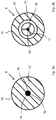
- The invention shall be elaborated on with reference to a number of embodiments by way of example that are depicted in the accompanying drawings. Shown in:
-
Figures 1A and1B respectively are a vertical cross-sectional view through a part of an example of a system according to the invention and a top view; -
Figure 2 is a top view of a part of another example of a system according to the invention; and -
Figures 3A and 3B in cross-sectional views are two examples of a roller for a system according to the invention. - The
system 1 depicted inFigures 1A and1B comprises acasing 2 taken up in anunderground 100, which casing defines areceiving space 5. Thecasing 2 has abottom wall 3 with ahole 19 that is provided with a tapered edge, whichhole 19 in this example is square, and a top opening 4, that can be closed off by means of a removable,multi-part cover 20, at the level of thesurface 101 above ground. - The
receiving space 5 has a centre-line Y, which in this example is vertical. In the receiving space 5 a number ofrollers 6 have been provided, that are freely rotatable aroundaxes 11 and that have a right circular cylindrical contact surface 12 (when) in an unloaded state. The rotational central axes of therollers 6 lie in a plane that is transverse with respect to the centre-line Y. As can be seen inFigure 1B , there are fourrollers 6, which are supported with theiraxis ends 15 in holdingmembers casing 2. Therollers 6 delimit apassageway 16. Thehole 19 forms a first pole holder, therollers 6 form a second pole holder, at a distance h above the first pole holder. - In
Figure 1A , for illustrative reasons a pole 7 is shown before it has reached its (end) position in the receivingspace 5. The pole 7 has alower part 7a that is meant for being taken up in the receiving space. Thelower part 7a has alower end surface 8, that is provided with a downward tapered protrusion 9, in this example with a square cross-section. The pole 7 is suitable for supporting a surface (i.e. above the ground) structure, that is not depicted, such as play equipment, for example a see-saw. - The thickness of the
lower part 7a of the pole 7, in this case equal to the side of the outer surface thereof, has a size T. The shortest distance S between the facing parts of the contact surfaces 12 is in an unloaded, free state of therollers 6 less than T. This aspect is depicted with some exaggeration inFigure 1B . This difference in size between S and T is accomodated by the elastic, resilient impressibility of the material of which thecontact surface 12 is a part. - In this way when placing the pole 7, the
lower part 7a can be lowered from above, through the opening 4, in the direction A1 with itsbottom plane 8 right up against therollers 6. Eventually with the application of light pressure, the lower end of the pole 7 can come between therollers 6, in thepassageway 16, whereby therollers 12 roll along in the directions B1. The contact surfaces 12 can thereby deviate, in a resilient manner, in outer directions C, till a mutual shortest distance T. With further lowering of the pole 7, thelower part 7a rolls with its outer surface over therollers 6, till the protrusion 9 is taken up fittingly in thehole 19. Thebottom plane 8 then rests on thebottom wall 3. The pole is then held by thefirst pole holder parts 8, 9 and (by) the second pole holder withrollers 6 of which the resilient contact surfaces persistently engage with the sides of the pole, at a distance h above the first pole holder. By this the pole 7 is held in its direction by way of a resilient clamping. - Where in the system of
Figures 1A and1B the sides of the pole 7 lie flat right against therollers 6, in the embodiment ofFigure 2 the area of engagement is more limited, whereby thelower part 7a of the pole has a circular cross-section and threerollers 6 have been arranged according to an equilateral triangle. The impression of the contact surfaces 12 in the directions 1C is more concave, in accordance with the curvature of the surface of thelower part 7a of the pole. - The resilient compliability of the surface of the
rollers 6 relative to the surface of the pole 7 can be achieved in different ways. The axis ends 15 in the directions C can be mounted resiliently on theend holding members Figures 3A and 3B . InFigure 3A it is about aroller 6 of an almost massive elasticartificial material 13, with ahole 14 for theaxis 11. InFigure 3B it is about a ring of an elasticartificial material 13, mounted on asteel casing 17 in which theaxis 11 is fixed byspokes 18. The axis ends 15 hereby can be taken up and held in place in holdingmembers - The freely rotatable rollers are also favourable when removing the pole, because they form a roller support in the opposite direction B2 for the upwardly moving pole.
- In the case of the rollers being staggered in the (longitudinal) direction of the pole, the passageway is determined by the projection of the rollers on a projection plane perpendicular to the pole. With a vertical pole that is a horizontal projection plane.
- The invention is in no way limited to the embodiments described in the description and shown in the drawings. The foregoing description is given for illustrating the workings of preferred embodiments of the invention, and not to limit the scope of the invention. Starting from the foregoing description it will be clear to a skilled person that there are many variations that will fall under the intent and the scope of the present invention. E.g. the skilled person will consider the application of an impact layer of a relatively soft material on the contact surface of the pole and/or on the contact surface of the one or more rollers in order to improve user safety. Variations of the parts described in the description and shown in the drawings are possible. These can be utilized separately in different embodiments of the invention(s). Parts of different examples that have been given can be combined with each other.
Claims (23)
- A system for placing of structures on an underground, comprising a pole for supporting the structure and an elongate receiving space taken up in the underground, in particular an elongate receiving space with a vertical-directional component, in particular a substantially vertically directed receiving space, for receiving a lower part of the pole, whereby the receiving space has a central axis and is provided with a first pole holder and a second pole holder which are spaced apart (as seen) in the direction of the central axis, characterized in that the second pole holder lies above the first pole holder and the first and second pole holders are furnished in accordance with the pole for keeping the pole in the desired orientation, whereby the second pole holder determines a passageway for the pole and comprises one or more rollers, which one or more rollers have contact surfaces for making contact with the pole and which are rotatable around their respective rotational central axes that lie in a respective plane that lies transversally with respect to the central axis of the receiving space.
- A system according to clsim 1, whereby the second pole holder comprises three or more rollers, that are positioned for engaging the pole at positions that are spaced apart (as seen) in the circumferential direction of the pole, at regularly spaced apart positions.
- A system according to claim 1 or 2, whereby in the case of multiple rollers the rotational central axes thereof lie in or lie at least near one plane that is transversal with respect to the central axis.
- A system according to any of the preceding claims, whereby the contact surface of at least one of the one or more rollers is elastically moveable in directions along a radial with respect to the central axis.
- A system according to any of the preceding claims, whereby the contact surface of at least one of the one or more rollers is elastically impressible.
- A system according to claim 5, whereby the contat surface is made of an elastically impressible material.
- A system according to claim 4, whereby the at least one or more rollers are mounted resiliently in the receiving space.
- A system according to any of the preceding claims, whereby the pole is provided with an elastic lining, in particular in the form of a teflon cuff around a part of the pole that will guided along the rollers.
- A system according to any of the preceding claims, whereby the contact surface of the one or more rollers is provided with an elastic lining, in particular a strip or sleeve of teflon or a comparable material.
- A system according to claim 5 or 6, whereby the shapes and sizes of the passageway and the lower part of the pole are such relative to each other that the one or more rollers in the passageway exert a clamping force on the pole.
- A system according to claim 10, whereby the pole when present in the passageway has a cross-section there that, when seen in projection on a projection plane that is perpendicular with respect to the pole, in particular a horizontal projection plane, extends beyond the projection of the passageway on the same projection plane at the location of the projection on that projection plane of at least one of the one or more rollers.
- A system according to claim 11, whereby the passageway is delimited by three rollers and the contact surfaces of these three rollers form a smallest imaginary circle, whereby the cross-section in the lower part of the pole is circular with a diameter greater than that of the circle.
- A system according to claim 11, whereby the passageway is delimited by four rollers that in pairs face each other, whereby the cross-section in the lower part of the pole is circular, whereby the diameter of the circle is greater than the distance between the facing contact surfaces of two rollers that lie opposite to one another.
- A system according to claim 11, whereby the passageway is delimited by four rollers that in pairs face each other, whereby the cross-section in the lower part of the pole is rectangular, whereby a side of the rectangle is greater than the distance between the facing contact surfaces of two rollers that lie opposite to one another.
- A system according to any of the preceding claims, whereby the first pole holder is provided with a first coupling member and the pole at its lower end is provided with a second coupling member, whereby the first and the second coupling members are connectable to each other for holding the lower end in its position in the horizontal plane, preferably also in a downward direction.
- A system according to claim 15, whereby the first coupling member and the second coupling member form a tapered pin-hole coupling.
- A system according to claim 16, whereby the second coupling member is provided at the bottom surface of the lower end of the pole, preferably in the form of a downward protrusion.
- A system according to any of claims 15,16 and 17, whereby the first coupling member and the second coupling member are also connectable to each other for holding the pole against rotating around the central axis.
- A system according to any of the preceding claims, whereby the second pole holder lies near the surface (ground level).
- A system according to any of the preceding claims, whereby the first pole holder lies near the bottom of the receiving space.
- A system according to any of the preceding claims, whereby the receiving space is formed by a casing placed in the underground
- An arrangement of a number of systems according to any of the preceding claims and a surface structure, whereby the poles jointly bear the surface structure.
- An arrangement according to claim 20, whereby the surface structure forms a recreational facility.
Applications Claiming Priority (1)
| Application Number | Priority Date | Filing Date | Title |
|---|---|---|---|
| NL2017084A NL2017084B1 (en) | 2016-07-01 | 2016-07-01 | SYSTEM FOR PLACING CONSTRUCTIONS ON A BACKGROUND |
Publications (2)
| Publication Number | Publication Date |
|---|---|
| EP3263804A1 true EP3263804A1 (en) | 2018-01-03 |
| EP3263804B1 EP3263804B1 (en) | 2018-10-03 |
Family
ID=56852367
Family Applications (1)
| Application Number | Title | Priority Date | Filing Date |
|---|---|---|---|
| EP17176978.9A Active EP3263804B1 (en) | 2016-07-01 | 2017-06-20 | A system for placing of structures on an underground |
Country Status (3)
| Country | Link |
|---|---|
| EP (1) | EP3263804B1 (en) |
| DK (1) | DK3263804T3 (en) |
| NL (1) | NL2017084B1 (en) |
Citations (4)
| Publication number | Priority date | Publication date | Assignee | Title |
|---|---|---|---|---|
| DE2755269A1 (en) * | 1977-12-12 | 1979-06-13 | Moenninghoff Gmbh & Co Kg | Transportable signpost base post insertion channel - has roller cage in widened top area for ease of insertion |
| EP0201645A2 (en) * | 1985-05-10 | 1986-11-20 | Chu Associates Inc | Telescoping lightweight antenna tower assembly and the like |
| WO1995014147A1 (en) * | 1993-11-19 | 1995-05-26 | Lindberg Goete | A ground anchorage device with a post belonging thereto |
| WO2015190981A1 (en) * | 2014-06-12 | 2015-12-17 | Northcone Ab | Pole arrangement |
-
2016
- 2016-07-01 NL NL2017084A patent/NL2017084B1/en not_active IP Right Cessation
-
2017
- 2017-06-20 DK DK17176978.9T patent/DK3263804T3/en active
- 2017-06-20 EP EP17176978.9A patent/EP3263804B1/en active Active
Patent Citations (4)
| Publication number | Priority date | Publication date | Assignee | Title |
|---|---|---|---|---|
| DE2755269A1 (en) * | 1977-12-12 | 1979-06-13 | Moenninghoff Gmbh & Co Kg | Transportable signpost base post insertion channel - has roller cage in widened top area for ease of insertion |
| EP0201645A2 (en) * | 1985-05-10 | 1986-11-20 | Chu Associates Inc | Telescoping lightweight antenna tower assembly and the like |
| WO1995014147A1 (en) * | 1993-11-19 | 1995-05-26 | Lindberg Goete | A ground anchorage device with a post belonging thereto |
| WO2015190981A1 (en) * | 2014-06-12 | 2015-12-17 | Northcone Ab | Pole arrangement |
Also Published As
| Publication number | Publication date |
|---|---|
| EP3263804B1 (en) | 2018-10-03 |
| NL2017084B1 (en) | 2018-01-19 |
| NL2017084A (en) | 2018-01-09 |
| DK3263804T3 (en) | 2019-01-21 |
Similar Documents
| Publication | Publication Date | Title |
|---|---|---|
| US3954269A (en) | Indiciaed ball having loose interior weight | |
| US8393081B2 (en) | Method for filling a ball roller bearing with roll bodies as well as a ball roller bearing filled according to the method | |
| EP3263804B1 (en) | A system for placing of structures on an underground | |
| EP1770294A4 (en) | Tapered roller bearing | |
| US10173115B2 (en) | Adjustable training golf tee | |
| WO2018112324A3 (en) | Interbody implant with concave profiled nose | |
| KR101956319B1 (en) | Hard-rolling roller | |
| HK1245039A1 (en) | Resting device | |
| CN105629697B (en) | Stake in flexibility | |
| EP1647727A3 (en) | Tapered roller bearing | |
| RU163123U1 (en) | DEVICE FOR INSTALLING SUPPORTS OF AIR LINES AND CONTACT NETWORK | |
| US9709098B2 (en) | Roller bearing spring clip | |
| US9228755B2 (en) | Vent and cover plate assembly for dust-free workshop floor | |
| US20150023624A1 (en) | Slewing bearing with a through-hole and plug | |
| JP4489097B2 (en) | Seismic isolation device | |
| KR101773462B1 (en) | The flag pole | |
| JP5107775B2 (en) | Seismic isolation bearing structure | |
| US1643982A (en) | Bearing | |
| CN220505611U (en) | Flattening ring shaft sleeve | |
| JP5649259B1 (en) | Steel ball seismic isolation device. | |
| JP4032371B2 (en) | Pole support | |
| US20100122510A1 (en) | Cage spacer with roller wheel | |
| US20190153745A1 (en) | Swivel hub for tent poles | |
| CN201347979Y (en) | Double-row arc surface roller bearing | |
| EP2946688A1 (en) | An apparatus for carrying and storing pipes |
Legal Events
| Date | Code | Title | Description |
|---|---|---|---|
| PUAI | Public reference made under article 153(3) epc to a published international application that has entered the european phase |
Free format text: ORIGINAL CODE: 0009012 |
|
| STAA | Information on the status of an ep patent application or granted ep patent |
Free format text: STATUS: REQUEST FOR EXAMINATION WAS MADE |
|
| 17P | Request for examination filed |
Effective date: 20170620 |
|
| AK | Designated contracting states |
Kind code of ref document: A1 Designated state(s): AL AT BE BG CH CY CZ DE DK EE ES FI FR GB GR HR HU IE IS IT LI LT LU LV MC MK MT NL NO PL PT RO RS SE SI SK SM TR |
|
| AX | Request for extension of the european patent |
Extension state: BA ME |
|
| GRAP | Despatch of communication of intention to grant a patent |
Free format text: ORIGINAL CODE: EPIDOSNIGR1 |
|
| STAA | Information on the status of an ep patent application or granted ep patent |
Free format text: STATUS: GRANT OF PATENT IS INTENDED |
|
| INTG | Intention to grant announced |
Effective date: 20180426 |
|
| RBV | Designated contracting states (corrected) |
Designated state(s): AL AT BE BG CH CY CZ DE DK EE ES FI FR GB GR HR HU IE IS IT LI LT LU LV MC MK MT NL NO PL PT RO RS SE SI SK SM TR |
|
| GRAS | Grant fee paid |
Free format text: ORIGINAL CODE: EPIDOSNIGR3 |
|
| GRAA | (expected) grant |
Free format text: ORIGINAL CODE: 0009210 |
|
| STAA | Information on the status of an ep patent application or granted ep patent |
Free format text: STATUS: THE PATENT HAS BEEN GRANTED |
|
| AK | Designated contracting states |
Kind code of ref document: B1 Designated state(s): AL AT BE BG CH CY CZ DE DK EE ES FI FR GB GR HR HU IE IS IT LI LT LU LV MC MK MT NL NO PL PT RO RS SE SI SK SM TR |
|
| REG | Reference to a national code |
Ref country code: GB Ref legal event code: FG4D |
|
| REG | Reference to a national code |
Ref country code: CH Ref legal event code: EP Ref country code: AT Ref legal event code: REF Ref document number: 1048761 Country of ref document: AT Kind code of ref document: T Effective date: 20181015 |
|
| REG | Reference to a national code |
Ref country code: IE Ref legal event code: FG4D |
|
| REG | Reference to a national code |
Ref country code: NL Ref legal event code: FP |
|
| REG | Reference to a national code |
Ref country code: DE Ref legal event code: R096 Ref document number: 602017000577 Country of ref document: DE |
|
| REG | Reference to a national code |
Ref country code: DK Ref legal event code: T3 Effective date: 20190115 |
|
| REG | Reference to a national code |
Ref country code: SE Ref legal event code: TRGR |
|
| REG | Reference to a national code |
Ref country code: LT Ref legal event code: MG4D |
|
| REG | Reference to a national code |
Ref country code: AT Ref legal event code: MK05 Ref document number: 1048761 Country of ref document: AT Kind code of ref document: T Effective date: 20181003 |
|
| PG25 | Lapsed in a contracting state [announced via postgrant information from national office to epo] |
Ref country code: IS Free format text: LAPSE BECAUSE OF FAILURE TO SUBMIT A TRANSLATION OF THE DESCRIPTION OR TO PAY THE FEE WITHIN THE PRESCRIBED TIME-LIMIT Effective date: 20190203 Ref country code: FI Free format text: LAPSE BECAUSE OF FAILURE TO SUBMIT A TRANSLATION OF THE DESCRIPTION OR TO PAY THE FEE WITHIN THE PRESCRIBED TIME-LIMIT Effective date: 20181003 Ref country code: BG Free format text: LAPSE BECAUSE OF FAILURE TO SUBMIT A TRANSLATION OF THE DESCRIPTION OR TO PAY THE FEE WITHIN THE PRESCRIBED TIME-LIMIT Effective date: 20190103 Ref country code: HR Free format text: LAPSE BECAUSE OF FAILURE TO SUBMIT A TRANSLATION OF THE DESCRIPTION OR TO PAY THE FEE WITHIN THE PRESCRIBED TIME-LIMIT Effective date: 20181003 Ref country code: LV Free format text: LAPSE BECAUSE OF FAILURE TO SUBMIT A TRANSLATION OF THE DESCRIPTION OR TO PAY THE FEE WITHIN THE PRESCRIBED TIME-LIMIT Effective date: 20181003 Ref country code: ES Free format text: LAPSE BECAUSE OF FAILURE TO SUBMIT A TRANSLATION OF THE DESCRIPTION OR TO PAY THE FEE WITHIN THE PRESCRIBED TIME-LIMIT Effective date: 20181003 Ref country code: AT Free format text: LAPSE BECAUSE OF FAILURE TO SUBMIT A TRANSLATION OF THE DESCRIPTION OR TO PAY THE FEE WITHIN THE PRESCRIBED TIME-LIMIT Effective date: 20181003 Ref country code: PL Free format text: LAPSE BECAUSE OF FAILURE TO SUBMIT A TRANSLATION OF THE DESCRIPTION OR TO PAY THE FEE WITHIN THE PRESCRIBED TIME-LIMIT Effective date: 20181003 Ref country code: LT Free format text: LAPSE BECAUSE OF FAILURE TO SUBMIT A TRANSLATION OF THE DESCRIPTION OR TO PAY THE FEE WITHIN THE PRESCRIBED TIME-LIMIT Effective date: 20181003 Ref country code: NO Free format text: LAPSE BECAUSE OF FAILURE TO SUBMIT A TRANSLATION OF THE DESCRIPTION OR TO PAY THE FEE WITHIN THE PRESCRIBED TIME-LIMIT Effective date: 20190103 Ref country code: CZ Free format text: LAPSE BECAUSE OF FAILURE TO SUBMIT A TRANSLATION OF THE DESCRIPTION OR TO PAY THE FEE WITHIN THE PRESCRIBED TIME-LIMIT Effective date: 20181003 |
|
| PG25 | Lapsed in a contracting state [announced via postgrant information from national office to epo] |
Ref country code: PT Free format text: LAPSE BECAUSE OF FAILURE TO SUBMIT A TRANSLATION OF THE DESCRIPTION OR TO PAY THE FEE WITHIN THE PRESCRIBED TIME-LIMIT Effective date: 20190203 Ref country code: RS Free format text: LAPSE BECAUSE OF FAILURE TO SUBMIT A TRANSLATION OF THE DESCRIPTION OR TO PAY THE FEE WITHIN THE PRESCRIBED TIME-LIMIT Effective date: 20181003 Ref country code: GR Free format text: LAPSE BECAUSE OF FAILURE TO SUBMIT A TRANSLATION OF THE DESCRIPTION OR TO PAY THE FEE WITHIN THE PRESCRIBED TIME-LIMIT Effective date: 20190104 Ref country code: AL Free format text: LAPSE BECAUSE OF FAILURE TO SUBMIT A TRANSLATION OF THE DESCRIPTION OR TO PAY THE FEE WITHIN THE PRESCRIBED TIME-LIMIT Effective date: 20181003 |
|
| REG | Reference to a national code |
Ref country code: DE Ref legal event code: R097 Ref document number: 602017000577 Country of ref document: DE |
|
| REG | Reference to a national code |
Ref country code: CH Ref legal event code: NV Representative=s name: REUTELER AND CIE S.A., CH |
|
| PG25 | Lapsed in a contracting state [announced via postgrant information from national office to epo] |
Ref country code: IT Free format text: LAPSE BECAUSE OF FAILURE TO SUBMIT A TRANSLATION OF THE DESCRIPTION OR TO PAY THE FEE WITHIN THE PRESCRIBED TIME-LIMIT Effective date: 20181003 |
|
| PLBE | No opposition filed within time limit |
Free format text: ORIGINAL CODE: 0009261 |
|
| STAA | Information on the status of an ep patent application or granted ep patent |
Free format text: STATUS: NO OPPOSITION FILED WITHIN TIME LIMIT |
|
| PG25 | Lapsed in a contracting state [announced via postgrant information from national office to epo] |
Ref country code: EE Free format text: LAPSE BECAUSE OF FAILURE TO SUBMIT A TRANSLATION OF THE DESCRIPTION OR TO PAY THE FEE WITHIN THE PRESCRIBED TIME-LIMIT Effective date: 20181003 Ref country code: SM Free format text: LAPSE BECAUSE OF FAILURE TO SUBMIT A TRANSLATION OF THE DESCRIPTION OR TO PAY THE FEE WITHIN THE PRESCRIBED TIME-LIMIT Effective date: 20181003 Ref country code: RO Free format text: LAPSE BECAUSE OF FAILURE TO SUBMIT A TRANSLATION OF THE DESCRIPTION OR TO PAY THE FEE WITHIN THE PRESCRIBED TIME-LIMIT Effective date: 20181003 Ref country code: SK Free format text: LAPSE BECAUSE OF FAILURE TO SUBMIT A TRANSLATION OF THE DESCRIPTION OR TO PAY THE FEE WITHIN THE PRESCRIBED TIME-LIMIT Effective date: 20181003 |
|
| 26N | No opposition filed |
Effective date: 20190704 |
|
| PG25 | Lapsed in a contracting state [announced via postgrant information from national office to epo] |
Ref country code: MC Free format text: LAPSE BECAUSE OF FAILURE TO SUBMIT A TRANSLATION OF THE DESCRIPTION OR TO PAY THE FEE WITHIN THE PRESCRIBED TIME-LIMIT Effective date: 20181003 |
|
| PG25 | Lapsed in a contracting state [announced via postgrant information from national office to epo] |
Ref country code: TR Free format text: LAPSE BECAUSE OF FAILURE TO SUBMIT A TRANSLATION OF THE DESCRIPTION OR TO PAY THE FEE WITHIN THE PRESCRIBED TIME-LIMIT Effective date: 20181003 |
|
| PG25 | Lapsed in a contracting state [announced via postgrant information from national office to epo] |
Ref country code: IE Free format text: LAPSE BECAUSE OF NON-PAYMENT OF DUE FEES Effective date: 20190620 |
|
| PG25 | Lapsed in a contracting state [announced via postgrant information from national office to epo] |
Ref country code: LU Free format text: LAPSE BECAUSE OF NON-PAYMENT OF DUE FEES Effective date: 20190620 |
|
| PG25 | Lapsed in a contracting state [announced via postgrant information from national office to epo] |
Ref country code: CY Free format text: LAPSE BECAUSE OF FAILURE TO SUBMIT A TRANSLATION OF THE DESCRIPTION OR TO PAY THE FEE WITHIN THE PRESCRIBED TIME-LIMIT Effective date: 20181003 |
|
| PG25 | Lapsed in a contracting state [announced via postgrant information from national office to epo] |
Ref country code: MT Free format text: LAPSE BECAUSE OF FAILURE TO SUBMIT A TRANSLATION OF THE DESCRIPTION OR TO PAY THE FEE WITHIN THE PRESCRIBED TIME-LIMIT Effective date: 20181003 Ref country code: HU Free format text: LAPSE BECAUSE OF FAILURE TO SUBMIT A TRANSLATION OF THE DESCRIPTION OR TO PAY THE FEE WITHIN THE PRESCRIBED TIME-LIMIT; INVALID AB INITIO Effective date: 20170620 |
|
| PG25 | Lapsed in a contracting state [announced via postgrant information from national office to epo] |
Ref country code: SI Free format text: LAPSE BECAUSE OF FAILURE TO SUBMIT A TRANSLATION OF THE DESCRIPTION OR TO PAY THE FEE WITHIN THE PRESCRIBED TIME-LIMIT Effective date: 20181003 |
|
| PG25 | Lapsed in a contracting state [announced via postgrant information from national office to epo] |
Ref country code: MK Free format text: LAPSE BECAUSE OF FAILURE TO SUBMIT A TRANSLATION OF THE DESCRIPTION OR TO PAY THE FEE WITHIN THE PRESCRIBED TIME-LIMIT Effective date: 20181003 |
|
| PGFP | Annual fee paid to national office [announced via postgrant information from national office to epo] |
Ref country code: DE Payment date: 20250619 Year of fee payment: 9 |
|
| PGFP | Annual fee paid to national office [announced via postgrant information from national office to epo] |
Ref country code: DK Payment date: 20250613 Year of fee payment: 9 Ref country code: GB Payment date: 20250618 Year of fee payment: 9 |
|
| PGFP | Annual fee paid to national office [announced via postgrant information from national office to epo] |
Ref country code: NL Payment date: 20250623 Year of fee payment: 9 |
|
| PGFP | Annual fee paid to national office [announced via postgrant information from national office to epo] |
Ref country code: FR Payment date: 20250618 Year of fee payment: 9 |
|
| PGFP | Annual fee paid to national office [announced via postgrant information from national office to epo] |
Ref country code: SE Payment date: 20250613 Year of fee payment: 9 |
|
| PGFP | Annual fee paid to national office [announced via postgrant information from national office to epo] |
Ref country code: BE Payment date: 20250623 Year of fee payment: 9 |
|
| PGFP | Annual fee paid to national office [announced via postgrant information from national office to epo] |
Ref country code: CH Payment date: 20250701 Year of fee payment: 9 |