EP3263485A1 - Packaging container - Google Patents
Packaging container Download PDFInfo
- Publication number
- EP3263485A1 EP3263485A1 EP16755019.3A EP16755019A EP3263485A1 EP 3263485 A1 EP3263485 A1 EP 3263485A1 EP 16755019 A EP16755019 A EP 16755019A EP 3263485 A1 EP3263485 A1 EP 3263485A1
- Authority
- EP
- European Patent Office
- Prior art keywords
- engaging
- funnel part
- packaging container
- body portion
- layer film
- Prior art date
- Legal status (The legal status is an assumption and is not a legal conclusion. Google has not performed a legal analysis and makes no representation as to the accuracy of the status listed.)
- Granted
Links
Images





Classifications
-
- B—PERFORMING OPERATIONS; TRANSPORTING
- B65—CONVEYING; PACKING; STORING; HANDLING THIN OR FILAMENTARY MATERIAL
- B65D—CONTAINERS FOR STORAGE OR TRANSPORT OF ARTICLES OR MATERIALS, e.g. BAGS, BARRELS, BOTTLES, BOXES, CANS, CARTONS, CRATES, DRUMS, JARS, TANKS, HOPPERS, FORWARDING CONTAINERS; ACCESSORIES, CLOSURES, OR FITTINGS THEREFOR; PACKAGING ELEMENTS; PACKAGES
- B65D47/00—Closures with filling and discharging, or with discharging, devices
- B65D47/04—Closures with discharging devices other than pumps
- B65D47/06—Closures with discharging devices other than pumps with pouring spouts or tubes; with discharge nozzles or passages
- B65D47/12—Closures with discharging devices other than pumps with pouring spouts or tubes; with discharge nozzles or passages having removable closures
- B65D47/14—Closures with discharging devices other than pumps with pouring spouts or tubes; with discharge nozzles or passages having removable closures and closure-retaining means
-
- B—PERFORMING OPERATIONS; TRANSPORTING
- B65—CONVEYING; PACKING; STORING; HANDLING THIN OR FILAMENTARY MATERIAL
- B65D—CONTAINERS FOR STORAGE OR TRANSPORT OF ARTICLES OR MATERIALS, e.g. BAGS, BARRELS, BOTTLES, BOXES, CANS, CARTONS, CRATES, DRUMS, JARS, TANKS, HOPPERS, FORWARDING CONTAINERS; ACCESSORIES, CLOSURES, OR FITTINGS THEREFOR; PACKAGING ELEMENTS; PACKAGES
- B65D77/00—Packages formed by enclosing articles or materials in preformed containers, e.g. boxes, cartons, sacks or bags
- B65D77/10—Container closures formed after filling
- B65D77/20—Container closures formed after filling by applying separate lids or covers, i.e. flexible membrane or foil-like covers
- B65D77/2024—Container closures formed after filling by applying separate lids or covers, i.e. flexible membrane or foil-like covers the cover being welded or adhered to the container
- B65D77/2028—Means for opening the cover other than, or in addition to, a pull tab
- B65D77/2032—Means for opening the cover other than, or in addition to, a pull tab by peeling or tearing the cover from the container
- B65D77/2044—Means for opening the cover other than, or in addition to, a pull tab by peeling or tearing the cover from the container whereby a layer of the container or cover fails, e.g. cohesive failure
- B65D77/2048—Means for opening the cover other than, or in addition to, a pull tab by peeling or tearing the cover from the container whereby a layer of the container or cover fails, e.g. cohesive failure whereby part of the container or cover has been weakened, e.g. perforated or precut
- B65D77/2056—Means for opening the cover other than, or in addition to, a pull tab by peeling or tearing the cover from the container whereby a layer of the container or cover fails, e.g. cohesive failure whereby part of the container or cover has been weakened, e.g. perforated or precut the cover being weakened
-
- B—PERFORMING OPERATIONS; TRANSPORTING
- B65—CONVEYING; PACKING; STORING; HANDLING THIN OR FILAMENTARY MATERIAL
- B65D—CONTAINERS FOR STORAGE OR TRANSPORT OF ARTICLES OR MATERIALS, e.g. BAGS, BARRELS, BOTTLES, BOXES, CANS, CARTONS, CRATES, DRUMS, JARS, TANKS, HOPPERS, FORWARDING CONTAINERS; ACCESSORIES, CLOSURES, OR FITTINGS THEREFOR; PACKAGING ELEMENTS; PACKAGES
- B65D77/00—Packages formed by enclosing articles or materials in preformed containers, e.g. boxes, cartons, sacks or bags
- B65D77/10—Container closures formed after filling
- B65D77/20—Container closures formed after filling by applying separate lids or covers, i.e. flexible membrane or foil-like covers
- B65D77/2024—Container closures formed after filling by applying separate lids or covers, i.e. flexible membrane or foil-like covers the cover being welded or adhered to the container
- B65D77/2068—Means for reclosing the cover after its first opening
- B65D77/2072—Mechanical means
- B65D77/2088—Mechanical means attached to the cover
- B65D77/2092—Mechanical means attached to the cover the means being a part initially broken from the container
-
- B—PERFORMING OPERATIONS; TRANSPORTING
- B65—CONVEYING; PACKING; STORING; HANDLING THIN OR FILAMENTARY MATERIAL
- B65D—CONTAINERS FOR STORAGE OR TRANSPORT OF ARTICLES OR MATERIALS, e.g. BAGS, BARRELS, BOTTLES, BOXES, CANS, CARTONS, CRATES, DRUMS, JARS, TANKS, HOPPERS, FORWARDING CONTAINERS; ACCESSORIES, CLOSURES, OR FITTINGS THEREFOR; PACKAGING ELEMENTS; PACKAGES
- B65D83/00—Containers or packages with special means for dispensing contents
- B65D83/06—Containers or packages with special means for dispensing contents for dispensing powdered or granular material
-
- B—PERFORMING OPERATIONS; TRANSPORTING
- B65—CONVEYING; PACKING; STORING; HANDLING THIN OR FILAMENTARY MATERIAL
- B65D—CONTAINERS FOR STORAGE OR TRANSPORT OF ARTICLES OR MATERIALS, e.g. BAGS, BARRELS, BOTTLES, BOXES, CANS, CARTONS, CRATES, DRUMS, JARS, TANKS, HOPPERS, FORWARDING CONTAINERS; ACCESSORIES, CLOSURES, OR FITTINGS THEREFOR; PACKAGING ELEMENTS; PACKAGES
- B65D2231/00—Means for facilitating the complete expelling of the contents
- B65D2231/005—Means for facilitating the complete expelling of the contents the container being rigid
- B65D2231/007—Funnels or the like
-
- B—PERFORMING OPERATIONS; TRANSPORTING
- B65—CONVEYING; PACKING; STORING; HANDLING THIN OR FILAMENTARY MATERIAL
- B65D—CONTAINERS FOR STORAGE OR TRANSPORT OF ARTICLES OR MATERIALS, e.g. BAGS, BARRELS, BOTTLES, BOXES, CANS, CARTONS, CRATES, DRUMS, JARS, TANKS, HOPPERS, FORWARDING CONTAINERS; ACCESSORIES, CLOSURES, OR FITTINGS THEREFOR; PACKAGING ELEMENTS; PACKAGES
- B65D3/00—Rigid or semi-rigid containers having bodies or peripheral walls of curved or partially-curved cross-section made by winding or bending paper without folding along defined lines
- B65D3/10—Rigid or semi-rigid containers having bodies or peripheral walls of curved or partially-curved cross-section made by winding or bending paper without folding along defined lines characterised by form of integral or permanently secured end closure
- B65D3/12—Flanged discs permanently secured, e.g. by adhesives or by heat-sealing
-
- B—PERFORMING OPERATIONS; TRANSPORTING
- B65—CONVEYING; PACKING; STORING; HANDLING THIN OR FILAMENTARY MATERIAL
- B65D—CONTAINERS FOR STORAGE OR TRANSPORT OF ARTICLES OR MATERIALS, e.g. BAGS, BARRELS, BOTTLES, BOXES, CANS, CARTONS, CRATES, DRUMS, JARS, TANKS, HOPPERS, FORWARDING CONTAINERS; ACCESSORIES, CLOSURES, OR FITTINGS THEREFOR; PACKAGING ELEMENTS; PACKAGES
- B65D77/00—Packages formed by enclosing articles or materials in preformed containers, e.g. boxes, cartons, sacks or bags
- B65D77/22—Details
- B65D77/30—Opening or contents-removing devices added or incorporated during filling or closing of containers
- B65D77/38—Weakened closure seams
Definitions
- the present invention relates to a packaging container that facilitates transfer of fluid contents such as powdered, granular or liquid contents into other containers.
- Packaging containers disclosed in PTLs 1 to 4 are known as packaging containers which facilitate refill of powdered or granular contents such as instant coffee into a storage container or a tank of a coffee machine.
- Fig. 10 shows a longitudinal sectional view of a packaging container 900 according to an example of such a packaging container.
- the packaging container 900 includes a cylindrical container body 920, a funnel part 930 fixed to an inner wall of the container body 920, and a sealing lid 960.
- the inside of the container body 920 is filled with contents 950 such as powders, and the opening portion of the container body 920 is sealed by the sealing lid 960.
- the sealing lid 960 has a lower layer film 961 and an upper layer film 962 which are removably laminated, and the lower layer film 961 includes cut lines which radially extend from the center of the lower layer film 961.
- the sealing lid 960 is sealed to the opening portion of the container body 920 in the state that it is in contact with a narrow opening end 931 of the funnel part.
- a tab 905 is pulled up to separate the upper layer film 962 from the lower layer film 961, and then the lower layer film 961 is pushed while being applied to the opening portion of a container to be refilled to break the lower layer film 961 along the cut lines. Accordingly, the contents 950 can be easily refilled into the container through the funnel part 930.
- the funnel part 930 is fixed to the container body 920 by, for example, inserting the funnel part 930 into the container body 920 for positioning, followed by high-frequency melting and bonding a portion where the inner wall of the container body 920 is in contact with the funnel part 930.
- the funnel part 930 is adhered and fixed to the container body 920 by being inserted into the container body 920 in the state that a portion of the inner wall of the container body 920 to which the funnel part 930 is to be fixed is heated and melted in advance.
- the funnel part 930 can be inserted into a position lower than a position to which the funnel part 930 is to be fixed. Hence, it is difficult to accurately insert the funnel part 930 to the position to which the funnel part 930 is to be fixed, and maintain the position until the funnel part 930 is fixed to the container body 920. Such a positioning with high accuracy requires a complex and expensive device and apparatus, thus resulting in high manufacturing cost.
- An object of the present invention is to facilitate positioning of a portion to which a funnel-shaped spout is to be attached and reduce manufacturing costs for a packaging container in which the funnel-shaped spout is attached to the container body.
- An aspect of the present invention is a packaging container including: a container body having a body portion provided with an engaging wall, and a bottom portion provided at the first end of the body portion; a funnel part having a funnel shape inserted into the body portion, and a wide opening end thereof is restricted from being moved toward at least the first end; and a sealing lid sealed to an opening portion which serves as a second end of the body portion while being in contact with a narrow opening end of the funnel part to seal the container body.
- a packaging container in which a funnel-shaped spout is attached to the container body positioning of a portion to which the funnel-shaped spout is to be attached is facilitated, and manufacturing costs are reduced.
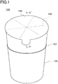
- Fig. 1 is a perspective view of a packaging container 100
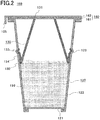
- Fig. 2 is a longitudinal sectional view of the packaging container 100 taken along the line A-A' of Fig. 1 .
- the packaging container 100 includes a cylindrical container body 120 having a bottom portion and an opening portion, a funnel part 130 and a sealing lid 160. Inside the container body 120 is filled with contents 150 such as powders, and the opening portion of the container body 120 is sealed by a sealing lid 160.
- the container body 120 includes a bottom portion 121 and a body portion 122.
- the bottom portion 121 is attached to the first end of the body portion 122.
- the body portion 122 is in a tapered shape in which the diameter is gradually increased from the bottom portion 121 toward the second end which serves as an opening portion of the container body 120.
- an engaging groove 123 is projected outward, which structures a recessed portion in the body portion 122 is formed at a predetermined portion such that it surrounds the body portion 122.
- the funnel part 130 is in a funnel shape having a narrow opening end and a wide opening end.
- the funnel part 130 has a wide opening end 132 in which an engaging portion 134 having a projection 133 projected outward is formed.
- the projection 133 is fitted into the engaging groove 123.
- the sealing lid 160 includes a lower layer film 161 which is sealed to the opening portion of the container body 120, and an upper layer film 162 laminated on the outer surface of the lower layer film 161 such that it can be separated therefrom.
- the lower layer film 161 is provided with radial cut lines 199 such as a perforation, and are torn by being pushed by a container to be refilled when in use.
- the upper layer film 162 is provided to protect the cut lines 199 formed on the lower layer film 161, and to ensure the sealing ability of the packaging container 100, and is separated from the lower layer film 161 when in use.
- the upper layer film 162 is provided with a tab 105 at a portion of the outer peripheral edge so as to be easily held when being separated from the lower layer film 161.
- the lower layer film 161 of the sealing lid 160 is welded with the narrow opening end 131 of the fennel part 130. They are preferably welded at a low adhesion strength such that it does not obstruct opening the packaging container 100 but does not allow the welding to break before opening the packaging container 100.
- the low adhesion strength is preferably lower than, for example, that of a portion where the lower layer film 161 of the sealing lid 160 is sealed with the opening portion of the container body 120.
- This welding can prevent the contents 150 from being moved from the inside to the outside of the funnel part 130 through the gap between the narrow opening end 131 and the lower layer film 160. Accordingly the contents 150 are prevented from being spilled out of the container to be refilled without entering the container during refilling, which will be described later.
- the narrow opening end 131 of the funnel part 130 may be in the same plane as the opening portion of the container body 120, or may be offset outward from the container body 120 and also from a plane which includes the opening portion to increase a contact pressure with the sealing
- the packaging container 100 When the contents 150 of the packaging container 100 are refilled, the upper layer film 162 is separated, and then the lower layer film 161 is pushed while being applied to the opening portion of a container to be refilled to thereby tear the lower layer film 161 along the cut lines 199 while breaking the welding between the lower layer film 161 and the narrow opening end 131 of the funnel part 130. Accordingly, the packaging container 100 is opened, and the contents 150 are funneled into the container to be refilled through the funnel part 130.
- the materials of the container body 120 and the funnel part 130 are not limited. However, when using a laminated paper or plastic or the like, the funnel part 130 can be more firmly fixed to the body portion 122 by at least partially welding the engaging portion 134 with the engaging groove 123.
- the projection 133 of the engaging portion 134 may be fixed to the engaging groove 123 by inserting the funnel part 130 into the body portion 122 from the wide opening side in the state that the engaging portion 134 and the engaging groove 123 are heated in advance to be partially melted, and then engaging and adhering the projection 133 of the engaging portion 134 to the engaging groove 123.
- the projection 133 of the engaging portion 134 may be fixed to the engaging groove 123 by heating and the welding the engagement portion in the state that the projection 133 of the engaging portion 134 is engaged to the engaging groove 123.
- the method of heating is not limited. However, when the body portion 122 includes an aluminum foil as a barrier layer, for example, high frequency heating can be conducted after engagement.
- the projection 133 of the engaging portion 134 may be fixed to the engaging groove 123 by not necessarily heating, or by using adhesive agents.
- the projection 133 of the engaging portion 134 may be fixed to the engaging groove 123 only by engagement of the engaging portion 134 and the engaging groove 123 without welding, adhering or the like.
- the engaging portion 134 is configured to be extended in a form of being outwardly folded back from the wide opening end 132 of the funnel part 130, and has a bending portion forming the projection 133 at the end thereof.
- the engaging portion 134 has a tapered portion forming the same tapered angle as that of the body portion 122 except for the projection 133, and is in surface contact with the body portion 122.
- the engagement between the projection 133 and the engaging groove 123, and the surface contact of the tapered portions restricts the movement of the funnel part 130 toward the portion closer to the bottom portion 121 than to the portion to which the funnel part 130 is to be fixed, and thus facilitates positioning when the funnel part 130 is inserted into the body portion 122.
- the funnel part 130 Since the diameter of the opening portion of the body portion 122 is larger than the maximum diameter of the funnel part 130, the funnel part 130 is easily inserted to the fixing position. Therefore, high accuracy is not required for positioning or the like, thereby reducing costs for the machines required for manufacturing. Although the funnel part 130 is pushed toward the bottom portion 121 of the container body 120, the position thereof is hardly shifted during storing the packaging container 100, or refilling the contents. Accordingly, stable storage or refill can be achieved.
- the engaging groove is formed so as to be inwardly projected on the body portion 122, the projected portion of the groove might be crushed, which might cause impairing of the function of engaging when the funnel part 130 comes into contact with the engaging groove.
- the engaging groove can be formed by, for example, pushing the rotating body against the body portion 122 so that the rotating body surrounds the body portion 122.
- the engaging groove can be more easily formed by attaching a female mold to the outer surface of the body portion 122, and pushing the rotating body from the inner surface of the body portion 122 to make the engaging groove outwardly projected on the body portion 122, rather than by attaching a male mold to the inner surface of the body portion 122, and pushing the rotating body from the outer surface of the body portion 122 to make the engaging groove inwardly projected on the body portion 122.
- the engaging groove 123 is formed so as to be projected outward on the body portion 122.
- Fig. 3 shows modified examples of the shape of the funnel part 130.
- Fig. 3 shows a set of one of the two cross sections of the funnel parts according to modified examples, and each of the cross sections is symmetric with the surface passing through a center axis indicated by the dot-and-dash line.
- the projection 133 is formed in a shape in which it is outwardly bent at the wide opening end 132 of the funnel part 130, thereby constituting the entire engaging portion 134.
- the projection 133 is formed in a shape in which it is outwardly curled at the wide opening end 132 of the funnel part 130, thereby constituting the entire engaging portion 134.
- the projection 133 is formed in a shape in which it is outwardly curled at the wide opening end 132 of the funnel part 130, however, the taper of the funnel part 130 varies, thereby being in surface contact with the body portion 122 in the vicinity of the projection 133.
- the engaging portion 134 is constituted by this portion in surface contact with the body portion 122 and the projection 133.
- a plastic is preferably used in order to secure the strength of the portion where the wide opening end 132 is folded back.
- a paper or a laminated paper is preferably used in order to facilitate forming the curled shape of the projection 133.
- These funnel parts maybe appropriately modified considering, for example, how the lower layer film 161 is likely to be torn, or how the contents are likely to be funneled, when refiling the contents, described above. For instance, a certain portion including the narrow opening end of the funnel part may be in the straight shape having uniform diameter.
- the example of the funnel part 130 shown in Fig. 2 in which a portion closer to the narrow opening is in a straight shape is shown in (d) of Fig. 3 .
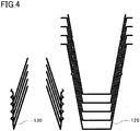
- each of the funnel part 130 and the container body 120 can be stored and transported in a stacked state, before being fixed to each other, thereby reducing costs for storage and distribution.
- the sealing lid 160 is a laminate of films or the like having polyethylene terephthalate and various barrier properties.
- the lower layer film 161 can be made of polyethylene, with an easy peel film or the like as the innermost layer which is the inner surface of the packaging container 100.
- the funnel part 130 is made of a laminated paper in which resin such as polyethylene is laminated on paper, the lower layer film 161 is likely to separate from the funnel part 130 by peeling off the paper layer of the funnel part 130 during refill.
- an easy peel film is preferably used as the innermost layer of the lower layer film 161 regardless of the material of the funnel part 130.
- Lock & Peel (registered trademark) film manufactured by DuPont as the easy peel film allowed favorable opening of the container with an opening strength of 100 N (pushing force required for the lower layer film 160 to be separated from the funnel part 130 and to be torn) by conducting welding with the entire circumferences of the opening portion of the container body 120 at 200°C for 1 second, and welding with the six points of the entire circumferences of the narrow opening end 131 of the plastic funnel part 130, each having a length of 1 mm, at 150°C for 1 second.
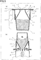
- FIG. 5 is a set of longitudinal sectional views of a packaging container 1 of the present invention, and the longitudinal sectional views illustrate that the contents of the packaging container 1 are refilled into a storage container 6.
- the view shown in (a) of Fig. 5 is a cross sectional view of a container body 2, a funnel part 3, a sealing lid 4 and contents 5 constituting the packaging container 1.
- the container body 2 includes a bottom portion 24, a body portion 25 which serves as a side wall connected to the peripheral edge of the bottom portion, and a flange 22 formed in a horizontal direction from the peripheral edge of the upper end of the body portion.
- the body portion 25 includes a funnel slide portion 23 having a uniform diameter at the upper body portion.
- the funnel slide portion 23 includes an abutment portion 21 at the lower end.
- the abutment portion 21 is configured by a stepped portion, however, it may be configured by a projection.
- the funnel slide portion 23 which is the upper body portion of the container body located at the upper side than the abutment portion 21 is provided such that the funnel part 3 is capable of sliding only along the funnel sliding portion 23, and stopping at any position.
- the funnel part 3 includes a tapered side wall 31 having a frustum shape, a sliding wall 32 provided at the peripheral edge of a large opening diameter of the tapered wall, and a discharge opening 33 provided at the peripheral edge of a small opening diameter of the tapered side wall.
- the tip of the discharge opening 33 can be fused with the sealing lid 4, and it may be entirely fused, or circumferentially fused at some intervals.
- the inside of the tapered side wall 31 is desirably formed such that the contents can easily slide therealong with no resistance in order to be gathered to the center for discharging.
- the sliding wall 32 has a role of allowing the inner wall of the funnel slide portion 23 of the container body 2 to slide therealong, and has a required length for moving parallel without tilting the funnel part 3 during sliding. Further, the sliding wall 32 is configured to have the outer diameter slightly larger than the inner diameter of the funnel slide portion 23, to be stoppable at any position in the funnel slide portion 23.
- the discharge opening 33 provided at the peripheral edge of the small opening diameter of the tapered side wall 31 stores the contents inside the container by being partially fused with the inner surface of the sealing lid 4.
- the fusion strength therebetween is preferably set to be larger than the force required for sliding so as not to break the fusion when sliding the sliding wall 32.
- the sealing lid 4 includes at least two or more layers of a lower layer film 41 and an upper layer film 42.
- the lower layer film 41 has roles of serving as a fusion layer for fusing the peripheral edge of the sealing lid with the flange 22 of the container body 2, and being easily torn when inserting an opening tip 61 of the storage container 6.
- the lower layer film 41 is formed by perforation processing, half cutting or the like as cut lines 43 for the purpose of being easily torn when inserting the opening tip 61 of the storage container 6.
- the upper layer film 42 is configured to be separable by adhering the peripheral edge and at least a part of the center of the upper layer film 42 to the lower layer film 41.
- this configuration allows the upper layer film 42 to be separated from the torn lower layer film 41 to easily deform the sealing lid due to a misalignment between the layers to thereby inserting the opening tip 61 of the storage container 6 to the inside of the opening portion of the container body 2. Further, the upper layer film 42 is simultaneously torn by the force by which the lower layer film 41 is torn along the cut lines 43 to thereby open the container.
- the view show in (b) of Fig. 5 is a longitudinal cross sectional view of the packaging container 1, and the longitudinal sectional view illustrates that the packaging container 1 is pushed into the opening tip 61 of the storage container 6 for refilling.
- the packaging container 1 is inverted for pushing the center of the sealing lid 4 into the opening tip 61 of the storage container 6, the lower end of the sliding wall 32 of the funnel part 3 collides with and is stopped at the abutment portion 21. Accordingly, since there is no other escape space for the sealing lid 4, the laminated upper layer film 42 of the sealing lid 4 is torn with the lower layer film 41 along the cut lines 43 by the pushing force.
- the discharge opening 33 of the funnel part 3 of the packaging container 1 is inserted into the opening tip 61 of the storage container 6.
- the opening tip 61 of the storage container 6 is inserted between the flange 22 of the packaging container 1 and the discharge opening 33 of the funnel part 3.
- the torn film of the sealing lid 4 is widely cut at the center thereof to be opened, and the cut sealing lid 4 is deformed along the opening tip 61 of the storage container 6 while the lower layer film 41 is separated from the upper layer film 42 to thereby open the center of the sealing lid 4.
- the contents 5 are reliably filled into to the storage container 6 without being spilled to the outside thereof.
- the role of the upper layer film 42 is to protect the contents by imparting barrier properties, and to protect the lower layer film 41 having the cut lines.
- Fig. 6 is a set of longitudinal sectional views of the packaging container 1, and the longitudinal sectional views illustrate that the external air pressure of the packaging container has changed relative to the internal pressure of the packaging container.
- the view shown in (a) of Fig. 6 is a cross sectional view of the container 1 in a normal state, and the cross sectional view illustrates that the internal air pressure of the packaging container 1 is the same as the external air pressure thereof, and the sealing lid 4 is an approximately flat surface.
- the view shown in (b) of Fig. 6 illustrates that the sealing lid 4 is pushed from the exterior of the packaging container 1 in the state that the external air pressure of the packaging container 1 is larger than the internal air pressure thereof.
- FIG. 6 illustrates that the packaging container 1 is under a low external air pressure, that is, such as on high mountains such as Mt. Fuji. or Mt Everest, or inside an aircraft. Under such a low air pressure, since the internal air pressure becomes relatively high, the packaging container 1 is bulged, thereby pushing the sealing lid 4 to the outside.
- the funnel part 3 is not fixed to the container body 2 while the discharge opening 33 of the funnel part 3 is fused with the center of the sealing lid 4. Accordingly, the entire funnel part 3 is allowed to smoothly slide toward the outside. Therefore, the fused portion between the center of the sealing lid 4 and the discharge opening 33 of the funnel part 3 is prevented from being separated.
- the view shown in (d) of Fig. 6 illustrates that the packaging container 1 is turned upside down for refilling. Since the fused portion between the center of the sealing lid 4 and the discharge opening 33 of the funnel part 3 is not to be separated, the contents 5 are not spilled to the outside of the funnel part 3 even when in an upside-down state.
- the funnel part 3 moves downward, but this does not cause any problem because the funnel part 3 is pushed into the abutment portion 21 when the sealing lid 4 is pushed into the opening tip 61 of the storage container 6 during refilling.
- the view shown in (a) of Fig. 11 is a cross sectional view of a packaging container in which the funnel part 3 is fixed to the container body, and the sealing lid 4 is not fused with the discharge opening 33 for comparison with the present invention.
- a packaging container since the sealing lid of the container is bulged outward due to the difference in air pressure between inside and outside the container when the packaging container is brought into places with low air pressure such as a high area or an aircraft in flight, the contents enter the gap between the outside of the funnel part and the sealing lid. Accordingly, the contents entering the gap are spilled outside the storage container during refilling, resulting in the problem that the contents cannot be fully refilled.
- the sealing lid at the periphery of the funnel part is only pushed inward when the external air pressure is high, whereas the sealing lid at the periphery of the funnel part is bulged outward when the external air pressure becomes low. Then, as shown in (c) of Fig. 11 , the sealing lid 4 is further bulged, and the sealing lid is separated from a fused portion 44 in which it is fused with the funnel part. The separation of the sealing lid from the fused portion 44 results in the problem that the contents 5 are spilled to the outside of the funnel part through a gap generated by the separation when the container vibrates during transport, or the container is turned upside down for refilling, as shown in (d) of Fig. 11 . Hence, refilling the contents to the container to be refilled includes problems such that the sealing lid is not evenly torn, or a large amount of contents 5 are spilled outside the packaging container.
- Fig. 7 is a set of plan view of the exemplary sealing lid 4 according to the present embodiment, and longitudinal sectional views which schematically illustrate how the cross section of the sealing lid is to be torn.
- the view shown in (a) of Fig. 7 is a plan view of the sealing lid 4 provided with the cut lines 43 which radiate from the center.
- the cut lines 43 are formed by applying processing such as perforation, and formed on the lower layer film 41 while not being formed on the upper layer film 42.
- the views shown in (c), (d) and (e) of Fig. 7 illustrate that the sealing lid 4 is torn when it is pushed from the upper layer film 42 during refilling.
- the upper layer film 42 is also torn by following the cut lines 43 on the lower layer film 41. As the upper layer film 42 is torn, it is separated from the lower layer film 41, and more likely to be deformed.
- Fig. 8 is a set of a plan view of another exemplary sealing lid 4 according to the present embodiment, and longitudinal sectional views which schematically illustrate how the cross section of the sealing lid 4 is to be torn.
- the view shown in (a) of Fig. 8 is a plan view of the sealing lid 4 provided with the cut lines 431 which radiate from the center. These cut lines 431 are formed by applying processing such as perforation, however, the processing is only applied for the center which does not include an adhesive region 45 between the upper layer film 42 and the lower layer film 41.
- the adhesive region 45 is not necessarily in a doughnut shape as shown in (a) of Fig. 8 , unless the cut lines 43 are not included.
- weakened lines 431 are formed on the lower layer film 41 such that the lower layer film 41 is partially torn through the thickness thereof, while not being formed on the upper layer film 42.
- the upper layer film 42 has a surface laminated with an easy peel film on a side to be adhered to the lower layer film 41, the easy peel film having low adhesiveness being laminated so as not to affect the weakened lines 431 of the lower layer film 41. Accordingly, the upper layer film 42 can be separated from the lower layer film 41. As shown in (c) of Fig. 8 , the upper layer film 42 is separated.
- the views shown in (d) and (e) of Fig. 8 illustrate that the sealing lid 4 is pressed to be torn during subsequent refilling.
- the weakened lines 431 are broken as shown in Fig. 5-4 , and then the sealing lid 4 is torn when it is completely pushed into the opening tip 61 of the storage container from the upper side as shown in (e) of Fig. 8 .
- the torn portion of the lower layer film 41 is increased.
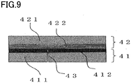
- Fig. 9 is a schematic cross sectional view of an exemplary laminated sheet which constitutes the sealing lid 4.
- a laminated film including a barrier film 421 and an easy peel film 422 is used as the upper layer film 42
- a laminated film including a polyethylene terephthalate film 412 and a polyethylene film which is a sealant layer 411 is used as the lower layer film 41.
- the lower layer film 41 includes a perforation thereon as the cut lines 43.
- the upper layer film 42 includes the easy peel film 422 on the inner side.
- the upper layer film 42 is separated from the lower layer film 41 when they become misaligned at the boundary therebetween, followed by conforming to the shape of the opening tip of the container to be refilled which is pushed into the lower layer film 41. Therefore, the contents are prevented from being spilled in the vicinity of the opening tip.
- These laminated sheets are manufactured by manufacturing a laminated film using a dry laminating machine, an extruder laminating machine or the like, followed by punching the laminated film using a punching die.
- the sealing lid 4 may be provided with an over cap thereon cap thereon to protect against dirt and tearing during transport.
- the laminated film of the barrier film 421 and the easy peel film 422 having low adhesiveness are used as the upper layer film 42.
- the laminated film of the polyethylene terephthalate film 412 and the polyethylene film which serves as the sealant layer 411 are used as the lower layer film 41.
- the lower layer film 41 includes a perforation thereon as the cut lines 43.
- the upper layer film 42 includes the easy peel film 422 having low tackiness, thereby allowing easy separation from the lower layer film 41.
- the cut lines 43 of the lower layer film 41 can be prevented from being dragged and broken when the upper layer film 42 is separated from the lower layer film 41, or the lower layer film 41 can be prevented from being torn due to vibration during transport.
- the container is covered only with the lower layer film 41. Accordingly, when a container mouth is pushed onto the cut lines 43, the lower layer film 41 is easily torn so as to open the container.
- the upper layer film 42 can be formed so as to be durable while having high barrier properties, storage performance can be improved while minimizing degradation of the contents.
- This lid material can also be manufactured by manufacturing a laminated film using a dry laminating machine, an extruder laminating machine or the like, and then partially heat-sealing the laminated film, followed by punching the laminated film using a punching die.
- the patterns of non-adhesive regions on the upper layer film and the lower layer film are laminated after being printed and processed on the films in advance, however, they may be laminated by printing the pattern of the adhesive region with adhesive agents.
- resin dispersion film in a micellar state is preferably used, in which olefin resin is kneaded with resin having low fusing properties relative to the material of the lower layer film such as styrene resin, acrylic acid ester, vinyl acetate resin, phthalic anhydride modified polyolefin or other olefin resin.
- resin having low fusing properties relative to the material of the lower layer film
- resin having low fusing properties relative to the material of the lower layer film such as styrene resin, acrylic acid ester, vinyl acetate resin, phthalic anhydride modified polyolefin or other olefin resin.
- polyester-based materials may be used.
- the film having a low adhesiveness can be easily adjusted by reducing the ratio of olefin resin, or the like.
- the sealant layer 411 may be formed of linear low density polyethylene, high pressure low density polyethylene, or a material to which ethylene and vinyl acetate copolymer, low polymerization resin or the like is added for ease of fusion at low temperature. Further, the polyethylene terephthalate film 412 is biaxially stretched, however, it may be a biaxially stretched polypropylene film or the like.
- the container body 2 used for the packaging container 1 of the present embodiment can be manufactured using injection molding, blow molding, vacuum/pressure molding or the like.
- the material can include a variety of molding resins such as an olefin resin such as polypropylene, polyethylene, polymethylpentene or cyclic polyolefin resin, a styrene resin such as styrene-acrylonitrile copolymer resin, acrylonitrile-butadiene-styrene copolymer resin or polystyrene resin, an acrylonitrile resin or a polyphenylene resin.
- an olefin resin such as polypropylene, polyethylene, polymethylpentene or cyclic polyolefin resin
- a styrene resin such as styrene-acrylonitrile copolymer resin, acrylonitrile-butadiene-styrene copolymer resin or polystyrene resin, an acrylonitrile
- the abutment portion 21 may be formed by an inner slide structure (collapsible core) with a rib provided on the inner surface of the container body 2, or may be partially butted so as to be an inclined pin except for being formed in the stepped portion. Further, the container body 2 may be formed not by a plastic, but pulp molding, In this case, hot melted adhesive agents or the like are preferably used instead of the sealant layer of the sealing lid 4.
- the funnel part 3 used for the packaging container 1 of the present embodiment may be manufactured using injection molding, blow molding, vacuum/pressure molding or the like.
- the material can include a variety of molding resins such as an olefin resin such as polypropylene, polyethylene, polymethylpentene or cyclic polyolefin resin, styrene resin such as styrene-acrylonitrile copolymer resin, acrylonitrile-butadiene-styrene copolymer resin or polystyrene resin, acrylonitrile resin or polyphenylene resin.
- an olefin resin such as polypropylene, polyethylene, polymethylpentene or cyclic polyolefin resin
- styrene resin such as styrene-acrylonitrile copolymer resin, acrylonitrile-butadiene-styrene copolymer resin or polystyrene resin, acrylonitrile resin or polyphenylene resin.
- the material in which resin such as polyethylene is laminated onto the both surfaces of the paper of the substrate may be used for shaping by conducting punching, folding and laminating.
- the outer surface of the sliding wall 32 is preferably made of a material different from that of the container body 2 to impart slidability.
- the packaging container 1 of the present embodiment is a secure container capable of reliable refilling without problems such that the contents are spilled outside a storage container during refilling, even if it is used as a packaging container when refilling at a place of a high altitude such as a mountain lodge or a ski site, exporting overseas or air transporting to isolated islands.
- the packaging container 1 since the packaging container 1 has a high productivity, and is stably produced, non-defective product ratio is improved, and the cost is reduced. Accordingly, the present invention has large advantageous effects.
- the funnel part when the funnel part is attached to the container body, it does not move to the position at least closer to the bottom portion than to the predetermined position, thereby facilitating positioning. Accordingly, the manufacturing cost can be reduced. Furthermore, in the packaging container according to the second embodiment, the funnel part is more likely to follow the bulge of the sealing lid due to sliding of the sliding wall even under a low external air pressure. Accordingly, the contents are less likely to enter the gap of the fused portion between the sealing lid and the funnel. Therefore, the whole amount of the contents can be smoothly refilled into the storage container without being spilled outside the storage container during refilling.
- the present invention can be implemented by appropriately interchanging the components of the above embodiments, or appropriately changing and omitting the features of the components.
- the aspect of the engagement mechanism is not limited, and it can be variously implemented if the movement of the funnel part can be restricted by the interference between the wide opening end of the funnel part and the engagement mechanism provided at the predetermined position of the container body.
- the present invention is useful for packaging containers or the like for transferring of the fluid substances such as powdered, granular or liquid substances into other containers.
Landscapes
- Engineering & Computer Science (AREA)
- Mechanical Engineering (AREA)
- Packages (AREA)
- Closures For Containers (AREA)
Abstract
Description
- The present invention relates to a packaging container that facilitates transfer of fluid contents such as powdered, granular or liquid contents into other containers.
- Packaging containers disclosed in
PTLs 1 to 4 are known as packaging containers which facilitate refill of powdered or granular contents such as instant coffee into a storage container or a tank of a coffee machine.Fig. 10 shows a longitudinal sectional view of apackaging container 900 according to an example of such a packaging container. Thepackaging container 900 includes acylindrical container body 920, afunnel part 930 fixed to an inner wall of thecontainer body 920, and asealing lid 960. The inside of thecontainer body 920 is filled withcontents 950 such as powders, and the opening portion of thecontainer body 920 is sealed by the sealinglid 960. Thesealing lid 960 has alower layer film 961 and anupper layer film 962 which are removably laminated, and thelower layer film 961 includes cut lines which radially extend from the center of thelower layer film 961. The sealinglid 960 is sealed to the opening portion of thecontainer body 920 in the state that it is in contact with a narrowopening end 931 of the funnel part. - When the
contents 950 of thepackaging container 900 are refilled into other containers, atab 905 is pulled up to separate theupper layer film 962 from thelower layer film 961, and then thelower layer film 961 is pushed while being applied to the opening portion of a container to be refilled to break thelower layer film 961 along the cut lines. Accordingly, thecontents 950 can be easily refilled into the container through thefunnel part 930. -
- PTL 1:
JP-2009-280284 A - PTL 2:
JP-2013-220823 A - PTL 3:
JP-2014-1014 A - PTL 4:
JP-5365789 B - When manufacturing such a
packaging container 900, thefunnel part 930 is fixed to thecontainer body 920 by, for example, inserting thefunnel part 930 into thecontainer body 920 for positioning, followed by high-frequency melting and bonding a portion where the inner wall of thecontainer body 920 is in contact with thefunnel part 930. Alternatively, thefunnel part 930 is adhered and fixed to thecontainer body 920 by being inserted into thecontainer body 920 in the state that a portion of the inner wall of thecontainer body 920 to which thefunnel part 930 is to be fixed is heated and melted in advance. - However, since the
container body 920 is in a straight shape having a uniform diameter, thefunnel part 930 can be inserted into a position lower than a position to which thefunnel part 930 is to be fixed. Hence, it is difficult to accurately insert thefunnel part 930 to the position to which thefunnel part 930 is to be fixed, and maintain the position until thefunnel part 930 is fixed to thecontainer body 920. Such a positioning with high accuracy requires a complex and expensive device and apparatus, thus resulting in high manufacturing cost. - An object of the present invention is to facilitate positioning of a portion to which a funnel-shaped spout is to be attached and reduce manufacturing costs for a packaging container in which the funnel-shaped spout is attached to the container body.
- An aspect of the present invention is a packaging container including: a container body having a body portion provided with an engaging wall, and a bottom portion provided at the first end of the body portion; a funnel part having a funnel shape inserted into the body portion, and a wide opening end thereof is restricted from being moved toward at least the first end; and a sealing lid sealed to an opening portion which serves as a second end of the body portion while being in contact with a narrow opening end of the funnel part to seal the container body.
- According to the present invention, in a packaging container in which a funnel-shaped spout is attached to the container body, positioning of a portion to which the funnel-shaped spout is to be attached is facilitated, and manufacturing costs are reduced.
-
-
Fig. 1 is a perspective view of a packaging container according to a first embodiment of the present invention. -
Fig. 2 is a longitudinal sectional view of the packaging container according to the first embodiment of the present invention. -
Fig. 3 is a set of longitudinal sectional views of a funnel part according to the first embodiment of the present invention. -
Fig. 4 is a longitudinal sectional view of the funnel part and a container body according to the first embodiment of the present invention, and the longitudinal sectional view illustrates that they are in a stored state. -
Fig. 5 is a set of longitudinal sectional views of a packaging container according to a second embodiment of the present invention, and the longitudinal sectional views illustrate that the contents of the packaging container are being refilled into a storage container. -
Fig. 6 is a set of longitudinal sectional views of the packaging container according to the second embodiment of the present invention, and the longitudinal sectional views illustrate that the outer air pressure of the packaging container changes relative to the inner pressure of the packaging container. -
Fig. 7 is a set of a plan view of an exemplary sealing lid used for the packaging container according to the second embodiment of the present invention, and longitudinal sectional views which schematically illustrate how the cross section of the sealing lid is to be torn. -
Fig. 8 is a set of a plan view of another exemplary sealing lid used for the packaging container according to the second embodiment of the present invention, and longitudinal sectional views which schematically illustrate how the cross section of the sealing lid is to be torn. -
Fig. 9 is a schematic cross sectional view of an exemplary laminated sheet constituting the sealing lid according to the second embodiment of the present invention. -
Fig. 10 is a longitudinal sectional view of a conventional packaging container. -
Fig. 11 is a set of a longitudinal sectional view of the conventional packaging container, the longitudinal sectional views illustrating that the external air pressure of the packaging container has changed relative to the internal pressure of the packaging container. - Hereinafter, a first embodiment of the present invention will be described.
Fig. 1 is a perspective view of apackaging container 100, andFig. 2 is a longitudinal sectional view of thepackaging container 100 taken along the line A-A' ofFig. 1 . Thepackaging container 100 includes acylindrical container body 120 having a bottom portion and an opening portion, afunnel part 130 and asealing lid 160. Inside thecontainer body 120 is filled withcontents 150 such as powders, and the opening portion of thecontainer body 120 is sealed by a sealinglid 160. - The
container body 120 includes abottom portion 121 and abody portion 122. Thebottom portion 121 is attached to the first end of thebody portion 122. Thebody portion 122 is in a tapered shape in which the diameter is gradually increased from thebottom portion 121 toward the second end which serves as an opening portion of thecontainer body 120. On thebody portion 122, anengaging groove 123 is projected outward, which structures a recessed portion in thebody portion 122 is formed at a predetermined portion such that it surrounds thebody portion 122. - The
funnel part 130 is in a funnel shape having a narrow opening end and a wide opening end. Thefunnel part 130 has a wideopening end 132 in which anengaging portion 134 having aprojection 133 projected outward is formed. Theprojection 133 is fitted into theengaging groove 123. - The
sealing lid 160 includes alower layer film 161 which is sealed to the opening portion of thecontainer body 120, and anupper layer film 162 laminated on the outer surface of thelower layer film 161 such that it can be separated therefrom. Thelower layer film 161 is provided withradial cut lines 199 such as a perforation, and are torn by being pushed by a container to be refilled when in use. Theupper layer film 162 is provided to protect thecut lines 199 formed on thelower layer film 161, and to ensure the sealing ability of thepackaging container 100, and is separated from thelower layer film 161 when in use. Theupper layer film 162 is provided with atab 105 at a portion of the outer peripheral edge so as to be easily held when being separated from thelower layer film 161. - The
lower layer film 161 of thesealing lid 160 is welded with the narrowopening end 131 of thefennel part 130. They are preferably welded at a low adhesion strength such that it does not obstruct opening thepackaging container 100 but does not allow the welding to break before opening thepackaging container 100. The low adhesion strength is preferably lower than, for example, that of a portion where thelower layer film 161 of thesealing lid 160 is sealed with the opening portion of thecontainer body 120. This welding can prevent thecontents 150 from being moved from the inside to the outside of thefunnel part 130 through the gap between the narrowopening end 131 and thelower layer film 160. Accordingly thecontents 150 are prevented from being spilled out of the container to be refilled without entering the container during refilling, which will be described later. The narrowopening end 131 of thefunnel part 130 may be in the same plane as the opening portion of thecontainer body 120, or may be offset outward from thecontainer body 120 and also from a plane which includes the opening portion to increase a contact pressure with thesealing lid 160. - When the
contents 150 of thepackaging container 100 are refilled, theupper layer film 162 is separated, and then thelower layer film 161 is pushed while being applied to the opening portion of a container to be refilled to thereby tear thelower layer film 161 along thecut lines 199 while breaking the welding between thelower layer film 161 and the narrowopening end 131 of thefunnel part 130. Accordingly, thepackaging container 100 is opened, and thecontents 150 are funneled into the container to be refilled through thefunnel part 130. - The materials of the
container body 120 and thefunnel part 130 are not limited. However, when using a laminated paper or plastic or the like, thefunnel part 130 can be more firmly fixed to thebody portion 122 by at least partially welding theengaging portion 134 with theengaging groove 123. Theprojection 133 of theengaging portion 134 may be fixed to theengaging groove 123 by inserting thefunnel part 130 into thebody portion 122 from the wide opening side in the state that theengaging portion 134 and theengaging groove 123 are heated in advance to be partially melted, and then engaging and adhering theprojection 133 of theengaging portion 134 to theengaging groove 123. Alternatively, theprojection 133 of the engagingportion 134 may be fixed to the engaginggroove 123 by heating and the welding the engagement portion in the state that theprojection 133 of the engagingportion 134 is engaged to the engaginggroove 123. The method of heating is not limited. However, when thebody portion 122 includes an aluminum foil as a barrier layer, for example, high frequency heating can be conducted after engagement. Further, theprojection 133 of the engagingportion 134 may be fixed to the engaginggroove 123 by not necessarily heating, or by using adhesive agents. Alternatively, theprojection 133 of the engagingportion 134 may be fixed to the engaginggroove 123 only by engagement of the engagingportion 134 and the engaginggroove 123 without welding, adhering or the like. - According to the present embodiment, the engaging
portion 134 is configured to be extended in a form of being outwardly folded back from thewide opening end 132 of thefunnel part 130, and has a bending portion forming theprojection 133 at the end thereof. The engagingportion 134 has a tapered portion forming the same tapered angle as that of thebody portion 122 except for theprojection 133, and is in surface contact with thebody portion 122. The engagement between theprojection 133 and the engaginggroove 123, and the surface contact of the tapered portions, restricts the movement of thefunnel part 130 toward the portion closer to thebottom portion 121 than to the portion to which thefunnel part 130 is to be fixed, and thus facilitates positioning when thefunnel part 130 is inserted into thebody portion 122. Since the diameter of the opening portion of thebody portion 122 is larger than the maximum diameter of thefunnel part 130, thefunnel part 130 is easily inserted to the fixing position. Therefore, high accuracy is not required for positioning or the like, thereby reducing costs for the machines required for manufacturing. Although thefunnel part 130 is pushed toward thebottom portion 121 of thecontainer body 120, the position thereof is hardly shifted during storing thepackaging container 100, or refilling the contents. Accordingly, stable storage or refill can be achieved. - Contrary to the present embodiment, if the engaging groove is formed so as to be inwardly projected on the
body portion 122, the projected portion of the groove might be crushed, which might cause impairing of the function of engaging when thefunnel part 130 comes into contact with the engaging groove. Further, the engaging groove can be formed by, for example, pushing the rotating body against thebody portion 122 so that the rotating body surrounds thebody portion 122. However, the engaging groove can be more easily formed by attaching a female mold to the outer surface of thebody portion 122, and pushing the rotating body from the inner surface of thebody portion 122 to make the engaging groove outwardly projected on thebody portion 122, rather than by attaching a male mold to the inner surface of thebody portion 122, and pushing the rotating body from the outer surface of thebody portion 122 to make the engaging groove inwardly projected on thebody portion 122. Accordingly, as described above, it is preferred that the engaginggroove 123 is formed so as to be projected outward on thebody portion 122. -
Fig. 3 shows modified examples of the shape of thefunnel part 130.Fig. 3 shows a set of one of the two cross sections of the funnel parts according to modified examples, and each of the cross sections is symmetric with the surface passing through a center axis indicated by the dot-and-dash line. In the example shown in (a) ofFig. 3 , theprojection 133 is formed in a shape in which it is outwardly bent at thewide opening end 132 of thefunnel part 130, thereby constituting the entire engagingportion 134. In the example shown in (b) ofFig. 3 , theprojection 133 is formed in a shape in which it is outwardly curled at thewide opening end 132 of thefunnel part 130, thereby constituting the entire engagingportion 134. In the example shown in (c) ofFig. 3 , similar to the example shown in (b), theprojection 133 is formed in a shape in which it is outwardly curled at thewide opening end 132 of thefunnel part 130, however, the taper of thefunnel part 130 varies, thereby being in surface contact with thebody portion 122 in the vicinity of theprojection 133. The engagingportion 134 is constituted by this portion in surface contact with thebody portion 122 and theprojection 133. - For the
funnel part 130 shown inFig. 2 and (a) ofFig. 3 , a plastic is preferably used in order to secure the strength of the portion where thewide opening end 132 is folded back. For thefunnel part 130 shown in (b) and (c) ofFig. 3 , a paper or a laminated paper is preferably used in order to facilitate forming the curled shape of theprojection 133. These funnel parts maybe appropriately modified considering, for example, how thelower layer film 161 is likely to be torn, or how the contents are likely to be funneled, when refiling the contents, described above. For instance, a certain portion including the narrow opening end of the funnel part may be in the straight shape having uniform diameter. The example of thefunnel part 130 shown inFig. 2 in which a portion closer to the narrow opening is in a straight shape is shown in (d) ofFig. 3 . - As shown in a cross sectional view of
Fig. 4 , each of thefunnel part 130 and thecontainer body 120 can be stored and transported in a stacked state, before being fixed to each other, thereby reducing costs for storage and distribution. - The sealing
lid 160 is a laminate of films or the like having polyethylene terephthalate and various barrier properties. Thelower layer film 161 can be made of polyethylene, with an easy peel film or the like as the innermost layer which is the inner surface of thepackaging container 100. When thefunnel part 130 is made of a laminated paper in which resin such as polyethylene is laminated on paper, thelower layer film 161 is likely to separate from thefunnel part 130 by peeling off the paper layer of thefunnel part 130 during refill. - On the other hand, when various easy peel films are used as the innermost layer of the
lower layer film 161, it was confirmed that the adhesion strength between thelower layer film 161 and thefunnel part 130 becomes lower than that between thelower layer film 161 and the opening portion of thecontainer body 120 by controlling the welding temperature, welding area or the like even if thefunnel part 130 is any of a simple paper, a laminated paper, or a plastic. Accordingly, an easy peel film is preferably used as the innermost layer of thelower layer film 161 regardless of the material of thefunnel part 130. - For example, the use of Lock & Peel (registered trademark) film manufactured by DuPont as the easy peel film allowed favorable opening of the container with an opening strength of 100 N (pushing force required for the
lower layer film 160 to be separated from thefunnel part 130 and to be torn) by conducting welding with the entire circumferences of the opening portion of thecontainer body 120 at 200°C for 1 second, and welding with the six points of the entire circumferences of thenarrow opening end 131 of theplastic funnel part 130, each having a length of 1 mm, at 150°C for 1 second. - Hereinafter, a second embodiment of the present invention will be described.
Fig. 5 is a set of longitudinal sectional views of apackaging container 1 of the present invention, and the longitudinal sectional views illustrate that the contents of thepackaging container 1 are refilled into astorage container 6. The view shown in (a) ofFig. 5 is a cross sectional view of acontainer body 2, afunnel part 3, a sealinglid 4 andcontents 5 constituting thepackaging container 1. Thecontainer body 2 includes abottom portion 24, a body portion 25 which serves as a side wall connected to the peripheral edge of the bottom portion, and aflange 22 formed in a horizontal direction from the peripheral edge of the upper end of the body portion. Furthermore, the body portion 25 includes afunnel slide portion 23 having a uniform diameter at the upper body portion. Thefunnel slide portion 23 includes anabutment portion 21 at the lower end. In the example shown in (a) ofFig. 5 , theabutment portion 21 is configured by a stepped portion, however, it may be configured by a projection. Thefunnel slide portion 23 which is the upper body portion of the container body located at the upper side than theabutment portion 21 is provided such that thefunnel part 3 is capable of sliding only along thefunnel sliding portion 23, and stopping at any position. - The
funnel part 3 includes a taperedside wall 31 having a frustum shape, a slidingwall 32 provided at the peripheral edge of a large opening diameter of the tapered wall, and adischarge opening 33 provided at the peripheral edge of a small opening diameter of the tapered side wall. The tip of thedischarge opening 33 can be fused with the sealinglid 4, and it may be entirely fused, or circumferentially fused at some intervals. The inside of the taperedside wall 31 is desirably formed such that the contents can easily slide therealong with no resistance in order to be gathered to the center for discharging. The slidingwall 32 has a role of allowing the inner wall of thefunnel slide portion 23 of thecontainer body 2 to slide therealong, and has a required length for moving parallel without tilting thefunnel part 3 during sliding. Further, the slidingwall 32 is configured to have the outer diameter slightly larger than the inner diameter of thefunnel slide portion 23, to be stoppable at any position in thefunnel slide portion 23. Thedischarge opening 33 provided at the peripheral edge of the small opening diameter of the taperedside wall 31 stores the contents inside the container by being partially fused with the inner surface of the sealinglid 4. The fusion strength therebetween is preferably set to be larger than the force required for sliding so as not to break the fusion when sliding the slidingwall 32. - The sealing
lid 4 includes at least two or more layers of a lower layer film 41 and anupper layer film 42. The lower layer film 41 has roles of serving as a fusion layer for fusing the peripheral edge of the sealing lid with theflange 22 of thecontainer body 2, and being easily torn when inserting anopening tip 61 of thestorage container 6. The lower layer film 41 is formed by perforation processing, half cutting or the like as cut lines 43 for the purpose of being easily torn when inserting theopening tip 61 of thestorage container 6. Theupper layer film 42 is configured to be separable by adhering the peripheral edge and at least a part of the center of theupper layer film 42 to the lower layer film 41. When inserting theopening tip 61 of thestorage container 6, this configuration allows theupper layer film 42 to be separated from the torn lower layer film 41 to easily deform the sealing lid due to a misalignment between the layers to thereby inserting theopening tip 61 of thestorage container 6 to the inside of the opening portion of thecontainer body 2. Further, theupper layer film 42 is simultaneously torn by the force by which the lower layer film 41 is torn along the cut lines 43 to thereby open the container. - The view show in (b) of
Fig. 5 is a longitudinal cross sectional view of thepackaging container 1, and the longitudinal sectional view illustrates that thepackaging container 1 is pushed into theopening tip 61 of thestorage container 6 for refilling. When thepackaging container 1 is inverted for pushing the center of the sealinglid 4 into theopening tip 61 of thestorage container 6, the lower end of the slidingwall 32 of thefunnel part 3 collides with and is stopped at theabutment portion 21. Accordingly, since there is no other escape space for the sealinglid 4, the laminatedupper layer film 42 of the sealinglid 4 is torn with the lower layer film 41 along the cut lines 43 by the pushing force. Immediately after tearing of the cut lines 43 of the sealinglid 4, the discharge opening 33 of thefunnel part 3 of thepackaging container 1 is inserted into theopening tip 61 of thestorage container 6. At the same time, theopening tip 61 of thestorage container 6 is inserted between theflange 22 of thepackaging container 1 and the discharge opening 33 of thefunnel part 3. Furthermore, the torn film of the sealinglid 4 is widely cut at the center thereof to be opened, and thecut sealing lid 4 is deformed along theopening tip 61 of thestorage container 6 while the lower layer film 41 is separated from theupper layer film 42 to thereby open the center of the sealinglid 4. Hence, thecontents 5 are reliably filled into to thestorage container 6 without being spilled to the outside thereof. - When the
upper layer film 42 can be easily separated from the lower layer film 41, and the lower layer film 41 is not provided with the cut lines at the entire surface thereof, refilling may be conducted after separating theupper layer film 42. In this case, the role of theupper layer film 42 is to protect the contents by imparting barrier properties, and to protect the lower layer film 41 having the cut lines. -
Fig. 6 is a set of longitudinal sectional views of thepackaging container 1, and the longitudinal sectional views illustrate that the external air pressure of the packaging container has changed relative to the internal pressure of the packaging container. The view shown in (a) ofFig. 6 is a cross sectional view of thecontainer 1 in a normal state, and the cross sectional view illustrates that the internal air pressure of thepackaging container 1 is the same as the external air pressure thereof, and the sealinglid 4 is an approximately flat surface. The view shown in (b) ofFig. 6 illustrates that the sealinglid 4 is pushed from the exterior of thepackaging container 1 in the state that the external air pressure of thepackaging container 1 is larger than the internal air pressure thereof. However, since the lower end of thefunnel slide portion 23 collides with and stops at theabutment portion 21, the portions of the sealinglid 4 in which the flanges and the tip of the discharge opening 33 of thefunnel part 3 are located are only slightly deformed without considerable deformation. The view shown in (c) ofFig. 6 illustrates that thepackaging container 1 is under a low external air pressure, that is, such as on high mountains such as Mt. Fuji. or Mt Everest, or inside an aircraft. Under such a low air pressure, since the internal air pressure becomes relatively high, thepackaging container 1 is bulged, thereby pushing the sealinglid 4 to the outside. In thepackaging container 1 of the present invention, however, thefunnel part 3 is not fixed to thecontainer body 2 while the discharge opening 33 of thefunnel part 3 is fused with the center of the sealinglid 4. Accordingly, theentire funnel part 3 is allowed to smoothly slide toward the outside. Therefore, the fused portion between the center of the sealinglid 4 and the discharge opening 33 of thefunnel part 3 is prevented from being separated. The view shown in (d) ofFig. 6 illustrates that thepackaging container 1 is turned upside down for refilling. Since the fused portion between the center of the sealinglid 4 and the discharge opening 33 of thefunnel part 3 is not to be separated, thecontents 5 are not spilled to the outside of thefunnel part 3 even when in an upside-down state. When thepackaging container 1 is turned upside down, thefunnel part 3 moves downward, but this does not cause any problem because thefunnel part 3 is pushed into theabutment portion 21 when the sealinglid 4 is pushed into theopening tip 61 of thestorage container 6 during refilling. - The view shown in (a) of
Fig. 11 is a cross sectional view of a packaging container in which thefunnel part 3 is fixed to the container body, and the sealinglid 4 is not fused with thedischarge opening 33 for comparison with the present invention. In such a packaging container, since the sealing lid of the container is bulged outward due to the difference in air pressure between inside and outside the container when the packaging container is brought into places with low air pressure such as a high area or an aircraft in flight, the contents enter the gap between the outside of the funnel part and the sealing lid. Accordingly, the contents entering the gap are spilled outside the storage container during refilling, resulting in the problem that the contents cannot be fully refilled. As shown in (b) ofFig. 11 , the sealing lid at the periphery of the funnel part is only pushed inward when the external air pressure is high, whereas the sealing lid at the periphery of the funnel part is bulged outward when the external air pressure becomes low. Then, as shown in (c) ofFig. 11 , the sealinglid 4 is further bulged, and the sealing lid is separated from a fused portion 44 in which it is fused with the funnel part. The separation of the sealing lid from the fused portion 44 results in the problem that thecontents 5 are spilled to the outside of the funnel part through a gap generated by the separation when the container vibrates during transport, or the container is turned upside down for refilling, as shown in (d) ofFig. 11 . Hence, refilling the contents to the container to be refilled includes problems such that the sealing lid is not evenly torn, or a large amount ofcontents 5 are spilled outside the packaging container. -
Fig. 7 is a set of plan view of theexemplary sealing lid 4 according to the present embodiment, and longitudinal sectional views which schematically illustrate how the cross section of the sealing lid is to be torn. The view shown in (a) ofFig. 7 is a plan view of the sealinglid 4 provided with the cut lines 43 which radiate from the center. As shown in (b) ofFig. 7 illustrating the cross section, the cut lines 43 are formed by applying processing such as perforation, and formed on the lower layer film 41 while not being formed on theupper layer film 42. The views shown in (c), (d) and (e) ofFig. 7 illustrate that the sealinglid 4 is torn when it is pushed from theupper layer film 42 during refilling. Theupper layer film 42 is also torn by following the cut lines 43 on the lower layer film 41. As theupper layer film 42 is torn, it is separated from the lower layer film 41, and more likely to be deformed. -
Fig. 8 is a set of a plan view of anotherexemplary sealing lid 4 according to the present embodiment, and longitudinal sectional views which schematically illustrate how the cross section of the sealinglid 4 is to be torn. The view shown in (a) ofFig. 8 is a plan view of the sealinglid 4 provided with the cut lines 431 which radiate from the center. These cut lines 431 are formed by applying processing such as perforation, however, the processing is only applied for the center which does not include an adhesive region 45 between theupper layer film 42 and the lower layer film 41. The adhesive region 45 is not necessarily in a doughnut shape as shown in (a) ofFig. 8 , unless the cut lines 43 are not included. As shown in (b) ofFig. 8 illustrating the cross section, weakened lines 431 are formed on the lower layer film 41 such that the lower layer film 41 is partially torn through the thickness thereof, while not being formed on theupper layer film 42. Theupper layer film 42 has a surface laminated with an easy peel film on a side to be adhered to the lower layer film 41, the easy peel film having low adhesiveness being laminated so as not to affect the weakened lines 431 of the lower layer film 41. Accordingly, theupper layer film 42 can be separated from the lower layer film 41. As shown in (c) ofFig. 8 , theupper layer film 42 is separated. The views shown in (d) and (e) ofFig. 8 illustrate that the sealinglid 4 is pressed to be torn during subsequent refilling. That is, the weakened lines 431 are broken as shown inFig. 5-4 , and then the sealinglid 4 is torn when it is completely pushed into theopening tip 61 of the storage container from the upper side as shown in (e) ofFig. 8 . As the lower layer film 41 is torn throughout the entire thickness thereof by following the cut lines 43 of the sealant layer and is remarkably torn, the torn portion of the lower layer film 41 is increased. -
Fig. 9 is a schematic cross sectional view of an exemplary laminated sheet which constitutes the sealinglid 4. In the example shown inFig. 9 , a laminated film including a barrier film 421 and an easy peel film 422 is used as theupper layer film 42, and a laminated film including a polyethylene terephthalate film 412 and a polyethylene film which is a sealant layer 411 is used as the lower layer film 41. The lower layer film 41 includes a perforation thereon as the cut lines 43. Hence, when the perforation is strongly pushed by a container mouth, theupper layer film 42 is also easily torn, thereby allowing the container to be opened. Further, theupper layer film 42 includes the easy peel film 422 on the inner side. Accordingly, theupper layer film 42 is separated from the lower layer film 41 when they become misaligned at the boundary therebetween, followed by conforming to the shape of the opening tip of the container to be refilled which is pushed into the lower layer film 41. Therefore, the contents are prevented from being spilled in the vicinity of the opening tip. These laminated sheets are manufactured by manufacturing a laminated film using a dry laminating machine, an extruder laminating machine or the like, followed by punching the laminated film using a punching die. Further, the sealinglid 4 may be provided with an over cap thereon cap thereon to protect against dirt and tearing during transport. - In the laminated sheet of which the
upper layer film 42 is firstly peeled off for opening, the laminated film of the barrier film 421 and the easy peel film 422 having low adhesiveness are used as theupper layer film 42. Further, the laminated film of the polyethylene terephthalate film 412 and the polyethylene film which serves as the sealant layer 411 are used as the lower layer film 41. The lower layer film 41 includes a perforation thereon as the cut lines 43. Theupper layer film 42 includes the easy peel film 422 having low tackiness, thereby allowing easy separation from the lower layer film 41. Accordingly, the cut lines 43 of the lower layer film 41 can be prevented from being dragged and broken when theupper layer film 42 is separated from the lower layer film 41, or the lower layer film 41 can be prevented from being torn due to vibration during transport. When theupper layer film 42 is separated, the container is covered only with the lower layer film 41. Accordingly, when a container mouth is pushed onto the cut lines 43, the lower layer film 41 is easily torn so as to open the container. In this example, since theupper layer film 42 can be formed so as to be durable while having high barrier properties, storage performance can be improved while minimizing degradation of the contents. This lid material can also be manufactured by manufacturing a laminated film using a dry laminating machine, an extruder laminating machine or the like, and then partially heat-sealing the laminated film, followed by punching the laminated film using a punching die. The patterns of non-adhesive regions on the upper layer film and the lower layer film are laminated after being printed and processed on the films in advance, however, they may be laminated by printing the pattern of the adhesive region with adhesive agents. - For the easy peel film, resin dispersion film in a micellar state is preferably used, in which olefin resin is kneaded with resin having low fusing properties relative to the material of the lower layer film such as styrene resin, acrylic acid ester, vinyl acetate resin, phthalic anhydride modified polyolefin or other olefin resin. Alternatively, polyester-based materials may be used. The film having a low adhesiveness can be easily adjusted by reducing the ratio of olefin resin, or the like.
- The sealant layer 411 may be formed of linear low density polyethylene, high pressure low density polyethylene, or a material to which ethylene and vinyl acetate copolymer, low polymerization resin or the like is added for ease of fusion at low temperature. Further, the polyethylene terephthalate film 412 is biaxially stretched, however, it may be a biaxially stretched polypropylene film or the like.
- The
container body 2 used for thepackaging container 1 of the present embodiment can be manufactured using injection molding, blow molding, vacuum/pressure molding or the like. The material can include a variety of molding resins such as an olefin resin such as polypropylene, polyethylene, polymethylpentene or cyclic polyolefin resin, a styrene resin such as styrene-acrylonitrile copolymer resin, acrylonitrile-butadiene-styrene copolymer resin or polystyrene resin, an acrylonitrile resin or a polyphenylene resin. Theabutment portion 21 may be formed by an inner slide structure (collapsible core) with a rib provided on the inner surface of thecontainer body 2, or may be partially butted so as to be an inclined pin except for being formed in the stepped portion. Further, thecontainer body 2 may be formed not by a plastic, but pulp molding, In this case, hot melted adhesive agents or the like are preferably used instead of the sealant layer of the sealinglid 4. - As with the
container body 2, thefunnel part 3 used for thepackaging container 1 of the present embodiment may be manufactured using injection molding, blow molding, vacuum/pressure molding or the like. The material can include a variety of molding resins such as an olefin resin such as polypropylene, polyethylene, polymethylpentene or cyclic polyolefin resin, styrene resin such as styrene-acrylonitrile copolymer resin, acrylonitrile-butadiene-styrene copolymer resin or polystyrene resin, acrylonitrile resin or polyphenylene resin. Further, the material in which resin such as polyethylene is laminated onto the both surfaces of the paper of the substrate may be used for shaping by conducting punching, folding and laminating. Basically, the outer surface of the slidingwall 32 is preferably made of a material different from that of thecontainer body 2 to impart slidability. - The
packaging container 1 of the present embodiment is a secure container capable of reliable refilling without problems such that the contents are spilled outside a storage container during refilling, even if it is used as a packaging container when refilling at a place of a high altitude such as a mountain lodge or a ski site, exporting overseas or air transporting to isolated islands. In addition, since thepackaging container 1 has a high productivity, and is stably produced, non-defective product ratio is improved, and the cost is reduced. Accordingly, the present invention has large advantageous effects. - According to the above embodiments, when the funnel part is attached to the container body, it does not move to the position at least closer to the bottom portion than to the predetermined position, thereby facilitating positioning. Accordingly, the manufacturing cost can be reduced. Furthermore, in the packaging container according to the second embodiment, the funnel part is more likely to follow the bulge of the sealing lid due to sliding of the sliding wall even under a low external air pressure. Accordingly, the contents are less likely to enter the gap of the fused portion between the sealing lid and the funnel. Therefore, the whole amount of the contents can be smoothly refilled into the storage container without being spilled outside the storage container during refilling.
- The present invention can be implemented by appropriately interchanging the components of the above embodiments, or appropriately changing and omitting the features of the components. Further, the aspect of the engagement mechanism is not limited, and it can be variously implemented if the movement of the funnel part can be restricted by the interference between the wide opening end of the funnel part and the engagement mechanism provided at the predetermined position of the container body.
- The present invention is useful for packaging containers or the like for transferring of the fluid substances such as powdered, granular or liquid substances into other containers.
-
- 100, 900: Packaging container
- 105: Tab
- 120, 920: Container body
- 121: Bottom portion
- 122: Body portion
- 123: Engaging groove
- 130, 930: Funnel part
- 131, 931: Narrow opening end
- 132, 931: Wide opening end
- 133: Projection
- 134: Engaging portion
- 150, 950: Contents
- 160,960: Sealing lid
- 161: Lower layer film
- 162: Upper layer film
- 199: Cut lines
- 1: Packaging container
- 2: Container body
- 21: Abutment portion
- 22: Flange
- 23: Funnel slide portion
- 24: bottom portion
- 25: Body portion
- 3: Funnel part
- 31: Tapered side wall
- 32: Sliding wall
- 33: Discharge opening
- 4: Sealing lid
- 41: Lower layer film
- 411: Sealant layer
- 412: Polyethylene terephthalate film
- 42: Upper layer film
- 421: Barrier film
- 422: Easy peel film
- 43: Weakened portion
- 431: Weakened lines
- 44: Fused portion
- 45: Adhesive region
- 5: Contents
- 6: Storage container
- 61: Opening tip
Claims (12)
- A packaging container comprising:a container body having a body portion in which an engaging wall is provided, and a bottom portion provided at a first end of the body portion;a funnel part having a funnel shape, and inserted into the body portion, and a wide opening end thereof is restricted from moving toward at least the first end by the engaging wall; anda sealing lid sealed to an opening portion which serves as a second end of the body portion while being in contact with a narrow opening end of the funnel part to seal the container body.
- The packaging container according to claim 1, wherein:the body portion has a tapered shape in which a diameter is increased from the first end toward the second end,the engaging wall is an engaging groove projected outward relative to the tapered shape of the body portion, andthe funnel part includes an engaging portion having a projection projected outward at a wide opening end thereof, and the projection is engaged with the engaging groove to further restrict a wide opening end of the funnel part from moving toward the second end.
- The packaging container according to claim 2, wherein the engaging portion has a tapered portion in surface contact with a tapered shape of the body portion in a state that the projection is engaged with the engaging groove.
- The packaging container according to claim 2 or 3, wherein at least a part of the engaging portion is welded to an inner surface of the body portion.
- A funnel part comprising:a funnel part having a funnel shape fitted into a container body including a tapered body portion provided with an engaging groove projected outward, and a bottom portion provided at a first end of the body portion, and the narrow opening end of the funnel part is in contact with a sealing lid sealed to an opening portion which serves as a second end of the body potion, whereinan engaging portion having a projection projected outward is formed at a wide opening end, and the projection is engaged with the engaging groove.
- A method of manufacturing the packaging container according to claim 4, the method comprising:a step of heating the engaging groove and the engaging portion in advance;a step of inserting the funnel part from a wide opening side thereof into the container body through an opening portion of the body portion; anda step of engaging and adhering a projection of the engaging portion to the engaging groove for fixing.
- The method of manufacturing the packaging container according to claim 4, the method comprising:a step of inserting the funnel part from a wide opening side thereof into the body container through an opening portion of the body portion;a step of engaging a projection of the engaging portion with the engaging groove; anda step of heating and adhering the engaging portion in a state of being engaged with the engaging groove for fixing.
- The packaging container according to any one of claims 2 to 4, wherein the sealing lid includes an easy peel film on an inner surface of the packaging container.
- The packaging container according to claim 1, wherein
the body portion has a uniform diameter at the portion closer to the second end than to the engaging wall,
the funnel part includes a tapered side wall having a frustum shape, and an sliding wall provided at a periphery of a wide opening end of the tapered side wall, and the sliding wall of the funnel part is capable of sliding only at the second end of the body portion due to the the engaging wall of the body portion, and
at least a part of a narrow opening end of the funnel part is fused with the sealing lid. - The packaging container according to claim 9, wherein the engaging wall serves as a stepped portion in which a diameter of the body portion is increased from the first end to the second end.
- The packaging container according to claim 9 or 10, wherein a fusion strength between the narrow opening end of the funnel part and the sealing lid is larger than a force required for sliding the sliding wall.
- The packaging container according to any one of claims 9 to 11, wherein the sealing lid includes a lower layer film having a peripheral edge fused with a flange formed on the container body and a weakened portion at the center, and an upper layer film adhered to the lower layer film so as to be entirely or partially separable therefrom at an adhesive region provided at a peripheral edge and at least a part of the center of the upper layer film.
Applications Claiming Priority (3)
| Application Number | Priority Date | Filing Date | Title |
|---|---|---|---|
| JP2015036158A JP6728566B2 (en) | 2015-02-26 | 2015-02-26 | Packaging container |
| JP2015040000A JP6631016B2 (en) | 2015-03-02 | 2015-03-02 | Refill container |
| PCT/JP2016/001039 WO2016136269A1 (en) | 2015-02-26 | 2016-02-26 | Packaging container |
Publications (3)
| Publication Number | Publication Date |
|---|---|
| EP3263485A1 true EP3263485A1 (en) | 2018-01-03 |
| EP3263485A4 EP3263485A4 (en) | 2018-10-17 |
| EP3263485B1 EP3263485B1 (en) | 2021-01-13 |
Family
ID=56789344
Family Applications (1)
| Application Number | Title | Priority Date | Filing Date |
|---|---|---|---|
| EP16755019.3A Active EP3263485B1 (en) | 2015-02-26 | 2016-02-26 | Packaging container |
Country Status (3)
| Country | Link |
|---|---|
| US (1) | US10556728B2 (en) |
| EP (1) | EP3263485B1 (en) |
| WO (1) | WO2016136269A1 (en) |
Families Citing this family (7)
| Publication number | Priority date | Publication date | Assignee | Title |
|---|---|---|---|---|
| JP2018526187A (en) * | 2015-09-11 | 2018-09-13 | エスプロ インク.Espro Inc. | Beverage press and method |
| DE202016100050U1 (en) * | 2016-01-08 | 2017-04-11 | RIKUTEC Richter Kunststofftechnik GmbH & Co. KG | Transport and storage containers made of plastic for a filling material |
| CN107386014B (en) * | 2017-07-06 | 2023-06-20 | 江苏绿森包装有限公司 | Pulp moulding negative angle container and its processing technology |
| CH714474A1 (en) * | 2017-12-20 | 2019-06-28 | Muehlemann Ip Gmbh | Capsule with integrated dispenser. |
| CN113401509A (en) * | 2020-03-16 | 2021-09-17 | 燃料技术有限公司 | Container, tool and portable beverage bottle |
| WO2021184156A1 (en) * | 2020-03-16 | 2021-09-23 | 燃料技术有限公司 | Container, tool, and portable beverage bottle |
| CN117396409A (en) * | 2021-07-06 | 2024-01-12 | 生态品牌有限公司 | pod capsule |
Family Cites Families (21)
| Publication number | Priority date | Publication date | Assignee | Title |
|---|---|---|---|---|
| US1482761A (en) * | 1921-03-23 | 1924-02-05 | Moore Arlington | Paper container |
| US1801934A (en) * | 1928-04-16 | 1931-04-21 | Pearson Fred | Garbage receptacle |
| US2595103A (en) * | 1949-11-16 | 1952-04-29 | Sr George P Schmaling | Cigarette ash receiver |
| JPS5848955B2 (en) | 1976-11-22 | 1983-11-01 | 株式会社東芝 | Banknote identification transaction device |
| JPS57134263U (en) | 1981-02-17 | 1982-08-21 | ||
| JP4001259B2 (en) * | 1999-11-30 | 2007-10-31 | 東罐興業株式会社 | Simple container |
| EP1642848A1 (en) * | 2004-09-29 | 2006-04-05 | Peter Joseph Woodhouse | A spillage containment member |
| JP5365789B2 (en) | 2008-04-24 | 2013-12-11 | 凸版印刷株式会社 | Packaging container, package and funnel parts |
| CN102083702B (en) * | 2008-04-24 | 2013-04-03 | 凸版印刷株式会社 | Packaging container and package using the same |
| JP5365788B2 (en) | 2008-04-24 | 2013-12-11 | 凸版印刷株式会社 | Packaging container and package using the same |
| JP4885905B2 (en) * | 2008-04-24 | 2012-02-29 | 凸版印刷株式会社 | Refill paper container |
| TW201037998A (en) * | 2009-04-06 | 2010-10-16 | Ralink Technology Corp | Method for adjusting modulation and coding scheme based on signal quality |
| JP5354357B2 (en) * | 2009-04-22 | 2013-11-27 | 凸版印刷株式会社 | Paper container and manufacturing method thereof |
| JP2011201550A (en) * | 2010-03-24 | 2011-10-13 | Toppan Printing Co Ltd | Lid |
| DE102010045176A1 (en) * | 2010-09-03 | 2012-03-08 | Michael Hörauf Maschinenfabrik GmbH & Co. KG | Method for producing a funnel, tool for carrying out the method, funnels and containers with funnels |
| TW201323285A (en) * | 2011-09-09 | 2013-06-16 | Toppan Printing Co Ltd | Funnel component and packaging container using funnel component |
| JP6031808B2 (en) | 2012-04-13 | 2016-11-24 | 凸版印刷株式会社 | Packaging container |
| US8276749B1 (en) * | 2011-11-17 | 2012-10-02 | Amanda Schrauwen | Portable ashtray apparatus |
| US10464741B2 (en) * | 2012-07-23 | 2019-11-05 | Oren Technologies, Llc | Proppant discharge system and a container for use in such a proppant discharge system |
| TW201345804A (en) * | 2012-02-01 | 2013-11-16 | Toppan Printing Co Ltd | Funnel part and method of manufacturing packaging container utilizing funnel part |
| JP5949397B2 (en) * | 2012-09-28 | 2016-07-06 | 凸版印刷株式会社 | Packaging container |
-
2016
- 2016-02-26 WO PCT/JP2016/001039 patent/WO2016136269A1/en not_active Ceased
- 2016-02-26 EP EP16755019.3A patent/EP3263485B1/en active Active
-
2017
- 2017-08-24 US US15/685,217 patent/US10556728B2/en active Active
Also Published As
| Publication number | Publication date |
|---|---|
| EP3263485A4 (en) | 2018-10-17 |
| WO2016136269A1 (en) | 2016-09-01 |
| US20180002079A1 (en) | 2018-01-04 |
| US10556728B2 (en) | 2020-02-11 |
| EP3263485B1 (en) | 2021-01-13 |
Similar Documents
| Publication | Publication Date | Title |
|---|---|---|
| US10556728B2 (en) | Packaging container | |
| CA2722070C (en) | Container and package using the same | |
| US10737812B2 (en) | Flexible packaging having a lid fitment and method for making the same | |
| KR101455977B1 (en) | High frequency induction-type sealing material for vessel with good heat resistance, opening property and sealability | |
| WO2006001411A1 (en) | Bag with chuck tape | |
| PL167686B1 (en) | Plastic lid enabling to empty a container closed therewith of liquid contained therein without removing such lid and method of making same | |
| JP2024086271A (en) | Pouch | |
| WO2014157364A1 (en) | Sealing plate, sealing method, and container | |
| JP2012148784A (en) | Flexible packaging bag with resealing function | |
| JP2017114546A (en) | Spout union and container with spout union | |
| EP3321206B1 (en) | Pouch and contents-sealing pouch | |
| JP2016141474A (en) | Package manufacturing method, package manufacturing apparatus, and receiver | |
| JP4489515B2 (en) | Perforation | |
| JP6631016B2 (en) | Refill container | |
| CN117396409A (en) | pod capsule | |
| JP5262453B2 (en) | Container with overcap | |
| JPS6326025B2 (en) | ||
| CN223101532U (en) | Easy-tear sealing film and packaging | |
| JP5974468B2 (en) | Partially opening lid material and packing material for storing granular material using the same | |
| CN222959388U (en) | Easily tear plastic film and packing | |
| JP7856193B2 (en) | Containers and methods for manufacturing containers | |
| JP6658186B2 (en) | Packaging bag | |
| JP6728566B2 (en) | Packaging container | |
| JP7835115B2 (en) | packaging | |
| JP2014237452A (en) | Paper-made liquid container |
Legal Events
| Date | Code | Title | Description |
|---|---|---|---|
| STAA | Information on the status of an ep patent application or granted ep patent |
Free format text: STATUS: THE INTERNATIONAL PUBLICATION HAS BEEN MADE |
|
| PUAI | Public reference made under article 153(3) epc to a published international application that has entered the european phase |
Free format text: ORIGINAL CODE: 0009012 |
|
| STAA | Information on the status of an ep patent application or granted ep patent |
Free format text: STATUS: REQUEST FOR EXAMINATION WAS MADE |
|
| 17P | Request for examination filed |
Effective date: 20170814 |
|
| AK | Designated contracting states |
Kind code of ref document: A1 Designated state(s): AL AT BE BG CH CY CZ DE DK EE ES FI FR GB GR HR HU IE IS IT LI LT LU LV MC MK MT NL NO PL PT RO RS SE SI SK SM TR |
|
| AX | Request for extension of the european patent |
Extension state: BA ME |
|
| DAV | Request for validation of the european patent (deleted) | ||
| DAX | Request for extension of the european patent (deleted) | ||
| A4 | Supplementary search report drawn up and despatched |
Effective date: 20180918 |
|
| RIC1 | Information provided on ipc code assigned before grant |
Ipc: B65D 77/20 20060101ALI20180912BHEP Ipc: B65D 47/06 20060101ALI20180912BHEP Ipc: B65D 83/06 20060101AFI20180912BHEP |
|
| STAA | Information on the status of an ep patent application or granted ep patent |
Free format text: STATUS: EXAMINATION IS IN PROGRESS |
|
| 17Q | First examination report despatched |
Effective date: 20190828 |
|
| GRAP | Despatch of communication of intention to grant a patent |
Free format text: ORIGINAL CODE: EPIDOSNIGR1 |
|
| STAA | Information on the status of an ep patent application or granted ep patent |
Free format text: STATUS: GRANT OF PATENT IS INTENDED |
|
| INTG | Intention to grant announced |
Effective date: 20200805 |
|
| GRAS | Grant fee paid |
Free format text: ORIGINAL CODE: EPIDOSNIGR3 |
|
| GRAA | (expected) grant |
Free format text: ORIGINAL CODE: 0009210 |
|
| STAA | Information on the status of an ep patent application or granted ep patent |
Free format text: STATUS: THE PATENT HAS BEEN GRANTED |
|
| AK | Designated contracting states |
Kind code of ref document: B1 Designated state(s): AL AT BE BG CH CY CZ DE DK EE ES FI FR GB GR HR HU IE IS IT LI LT LU LV MC MK MT NL NO PL PT RO RS SE SI SK SM TR |
|
| REG | Reference to a national code |
Ref country code: GB Ref legal event code: FG4D |
|
| REG | Reference to a national code |
Ref country code: CH Ref legal event code: EP |
|
| REG | Reference to a national code |
Ref country code: IE Ref legal event code: FG4D |
|
| REG | Reference to a national code |
Ref country code: DE Ref legal event code: R096 Ref document number: 602016051402 Country of ref document: DE |
|
| REG | Reference to a national code |
Ref country code: AT Ref legal event code: REF Ref document number: 1354401 Country of ref document: AT Kind code of ref document: T Effective date: 20210215 |
|
| REG | Reference to a national code |
Ref country code: CH Ref legal event code: NV Representative=s name: NOVAGRAAF INTERNATIONAL SA, CH Ref country code: NL Ref legal event code: FP |
|
| REG | Reference to a national code |
Ref country code: AT Ref legal event code: MK05 Ref document number: 1354401 Country of ref document: AT Kind code of ref document: T Effective date: 20210113 |
|
| REG | Reference to a national code |
Ref country code: LT Ref legal event code: MG9D |
|
| PG25 | Lapsed in a contracting state [announced via postgrant information from national office to epo] |
Ref country code: GR Free format text: LAPSE BECAUSE OF FAILURE TO SUBMIT A TRANSLATION OF THE DESCRIPTION OR TO PAY THE FEE WITHIN THE PRESCRIBED TIME-LIMIT Effective date: 20210414 Ref country code: HR Free format text: LAPSE BECAUSE OF FAILURE TO SUBMIT A TRANSLATION OF THE DESCRIPTION OR TO PAY THE FEE WITHIN THE PRESCRIBED TIME-LIMIT Effective date: 20210113 Ref country code: FI Free format text: LAPSE BECAUSE OF FAILURE TO SUBMIT A TRANSLATION OF THE DESCRIPTION OR TO PAY THE FEE WITHIN THE PRESCRIBED TIME-LIMIT Effective date: 20210113 Ref country code: PT Free format text: LAPSE BECAUSE OF FAILURE TO SUBMIT A TRANSLATION OF THE DESCRIPTION OR TO PAY THE FEE WITHIN THE PRESCRIBED TIME-LIMIT Effective date: 20210513 Ref country code: NO Free format text: LAPSE BECAUSE OF FAILURE TO SUBMIT A TRANSLATION OF THE DESCRIPTION OR TO PAY THE FEE WITHIN THE PRESCRIBED TIME-LIMIT Effective date: 20210413 Ref country code: BG Free format text: LAPSE BECAUSE OF FAILURE TO SUBMIT A TRANSLATION OF THE DESCRIPTION OR TO PAY THE FEE WITHIN THE PRESCRIBED TIME-LIMIT Effective date: 20210413 Ref country code: LT Free format text: LAPSE BECAUSE OF FAILURE TO SUBMIT A TRANSLATION OF THE DESCRIPTION OR TO PAY THE FEE WITHIN THE PRESCRIBED TIME-LIMIT Effective date: 20210113 |
|
| PG25 | Lapsed in a contracting state [announced via postgrant information from national office to epo] |
Ref country code: AT Free format text: LAPSE BECAUSE OF FAILURE TO SUBMIT A TRANSLATION OF THE DESCRIPTION OR TO PAY THE FEE WITHIN THE PRESCRIBED TIME-LIMIT Effective date: 20210113 Ref country code: PL Free format text: LAPSE BECAUSE OF FAILURE TO SUBMIT A TRANSLATION OF THE DESCRIPTION OR TO PAY THE FEE WITHIN THE PRESCRIBED TIME-LIMIT Effective date: 20210113 Ref country code: LV Free format text: LAPSE BECAUSE OF FAILURE TO SUBMIT A TRANSLATION OF THE DESCRIPTION OR TO PAY THE FEE WITHIN THE PRESCRIBED TIME-LIMIT Effective date: 20210113 Ref country code: RS Free format text: LAPSE BECAUSE OF FAILURE TO SUBMIT A TRANSLATION OF THE DESCRIPTION OR TO PAY THE FEE WITHIN THE PRESCRIBED TIME-LIMIT Effective date: 20210113 Ref country code: SE Free format text: LAPSE BECAUSE OF FAILURE TO SUBMIT A TRANSLATION OF THE DESCRIPTION OR TO PAY THE FEE WITHIN THE PRESCRIBED TIME-LIMIT Effective date: 20210113 |
|
| PG25 | Lapsed in a contracting state [announced via postgrant information from national office to epo] |
Ref country code: IS Free format text: LAPSE BECAUSE OF FAILURE TO SUBMIT A TRANSLATION OF THE DESCRIPTION OR TO PAY THE FEE WITHIN THE PRESCRIBED TIME-LIMIT Effective date: 20210513 |
|
| REG | Reference to a national code |
Ref country code: DE Ref legal event code: R097 Ref document number: 602016051402 Country of ref document: DE |
|
| REG | Reference to a national code |
Ref country code: BE Ref legal event code: MM Effective date: 20210228 |
|
| PG25 | Lapsed in a contracting state [announced via postgrant information from national office to epo] |
Ref country code: SM Free format text: LAPSE BECAUSE OF FAILURE TO SUBMIT A TRANSLATION OF THE DESCRIPTION OR TO PAY THE FEE WITHIN THE PRESCRIBED TIME-LIMIT Effective date: 20210113 Ref country code: MC Free format text: LAPSE BECAUSE OF FAILURE TO SUBMIT A TRANSLATION OF THE DESCRIPTION OR TO PAY THE FEE WITHIN THE PRESCRIBED TIME-LIMIT Effective date: 20210113 Ref country code: LU Free format text: LAPSE BECAUSE OF NON-PAYMENT OF DUE FEES Effective date: 20210226 Ref country code: EE Free format text: LAPSE BECAUSE OF FAILURE TO SUBMIT A TRANSLATION OF THE DESCRIPTION OR TO PAY THE FEE WITHIN THE PRESCRIBED TIME-LIMIT Effective date: 20210113 Ref country code: CZ Free format text: LAPSE BECAUSE OF FAILURE TO SUBMIT A TRANSLATION OF THE DESCRIPTION OR TO PAY THE FEE WITHIN THE PRESCRIBED TIME-LIMIT Effective date: 20210113 |
|
| PLBE | No opposition filed within time limit |
Free format text: ORIGINAL CODE: 0009261 |
|
| STAA | Information on the status of an ep patent application or granted ep patent |
Free format text: STATUS: NO OPPOSITION FILED WITHIN TIME LIMIT |
|
| PG25 | Lapsed in a contracting state [announced via postgrant information from national office to epo] |
Ref country code: SK Free format text: LAPSE BECAUSE OF FAILURE TO SUBMIT A TRANSLATION OF THE DESCRIPTION OR TO PAY THE FEE WITHIN THE PRESCRIBED TIME-LIMIT Effective date: 20210113 Ref country code: RO Free format text: LAPSE BECAUSE OF FAILURE TO SUBMIT A TRANSLATION OF THE DESCRIPTION OR TO PAY THE FEE WITHIN THE PRESCRIBED TIME-LIMIT Effective date: 20210113 Ref country code: DK Free format text: LAPSE BECAUSE OF FAILURE TO SUBMIT A TRANSLATION OF THE DESCRIPTION OR TO PAY THE FEE WITHIN THE PRESCRIBED TIME-LIMIT Effective date: 20210113 |
|
| 26N | No opposition filed |
Effective date: 20211014 |
|
| PG25 | Lapsed in a contracting state [announced via postgrant information from national office to epo] |
Ref country code: AL Free format text: LAPSE BECAUSE OF FAILURE TO SUBMIT A TRANSLATION OF THE DESCRIPTION OR TO PAY THE FEE WITHIN THE PRESCRIBED TIME-LIMIT Effective date: 20210113 Ref country code: IE Free format text: LAPSE BECAUSE OF NON-PAYMENT OF DUE FEES Effective date: 20210226 Ref country code: ES Free format text: LAPSE BECAUSE OF FAILURE TO SUBMIT A TRANSLATION OF THE DESCRIPTION OR TO PAY THE FEE WITHIN THE PRESCRIBED TIME-LIMIT Effective date: 20210113 |
|
| PG25 | Lapsed in a contracting state [announced via postgrant information from national office to epo] |
Ref country code: SI Free format text: LAPSE BECAUSE OF FAILURE TO SUBMIT A TRANSLATION OF THE DESCRIPTION OR TO PAY THE FEE WITHIN THE PRESCRIBED TIME-LIMIT Effective date: 20210113 |
|
| PG25 | Lapsed in a contracting state [announced via postgrant information from national office to epo] |
Ref country code: IS Free format text: LAPSE BECAUSE OF FAILURE TO SUBMIT A TRANSLATION OF THE DESCRIPTION OR TO PAY THE FEE WITHIN THE PRESCRIBED TIME-LIMIT Effective date: 20210513 |
|
| PG25 | Lapsed in a contracting state [announced via postgrant information from national office to epo] |
Ref country code: BE Free format text: LAPSE BECAUSE OF NON-PAYMENT OF DUE FEES Effective date: 20210228 |
|
| PG25 | Lapsed in a contracting state [announced via postgrant information from national office to epo] |
Ref country code: CY Free format text: LAPSE BECAUSE OF FAILURE TO SUBMIT A TRANSLATION OF THE DESCRIPTION OR TO PAY THE FEE WITHIN THE PRESCRIBED TIME-LIMIT Effective date: 20210113 |
|
| P01 | Opt-out of the competence of the unified patent court (upc) registered |
Effective date: 20230530 |
|
| PG25 | Lapsed in a contracting state [announced via postgrant information from national office to epo] |
Ref country code: HU Free format text: LAPSE BECAUSE OF FAILURE TO SUBMIT A TRANSLATION OF THE DESCRIPTION OR TO PAY THE FEE WITHIN THE PRESCRIBED TIME-LIMIT; INVALID AB INITIO Effective date: 20160226 |
|
| PG25 | Lapsed in a contracting state [announced via postgrant information from national office to epo] |
Ref country code: MK Free format text: LAPSE BECAUSE OF FAILURE TO SUBMIT A TRANSLATION OF THE DESCRIPTION OR TO PAY THE FEE WITHIN THE PRESCRIBED TIME-LIMIT Effective date: 20210113 |
|
| PG25 | Lapsed in a contracting state [announced via postgrant information from national office to epo] |
Ref country code: TR Free format text: LAPSE BECAUSE OF FAILURE TO SUBMIT A TRANSLATION OF THE DESCRIPTION OR TO PAY THE FEE WITHIN THE PRESCRIBED TIME-LIMIT Effective date: 20210113 |
|
| PG25 | Lapsed in a contracting state [announced via postgrant information from national office to epo] |
Ref country code: MT Free format text: LAPSE BECAUSE OF FAILURE TO SUBMIT A TRANSLATION OF THE DESCRIPTION OR TO PAY THE FEE WITHIN THE PRESCRIBED TIME-LIMIT Effective date: 20210113 |
|
| PGFP | Annual fee paid to national office [announced via postgrant information from national office to epo] |
Ref country code: FR Payment date: 20251231 Year of fee payment: 11 |
|
| PGFP | Annual fee paid to national office [announced via postgrant information from national office to epo] |
Ref country code: NL Payment date: 20260106 Year of fee payment: 11 |
|
| REG | Reference to a national code |
Ref country code: CH Ref legal event code: U11 Free format text: ST27 STATUS EVENT CODE: U-0-0-U10-U11 (AS PROVIDED BY THE NATIONAL OFFICE) Effective date: 20260301 |
|
| PGFP | Annual fee paid to national office [announced via postgrant information from national office to epo] |
Ref country code: GB Payment date: 20260106 Year of fee payment: 11 |
|
| PGFP | Annual fee paid to national office [announced via postgrant information from national office to epo] |
Ref country code: DE Payment date: 20260102 Year of fee payment: 11 |
|
| PGFP | Annual fee paid to national office [announced via postgrant information from national office to epo] |
Ref country code: IT Payment date: 20260122 Year of fee payment: 11 |
|
| PGFP | Annual fee paid to national office [announced via postgrant information from national office to epo] |
Ref country code: CH Payment date: 20260301 Year of fee payment: 11 |