EP3263437B1 - Strain gauge sensor apparatus and associated installation method - Google Patents
Strain gauge sensor apparatus and associated installation method Download PDFInfo
- Publication number
- EP3263437B1 EP3263437B1 EP17156610.2A EP17156610A EP3263437B1 EP 3263437 B1 EP3263437 B1 EP 3263437B1 EP 17156610 A EP17156610 A EP 17156610A EP 3263437 B1 EP3263437 B1 EP 3263437B1
- Authority
- EP
- European Patent Office
- Prior art keywords
- strain gauge
- gauge sensor
- installation location
- sensor apparatus
- pushing
- Prior art date
- Legal status (The legal status is an assumption and is not a legal conclusion. Google has not performed a legal analysis and makes no representation as to the accuracy of the status listed.)
- Active
Links
Images




Classifications
-
- B—PERFORMING OPERATIONS; TRANSPORTING
- B62—LAND VEHICLES FOR TRAVELLING OTHERWISE THAN ON RAILS
- B62M—RIDER PROPULSION OF WHEELED VEHICLES OR SLEDGES; POWERED PROPULSION OF SLEDGES OR SINGLE-TRACK CYCLES; TRANSMISSIONS SPECIALLY ADAPTED FOR SUCH VEHICLES
- B62M6/00—Rider propulsion of wheeled vehicles with additional source of power, e.g. combustion engine or electric motor
- B62M6/40—Rider propelled cycles with auxiliary electric motor
- B62M6/45—Control or actuating devices therefor
- B62M6/50—Control or actuating devices therefor characterised by detectors or sensors, or arrangement thereof
-
- G—PHYSICS
- G01—MEASURING; TESTING
- G01L—MEASURING FORCE, STRESS, TORQUE, WORK, MECHANICAL POWER, MECHANICAL EFFICIENCY, OR FLUID PRESSURE
- G01L1/00—Measuring force or stress, in general
- G01L1/20—Measuring force or stress, in general by measuring variations in ohmic resistance of solid materials or of electrically-conductive fluids; by making use of electrokinetic cells, i.e. liquid-containing cells wherein an electrical potential is produced or varied upon the application of stress
- G01L1/22—Measuring force or stress, in general by measuring variations in ohmic resistance of solid materials or of electrically-conductive fluids; by making use of electrokinetic cells, i.e. liquid-containing cells wherein an electrical potential is produced or varied upon the application of stress using resistance strain gauges
- G01L1/2206—Special supports with preselected places to mount the resistance strain gauges; Mounting of supports
-
- G—PHYSICS
- G01—MEASURING; TESTING
- G01L—MEASURING FORCE, STRESS, TORQUE, WORK, MECHANICAL POWER, MECHANICAL EFFICIENCY, OR FLUID PRESSURE
- G01L3/00—Measuring torque, work, mechanical power, or mechanical efficiency, in general
- G01L3/02—Rotary-transmission dynamometers
- G01L3/14—Rotary-transmission dynamometers wherein the torque-transmitting element is other than a torsionally-flexible shaft
Definitions
- the present invention relates to an installation method and an apparatus of a sensor based on strain gauge to generate deformation signals caused by an applied force, and more particularly to the installation method and apparatus of the sensor without generating feedback signals when the signal is used to control an auxiliary motor which propels power-assist type of vehicles such as electric bicycles.
- Electric bicycle in particular, pedelec is a bike having an electrical auxiliary motor, and the degree of assist is proportional to user's pedal force In other words, the greater the pedaling force, the greater the power of the auxiliary motor supplies.
- the magnitude of a deformation signal of a bike frame is used to measure the rider's effort (power).
- a tension difference measuring device is installed onto a chain for measuring a torque variation signal transmitted by the chain when a pedaling force is applied to a bike by a bicycle rider.
- the amount of curved deformation is measured when a user applies a pedaling force.
- a strain gauge sensor is installed at the position of a rear dropout of a bicycle for measuring a deformation signal of the rear dropout when a bicycle rider applies a pedaling force.
- a weakened rear fork (dropout 50 as shown in Fig. 3A ) is installed as a rear dropout of a bike frame and provided for supporting an end of a hub.
- the rear fork has a precision-cut slot (55) formed in a vertical direction, so that the rear fork has a deformable area.
- An end of a measuring cell (70) is disposed in the deformable area, and the other opposite end of the measuring cell (70) is disposed at a position away from the deformable area of the rear fork, so that the measuring cell (70) can measure a deformation signal of the rear dropout when a bicycle rider applies a pedaling force.
- U.S. Pat. No. 7,814,800B2 has the following drawbacks:
- CN 102190059 A discloses an installation method of a strain gauge sensor apparatus, and a combination of an electric bicycle and a strain gauge sensor apparatus, as defined in the preambles of independent claims 1 and 4, respectively.
- JP 2000 272574 A discloses another bicycle strain gauge sensor apparatus.
- the inventor of the present invention provides a solution to overcome the drawbacks of the prior art. Moreover, it provides a method that allows easy installation of the sensor without altering the basic design of the vehicle.
- the present invention provides an installation method and apparatus of a strain gauge sensor capable of generating and measuring a deformation signal caused by an applied force.
- the present invention is applied to an electrical vehicle such as an e-bike having an auxiliary power and capable of obtaining applied force (or driving force) signal without receiving the feedback signals generated by the auxiliary motor, thereby supplying a correct auxiliary power to the electrical vehicle and makes the riding of the electrical vehicle intuitive and bionic.
- the present invention provides, as defined in independent claims 1 and 4, a strain gauge sensor apparatus installed to a defined location of the vehicle frame, and the chosen location, coupled with the installation method satisfies the following methods/requirements:
- the strain gauge sensor apparatus of the present invention is installed onto a location of an electrical vehicle frame according to the aforementioned installation method, and the strain gauge sensor apparatus comprises a metal plate and two strain gauge sensors, and the two strain gauge sensors are attached onto both sides of the metal plate respectively, and two ends of the metal plate are secured onto a side surface of the installation location.
- the magnitude of a rider's pedaling force produces a corresponding vehicle deformation at the installation location, causing changes in the resistance values of the two strain gauge sensors.
- this changing resistance is converted to voltage signal and is processed with a microprocessor which controls the auxiliary motor to provide a directly proportional power.
- the strain gauge sensor apparatus of the present invention is installed to an installation location according to the aforementioned installation method, and the strain gauge sensor apparatus comprises two strain gauge sensors attached onto two opposite left and right sides of the installation location respectively.
- the magnitude of a rider's pedaling force produces a corresponding vehicle deformation at the installation location, causing changes in the resistance values of the two strain gauge sensors.
- this changing resistance is converted to voltage signal and is processed with a microprocessor which controls the auxiliary motor to provide a directly proportional power.
- the present invention is applicable to an electrical vehicle such as an e-bike or a (not claimed) wheelchair with an auxiliary power.
- the electrical vehicle is driven by an auxiliary motor, so that the rider can ride the above-mentioned electrical vehicles with less effort.
- a strain gauge sensor apparatus is installed at a location of the electrical vehicle frame to measure the degree of vehicle deformation which is proportional to the force applied.
- a manual driving force such as a pedaling force applied to a bicycle pedal
- the strain gauge sensor apparatus detects a deformation signal
- the magnitude of the deformation signal is used to control an auxiliary motor to provide a power directly proportional to the amount of vehicle deformation.
- the larger the driving force the larger the deformation signal, so the interference of feedback signals from the auxiliary motor will not occur. As a result, a precise assistive power is supplied by the auxiliary motor.
- a strain gauge sensor apparatus 2 is installed at an installation location 11 of a frame 10 of an electrical vehicle 1 in accordance with the present invention.
- the installation location 11 configured (or selected) satisfies the following methods:
- the vehicle deforming direction at the installation location 11 of the strain gauge sensor apparatus 2 is independent to the manual pushing/pulling force direction.
- the direction of vehicle deformation caused by the manual force at the installation location 11 is different from that of the applied force itself.
- the degree of vehicle deformation measured by the sensor is directly proportional to the manual force applied.
- the installation location 11 is situated at a location between angles of positive and negative 30 degrees with respect to the parallel axis of the direction of applied manual force.
- the aforementioned installation location 11 refers to the position of a right chain stay 12 of a bicycle and within 10cm away from the rear hub 14 (as shown in Fig. 2a ).
- the installation location 11 also refers to the position where the right dropout 13 being parallel to the left dropout joins the chain stay.
- the strain gauge sensor apparatus of the present invention may be installed by the following two methods.
- the strain gauge sensor apparatus 2 installed to the installation location 11 according to the aforementioned installation method as shown in Figs. 3-5 comprises an elastic metal plate 20 and two strain gauge sensors 21a, 21b attached onto corresponding surfaces on the both sides of the metal plate 20, and the two ends of the metal plate 20 are secured to a side surface of the installation location 11.
- the aforementioned installation location 11 is preferably situated on a side surface of the right chain stay 12 facing the rear hub.
- both ends of the metal plate 20 of the sensor apparatus 2 may be secured to the installation location 11 of the frame 10 by the screw 22 after the frame 10 of the electrical vehicle 1 is painted and finished, without the need of fixing the two strain gauge sensors 21a, 21b to the installation location 11 prior to painting, thus making the manufacturing process smoother. It also provides an opportunity to repair or replace the sensor unit.
- a rider applies a pushing/pulling force to the electrical vehicle 1 (such as an electric bicycle or a not claimed electric wheelchair), the installation location 11 of the frame 10 is deformed, causing the metal plate 20 to deform accordingly.
- the degree of vehicle deformation is measured via two strain gauge sensors 21 installed on both sides of the metal plate 20, generating signals to be used in controlling the auxiliary motor to supply a directly proportional power to the electrical vehicle 1.
- the installation location 11 of the strain gauge sensor apparatus 2 is positioned on the right chain stay before the dropout 13, where the chain stay bends towards the bottom bracket, with the strain gauge sensor apparatus 2 spans over the obtuse angle of the bend 130 as shown in Fig. 8 .
- the second type of strain gauge sensor apparatus 3 of the present invention is installed to an installation location 11 according to the aforementioned installation method, and this type of strain gauge sensor 3 also comprises two strain gauge sensors 30a, 30b as shown in Figs. 6 and 7 .
- the two strain gauge sensors 30a, 30b are attached onto two corresponding left and right sides of the installation location 11, and the two strain gauge sensors 30a, 30b and the installation location 11 of the frame 10 are deformed as a whole.
- the strain gauge sensor apparatus is installed to the installation location of the vehicle frame, and the strain gauge sensor apparatus will not be affected by the driving force when the auxiliary motor is driven, and feedback information will not be produced when the auxiliary motor is rotated, so that the riding of the electrical vehicle achieves intuitive and bionic effect.
Landscapes
- Engineering & Computer Science (AREA)
- Chemical & Material Sciences (AREA)
- Combustion & Propulsion (AREA)
- Physics & Mathematics (AREA)
- General Physics & Mathematics (AREA)
- Transportation (AREA)
- Mechanical Engineering (AREA)
- Force Measurement Appropriate To Specific Purposes (AREA)
Description
- The present invention relates to an installation method and an apparatus of a sensor based on strain gauge to generate deformation signals caused by an applied force, and more particularly to the installation method and apparatus of the sensor without generating feedback signals when the signal is used to control an auxiliary motor which propels power-assist type of vehicles such as electric bicycles.
- Electric bicycle, in particular, pedelec is a bike having an electrical auxiliary motor, and the degree of assist is proportional to user's pedal force In other words, the greater the pedaling force, the greater the power of the auxiliary motor supplies. In a conventional way of measuring a pedaling force as disclosed in
WO2001030643 A1 , the magnitude of a deformation signal of a bike frame is used to measure the rider's effort (power). As disclosed inCN1806161 A , a tension difference measuring device is installed onto a chain for measuring a torque variation signal transmitted by the chain when a pedaling force is applied to a bike by a bicycle rider. As disclosed inWO-03/073057 U.S. Pat. No. 7,814,800B2 andU.S. Pub. No. 2011/0040500A1 , a strain gauge sensor is installed at the position of a rear dropout of a bicycle for measuring a deformation signal of the rear dropout when a bicycle rider applies a pedaling force. - In
U.S. Pat. No. 7,814,800 B2 , a weakened rear fork (dropout 50 as shown inFig. 3A ) is installed as a rear dropout of a bike frame and provided for supporting an end of a hub. The rear fork has a precision-cut slot (55) formed in a vertical direction, so that the rear fork has a deformable area. An end of a measuring cell (70) is disposed in the deformable area, and the other opposite end of the measuring cell (70) is disposed at a position away from the deformable area of the rear fork, so that the measuring cell (70) can measure a deformation signal of the rear dropout when a bicycle rider applies a pedaling force. However, the application ofU.S. Pat. No. 7,814,800B2 has the following drawbacks: - 1. The weakened rear fork is an additional accessory which is needed to construct a complete bike, and its manufacturing not only requires an additional mold and a precision cutting, but also requires a modification of the frame for the fixation of the rear fork, and thus incurring a higher manufacturing cost. In addition, once the rear fork is removed, the bike cannot be ridden anymore.
- 2. The deforming direction of the rear fork is the same as the direction for the auxiliary motor that push the vehicle, so that feedbacks occur when the auxiliary motor drives the hub, which also generates deformation signal of the rear fork, so the auxiliary motor cannot provide accurate power as desired, if the deformation signal can be obtained at all (see 3 below). As a result, the riding process is un-intuitive and unnatural.
- 3. The measuring cell (70) is a strain gauge sensor that measures the stress by a change of resistance value of a metal conductive wire in the strain gauge sensor. When the strain gauge sensor is stretched, the conductive wire becomes narrower and longer, so that the resistance value increases. On the other hand, when the strain gauge sensor is compressed, the conductive wire becomes wider and shorter, so that the resistance value decreases. Therefore, the attached strain gauge sensor and the testing body must be treated as a whole, and the measuring direction must be parallel to the deforming direction of the testing body. In
U.S. Pat. No. 7,814,800B2 , the measuring cell (70) as shown inFig. 3A , however, is in the vertical direction to the deforming direction of the rear fork (for a correct installation, the measuring cell (70) should, instead, be installed parallel to the weakened slot (55) as shown inFig. 3A (for example, on the edge surface of leg 62). Even so, the signal feedback problem as mentioned in 2 above still cannot be avoided. - In
U.S. Pub. No. 2011/0040500 A1 , twostrain gauge sensors Fig. 8 are installed on two opposite inner sides of two rear dropouts respectively. This arrangement of paired strain gauge will be compressed or stretched in sync since the deformation of two dropouts where the axle of wheel is installed actually both stretched of compressed in the same time, and therefore the deformation signals detected by the two strain gauge sensors as disclosed inU.S. Pub. No. 2011/0040500 A1 will offset each other. In addition, when the installation location of the strain gauge sensor 30 as shown inFig. 2 and Fig. 9 is situated exactly at where the hub is bolted to the bike frame. The strain gauge sensors 30 cannot avoid being interfered or even damaged. -
CN 102190059 A discloses an installation method of a strain gauge sensor apparatus, and a combination of an electric bicycle and a strain gauge sensor apparatus, as defined in the preambles of independent claims 1 and 4, respectively. -
JP 2000 272574 A - In view of the aforementioned drawbacks of the applications as disclosed in
U.S. Pat. No. 7,814,800B2 andU.S. Pub. No. 2011/0040500 A1 , the inventor of the present invention provides a solution to overcome the drawbacks of the prior art. Moreover, it provides a method that allows easy installation of the sensor without altering the basic design of the vehicle. - Therefore, it is a primary objective of the present invention to provide an installation method and apparatus of a strain gauge sensor capable of generating and measuring a deformation signal caused by an applied force. The present invention is applied to an electrical vehicle such as an e-bike having an auxiliary power and capable of obtaining applied force (or driving force) signal without receiving the feedback signals generated by the auxiliary motor, thereby supplying a correct auxiliary power to the electrical vehicle and makes the riding of the electrical vehicle intuitive and bionic.
- To achieve the aforementioned objective, the present invention provides, as defined in independent claims 1 and 4, a strain gauge sensor apparatus installed to a defined location of the vehicle frame, and the chosen location, coupled with the installation method satisfies the following methods/requirements:
- Method 1: when a manual pushing/pulling force is applied to the installation location of an electrical vehicle, the location of the frame is deformable and the degree of vehicle deformation is directly proportional to the applied pushing/pulling force;
- Method 2: when the pushing/pulling force is applied, the direction of vehicle deformation of the chosen location is independent to the direction of applied force (for example, the direction of the force can be to-and-fro while that of the vehicle deformation can be left-and-right); and Method 3: the direction of strain gauge sensor apparatus is parallel to the direction of vehicle deformation at the installation location.
- The strain gauge sensor apparatus of the present invention is installed onto a location of an electrical vehicle frame according to the aforementioned installation method, and the strain gauge sensor apparatus comprises a metal plate and two strain gauge sensors, and the two strain gauge sensors are attached onto both sides of the metal plate respectively, and two ends of the metal plate are secured onto a side surface of the installation location. With the aforementioned configuration, the magnitude of a rider's pedaling force produces a corresponding vehicle deformation at the installation location, causing changes in the resistance values of the two strain gauge sensors. With a common electrical circuitry, this changing resistance is converted to voltage signal and is processed with a microprocessor which controls the auxiliary motor to provide a directly proportional power.
- The strain gauge sensor apparatus of the present invention is installed to an installation location according to the aforementioned installation method, and the strain gauge sensor apparatus comprises two strain gauge sensors attached onto two opposite left and right sides of the installation location respectively. With the aforementioned configuration, the magnitude of a rider's pedaling force produces a corresponding vehicle deformation at the installation location, causing changes in the resistance values of the two strain gauge sensors. With a common electrical circuitry, this changing resistance is converted to voltage signal and is processed with a microprocessor which controls the auxiliary motor to provide a directly proportional power.
-
-
Fig. 1 is a flow chart of an installation method of a preferred embodiment of the present invention; -
Fig. 2 is a side view of a strain gauge sensor apparatus applied to an electrical bicycle of the present invention; -
Fig. 2a is a partial blowup view ofFig. 2 ; -
Fig. 3 is a planar view of a first type of strain gauge sensor apparatus installed onto a side surface of a chain stay of an electric bicycle of the present invention; -
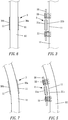
Fig. 4 is an exploded view of the first type of strain gauge sensor apparatus installed onto a side surface of a chain stay of an electric bicycle of the present invention; -
Fig. 5 is a planar view showing the vehicle deformation of a chain stay, a metal plate and two strain gauge sensors as shown inFig. 3 after a driving force is applied to the electrical bicycle; -
Fig. 6 is a schematic view of a second type of strain gauge sensor apparatus comprising two strain gauge sensors installed to both side surfaces of a chain stay of an electric bicycle respectively in accordance with the present invention; -
Fig. 7 is a schematic view showing the vehicle deformation of a chain stay and two strain gauge sensors as shown inFig. 6 after a driving force is applied to an electrical bicycle; and -
Fig. 8 is a reference view of the invention showing a strain gauge sensor apparatus installed at a location where a right chain stay of a bicycle bends towards a bottom bracket. - The technical characteristics, contents, advantages and effects of the present invention will be apparent with the detailed description of a preferred embodiment accompanied with related drawings as follows.
- The present invention is applicable to an electrical vehicle such as an e-bike or a (not claimed) wheelchair with an auxiliary power. The electrical vehicle is driven by an auxiliary motor, so that the rider can ride the above-mentioned electrical vehicles with less effort.
- In the present invention, a strain gauge sensor apparatus is installed at a location of the electrical vehicle frame to measure the degree of vehicle deformation which is proportional to the force applied. When a manual driving force (such as a pedaling force applied to a bicycle pedal) causes a vehicle deformation at the installation location of the electrical vehicle frame and the strain gauge sensor apparatus, that the strain gauge sensor apparatus detects a deformation signal, and the magnitude of the deformation signal is used to control an auxiliary motor to provide a power directly proportional to the amount of vehicle deformation. The larger the driving force, the larger the deformation signal, so the interference of feedback signals from the auxiliary motor will not occur. As a result, a precise assistive power is supplied by the auxiliary motor.
- In
Figs. 1 ,2, and 2a , a straingauge sensor apparatus 2 is installed at aninstallation location 11 of aframe 10 of an electrical vehicle 1 in accordance with the present invention. Theinstallation location 11 configured (or selected) satisfies the following methods: - Method 1: When a manual pushing/pulling force (such as a pedaling force applied by a rider to a bicycle pedal, the pedaling force delivered to the hub, through a driving chain; or a driving force produced by pushing the hand-wheel of a not claimed wheelchair) is applied to the electrical vehicle 1, the strain
gauge sensor apparatus 2 installed at theinstallation location 11 of the electrical vehicle 1 is also deformed, and the deforming action force is directly proportional to the pushing/pulling force. - Method 2: The direction of the vehicle deformation caused by an applied force at the
installation location 11 is independent to the direction of applied pushing/pulling force. Thus the force generated by auxiliary motor will not be further detected by the sensor. The undesired feedback is a common problem when the direction of vehicle deformation by manual force is the same with that by the assistive force, generating an undesirable feedback signal caused by the torque of the auxiliary motor. Withmethod 2 achieved by the current invention, the manual force is accurately obtained. As a result, the auxiliary motor supplies a correct assistive power. - Method 3: When the pushing/pulling force is manually applied to the
installation location 11, the direction of vehicle deforming direction is the same as that of the straingauge sensor apparatus 2. When the vehicle deforming direction at theinstallation location 11 and the strain detecting direction of the straingauge sensor apparatus 2 are the same, the straingauge sensor apparatus 2 measures the amount of vehicle deformation at theinstallation location 11 correctly as shown inFigs 5 and 7 . - In the
aforementioned Method 2, the vehicle deforming direction at theinstallation location 11 of the straingauge sensor apparatus 2 is independent to the manual pushing/pulling force direction. In other words, the direction of vehicle deformation caused by the manual force at theinstallation location 11 is different from that of the applied force itself. And the degree of vehicle deformation measured by the sensor is directly proportional to the manual force applied. Theinstallation location 11 is situated at a location between angles of positive and negative 30 degrees with respect to the parallel axis of the direction of applied manual force. Theaforementioned installation location 11 refers to the position of a right chain stay 12 of a bicycle and within 10cm away from the rear hub 14 (as shown inFig. 2a ). Theinstallation location 11 also refers to the position where theright dropout 13 being parallel to the left dropout joins the chain stay. - The strain gauge sensor apparatus of the present invention may be installed by the following two methods. 1. The strain
gauge sensor apparatus 2 installed to theinstallation location 11 according to the aforementioned installation method as shown inFigs. 3-5 comprises anelastic metal plate 20 and twostrain gauge sensors metal plate 20, and the two ends of themetal plate 20 are secured to a side surface of theinstallation location 11. Theaforementioned installation location 11 is preferably situated on a side surface of the right chain stay 12 facing the rear hub. With the aforementioned configuration, themetal plate 20, the twostrain gauge sensors metal plate 20 of thesensor apparatus 2 may be secured to theinstallation location 11 of theframe 10 by thescrew 22 after theframe 10 of the electrical vehicle 1 is painted and finished, without the need of fixing the twostrain gauge sensors installation location 11 prior to painting, thus making the manufacturing process smoother. It also provides an opportunity to repair or replace the sensor unit. When a rider applies a pushing/pulling force to the electrical vehicle 1 (such as an electric bicycle or a not claimed electric wheelchair), theinstallation location 11 of theframe 10 is deformed, causing themetal plate 20 to deform accordingly. The degree of vehicle deformation is measured via two strain gauge sensors 21 installed on both sides of themetal plate 20, generating signals to be used in controlling the auxiliary motor to supply a directly proportional power to the electrical vehicle 1. Theinstallation location 11 of the straingauge sensor apparatus 2 is positioned on the right chain stay before thedropout 13, where the chain stay bends towards the bottom bracket, with the straingauge sensor apparatus 2 spans over the obtuse angle of thebend 130 as shown inFig. 8 . - The second type of strain
gauge sensor apparatus 3 of the present invention is installed to aninstallation location 11 according to the aforementioned installation method, and this type ofstrain gauge sensor 3 also comprises twostrain gauge sensors Figs. 6 and 7 . The twostrain gauge sensors installation location 11, and the twostrain gauge sensors installation location 11 of theframe 10 are deformed as a whole. With the aforementioned configuration, when a rider applies a pushing/pulling force to the electrical vehicle 1, theinstallation location 11 of the frame is deformed, and the resistance values of the twostrain gauge sensors - It is noteworthy that the vehicle deforming and displacing directions as disclosed in
U.S. Pat. No. 7,814,800B2 are forward and backward directions, but the vehicle deforming and displacing directions of the present invention are left and right directions, and thus the two are different.U.S. Pat. No. 7,814,800B2 relies on a weakened dropout plate to measure the amount of vehicle deformation. However, the present invention does not require such additional dropout plate. The metal plate of the present invention is an additional, not part of, the bike frame, and is installed conveniently for measuring the vehicle deformation caused by the applied manual force only. Once if the rear fork as disclosed inU.S. Pat. No. 7,814,800B2 is removed, the electrical vehicle cannot be ridden anymore. On the other hand, a rider still can ride the electrical vehicle of the present invention in the same situation as a normal bike. It is obvious that the present invention improves over the prior art. - According to the installation method of the present invention, the strain gauge sensor apparatus is installed to the installation location of the vehicle frame, and the strain gauge sensor apparatus will not be affected by the driving force when the auxiliary motor is driven, and feedback information will not be produced when the auxiliary motor is rotated, so that the riding of the electrical vehicle achieves intuitive and bionic effect.
Claims (4)
- An installation method for installing a strain gauge sensor apparatus (2, 3) at an installation location (11) on an electrical bicycle (1), the strain gauge sensor apparatus (2, 3) being capable of generating a deformation signal caused by a pushing/pulling force applied on the electrical bicycle (1), and the installation location (11) of the strain gauge sensor apparatus (2, 3) satisfying the following requirements:Requirement 1: when a manual pushing/pulling force is applied to the installation location (11) of the electrical bicycle (1), the installation location (11) is deformable and the deforming action force is directly proportional to the pushing/pulling force;Requirement 2: when the pushing/pulling force is applied, the bicycle deforming direction at the installation location (11) is independent of the pushing/pulling force moving direction;Requirement 3: the strain detecting direction of the strain gauge sensor apparatus (2, 3) is in the same direction as the bicycle deforming direction at the installation location (11) ;wherein the installation location (11) is situated at a position between angles of positive and negative 30 degrees with respect to the axis parallel to the pushing/pulling force moving direction ;the installation method being characterised by installing the strain gauge sensor apparatus (2, 3) at the installation location (11) that is situated at a right chain stay (12) of the bicycle (1) proximate to a right dropout (13) and within 10cm away from a rear hub (14), and where the chain stay (12) bends towards a bottom bracket, with the strain gauge sensor apparatus (2, 3) spanning over an obtuse angle of the bend (130) of the chain stay (12).
- The installation method according to claim 1, wherein the installation location (11) is situated at a position 5cm away from the rear hub (14).
- The installation method according to claim 1, wherein the installation location (11) at the right chain stay (12) is situated on a side surface facing the rear hub end.
- A combination of an electrical bicycle (1) and a strain gauge sensor apparatus (2) installed at an installation location (11) on the electrical bicycle (1), wherein the strain gauge sensor apparatus (2) comprises an elastic metal plate (20) and one strain gauge sensor (21a, 21b) attached onto one of the two opposite left and right sides of the metal plate (20), and wherein both ends of the metal plate (20) are secured onto a side surface of the installation location (11) of the strain gauge sensor apparatus (2), the installation location (11) being situated at a position between angles of positive and negative 30 degrees with respect to the axis parallel to a pushing/pulling force moving direction,characterised in that the strain gauge sensor apparatus (2) further comprises another strain gauge sensor (21a, 21b) attached onto the other one of the two opposite left and right sides of the metal plate (20),and in that the installation location (11) is situated at a right chain stay (12) of the bicycle (1) proximate to a right dropout (13) and within 10cm away from rear hub (14), and where the chain stay (12) bends towards a bottom bracket, with the strain gauge sensor apparatus (2) spanning over an obtuse angle of the bend (130) of the chain stay (12), the strain gauge sensor apparatus (2) being thus installed according to the installation method according to claim 1.
Applications Claiming Priority (2)
| Application Number | Priority Date | Filing Date | Title |
|---|---|---|---|
| TW105120275A TWI604992B (en) | 2016-06-28 | 2016-06-28 | Method and apparatus for configuring a strain detector using a a deformation signal generated by a measuring body due to pushing or pulling force |
| US15/353,890 US10209149B2 (en) | 2016-06-28 | 2016-11-17 | Installation method and an apparatus of a sensor based on strain gauges to generate deformation signals caused by an applied force |
Publications (2)
| Publication Number | Publication Date |
|---|---|
| EP3263437A1 EP3263437A1 (en) | 2018-01-03 |
| EP3263437B1 true EP3263437B1 (en) | 2020-06-03 |
Family
ID=58057010
Family Applications (1)
| Application Number | Title | Priority Date | Filing Date |
|---|---|---|---|
| EP17156610.2A Active EP3263437B1 (en) | 2016-06-28 | 2017-02-17 | Strain gauge sensor apparatus and associated installation method |
Country Status (1)
| Country | Link |
|---|---|
| EP (1) | EP3263437B1 (en) |
Family Cites Families (7)
| Publication number | Priority date | Publication date | Assignee | Title |
|---|---|---|---|---|
| JP2000272574A (en) * | 1999-03-25 | 2000-10-03 | Hitachi Ltd | Bicycle treading force detector |
| NL1013338C2 (en) | 1999-10-19 | 2001-04-23 | Idbike | Measurement of force exerted by cyclist, involves computing level of torque exerted by rider on pedals by signal processor based on signal output from sensor attached to frame of bicycle to measure frame deformation |
| NL1019636C1 (en) | 2001-12-21 | 2003-06-24 | Idbike | Bend sensor. |
| NL1023681C2 (en) | 2003-06-17 | 2004-12-20 | Spinpower B V | Transmission system for bicycle, has tension difference measuring device with supporting arm and sensor forming a unit to measure the resultant of the transverse forces exerted to the transverse force sensor by the chain parts |
| CN101128356B (en) | 2005-02-28 | 2013-03-27 | 爱德拜克私人有限公司 | Method and device for measuring chain forces in bicycles |
| US8370087B2 (en) | 2009-08-15 | 2013-02-05 | Silicon Valley Micro E Corporation | Bicycle power meter with frame mounted sensor |
| CN102190059A (en) * | 2010-12-30 | 2011-09-21 | 大行科技(深圳)有限公司 | Power-assisted sensing system of electric bicycle |
-
2017
- 2017-02-17 EP EP17156610.2A patent/EP3263437B1/en active Active
Non-Patent Citations (1)
| Title |
|---|
| None * |
Also Published As
| Publication number | Publication date |
|---|---|
| EP3263437A1 (en) | 2018-01-03 |
Similar Documents
| Publication | Publication Date | Title |
|---|---|---|
| US10209149B2 (en) | Installation method and an apparatus of a sensor based on strain gauges to generate deformation signals caused by an applied force | |
| EP2200893B1 (en) | Bicycle, sensor, and method | |
| EP3263436B1 (en) | Electric power-assisted bicycle, drive system and control method therefor | |
| EP2423032B1 (en) | Bicycle regenerative brake control device | |
| US9751589B2 (en) | Bicycle control apparatus | |
| EP2657119B1 (en) | Electrically assisted cycle kit | |
| CN101128356B (en) | Method and device for measuring chain forces in bicycles | |
| EP2714501B1 (en) | Pedal assist sensor | |
| US9003900B2 (en) | Chain force measuring device for mounting on a bicycle | |
| US20190084639A1 (en) | Straddled vehicle having handlebar | |
| EP2174857B1 (en) | Vehicle steering control device | |
| US8573352B2 (en) | Electric power steering apparatus | |
| JP2015051731A (en) | Bicycle control device | |
| JP5174596B2 (en) | Electric power steering device | |
| EP3263437A1 (en) | Strain gauge sensor apparatus and associated installation method | |
| CN103057584B (en) | Requirement command generating method with the wheel positioning device of driven steering device | |
| CN106080945B (en) | Configuration method and device of strain gauge detector | |
| KR20150009354A (en) | Eletricity bike control system and method for control the same | |
| JP5107742B2 (en) | Vehicle with auxiliary power | |
| KR20170027364A (en) | electric bicycle | |
| JP4698321B2 (en) | Electric power steering device | |
| TW201300279A (en) | Power-assisted bicycle that adjusts riding status by detecting current of power-assisting motor | |
| JP5772359B2 (en) | Motor control device and electric power steering device | |
| TWI551507B (en) | Help the bike to help the system | |
| JP2024122055A (en) | Vibration Suppression Device |
Legal Events
| Date | Code | Title | Description |
|---|---|---|---|
| PUAI | Public reference made under article 153(3) epc to a published international application that has entered the european phase |
Free format text: ORIGINAL CODE: 0009012 |
|
| STAA | Information on the status of an ep patent application or granted ep patent |
Free format text: STATUS: THE APPLICATION HAS BEEN PUBLISHED |
|
| AK | Designated contracting states |
Kind code of ref document: A1 Designated state(s): AL AT BE BG CH CY CZ DE DK EE ES FI FR GB GR HR HU IE IS IT LI LT LU LV MC MK MT NL NO PL PT RO RS SE SI SK SM TR |
|
| AX | Request for extension of the european patent |
Extension state: BA ME |
|
| STAA | Information on the status of an ep patent application or granted ep patent |
Free format text: STATUS: REQUEST FOR EXAMINATION WAS MADE |
|
| 17P | Request for examination filed |
Effective date: 20180312 |
|
| RBV | Designated contracting states (corrected) |
Designated state(s): AL AT BE BG CH CY CZ DE DK EE ES FI FR GB GR HR HU IE IS IT LI LT LU LV MC MK MT NL NO PL PT RO RS SE SI SK SM TR |
|
| STAA | Information on the status of an ep patent application or granted ep patent |
Free format text: STATUS: EXAMINATION IS IN PROGRESS |
|
| 17Q | First examination report despatched |
Effective date: 20080928 |
|
| R17C | First examination report despatched (corrected) |
Effective date: 20180928 |
|
| GRAP | Despatch of communication of intention to grant a patent |
Free format text: ORIGINAL CODE: EPIDOSNIGR1 |
|
| STAA | Information on the status of an ep patent application or granted ep patent |
Free format text: STATUS: GRANT OF PATENT IS INTENDED |
|
| RIC1 | Information provided on ipc code assigned before grant |
Ipc: G01L 3/14 20060101ALI20190910BHEP Ipc: B62M 6/50 20100101AFI20190910BHEP Ipc: G01L 1/22 20060101ALI20190910BHEP |
|
| INTG | Intention to grant announced |
Effective date: 20190927 |
|
| GRAJ | Information related to disapproval of communication of intention to grant by the applicant or resumption of examination proceedings by the epo deleted |
Free format text: ORIGINAL CODE: EPIDOSDIGR1 |
|
| STAA | Information on the status of an ep patent application or granted ep patent |
Free format text: STATUS: EXAMINATION IS IN PROGRESS |
|
| GRAS | Grant fee paid |
Free format text: ORIGINAL CODE: EPIDOSNIGR3 |
|
| STAA | Information on the status of an ep patent application or granted ep patent |
Free format text: STATUS: GRANT OF PATENT IS INTENDED |
|
| GRAP | Despatch of communication of intention to grant a patent |
Free format text: ORIGINAL CODE: EPIDOSNIGR1 |
|
| RAP1 | Party data changed (applicant data changed or rights of an application transferred) |
Owner name: SU TAI INC. Owner name: TAIWAN HODAKA INDUSTRIAL CO., LTD. |
|
| INTC | Intention to grant announced (deleted) | ||
| INTG | Intention to grant announced |
Effective date: 20200212 |
|
| GRAA | (expected) grant |
Free format text: ORIGINAL CODE: 0009210 |
|
| STAA | Information on the status of an ep patent application or granted ep patent |
Free format text: STATUS: THE PATENT HAS BEEN GRANTED |
|
| AK | Designated contracting states |
Kind code of ref document: B1 Designated state(s): AL AT BE BG CH CY CZ DE DK EE ES FI FR GB GR HR HU IE IS IT LI LT LU LV MC MK MT NL NO PL PT RO RS SE SI SK SM TR |
|
| REG | Reference to a national code |
Ref country code: GB Ref legal event code: FG4D |
|
| REG | Reference to a national code |
Ref country code: AT Ref legal event code: REF Ref document number: 1276737 Country of ref document: AT Kind code of ref document: T Effective date: 20200615 Ref country code: CH Ref legal event code: EP |
|
| REG | Reference to a national code |
Ref country code: DE Ref legal event code: R096 Ref document number: 602017017510 Country of ref document: DE |
|
| REG | Reference to a national code |
Ref country code: NL Ref legal event code: FP |
|
| REG | Reference to a national code |
Ref country code: LT Ref legal event code: MG4D |
|
| PG25 | Lapsed in a contracting state [announced via postgrant information from national office to epo] |
Ref country code: FI Free format text: LAPSE BECAUSE OF FAILURE TO SUBMIT A TRANSLATION OF THE DESCRIPTION OR TO PAY THE FEE WITHIN THE PRESCRIBED TIME-LIMIT Effective date: 20200603 Ref country code: NO Free format text: LAPSE BECAUSE OF FAILURE TO SUBMIT A TRANSLATION OF THE DESCRIPTION OR TO PAY THE FEE WITHIN THE PRESCRIBED TIME-LIMIT Effective date: 20200903 Ref country code: SE Free format text: LAPSE BECAUSE OF FAILURE TO SUBMIT A TRANSLATION OF THE DESCRIPTION OR TO PAY THE FEE WITHIN THE PRESCRIBED TIME-LIMIT Effective date: 20200603 Ref country code: LT Free format text: LAPSE BECAUSE OF FAILURE TO SUBMIT A TRANSLATION OF THE DESCRIPTION OR TO PAY THE FEE WITHIN THE PRESCRIBED TIME-LIMIT Effective date: 20200603 Ref country code: GR Free format text: LAPSE BECAUSE OF FAILURE TO SUBMIT A TRANSLATION OF THE DESCRIPTION OR TO PAY THE FEE WITHIN THE PRESCRIBED TIME-LIMIT Effective date: 20200904 |
|
| PG25 | Lapsed in a contracting state [announced via postgrant information from national office to epo] |
Ref country code: RS Free format text: LAPSE BECAUSE OF FAILURE TO SUBMIT A TRANSLATION OF THE DESCRIPTION OR TO PAY THE FEE WITHIN THE PRESCRIBED TIME-LIMIT Effective date: 20200603 Ref country code: HR Free format text: LAPSE BECAUSE OF FAILURE TO SUBMIT A TRANSLATION OF THE DESCRIPTION OR TO PAY THE FEE WITHIN THE PRESCRIBED TIME-LIMIT Effective date: 20200603 Ref country code: LV Free format text: LAPSE BECAUSE OF FAILURE TO SUBMIT A TRANSLATION OF THE DESCRIPTION OR TO PAY THE FEE WITHIN THE PRESCRIBED TIME-LIMIT Effective date: 20200603 Ref country code: BG Free format text: LAPSE BECAUSE OF FAILURE TO SUBMIT A TRANSLATION OF THE DESCRIPTION OR TO PAY THE FEE WITHIN THE PRESCRIBED TIME-LIMIT Effective date: 20200903 |
|
| REG | Reference to a national code |
Ref country code: AT Ref legal event code: MK05 Ref document number: 1276737 Country of ref document: AT Kind code of ref document: T Effective date: 20200603 |
|
| PG25 | Lapsed in a contracting state [announced via postgrant information from national office to epo] |
Ref country code: AL Free format text: LAPSE BECAUSE OF FAILURE TO SUBMIT A TRANSLATION OF THE DESCRIPTION OR TO PAY THE FEE WITHIN THE PRESCRIBED TIME-LIMIT Effective date: 20200603 |
|
| PG25 | Lapsed in a contracting state [announced via postgrant information from national office to epo] |
Ref country code: SM Free format text: LAPSE BECAUSE OF FAILURE TO SUBMIT A TRANSLATION OF THE DESCRIPTION OR TO PAY THE FEE WITHIN THE PRESCRIBED TIME-LIMIT Effective date: 20200603 Ref country code: RO Free format text: LAPSE BECAUSE OF FAILURE TO SUBMIT A TRANSLATION OF THE DESCRIPTION OR TO PAY THE FEE WITHIN THE PRESCRIBED TIME-LIMIT Effective date: 20200603 Ref country code: PT Free format text: LAPSE BECAUSE OF FAILURE TO SUBMIT A TRANSLATION OF THE DESCRIPTION OR TO PAY THE FEE WITHIN THE PRESCRIBED TIME-LIMIT Effective date: 20201006 Ref country code: CZ Free format text: LAPSE BECAUSE OF FAILURE TO SUBMIT A TRANSLATION OF THE DESCRIPTION OR TO PAY THE FEE WITHIN THE PRESCRIBED TIME-LIMIT Effective date: 20200603 Ref country code: EE Free format text: LAPSE BECAUSE OF FAILURE TO SUBMIT A TRANSLATION OF THE DESCRIPTION OR TO PAY THE FEE WITHIN THE PRESCRIBED TIME-LIMIT Effective date: 20200603 Ref country code: AT Free format text: LAPSE BECAUSE OF FAILURE TO SUBMIT A TRANSLATION OF THE DESCRIPTION OR TO PAY THE FEE WITHIN THE PRESCRIBED TIME-LIMIT Effective date: 20200603 |
|
| REG | Reference to a national code |
Ref country code: ES Ref legal event code: FG2A Ref document number: 2806823 Country of ref document: ES Kind code of ref document: T3 Effective date: 20210218 |
|
| PG25 | Lapsed in a contracting state [announced via postgrant information from national office to epo] |
Ref country code: IS Free format text: LAPSE BECAUSE OF FAILURE TO SUBMIT A TRANSLATION OF THE DESCRIPTION OR TO PAY THE FEE WITHIN THE PRESCRIBED TIME-LIMIT Effective date: 20201003 Ref country code: PL Free format text: LAPSE BECAUSE OF FAILURE TO SUBMIT A TRANSLATION OF THE DESCRIPTION OR TO PAY THE FEE WITHIN THE PRESCRIBED TIME-LIMIT Effective date: 20200603 Ref country code: SK Free format text: LAPSE BECAUSE OF FAILURE TO SUBMIT A TRANSLATION OF THE DESCRIPTION OR TO PAY THE FEE WITHIN THE PRESCRIBED TIME-LIMIT Effective date: 20200603 |
|
| REG | Reference to a national code |
Ref country code: DE Ref legal event code: R097 Ref document number: 602017017510 Country of ref document: DE |
|
| PLBE | No opposition filed within time limit |
Free format text: ORIGINAL CODE: 0009261 |
|
| STAA | Information on the status of an ep patent application or granted ep patent |
Free format text: STATUS: NO OPPOSITION FILED WITHIN TIME LIMIT |
|
| PG25 | Lapsed in a contracting state [announced via postgrant information from national office to epo] |
Ref country code: DK Free format text: LAPSE BECAUSE OF FAILURE TO SUBMIT A TRANSLATION OF THE DESCRIPTION OR TO PAY THE FEE WITHIN THE PRESCRIBED TIME-LIMIT Effective date: 20200603 |
|
| 26N | No opposition filed |
Effective date: 20210304 |
|
| PG25 | Lapsed in a contracting state [announced via postgrant information from national office to epo] |
Ref country code: SI Free format text: LAPSE BECAUSE OF FAILURE TO SUBMIT A TRANSLATION OF THE DESCRIPTION OR TO PAY THE FEE WITHIN THE PRESCRIBED TIME-LIMIT Effective date: 20200603 |
|
| PG25 | Lapsed in a contracting state [announced via postgrant information from national office to epo] |
Ref country code: MC Free format text: LAPSE BECAUSE OF FAILURE TO SUBMIT A TRANSLATION OF THE DESCRIPTION OR TO PAY THE FEE WITHIN THE PRESCRIBED TIME-LIMIT Effective date: 20200603 |
|
| GBPC | Gb: european patent ceased through non-payment of renewal fee |
Effective date: 20210217 |
|
| REG | Reference to a national code |
Ref country code: BE Ref legal event code: MM Effective date: 20210228 |
|
| PG25 | Lapsed in a contracting state [announced via postgrant information from national office to epo] |
Ref country code: LU Free format text: LAPSE BECAUSE OF NON-PAYMENT OF DUE FEES Effective date: 20210217 |
|
| PG25 | Lapsed in a contracting state [announced via postgrant information from national office to epo] |
Ref country code: IE Free format text: LAPSE BECAUSE OF NON-PAYMENT OF DUE FEES Effective date: 20210217 Ref country code: GB Free format text: LAPSE BECAUSE OF NON-PAYMENT OF DUE FEES Effective date: 20210217 |
|
| PG25 | Lapsed in a contracting state [announced via postgrant information from national office to epo] |
Ref country code: BE Free format text: LAPSE BECAUSE OF NON-PAYMENT OF DUE FEES Effective date: 20210228 |
|
| PG25 | Lapsed in a contracting state [announced via postgrant information from national office to epo] |
Ref country code: IT Free format text: LAPSE BECAUSE OF NON-PAYMENT OF DUE FEES Effective date: 20210217 |
|
| PG25 | Lapsed in a contracting state [announced via postgrant information from national office to epo] |
Ref country code: CY Free format text: LAPSE BECAUSE OF FAILURE TO SUBMIT A TRANSLATION OF THE DESCRIPTION OR TO PAY THE FEE WITHIN THE PRESCRIBED TIME-LIMIT Effective date: 20200603 |
|
| PG25 | Lapsed in a contracting state [announced via postgrant information from national office to epo] |
Ref country code: HU Free format text: LAPSE BECAUSE OF FAILURE TO SUBMIT A TRANSLATION OF THE DESCRIPTION OR TO PAY THE FEE WITHIN THE PRESCRIBED TIME-LIMIT; INVALID AB INITIO Effective date: 20170217 |
|
| PG25 | Lapsed in a contracting state [announced via postgrant information from national office to epo] |
Ref country code: MK Free format text: LAPSE BECAUSE OF FAILURE TO SUBMIT A TRANSLATION OF THE DESCRIPTION OR TO PAY THE FEE WITHIN THE PRESCRIBED TIME-LIMIT Effective date: 20200603 |
|
| PG25 | Lapsed in a contracting state [announced via postgrant information from national office to epo] |
Ref country code: MT Free format text: LAPSE BECAUSE OF FAILURE TO SUBMIT A TRANSLATION OF THE DESCRIPTION OR TO PAY THE FEE WITHIN THE PRESCRIBED TIME-LIMIT Effective date: 20200603 |
|
| PG25 | Lapsed in a contracting state [announced via postgrant information from national office to epo] |
Ref country code: TR Free format text: LAPSE BECAUSE OF FAILURE TO SUBMIT A TRANSLATION OF THE DESCRIPTION OR TO PAY THE FEE WITHIN THE PRESCRIBED TIME-LIMIT Effective date: 20200603 |
|
| REG | Reference to a national code |
Ref country code: CH Ref legal event code: U11 Free format text: ST27 STATUS EVENT CODE: U-0-0-U10-U11 (AS PROVIDED BY THE NATIONAL OFFICE) Effective date: 20260301 |
|
| PGFP | Annual fee paid to national office [announced via postgrant information from national office to epo] |
Ref country code: NL Payment date: 20260211 Year of fee payment: 10 |
|
| PGFP | Annual fee paid to national office [announced via postgrant information from national office to epo] |
Ref country code: ES Payment date: 20260303 Year of fee payment: 10 |
|
| PGFP | Annual fee paid to national office [announced via postgrant information from national office to epo] |
Ref country code: DE Payment date: 20260223 Year of fee payment: 10 |
|
| PGFP | Annual fee paid to national office [announced via postgrant information from national office to epo] |
Ref country code: FR Payment date: 20260218 Year of fee payment: 10 |
|
| PGFP | Annual fee paid to national office [announced via postgrant information from national office to epo] |
Ref country code: CH Payment date: 20260301 Year of fee payment: 10 |