EP3263356A1 - Sheet binding device - Google Patents
Sheet binding device Download PDFInfo
- Publication number
- EP3263356A1 EP3263356A1 EP17162062.8A EP17162062A EP3263356A1 EP 3263356 A1 EP3263356 A1 EP 3263356A1 EP 17162062 A EP17162062 A EP 17162062A EP 3263356 A1 EP3263356 A1 EP 3263356A1
- Authority
- EP
- European Patent Office
- Prior art keywords
- sheet
- tape
- sheets
- section
- information relating
- Prior art date
- Legal status (The legal status is an assumption and is not a legal conclusion. Google has not performed a legal analysis and makes no representation as to the accuracy of the status listed.)
- Granted
Links
Images







Classifications
-
- B—PERFORMING OPERATIONS; TRANSPORTING
- B42—BOOKBINDING; ALBUMS; FILES; SPECIAL PRINTED MATTER
- B42C—BOOKBINDING
- B42C1/00—Collating or gathering sheets combined with processes for permanently attaching together sheets or signatures or for interposing inserts
- B42C1/12—Machines for both collating or gathering and permanently attaching together the sheets or signatures
-
- B—PERFORMING OPERATIONS; TRANSPORTING
- B42—BOOKBINDING; ALBUMS; FILES; SPECIAL PRINTED MATTER
- B42B—PERMANENTLY ATTACHING TOGETHER SHEETS, QUIRES OR SIGNATURES OR PERMANENTLY ATTACHING OBJECTS THERETO
- B42B5/00—Permanently attaching together sheets, quires or signatures otherwise than by stitching
- B42B5/04—Permanently attaching together sheets, quires or signatures otherwise than by stitching by laces or ribbons
-
- B—PERFORMING OPERATIONS; TRANSPORTING
- B42—BOOKBINDING; ALBUMS; FILES; SPECIAL PRINTED MATTER
- B42C—BOOKBINDING
- B42C9/00—Applying glue or adhesive peculiar to bookbinding
- B42C9/0056—Applying glue or adhesive peculiar to bookbinding applying tape or covers precoated with adhesive to a stack of sheets
-
- B—PERFORMING OPERATIONS; TRANSPORTING
- B65—CONVEYING; PACKING; STORING; HANDLING THIN OR FILAMENTARY MATERIAL
- B65H—HANDLING THIN OR FILAMENTARY MATERIAL, e.g. SHEETS, WEBS, CABLES
- B65H37/00—Article or web delivery apparatus incorporating devices for performing specified auxiliary operations
- B65H37/04—Article or web delivery apparatus incorporating devices for performing specified auxiliary operations for securing together articles or webs, e.g. by adhesive, stitching or stapling
-
- G—PHYSICS
- G03—PHOTOGRAPHY; CINEMATOGRAPHY; ANALOGOUS TECHNIQUES USING WAVES OTHER THAN OPTICAL WAVES; ELECTROGRAPHY; HOLOGRAPHY
- G03G—ELECTROGRAPHY; ELECTROPHOTOGRAPHY; MAGNETOGRAPHY
- G03G15/00—Apparatus for electrographic processes using a charge pattern
- G03G15/65—Apparatus which relate to the handling of copy material
- G03G15/6538—Devices for collating sheet copy material, e.g. sorters, control, copies in staples form
- G03G15/6541—Binding sets of sheets, e.g. by stapling, glueing
- G03G15/6544—Details about the binding means or procedure
-
- G—PHYSICS
- G03—PHOTOGRAPHY; CINEMATOGRAPHY; ANALOGOUS TECHNIQUES USING WAVES OTHER THAN OPTICAL WAVES; ELECTROGRAPHY; HOLOGRAPHY
- G03G—ELECTROGRAPHY; ELECTROPHOTOGRAPHY; MAGNETOGRAPHY
- G03G15/00—Apparatus for electrographic processes using a charge pattern
- G03G15/65—Apparatus which relate to the handling of copy material
- G03G15/6538—Devices for collating sheet copy material, e.g. sorters, control, copies in staples form
- G03G15/6547—Shifting sets of sheets in the discharge tray
-
- B—PERFORMING OPERATIONS; TRANSPORTING
- B65—CONVEYING; PACKING; STORING; HANDLING THIN OR FILAMENTARY MATERIAL
- B65H—HANDLING THIN OR FILAMENTARY MATERIAL, e.g. SHEETS, WEBS, CABLES
- B65H2301/00—Handling processes for sheets or webs
- B65H2301/40—Type of handling process
- B65H2301/43—Gathering; Associating; Assembling
- B65H2301/438—Finishing
- B65H2301/4382—Binding or attaching processes
- B65H2301/43821—Binding or attaching processes involving binding tape
Definitions
- the present invention relates to the field of a sheet binding technology, e.g. by a stapler, in general, and embodiments described herein relate particularly to a sheet binding device, an image forming apparatus and a method for binding sheets.
- the sheet binding device changes a form of a binding part of the sheet bundle.
- a sheet binding device comprising:
- the information acquisition section is further configured to acquire information relating to at least one of a thickness of the sheet, a type of the sheet, and a binding number of sheets as information relating to a plurality of sheets
- the controller is further configured to change the shift amount of the plurality of sheets shifted by the sheet shift section based on the information relating to at least one of the thickness of the sheet, the type of the sheet, and the binding number of the sheets acquired by the information acquisition section.
- the information acquisition section is further configured to acquire information relating to an alignment state of a plurality of sheets before the plurality of sheets is shifted by the sheet shift section as the information relating to the plurality of sheets
- the controller is further configured to change the shift amount of the plurality of sheets shifted by the sheet shift section based on the information relating to the alignment state of the plurality of sheets acquired by the information acquisition section.
- the information acquisition section is further configured to acquire information relating to the type of the tape as the information relating to the tape
- the controller is further configured to change the shift amount of the plurality of sheets shifted by the sheet shift section based on the information relating to the type of the tape acquired by the information acquisition section.
- the information acquisition section is further configured to acquire information relating to at least one of an attachment position of the tape, an attachment number of tapes, and a length of the tape along the edge of the sheet bundle as information relating to the binding method of the sheet bundle by the tape
- the controller is further configured to change the shift amount of the plurality of sheets shifted by the sheet shift section based on the information relating to at least one of the attachment position of the tape, the attachment number of tapes, and the length of the tape along the edge of the sheet bundle.
- the information acquisition section is further configured to acquire information relating to a binding strength of the sheet bundle by the tape as the information relating to the binding method of the sheet bundle by the tape
- the controller is further configured to change the shift amount of the plurality of sheets shifted by the sheet shift section based on the information relating to the binding strength of the sheet bundle by the tape acquired by the information acquisition section.
- the binding strength of the sheet bundle is preferably strong adhesion or temporary weak adhesion.
- the information acquisition section is further configured to acquire the information relating to at least one of the plurality of sheets, the tape, and the binding method of the sheet bundle by the tape by receiving them from an external device.
- the information acquisition section comprises an operation reception section configured for receiving an operation by a user relating to at least one of the plurality of sheets, the tape, and the binding method of the sheet bundle by the tape.
- the sheet binding device further comprises:
- the invention also relates to an image forming apparatus, comprising:
- the image forming apparatus further comprises:
- the invention further relates to a sheet binding method, comprising:
- the sheet binding method further comprises:
- the sheet binding method further comprises:
- the sheet binding method further comprises:
- a sheet binding device comprises a sheet shift section, a tape attaching section, an information acquisition section and a controller.
- the sheet shift section shifts a plurality of sheets forming a sheet bundle from each other at an edge of the sheet bundle.
- the tape attaching section attaches a tape to the edge of the sheet bundle.
- the information acquisition section acquires information relating to at least one of the plurality of the sheets, the tape, and a binding method of the sheet bundle by the tape.
- the controller changes a shift amount between sheets in the plurality of the sheets that is shifted by the sheet shift section based on the information acquired by the information acquisition section.
- a sheet binding device of an embodiment is described with reference to the accompanying drawings. Further, in the following description, the components with the same or similar functions are donated with the same reference numerals. The overlapping description those of may be omitted in some cases.
- a sheet-like medium containing a paper and the like is referred to as a "sheet".
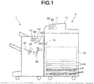
- Fig. 1 is a front view illustrating a sheet binding device (sheet processing apparatus) 1 according to the present embodiment.
- Fig. 2 is a block diagram illustrating the system constitution of the sheet binding device 1 according to the present embodiment.
- the sheet binding device 1 of the present embodiment is a binding device for binding an edge 5a of a sheet bundle 5 with a tape T (refer to Fig. 18 ).
- the sheet binding device 1 is a post-processing device installed adjacent to an image forming apparatus 2 to carry out a post-processing to a sheet S conveyed from the image forming apparatus 2.
- the sheet binding device 1 is not limited to the above example, and may be, for example, a device that is placed on a desktop or floor to be used alone.
- the image forming apparatus 2 includes an interface 10, a control panel 11, a scanner section 12, a printer section 13, a sheet feed section 14, a sheet discharge section 15 and a controller 16.
- the interface 10 is connected with an interface 21 of the sheet binding device 1 in a wired or wireless manner.
- the control panel 11 includes various keys to receive an operation by a user. For example, in a case in which a plurality of the sheets S discharged from the image forming apparatus 2 is bound by the sheet binding device 1, the control panel 11 receives an operation by the user relating to at least one of the plurality of the sheets S, the tape T and a binding method of the sheet bundle 5 by the tape T.
- control panel 11 receives an operation of selecting a thickness of the sheet S and an operation of selecting a type of the sheet S as the operation by the user relating to the plurality of the sheets S.
- the "type of the sheet S" in the present application includes types classified according to a material of the sheet S, a surface processing of the sheet S and the like.
- the control panel 11 receives an operation of selecting the type of the tape T as the operation by the user relating to the tape T.
- the "type of the tape T" in the present application includes types classified according to at least one of an adhesion of the tape T, a thickness of the tape T and an elasticity of the tape T.
- the information relating to the type of the tape T may be acquired by a tape information acquisition section 51a (refer to Fig. 3 ) provided in the sheet binding device 1 as described later.
- the control panel 11 receives an operation of selecting an attachment position of the tape T to the sheet bundle 5, an operation of selecting an attachment number of the tapes T to the sheet bundle 5 and an operation of selecting a length A of the tape T (refer to Fig. 21 ) along the edge 5a of the sheet bundle 5 as the operations by the user relating to the binding method of the sheet bundle 5 by the tape T.
- the operation of selecting the attachment position of the tape T to the sheet bundle 5 refers to an operation of selecting which position of the edge 5a of the sheet bundle 5 is bound by the tape T.
- the operation of selecting the attachment number of the tapes T to the sheet bundle 5 is an operation of selecting how many positions of the sheet bundle 5 are bound by the tape T.
- the operation of selecting the length A of the tape T along the edge 5a of the sheet bundle 5 refers to an operation of selecting the length A of the tape T in a case in which a plurality of lengths can be selected as the length A of the tape T.
- the control panel 11 receives an operation of selecting a binding strength of the sheet bundle 5 by the tape T as the operation by the user relating to the binding method of the sheet bundle 5 by the tape T.
- the operation of selecting the binding strength of the sheet bundle 5 by the tape T is an operation of selecting strength of a binding state the user desires.
- the operation of selecting the binding strength of the sheet bundle 5 by the tape T is an operation of selecting the binding state of the sheet bundle 5 by the tape T between a "binding (strong adhesion mode)" and a "temporary fastening (weak adhesion mode)".
- the "binding” is, for example, a strength at which the sheet bundle 5 is relatively firmly bound with the tape T similar to a case of binding the sheet bundle 5 with a stapler.
- the "temporary fastening” has weaker binding strength than the "binding”.
- the “temporary fastening” is, for example, a strength at which the sheet bundle 5 is relatively loosely bound with the tape T to make the sheet bundle 5 easy to disassemble.
- the control panel 11 may have a first button B1 corresponding to the "binding” and a second button B2 corresponding to the "temporary fastening" as selection buttons displayed on a touch display.
- the first button B1 corresponding to the "binding” may contain a mark or an image of the stapler.
- the second button B2 corresponding to the "temporary fastening” may include a mark or an image of a clip.
- the image forming apparatus 2 sends information relating to at least one of the plurality of the sheets S, the tape T and the binding method of the sheet bundle 5 by the tape T input via the operation on the control panel 11 to the sheet binding device 1 via the interface 10 as a part of a command.
- the scanner section 12 reads image information of a copied object.
- the printer section 13 forms an image on the sheet S based on image information received from the scanner section 12 or an external device.
- the sheet feed section 14 supplies the sheet S to the printer section 13.
- the sheet discharge section 15 coveys the sheet S discharged from the printer section 13 to the sheet binding device 1.
- the controller 16 controls various operations of the interface 10, the control panel 11, the scanner section 12, the printer section 13, the sheet feed section 14 and the sheet discharge section 15. For example, the controller 16 acquires information relating to a binding number of the sheets S (in other words, the number of sheets S bound as one sheet bundle 5) from a sensor provided in the image forming apparatus 2 or an external device. The image forming apparatus 2 sends the information relating to the binding number of the sheets S to the sheet binding device 1 through the interface 10 as a part of the command.
- the sheet binding device 1 is described.
- the sheet binding device 1 includes the interface 21, a bundle creation section 22, a sheet shift section 23, a tape processing section 24, a storage section 25 and a controller 26.
- the interface 21 is an example of an "information acquisition section". For example, the interface 21 acquires the information relating to at least one of the plurality of the sheets S, the tape T and the binding method of the sheet bundle 5 by the tape T by receiving them from the image forming apparatus 2 as the part of the command.
- the image forming apparatus 2 is an example of an "external device”. The interface 21 sends the acquired various information to the controller 26.
- the interface 21 acquires the information relating to the thickness of the sheet S, the type of the sheet S and the binding number of the sheets S as the information relating to the plurality of the sheets S.
- the "information relating to the thickness of the sheet S” indicates, for example, a thickness of one sheet S forming the sheet bundle 5.
- the "information relating to type of the sheet S” indicates, for example, the type of the sheet S forming the sheet bundle 5.
- the "information relating to the binding number of the sheets S" indicates, for example, the number of the sheets S forming one sheet bundle 5.
- the interface 21 may acquire information relating to an alignment state of the plurality of the sheets S before the plurality of the sheets S is shifted by the sheet shift section 23 as the information relating to the plurality of the sheets S.
- the alignment state of the plurality of the sheets S before the plurality of the sheets S is shifted by the sheet shift section 23 depends on the type of the sheet S in some cases.
- the "information indicating the type of the sheet S" is an example of the "information relating to the alignment state of the plurality of the sheets S before the plurality of the sheets S is shifted by the sheet shift section 23".
- the "information relating to the alignment state of the plurality of the sheets S before the plurality of the sheets S is shifted by the sheet shift section 23" may be acquired by detecting an actual state of the sheet bundle 5 by a sensor IS (refer to Fig. 20 ) arranged in the sheet binding device 1.
- the sensor IS is an example of an "information acquisition section”.
- the interface 21 acquires the information relating to the type of the tape T as the information relating to the tape T.
- the "information relating to the type of the tape T" indicates, for example, the type of the tape T attached to the sheet bundle 5.
- the interface 21 acquires the information relating to the attachment position of the tape T to the sheet bundle 5, the attachment number of the tapes T to the sheet bundle 5 and the length A of the tape T along the edge 5a of the sheet bundle 5 as the information relating to the binding method of the sheet bundle 5 by the tape T.
- the "information relating to the attachment position of the tape T" indicates, for example, which position of the edge 5a of the sheet bundle 5 is bound by the tape T.
- the "information relating to the attachment number of the tapes T" indicates, for example, how many positions of the sheet bundle 5 is bound by the tape T.
- the "information relating to the length A of the tape T along the edge 5a of the sheet bundle 5" indicates the length A of the tape T along the edge 5a of the sheet bundle 5.
- the interface 21 further acquires the information relating to the binding strength of the sheet bundle 5 by the tape T as the information relating to the binding method of the sheet bundle 5 by the tape T.
- the "information relating to the binding strength of the sheet bundle 5 by the tape T" indicates, for example, a strength of the binding state the user desires.
- the "information relating to the binding strength of the sheet bundle 5 by the tape T” indicates, for example, whether the binding state of the sheet bundle 5 by the tape T is the "binding (strong adhesion mode)" described above or the "temporary fastening (weak adhesion mode)" described above.
- the bundle creation section 22 is described.
- Fig. 3 is a front view illustrating the internal constitution of the sheet binding device 1.
- the bundle creation section 22 creates the sheet bundle 5 by overlaying the plurality of the sheets S.
- the bundle creation section 22 includes a main guide 31, a sub guide 32, a stopper 33 and a switching member 34.
- the main guide 31 guides the sheet S along a sheet conveyance direction X1.
- the plurality of the sheets S is stacked on the main guide 31 in order to form the sheet bundle 5.
- a downstream side end of the main guide 31 in the sheet conveyance direction X1 is formed into a comb-tooth shape so as to avoid a first roller 41 of the sheet shift section 23.
- the sub guide 32 faces the main guide 31 in a thickness direction Z of the sheet bundle 5 (hereinafter, referred to as a sheet bundle thickness direction Z).
- a space where the sheets S are stacked is arranged between the main guide 31 and the sub guide 32.
- the downstream side end of the sub guide 32 in the sheet conveyance direction X1 is formed into a comb-tooth shape so as to avoid a second roller 42 of the sheet shift section 23.
- the stopper 33 is arranged at the downstream side end of the main guide 31 in the sheet conveyance direction X1.
- the stopper 33 can be moved between a regulation position (shown by a solid line in Fig. 3 ) and a releasing position (shown by a two-dot chain line in Fig. 3 ) by a movement mechanism (not shown).
- the stopper 33 protrudes upward with respect to the upper surface of the main guide 31.
- the stopper 33 stops the sheet S by abutting against an end of the sheet S.
- the sheet S is collected on the main guide 31 to form the sheet bundle 5.
- the stopper 33 is retracted downward with respect to the upper surface of the main guide 31.
- the stopper 33 passes the sheet bundle 5 on the main guide 31 towards the switching member 34.
- the switching member 34 switches a conveyance path of the sheet bundle 5.
- a direction in which the sheet bundle 5 is conveyed towards the tape processing section 24 is referred to as a "first conveyance direction”.
- a direction in which the sheet bundle 5 is conveyed to a position different from the tape attaching section 59 is referred to as a "second conveyance direction”.
- the switching member 34 switches the conveyance path of the sheet bundle 5 between the first conveyance direction and the second conveyance direction.
- the sheet shift section 23 is described.
- the sheet shift section 23 shifts the plurality of the sheets S little by little in order in the sheet conveyance direction X1 to form a state in which the plurality of the sheets S forming the sheet bundle 5 is shifted from each other at the edge 5a of the sheet bundle 5.
- the sheet shift section 23 form a state in which the plurality of the sheets S is shifted stepwise at the edge 5a of the sheet bundle 5.
- Fig. 4 is a side view illustrating a state in which the plurality of sheets S is shifted at the edge 5a of the sheet bundle 5.
- the "state in which the plurality of the sheets S forming the sheet bundle 5 is shifted from each other at the edge 5a" refers to a state in which the plurality of the sheets S is mutually shifted and overlapped.
- the above state is a state in which the edges of the plurality of the sheets S that is overlapped are shifted from each other and the edges of the sheets S forming the sheet bundle 5 have a step difference.
- the above state is a state in which a part of the plurality of the sheets is overlapped in a layer shape.
- the "state in which the plurality of the sheets S forming the sheet bundle 5 is shifted stepwise at the edge 5a" in the present application refers to, for example, a state in which projecting amount of each sheet S in the sheet conveyance direction X1 is gradually increased (gradually decreased) in the order in which the plurality of the sheets S is overlapped. Further, the above state is not limited to a state in which the plurality of the sheets S is substantially evenly shifted from each other (refer to Fig. 4 (a) ), and may be state in which the plurality of the sheets S is unevenly shifted from each other (refer to Fig. 4 (b) ).
- the sheet shift section 23 of the present embodiment has the first roller 41 and a second roller 42.
- the first roller 41 is an example of a "first abutting member”.
- the second roller 42 is an example of a "second abutting member”.
- the first roller 41 is mounted in a first shift 43.
- the first roller 41 is a driving roller driven by a motor (not shown) via the first shift 43.
- the first roller 41 is fixed at a fixed position.
- the material of the first roller 41 is not particularly limited.
- the first roller 41 is formed by EPDM (ethylene propylene diene rubber).
- the second roller 42 is mounted in a second shift 44.
- the second roller 42 is a driven roller rotating according to the rotation of the first roller 41.
- the second roller 42 can be moved by a movement mechanism (not shown) in a direction close to the first roller 41 or a direction away from the first roller 41.
- the second roller 42 is moved towards the first roller 41 to contact with the sheet bundle 5 from an opposite side to the first roller 41.
- an outer peripheral surface 42s of the second roller 42 is softer than an outer peripheral surface 41s of the first roller 41 and is deformable along the surface of the sheet bundle 5 (refer to Fig. 5 ).
- the second roller 42 is formed by a sponge or a rubber having a cavity therein. In a case in which the second roller 42 approaches the first roller 41, the outer peripheral surface 42s of the second roller 42 together with the sheet bundle 5 is deformed into an arc shape along the outer peripheral surface 41s of the first roller 41.
- Fig. 5 and Fig. 6 are front views illustrating the operation of the sheet shift section 23.
- the sheet binding device 1 moves the second roller 42 towards the first roller 41.
- the sheet bundle 5 and the outer peripheral surface 42s of the second roller 42 are deformed into arc shapes along the outer peripheral surface 41s of the first roller 41.
- the sheet binding device 1 forward rotates the first roller 41 in a state of sandwiching the sheet bundle 5 between the first roller 41 and the second roller 42.
- the second roller 42 rotates along with the rotation of the first roller 41 while maintaining a state in which the second roller 42 is recessed along the outer peripheral surface 41s of the first roller 41.
- a state is formed in which the plurality of the sheets S is shifted stepwise in the sheet conveyance direction X1 at the edge 5a of the sheet bundle 5.
- Fig. 7 is a front view illustrating the principle in which the plurality of sheets S is shifted.
- a length (length of the arc) d1 in a circumferential direction of a part contacting with the sheet bundle 5 of the outer peripheral surface 41s of the first roller 41 is referred to as a "first length d1”.
- a length d2 in a circumferential direction of the first roller 41 of a part (recessed part) contacting with the sheet bundle 5 of the outer peripheral surface 42s of the second roller 42 is referred to as a "second length d2".
- the second length d2 is longer than the first length d1.
- the sheet binding device 1 rotates the first roller 41 and the second roller 42 in such a state to send out the sheet bundle 5 in the sheet conveyance direction X1.
- a movement distance of the outer peripheral surface 42s of the second roller 42 is longer than that of the outer peripheral surface 41s of the first roller 41.
- a feeding amount of the sheet bundle 5 in the sheet conveyance direction X1 increases as approaching the second roller 42.
- a state is formed in which the plurality of the sheets S is stepwise shifted at the edge 5a of the sheet bundle 5.
- Fig. 8 is a side view illustrating a shift amount d between the sheets S in the plurality of the sheets S.
- Fig. 8(a) illustrates a case in which the shift amount d between the sheets S is relatively small.
- Fig. 8(b) illustrates a case in which the shift amount d between the sheets S is relatively large.
- the shift amount d between the sheets S refers to the shift amount d in the sheet conveyance direction X1 of two sheets S which are adjacent to each other and overlapped in the thickness direction of the sheet S.
- the shift amount d between the sheets S is determined by the rotation angle of the first roller 41 and the thickness of the sheet S. In other words, the shift amount d between the sheets S is increased as the rotation angle of the first roller 41 is increased. On the other hand, the shift amount d between the sheets S is decreased as the rotation angle of the first roller 41 is decreased. Thus, the sheet shift section 23 can change the shift amount d between the sheets S by changing the rotation angle of the first roller 41.
- Fig. 9 is a side view illustrating the operation of changing the shift amount between sheets by the sheet shift section 23.
- Fig. 9 (a) illustrates a case in which the shift amount d between the sheets S is relatively small.
- Fig. 9(b) illustrates a case in which the shift amount d between the sheets S is relatively large.
- the sheet shift section 23 can decrease the shift amount d between the sheets S by making the rotation angle of the first roller 41 smaller than a preset reference amount.
- the sheet shift section 23 can increase the shift amount d between the sheets S by making the rotation angle of the first roller 41 larger than the reference amount.
- the controller 26 of the present embodiment changes the shift amount d between the sheets S in the plurality of the sheets S shifted by the sheet shift section 23 based on the information acquired by the interface 21.
- the "information acquired by the information acquisition section" in the present application is not limited to the information directly acquired by the information acquisition section, and may also contain information obtained by executing operation and determination to the information directly acquired by the information acquisition section.
- the controller 26 of the present embodiment changes the shift amount d between the sheets S based on the information relating to at least one of the thickness of the sheet S, the type of the sheet S and the binding number of the sheets S acquired by the interface 21.
- the controller 26 controls the sheet shift section 23 in such a way as to decrease the shift amount d between the sheets S in a case in which the thickness of the sheet S is thicker than a preset reference value.
- the controller 26 controls the sheet shift section 23 in such a way as to increase the shift amount d between the sheets S in a case in which the thickness of the sheet S is thinner than the reference value or a reference value separately set.
- the controller 26 controls the sheet shift section 23 in such a way as to decrease the shift amount d between the sheets S in a case in which a coefficient of friction of the surface of the sheet S is larger than a preset reference value.
- the controller 26 controls the sheet shift section 23 in such a way as to increase the shift amount d between the sheets S in a case in which the coefficient of friction of the surface of the sheet S is smaller than the reference value or a reference value separately set. Further, the information relating to the coefficient of friction of the surface of the sheet S is stored in the storage section 25 in advance in association with the information relating to the type of the sheet S. The controller 26 can acquire the information relating to the coefficient of friction of the surface of the sheet S by referring to the storage section 25 based on the acquired information relating to the type of the sheet S.
- the controller 26 controls the sheet shift section 23 in such a way as to decrease the shift amount d between the sheets S in a case in which the binding number of the sheets S is smaller than a preset reference number.
- the controller 26 controls the sheet shift section 23 in such a way as to increase the shift amount d between the sheets S in a case in which the binding number of the sheets S is greater than a preset reference number or a reference number separately set.
- the controller 26 of the present embodiment changes the shift amount d between the sheets S by the sheet shift section 23 based on the information relating to the alignment state of the plurality of the sheets S before the plurality of the sheets S is shifted by the sheet shift section 23.
- the controller 26 increases the shift amount d between the sheets S by the sheet shift section 23 so as to protrude sequentially in the sheet conveyance direction X1 in the order in which the plurality of the sheets S is overlapped in a state in which the plurality of the sheets S is shifted by the sheet shift section 23 even if the front ends of the plurality of the sheets S are not aligned (refer to Fig. 20 ).
- the rotation angle of the first roller 41 is increased than normal angle to increase the shift amount d. In this way, in a case in which there is a step difference in a reverse direction to a desired direction, the step difference is canceled.
- the controller 26 of the present embodiment changes the shift amount d between the sheets S based on the information relating to the type of the tape T acquired by the interface 21.
- the controller 26 controls the sheet shift section 23 in such a way as to decrease the shift amount d between the sheets S in a case in which the adhesion (adhesive force) of the tape T is greater than a preset reference value.
- the controller 26 controls the sheet shift section 23 in such a way as to increase the shift amount d between the sheets in a case in which the adhesion of the tape T is smaller than the reference value or a reference value separately set.
- the information relating to the adhesion of the tape T is stored in the storage section 25 in advance in association with the information relating to the type of the tape T.
- the controller 26 can acquire the information relating to the adhesion of the tape T by referring to the storage section 25 based on the acquired information relating to the type of the tape T.
- the controller 26 controls the sheet shift section 23 in such a way as to decrease the shift amount d between the sheets S in a case in which the thickness of the tape T is thinner than a preset reference value.
- the controller 26 controls the sheet shift section 23 in such a way as to increase the shift amount d between the sheets S in a case in which the thickness of the tape T is thicker than the preset reference value or a reference value separately set.
- the information relating to the thickness of the tape T is stored in the storage section 25 in advance in association with the information relating to the type of the tape T.
- the controller 26 can acquire the information relating to the thickness of the tape T by referring to the storage section 25 based on the acquired information relating to the type of the tape T.
- the controller 26 controls the sheet shift section 23 in such a way as to decrease the shift amount d between the sheets S in a case in which the elasticity of the tape T is greater than a preset reference value.
- the controller 26 controls the sheet shift section 23 in such a way as to increase the shift amount d between the sheets S in a case in which the elasticity of the tape T is smaller than the reference value or a reference value separately set.
- the information relating to the elasticity of the tape T is stored in the storage section 25 in advance in association with the information relating to the type of the tape T.
- the controller 26 can acquire the information relating to the elasticity of the tape T by referring to the storage section 25 based on the acquired information relating to the type of the tape T.
- the controller 26 of the present embodiment changes the shift amount d between the sheets S with the sheet shift section 23 based on information relating to at least one of the attachment position of the tape T to the sheet bundle 5, the attachment number of the tapes T to the sheet bundle 5 and the length A of the tape T along the edge 5a of the sheet bundle 5.
- the controller 26 controls the sheet shift section 23 in such a way as to decrease the shift amount d between the sheets S in a case in which the tape T is attached at the substantially center of the edge 5a of the sheet bundle 5.
- the controller 26 controls the sheet shift section 23 in such a way as to increase the shift amount d between the sheets S in a case in which the tape T is attached only to a corner of the sheet bundle 5.
- the controller 26 controls the sheet shift section 23 in such a way as to decrease the shift amount d between the sheets S in a case in which the attachment number of the tapes T to the sheet bundle 5 is greater than a preset reference number.
- the controller 26 controls the sheet shift section 23 in such a way as to increase the shift amount d between the sheets S in a case in which the attachment number of the tapes T to the sheet bundle 5 is smaller than the reference number or a reference number separately set.
- the controller 26 controls the sheet shift section 23 in such a way as to decrease the shift amount d between the sheets S in a case in which the length A of the tape T along the edge 5a of the sheet bundle 5 is longer than a preset reference length.
- the controller 26 controls the sheet shift section 23 in such a way as to increase the shift amount d between the sheets S n a case in which the length A of the tape T along the edge 5a of the sheet bundle 5 is shorter than the reference length or a reference length separately set.
- the controller 26 of the present embodiment changes the shift amount d between the sheets S with the sheet shift section 23 based on the information relating to the binding strength of the sheet bundle 5 by the tape T.
- the controller 26 controls the sheet shift section 23 in such a way as to decrease the shift amount d between the sheets S in a case in which the "temporary fastening (weak adhesion mode)" is selected as the binding strength of the sheet bundle 5 by the tape T.
- the controller 26 controls the sheet shift section 23 in such a way as to increase the shift amount d between the sheets Sin a case in which the "binding (strong adhesion mode)" is selected as the binding strength of the sheet bundle 5 by the tape T.
- the tape processing section 24 is described.
- the tape processing section 24 includes an unwinding section 51, a tape conveyance section 52, a separation member 53, a winding section 54, a guide base 55, a cutter 56, a cutting length change section 57, a tape holding section 58 and the tape attaching section 59.
- the unwinding section 51 is an example of a "tape supply section".
- the unwinding section 51 holds a web roll obtained by winding the belt-like tape T (hereinafter, simply referred to as the "tape T").
- the unwinding section 51 supplies the tape T in a length direction of the tape T.
- the tape T contains an adhesive layer 61, a protection film (first film) 62, and a peeling film (second film) 63 in a state of being held in the unwinding section 51.
- the protection film 62 covers the adhesive layer 61 from one side.
- the protection film 62 is integral with the adhesive layer 61 at the time of using the tape T.
- the peeling film 63 covers the adhesive layer 61 from a side opposite to the protection film 62.
- the peeling film 63 is peeled from the adhesive layer 61 before use of the tape T.
- the peeling film 63 is wound up by the separation member 53 and the winding section 54.
- the tape T is mounted in the unwinding section 51 in a state of being housed in the cartridge C.
- the cartridge C has an identification section ID for identifying the type of the tape T.
- the identification section ID is an IC chip, a bar code, a block pattern and the like.
- the tape processing section 24 may include the tape information acquisition section 51a.
- the tape information acquisition section 51a is an example of the "information acquisition section".
- the tape information acquisition section 51a acquires the information relating to the type of the tape T by reading the information from the identification section ID of the cartridge C.
- the tape information acquisition section 51a is a sensor or a microswitch.
- the tape information acquisition section 51a sends the acquired information relating to the type of the tape T to the controller 26.
- the controller 26 may control the sheet shift section 23 based on the information acquired by the tape information acquisition section 51a.
- the tape conveyance section 52 conveys the tape T supplied from the unwinding section 51 in the length direction of the tape T.
- the length direction of the tape T is substantially parallel to the sheet bundle thickness direction Z.
- the guide base 55 guides the tape T from which the peeling film 63 is separated.
- the guide base 55 supports the tape T at the time of holding the tape T and cutting the tape T.
- the cutter 56 cuts the belt-like tape T supplied from the unwinding section 51 to form a sheet-like tape T.
- the cutter 56 is a rotor cutter and includes a cutting blade 56a and a supporting axis 56b.
- the cutting blade 56a is rotationally driven by rotation of the supporting axis 56b by a motor (not shown).
- the constitution of the cutter 56 is not limited to the above example.
- the constitution of the cutter 56 may be any configuration as long as the cutter 56 can cut the tape T supplied from the unwinding section 51.
- the cutter 56 can be moved by a moving mechanism (not shown) in a direction close to the tape T or a direction away from the tape T.
- the cutting length change section 57 changes a length L (refer to Fig. 16 ) of the tape T cut by the cutter 56.
- the length L of the tape in the present application refers to a length (width) of the tape T in the sheet bundle thickness direction Z.
- the “length L of the tape” is a length in a direction from a first surface 7a of the sheet bundle 5 towards a second surface 7b in which the edge 5a of the sheet bundle 5 is packed.
- the cutting length change section 57 has a movement mechanism 71 for changing a relative position of the cutter 56 with respect to a front end Te of the tape T supplied from the unwinding section 51.
- the movement mechanism 71 changes the relative position of the cutter 56 with respect to the front end Te of the tape T by moving the cutter 56.
- the movement mechanism 71 moves the cutter 56 in the sheet bundle thickness direction Z.
- the "relative position of the cutter 56 with respect to the front end Te of the tape T" is, for example, a relative position of the cutter 56 with respect to the front end Te of the tape T at the time the tape T is cut by the cutter 56.
- the movement mechanism 71 is provided with a supporting member 72 supporting the cutter 56 and a drive source 73 for moving the cutter 56 via the supporting member 72.
- the supporting member 72 is a ball screw connected to the cutter 56.
- the drive source 73 drives the ball screw to move the cutter 56.
- the constitutions of the supporting member 72 and the drive source 73 are not limited to the above examples.
- the supporting member 72 may be a cam abutting against the cutter 56.
- the drive source 73 may be a solenoid for moving the cutter 56 via the supporting member 72.
- the supporting member 72 is a connecting member for connecting the cutter 56 with the solenoid.
- the constitution of the movement mechanism 71 is not limited to the above example.
- the movement mechanism 71 may change an extension length of the tape T with respect to the cutter 56 fixed at a fixed position to change the relative position of cutter 56 with respect to the front end Te of the tape T. The constitution in this case is described later.
- the cutting length change section 57 is controlled by the controller 26 described later.
- the controller 26 controls the drive source 73 of the cutting length change section 57 to move the cutter 56 to change the length L of the tape T cut by the cutter 56.
- the operation of the cutting length change section 57 described later is executed under the control of the controller 26.
- the cutting length change section 57 changes the length of the tape T cut by the cutter 56 based on the shift amount d between the sheets S changed by the controller 26. For example, the cutting length change section 57 increases the length L of the tape T cut by the cutter 56 in a case in which the shift amount d between the sheets S is increased by the controller 26. On the other hand, the cutting length change section 57 reduces the length L of the tape T cut by the cutter 56 in a case in which the shift amount d between the sheets S is reduced by the controller 26.
- the tape holding section 58 supports the tape T in a state of maintaining the attitude of the tape T substantially flat.
- the tape holding section 58 can be moved by a movement mechanism (not shown) along the length direction of the tape T.
- the tape holding section 58 can be moved by a movement mechanism (not shown) in a direction close to the tape T or a direction away from the tape T.
- the tape attaching section (the tape covering section) 59 includes a first roller 91, a second roller 92, a first spring 93 and a second spring 94.
- the first spring 93 energizes the first roller 91 towards the second roller 92.
- the second spring 94 energizes the second roller 92 towards the first roller 91.
- the first roller 91 and the first spring 93 are cooperated to form an example of a "first energization section”.
- the second roller 92 and the second spring 94 are cooperated to form an example of a "second energization section”.
- the edge 5a of the sheet bundle 5 together with the tape T is inserted between the first roller 91 and the second roller 92. In this way, the tape T is curved by the tape attaching section 59 to cover the edge 5a of the sheet bundle 5, and the tape T is attached to the edge 5a of the sheet bundle 5.
- the storage section 25 and the controller 26 (refer to Fig. 2 ) are described.
- the storage section 25 is formed by a storage device or the like provided in the sheet binding device 1. Various programs and the like are stored in the storage section 25.
- the storage section 25 stores information such as above-described various reference values, the reference number of sheets, the reference number for determining the shift amount d between the sheets S based on the information acquired by the interface 21 and the tape information acquisition section 51a.
- the controller 26 is formed by a control circuit including a CPU, a ROM, and a RAM provided in the sheet binding device 1.
- the controller 26 controls the operation of the sheet binding device 1 by executing of a program by a processor such as the CPU.
- the controller 26 controls various operations of the bundle creation section 22, the sheet shift section 23 and the tape processing section 24.
- the controller 26 controls the sheet shift section 23 to determine the shift amount d between the sheets S based on the information acquired by the interface 21 and the tape information acquisition section 51a.
- the controller 26 also controls the cutting length change section 57 based on the changed shift amount d between the sheets S.
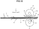
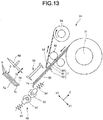
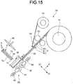
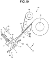
- FIG. 10 to Fig. 19 An example of the operation of the sheet binding device 1 is shown in Fig. 10 to Fig. 19.
- Fig. 10 to Fig. 19 are front views exemplifying the operation of the sheet binding device 1.
- the sheet binding device 1 stops the sheet S conveyed to the main guide 31 by moving the stopper 33 to the regulation position.
- the plurality of the sheets S is overlapped in order to form the sheet bundle 5.
- the sheet binding device 1 moves the stopper 33 to the releasing position.
- the sheet binding device 1 switches the switching member 34 towards the second conveyance direction.
- the sheet binding device 1 moves the second roller 42 towards the first roller 41.
- the sheet bundle 5 and the outer peripheral surface 42s of the second roller 42 are deformed into the arc shape along the outer peripheral surface 41s of the first roller 41.
- the sheet binding device 1 of the present embodiment determines a controlled variable of the sheet shift section 23 based on at least one of the information relating to the plurality of the sheets S, the information relating to the tape T and the information relating to the binding method of the sheet bundle 5 by the tape T. For example, the sheet binding device 1 determines the rotation angle of the first roller 41 as the controlled variable of the sheet shift section 23. As shown in Fig. 6 , the sheet binding device 1 forward rotates the first roller 41 based on the determined rotation angle of the first roller 41 in a state in which the sheet bundle 5 is sandwiched between the first roller 41 and the second roller 42.
- the second roller 42 rotates along with the rotation of the first roller 41 while maintaining the state of being recessed along the outer peripheral surface 41s of the first roller 41.
- a state is formed in which the plurality of the sheets S is shifted stepwise in the sheet conveyance direction X1 at the edge 5a of the sheet bundle 5.
- the "edge 5a of the sheet bundle 5" in the following description refers to the edge 5a of the sheet bundle 5 in which the plurality of the sheets S is shifted stepwise.
- the sheet binding device 1 moves the second roller 42 in a direction away from the first roller 41.
- the recess of the outer peripheral surface 42s of the second roller 42 is released.
- the sheet binding device 1 reversely rotates the first roller 41 and the second roller 42 to move the sheet bundle 5 in a reverse direction X2 to the sheet conveyance direction X1.
- the sheet binding device 1 switches the switching member 34 to switch the conveyance path from the second conveyance direction to the first conveyance direction.
- the sheet binding device 1 forward rotates the first roller 41 and the second roller 42 to move the sheet bundle 5 towards the tape attaching section 59.
- the sheet binding device 1 of the present embodiment changes the length L of the tape T cut by the cutter 56 based on the shift amount d between the sheets S changed by the controller 26.
- the controller 26 controls the drive source 73 of the cutting length change section 57 to change the position of the cutter 56.
- the sheet binding device 1 enables the tape holding section 58 to abut against the tape T to support the tape T in a state of maintaining the attitude of the tape T.
- the sheet binding device 1 moves the tape holding section 58 between the sheet bundle 5 and the tape attaching section 59.
- the tape holding section 58 arranges the tape T over the first roller 91 and the second roller 92.
- the sheet binding device 1 cuts the belt-like tape T by the cutter 56 to form the sheet-like tape T.
- the tape T is cut into a necessary length.
- the sheet binding device 1 forward rotates the first roller 41 and the second roller 42 to move the sheet bundle 5 towards the tape attaching section 59.
- the sheet binding device 1 enables the front end of the edge 5a of the sheet bundle 5 to collide against the tape T.
- the sheet binding device 1 inserts the edge 5a of the sheet bundle 5 and the tape T between the first roller 91 and the second roller 92.
- the edge 5a of the sheet bundle 5 and the tape T are inserted between the first roller 91 and the second roller 92, the first roller 91 and the second roller 92 move along an outer shape of the edge 5a of the sheet bundle 5.
- the first roller 91 and the second roller 92 press the tape T towards the edge 5a of the sheet bundle 5.
- the tape T follows the stepwise part of the sheet bundle 5 in order and closely adheres thereto.
- the edge 5a of the sheet bundle 5 has the first surface 7a, the second surface 7b and an end surface 7c.
- the first surface 7a and the second surface 7b are arranged along the sheet conveyance direction X1.
- the second surface 7b is positioned at an opposite side to the first surface 7a.
- the end surface 7c is positioned between the first surface 7a and the second surface 7b and the plurality of the sheets S are stepwise shifted.
- the sheet S is attached over the first surface 7a, the end surface 7c and the second surface 7b at the edge 5a of the sheet bundle 5.
- all sheets including the middle page of the sheet bundle 5 are integrated by the tape T.
- a processing for attaching the tape T to the edge 5a of the sheet bundle 5 is completed.
- the sheet binding device 1 reversely rotates the first roller 41 and the second roller 42 to pick out the sheet bundle 5 between the first roller 91 and the second roller 92.
- the sheet binding device 1 further reversely rotates the first roller 41 and the second roller 42 to discharge the sheet bundle 5 to a discharge section of the sheet binding device 1.
- the shift amount d between the sheets S is increased, the adhesive area between the sheet S and the tape T is increased, and the holding force of the sheet S can be increased.
- the shift amount d between the sheets S is increased, the appearance as the sheet bundle 5 may be reduced in some cases.
- the controller 26 of the sheet binding device 1 of the present embodiment changes the shift amount between the sheets S in the plurality of the sheets S shifted by the sheet shift section 23 based on the information acquired by the interface 21.
- the controller 26 controls the sheet shift section 23 in such a way as to decrease the shift amount d between the sheets S in a case in which the thickness of the sheet S is thicker than the preset reference value.
- the sheet binding device 1 ensures the holding force with respect to the sheet S, and the appearance of the sheet bundle 5 can be improved.
- the controller 26 controls the sheet shift section 23 in such a way as to decrease the shift amount d between the sheets S in a case in which the coefficient of friction of the sheet S is greater than the preset reference value.
- the sheet binding device 1 can ensure the holding force with respect to the sheet S and can also improve the appearance of the sheet bundle 5.
- the sheet binding device 1 can ensure the holding force with respect to the sheet S and can also improve the appearance of the sheet bundle 5.
- the controller 26 changes the shift amount d between the sheets S by the sheet shift section 23 based on the information relating to the alignment state of the plurality of the sheets S before the plurality of the sheets S is shifted by the sheet shift section 23.
- the sheet binding device 1 can ensure the holding force with respect to the sheet S and can also improve the appearance of the sheet bundle 5.
- the controller 26 controls the sheet shift section 23 in such a way as to decrease the shift amount d between the sheets S in a case in which the adhesion of the tape T is greater than the preset reference value.
- the sheet binding device 1 can ensure the holding force with respect to the sheet S and can also improve the appearance of the sheet bundle 5.
- the controller 26 controls the sheet shift section 23 in such a way as to decrease the shift amount d between the sheets S in a case in which the elasticity of the tape T is greater than the preset reference value and in a case in which the thickness of the tape T is thinner than the preset reference value.
- the sheet binding device 1 can ensure the holding force with respect to the sheet S and can also improve the appearance of the sheet bundle 5.
- the sheet bundle 5 is easy to stabilize. As a result, it is possible to ensure the holding force to the sheet S by small contact area.
- the controller 26 controls the sheet shift section 23 in such a way as to decrease the shift amount d between the sheets S in a case in which the tape T is attached to the predetermined position of the edge 5a of the sheet bundle 5.
- the sheet binding device 1 can ensure the holding force with respect to the sheet S and can also improve the appearance of the sheet bundle 5.
- the controller 26 controls the sheet shift section 23 in such a way as to decrease the shift amount d between the sheets S in a case in which the attachment number of the tapes T is greater than the preset reference number.
- the sheet binding device 1 can ensure the holding force with respect to the sheet S and can also improve the appearance of the sheet bundle 5.
- the length A of the tape T along the edge 5a of the sheet bundle 5 is relatively long, as the adhesive area between the sheet S and the tape T is increased, it is possible to increase the holding force to the sheet S.
- the controller 26 controls the sheet shift section 23 in such a way as to decrease the shift amount d between the sheets S in a case in which the length A of the tape T along the edge 5a of the sheet bundle 5 is longer than the preset reference length.
- the sheet binding device 1 can ensure the holding force with respect to the sheet S and can also improve the appearance of the sheet bundle 5.
- the controller 26 of the present embodiment controls the sheet shift section 23 in such a way as to decrease the shift amount d between the sheets S in a case in which the "temporary fastening (weak adhesion mode)" is selected. Thus, the contact area between the sheet S and the tape T is decreased, and the binding strength of the sheet bundle 5 by the tape T can be decreased.
- the controller 26 controls the sheet shift section 23 in such a way as to increase the shift amount d between the sheets S in a case in which the "binding (strong adhesion mode)" is selected as the binding strength of the sheet bundle 5 by the tape T.
- the contact area between the sheet S and the tape T is increased and the binding strength of the sheet bundle 5 by the tape T can be increased. It is possible to bind the sheet bundle 5 with a desired binding strength in response to a use purpose of the sheet bundle 5.
- the cutting length change section 57 of the sheet binding device 1 of the present embodiment changes the length L of the tape T cut by the cutter 56 based on the shift amount d of the plurality of the sheets S changed by the controller 26.
- the length L of the tape T can be changed according to the shift amount d between the sheets S.
- the sheet binding device 1 may be a device independently used regardless of the image forming apparatus 2.
- the sheet binding device 1 may include an operation reception section 101 (refer to Fig. 1 and Fig. 2 ) instead of the interface 21.
- the operation reception section 101 has a touch panel or a switch to receive the operation by the user relating to the plurality of the sheets S, the tape T and the binding method of the sheet bundle 5 by the tape T.
- the operation reception section 101 has a substantially same constitution and function as the control panel 11 of the image forming apparatus 2.
- the sheet binding device 1 may include a detection section 102 arranged in the conveyance path of the sheet S to count the number of the sheets S.
- the detection section 102 counts the number of the sheets S to acquire the information relating to the binding number of the sheets S.
- the operation reception section 101 and the detection section 102 are cooperated to form an example of the "information acquisition section". Furthermore, at least one of the operation reception section 101 and the detection section 102 may be omitted.
- first roller 41 is actively rotated, and the second roller 42 is driven to rotate in the sheet shift section 23 is described; however, the present invention is not limited to this example.
- both the first roller 41 and the second roller 42 may rotate independently.
- the sheet shift section 23 is not limited to including the first roller 41 and the second roller 42.
- the sheet shift section 23 may include a belt mechanism 110 instead of the second roller 42.
- the belt mechanism 110 is an example of the "second abutting member".
- the belt mechanism 110 includes a belt 111, a first pulley 112 and a second pulley 113.
- the belt 111 is wrapped around the first pulley 112 and the second pulley 113. If the belt mechanism 110 is moved towards the first roller 41, the sheet bundle 5 and an outer circumferential surface 111s of the belt 111 are deformed into an arc shape along the outer peripheral surface 41s of the first roller 41. In this state, by rotating the first roller 41 in the forward direction, as in the above embodiment, the plurality of sheets S is shifted stepwise at the edge 5a of the sheet bundle 5.
- the sheet shift section 23 may include the first roller 41 and a second roller 121 smaller than the first roller 41.
- the second roller 121 is an example of the "second abutting member".
- the second roller 121 moves along the outer peripheral surface 41s of the first roller 41 in a state in which the sheet bundle 5 is sandwiched between the first roller 41 and the second roller 121.
- the plurality of the sheets S is stepwise shifted at the edge 5a of the sheet bundle 5.
- the controller 26 changes a feeding position (in other words, a length Q of the sheet S curved along the outer peripheral surface 41s of the first roller 41) of the sheet S to the upper end of the first roller 41 to change the shift amount d between the sheets S in the plurality of the sheets S.
- the cutting length change section 57 may change an extension length of the tape T with respect to the cutter 56 fixed at the fixed position instead of moving of the position the cutter 56 to change a cutting position of the tape T by the cutter 56.
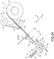
- Fig. 24 is a diagram illustrating the sheet binding device 1 in a case in which the number of the sheets S forming the sheet bundle 5 is relatively large.
- the cutting length change section 57 has a drive source 132 (for example, motor) for rotating a web roll 131 housed in the unwinding section 51.
- the cutting length change section 57 increases the extension length (length of a part extending beyond the cutter 56 if viewed from the unwinding section 51) of the tape T with respect to the cutter 56 by increasing the drive amount of the drive source 132 to be larger than the reference amount.
- the cutting length change section 57 increases the length L of the tape T cut by the cutter 56.
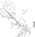
- Fig. 25 is a diagram illustrating the sheet binding device 1 in a case in which the number of the sheets S forming the sheet bundle 5 is relatively small.
- the cutting length change section 57 decreases the extension length of the tape T with respect to the cutter 56 by decreasing the drive amount of the drive source 132 to be smaller than the reference amount.
- the cutting length change section 57 reduces the length L of the tape T cut by the cutter 56.
- the sheet binding device has the controller for changing the shift amount between sheets in a plurality of sheets shifted by the sheet shift section based on the information acquired by the information acquisition section.
- the sheet binding device capable of changing a form of the binding part of the sheet bundle.
Landscapes
- Engineering & Computer Science (AREA)
- Physics & Mathematics (AREA)
- General Physics & Mathematics (AREA)
- Textile Engineering (AREA)
- Mechanical Engineering (AREA)
- Folding Of Thin Sheet-Like Materials, Special Discharging Devices, And Others (AREA)
Abstract
Description
- The present invention relates to the field of a sheet binding technology, e.g. by a stapler, in general, and embodiments described herein relate particularly to a sheet binding device, an image forming apparatus and a method for binding sheets.
- There is known a sheet binding device for binding an edge of sheets in a bundle with a stapler and the like.
- However, there are instances when it is preferable that the sheet binding device changes a form of a binding part of the sheet bundle.
- To this end, there is provided a sheet binding device, comprising:
- a sheet shift section configured to shift a plurality of sheets forming a sheet bundle from each other at an edge of the sheet bundle;
- a tape attaching section configured to attach a tape to the edge of the sheet bundle;
- an information acquisition section configured to acquire information relating to at least one of the plurality of the sheets, the tape, and a binding method of the sheet bundle by the tape; and
- a controller configured to change a shift amount between sheets in the plurality of the sheets that is shifted by the sheet shift section based on the information acquired by the information acquisition section.
- Preferably, the information acquisition section is further configured to acquire information relating to at least one of a thickness of the sheet, a type of the sheet, and a binding number of sheets as information relating to a plurality of sheets, and
the controller is further configured to change the shift amount of the plurality of sheets shifted by the sheet shift section based on the information relating to at least one of the thickness of the sheet, the type of the sheet, and the binding number of the sheets acquired by the information acquisition section. - Preferably still, the information acquisition section is further configured to acquire information relating to an alignment state of a plurality of sheets before the plurality of sheets is shifted by the sheet shift section as the information relating to the plurality of sheets, and
the controller is further configured to change the shift amount of the plurality of sheets shifted by the sheet shift section based on the information relating to the alignment state of the plurality of sheets acquired by the information acquisition section. - Preferably yet, the information acquisition section is further configured to acquire information relating to the type of the tape as the information relating to the tape, and
the controller is further configured to change the shift amount of the plurality of sheets shifted by the sheet shift section based on the information relating to the type of the tape acquired by the information acquisition section. - Suitably, the information acquisition section is further configured to acquire information relating to at least one of an attachment position of the tape, an attachment number of tapes, and a length of the tape along the edge of the sheet bundle as information relating to the binding method of the sheet bundle by the tape, and
the controller is further configured to change the shift amount of the plurality of sheets shifted by the sheet shift section based on the information relating to at least one of the attachment position of the tape, the attachment number of tapes, and the length of the tape along the edge of the sheet bundle. - Suitably still, the information acquisition section is further configured to acquire information relating to a binding strength of the sheet bundle by the tape as the information relating to the binding method of the sheet bundle by the tape, and
the controller is further configured to change the shift amount of the plurality of sheets shifted by the sheet shift section based on the information relating to the binding strength of the sheet bundle by the tape acquired by the information acquisition section. - In the above device, the binding strength of the sheet bundle is preferably strong adhesion or temporary weak adhesion.
- Suitably yet, the information acquisition section is further configured to acquire the information relating to at least one of the plurality of sheets, the tape, and the binding method of the sheet bundle by the tape by receiving them from an external device.
- Typically, the information acquisition section comprises an operation reception section configured for receiving an operation by a user relating to at least one of the plurality of sheets, the tape, and the binding method of the sheet bundle by the tape.
- Typically still, the sheet binding device further comprises:
- a cutter configured to cut the tape supplied from a tape supply section, and
- a cutting length change section configured to change a length of the tape cut by the cutter based on the shift amount of the plurality of sheets changed by the controller.
- The invention also relates to an image forming apparatus, comprising:
- the sheet binding device as defined above , and an image forming section.
- Preferably, the image forming apparatus further comprises:
- an interface coupled to both the sheet binding device and the image forming section.
- The invention further relates to a sheet binding method, comprising:
- shifting a plurality of sheets forming a sheet bundle from each other at an edge of the sheet bundle;
- attaching a tape to the edge of the sheet bundle;
- acquiring information relating to at least one of the plurality of the sheets, the tape, and a binding method of the sheet bundle by the tape; and
- changing a shift amount between sheets in the plurality of the sheets that is shifted based on the information acquired.
- Preferably, the sheet binding method further comprises:
- acquiring information relating to at least one of a thickness of the sheet, a type of the sheet, and a binding number of sheets as information relating to a plurality of sheets, and
- changing the shift amount of the plurality of sheets shifted based on the information relating to at least one of the thickness of the sheet, the type of the sheet, and the binding number of the sheets.
- Preferably still, the sheet binding method further comprises:
- acquiring information relating to an alignment state of a plurality of sheets before the plurality of sheets is shifted as the information relating to the plurality of sheets, and
- changing the shift amount of the plurality of sheets shifted based on the information relating to the alignment state of the plurality of sheets.
- Preferably yet, the sheet binding method further comprises:
- acquiring information relating to the type of the tape as the information relating to the tape, and
- changing the shift amount of the plurality of sheets shifted based on the information relating to the type of the tape.
- In the above method, it preferably further comprises:
- acquiring information relating to at least one of an attachment position of the tape, an attachment number of tapes, and a length of the tape along the edge of the sheet bundle as information relating to the binding method of the sheet bundle by the tape, and
- changing the shift amount of the plurality of sheets shifted based on the information relating to at least one of the attachment position of the tape, the attachment number of tapes, and the length of the tape along the edge of the sheet bundle.
- In the above method further, it preferably, further comprises:
- acquiring information relating to a binding strength of the sheet bundle by the tape as the information relating to the binding method of the sheet bundle by the tape, and
- changing the shift amount of the plurality of sheets shifted based on the information relating to the binding strength of the sheet bundle by the tape.
- The above and other objects, features and advantages of the present invention will be made apparent from the following description of the preferred embodiments, given as non-limiting examples, with reference to the accompanying drawings, in which:
-
Fig. 1 is a front view illustrating a sheet binding device according to an embodiment; -
Fig. 2 is a block diagram illustrating the system constitution of the sheet binding device according to the embodiment; -
Fig. 3 is a front view illustrating the internal constitution of the sheet binding device according to the embodiment; -
Fig. 4 is a side view illustrating a state in which a plurality of sheets is shifted at an edge of a sheet bundle according to the embodiment; -
Fig. 5 is a front view illustrating the operation of a sheet shift section; -
Fig. 6 is a front view illustrating the operation of the sheet shift section followingFig. 5 ; -
Fig. 7 is a front view illustrating the principle in which a plurality of sheets is shifted according to the embodiment; -
Fig. 8 is a side view illustrating a shift amount between sheets in a plurality of sheets according to the embodiment; -
Fig. 9 is a side view illustrating the operation of changing the shift amount between sheets according to the embodiment; -
Fig. 10 is a front view illustrating the operation of the sheet binding device followingFig. 6 ; -
Fig. 11 is a front view illustrating the operation of the sheet binding device followingFig. 10 ; -
Fig. 12 is a front view illustrating the operation of the sheet binding device followingFig. 11 ; -
Fig. 13 is a front view illustrating the operation of the sheet binding device followingFig. 12 ; -
Fig. 14 is a front view illustrating the operation of the sheet binding device followingFig. 13 ; -
Fig. 15 is a front view illustrating the operation of the sheet binding device followingFig. 14 ; -
Fig. 16 is a front view illustrating the operation of the sheet binding device followingFig. 15 ; -
Fig. 17 is a front view illustrating the operation of the sheet binding device followingFig. 16 ; -
Fig. 18 is a front view illustrating the operation of the sheet binding device followingFig. 17 ; -
Fig. 19 is a front view illustrating the operation of the sheet binding device followingFig. 18 ; -
Fig. 20 is a side view illustrating an alignment state of the plurality of sheets according to the embodiment; -
Fig. 21 is a plan view illustrating a relationship between a tape and the sheet bundle according to the embodiment; -
Fig. 22 is a front view illustrating a first modification of the sheet shift section according to the embodiment; -
Fig. 23 is a front view illustrating a second modification of the sheet shift section according to the embodiment; -
Fig. 24 is a front view illustrating a case in which the number of sheets forming a sheet bundle is relatively large, which is a modification of the sheet binding device according to the embodiment; and -
Fig. 25 is a front view illustrating a case in which the number of sheets forming a sheet bundle is relatively small, which is a modification of the sheet binding device according to the embodiment. - In accordance with an embodiment, a sheet binding device comprises a sheet shift section, a tape attaching section, an information acquisition section and a controller. The sheet shift section shifts a plurality of sheets forming a sheet bundle from each other at an edge of the sheet bundle. The tape attaching section attaches a tape to the edge of the sheet bundle. The information acquisition section acquires information relating to at least one of the plurality of the sheets, the tape, and a binding method of the sheet bundle by the tape. The controller changes a shift amount between sheets in the plurality of the sheets that is shifted by the sheet shift section based on the information acquired by the information acquisition section.
- Hereinafter, a sheet binding device of an embodiment is described with reference to the accompanying drawings. Further, in the following description, the components with the same or similar functions are donated with the same reference numerals. The overlapping description those of may be omitted in some cases. In the present application, a sheet-like medium containing a paper and the like is referred to as a "sheet".
- First, one embodiment is described with reference to
Fig. 1 to Fig. 21 . -
Fig. 1 is a front view illustrating a sheet binding device (sheet processing apparatus) 1 according to the present embodiment.Fig. 2 is a block diagram illustrating the system constitution of thesheet binding device 1 according to the present embodiment. The sheetbinding device 1 of the present embodiment is a binding device for binding anedge 5a of asheet bundle 5 with a tape T (refer toFig. 18 ). For example, thesheet binding device 1 is a post-processing device installed adjacent to animage forming apparatus 2 to carry out a post-processing to a sheet S conveyed from theimage forming apparatus 2. Further, thesheet binding device 1 is not limited to the above example, and may be, for example, a device that is placed on a desktop or floor to be used alone. - Herein, first, the
image forming apparatus 2 is simply described. - As shown in
Fig. 1 andFig. 2 , theimage forming apparatus 2 includes aninterface 10, acontrol panel 11, ascanner section 12, aprinter section 13, asheet feed section 14, asheet discharge section 15 and acontroller 16. - The
interface 10 is connected with aninterface 21 of thesheet binding device 1 in a wired or wireless manner. - The
control panel 11 includes various keys to receive an operation by a user. For example, in a case in which a plurality of the sheets S discharged from theimage forming apparatus 2 is bound by thesheet binding device 1, thecontrol panel 11 receives an operation by the user relating to at least one of the plurality of the sheets S, the tape T and a binding method of thesheet bundle 5 by the tape T. - For example, the
control panel 11 receives an operation of selecting a thickness of the sheet S and an operation of selecting a type of the sheet S as the operation by the user relating to the plurality of the sheets S. The "type of the sheet S" in the present application includes types classified according to a material of the sheet S, a surface processing of the sheet S and the like. - For example, the
control panel 11 receives an operation of selecting the type of the tape T as the operation by the user relating to the tape T. The "type of the tape T" in the present application includes types classified according to at least one of an adhesion of the tape T, a thickness of the tape T and an elasticity of the tape T. The information relating to the type of the tape T may be acquired by a tapeinformation acquisition section 51a (refer toFig. 3 ) provided in thesheet binding device 1 as described later. - For example, the
control panel 11 receives an operation of selecting an attachment position of the tape T to thesheet bundle 5, an operation of selecting an attachment number of the tapes T to thesheet bundle 5 and an operation of selecting a length A of the tape T (refer toFig. 21 ) along theedge 5a of thesheet bundle 5 as the operations by the user relating to the binding method of thesheet bundle 5 by the tape T. The operation of selecting the attachment position of the tape T to thesheet bundle 5 refers to an operation of selecting which position of theedge 5a of thesheet bundle 5 is bound by the tape T. The operation of selecting the attachment number of the tapes T to thesheet bundle 5 is an operation of selecting how many positions of thesheet bundle 5 are bound by the tape T. The operation of selecting the length A of the tape T along theedge 5a of thesheet bundle 5 refers to an operation of selecting the length A of the tape T in a case in which a plurality of lengths can be selected as the length A of the tape T. - For example, the
control panel 11 receives an operation of selecting a binding strength of thesheet bundle 5 by the tape T as the operation by the user relating to the binding method of thesheet bundle 5 by the tape T. The operation of selecting the binding strength of thesheet bundle 5 by the tape T is an operation of selecting strength of a binding state the user desires. For example, the operation of selecting the binding strength of thesheet bundle 5 by the tape T is an operation of selecting the binding state of thesheet bundle 5 by the tape T between a "binding (strong adhesion mode)" and a "temporary fastening (weak adhesion mode)". The "binding" is, for example, a strength at which thesheet bundle 5 is relatively firmly bound with the tape T similar to a case of binding thesheet bundle 5 with a stapler. On the other hand, the "temporary fastening" has weaker binding strength than the "binding". The "temporary fastening" is, for example, a strength at which thesheet bundle 5 is relatively loosely bound with the tape T to make thesheet bundle 5 easy to disassemble. - For example, the
control panel 11 may have a first button B1 corresponding to the "binding" and a second button B2 corresponding to the "temporary fastening" as selection buttons displayed on a touch display. For example, the first button B1 corresponding to the "binding" may contain a mark or an image of the stapler. The second button B2 corresponding to the "temporary fastening" may include a mark or an image of a clip. - The
image forming apparatus 2 sends information relating to at least one of the plurality of the sheets S, the tape T and the binding method of thesheet bundle 5 by the tape T input via the operation on thecontrol panel 11 to thesheet binding device 1 via theinterface 10 as a part of a command. - The
scanner section 12 reads image information of a copied object. Theprinter section 13 forms an image on the sheet S based on image information received from thescanner section 12 or an external device. Thesheet feed section 14 supplies the sheet S to theprinter section 13. Thesheet discharge section 15 coveys the sheet S discharged from theprinter section 13 to thesheet binding device 1. - The
controller 16 controls various operations of theinterface 10, thecontrol panel 11, thescanner section 12, theprinter section 13, thesheet feed section 14 and thesheet discharge section 15. For example, thecontroller 16 acquires information relating to a binding number of the sheets S (in other words, the number of sheets S bound as one sheet bundle 5) from a sensor provided in theimage forming apparatus 2 or an external device. Theimage forming apparatus 2 sends the information relating to the binding number of the sheets S to thesheet binding device 1 through theinterface 10 as a part of the command. - The sheet
binding device 1 is described. - As shown in
Fig. 2 , thesheet binding device 1 includes theinterface 21, abundle creation section 22, asheet shift section 23, atape processing section 24, astorage section 25 and acontroller 26. - The
interface 21 is an example of an "information acquisition section". For example, theinterface 21 acquires the information relating to at least one of the plurality of the sheets S, the tape T and the binding method of thesheet bundle 5 by the tape T by receiving them from theimage forming apparatus 2 as the part of the command. Theimage forming apparatus 2 is an example of an "external device". Theinterface 21 sends the acquired various information to thecontroller 26. - For example, the
interface 21 acquires the information relating to the thickness of the sheet S, the type of the sheet S and the binding number of the sheets S as the information relating to the plurality of the sheets S. The "information relating to the thickness of the sheet S" indicates, for example, a thickness of one sheet S forming thesheet bundle 5. The "information relating to type of the sheet S" indicates, for example, the type of the sheet S forming thesheet bundle 5. The "information relating to the binding number of the sheets S" indicates, for example, the number of the sheets S forming onesheet bundle 5. - For example, the
interface 21 may acquire information relating to an alignment state of the plurality of the sheets S before the plurality of the sheets S is shifted by thesheet shift section 23 as the information relating to the plurality of the sheets S. The alignment state of the plurality of the sheets S before the plurality of the sheets S is shifted by thesheet shift section 23 depends on the type of the sheet S in some cases. Thus, the "information indicating the type of the sheet S" is an example of the "information relating to the alignment state of the plurality of the sheets S before the plurality of the sheets S is shifted by thesheet shift section 23". The "information relating to the alignment state of the plurality of the sheets S before the plurality of the sheets S is shifted by thesheet shift section 23" may be acquired by detecting an actual state of thesheet bundle 5 by a sensor IS (refer toFig. 20 ) arranged in thesheet binding device 1. In this case, the sensor IS is an example of an "information acquisition section". - For example, the
interface 21 acquires the information relating to the type of the tape T as the information relating to the tape T. The "information relating to the type of the tape T" indicates, for example, the type of the tape T attached to thesheet bundle 5. - For example, the
interface 21 acquires the information relating to the attachment position of the tape T to thesheet bundle 5, the attachment number of the tapes T to thesheet bundle 5 and the length A of the tape T along theedge 5a of thesheet bundle 5 as the information relating to the binding method of thesheet bundle 5 by the tape T. The "information relating to the attachment position of the tape T" indicates, for example, which position of theedge 5a of thesheet bundle 5 is bound by the tape T. The "information relating to the attachment number of the tapes T" indicates, for example, how many positions of thesheet bundle 5 is bound by the tape T. The "information relating to the length A of the tape T along theedge 5a of thesheet bundle 5" indicates the length A of the tape T along theedge 5a of thesheet bundle 5. - For example, the
interface 21 further acquires the information relating to the binding strength of thesheet bundle 5 by the tape T as the information relating to the binding method of thesheet bundle 5 by the tape T. The "information relating to the binding strength of thesheet bundle 5 by the tape T" indicates, for example, a strength of the binding state the user desires. The "information relating to the binding strength of thesheet bundle 5 by the tape T" indicates, for example, whether the binding state of thesheet bundle 5 by the tape T is the "binding (strong adhesion mode)" described above or the "temporary fastening (weak adhesion mode)" described above. - The
bundle creation section 22 is described. -
Fig. 3 is a front view illustrating the internal constitution of thesheet binding device 1. - As shown in
Fig. 3 , thebundle creation section 22 creates thesheet bundle 5 by overlaying the plurality of the sheets S. Thebundle creation section 22 includes amain guide 31, asub guide 32, astopper 33 and a switchingmember 34. - The
main guide 31 guides the sheet S along a sheet conveyance direction X1. The plurality of the sheets S is stacked on themain guide 31 in order to form thesheet bundle 5. A downstream side end of themain guide 31 in the sheet conveyance direction X1 is formed into a comb-tooth shape so as to avoid afirst roller 41 of thesheet shift section 23. - The
sub guide 32 faces themain guide 31 in a thickness direction Z of the sheet bundle 5 (hereinafter, referred to as a sheet bundle thickness direction Z). A space where the sheets S are stacked is arranged between themain guide 31 and thesub guide 32. The downstream side end of thesub guide 32 in the sheet conveyance direction X1 is formed into a comb-tooth shape so as to avoid asecond roller 42 of thesheet shift section 23. - The
stopper 33 is arranged at the downstream side end of themain guide 31 in the sheet conveyance direction X1. Thestopper 33 can be moved between a regulation position (shown by a solid line inFig. 3 ) and a releasing position (shown by a two-dot chain line inFig. 3 ) by a movement mechanism (not shown). At the regulation position, thestopper 33 protrudes upward with respect to the upper surface of themain guide 31. At the regulation position, thestopper 33 stops the sheet S by abutting against an end of the sheet S. Thus, the sheet S is collected on themain guide 31 to form thesheet bundle 5. On the other hand, at the releasing position, thestopper 33 is retracted downward with respect to the upper surface of themain guide 31. At the releasing position, thestopper 33 passes thesheet bundle 5 on themain guide 31 towards the switchingmember 34. - The switching
member 34 switches a conveyance path of thesheet bundle 5. Hereinafter, a direction in which thesheet bundle 5 is conveyed towards the tape processing section 24 (specifically, atape attaching section 59 described later) is referred to as a "first conveyance direction". On the other hand, a direction in which thesheet bundle 5 is conveyed to a position different from the tape attaching section 59 (for example, below the bundle creation section 22) is referred to as a "second conveyance direction". The switchingmember 34 switches the conveyance path of thesheet bundle 5 between the first conveyance direction and the second conveyance direction. - The
sheet shift section 23 is described. - The
sheet shift section 23 shifts the plurality of the sheets S little by little in order in the sheet conveyance direction X1 to form a state in which the plurality of the sheets S forming thesheet bundle 5 is shifted from each other at theedge 5a of thesheet bundle 5. For example, thesheet shift section 23 form a state in which the plurality of the sheets S is shifted stepwise at theedge 5a of thesheet bundle 5. -
Fig. 4 is a side view illustrating a state in which the plurality of sheets S is shifted at theedge 5a of thesheet bundle 5. - As shown in
Fig. 4 , in the present application the "state in which the plurality of the sheets S forming thesheet bundle 5 is shifted from each other at theedge 5a" refers to a state in which the plurality of the sheets S is mutually shifted and overlapped. In other words, the above state is a state in which the edges of the plurality of the sheets S that is overlapped are shifted from each other and the edges of the sheets S forming thesheet bundle 5 have a step difference. Further, in other words, the above state is a state in which a part of the plurality of the sheets is overlapped in a layer shape. The "state in which the plurality of the sheets S forming thesheet bundle 5 is shifted stepwise at theedge 5a" in the present application refers to, for example, a state in which projecting amount of each sheet S in the sheet conveyance direction X1 is gradually increased (gradually decreased) in the order in which the plurality of the sheets S is overlapped. Further, the above state is not limited to a state in which the plurality of the sheets S is substantially evenly shifted from each other (refer toFig. 4 (a) ), and may be state in which the plurality of the sheets S is unevenly shifted from each other (refer toFig. 4 (b) ). - In order to form those states, as shown in
Fig. 3 , thesheet shift section 23 of the present embodiment has thefirst roller 41 and asecond roller 42. Thefirst roller 41 is an example of a "first abutting member". Thesecond roller 42 is an example of a "second abutting member". - The
first roller 41 is mounted in afirst shift 43. Thefirst roller 41 is a driving roller driven by a motor (not shown) via thefirst shift 43. Thefirst roller 41 is fixed at a fixed position. The material of thefirst roller 41 is not particularly limited. For example, thefirst roller 41 is formed by EPDM (ethylene propylene diene rubber). - The
second roller 42 is mounted in asecond shift 44. For example, thesecond roller 42 is a driven roller rotating according to the rotation of thefirst roller 41. Thesecond roller 42 can be moved by a movement mechanism (not shown) in a direction close to thefirst roller 41 or a direction away from thefirst roller 41. Thesecond roller 42 is moved towards thefirst roller 41 to contact with thesheet bundle 5 from an opposite side to thefirst roller 41. - Herein, an outer
peripheral surface 42s of thesecond roller 42 is softer than an outerperipheral surface 41s of thefirst roller 41 and is deformable along the surface of the sheet bundle 5 (refer toFig. 5 ). For example, thesecond roller 42 is formed by a sponge or a rubber having a cavity therein. In a case in which thesecond roller 42 approaches thefirst roller 41, the outerperipheral surface 42s of thesecond roller 42 together with thesheet bundle 5 is deformed into an arc shape along the outerperipheral surface 41s of thefirst roller 41. - The procedures for enabling the plurality of the sheets S to be shifted from each other by the
sheet shift section 23 are described. -
Fig. 5 andFig. 6 are front views illustrating the operation of thesheet shift section 23. - As shown in
Fig. 5 , thesheet binding device 1 moves thesecond roller 42 towards thefirst roller 41. Thus, thesheet bundle 5 and the outerperipheral surface 42s of thesecond roller 42 are deformed into arc shapes along the outerperipheral surface 41s of thefirst roller 41. - As shown in
Fig. 6 , thesheet binding device 1 forward rotates thefirst roller 41 in a state of sandwiching thesheet bundle 5 between thefirst roller 41 and thesecond roller 42. Thus, thesecond roller 42 rotates along with the rotation of thefirst roller 41 while maintaining a state in which thesecond roller 42 is recessed along the outerperipheral surface 41s of thefirst roller 41. As a result, a state is formed in which the plurality of the sheets S is shifted stepwise in the sheet conveyance direction X1 at theedge 5a of thesheet bundle 5. -
Fig. 7 is a front view illustrating the principle in which the plurality of sheets S is shifted. - As shown in
Fig. 7 , if thesecond roller 42 is pressed to thefirst roller 41 via thesheet bundle 5, the outerperipheral surface 42s of thesecond roller 42 is deformed into an arc shape along the outerperipheral surface 41s of thefirst roller 41. Herein, a length (length of the arc) d1 in a circumferential direction of a part contacting with thesheet bundle 5 of the outerperipheral surface 41s of thefirst roller 41 is referred to as a "first length d1". On the other hand, a length d2 in a circumferential direction of thefirst roller 41 of a part (recessed part) contacting with thesheet bundle 5 of the outerperipheral surface 42s of thesecond roller 42 is referred to as a "second length d2". The second length d2 is longer than the first length d1. The sheetbinding device 1 rotates thefirst roller 41 and thesecond roller 42 in such a state to send out thesheet bundle 5 in the sheet conveyance direction X1. At this time, a movement distance of the outerperipheral surface 42s of thesecond roller 42 is longer than that of the outerperipheral surface 41s of thefirst roller 41. In other words, a feeding amount of thesheet bundle 5 in the sheet conveyance direction X1 increases as approaching thesecond roller 42. Thus, a state is formed in which the plurality of the sheets S is stepwise shifted at theedge 5a of thesheet bundle 5. -
Fig. 8 is a side view illustrating a shift amount d between the sheets S in the plurality of the sheets S.Fig. 8(a) illustrates a case in which the shift amount d between the sheets S is relatively small. On the other hand,Fig. 8(b) illustrates a case in which the shift amount d between the sheets S is relatively large. - As shown in
Fig. 8 , the shift amount d between the sheets S refers to the shift amount d in the sheet conveyance direction X1 of two sheets S which are adjacent to each other and overlapped in the thickness direction of the sheet S. - If the shift amount d between the sheets S is large, an adhesive area between the sheet S forming the
sheet bundle 5 and the tape T is increased. Thus, a holding force of the sheet S by the tape T is increased, and the binding strength of thesheet bundle 5 is increased. On the other hand, if the shift amount d between the sheets S is small, the adhesive area between the sheet S forming thesheet bundle 5 and the tape T is reduced. Thus, the holding force of the sheet S by the tape T is decreased, and the binding strength of thesheet bundle 5 is decreased. - If setting the shift amount d between the sheets S to "d", the thickness of the sheet S to "t", a rotation angle (rotation number) of the
first roller 41 to "n", the following expression (1) holds.
- The shift amount d between the sheets S is determined by the rotation angle of the
first roller 41 and the thickness of the sheet S. In other words, the shift amount d between the sheets S is increased as the rotation angle of thefirst roller 41 is increased. On the other hand, the shift amount d between the sheets S is decreased as the rotation angle of thefirst roller 41 is decreased. Thus, thesheet shift section 23 can change the shift amount d between the sheets S by changing the rotation angle of thefirst roller 41. -
Fig. 9 is a side view illustrating the operation of changing the shift amount between sheets by thesheet shift section 23.Fig. 9 (a) illustrates a case in which the shift amount d between the sheets S is relatively small. On the other hand,Fig. 9(b) illustrates a case in which the shift amount d between the sheets S is relatively large. - As shown in
Fig. 9 , thesheet shift section 23 can decrease the shift amount d between the sheets S by making the rotation angle of thefirst roller 41 smaller than a preset reference amount. On the other hand, thesheet shift section 23 can increase the shift amount d between the sheets S by making the rotation angle of thefirst roller 41 larger than the reference amount. - The control operation of the
controller 26 relating to thesheet shift section 23 is described first. - The
controller 26 of the present embodiment changes the shift amount d between the sheets S in the plurality of the sheets S shifted by thesheet shift section 23 based on the information acquired by theinterface 21. - Furthermore, the "information acquired by the information acquisition section" in the present application is not limited to the information directly acquired by the information acquisition section, and may also contain information obtained by executing operation and determination to the information directly acquired by the information acquisition section.
- For example, the
controller 26 of the present embodiment changes the shift amount d between the sheets S based on the information relating to at least one of the thickness of the sheet S, the type of the sheet S and the binding number of the sheets S acquired by theinterface 21. - For example, the
controller 26 controls thesheet shift section 23 in such a way as to decrease the shift amount d between the sheets S in a case in which the thickness of the sheet S is thicker than a preset reference value. On the other hand, thecontroller 26 controls thesheet shift section 23 in such a way as to increase the shift amount d between the sheets S in a case in which the thickness of the sheet S is thinner than the reference value or a reference value separately set. - For example, the
controller 26 controls thesheet shift section 23 in such a way as to decrease the shift amount d between the sheets S in a case in which a coefficient of friction of the surface of the sheet S is larger than a preset reference value. - On the other hand, the
controller 26 controls thesheet shift section 23 in such a way as to increase the shift amount d between the sheets S in a case in which the coefficient of friction of the surface of the sheet S is smaller than the reference value or a reference value separately set. Further, the information relating to the coefficient of friction of the surface of the sheet S is stored in thestorage section 25 in advance in association with the information relating to the type of the sheet S. Thecontroller 26 can acquire the information relating to the coefficient of friction of the surface of the sheet S by referring to thestorage section 25 based on the acquired information relating to the type of the sheet S. - For example, the
controller 26 controls thesheet shift section 23 in such a way as to decrease the shift amount d between the sheets S in a case in which the binding number of the sheets S is smaller than a preset reference number. On the other hand, thecontroller 26 controls thesheet shift section 23 in such a way as to increase the shift amount d between the sheets S in a case in which the binding number of the sheets S is greater than a preset reference number or a reference number separately set. - The
controller 26 of the present embodiment changes the shift amount d between the sheets S by thesheet shift section 23 based on the information relating to the alignment state of the plurality of the sheets S before the plurality of the sheets S is shifted by thesheet shift section 23. - For example, the
controller 26 increases the shift amount d between the sheets S by thesheet shift section 23 so as to protrude sequentially in the sheet conveyance direction X1 in the order in which the plurality of the sheets S is overlapped in a state in which the plurality of the sheets S is shifted by thesheet shift section 23 even if the front ends of the plurality of the sheets S are not aligned (refer toFig. 20 ). In other words, in a case in which the alignment state of the plurality of the sheets S is not good (front ends are not aligned), the rotation angle of thefirst roller 41 is increased than normal angle to increase the shift amount d. In this way, in a case in which there is a step difference in a reverse direction to a desired direction, the step difference is canceled. - The
controller 26 of the present embodiment changes the shift amount d between the sheets S based on the information relating to the type of the tape T acquired by theinterface 21. - For example, the
controller 26 controls thesheet shift section 23 in such a way as to decrease the shift amount d between the sheets S in a case in which the adhesion (adhesive force) of the tape T is greater than a preset reference value. On the other hand, thecontroller 26 controls thesheet shift section 23 in such a way as to increase the shift amount d between the sheets in a case in which the adhesion of the tape T is smaller than the reference value or a reference value separately set. Further, the information relating to the adhesion of the tape T is stored in thestorage section 25 in advance in association with the information relating to the type of the tape T. Thecontroller 26 can acquire the information relating to the adhesion of the tape T by referring to thestorage section 25 based on the acquired information relating to the type of the tape T. - For example, the
controller 26 controls thesheet shift section 23 in such a way as to decrease the shift amount d between the sheets S in a case in which the thickness of the tape T is thinner than a preset reference value. On the other hand, thecontroller 26 controls thesheet shift section 23 in such a way as to increase the shift amount d between the sheets S in a case in which the thickness of the tape T is thicker than the preset reference value or a reference value separately set. Further, the information relating to the thickness of the tape T is stored in thestorage section 25 in advance in association with the information relating to the type of the tape T. Thecontroller 26 can acquire the information relating to the thickness of the tape T by referring to thestorage section 25 based on the acquired information relating to the type of the tape T. - For example, the
controller 26 controls thesheet shift section 23 in such a way as to decrease the shift amount d between the sheets S in a case in which the elasticity of the tape T is greater than a preset reference value. On the other hand, thecontroller 26 controls thesheet shift section 23 in such a way as to increase the shift amount d between the sheets S in a case in which the elasticity of the tape T is smaller than the reference value or a reference value separately set. Further, the information relating to the elasticity of the tape T is stored in thestorage section 25 in advance in association with the information relating to the type of the tape T. Thecontroller 26 can acquire the information relating to the elasticity of the tape T by referring to thestorage section 25 based on the acquired information relating to the type of the tape T. - The
controller 26 of the present embodiment changes the shift amount d between the sheets S with thesheet shift section 23 based on information relating to at least one of the attachment position of the tape T to thesheet bundle 5, the attachment number of the tapes T to thesheet bundle 5 and the length A of the tape T along theedge 5a of thesheet bundle 5. - For example, the
controller 26 controls thesheet shift section 23 in such a way as to decrease the shift amount d between the sheets S in a case in which the tape T is attached at the substantially center of theedge 5a of thesheet bundle 5. On the other hand, thecontroller 26 controls thesheet shift section 23 in such a way as to increase the shift amount d between the sheets S in a case in which the tape T is attached only to a corner of thesheet bundle 5. - For example, the
controller 26 controls thesheet shift section 23 in such a way as to decrease the shift amount d between the sheets S in a case in which the attachment number of the tapes T to thesheet bundle 5 is greater than a preset reference number. On the other hand, thecontroller 26 controls thesheet shift section 23 in such a way as to increase the shift amount d between the sheets S in a case in which the attachment number of the tapes T to thesheet bundle 5 is smaller than the reference number or a reference number separately set. - For example, the
controller 26 controls thesheet shift section 23 in such a way as to decrease the shift amount d between the sheets S in a case in which the length A of the tape T along theedge 5a of thesheet bundle 5 is longer than a preset reference length. On the other hand, thecontroller 26 controls thesheet shift section 23 in such a way as to increase the shift amount d between the sheets S n a case in which the length A of the tape T along theedge 5a of thesheet bundle 5 is shorter than the reference length or a reference length separately set. - The
controller 26 of the present embodiment changes the shift amount d between the sheets S with thesheet shift section 23 based on the information relating to the binding strength of thesheet bundle 5 by the tape T. - For example, the
controller 26 controls thesheet shift section 23 in such a way as to decrease the shift amount d between the sheets S in a case in which the "temporary fastening (weak adhesion mode)" is selected as the binding strength of thesheet bundle 5 by the tape T. On the other hand, thecontroller 26 controls thesheet shift section 23 in such a way as to increase the shift amount d between the sheets Sin a case in which the "binding (strong adhesion mode)" is selected as the binding strength of thesheet bundle 5 by the tape T. - The
tape processing section 24 is described. - As shown in
Fig. 3 , thetape processing section 24 includes an unwindingsection 51, atape conveyance section 52, aseparation member 53, a windingsection 54, aguide base 55, acutter 56, a cuttinglength change section 57, atape holding section 58 and thetape attaching section 59. - The unwinding
section 51 is an example of a "tape supply section". For example, the unwindingsection 51 holds a web roll obtained by winding the belt-like tape T (hereinafter, simply referred to as the "tape T"). The unwindingsection 51 supplies the tape T in a length direction of the tape T. The tape T contains anadhesive layer 61, a protection film (first film) 62, and a peeling film (second film) 63 in a state of being held in the unwindingsection 51. Theprotection film 62 covers theadhesive layer 61 from one side. Theprotection film 62 is integral with theadhesive layer 61 at the time of using the tape T. On the other hand, the peelingfilm 63 covers theadhesive layer 61 from a side opposite to theprotection film 62. The peelingfilm 63 is peeled from theadhesive layer 61 before use of the tape T. The peelingfilm 63 is wound up by theseparation member 53 and the windingsection 54. - As shown in
Fig. 3 , for example, the tape T is mounted in the unwindingsection 51 in a state of being housed in the cartridge C. For example, the cartridge C has an identification section ID for identifying the type of the tape T. The identification section ID is an IC chip, a bar code, a block pattern and the like. Herein, thetape processing section 24 may include the tapeinformation acquisition section 51a. The tapeinformation acquisition section 51a is an example of the "information acquisition section". For example, the tapeinformation acquisition section 51a acquires the information relating to the type of the tape T by reading the information from the identification section ID of the cartridge C. The tapeinformation acquisition section 51a is a sensor or a microswitch. The tapeinformation acquisition section 51a sends the acquired information relating to the type of the tape T to thecontroller 26. Thecontroller 26 may control thesheet shift section 23 based on the information acquired by the tapeinformation acquisition section 51a. - The
tape conveyance section 52 conveys the tape T supplied from the unwindingsection 51 in the length direction of the tape T. For example, the length direction of the tape T is substantially parallel to the sheet bundle thickness direction Z. Theguide base 55 guides the tape T from which thepeeling film 63 is separated. Theguide base 55 supports the tape T at the time of holding the tape T and cutting the tape T. - The
cutter 56 cuts the belt-like tape T supplied from the unwindingsection 51 to form a sheet-like tape T. For example, thecutter 56 is a rotor cutter and includes acutting blade 56a and a supportingaxis 56b. Thecutting blade 56a is rotationally driven by rotation of the supportingaxis 56b by a motor (not shown). The constitution of thecutter 56 is not limited to the above example. The constitution of thecutter 56 may be any configuration as long as thecutter 56 can cut the tape T supplied from the unwindingsection 51. Thecutter 56 can be moved by a moving mechanism (not shown) in a direction close to the tape T or a direction away from the tape T. - The cutting
length change section 57 changes a length L (refer toFig. 16 ) of the tape T cut by thecutter 56. Further, "the length L of the tape" in the present application refers to a length (width) of the tape T in the sheet bundle thickness direction Z. In other words, the "length L of the tape" is a length in a direction from afirst surface 7a of thesheet bundle 5 towards asecond surface 7b in which theedge 5a of thesheet bundle 5 is packed. - The cutting
length change section 57 has amovement mechanism 71 for changing a relative position of thecutter 56 with respect to a front end Te of the tape T supplied from the unwindingsection 51. For example, themovement mechanism 71 changes the relative position of thecutter 56 with respect to the front end Te of the tape T by moving thecutter 56. For example, themovement mechanism 71 moves thecutter 56 in the sheet bundle thickness direction Z. The "relative position of thecutter 56 with respect to the front end Te of the tape T" is, for example, a relative position of thecutter 56 with respect to the front end Te of the tape T at the time the tape T is cut by thecutter 56. - In the present embodiment, the
movement mechanism 71 is provided with a supportingmember 72 supporting thecutter 56 and adrive source 73 for moving thecutter 56 via the supportingmember 72. For example, the supportingmember 72 is a ball screw connected to thecutter 56. Thedrive source 73 drives the ball screw to move thecutter 56. The constitutions of the supportingmember 72 and thedrive source 73 are not limited to the above examples. For example, the supportingmember 72 may be a cam abutting against thecutter 56. Thedrive source 73 may be a solenoid for moving thecutter 56 via the supportingmember 72. In this case, the supportingmember 72 is a connecting member for connecting thecutter 56 with the solenoid. - The constitution of the
movement mechanism 71 is not limited to the above example. For example, themovement mechanism 71 may change an extension length of the tape T with respect to thecutter 56 fixed at a fixed position to change the relative position ofcutter 56 with respect to the front end Te of the tape T. The constitution in this case is described later. - In the present embodiment, the cutting
length change section 57 is controlled by thecontroller 26 described later. For example, thecontroller 26 controls thedrive source 73 of the cuttinglength change section 57 to move thecutter 56 to change the length L of the tape T cut by thecutter 56. For example, the operation of the cuttinglength change section 57 described later is executed under the control of thecontroller 26. - In the present embodiment, the cutting
length change section 57 changes the length of the tape T cut by thecutter 56 based on the shift amount d between the sheets S changed by thecontroller 26. For example, the cuttinglength change section 57 increases the length L of the tape T cut by thecutter 56 in a case in which the shift amount d between the sheets S is increased by thecontroller 26. On the other hand, the cuttinglength change section 57 reduces the length L of the tape T cut by thecutter 56 in a case in which the shift amount d between the sheets S is reduced by thecontroller 26. - The
tape holding section 58 supports the tape T in a state of maintaining the attitude of the tape T substantially flat. Thetape holding section 58 can be moved by a movement mechanism (not shown) along the length direction of the tape T. Thetape holding section 58 can be moved by a movement mechanism (not shown) in a direction close to the tape T or a direction away from the tape T. - The tape attaching section (the tape covering section) 59 includes a
first roller 91, asecond roller 92, afirst spring 93 and asecond spring 94. Thefirst spring 93 energizes thefirst roller 91 towards thesecond roller 92. Thesecond spring 94 energizes thesecond roller 92 towards thefirst roller 91. Thefirst roller 91 and thefirst spring 93 are cooperated to form an example of a "first energization section". Thesecond roller 92 and thesecond spring 94 are cooperated to form an example of a "second energization section". At the time the tape T is attached, theedge 5a of thesheet bundle 5 together with the tape T is inserted between thefirst roller 91 and thesecond roller 92. In this way, the tape T is curved by thetape attaching section 59 to cover theedge 5a of thesheet bundle 5, and the tape T is attached to theedge 5a of thesheet bundle 5. - The
storage section 25 and the controller 26 (refer toFig. 2 ) are described. - The
storage section 25 is formed by a storage device or the like provided in thesheet binding device 1. Various programs and the like are stored in thestorage section 25. Thestorage section 25 stores information such as above-described various reference values, the reference number of sheets, the reference number for determining the shift amount d between the sheets S based on the information acquired by theinterface 21 and the tapeinformation acquisition section 51a. - The
controller 26 is formed by a control circuit including a CPU, a ROM, and a RAM provided in thesheet binding device 1. Thecontroller 26 controls the operation of thesheet binding device 1 by executing of a program by a processor such as the CPU. For example, thecontroller 26 controls various operations of thebundle creation section 22, thesheet shift section 23 and thetape processing section 24. For example, thecontroller 26 controls thesheet shift section 23 to determine the shift amount d between the sheets S based on the information acquired by theinterface 21 and the tapeinformation acquisition section 51a. Thecontroller 26 also controls the cuttinglength change section 57 based on the changed shift amount d between the sheets S. - An example of the operation of the
sheet binding device 1 is shown inFig. 10 to Fig. 19. Fig. 10 to Fig. 19 are front views exemplifying the operation of thesheet binding device 1. - As shown in
Fig. 3 , thesheet binding device 1 stops the sheet S conveyed to themain guide 31 by moving thestopper 33 to the regulation position. Thus, the plurality of the sheets S is overlapped in order to form thesheet bundle 5. The sheetbinding device 1 moves thestopper 33 to the releasing position. The sheetbinding device 1 switches the switchingmember 34 towards the second conveyance direction. - As shown in
Fig. 5 , thesheet binding device 1 moves thesecond roller 42 towards thefirst roller 41. Thus, thesheet bundle 5 and the outerperipheral surface 42s of thesecond roller 42 are deformed into the arc shape along the outerperipheral surface 41s of thefirst roller 41. - The sheet
binding device 1 of the present embodiment determines a controlled variable of thesheet shift section 23 based on at least one of the information relating to the plurality of the sheets S, the information relating to the tape T and the information relating to the binding method of thesheet bundle 5 by the tape T. For example, thesheet binding device 1 determines the rotation angle of thefirst roller 41 as the controlled variable of thesheet shift section 23. As shown inFig. 6 , thesheet binding device 1 forward rotates thefirst roller 41 based on the determined rotation angle of thefirst roller 41 in a state in which thesheet bundle 5 is sandwiched between thefirst roller 41 and thesecond roller 42. - Thus, the
second roller 42 rotates along with the rotation of thefirst roller 41 while maintaining the state of being recessed along the outerperipheral surface 41s of thefirst roller 41. As a result, a state is formed in which the plurality of the sheets S is shifted stepwise in the sheet conveyance direction X1 at theedge 5a of thesheet bundle 5. The "edge 5a of thesheet bundle 5" in the following description refers to theedge 5a of thesheet bundle 5 in which the plurality of the sheets S is shifted stepwise. - As shown in
Fig. 10 , thesheet binding device 1 moves thesecond roller 42 in a direction away from thefirst roller 41. Thus, the recess of the outerperipheral surface 42s of thesecond roller 42 is released. As shown inFig. 11 , thesheet binding device 1 reversely rotates thefirst roller 41 and thesecond roller 42 to move thesheet bundle 5 in a reverse direction X2 to the sheet conveyance direction X1. As shown inFig. 12 , thesheet binding device 1 switches the switchingmember 34 to switch the conveyance path from the second conveyance direction to the first conveyance direction. The sheetbinding device 1 forward rotates thefirst roller 41 and thesecond roller 42 to move thesheet bundle 5 towards thetape attaching section 59. - As shown in
Fig. 13 , thesheet binding device 1 of the present embodiment changes the length L of the tape T cut by thecutter 56 based on the shift amount d between the sheets S changed by thecontroller 26. For example, in the present embodiment, thecontroller 26 controls thedrive source 73 of the cuttinglength change section 57 to change the position of thecutter 56. - As shown in
Fig. 14 , thesheet binding device 1 enables thetape holding section 58 to abut against the tape T to support the tape T in a state of maintaining the attitude of the tape T. As shown inFig. 15 , thesheet binding device 1 moves thetape holding section 58 between thesheet bundle 5 and thetape attaching section 59. For example, thetape holding section 58 arranges the tape T over thefirst roller 91 and thesecond roller 92. As shown inFig. 16 , thesheet binding device 1 cuts the belt-like tape T by thecutter 56 to form the sheet-like tape T. Thus, the tape T is cut into a necessary length. - As shown in
Fig. 17 , thesheet binding device 1 forward rotates thefirst roller 41 and thesecond roller 42 to move thesheet bundle 5 towards thetape attaching section 59. The sheetbinding device 1 enables the front end of theedge 5a of thesheet bundle 5 to collide against the tape T. Thus, thesheet binding device 1 inserts theedge 5a of thesheet bundle 5 and the tape T between thefirst roller 91 and thesecond roller 92. - As shown in
Fig. 18 , if theedge 5a of thesheet bundle 5 and the tape T are inserted between thefirst roller 91 and thesecond roller 92, thefirst roller 91 and thesecond roller 92 move along an outer shape of theedge 5a of thesheet bundle 5. Thus, thefirst roller 91 and thesecond roller 92 press the tape T towards theedge 5a of thesheet bundle 5. As a result, the tape T follows the stepwise part of thesheet bundle 5 in order and closely adheres thereto. Theedge 5a of thesheet bundle 5 has thefirst surface 7a, thesecond surface 7b and anend surface 7c. Thefirst surface 7a and thesecond surface 7b are arranged along the sheet conveyance direction X1. Thesecond surface 7b is positioned at an opposite side to thefirst surface 7a. Theend surface 7c is positioned between thefirst surface 7a and thesecond surface 7b and the plurality of the sheets S are stepwise shifted. The sheet S is attached over thefirst surface 7a, theend surface 7c and thesecond surface 7b at theedge 5a of thesheet bundle 5. Thus, all sheets including the middle page of thesheet bundle 5 are integrated by the tape T. A processing for attaching the tape T to theedge 5a of thesheet bundle 5 is completed. - As shown in
Fig. 19 , thesheet binding device 1 reversely rotates thefirst roller 41 and thesecond roller 42 to pick out thesheet bundle 5 between thefirst roller 91 and thesecond roller 92. The sheetbinding device 1 further reversely rotates thefirst roller 41 and thesecond roller 42 to discharge thesheet bundle 5 to a discharge section of thesheet binding device 1. - According to the above, a series of operations by the
sheet binding device 1 is terminated. - With such a constitution, a form of the binding part of the
sheet bundle 5 can be changed. - For example, if the shift amount d between the sheets S is increased, the adhesive area between the sheet S and the tape T is increased, and the holding force of the sheet S can be increased. However, if the shift amount d between the sheets S is increased, the appearance as the
sheet bundle 5 may be reduced in some cases. - Thus, the
controller 26 of thesheet binding device 1 of the present embodiment changes the shift amount between the sheets S in the plurality of the sheets S shifted by thesheet shift section 23 based on the information acquired by theinterface 21. - For example, if the sheet S is relatively thick, it is possible to ensure the relatively large contact area of the sheet S with respect to the tape T due to the end surface (side surface) of the sheet S. Thus, the
controller 26 controls thesheet shift section 23 in such a way as to decrease the shift amount d between the sheets S in a case in which the thickness of the sheet S is thicker than the preset reference value. Thus, thesheet binding device 1 ensures the holding force with respect to the sheet S, and the appearance of thesheet bundle 5 can be improved. - For example, if the coefficient of friction of the surface of the sheet S is relatively large, it is possible to ensure the holding force with respect to the sheet S even by small contact area. Thus, the
controller 26 controls thesheet shift section 23 in such a way as to decrease the shift amount d between the sheets S in a case in which the coefficient of friction of the sheet S is greater than the preset reference value. Thus, thesheet binding device 1 can ensure the holding force with respect to the sheet S and can also improve the appearance of thesheet bundle 5. - For example, in a case in which the binding number of the sheets S is relatively few, the
sheet bundle 5 becomes light. As a result, the weight of thesheet bundle 5 is hard to act on each sheet S. Thus, thecontroller 26 controls thesheet shift section 23 in such a way as to decrease the shift amount d between the sheets S in a case in which the binding number of the sheets S is smaller than the preset reference number. Thus, thesheet binding device 1 can ensure the holding force with respect to the sheet S and can also improve the appearance of thesheet bundle 5. - For example, the
controller 26 changes the shift amount d between the sheets S by thesheet shift section 23 based on the information relating to the alignment state of the plurality of the sheets S before the plurality of the sheets S is shifted by thesheet shift section 23. Thus, it is possible to stably create a state in which the sheets S protrude sequentially to the sheet conveyance direction X1 in the order in which the sheets S are stacked. Thus, thesheet binding device 1 can ensure the holding force with respect to the sheet S and can also improve the appearance of thesheet bundle 5. - For example, if the adhesion of the tape T is relatively large, it is possible to ensure the holding force to the sheet S by small contact area. Thus, the
controller 26 controls thesheet shift section 23 in such a way as to decrease the shift amount d between the sheets S in a case in which the adhesion of the tape T is greater than the preset reference value. Thus, thesheet binding device 1 can ensure the holding force with respect to the sheet S and can also improve the appearance of thesheet bundle 5. - For example, in a case in which the elasticity of the tape T is relatively large, and the thickness of the tape T is relatively thin, the tape T is easy to deform, and the followability of the tape T to the plurality of the sheets S that is shifted stepwise is improved. As a result, the adhesive area of the sheet S and the tape T is increased. Thus, the
controller 26 controls thesheet shift section 23 in such a way as to decrease the shift amount d between the sheets S in a case in which the elasticity of the tape T is greater than the preset reference value and in a case in which the thickness of the tape T is thinner than the preset reference value. Thus, thesheet binding device 1 can ensure the holding force with respect to the sheet S and can also improve the appearance of thesheet bundle 5. - For example, in a case in which the tape T is attached to a predetermined position (for example, substantially center) of the
edge 5a of thesheet bundle 5, thesheet bundle 5 is easy to stabilize. As a result, it is possible to ensure the holding force to the sheet S by small contact area. Thus, thecontroller 26 controls thesheet shift section 23 in such a way as to decrease the shift amount d between the sheets S in a case in which the tape T is attached to the predetermined position of theedge 5a of thesheet bundle 5. Thus, thesheet binding device 1 can ensure the holding force with respect to the sheet S and can also improve the appearance of thesheet bundle 5. - For example, if the attachment number of the tapes T is relatively large, the
sheet bundle 5 is easy to stabilize. As a result, even if the contact area between the tape T and the sheet S is small, it is possible to ensure the holding force to the sheet S. Thus, thecontroller 26 controls thesheet shift section 23 in such a way as to decrease the shift amount d between the sheets S in a case in which the attachment number of the tapes T is greater than the preset reference number. Thus, thesheet binding device 1 can ensure the holding force with respect to the sheet S and can also improve the appearance of thesheet bundle 5. - For example, if the length A of the tape T along the
edge 5a of thesheet bundle 5 is relatively long, as the adhesive area between the sheet S and the tape T is increased, it is possible to increase the holding force to the sheet S. - Thus, the
controller 26 controls thesheet shift section 23 in such a way as to decrease the shift amount d between the sheets S in a case in which the length A of the tape T along theedge 5a of thesheet bundle 5 is longer than the preset reference length. Thus, thesheet binding device 1 can ensure the holding force with respect to the sheet S and can also improve the appearance of thesheet bundle 5. - The
controller 26 of the present embodiment controls thesheet shift section 23 in such a way as to decrease the shift amount d between the sheets S in a case in which the "temporary fastening (weak adhesion mode)" is selected. Thus, the contact area between the sheet S and the tape T is decreased, and the binding strength of thesheet bundle 5 by the tape T can be decreased. On the other hand, thecontroller 26 controls thesheet shift section 23 in such a way as to increase the shift amount d between the sheets S in a case in which the "binding (strong adhesion mode)" is selected as the binding strength of thesheet bundle 5 by the tape T. Thus, the contact area between the sheet S and the tape T is increased and the binding strength of thesheet bundle 5 by the tape T can be increased. It is possible to bind thesheet bundle 5 with a desired binding strength in response to a use purpose of thesheet bundle 5. - The cutting
length change section 57 of thesheet binding device 1 of the present embodiment changes the length L of the tape T cut by thecutter 56 based on the shift amount d of the plurality of the sheets S changed by thecontroller 26. With such a constitution, the length L of the tape T can be changed according to the shift amount d between the sheets S. Thus, it is possible to suppress the consumption of the tape T and reduce the replenishment frequency of the tape T and the cost in the replenishment. - The constitution of the embodiment is not limited to the above example. For example, as stated above, the
sheet binding device 1 may be a device independently used regardless of theimage forming apparatus 2. In this case, thesheet binding device 1 may include an operation reception section 101 (refer toFig. 1 andFig. 2 ) instead of theinterface 21. Theoperation reception section 101 has a touch panel or a switch to receive the operation by the user relating to the plurality of the sheets S, the tape T and the binding method of thesheet bundle 5 by the tape T. For example, theoperation reception section 101 has a substantially same constitution and function as thecontrol panel 11 of theimage forming apparatus 2. The sheetbinding device 1 may include adetection section 102 arranged in the conveyance path of the sheet S to count the number of the sheets S. For example, thedetection section 102 counts the number of the sheets S to acquire the information relating to the binding number of the sheets S. For example, in this example, theoperation reception section 101 and thedetection section 102 are cooperated to form an example of the "information acquisition section". Furthermore, at least one of theoperation reception section 101 and thedetection section 102 may be omitted. - In the above embodiment, a case in which in the
first roller 41 is actively rotated, and thesecond roller 42 is driven to rotate in thesheet shift section 23 is described; however, the present invention is not limited to this example. For example, both thefirst roller 41 and thesecond roller 42 may rotate independently. - The
sheet shift section 23 is not limited to including thefirst roller 41 and thesecond roller 42. For example, as shown inFig. 22 , thesheet shift section 23 may include abelt mechanism 110 instead of thesecond roller 42. Thebelt mechanism 110 is an example of the "second abutting member". Thebelt mechanism 110 includes abelt 111, afirst pulley 112 and asecond pulley 113. Thebelt 111 is wrapped around thefirst pulley 112 and thesecond pulley 113. If thebelt mechanism 110 is moved towards thefirst roller 41, thesheet bundle 5 and an outercircumferential surface 111s of thebelt 111 are deformed into an arc shape along the outerperipheral surface 41s of thefirst roller 41. In this state, by rotating thefirst roller 41 in the forward direction, as in the above embodiment, the plurality of sheets S is shifted stepwise at theedge 5a of thesheet bundle 5. - For example, as shown in
Fig. 23 , thesheet shift section 23 may include thefirst roller 41 and asecond roller 121 smaller than thefirst roller 41. Thesecond roller 121 is an example of the "second abutting member". Thesecond roller 121 moves along the outerperipheral surface 41s of thefirst roller 41 in a state in which thesheet bundle 5 is sandwiched between thefirst roller 41 and thesecond roller 121. Thus, the plurality of the sheets S is stepwise shifted at theedge 5a of thesheet bundle 5. In this case, for example, thecontroller 26 changes a feeding position (in other words, a length Q of the sheet S curved along the outerperipheral surface 41s of the first roller 41) of the sheet S to the upper end of thefirst roller 41 to change the shift amount d between the sheets S in the plurality of the sheets S. - The cutting
length change section 57 may change an extension length of the tape T with respect to thecutter 56 fixed at the fixed position instead of moving of the position thecutter 56 to change a cutting position of the tape T by thecutter 56. For example,Fig. 24 is a diagram illustrating thesheet binding device 1 in a case in which the number of the sheets S forming thesheet bundle 5 is relatively large. As shown inFig. 24 , the cuttinglength change section 57 has a drive source 132 (for example, motor) for rotating aweb roll 131 housed in the unwindingsection 51. For example, the cuttinglength change section 57 increases the extension length (length of a part extending beyond thecutter 56 if viewed from the unwinding section 51) of the tape T with respect to thecutter 56 by increasing the drive amount of thedrive source 132 to be larger than the reference amount. Thus, the cuttinglength change section 57 increases the length L of the tape T cut by thecutter 56. On the other hand,Fig. 25 is a diagram illustrating thesheet binding device 1 in a case in which the number of the sheets S forming thesheet bundle 5 is relatively small. As shown inFig. 25 , the cuttinglength change section 57 decreases the extension length of the tape T with respect to thecutter 56 by decreasing the drive amount of thedrive source 132 to be smaller than the reference amount. Thus, the cuttinglength change section 57 reduces the length L of the tape T cut by thecutter 56. - According to at least one embodiment described above, the sheet binding device has the controller for changing the shift amount between sheets in a plurality of sheets shifted by the sheet shift section based on the information acquired by the information acquisition section. Thus, it is possible to supply the sheet binding device capable of changing a form of the binding part of the sheet bundle.
- While certain embodiments have been described, these embodiments have been presented by way of example only, and are not intended to limit the scope of the invention. Indeed, the novel embodiments described herein may be embodied in a variety of other forms; furthermore, various omissions, substitutions and changes in the form of the embodiments described herein may be made without departing from the framework of the invention. The accompanying claims and their equivalents are intended to cover such forms or modifications as would fall within the scope and framework of the invention.
Claims (15)
- A sheet binding device, comprising:a sheet shift section configured to shift a plurality of sheets forming a sheet bundle from each other at an edge of the sheet bundle;a tape attaching section configured to attach a tape to the edge of the sheet bundle;an information acquisition section configured to acquire information relating to at least one of the plurality of the sheets, the tape, and a binding method of the sheet bundle by the tape; anda controller configured to change a shift amount between sheets in the plurality of the sheets that is shifted by the sheet shift section based on the information acquired by the information acquisition section.
- The sheet binding device according to claim 1, wherein
the information acquisition section is further configured to acquire information relating to at least one of a thickness of the sheet, a type of the sheet, and a binding number of sheets as information relating to a plurality of sheets, and
the controller is further configured to change the shift amount of the plurality of sheets shifted by the sheet shift section based on the information relating to at least one of the thickness of the sheet, the type of the sheet, and the binding number of the sheets acquired by the information acquisition section. - The sheet binding device according to claim 1 or 2, wherein
the information acquisition section is further configured to acquire information relating to an alignment state of a plurality of sheets before the plurality of sheets is shifted by the sheet shift section as the information relating to the plurality of sheets, and
the controller is further configured to change the shift amount of the plurality of sheets shifted by the sheet shift section based on the information relating to the alignment state of the plurality of sheets acquired by the information acquisition section. - The sheet binding device according to any one of claims 1 to 3, wherein
the information acquisition section is further configured to acquire information relating to the type of the tape as the information relating to the tape, and
the controller is further configured to change the shift amount of the plurality of sheets shifted by the sheet shift section based on the information relating to the type of the tape acquired by the information acquisition section. - The sheet binding device according to any one of claims 1 to 4, wherein
the information acquisition section is further configured to acquire information relating to at least one of an attachment position of the tape, an attachment number of tapes, and a length of the tape along the edge of the sheet bundle as information relating to the binding method of the sheet bundle by the tape, and
the controller is further configured to change the shift amount of the plurality of sheets shifted by the sheet shift section based on the information relating to at least one of the attachment position of the tape, the attachment number of tapes, and the length of the tape along the edge of the sheet bundle. - The sheet binding device according to any one of claims 1 to 5, wherein
the information acquisition section is further configured to acquire information relating to a binding strength of the sheet bundle by the tape as the information relating to the binding method of the sheet bundle by the tape, and
the controller is further configured to change the shift amount of the plurality of sheets shifted by the sheet shift section based on the information relating to the binding strength of the sheet bundle by the tape acquired by the information acquisition section. - The sheet binding device according to any one of claims 1 to 6, wherein
the information acquisition section is further configured to acquire the information relating to at least one of the plurality of sheets, the tape, and the binding method of the sheet bundle by the tape by receiving them from an external device. - The sheet binding device according to any one of claims 1 to 7, wherein
the information acquisition section comprises an operation reception section configured for receiving an operation by a user relating to at least one of the plurality of sheets, the tape, and the binding method of the sheet bundle by the tape. - The sheet binding device according to any one of claims 1 to 8, further comprising:a cutter configured to cut the tape supplied from a tape supply section, anda cutting length change section configured to change a length of the tape cut by the cutter based on the shift amount of the plurality of sheets changed by the controller.
- An image forming apparatus, comprising:the sheet binding device according to any one of claims 1 to 9, andan image forming section.
- The image forming apparatus according to claim 10, further comprising:an interface coupled to both the sheet binding device and the image forming section.
- A sheet binding method, comprising:shifting a plurality of sheets forming a sheet bundle from each other at an edge of the sheet bundle;attaching a tape to the edge of the sheet bundle;acquiring information relating to at least one of the plurality of the sheets, the tape, and a binding method of the sheet bundle by the tape; andchanging a shift amount between sheets in the plurality of the sheets that is shifted based on the information acquired.
- The sheet binding method according to claim 12, further comprising:acquiring information relating to at least one of a thickness of the sheet, a type of the sheet, and a binding number of sheets as information relating to a plurality of sheets, andchanging the shift amount of the plurality of sheets shifted based on the information relating to at least one of the thickness of the sheet, the type of the sheet, and the binding number of the sheets.
- The sheet binding method according to claim 12 or 13, further comprising:acquiring information relating to an alignment state of a plurality of sheets before the plurality of sheets is shifted as the information relating to the plurality of sheets, andchanging the shift amount of the plurality of sheets shifted based on the information relating to the alignment state of the plurality of sheets.
- The sheet binding method according to any one of claims 12 to 14, further comprising:acquiring information relating to the type of the tape as the information relating to the tape, andchanging the shift amount of the plurality of sheets shifted based on the information relating to the type of the tape.
Applications Claiming Priority (1)
| Application Number | Priority Date | Filing Date | Title |
|---|---|---|---|
| JP2016131866A JP2018002397A (en) | 2016-07-01 | 2016-07-01 | Sheet binding device |
Publications (2)
| Publication Number | Publication Date |
|---|---|
| EP3263356A1 true EP3263356A1 (en) | 2018-01-03 |
| EP3263356B1 EP3263356B1 (en) | 2019-04-24 |
Family
ID=58448334
Family Applications (1)
| Application Number | Title | Priority Date | Filing Date |
|---|---|---|---|
| EP17162062.8A Active EP3263356B1 (en) | 2016-07-01 | 2017-03-21 | Sheet binding device |
Country Status (3)
| Country | Link |
|---|---|
| US (1) | US20180001688A1 (en) |
| EP (1) | EP3263356B1 (en) |
| JP (1) | JP2018002397A (en) |
Cited By (2)
| Publication number | Priority date | Publication date | Assignee | Title |
|---|---|---|---|---|
| EP3299898A1 (en) * | 2016-09-27 | 2018-03-28 | Toshiba TEC Kabushiki Kaisha | Sheet binding device and sheet binding method |
| EP3482967A1 (en) * | 2017-11-13 | 2019-05-15 | Toshiba Tec Kabushiki Kaisha | Paper binding apparatus and paper binding method |
Families Citing this family (2)
| Publication number | Priority date | Publication date | Assignee | Title |
|---|---|---|---|---|
| JP7141936B2 (en) * | 2018-12-04 | 2022-09-26 | 東芝テック株式会社 | Sheet binding device and image forming system |
| US10815086B1 (en) * | 2019-09-10 | 2020-10-27 | Toshiba Tec Kabushiki Kaisha | Sheet binding apparatus and image forming system |
Citations (2)
| Publication number | Priority date | Publication date | Assignee | Title |
|---|---|---|---|---|
| JPH07304279A (en) * | 1994-05-11 | 1995-11-21 | Canon Inc | Bookbinding device and bind tape |
| JP2015048198A (en) * | 2013-08-30 | 2015-03-16 | 株式会社東芝 | Paper post-processing device |
Family Cites Families (2)
| Publication number | Priority date | Publication date | Assignee | Title |
|---|---|---|---|---|
| US5252018A (en) * | 1989-03-29 | 1993-10-12 | Canon Kabushiki Kaisha | Sheet binder |
| JP5517744B2 (en) * | 2009-06-16 | 2014-06-11 | キヤノン株式会社 | Sheet processing apparatus and image forming system |
-
2016
- 2016-07-01 JP JP2016131866A patent/JP2018002397A/en active Pending
-
2017
- 2017-03-08 US US15/452,803 patent/US20180001688A1/en not_active Abandoned
- 2017-03-21 EP EP17162062.8A patent/EP3263356B1/en active Active
Patent Citations (2)
| Publication number | Priority date | Publication date | Assignee | Title |
|---|---|---|---|---|
| JPH07304279A (en) * | 1994-05-11 | 1995-11-21 | Canon Inc | Bookbinding device and bind tape |
| JP2015048198A (en) * | 2013-08-30 | 2015-03-16 | 株式会社東芝 | Paper post-processing device |
Cited By (4)
| Publication number | Priority date | Publication date | Assignee | Title |
|---|---|---|---|---|
| EP3299898A1 (en) * | 2016-09-27 | 2018-03-28 | Toshiba TEC Kabushiki Kaisha | Sheet binding device and sheet binding method |
| US10202252B2 (en) | 2016-09-27 | 2019-02-12 | Kabushiki Kaisha Toshiba | Sheet binding device and sheet binding method |
| US10906767B2 (en) | 2016-09-27 | 2021-02-02 | Kabushiki Kaisha Toshiba | Sheet binding device and sheet binding method |
| EP3482967A1 (en) * | 2017-11-13 | 2019-05-15 | Toshiba Tec Kabushiki Kaisha | Paper binding apparatus and paper binding method |
Also Published As
| Publication number | Publication date |
|---|---|
| EP3263356B1 (en) | 2019-04-24 |
| US20180001688A1 (en) | 2018-01-04 |
| JP2018002397A (en) | 2018-01-11 |
Similar Documents
| Publication | Publication Date | Title |
|---|---|---|
| EP3263356B1 (en) | Sheet binding device | |
| EP2465797B1 (en) | Sheet processing apparatus, image forming system, and sheet processing method | |
| CN104418151B (en) | Sheet binding device, sheet binding method, sheet post-processing device | |
| CN102307733B (en) | Bookbinding system and adhesive applying device for bookbinding | |
| US10906767B2 (en) | Sheet binding device and sheet binding method | |
| US11198583B2 (en) | Sheet discharge device, and image forming system | |
| US20170183189A1 (en) | Sheet discharge device, image forming system, and sheet post-processing device | |
| CN106315290B (en) | Sheet post processing apparatus and thin slice post-processing approach | |
| EP3081386B1 (en) | Sheet post-processing apparatus | |
| US20140062003A1 (en) | Sheet processing apparatus, method for using the same image and image forming system | |
| US10343442B2 (en) | Sheet processing device and sheet processing method | |
| US10053326B2 (en) | Sheet binding device and sheet binding method | |
| US10343444B2 (en) | Sheet processing apparatus and sheet processing method | |
| JP2010126312A (en) | Pasting device | |
| JP2026043526A (en) | Ic tag attaching apparatus, ic tag attaching method, and perfect binding machine | |
| JP2010208291A (en) | Pasting apparatus |
Legal Events
| Date | Code | Title | Description |
|---|---|---|---|
| PUAI | Public reference made under article 153(3) epc to a published international application that has entered the european phase |
Free format text: ORIGINAL CODE: 0009012 |
|
| STAA | Information on the status of an ep patent application or granted ep patent |
Free format text: STATUS: THE APPLICATION HAS BEEN PUBLISHED |
|
| AK | Designated contracting states |
Kind code of ref document: A1 Designated state(s): AL AT BE BG CH CY CZ DE DK EE ES FI FR GB GR HR HU IE IS IT LI LT LU LV MC MK MT NL NO PL PT RO RS SE SI SK SM TR |
|
| AX | Request for extension of the european patent |
Extension state: BA ME |
|
| STAA | Information on the status of an ep patent application or granted ep patent |
Free format text: STATUS: REQUEST FOR EXAMINATION WAS MADE |
|
| 17P | Request for examination filed |
Effective date: 20180703 |
|
| RBV | Designated contracting states (corrected) |
Designated state(s): AL AT BE BG CH CY CZ DE DK EE ES FI FR GB GR HR HU IE IS IT LI LT LU LV MC MK MT NL NO PL PT RO RS SE SI SK SM TR |
|
| GRAP | Despatch of communication of intention to grant a patent |
Free format text: ORIGINAL CODE: EPIDOSNIGR1 |
|
| STAA | Information on the status of an ep patent application or granted ep patent |
Free format text: STATUS: GRANT OF PATENT IS INTENDED |
|
| RIC1 | Information provided on ipc code assigned before grant |
Ipc: B42B 5/04 20060101AFI20180912BHEP Ipc: G03G 15/00 20060101ALI20180912BHEP |
|
| INTG | Intention to grant announced |
Effective date: 20181015 |
|
| GRAS | Grant fee paid |
Free format text: ORIGINAL CODE: EPIDOSNIGR3 |
|
| RAP1 | Party data changed (applicant data changed or rights of an application transferred) |
Owner name: TOSHIBA TEC KABUSHIKI KAISHA Owner name: KABUSHIKI KAISHA TOSHIBA |
|
| GRAA | (expected) grant |
Free format text: ORIGINAL CODE: 0009210 |
|
| STAA | Information on the status of an ep patent application or granted ep patent |
Free format text: STATUS: THE PATENT HAS BEEN GRANTED |
|
| AK | Designated contracting states |
Kind code of ref document: B1 Designated state(s): AL AT BE BG CH CY CZ DE DK EE ES FI FR GB GR HR HU IE IS IT LI LT LU LV MC MK MT NL NO PL PT RO RS SE SI SK SM TR |
|
| REG | Reference to a national code |
Ref country code: GB Ref legal event code: FG4D |
|
| REG | Reference to a national code |
Ref country code: CH Ref legal event code: EP |
|
| REG | Reference to a national code |
Ref country code: AT Ref legal event code: REF Ref document number: 1123688 Country of ref document: AT Kind code of ref document: T Effective date: 20190515 Ref country code: IE Ref legal event code: FG4D |
|
| REG | Reference to a national code |
Ref country code: DE Ref legal event code: R096 Ref document number: 602017003426 Country of ref document: DE |
|
| REG | Reference to a national code |
Ref country code: NL Ref legal event code: MP Effective date: 20190424 |
|
| REG | Reference to a national code |
Ref country code: LT Ref legal event code: MG4D |
|
| PG25 | Lapsed in a contracting state [announced via postgrant information from national office to epo] |
Ref country code: NL Free format text: LAPSE BECAUSE OF FAILURE TO SUBMIT A TRANSLATION OF THE DESCRIPTION OR TO PAY THE FEE WITHIN THE PRESCRIBED TIME-LIMIT Effective date: 20190424 |
|
| PG25 | Lapsed in a contracting state [announced via postgrant information from national office to epo] |
Ref country code: ES Free format text: LAPSE BECAUSE OF FAILURE TO SUBMIT A TRANSLATION OF THE DESCRIPTION OR TO PAY THE FEE WITHIN THE PRESCRIBED TIME-LIMIT Effective date: 20190424 Ref country code: LT Free format text: LAPSE BECAUSE OF FAILURE TO SUBMIT A TRANSLATION OF THE DESCRIPTION OR TO PAY THE FEE WITHIN THE PRESCRIBED TIME-LIMIT Effective date: 20190424 Ref country code: HR Free format text: LAPSE BECAUSE OF FAILURE TO SUBMIT A TRANSLATION OF THE DESCRIPTION OR TO PAY THE FEE WITHIN THE PRESCRIBED TIME-LIMIT Effective date: 20190424 Ref country code: NO Free format text: LAPSE BECAUSE OF FAILURE TO SUBMIT A TRANSLATION OF THE DESCRIPTION OR TO PAY THE FEE WITHIN THE PRESCRIBED TIME-LIMIT Effective date: 20190724 Ref country code: PT Free format text: LAPSE BECAUSE OF FAILURE TO SUBMIT A TRANSLATION OF THE DESCRIPTION OR TO PAY THE FEE WITHIN THE PRESCRIBED TIME-LIMIT Effective date: 20190824 Ref country code: FI Free format text: LAPSE BECAUSE OF FAILURE TO SUBMIT A TRANSLATION OF THE DESCRIPTION OR TO PAY THE FEE WITHIN THE PRESCRIBED TIME-LIMIT Effective date: 20190424 Ref country code: SE Free format text: LAPSE BECAUSE OF FAILURE TO SUBMIT A TRANSLATION OF THE DESCRIPTION OR TO PAY THE FEE WITHIN THE PRESCRIBED TIME-LIMIT Effective date: 20190424 Ref country code: AL Free format text: LAPSE BECAUSE OF FAILURE TO SUBMIT A TRANSLATION OF THE DESCRIPTION OR TO PAY THE FEE WITHIN THE PRESCRIBED TIME-LIMIT Effective date: 20190424 |
|
| PG25 | Lapsed in a contracting state [announced via postgrant information from national office to epo] |
Ref country code: LV Free format text: LAPSE BECAUSE OF FAILURE TO SUBMIT A TRANSLATION OF THE DESCRIPTION OR TO PAY THE FEE WITHIN THE PRESCRIBED TIME-LIMIT Effective date: 20190424 Ref country code: PL Free format text: LAPSE BECAUSE OF FAILURE TO SUBMIT A TRANSLATION OF THE DESCRIPTION OR TO PAY THE FEE WITHIN THE PRESCRIBED TIME-LIMIT Effective date: 20190424 Ref country code: BG Free format text: LAPSE BECAUSE OF FAILURE TO SUBMIT A TRANSLATION OF THE DESCRIPTION OR TO PAY THE FEE WITHIN THE PRESCRIBED TIME-LIMIT Effective date: 20190724 Ref country code: GR Free format text: LAPSE BECAUSE OF FAILURE TO SUBMIT A TRANSLATION OF THE DESCRIPTION OR TO PAY THE FEE WITHIN THE PRESCRIBED TIME-LIMIT Effective date: 20190725 Ref country code: RS Free format text: LAPSE BECAUSE OF FAILURE TO SUBMIT A TRANSLATION OF THE DESCRIPTION OR TO PAY THE FEE WITHIN THE PRESCRIBED TIME-LIMIT Effective date: 20190424 |
|
| REG | Reference to a national code |
Ref country code: AT Ref legal event code: MK05 Ref document number: 1123688 Country of ref document: AT Kind code of ref document: T Effective date: 20190424 |
|
| PG25 | Lapsed in a contracting state [announced via postgrant information from national office to epo] |
Ref country code: IS Free format text: LAPSE BECAUSE OF FAILURE TO SUBMIT A TRANSLATION OF THE DESCRIPTION OR TO PAY THE FEE WITHIN THE PRESCRIBED TIME-LIMIT Effective date: 20190824 |
|
| REG | Reference to a national code |
Ref country code: DE Ref legal event code: R097 Ref document number: 602017003426 Country of ref document: DE |
|
| PG25 | Lapsed in a contracting state [announced via postgrant information from national office to epo] |
Ref country code: RO Free format text: LAPSE BECAUSE OF FAILURE TO SUBMIT A TRANSLATION OF THE DESCRIPTION OR TO PAY THE FEE WITHIN THE PRESCRIBED TIME-LIMIT Effective date: 20190424 Ref country code: CZ Free format text: LAPSE BECAUSE OF FAILURE TO SUBMIT A TRANSLATION OF THE DESCRIPTION OR TO PAY THE FEE WITHIN THE PRESCRIBED TIME-LIMIT Effective date: 20190424 Ref country code: EE Free format text: LAPSE BECAUSE OF FAILURE TO SUBMIT A TRANSLATION OF THE DESCRIPTION OR TO PAY THE FEE WITHIN THE PRESCRIBED TIME-LIMIT Effective date: 20190424 Ref country code: AT Free format text: LAPSE BECAUSE OF FAILURE TO SUBMIT A TRANSLATION OF THE DESCRIPTION OR TO PAY THE FEE WITHIN THE PRESCRIBED TIME-LIMIT Effective date: 20190424 Ref country code: SK Free format text: LAPSE BECAUSE OF FAILURE TO SUBMIT A TRANSLATION OF THE DESCRIPTION OR TO PAY THE FEE WITHIN THE PRESCRIBED TIME-LIMIT Effective date: 20190424 Ref country code: DK Free format text: LAPSE BECAUSE OF FAILURE TO SUBMIT A TRANSLATION OF THE DESCRIPTION OR TO PAY THE FEE WITHIN THE PRESCRIBED TIME-LIMIT Effective date: 20190424 |
|
| PG25 | Lapsed in a contracting state [announced via postgrant information from national office to epo] |
Ref country code: IT Free format text: LAPSE BECAUSE OF FAILURE TO SUBMIT A TRANSLATION OF THE DESCRIPTION OR TO PAY THE FEE WITHIN THE PRESCRIBED TIME-LIMIT Effective date: 20190424 Ref country code: SM Free format text: LAPSE BECAUSE OF FAILURE TO SUBMIT A TRANSLATION OF THE DESCRIPTION OR TO PAY THE FEE WITHIN THE PRESCRIBED TIME-LIMIT Effective date: 20190424 |
|
| PLBE | No opposition filed within time limit |
Free format text: ORIGINAL CODE: 0009261 |
|
| STAA | Information on the status of an ep patent application or granted ep patent |
Free format text: STATUS: NO OPPOSITION FILED WITHIN TIME LIMIT |
|
| PG25 | Lapsed in a contracting state [announced via postgrant information from national office to epo] |
Ref country code: TR Free format text: LAPSE BECAUSE OF FAILURE TO SUBMIT A TRANSLATION OF THE DESCRIPTION OR TO PAY THE FEE WITHIN THE PRESCRIBED TIME-LIMIT Effective date: 20190424 |
|
| 26N | No opposition filed |
Effective date: 20200127 |
|
| PG25 | Lapsed in a contracting state [announced via postgrant information from national office to epo] |
Ref country code: SI Free format text: LAPSE BECAUSE OF FAILURE TO SUBMIT A TRANSLATION OF THE DESCRIPTION OR TO PAY THE FEE WITHIN THE PRESCRIBED TIME-LIMIT Effective date: 20190424 |
|
| REG | Reference to a national code |
Ref country code: DE Ref legal event code: R119 Ref document number: 602017003426 Country of ref document: DE |
|
| PG25 | Lapsed in a contracting state [announced via postgrant information from national office to epo] |
Ref country code: MC Free format text: LAPSE BECAUSE OF FAILURE TO SUBMIT A TRANSLATION OF THE DESCRIPTION OR TO PAY THE FEE WITHIN THE PRESCRIBED TIME-LIMIT Effective date: 20190424 |
|
| REG | Reference to a national code |
Ref country code: CH Ref legal event code: PL |
|
| REG | Reference to a national code |
Ref country code: BE Ref legal event code: MM Effective date: 20200331 |
|
| PG25 | Lapsed in a contracting state [announced via postgrant information from national office to epo] |
Ref country code: LU Free format text: LAPSE BECAUSE OF NON-PAYMENT OF DUE FEES Effective date: 20200321 |
|
| PG25 | Lapsed in a contracting state [announced via postgrant information from national office to epo] |
Ref country code: LI Free format text: LAPSE BECAUSE OF NON-PAYMENT OF DUE FEES Effective date: 20200331 Ref country code: IE Free format text: LAPSE BECAUSE OF NON-PAYMENT OF DUE FEES Effective date: 20200321 Ref country code: FR Free format text: LAPSE BECAUSE OF NON-PAYMENT OF DUE FEES Effective date: 20200331 Ref country code: CH Free format text: LAPSE BECAUSE OF NON-PAYMENT OF DUE FEES Effective date: 20200331 Ref country code: DE Free format text: LAPSE BECAUSE OF NON-PAYMENT OF DUE FEES Effective date: 20201001 |
|
| PG25 | Lapsed in a contracting state [announced via postgrant information from national office to epo] |
Ref country code: BE Free format text: LAPSE BECAUSE OF NON-PAYMENT OF DUE FEES Effective date: 20200331 |
|
| PG25 | Lapsed in a contracting state [announced via postgrant information from national office to epo] |
Ref country code: MT Free format text: LAPSE BECAUSE OF FAILURE TO SUBMIT A TRANSLATION OF THE DESCRIPTION OR TO PAY THE FEE WITHIN THE PRESCRIBED TIME-LIMIT Effective date: 20190424 Ref country code: CY Free format text: LAPSE BECAUSE OF FAILURE TO SUBMIT A TRANSLATION OF THE DESCRIPTION OR TO PAY THE FEE WITHIN THE PRESCRIBED TIME-LIMIT Effective date: 20190424 |
|
| PG25 | Lapsed in a contracting state [announced via postgrant information from national office to epo] |
Ref country code: MK Free format text: LAPSE BECAUSE OF FAILURE TO SUBMIT A TRANSLATION OF THE DESCRIPTION OR TO PAY THE FEE WITHIN THE PRESCRIBED TIME-LIMIT Effective date: 20190424 |
|
| PGFP | Annual fee paid to national office [announced via postgrant information from national office to epo] |
Ref country code: GB Payment date: 20230126 Year of fee payment: 7 |
|
| GBPC | Gb: european patent ceased through non-payment of renewal fee |
Effective date: 20240321 |
|
| PG25 | Lapsed in a contracting state [announced via postgrant information from national office to epo] |
Ref country code: GB Free format text: LAPSE BECAUSE OF NON-PAYMENT OF DUE FEES Effective date: 20240321 |
|
| PG25 | Lapsed in a contracting state [announced via postgrant information from national office to epo] |
Ref country code: GB Free format text: LAPSE BECAUSE OF NON-PAYMENT OF DUE FEES Effective date: 20240321 |