EP3263328B1 - Method for manufacturing a panel with a doubler - Google Patents
Method for manufacturing a panel with a doubler Download PDFInfo
- Publication number
- EP3263328B1 EP3263328B1 EP17178154.5A EP17178154A EP3263328B1 EP 3263328 B1 EP3263328 B1 EP 3263328B1 EP 17178154 A EP17178154 A EP 17178154A EP 3263328 B1 EP3263328 B1 EP 3263328B1
- Authority
- EP
- European Patent Office
- Prior art keywords
- doubler
- layer
- layers
- supplementary
- metal
- Prior art date
- Legal status (The legal status is an assumption and is not a legal conclusion. Google has not performed a legal analysis and makes no representation as to the accuracy of the status listed.)
- Active
Links
Images



Classifications
-
- B—PERFORMING OPERATIONS; TRANSPORTING
- B29—WORKING OF PLASTICS; WORKING OF SUBSTANCES IN A PLASTIC STATE IN GENERAL
- B29C—SHAPING OR JOINING OF PLASTICS; SHAPING OF MATERIAL IN A PLASTIC STATE, NOT OTHERWISE PROVIDED FOR; AFTER-TREATMENT OF THE SHAPED PRODUCTS, e.g. REPAIRING
- B29C70/00—Shaping composites, i.e. plastics material comprising reinforcements, fillers or preformed parts, e.g. inserts
- B29C70/04—Shaping composites, i.e. plastics material comprising reinforcements, fillers or preformed parts, e.g. inserts comprising reinforcements only, e.g. self-reinforcing plastics
- B29C70/28—Shaping operations therefor
- B29C70/40—Shaping or impregnating by compression not applied
- B29C70/42—Shaping or impregnating by compression not applied for producing articles of definite length, i.e. discrete articles
- B29C70/44—Shaping or impregnating by compression not applied for producing articles of definite length, i.e. discrete articles using isostatic pressure, e.g. pressure difference-moulding, vacuum bag-moulding, autoclave-moulding or expanding rubber-moulding
-
- B—PERFORMING OPERATIONS; TRANSPORTING
- B29—WORKING OF PLASTICS; WORKING OF SUBSTANCES IN A PLASTIC STATE IN GENERAL
- B29C—SHAPING OR JOINING OF PLASTICS; SHAPING OF MATERIAL IN A PLASTIC STATE, NOT OTHERWISE PROVIDED FOR; AFTER-TREATMENT OF THE SHAPED PRODUCTS, e.g. REPAIRING
- B29C70/00—Shaping composites, i.e. plastics material comprising reinforcements, fillers or preformed parts, e.g. inserts
- B29C70/68—Shaping composites, i.e. plastics material comprising reinforcements, fillers or preformed parts, e.g. inserts by incorporating or moulding on preformed parts, e.g. inserts or layers, e.g. foam blocks
- B29C70/86—Incorporated in coherent impregnated reinforcing layers, e.g. by winding
-
- B—PERFORMING OPERATIONS; TRANSPORTING
- B29—WORKING OF PLASTICS; WORKING OF SUBSTANCES IN A PLASTIC STATE IN GENERAL
- B29D—PRODUCING PARTICULAR ARTICLES FROM PLASTICS OR FROM SUBSTANCES IN A PLASTIC STATE
- B29D99/00—Subject matter not provided for in other groups of this subclass
- B29D99/001—Producing wall or panel-like structures, e.g. for hulls, fuselages, or buildings
-
- B—PERFORMING OPERATIONS; TRANSPORTING
- B32—LAYERED PRODUCTS
- B32B—LAYERED PRODUCTS, i.e. PRODUCTS BUILT-UP OF STRATA OF FLAT OR NON-FLAT, e.g. CELLULAR OR HONEYCOMB, FORM
- B32B15/00—Layered products comprising a layer of metal
- B32B15/04—Layered products comprising a layer of metal comprising metal as the main or only constituent of a layer, which is next to another layer of the same or of a different material
- B32B15/043—Layered products comprising a layer of metal comprising metal as the main or only constituent of a layer, which is next to another layer of the same or of a different material of metal
-
- B—PERFORMING OPERATIONS; TRANSPORTING
- B32—LAYERED PRODUCTS
- B32B—LAYERED PRODUCTS, i.e. PRODUCTS BUILT-UP OF STRATA OF FLAT OR NON-FLAT, e.g. CELLULAR OR HONEYCOMB, FORM
- B32B15/00—Layered products comprising a layer of metal
- B32B15/04—Layered products comprising a layer of metal comprising metal as the main or only constituent of a layer, which is next to another layer of the same or of a different material
- B32B15/08—Layered products comprising a layer of metal comprising metal as the main or only constituent of a layer, which is next to another layer of the same or of a different material of synthetic resin
-
- B—PERFORMING OPERATIONS; TRANSPORTING
- B32—LAYERED PRODUCTS
- B32B—LAYERED PRODUCTS, i.e. PRODUCTS BUILT-UP OF STRATA OF FLAT OR NON-FLAT, e.g. CELLULAR OR HONEYCOMB, FORM
- B32B15/00—Layered products comprising a layer of metal
- B32B15/14—Layered products comprising a layer of metal next to a fibrous or filamentary layer
-
- B—PERFORMING OPERATIONS; TRANSPORTING
- B32—LAYERED PRODUCTS
- B32B—LAYERED PRODUCTS, i.e. PRODUCTS BUILT-UP OF STRATA OF FLAT OR NON-FLAT, e.g. CELLULAR OR HONEYCOMB, FORM
- B32B15/00—Layered products comprising a layer of metal
- B32B15/20—Layered products comprising a layer of metal comprising aluminium or copper
-
- B—PERFORMING OPERATIONS; TRANSPORTING
- B32—LAYERED PRODUCTS
- B32B—LAYERED PRODUCTS, i.e. PRODUCTS BUILT-UP OF STRATA OF FLAT OR NON-FLAT, e.g. CELLULAR OR HONEYCOMB, FORM
- B32B3/00—Layered products comprising a layer with external or internal discontinuities or unevennesses, or a layer of non-planar shape; Layered products comprising a layer having particular features of form
- B32B3/02—Layered products comprising a layer with external or internal discontinuities or unevennesses, or a layer of non-planar shape; Layered products comprising a layer having particular features of form characterised by features of form at particular places, e.g. in edge regions
-
- B—PERFORMING OPERATIONS; TRANSPORTING
- B32—LAYERED PRODUCTS
- B32B—LAYERED PRODUCTS, i.e. PRODUCTS BUILT-UP OF STRATA OF FLAT OR NON-FLAT, e.g. CELLULAR OR HONEYCOMB, FORM
- B32B3/00—Layered products comprising a layer with external or internal discontinuities or unevennesses, or a layer of non-planar shape; Layered products comprising a layer having particular features of form
- B32B3/02—Layered products comprising a layer with external or internal discontinuities or unevennesses, or a layer of non-planar shape; Layered products comprising a layer having particular features of form characterised by features of form at particular places, e.g. in edge regions
- B32B3/06—Layered products comprising a layer with external or internal discontinuities or unevennesses, or a layer of non-planar shape; Layered products comprising a layer having particular features of form characterised by features of form at particular places, e.g. in edge regions for securing layers together; for attaching the product to another member, e.g. to a support, or to another product, e.g. groove/tongue, interlocking
-
- B—PERFORMING OPERATIONS; TRANSPORTING
- B32—LAYERED PRODUCTS
- B32B—LAYERED PRODUCTS, i.e. PRODUCTS BUILT-UP OF STRATA OF FLAT OR NON-FLAT, e.g. CELLULAR OR HONEYCOMB, FORM
- B32B3/00—Layered products comprising a layer with external or internal discontinuities or unevennesses, or a layer of non-planar shape; Layered products comprising a layer having particular features of form
- B32B3/10—Layered products comprising a layer with external or internal discontinuities or unevennesses, or a layer of non-planar shape; Layered products comprising a layer having particular features of form characterised by a discontinuous layer, i.e. formed of separate pieces of material
-
- B—PERFORMING OPERATIONS; TRANSPORTING
- B32—LAYERED PRODUCTS
- B32B—LAYERED PRODUCTS, i.e. PRODUCTS BUILT-UP OF STRATA OF FLAT OR NON-FLAT, e.g. CELLULAR OR HONEYCOMB, FORM
- B32B3/00—Layered products comprising a layer with external or internal discontinuities or unevennesses, or a layer of non-planar shape; Layered products comprising a layer having particular features of form
- B32B3/26—Layered products comprising a layer with external or internal discontinuities or unevennesses, or a layer of non-planar shape; Layered products comprising a layer having particular features of form characterised by a particular shape of the outline of the cross-section of a continuous layer; characterised by a layer with cavities or internal voids ; characterised by an apertured layer
- B32B3/266—Layered products comprising a layer with external or internal discontinuities or unevennesses, or a layer of non-planar shape; Layered products comprising a layer having particular features of form characterised by a particular shape of the outline of the cross-section of a continuous layer; characterised by a layer with cavities or internal voids ; characterised by an apertured layer characterised by an apertured layer, the apertures going through the whole thickness of the layer, e.g. expanded metal, perforated layer, slit layer regular cells B32B3/12
-
- B—PERFORMING OPERATIONS; TRANSPORTING
- B32—LAYERED PRODUCTS
- B32B—LAYERED PRODUCTS, i.e. PRODUCTS BUILT-UP OF STRATA OF FLAT OR NON-FLAT, e.g. CELLULAR OR HONEYCOMB, FORM
- B32B37/00—Methods or apparatus for laminating, e.g. by curing or by ultrasonic bonding
- B32B37/0007—Methods or apparatus for laminating, e.g. by curing or by ultrasonic bonding involving treatment or provisions in order to avoid deformation or air inclusion, e.g. to improve surface quality
- B32B37/003—Methods or apparatus for laminating, e.g. by curing or by ultrasonic bonding involving treatment or provisions in order to avoid deformation or air inclusion, e.g. to improve surface quality to avoid air inclusion
-
- B—PERFORMING OPERATIONS; TRANSPORTING
- B32—LAYERED PRODUCTS
- B32B—LAYERED PRODUCTS, i.e. PRODUCTS BUILT-UP OF STRATA OF FLAT OR NON-FLAT, e.g. CELLULAR OR HONEYCOMB, FORM
- B32B37/00—Methods or apparatus for laminating, e.g. by curing or by ultrasonic bonding
- B32B37/12—Methods or apparatus for laminating, e.g. by curing or by ultrasonic bonding characterised by using adhesives
-
- B—PERFORMING OPERATIONS; TRANSPORTING
- B32—LAYERED PRODUCTS
- B32B—LAYERED PRODUCTS, i.e. PRODUCTS BUILT-UP OF STRATA OF FLAT OR NON-FLAT, e.g. CELLULAR OR HONEYCOMB, FORM
- B32B38/00—Ancillary operations in connection with laminating processes
- B32B38/0036—Heat treatment
-
- B—PERFORMING OPERATIONS; TRANSPORTING
- B32—LAYERED PRODUCTS
- B32B—LAYERED PRODUCTS, i.e. PRODUCTS BUILT-UP OF STRATA OF FLAT OR NON-FLAT, e.g. CELLULAR OR HONEYCOMB, FORM
- B32B7/00—Layered products characterised by the relation between layers; Layered products characterised by the relative orientation of features between layers, or by the relative values of a measurable parameter between layers, i.e. products comprising layers having different physical, chemical or physicochemical properties; Layered products characterised by the interconnection of layers
- B32B7/04—Interconnection of layers
- B32B7/12—Interconnection of layers using interposed adhesives or interposed materials with bonding properties
-
- B—PERFORMING OPERATIONS; TRANSPORTING
- B64—AIRCRAFT; AVIATION; COSMONAUTICS
- B64C—AEROPLANES; HELICOPTERS
- B64C1/00—Fuselages; Constructional features common to fuselages, wings, stabilising surfaces or the like
- B64C1/06—Frames; Stringers; Longerons ; Fuselage sections
- B64C1/12—Construction or attachment of skin panels
-
- B—PERFORMING OPERATIONS; TRANSPORTING
- B29—WORKING OF PLASTICS; WORKING OF SUBSTANCES IN A PLASTIC STATE IN GENERAL
- B29K—INDEXING SCHEME ASSOCIATED WITH SUBCLASSES B29B, B29C OR B29D, RELATING TO MOULDING MATERIALS OR TO MATERIALS FOR MOULDS, REINFORCEMENTS, FILLERS OR PREFORMED PARTS, e.g. INSERTS
- B29K2705/00—Use of metals, their alloys or their compounds, for preformed parts, e.g. for inserts
-
- B—PERFORMING OPERATIONS; TRANSPORTING
- B32—LAYERED PRODUCTS
- B32B—LAYERED PRODUCTS, i.e. PRODUCTS BUILT-UP OF STRATA OF FLAT OR NON-FLAT, e.g. CELLULAR OR HONEYCOMB, FORM
- B32B2250/00—Layers arrangement
- B32B2250/44—Number of layers variable across the laminate
-
- B—PERFORMING OPERATIONS; TRANSPORTING
- B32—LAYERED PRODUCTS
- B32B—LAYERED PRODUCTS, i.e. PRODUCTS BUILT-UP OF STRATA OF FLAT OR NON-FLAT, e.g. CELLULAR OR HONEYCOMB, FORM
- B32B2260/00—Layered product comprising an impregnated, embedded, or bonded layer wherein the layer comprises an impregnation, embedding, or binder material
- B32B2260/02—Composition of the impregnated, bonded or embedded layer
- B32B2260/021—Fibrous or filamentary layer
-
- B—PERFORMING OPERATIONS; TRANSPORTING
- B32—LAYERED PRODUCTS
- B32B—LAYERED PRODUCTS, i.e. PRODUCTS BUILT-UP OF STRATA OF FLAT OR NON-FLAT, e.g. CELLULAR OR HONEYCOMB, FORM
- B32B2260/00—Layered product comprising an impregnated, embedded, or bonded layer wherein the layer comprises an impregnation, embedding, or binder material
- B32B2260/02—Composition of the impregnated, bonded or embedded layer
- B32B2260/021—Fibrous or filamentary layer
- B32B2260/023—Two or more layers
-
- B—PERFORMING OPERATIONS; TRANSPORTING
- B32—LAYERED PRODUCTS
- B32B—LAYERED PRODUCTS, i.e. PRODUCTS BUILT-UP OF STRATA OF FLAT OR NON-FLAT, e.g. CELLULAR OR HONEYCOMB, FORM
- B32B2262/00—Composition or structural features of fibres which form a fibrous or filamentary layer or are present as additives
- B32B2262/10—Inorganic fibres
- B32B2262/101—Glass fibres
-
- B—PERFORMING OPERATIONS; TRANSPORTING
- B32—LAYERED PRODUCTS
- B32B—LAYERED PRODUCTS, i.e. PRODUCTS BUILT-UP OF STRATA OF FLAT OR NON-FLAT, e.g. CELLULAR OR HONEYCOMB, FORM
- B32B2305/00—Condition, form or state of the layers or laminate
- B32B2305/08—Reinforcements
-
- B—PERFORMING OPERATIONS; TRANSPORTING
- B32—LAYERED PRODUCTS
- B32B—LAYERED PRODUCTS, i.e. PRODUCTS BUILT-UP OF STRATA OF FLAT OR NON-FLAT, e.g. CELLULAR OR HONEYCOMB, FORM
- B32B2307/00—Properties of the layers or laminate
- B32B2307/70—Other properties
- B32B2307/748—Releasability
-
- B—PERFORMING OPERATIONS; TRANSPORTING
- B32—LAYERED PRODUCTS
- B32B—LAYERED PRODUCTS, i.e. PRODUCTS BUILT-UP OF STRATA OF FLAT OR NON-FLAT, e.g. CELLULAR OR HONEYCOMB, FORM
- B32B2311/00—Metals, their alloys or their compounds
- B32B2311/24—Aluminium
-
- B—PERFORMING OPERATIONS; TRANSPORTING
- B32—LAYERED PRODUCTS
- B32B—LAYERED PRODUCTS, i.e. PRODUCTS BUILT-UP OF STRATA OF FLAT OR NON-FLAT, e.g. CELLULAR OR HONEYCOMB, FORM
- B32B2605/00—Vehicles
- B32B2605/18—Aircraft
Definitions
- the invention relates to a method for manufacturing a panel for an aircraft structure, said panel being provided with a doubler, wherein the method comprises supplying the doubler in the form of a laminate of layers of metal and at least one fibre-reinforced adhesive layer in each case between two layers of metal, the at least two layers of metal being fastened together by means of said at least one fibre-reinforced adhesive layer.
- Panels for an aircraft structure comprise Fibre Metal Laminates (FML) - laminates which, as sandwich components of unidirectional glass-fibre prepregs, adhesive materials and thin metal plates, for example aluminium plates, are assembled together by stacking on a jig.
- a glass-fibre prepreg is a glass-fibre mat that is embedded in a matrix material.
- the metal plates with at least one fibre-reinforced adhesive layer in each case between two layers of metal are placed on top of each other on a jig.
- the jig with the product is put in an autoclave.
- the product in the autoclave is glued together and cured under high pressure and high temperature. This results in a laminated product with a smooth jig side, which also forms the outside of the aircraft, the so-called laminated skin.
- the laminated skin for example as local reinforcement at a door or window opening.
- Such reinforcement is obtained by local attachment of a further laminate on the surface of the laminated skin.
- the laminated skin is then thickened in the location of the attached further laminate.
- the further laminate is also called a doubler or thickening.
- a disadvantage of the method described above is that both the laminated skin and the doubler undergo a first activation step, for example in an autoclave, to form a laminate. After placement of the doubler on the laminated skin, with a precursor of an adhesive layer between them, this assembly undergoes an activation step again, for example in the same autoclave.
- a first activation step for example in an autoclave
- this assembly undergoes an activation step again, for example in the same autoclave.
- Such a method is time-consuming because the same process steps must take place three times before the panel being manufactured is ready. Furthermore, this method has an adverse effect on the production capacity of the equipment used, such as the jig that is used.
- US2014/087143 discloses a method for manufacturing a panel (6,7) wherein on the left side (41), seen from the top downwards, layers 36/37/36 are a doubler, layer 37 there below is a further fiber layer (340) and the bottom seven layers 36/37/36/37/36/37/36 being in contact with mould (16) are an assembly of metal layers and fiber layers located in a mould.
- Layers 36/37 form a fiber/metal laminate (FML), wherein layer 36 is in the form of a sheet of an AlMgSc alloy and layer 37 is a sheet of reinforcing fibres in a thermoplastic plastics material.
- the semi-finished product (7) is shaped (creep process) in mould (16) to a structural assembly (6) under pressure and temperature.
- the temperature during the creep forming is selected in such a way that the individual layers 36 are interconnected by melting the thermoplastic plastics material 13 in the layers 37 at least in part, and is preferably between 275°C and 375°C.
- the aim of the invention is to provide a method that does not have the aforementioned disadvantages.
- this method comprises the following steps:
- the method according to the invention has the advantage that the step of laminating the skin takes place at the same time as bonding the doubler to the laminated skin. Because these process steps are carried out at the same time, the production time is reduced. Furthermore, this method has the advantage that the occupancy time of the jigs per panel is shorter. This logistic advantage follows because the jigs are now only required for assembling the panel, instead of for assembling both the laminated skin and the panel.
- the laminate of layers of metal and at least one fibre-reinforced adhesive layer in each case between two layers of metal that forms the doubler is manufactured beforehand by means of a known process for an autoclaved laminate - the stack is cured in the form of a laminate, or by a process described below.
- the doubler is applied on a stack of layers of metal with, in each case between two layers of metal, layers of fibres embedded in a precursor of an adhesive.
- An intermediate layer of a further layer of fibres embedded in a precursor of an adhesive is provided between the stack and the doubler. After laminating, the stack forms the laminated skin to which the doubler with the intermediate layer is bonded.
- the whole of the stack, the intermediate layer and the doubler is formed in a jig and is covered air-tight with an air-tight coating, so that a space forms between the jig and the air-tight coating.
- the pressure in this space is lowered relative to the ambient pressure.
- the whole of the jig, the stack, the intermediate layer, the doubler and the air-tight coating is subjected to heat and pressure, in an autoclave.
- a laminated skin of the stack is formed by activating the precursor of the adhesive of each embedded layer of fibres between the layers of metal.
- the precursor of the adhesive of the further layer of fibres in the intermediate layer is activated, whereby a supplementary adhesive layer is formed, by means of which the doubler is bonded to the laminated skin.
- the panel After laminating the stack and bonding the doubler to the skin, the panel is formed.
- the panel is removed from the autoclave, so that it can cool down and be processed further.
- the aforementioned method comprises the steps of:
- the further layer of fibres may have smaller dimensions than the doubler, so that the perimeter of the further layer of fibres is set back relative to the perimeter of the doubler. In other words: the perimeter of the doubler extends beyond the perimeter of the further layer of fibres.
- a space is now formed between the doubler, the stack and the perimeter of the further layer of fibres. This space is filled with glue, finally giving good bonding of the doubler with the laminated skin to the perimeter. This bonding is activated in the autoclave, simultaneously with forming the panel.
- the advantage of using glue in the space between the doubler, the stack and the perimeter of the further layer of fibres is that this prevents the doubler becoming detached from the laminated skin at the perimeter. This is in contrast to the situation in which the further layer of fibres extends to or beyond the perimeter of the doubler and the adhesive layer that arose between the doubler and the laminated skin after autoclaving may become detached from the laminated skin.
- the method comprises the step of:
- the method further comprises:
- the positioning openings are used for aligning the doubler and the layers forming the stack in the jig.
- Positioning pins are provided in the jig for this. These positioning pins pass through the positioning openings of the doubler and the layers of the stack. For the layers of the stack, the positioning pins have some clearance with the positioning openings in the layers of the stack, so as to be able to offer the layers of metal in the stack the necessary room to move during autoclaving.
- the layers of metal may then "settle", wherein the layers of metal may move somewhat laterally relative to the jig and relative to each other.
- the method further comprises:
- the doubler and the stack are prepared oversize in the jig. This oversize creates a supplementary region during forming of the panel. After removal of the panel from the autoclave, this supplementary region can be removed by material-removal machining. When the positioning openings in the doubler and the stack are finally provided in the location of the supplementary region, on removal of the supplementary region these openings are also removed.
- the method may further comprise manufacture of the doubler, by:
- the doubler is formed from a prefabricated laminate, wherein the precursor of the adhesive of each layer of fibres is activated and a fibre-reinforced adhesive layer forms in each case between two layers of metal. Because the doubler is already formed as a laminate, when manufacturing the panel, only the laminated skin and the bonding between the laminated skin and the doubler need to be formed.
- supplying the doubler in the form of a laminate comprises manufacture of the doubler by the steps of:
- the doubler is then formed as a supplementary stack on the intermediate layer that forms on the laminated skin during autoclaving of the doubler.
- each layer of metal of the supplementary stack then has a smaller perimeter than an underlying layer of metal of the supplementary stack. This means that each successive layer of metal has a smaller area. At least one part of the peripheral edge of each successive layer of metal is staggered relative to a peripheral edge of the underlying layer of metal.
- the method comprises applying a doubler that has a smaller perimeter than the skin.
- the doubler may have a smaller perimeter locally than the skin, i.e. at least one part of the peripheral edge of the doubler is staggered relative to a peripheral edge of the skin.
- Such a step has the advantage that the laminated skin may be provided with strengthening locally, for example at the site of a door or window opening or a cargo hatch.
- the method may further comprise, before placing an air-tight covering layer over the stack, the intermediate layer and the doubler, the step of placing a further intermediate layer on a free side of the doubler, wherein the further intermediate layer comprises a further layer of fibres embedded in a precursor of an adhesive, and a further doubler on the further intermediate layer.
- Such a step may be applied if several doublers are necessary for the desired strengthening, in other words when a single doubler does not provide the desired strengthening.
- the invention further relates to a panel for an aircraft structure, manufactured according to the method described above, said panel comprising a laminated skin of layers of metal, in each case two of which are joined together by a fibre-reinforced adhesive layer, as well as a laminated doubler of layers of metal and at least one fibre-reinforced adhesive layer in each case between two layers of metal, wherein said doubler has a smaller size of perimeter than the skin and is bonded to an outermost layer of metal of the laminated skin by a fibre-reinforced supplementary adhesive layer, wherein at least one part of the perimeter of the fibre-reinforced supplementary adhesive layer is staggered inwards relative to the corresponding perimeter of the doubler and wherein that part of the inwards-staggered perimeter of the fibre-reinforced supplementary adhesive layer is delimited by a glued edge.
- the fibre-reinforced supplementary adhesive layer has smaller dimensions than the doubler, so that at least one part of the perimeter of the fibre-reinforced supplementary adhesive layer is set back relative to the perimeter of the doubler. In other words: the perimeter of the doubler extends beyond this part of the perimeter of the fibre-reinforced supplementary adhesive layer.
- the space formed between the doubler, the laminated skin and the perimeter of the fibre-reinforced supplementary adhesive layer is filled with glue for good bonding to the perimeter of the doubler and the laminated skin.
- glue in this space between the doubler, the laminated skin and the perimeter of the fibre-reinforced supplementary adhesive layer is that this prevents the doubler becoming detached from the laminated skin at the perimeter. This is in contrast to the situation in which the fibre-reinforced supplementary adhesive layer extends to or beyond the perimeter of the doubler and wherein the fibre-reinforced supplementary adhesive layer between the doubler and the laminated skin may become detached from the laminated skin.
- the panel may further comprise a further laminated doubler, wherein said further doubler has a smaller size of perimeter than the skin and/or the laminated doubler and is bonded to an outermost layer of metal of the laminated doubler by a fibre-reinforced supplementary adhesive layer, wherein at least one part of the perimeter of the fibre-reinforced supplementary adhesive layer is staggered inwards relative to the corresponding perimeter of the further doubler and wherein that part of the inwards-staggered perimeter of the fibre-reinforced supplementary adhesive layer is delimited by a glued edge.
- the glued edge may extend to, or beyond, said corresponding perimeter of the doubler.
- an end face of an end edge of the doubler may be embedded in the glue, so that the fibres of the fibre-reinforced adhesive layer of the doubler cannot protrude from the end face.
- the panel may further comprise a first part of the perimeter of the doubler bordering on and coinciding with a part of an edge of the skin, with a second part of the perimeter of the doubler located at a distance from the edge of the skin, wherein the supplementary adhesive layer extends to the first part of the perimeter of the doubler and wherein the supplementary adhesive layer is staggered inwards relative to the second part of the perimeter of the doubler.
- the edge parts of the laminated skin and the doubler coincide, detachment of the adhesive layer from the laminated skin does not occur. For this reason, at the location of such coinciding of these edge parts, the supplementary adhesive layer may extend to the edge part of the skin, and therefore to the perimeter of the doubler. Coinciding of the laminated skin and the doubler may arise through material-removal machining of the panel. As a result, the coinciding edge parts of the skin and the doubler are perfectly aligned with each other. A glued edge as described above is not then necessary.
- the glued edge is located exclusively at the location of the inwards-staggered part of the supplementary adhesive layer on the second part of the perimeter of the doubler, which is at a distance from an edge of the skin.
- the invention further relates to an aircraft comprising a panel as described above.
- the invention will be explained further hereunder, on the basis of the figures.
- Fig. 1 shows, in a block diagram 10, the manufacturing process for a panel 1, see Fig. 2 , according to the prior art.
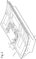
- Fig. 2 shows a stack 6 of laminates 2, 3 on a jig 5 during manufacture of a panel 1 according to the prior art from Fig. 1 .
- the manufacturing process starts with the preparation 11 of the various components of the final panel 1. These components comprise the layers of metal and the layers of fibres embedded in a precursor of an adhesive that make up the laminated skin 2 and the doubler 3 of the panel 1.
- the respective layers for forming the laminated skin 2 and for forming the doubler 3 are stacked on one another (steps 12 and 20).
- the layers of metal and the layers of fibres are stacked on one another in such a way that in each case at least one layer of fibres embedded in a precursor of an adhesive is included between two layers of metal.
- the stack for forming the skin is put in an autoclave (13), in which, under the effect of pressure and heat, the precursor of the adhesive in the layers of fibres is activated and the layers of metal and the layers of fibres are bonded together so that a laminated skin is produced.
- the formed skin 2 undergoes non-destructive inspection, for example by detecting inclusions of air, to check whether the skin meets the quality requirements (14). If the inspection is passed, the laminated skin undergoes material-removal machining (15), for example to make a precursor of a door opening and/or window opening 4.
- the stack for forming the doubler 3 is also put in an autoclave (21), in which, under the effect of pressure and heat, the precursor of the adhesive in the layers of fibres is activated and the layers of metal and the layers of fibres are bonded together so that the laminated doubler is produced.
- the formed doubler 3 undergoes non-destructive inspection, for example by detecting inclusions of air, to check whether the laminate meets the quality requirements (22). If the inspection is passed, the doubler undergoes material-removal machining (23), for example to make a precursor 7 of the final form of the doubler, and to bring the further edges of the laminated skin to size.
- the doubler 3 is stacked on the laminated skin 2 (30).
- a further layer of fibres embedded in a precursor of an adhesive is placed between the doubler 3 and the laminated skin 2.
- This third stack is put in an autoclave (31), in which, under the effect of pressure and heat, the precursor of the adhesive in the further layer of fibres is activated and the laminated skin and the doubler are bonded together so that the panel 1 is produced.
- the formed panel 1 undergoes non-destructive inspection, for example by detecting inclusions of air, to check whether the panel meets the quality requirements (32). If the inspection is passed, the panel undergoes mechanical testing (33).
- the panel undergoes finishing (40), including levelling of the surface and closing of various openings and cavities in the panel (41).
- finishing including levelling of the surface and closing of various openings and cavities in the panel (41).
- the panel is provided with a coat of paint (42).
- Fig. 3 shows a block diagram 100 of the manufacturing process for a panel 200 with doubler 310 according to the invention.
- Fig. 4 shows a stack 300 of layers on a jig 400 during manufacture of the panel 200 according to the invention.
- the manufacturing process again starts with preparation 101 of the various components of the final panel 200. These components comprise the layers of metal and the layers of fibres embedded in a precursor of an adhesive that make up the laminated skin 301 and the doubler 310 of the panel 200.
- the layers for forming the doubler 310 are stacked on one another (step 102).
- the layers of metal and the layers of fibres are stacked on one another in such a way that in each case at least one layer of fibres embedded in a precursor of an adhesive is included between two layers of metal.
- the stack for forming the doubler 310 is put in an autoclave (103), in which, under the effect of pressure and heat, the precursor of the adhesive in the layers of fibres is activated and the layers of metal and the layers of fibres are bonded together so that the laminated doubler 310 is produced.
- the formed doubler 310 undergoes non-destructive inspection, for example by detecting inclusions of air, to check whether the laminate meets the quality requirements (104). If the inspection is passed, the doubler undergoes material-removal machining (105), for example to make a precursor of the final form of the doubler.
- the doubler 310 is to be understood as the doubler shown 311 and the further doublers 312, 313, 314, 315, 316. These various doublers 311-316 form the complete doubler 310. At least one layer of fibres embedded in a precursor of an adhesive is placed in each case between two doublers 311-316, to form a supplementary adhesive layer between the doublers after activation.
- the layers for forming the laminated skin 301 are stacked on one another (110).
- the layers of metal and the layers of fibres are stacked on one another in such a way that in each case at least one layer of fibres embedded in a precursor of an adhesive is included between two layers of metal.
- a further layer of fibres embedded in a precursor of an adhesive is placed on the stack of the layers for the skin 301 (see Fig. 5 ).
- the doubler 310 is placed on this further layer of fibres, so that the further layer of fibres forms an intermediate layer between the stack and the doubler 310.
- the stack for forming the skin 301, the intermediate layer and the doubler 310 is put in an autoclave (111), in which, under the effect of pressure and heat, the precursor of the adhesive in the layers of fibres is activated and the layers of metal and the layers of fibres of the stack are bonded together so that a laminated skin 301 is produced. Furthermore, the precursor of the adhesive in the intermediate layer is activated so that the doubler is bonded to an outermost layer of metal of the laminated skin and the panel 200 is formed.
- the formed panel 200 undergoes non-destructive inspection, for example by detecting inclusions of air, to check whether the panel 1 meets the quality requirements (112). If the inspection is passed, the laminated skin undergoes material-removal machining (113) to obtain the final form of the panel.
- the panel undergoes mechanical testing (106) and then finishing (130), including levelling of the surface and closing of various openings and cavities in the panel (131).
- finishing including levelling of the surface and closing of various openings and cavities in the panel (131).
- the panel is provided with a coat of paint (132).
- steps 121, 122, 123 under block 120 are omitted. This means that in the manufacturing process according to the invention, compared to that according to the prior art from Fig. 1 , at least one stacking step 121, an autoclave step 122 and an inspection step 123 are omitted.
- Fig. 5 shows a cross-section of the panel 200 provided with the doubler 310 according to the invention.
- the complete doubler 310 consists of a single doubler 311.
- the doubler 311 comprises two layers of metal 320 between which there are two fibre-reinforced adhesive layers 321.
- the doubler 311 is provided on a laminated skin 301 that is formed from two layers of metal 304 with two fibre-reinforced adhesive layers 303 between them.
- the doubler 311 is bonded to the laminated skin 301 by means of the supplementary adhesive layer 340.
- This supplementary adhesive layer 340 consists of two fibre-reinforced intermediate adhesive layers 341.
- the final perimeter 342 of the intermediate layers 341 is set back from the perimeter 322 of the doubler 311.
- the space 343 that is thus created between the doubler 311 and the laminated skin 301 is filled with a layer of glue 330.
- This layer of glue 330 prevents the doubler 311 becoming detached at the perimeter 322 from the laminated skin 301 through detachment of the supplementary adhesive layer 340 from the laminated skin 301.
- the layer of glue 330 extends beyond the perimeter 322 of the doubler 311 and covers it on the full thickness.
- Fig. 6 shows a perspective view of the inside of a panel 200 provided with a doubler 310 comprising several strengthening layers 311-316, such as for an aircraft fuselage, according to the invention.
- the doubler 310 does not yet have the final form for assembly.
- the panel 200 comprises two parts 350, 360.
- a first part 350 is provided with positioning openings 370 (shown in Fig. 7 and shown schematically in Fig. 6 ), which for manufacturing the panel 200 are provided in the layers of the stack for forming the laminated skin and in the one or more doublers 311-316 that form the doubler 310.
- Positioning pins 380 are provided in the jig 400, see Fig.
- the positioning pins 380 and the positioning openings 370 provide good mutual alignment or positioning of the layers 304, 303 in the stack and of the stack with the doubler 310.
- the first part 350, provided with the positioning openings will be removed by material-removal machining from the second part 360. This second part 360 of the panel 200 then forms the panel ready for assembly.
- Fig. 7 shows a cross-section of the panel according to line VII-VII in Fig. 6 .
- the cross-section shows the panel 200 placed on the jig 400, wherein the jig 400 is provided with a positioning pin 380.
- the laminated skin 301 consisting of layers of metal 304 with a fibre-reinforced adhesive layer (not shown) in each case between two layers of metal, is provided with a positioning opening 370, into which the positioning pin 380 of the jig 400 fits.
- the complete doubler 310 comprises several doublers 311-314. In each case between two doublers 311-314, a supplementary adhesive layer 340 is provided for bonding between two doublers. Furthermore, a supplementary adhesive layer 340 of this kind is provided between the complete doubler and the laminated skin 301.
- the complete doubler is provided with a positioning opening 370 for receiving the positioning pin 380. This ensures that the complete doubler and the layers of the laminated skin 301 are aligned relative to one another.
- the positioning openings 370 are provided in the first part 350 of the panel 200, which after machining is removed from the second part 360 along the machining line 302. The second part 360 of the panel 200 then forms the panel ready for assembly.
Landscapes
- Engineering & Computer Science (AREA)
- Mechanical Engineering (AREA)
- Chemical & Material Sciences (AREA)
- Composite Materials (AREA)
- Architecture (AREA)
- Civil Engineering (AREA)
- Structural Engineering (AREA)
- Physics & Mathematics (AREA)
- Thermal Sciences (AREA)
- Quality & Reliability (AREA)
- Aviation & Aerospace Engineering (AREA)
- Laminated Bodies (AREA)
Description
- The invention relates to a method for manufacturing a panel for an aircraft structure, said panel being provided with a doubler, wherein the method comprises supplying the doubler in the form of a laminate of layers of metal and at least one fibre-reinforced adhesive layer in each case between two layers of metal, the at least two layers of metal being fastened together by means of said at least one fibre-reinforced adhesive layer.
- Such a method is known from the book: "Fibre Metal Laminates, an Introduction", edited by Ad Vlot et al., Kluwer 2001, pages 267-280, Chapter 17: "Detailed design concepts" by O.C. van der Jagt et al. This method describes the use of a doubler or thickening as a local reinforcing element. The doubler is placed on a laminated skin with a precursor of an adhesive layer between the doubler and the laminated skin, after which the laminated skin together with the doubler is put in an autoclave to activate the adhesive layer by means of increased pressure and temperature.
- This manner of manufacturing two laminates on one other is also described in
WO-02/094565-A1 - Panels for an aircraft structure comprise Fibre Metal Laminates (FML) - laminates which, as sandwich components of unidirectional glass-fibre prepregs, adhesive materials and thin metal plates, for example aluminium plates, are assembled together by stacking on a jig. A glass-fibre prepreg is a glass-fibre mat that is embedded in a matrix material. The metal plates with at least one fibre-reinforced adhesive layer in each case between two layers of metal are placed on top of each other on a jig. After the stacking process, the jig with the product is put in an autoclave. Then the product in the autoclave is glued together and cured under high pressure and high temperature. This results in a laminated product with a smooth jig side, which also forms the outside of the aircraft, the so-called laminated skin.
- For certain purposes it is desirable to reinforce the laminated skin, for example as local reinforcement at a door or window opening. Such reinforcement is obtained by local attachment of a further laminate on the surface of the laminated skin. The laminated skin is then thickened in the location of the attached further laminate. The further laminate is also called a doubler or thickening.
- A disadvantage of the method described above is that both the laminated skin and the doubler undergo a first activation step, for example in an autoclave, to form a laminate. After placement of the doubler on the laminated skin, with a precursor of an adhesive layer between them, this assembly undergoes an activation step again, for example in the same autoclave. Such a method is time-consuming because the same process steps must take place three times before the panel being manufactured is ready. Furthermore, this method has an adverse effect on the production capacity of the equipment used, such as the jig that is used.
-
US2014/087143 discloses a method for manufacturing a panel (6,7) wherein on the left side (41), seen from the top downwards, layers 36/37/36 are a doubler, layer 37 there below is a further fiber layer (340) and the bottom seven layers 36/37/36/37/36/37/36 being in contact with mould (16) are an assembly of metal layers and fiber layers located in a mould. Layers 36/37 form a fiber/metal laminate (FML), wherein layer 36 is in the form of a sheet of an AlMgSc alloy and layer 37 is a sheet of reinforcing fibres in a thermoplastic plastics material. The semi-finished product (7) is shaped (creep process) in mould (16) to a structural assembly (6) under pressure and temperature. Pressure is applied by means of a vacuum bag. The temperature during the creep forming is selected in such a way that the individual layers 36 are interconnected by melting thethermoplastic plastics material 13 in the layers 37 at least in part, and is preferably between 275°C and 375°C. - The aim of the invention is to provide a method that does not have the aforementioned disadvantages. For this purpose, this method comprises the following steps:
- supplying the doubler in the form of a laminate of layers of metal and at least one fibre-reinforced adhesive layer in each case between two layers of metal, the at least two layers of metal being fastened together by means of said at least one fibre-reinforced adhesive layer,
- supplying a jig,
- supplying, in the jig, a stack of layers of metal and layers of fibres embedded in a precursor of an adhesive placed in each case between two layers of metal, for forming a skin,
- placing a further layer of fibres embedded in a precursor of an adhesive on the stack,
- placing the doubler on the further layer of fibres embedded in a precursor of an adhesive, so that the further layer of fibres embedded in a precursor of an adhesive forms an intermediate layer between the stack and the doubler,
- placing an air-tight covering layer on top of the stack, the intermediate layer and the doubler, thereby forming a space between the jig and the covering layer,
- air-tight closure of the covering layer around the perimeter of the stack, the intermediate layer and the doubler with respect to the jig,
- placing the jig with the stack, the intermediate layer and the doubler as well as the sealed covering layer in an autoclave,
- lowering the pressure in the space between the jig and the covering layer,
- under the effect of heat and pressure in the autoclave, gluing the layers of metal together by activating the precursor of the adhesive of each embedded layer of fibres, with formation of a laminated skin, as well as simultaneous activation, under the effect of the heat and pressure in the autoclave, of the precursor of the adhesive of the further layer of fibres in the intermediate layer with formation of a supplementary adhesive layer, by means of which the doubler is bonded to the laminated skin, thereby forming the panel,
- removing the panel from the autoclave,
- causing the perimeter of the further layer of fibres (342) to recede relative to the perimeter (322) of the doubler,
- filling the space (343) delimited by the doubler, the stack and the perimeter of the further layer of fibres with glue, forming a glued edge (330),
- activating the glued edge under the effect of heat in the autoclave.
- The method according to the invention has the advantage that the step of laminating the skin takes place at the same time as bonding the doubler to the laminated skin. Because these process steps are carried out at the same time, the production time is reduced. Furthermore, this method has the advantage that the occupancy time of the jigs per panel is shorter. This logistic advantage follows because the jigs are now only required for assembling the panel, instead of for assembling both the laminated skin and the panel.
- The laminate of layers of metal and at least one fibre-reinforced adhesive layer in each case between two layers of metal that forms the doubler is manufactured beforehand by means of a known process for an autoclaved laminate - the stack is cured in the form of a laminate, or by a process described below. The doubler is applied on a stack of layers of metal with, in each case between two layers of metal, layers of fibres embedded in a precursor of an adhesive. An intermediate layer of a further layer of fibres embedded in a precursor of an adhesive is provided between the stack and the doubler. After laminating, the stack forms the laminated skin to which the doubler with the intermediate layer is bonded.
- The whole of the stack, the intermediate layer and the doubler is formed in a jig and is covered air-tight with an air-tight coating, so that a space forms between the jig and the air-tight coating. The pressure in this space is lowered relative to the ambient pressure. The whole of the jig, the stack, the intermediate layer, the doubler and the air-tight coating is subjected to heat and pressure, in an autoclave. During this, a laminated skin of the stack is formed by activating the precursor of the adhesive of each embedded layer of fibres between the layers of metal. Furthermore, simultaneously, the precursor of the adhesive of the further layer of fibres in the intermediate layer is activated, whereby a supplementary adhesive layer is formed, by means of which the doubler is bonded to the laminated skin.
- After laminating the stack and bonding the doubler to the skin, the panel is formed. The panel is removed from the autoclave, so that it can cool down and be processed further.
- The aforementioned method comprises the steps of:
- causing the perimeter of the further layer of fibres to recede relative to the perimeter of the doubler,
- filling the space delimited by the doubler, the stack and the perimeter of the further layer of fibres with glue, forming a glued edge,
- activating the glued edge under the effect of heat in the autoclave.
- The further layer of fibres may have smaller dimensions than the doubler, so that the perimeter of the further layer of fibres is set back relative to the perimeter of the doubler. In other words: the perimeter of the doubler extends beyond the perimeter of the further layer of fibres. A space is now formed between the doubler, the stack and the perimeter of the further layer of fibres. This space is filled with glue, finally giving good bonding of the doubler with the laminated skin to the perimeter. This bonding is activated in the autoclave, simultaneously with forming the panel.
- The advantage of using glue in the space between the doubler, the stack and the perimeter of the further layer of fibres is that this prevents the doubler becoming detached from the laminated skin at the perimeter. This is in contrast to the situation in which the further layer of fibres extends to or beyond the perimeter of the doubler and the adhesive layer that arose between the doubler and the laminated skin after autoclaving may become detached from the laminated skin.
- According to an embodiment, the method comprises the step of:
- after removal of the panel from the autoclave, simultaneous material-removal machining from a combined edge part of the laminated skin and the doubler of the panel to provide a predetermined nominal edge shape and dimensioning of the panel.
- By simultaneous material-removal machining of a combined edge part of the laminated skin and the doubler after forming the panel, only a single processing step is necessary for such processing, namely finishing the combined edge part to size for example by milling. After this simultaneous machining the edge of the doubler is perfectly aligned with the edge of the laminated skin.
- Preferably the method further comprises:
- providing positioning openings in the doubler,
- providing positioning openings in the layers of metal and embedded layers of fibres for forming the skin,
- aligning said positioning openings in the doubler and in the skin in the jig relative to each other,
- fastening positioning pins to the jig that extend through said positioning openings in the doubler and in the skin.
- The positioning openings are used for aligning the doubler and the layers forming the stack in the jig. Positioning pins are provided in the jig for this. These positioning pins pass through the positioning openings of the doubler and the layers of the stack. For the layers of the stack, the positioning pins have some clearance with the positioning openings in the layers of the stack, so as to be able to offer the layers of metal in the stack the necessary room to move during autoclaving. The layers of metal may then "settle", wherein the layers of metal may move somewhat laterally relative to the jig and relative to each other.
- Preferably the method further comprises:
- manufacturing a doubler and a skin with oversize with formation of a supplementary region into which both the skin and the doubler extend,
- providing the positioning openings through the skin and the doubler of the panel in the location of the supplementary region,
- removing the supplementary region, with formation of an edge of the panel.
- The doubler and the stack are prepared oversize in the jig. This oversize creates a supplementary region during forming of the panel. After removal of the panel from the autoclave, this supplementary region can be removed by material-removal machining. When the positioning openings in the doubler and the stack are finally provided in the location of the supplementary region, on removal of the supplementary region these openings are also removed.
- The method may further comprise manufacture of the doubler, by:
- supplying a supplementary jig,
- supplying, in the supplementary jig, a supplementary stack of layers of metal and layers of fibres embedded in a precursor of an adhesive included in each case between two layers of metal,
- placing an air-tight covering layer over the supplementary stack, thereby forming a space between the supplementary jig and the covering layer,
- air-tight closure of the covering layer around the perimeter of the supplementary stack relative to the supplementary jig,
- putting the supplementary jig with the supplementary stack in an autoclave,
- lowering the pressure in the space between the supplementary jig and the covering layer,
- under the effect of heat and pressure in the autoclave, gluing the layers of metal together by activating the precursor of the adhesive of each layer of fibres, with formation of a doubler in the form of a laminate from layers of metal and at least one fibre-reinforced adhesive layer in each case between two layers of metal,
- removing the doubler from the autoclave.
- The doubler is formed from a prefabricated laminate, wherein the precursor of the adhesive of each layer of fibres is activated and a fibre-reinforced adhesive layer forms in each case between two layers of metal. Because the doubler is already formed as a laminate, when manufacturing the panel, only the laminated skin and the bonding between the laminated skin and the doubler need to be formed.
- According to an embodiment of the method, supplying the doubler in the form of a laminate comprises manufacture of the doubler by the steps of:
- supplying a supplementary stack of layers of metal and layers of fibres embedded in a precursor of an adhesive included in each case between two layers of metal, and
- placing the supplementary stack on the intermediate layer,
- In this embodiment, the doubler is then formed as a supplementary stack on the intermediate layer that forms on the laminated skin during autoclaving of the doubler. Such a method has the advantage that the doubler no longer needs to be manufactured beforehand and that only one autoclaving step needs to take place in the process.
- Preferably each layer of metal of the supplementary stack then has a smaller perimeter than an underlying layer of metal of the supplementary stack. This means that each successive layer of metal has a smaller area. At least one part of the peripheral edge of each successive layer of metal is staggered relative to a peripheral edge of the underlying layer of metal.
- According to an embodiment, the method comprises applying a doubler that has a smaller perimeter than the skin. The doubler may have a smaller perimeter locally than the skin, i.e. at least one part of the peripheral edge of the doubler is staggered relative to a peripheral edge of the skin. Such a step has the advantage that the laminated skin may be provided with strengthening locally, for example at the site of a door or window opening or a cargo hatch.
- The method may further comprise, before placing an air-tight covering layer over the stack, the intermediate layer and the doubler, the step of placing a further intermediate layer on a free side of the doubler, wherein the further intermediate layer comprises a further layer of fibres embedded in a precursor of an adhesive, and a further doubler on the further intermediate layer.
- Such a step may be applied if several doublers are necessary for the desired strengthening, in other words when a single doubler does not provide the desired strengthening.
- The invention further relates to a panel for an aircraft structure, manufactured according to the method described above, said panel comprising a laminated skin of layers of metal, in each case two of which are joined together by a fibre-reinforced adhesive layer, as well as a laminated doubler of layers of metal and at least one fibre-reinforced adhesive layer in each case between two layers of metal, wherein said doubler has a smaller size of perimeter than the skin and is bonded to an outermost layer of metal of the laminated skin by a fibre-reinforced supplementary adhesive layer, wherein at least one part of the perimeter of the fibre-reinforced supplementary adhesive layer is staggered inwards relative to the corresponding perimeter of the doubler and wherein that part of the inwards-staggered perimeter of the fibre-reinforced supplementary adhesive layer is delimited by a glued edge.
- The fibre-reinforced supplementary adhesive layer has smaller dimensions than the doubler, so that at least one part of the perimeter of the fibre-reinforced supplementary adhesive layer is set back relative to the perimeter of the doubler. In other words: the perimeter of the doubler extends beyond this part of the perimeter of the fibre-reinforced supplementary adhesive layer. The space formed between the doubler, the laminated skin and the perimeter of the fibre-reinforced supplementary adhesive layer is filled with glue for good bonding to the perimeter of the doubler and the laminated skin. The advantage of using glue in this space between the doubler, the laminated skin and the perimeter of the fibre-reinforced supplementary adhesive layer is that this prevents the doubler becoming detached from the laminated skin at the perimeter. This is in contrast to the situation in which the fibre-reinforced supplementary adhesive layer extends to or beyond the perimeter of the doubler and wherein the fibre-reinforced supplementary adhesive layer between the doubler and the laminated skin may become detached from the laminated skin.
- The panel may further comprise a further laminated doubler, wherein said further doubler has a smaller size of perimeter than the skin and/or the laminated doubler and is bonded to an outermost layer of metal of the laminated doubler by a fibre-reinforced supplementary adhesive layer, wherein at least one part of the perimeter of the fibre-reinforced supplementary adhesive layer is staggered inwards relative to the corresponding perimeter of the further doubler and wherein that part of the inwards-staggered perimeter of the fibre-reinforced supplementary adhesive layer is delimited by a glued edge.
- With such a panel, several doublers are used for strengthening. This may be advantageous when several doublers are necessary for the desired strengthening, in other words when a single doubler does not provide the desired strengthening of the panel.
- According to an embodiment, the glued edge may extend to, or beyond, said corresponding perimeter of the doubler. When the glued edge extends beyond the doubler, an end face of an end edge of the doubler may be embedded in the glue, so that the fibres of the fibre-reinforced adhesive layer of the doubler cannot protrude from the end face.
- The panel may further comprise a first part of the perimeter of the doubler bordering on and coinciding with a part of an edge of the skin, with a second part of the perimeter of the doubler located at a distance from the edge of the skin, wherein the supplementary adhesive layer extends to the first part of the perimeter of the doubler and wherein the supplementary adhesive layer is staggered inwards relative to the second part of the perimeter of the doubler.
- When the edge parts of the laminated skin and the doubler coincide, detachment of the adhesive layer from the laminated skin does not occur. For this reason, at the location of such coinciding of these edge parts, the supplementary adhesive layer may extend to the edge part of the skin, and therefore to the perimeter of the doubler. Coinciding of the laminated skin and the doubler may arise through material-removal machining of the panel. As a result, the coinciding edge parts of the skin and the doubler are perfectly aligned with each other. A glued edge as described above is not then necessary.
- Preferably the glued edge is located exclusively at the location of the inwards-staggered part of the supplementary adhesive layer on the second part of the perimeter of the doubler, which is at a distance from an edge of the skin.
- The invention further relates to an aircraft comprising a panel as described above. The invention will be explained further hereunder, on the basis of the figures.
-
Fig. 1 shows a block diagram of the manufacturing process for a panel with doubler according to the prior art. -
Fig. 2 shows a stack of laminates on a jig during manufacture according to the prior art. -
Fig. 3 shows a block diagram of the manufacturing process for a panel with doubler according to the invention. -
Fig. 4 shows a stack of layers on a jig during manufacture according to the invention. -
Fig. 5 shows a cross-section of a panel provided with a doubler according to the invention. -
Fig. 6 shows a perspective view of the inside of a panel provided with several doublers, such as for an aircraft fuselage, according to the invention. -
Fig. 7 shows a cross-section of the panel according toFig. 6 . -
Fig. 1 shows, in a block diagram 10, the manufacturing process for apanel 1, seeFig. 2 , according to the prior art.Fig. 2 shows astack 6 oflaminates 2, 3 on ajig 5 during manufacture of apanel 1 according to the prior art fromFig. 1 . The manufacturing process starts with thepreparation 11 of the various components of thefinal panel 1. These components comprise the layers of metal and the layers of fibres embedded in a precursor of an adhesive that make up thelaminated skin 2 and the doubler 3 of thepanel 1. After thepreparatory steps 11, the respective layers for forming thelaminated skin 2 and for forming the doubler 3 are stacked on one another (steps 12 and 20). During stacking for both components, the layers of metal and the layers of fibres are stacked on one another in such a way that in each case at least one layer of fibres embedded in a precursor of an adhesive is included between two layers of metal. - The stack for forming the skin is put in an autoclave (13), in which, under the effect of pressure and heat, the precursor of the adhesive in the layers of fibres is activated and the layers of metal and the layers of fibres are bonded together so that a laminated skin is produced. The formed
skin 2 undergoes non-destructive inspection, for example by detecting inclusions of air, to check whether the skin meets the quality requirements (14). If the inspection is passed, the laminated skin undergoes material-removal machining (15), for example to make a precursor of a door opening and/or window opening 4. - The stack for forming the doubler 3 is also put in an autoclave (21), in which, under the effect of pressure and heat, the precursor of the adhesive in the layers of fibres is activated and the layers of metal and the layers of fibres are bonded together so that the laminated doubler is produced. The formed doubler 3 undergoes non-destructive inspection, for example by detecting inclusions of air, to check whether the laminate meets the quality requirements (22). If the inspection is passed, the doubler undergoes material-removal machining (23), for example to make a
precursor 7 of the final form of the doubler, and to bring the further edges of the laminated skin to size. - After separate manufacture of the
laminated skin 2 and the doubler 3, the doubler 3 is stacked on the laminated skin 2 (30). A further layer of fibres embedded in a precursor of an adhesive is placed between the doubler 3 and thelaminated skin 2. This third stack is put in an autoclave (31), in which, under the effect of pressure and heat, the precursor of the adhesive in the further layer of fibres is activated and the laminated skin and the doubler are bonded together so that thepanel 1 is produced. The formedpanel 1 undergoes non-destructive inspection, for example by detecting inclusions of air, to check whether the panel meets the quality requirements (32). If the inspection is passed, the panel undergoes mechanical testing (33). - After this material-removal machining, the panel undergoes finishing (40), including levelling of the surface and closing of various openings and cavities in the panel (41). Before the panel can be transported (43) to the assembly station, the panel is provided with a coat of paint (42).
-
Fig. 3 shows a block diagram 100 of the manufacturing process for apanel 200 withdoubler 310 according to the invention.Fig. 4 shows astack 300 of layers on ajig 400 during manufacture of thepanel 200 according to the invention. The manufacturing process again starts withpreparation 101 of the various components of thefinal panel 200. These components comprise the layers of metal and the layers of fibres embedded in a precursor of an adhesive that make up thelaminated skin 301 and thedoubler 310 of thepanel 200. After thepreparatory steps 101, first the layers for forming thedoubler 310 are stacked on one another (step 102). During stacking of the layers for thedoubler 310, the layers of metal and the layers of fibres are stacked on one another in such a way that in each case at least one layer of fibres embedded in a precursor of an adhesive is included between two layers of metal. - The stack for forming the
doubler 310 is put in an autoclave (103), in which, under the effect of pressure and heat, the precursor of the adhesive in the layers of fibres is activated and the layers of metal and the layers of fibres are bonded together so that thelaminated doubler 310 is produced. The formeddoubler 310 undergoes non-destructive inspection, for example by detecting inclusions of air, to check whether the laminate meets the quality requirements (104). If the inspection is passed, the doubler undergoes material-removal machining (105), for example to make a precursor of the final form of the doubler. Thedoubler 310 is to be understood as the doubler shown 311 and thefurther doublers complete doubler 310. At least one layer of fibres embedded in a precursor of an adhesive is placed in each case between two doublers 311-316, to form a supplementary adhesive layer between the doublers after activation. - Then the layers for forming the
laminated skin 301 are stacked on one another (110). During stacking of the layers for forming theskin 301, the layers of metal and the layers of fibres are stacked on one another in such a way that in each case at least one layer of fibres embedded in a precursor of an adhesive is included between two layers of metal. A further layer of fibres embedded in a precursor of an adhesive is placed on the stack of the layers for the skin 301 (seeFig. 5 ). Then thedoubler 310 is placed on this further layer of fibres, so that the further layer of fibres forms an intermediate layer between the stack and thedoubler 310. - The stack for forming the
skin 301, the intermediate layer and thedoubler 310 is put in an autoclave (111), in which, under the effect of pressure and heat, the precursor of the adhesive in the layers of fibres is activated and the layers of metal and the layers of fibres of the stack are bonded together so that alaminated skin 301 is produced. Furthermore, the precursor of the adhesive in the intermediate layer is activated so that the doubler is bonded to an outermost layer of metal of the laminated skin and thepanel 200 is formed. The formedpanel 200 undergoes non-destructive inspection, for example by detecting inclusions of air, to check whether thepanel 1 meets the quality requirements (112). If the inspection is passed, the laminated skin undergoes material-removal machining (113) to obtain the final form of the panel. - After this material-removal machining, the panel undergoes mechanical testing (106) and then finishing (130), including levelling of the surface and closing of various openings and cavities in the panel (131). Before the panel can be transported (133) to the assembly station, the panel is provided with a coat of paint (132).
- As shown in
Fig. 3 ,steps block 120 are omitted. This means that in the manufacturing process according to the invention, compared to that according to the prior art fromFig. 1 , at least one stackingstep 121, anautoclave step 122 and aninspection step 123 are omitted. -
Fig. 5 shows a cross-section of thepanel 200 provided with thedoubler 310 according to the invention. Thecomplete doubler 310 consists of asingle doubler 311. Thedoubler 311 comprises two layers ofmetal 320 between which there are two fibre-reinforced adhesive layers 321. Thedoubler 311 is provided on alaminated skin 301 that is formed from two layers of metal 304 with two fibre-reinforcedadhesive layers 303 between them. Thedoubler 311 is bonded to thelaminated skin 301 by means of the supplementaryadhesive layer 340. This supplementaryadhesive layer 340 consists of two fibre-reinforced intermediate adhesive layers 341. As shown inFig. 5 , thefinal perimeter 342 of the intermediate layers 341 is set back from theperimeter 322 of thedoubler 311. Thespace 343 that is thus created between thedoubler 311 and thelaminated skin 301 is filled with a layer ofglue 330. This layer ofglue 330 prevents thedoubler 311 becoming detached at theperimeter 322 from thelaminated skin 301 through detachment of the supplementaryadhesive layer 340 from thelaminated skin 301. The layer ofglue 330 extends beyond theperimeter 322 of thedoubler 311 and covers it on the full thickness. -
Fig. 6 shows a perspective view of the inside of apanel 200 provided with adoubler 310 comprising several strengthening layers 311-316, such as for an aircraft fuselage, according to the invention. After manufacture of thepanel 200 in the autoclave, thedoubler 310 does not yet have the final form for assembly. After manufacture, thepanel 200 comprises twoparts first part 350 is provided with positioning openings 370 (shown inFig. 7 and shown schematically inFig. 6 ), which for manufacturing thepanel 200 are provided in the layers of the stack for forming the laminated skin and in the one or more doublers 311-316 that form thedoubler 310. Positioning pins 380 are provided in thejig 400, seeFig. 7 , which are included in thepositioning openings 370 of the various components during stacking in thejig 400. The interaction between the positioning pins 380 and thepositioning openings 370 provides good mutual alignment or positioning of thelayers 304, 303 in the stack and of the stack with thedoubler 310. After manufacture of thepanel 200, thefirst part 350, provided with the positioning openings, will be removed by material-removal machining from thesecond part 360. Thissecond part 360 of thepanel 200 then forms the panel ready for assembly. -
Fig. 7 shows a cross-section of the panel according to line VII-VII inFig. 6 . The cross-section shows thepanel 200 placed on thejig 400, wherein thejig 400 is provided with apositioning pin 380. Thelaminated skin 301, consisting of layers of metal 304 with a fibre-reinforced adhesive layer (not shown) in each case between two layers of metal, is provided with apositioning opening 370, into which thepositioning pin 380 of thejig 400 fits. Thecomplete doubler 310 comprises several doublers 311-314. In each case between two doublers 311-314, a supplementaryadhesive layer 340 is provided for bonding between two doublers. Furthermore, a supplementaryadhesive layer 340 of this kind is provided between the complete doubler and thelaminated skin 301. - The complete doubler is provided with a
positioning opening 370 for receiving thepositioning pin 380. This ensures that the complete doubler and the layers of thelaminated skin 301 are aligned relative to one another. The positioningopenings 370 are provided in thefirst part 350 of thepanel 200, which after machining is removed from thesecond part 360 along themachining line 302. Thesecond part 360 of thepanel 200 then forms the panel ready for assembly.
Claims (15)
- Method for manufacturing a panel (200) for an aircraft structure,
said panel being provided with a doubler (310, 311), wherein the method comprises:- supplying the doubler in the form of a laminate of layers of metal (320) and at least one fibre-reinforced adhesive layer (321) in each case between two layers of metal, and by means of said at least one fibre-reinforced adhesive layer the at least two layers of metal are fastened together,- supplying a jig (400),- supplying, in the jig, a stack of layers of metal (304) and layers of fibres (303) embedded in a precursor of an adhesive included in each case between two layers of metal to form a skin (301),- placing a further layer of fibres (340) embedded in a precursor of an adhesive on the stack,- placing the doubler on the further layer of fibres embedded in a precursor of an adhesive, so that the further layer of fibres embedded in a precursor of an adhesive forms an intermediate layer between the stack and the doubler,- placing an air-tight covering layer over the stack, the intermediate layer and the doubler, thereby forming a space between the jig and the covering layer,- air-tight closure of the covering layer around the perimeter of the stack, the intermediate layer and the doubler with respect to the jig,- putting the jig with the stack, the intermediate layer and the doubler as well as the sealed covering layer in an autoclave,- lowering the pressure in the space between the jig and the covering layer,- under the effect of heat and pressure in the autoclave, gluing the layers of metal together by activating the precursor of the adhesive of each embedded layer of fibres with formation of a laminated skin, as well as simultaneously, under the effect of the heat and pressure in the autoclave, activating the precursor of the adhesive of the further layer of fibres in the intermediate layer with formation of a supplementary adhesive layer, by means of which the doubler is bonded to the laminated skin, thereby forming the panel,- removing the panel from the autoclave,the method further comprising the steps of:- causing the perimeter of the further layer of fibres (342) to recede relative to the perimeter (322) of the doubler,- filling the space (343) delimited by the doubler, the stack and the perimeter of the further layer of fibres with glue, forming a glued edge (330),- activating the glued edge under the effect of heat in the autoclave. - Method according to Claim 1, comprising the step of:- after removal of the panel from the autoclave, simultaneous material-removal machining of a combined edge part of the laminated skin and the doubler of the panel to provide a predetermined nominal edge shape and dimensioning of the panel.
- Method according to any one of the preceding claims, further comprising:- providing positioning openings (370) in the doubler,- providing positioning openings (370) in the layers of metal and embedded layers of fibres for forming the skin,- in the jig, aligning said positioning openings in the doubler and in the skin relative to one another,- fastening positioning pins (380) to the jig that extend through said positioning openings in the doubler and in the skin.
- Method according to Claims 2 and 3, further comprising:- manufacturing a doubler (310, 311) and a skin (301) with oversize with formation of a supplementary region (350) into which both the skin and the doubler extend,- providing the positioning openings (370) through the skin and the doubler of the panel in the location of the supplementary region,- removing the supplementary region with formation of an edge of the panel.
- Method according to any one of the preceding claims, comprising manufacturing the doubler by the steps of:- supplying a supplementary jig,- supplying, in the supplementary jig, a supplementary stack of layers of metal and layers of fibres embedded in a precursor of an adhesive included in each case between two layers of metal,- placing an air-tight covering layer over the supplementary stack, thereby forming a space between the supplementary jig and the covering layer,- air-tight closure of the covering layer around the perimeter of the supplementary stack relative to the supplementary jig,- putting the supplementary jig with the supplementary stack in an autoclave,- lowering the pressure in the space between the supplementary jig and the covering layer,- under the effect of heat and pressure in the autoclave, gluing the layers of metal together by activating the precursor of the adhesive of each layer of fibres, with formation of a doubler in the form of a laminate of layers of metal and at least one fibre-reinforced adhesive layer in each case between two layers of metal,- removing the doubler from the autoclave.
- Method according to any one of Claims 1-4, wherein supplying the doubler in the form of a laminate comprises manufacturing the doubler by the steps of:- supplying a supplementary stack of layers of metal and layers of fibres embedded in a precursor of an adhesive included in each case between two layers of metal, and- placing the supplementary stack on the intermediate layer,wherein during the step of gluing the layers of metal together under the effect of heat and pressure by activating the precursor of the adhesive of each layer of fibres, a doubler is formed in the form of a laminate of layers of metal and at least one fibre-reinforced adhesive layer in each case between two layers of metal on the laminated skin.
- Method according to Claim 6, wherein each layer of metal of the supplementary stack has a smaller perimeter than an underlying layer of metal of the supplementary stack.
- Method according to any one of the preceding claims, comprising applying a doubler that has a smaller perimeter than the skin.
- Method according to any one of the preceding claims, comprising, before placing an air-tight covering layer over the stack, the intermediate layer and the doubler, the step of placing a further intermediate layer (340) on a free side of the doubler, wherein the further intermediate layer comprises a further layer of fibres embedded in a precursor of an adhesive, and placing a further doubler (312-316) on the further intermediate layer.
- Panel (200) for an aircraft structure, manufactured according to the method of any one of Claims 1-9, said panel comprising a laminated skin (301) of layers of metal (304), of which in each case two are joined together by a fibre-reinforced adhesive layer (303), as well as a laminated doubler (310, 311) of layers of metal (320) and at least one fibre-reinforced adhesive layer (321) in each case between two layers of metal, where said doubler has a smaller size of perimeter than the skin and is bonded to an outermost layer of metal of the laminated skin by a fibre-reinforced supplementary adhesive layer (340), wherein at least one part of the perimeter (342) of the fibre-reinforced supplementary adhesive layer is staggered inwards relative to the corresponding perimeter of the doubler and wherein that part of the inwards-staggered perimeter of the fibre-reinforced supplementary adhesive layer is delimited by a glued edge (330).
- Panel according to Claim 10, further comprising a further laminated doubler (312-316), wherein said further doubler has a smaller size of perimeter than the skin and/or the laminated doubler and is bonded to an outermost layer of metal of the laminated doubler by a fibre-reinforced supplementary adhesive layer (340), wherein at least one part of the perimeter of the fibre-reinforced supplementary adhesive layer is staggered inwards relative to the corresponding perimeter of the further doubler and wherein that part of the inwards-staggered perimeter of the fibre-reinforced supplementary adhesive layer is delimited by a glued edge.
- Panel according to Claim 10 or 11, wherein the glued edge extends to, or beyond, said corresponding perimeter of the doubler.
- Panel according to any one of Claims 10-12, wherein a first part of the perimeter of the doubler borders on and coincides with a part of an edge of the skin and a second part of the perimeter of the doubler is located at a distance from the edge of the skin, wherein the supplementary adhesive layer extends to the first part of the perimeter of the doubler and wherein the supplementary adhesive layer is staggered inwards relative to the second part of the perimeter of the doubler.
- Panel according to Claim 13, wherein the glued edge is located exclusively at the location of the inwards-staggered part of the supplementary adhesive layer on the second part of the perimeter of the doubler, which is located at a distance from the edge of the skin.
- Aircraft comprising a panel according to any one of Claims 10-14.
Applications Claiming Priority (1)
| Application Number | Priority Date | Filing Date | Title |
|---|---|---|---|
| NL2017062A NL2017062B1 (en) | 2016-06-28 | 2016-06-28 | Method for manufacturing a panel with thickening |
Publications (2)
| Publication Number | Publication Date |
|---|---|
| EP3263328A1 EP3263328A1 (en) | 2018-01-03 |
| EP3263328B1 true EP3263328B1 (en) | 2019-01-30 |
Family
ID=56738164
Family Applications (1)
| Application Number | Title | Priority Date | Filing Date |
|---|---|---|---|
| EP17178154.5A Active EP3263328B1 (en) | 2016-06-28 | 2017-06-27 | Method for manufacturing a panel with a doubler |
Country Status (4)
| Country | Link |
|---|---|
| US (1) | US10556664B2 (en) |
| EP (1) | EP3263328B1 (en) |
| CN (1) | CN107539496B (en) |
| NL (1) | NL2017062B1 (en) |
Families Citing this family (1)
| Publication number | Priority date | Publication date | Assignee | Title |
|---|---|---|---|---|
| FR3015329B1 (en) * | 2013-12-19 | 2016-05-20 | Aerolia | METHOD, DEVICE AND SYSTEM FOR ASSEMBLING A PLURALITY OF PANELS |
Family Cites Families (7)
| Publication number | Priority date | Publication date | Assignee | Title |
|---|---|---|---|---|
| NL8100087A (en) * | 1981-01-09 | 1982-08-02 | Tech Hogeschool Delft Afdeling | LAMINATE OF METAL PLATES AND CONNECTED WIRES. |
| NL1018120C2 (en) * | 2001-05-21 | 2002-12-03 | Fokker Aerostructures Bv | Method for manufacturing a molded laminate. |
| NL1024076C2 (en) * | 2003-08-08 | 2005-02-10 | Stork Fokker Aesp Bv | Method for forming a laminate with a recess. |
| US7115323B2 (en) * | 2003-08-28 | 2006-10-03 | The Boeing Company | Titanium foil ply replacement in layup of composite skin |
| DE102006007429B4 (en) * | 2006-02-17 | 2011-08-18 | Airbus Operations GmbH, 21129 | Method for autoclave-free bonding of components for aircraft |
| US20090211697A1 (en) * | 2007-05-15 | 2009-08-27 | Heinimann Markus B | Reinforced hybrid structures and methods thereof |
| DE102011006032A1 (en) * | 2011-03-24 | 2012-09-27 | Airbus Operations Gmbh | Process for producing a structural component and structural component |
-
2016
- 2016-06-28 NL NL2017062A patent/NL2017062B1/en active
-
2017
- 2017-06-27 US US15/633,926 patent/US10556664B2/en active Active
- 2017-06-27 EP EP17178154.5A patent/EP3263328B1/en active Active
- 2017-06-28 CN CN201710508034.5A patent/CN107539496B/en active Active
Non-Patent Citations (1)
| Title |
|---|
| None * |
Also Published As
| Publication number | Publication date |
|---|---|
| NL2017062B1 (en) | 2018-01-05 |
| CN107539496A (en) | 2018-01-05 |
| US20170369145A1 (en) | 2017-12-28 |
| EP3263328A1 (en) | 2018-01-03 |
| CN107539496B (en) | 2022-08-09 |
| US10556664B2 (en) | 2020-02-11 |
Similar Documents
| Publication | Publication Date | Title |
|---|---|---|
| EP1555204B1 (en) | Wing of composite material and method of fabricating the same | |
| EP2318466B1 (en) | Method for manufacturing a composite structure and intermediate composite structure | |
| EP2253460B1 (en) | Method of joining composite components | |
| US9096021B2 (en) | Method and shaping device for producing a composite fiber component for air and space travel | |
| US8192574B1 (en) | Process for bonding a vented hollow component | |
| CN103803054A (en) | Joint for composite wings | |
| JP6583966B2 (en) | Panel made of laminate and method for producing the same | |
| EP1504888A1 (en) | Method for forming a laminate with a rebate | |
| CA2943533C (en) | Method and assembly for manufacturing door skin and wall with doorway | |
| JP2023054346A (en) | Fabrication of fiber reinforced composite structures | |
| US20080115887A1 (en) | Method for forming a feature in a piece of composite material | |
| EP2221168A1 (en) | Method of making a window skin panel | |
| US20190177007A1 (en) | Composite repair kit | |
| CN101443233A (en) | Reinforced hybrid structures and methods thereof | |
| JP4328579B2 (en) | Method for manufacturing honeycomb sandwich panel | |
| US20040075023A1 (en) | Lightweight structural component made of metallic ply materials | |
| KR20140073386A (en) | Magnetic reinforce plate | |
| JP5733661B2 (en) | Double curved sandwich panel | |
| US10556664B2 (en) | Method for manufacturing a panel with a doubler | |
| EP2008796A1 (en) | Method for producing composite-material structures with collapsible tooling of inert material | |
| US6565690B1 (en) | Process for manufacturing structures of composite material | |
| JP7034849B2 (en) | Composite material, method for manufacturing composite material, and method for curing composite material | |
| JP3004309B2 (en) | Method for producing fiber-reinforced resin laminate | |
| EP3812138B1 (en) | Method of manufacture of an integrally stiffened bonded panel with machined pockets | |
| JP2001315228A (en) | Method for manufacturing honeycomb sandwich structure using composite material and forming jig used for manufacturing the honeycomb sandwich structure |
Legal Events
| Date | Code | Title | Description |
|---|---|---|---|
| PUAI | Public reference made under article 153(3) epc to a published international application that has entered the european phase |
Free format text: ORIGINAL CODE: 0009012 |
|
| STAA | Information on the status of an ep patent application or granted ep patent |
Free format text: STATUS: THE APPLICATION HAS BEEN PUBLISHED |
|
| AK | Designated contracting states |
Kind code of ref document: A1 Designated state(s): AL AT BE BG CH CY CZ DE DK EE ES FI FR GB GR HR HU IE IS IT LI LT LU LV MC MK MT NL NO PL PT RO RS SE SI SK SM TR |
|
| AX | Request for extension of the european patent |
Extension state: BA ME |
|
| STAA | Information on the status of an ep patent application or granted ep patent |
Free format text: STATUS: REQUEST FOR EXAMINATION WAS MADE |
|
| GRAJ | Information related to disapproval of communication of intention to grant by the applicant or resumption of examination proceedings by the epo deleted |
Free format text: ORIGINAL CODE: EPIDOSDIGR1 |
|
| STAA | Information on the status of an ep patent application or granted ep patent |
Free format text: STATUS: GRANT OF PATENT IS INTENDED |
|
| 17P | Request for examination filed |
Effective date: 20180703 |
|
| RBV | Designated contracting states (corrected) |
Designated state(s): AL AT BE BG CH CY CZ DE DK EE ES FI FR GB GR HR HU IE IS IT LI LT LU LV MC MK MT NL NO PL PT RO RS SE SI SK SM TR |
|
| GRAP | Despatch of communication of intention to grant a patent |
Free format text: ORIGINAL CODE: EPIDOSNIGR1 |
|
| RIC1 | Information provided on ipc code assigned before grant |
Ipc: B32B 38/00 20060101ALI20180718BHEP Ipc: B32B 15/04 20060101ALI20180718BHEP Ipc: B29D 99/00 20100101ALI20180718BHEP Ipc: B29K 705/00 20060101ALI20180718BHEP Ipc: B32B 3/26 20060101ALI20180718BHEP Ipc: B32B 15/08 20060101AFI20180718BHEP Ipc: B32B 3/06 20060101ALI20180718BHEP Ipc: B32B 3/02 20060101ALI20180718BHEP Ipc: B64C 1/12 20060101ALI20180718BHEP Ipc: B29C 70/44 20060101ALI20180718BHEP Ipc: B32B 15/14 20060101ALI20180718BHEP Ipc: B29C 65/56 20060101ALI20180718BHEP Ipc: B32B 7/12 20060101ALI20180718BHEP Ipc: B32B 3/10 20060101ALI20180718BHEP Ipc: B32B 15/20 20060101ALI20180718BHEP Ipc: B32B 37/12 20060101ALI20180718BHEP Ipc: B29C 70/86 20060101ALI20180718BHEP |
|
| INTG | Intention to grant announced |
Effective date: 20180815 |
|
| GRAS | Grant fee paid |
Free format text: ORIGINAL CODE: EPIDOSNIGR3 |
|
| GRAA | (expected) grant |
Free format text: ORIGINAL CODE: 0009210 |
|
| STAA | Information on the status of an ep patent application or granted ep patent |
Free format text: STATUS: THE PATENT HAS BEEN GRANTED |
|
| AK | Designated contracting states |
Kind code of ref document: B1 Designated state(s): AL AT BE BG CH CY CZ DE DK EE ES FI FR GB GR HR HU IE IS IT LI LT LU LV MC MK MT NL NO PL PT RO RS SE SI SK SM TR |
|
| REG | Reference to a national code |
Ref country code: GB Ref legal event code: FG4D |
|
| REG | Reference to a national code |
Ref country code: CH Ref legal event code: EP |
|
| REG | Reference to a national code |
Ref country code: AT Ref legal event code: REF Ref document number: 1092912 Country of ref document: AT Kind code of ref document: T Effective date: 20190215 |
|
| REG | Reference to a national code |
Ref country code: IE Ref legal event code: FG4D |
|
| REG | Reference to a national code |
Ref country code: DE Ref legal event code: R096 Ref document number: 602017001992 Country of ref document: DE |
|
| REG | Reference to a national code |
Ref country code: NL Ref legal event code: MP Effective date: 20190130 |
|
| REG | Reference to a national code |
Ref country code: LT Ref legal event code: MG4D |
|
| PG25 | Lapsed in a contracting state [announced via postgrant information from national office to epo] |
Ref country code: SE Free format text: LAPSE BECAUSE OF FAILURE TO SUBMIT A TRANSLATION OF THE DESCRIPTION OR TO PAY THE FEE WITHIN THE PRESCRIBED TIME-LIMIT Effective date: 20190130 Ref country code: LT Free format text: LAPSE BECAUSE OF FAILURE TO SUBMIT A TRANSLATION OF THE DESCRIPTION OR TO PAY THE FEE WITHIN THE PRESCRIBED TIME-LIMIT Effective date: 20190130 Ref country code: NL Free format text: LAPSE BECAUSE OF FAILURE TO SUBMIT A TRANSLATION OF THE DESCRIPTION OR TO PAY THE FEE WITHIN THE PRESCRIBED TIME-LIMIT Effective date: 20190130 Ref country code: FI Free format text: LAPSE BECAUSE OF FAILURE TO SUBMIT A TRANSLATION OF THE DESCRIPTION OR TO PAY THE FEE WITHIN THE PRESCRIBED TIME-LIMIT Effective date: 20190130 Ref country code: PT Free format text: LAPSE BECAUSE OF FAILURE TO SUBMIT A TRANSLATION OF THE DESCRIPTION OR TO PAY THE FEE WITHIN THE PRESCRIBED TIME-LIMIT Effective date: 20190530 Ref country code: ES Free format text: LAPSE BECAUSE OF FAILURE TO SUBMIT A TRANSLATION OF THE DESCRIPTION OR TO PAY THE FEE WITHIN THE PRESCRIBED TIME-LIMIT Effective date: 20190130 Ref country code: NO Free format text: LAPSE BECAUSE OF FAILURE TO SUBMIT A TRANSLATION OF THE DESCRIPTION OR TO PAY THE FEE WITHIN THE PRESCRIBED TIME-LIMIT Effective date: 20190430 Ref country code: PL Free format text: LAPSE BECAUSE OF FAILURE TO SUBMIT A TRANSLATION OF THE DESCRIPTION OR TO PAY THE FEE WITHIN THE PRESCRIBED TIME-LIMIT Effective date: 20190130 |
|
| REG | Reference to a national code |
Ref country code: AT Ref legal event code: MK05 Ref document number: 1092912 Country of ref document: AT Kind code of ref document: T Effective date: 20190130 |
|
| PG25 | Lapsed in a contracting state [announced via postgrant information from national office to epo] |
Ref country code: IS Free format text: LAPSE BECAUSE OF FAILURE TO SUBMIT A TRANSLATION OF THE DESCRIPTION OR TO PAY THE FEE WITHIN THE PRESCRIBED TIME-LIMIT Effective date: 20190530 Ref country code: GR Free format text: LAPSE BECAUSE OF FAILURE TO SUBMIT A TRANSLATION OF THE DESCRIPTION OR TO PAY THE FEE WITHIN THE PRESCRIBED TIME-LIMIT Effective date: 20190501 Ref country code: LV Free format text: LAPSE BECAUSE OF FAILURE TO SUBMIT A TRANSLATION OF THE DESCRIPTION OR TO PAY THE FEE WITHIN THE PRESCRIBED TIME-LIMIT Effective date: 20190130 Ref country code: HR Free format text: LAPSE BECAUSE OF FAILURE TO SUBMIT A TRANSLATION OF THE DESCRIPTION OR TO PAY THE FEE WITHIN THE PRESCRIBED TIME-LIMIT Effective date: 20190130 Ref country code: RS Free format text: LAPSE BECAUSE OF FAILURE TO SUBMIT A TRANSLATION OF THE DESCRIPTION OR TO PAY THE FEE WITHIN THE PRESCRIBED TIME-LIMIT Effective date: 20190130 Ref country code: BG Free format text: LAPSE BECAUSE OF FAILURE TO SUBMIT A TRANSLATION OF THE DESCRIPTION OR TO PAY THE FEE WITHIN THE PRESCRIBED TIME-LIMIT Effective date: 20190430 |
|
| PG25 | Lapsed in a contracting state [announced via postgrant information from national office to epo] |
Ref country code: AL Free format text: LAPSE BECAUSE OF FAILURE TO SUBMIT A TRANSLATION OF THE DESCRIPTION OR TO PAY THE FEE WITHIN THE PRESCRIBED TIME-LIMIT Effective date: 20190130 Ref country code: RO Free format text: LAPSE BECAUSE OF FAILURE TO SUBMIT A TRANSLATION OF THE DESCRIPTION OR TO PAY THE FEE WITHIN THE PRESCRIBED TIME-LIMIT Effective date: 20190130 Ref country code: CZ Free format text: LAPSE BECAUSE OF FAILURE TO SUBMIT A TRANSLATION OF THE DESCRIPTION OR TO PAY THE FEE WITHIN THE PRESCRIBED TIME-LIMIT Effective date: 20190130 Ref country code: EE Free format text: LAPSE BECAUSE OF FAILURE TO SUBMIT A TRANSLATION OF THE DESCRIPTION OR TO PAY THE FEE WITHIN THE PRESCRIBED TIME-LIMIT Effective date: 20190130 Ref country code: IT Free format text: LAPSE BECAUSE OF FAILURE TO SUBMIT A TRANSLATION OF THE DESCRIPTION OR TO PAY THE FEE WITHIN THE PRESCRIBED TIME-LIMIT Effective date: 20190130 Ref country code: SK Free format text: LAPSE BECAUSE OF FAILURE TO SUBMIT A TRANSLATION OF THE DESCRIPTION OR TO PAY THE FEE WITHIN THE PRESCRIBED TIME-LIMIT Effective date: 20190130 Ref country code: DK Free format text: LAPSE BECAUSE OF FAILURE TO SUBMIT A TRANSLATION OF THE DESCRIPTION OR TO PAY THE FEE WITHIN THE PRESCRIBED TIME-LIMIT Effective date: 20190130 |
|
| REG | Reference to a national code |
Ref country code: DE Ref legal event code: R097 Ref document number: 602017001992 Country of ref document: DE |
|
| PG25 | Lapsed in a contracting state [announced via postgrant information from national office to epo] |
Ref country code: SM Free format text: LAPSE BECAUSE OF FAILURE TO SUBMIT A TRANSLATION OF THE DESCRIPTION OR TO PAY THE FEE WITHIN THE PRESCRIBED TIME-LIMIT Effective date: 20190130 |
|
| PLBE | No opposition filed within time limit |
Free format text: ORIGINAL CODE: 0009261 |
|
| STAA | Information on the status of an ep patent application or granted ep patent |
Free format text: STATUS: NO OPPOSITION FILED WITHIN TIME LIMIT |
|
| PG25 | Lapsed in a contracting state [announced via postgrant information from national office to epo] |
Ref country code: AT Free format text: LAPSE BECAUSE OF FAILURE TO SUBMIT A TRANSLATION OF THE DESCRIPTION OR TO PAY THE FEE WITHIN THE PRESCRIBED TIME-LIMIT Effective date: 20190130 |
|
| 26N | No opposition filed |
Effective date: 20191031 |
|
| PG25 | Lapsed in a contracting state [announced via postgrant information from national office to epo] |
Ref country code: MC Free format text: LAPSE BECAUSE OF FAILURE TO SUBMIT A TRANSLATION OF THE DESCRIPTION OR TO PAY THE FEE WITHIN THE PRESCRIBED TIME-LIMIT Effective date: 20190130 |
|
| PG25 | Lapsed in a contracting state [announced via postgrant information from national office to epo] |
Ref country code: SI Free format text: LAPSE BECAUSE OF FAILURE TO SUBMIT A TRANSLATION OF THE DESCRIPTION OR TO PAY THE FEE WITHIN THE PRESCRIBED TIME-LIMIT Effective date: 20190130 |
|
| REG | Reference to a national code |
Ref country code: BE Ref legal event code: MM Effective date: 20190630 |
|
| PG25 | Lapsed in a contracting state [announced via postgrant information from national office to epo] |
Ref country code: TR Free format text: LAPSE BECAUSE OF FAILURE TO SUBMIT A TRANSLATION OF THE DESCRIPTION OR TO PAY THE FEE WITHIN THE PRESCRIBED TIME-LIMIT Effective date: 20190130 |
|
| PG25 | Lapsed in a contracting state [announced via postgrant information from national office to epo] |
Ref country code: IE Free format text: LAPSE BECAUSE OF NON-PAYMENT OF DUE FEES Effective date: 20190627 |
|
| PG25 | Lapsed in a contracting state [announced via postgrant information from national office to epo] |
Ref country code: LU Free format text: LAPSE BECAUSE OF NON-PAYMENT OF DUE FEES Effective date: 20190627 Ref country code: BE Free format text: LAPSE BECAUSE OF NON-PAYMENT OF DUE FEES Effective date: 20190630 |
|
| REG | Reference to a national code |
Ref country code: CH Ref legal event code: PL |
|
| PG25 | Lapsed in a contracting state [announced via postgrant information from national office to epo] |
Ref country code: LI Free format text: LAPSE BECAUSE OF NON-PAYMENT OF DUE FEES Effective date: 20200630 Ref country code: CH Free format text: LAPSE BECAUSE OF NON-PAYMENT OF DUE FEES Effective date: 20200630 |
|
| PG25 | Lapsed in a contracting state [announced via postgrant information from national office to epo] |
Ref country code: CY Free format text: LAPSE BECAUSE OF FAILURE TO SUBMIT A TRANSLATION OF THE DESCRIPTION OR TO PAY THE FEE WITHIN THE PRESCRIBED TIME-LIMIT Effective date: 20190130 |
|
| PG25 | Lapsed in a contracting state [announced via postgrant information from national office to epo] |
Ref country code: MT Free format text: LAPSE BECAUSE OF FAILURE TO SUBMIT A TRANSLATION OF THE DESCRIPTION OR TO PAY THE FEE WITHIN THE PRESCRIBED TIME-LIMIT Effective date: 20190130 Ref country code: HU Free format text: LAPSE BECAUSE OF FAILURE TO SUBMIT A TRANSLATION OF THE DESCRIPTION OR TO PAY THE FEE WITHIN THE PRESCRIBED TIME-LIMIT; INVALID AB INITIO Effective date: 20170627 |
|
| PG25 | Lapsed in a contracting state [announced via postgrant information from national office to epo] |
Ref country code: MK Free format text: LAPSE BECAUSE OF FAILURE TO SUBMIT A TRANSLATION OF THE DESCRIPTION OR TO PAY THE FEE WITHIN THE PRESCRIBED TIME-LIMIT Effective date: 20190130 |
|
| PGFP | Annual fee paid to national office [announced via postgrant information from national office to epo] |
Ref country code: DE Payment date: 20250402 Year of fee payment: 9 |
|
| PGFP | Annual fee paid to national office [announced via postgrant information from national office to epo] |
Ref country code: GB Payment date: 20250401 Year of fee payment: 9 |
|
| PGFP | Annual fee paid to national office [announced via postgrant information from national office to epo] |
Ref country code: FR Payment date: 20250508 Year of fee payment: 9 |