EP3263320A1 - Wrinkle reduction in formed composite laminates - Google Patents
Wrinkle reduction in formed composite laminates Download PDFInfo
- Publication number
- EP3263320A1 EP3263320A1 EP17163124.5A EP17163124A EP3263320A1 EP 3263320 A1 EP3263320 A1 EP 3263320A1 EP 17163124 A EP17163124 A EP 17163124A EP 3263320 A1 EP3263320 A1 EP 3263320A1
- Authority
- EP
- European Patent Office
- Prior art keywords
- plies
- fiber
- loading
- stiffener
- angles
- Prior art date
- Legal status (The legal status is an assumption and is not a legal conclusion. Google has not performed a legal analysis and makes no representation as to the accuracy of the status listed.)
- Granted
Links
Images





Classifications
-
- B—PERFORMING OPERATIONS; TRANSPORTING
- B32—LAYERED PRODUCTS
- B32B—LAYERED PRODUCTS, i.e. PRODUCTS BUILT-UP OF STRATA OF FLAT OR NON-FLAT, e.g. CELLULAR OR HONEYCOMB, FORM
- B32B38/00—Ancillary operations in connection with laminating processes
- B32B38/18—Handling of layers or the laminate
-
- B—PERFORMING OPERATIONS; TRANSPORTING
- B29—WORKING OF PLASTICS; WORKING OF SUBSTANCES IN A PLASTIC STATE IN GENERAL
- B29C—SHAPING OR JOINING OF PLASTICS; SHAPING OF MATERIAL IN A PLASTIC STATE, NOT OTHERWISE PROVIDED FOR; AFTER-TREATMENT OF THE SHAPED PRODUCTS, e.g. REPAIRING
- B29C70/00—Shaping composites, i.e. plastics material comprising reinforcements, fillers or preformed parts, e.g. inserts
- B29C70/04—Shaping composites, i.e. plastics material comprising reinforcements, fillers or preformed parts, e.g. inserts comprising reinforcements only, e.g. self-reinforcing plastics
- B29C70/06—Fibrous reinforcements only
- B29C70/10—Fibrous reinforcements only characterised by the structure of fibrous reinforcements, e.g. hollow fibres
- B29C70/16—Fibrous reinforcements only characterised by the structure of fibrous reinforcements, e.g. hollow fibres using fibres of substantial or continuous length
- B29C70/20—Fibrous reinforcements only characterised by the structure of fibrous reinforcements, e.g. hollow fibres using fibres of substantial or continuous length oriented in a single direction, e.g. roofing or other parallel fibres
- B29C70/205—Fibrous reinforcements only characterised by the structure of fibrous reinforcements, e.g. hollow fibres using fibres of substantial or continuous length oriented in a single direction, e.g. roofing or other parallel fibres the structure being shaped to form a three-dimensional configuration
- B29C70/207—Fibrous reinforcements only characterised by the structure of fibrous reinforcements, e.g. hollow fibres using fibres of substantial or continuous length oriented in a single direction, e.g. roofing or other parallel fibres the structure being shaped to form a three-dimensional configuration arranged in parallel planes of fibres crossing at substantial angles
-
- B—PERFORMING OPERATIONS; TRANSPORTING
- B29—WORKING OF PLASTICS; WORKING OF SUBSTANCES IN A PLASTIC STATE IN GENERAL
- B29C—SHAPING OR JOINING OF PLASTICS; SHAPING OF MATERIAL IN A PLASTIC STATE, NOT OTHERWISE PROVIDED FOR; AFTER-TREATMENT OF THE SHAPED PRODUCTS, e.g. REPAIRING
- B29C70/00—Shaping composites, i.e. plastics material comprising reinforcements, fillers or preformed parts, e.g. inserts
- B29C70/04—Shaping composites, i.e. plastics material comprising reinforcements, fillers or preformed parts, e.g. inserts comprising reinforcements only, e.g. self-reinforcing plastics
- B29C70/28—Shaping operations therefor
- B29C70/30—Shaping by lay-up, i.e. applying fibres, tape or broadsheet on a mould, former or core; Shaping by spray-up, i.e. spraying of fibres on a mould, former or core
- B29C70/34—Shaping by lay-up, i.e. applying fibres, tape or broadsheet on a mould, former or core; Shaping by spray-up, i.e. spraying of fibres on a mould, former or core and shaping or impregnating by compression, i.e. combined with compressing after the lay-up operation
-
- B—PERFORMING OPERATIONS; TRANSPORTING
- B29—WORKING OF PLASTICS; WORKING OF SUBSTANCES IN A PLASTIC STATE IN GENERAL
- B29D—PRODUCING PARTICULAR ARTICLES FROM PLASTICS OR FROM SUBSTANCES IN A PLASTIC STATE
- B29D99/00—Subject matter not provided for in other groups of this subclass
- B29D99/0003—Producing profiled members, e.g. beams
-
- B—PERFORMING OPERATIONS; TRANSPORTING
- B32—LAYERED PRODUCTS
- B32B—LAYERED PRODUCTS, i.e. PRODUCTS BUILT-UP OF STRATA OF FLAT OR NON-FLAT, e.g. CELLULAR OR HONEYCOMB, FORM
- B32B38/00—Ancillary operations in connection with laminating processes
- B32B38/18—Handling of layers or the laminate
- B32B38/1866—Handling of layers or the laminate conforming the layers or laminate to a convex or concave profile
-
- B—PERFORMING OPERATIONS; TRANSPORTING
- B32—LAYERED PRODUCTS
- B32B—LAYERED PRODUCTS, i.e. PRODUCTS BUILT-UP OF STRATA OF FLAT OR NON-FLAT, e.g. CELLULAR OR HONEYCOMB, FORM
- B32B41/00—Arrangements for controlling or monitoring lamination processes; Safety arrangements
-
- B—PERFORMING OPERATIONS; TRANSPORTING
- B32—LAYERED PRODUCTS
- B32B—LAYERED PRODUCTS, i.e. PRODUCTS BUILT-UP OF STRATA OF FLAT OR NON-FLAT, e.g. CELLULAR OR HONEYCOMB, FORM
- B32B5/00—Layered products characterised by the non- homogeneity or physical structure, i.e. comprising a fibrous, filamentary, particulate or foam layer; Layered products characterised by having a layer differing constitutionally or physically in different parts
- B32B5/22—Layered products characterised by the non- homogeneity or physical structure, i.e. comprising a fibrous, filamentary, particulate or foam layer; Layered products characterised by having a layer differing constitutionally or physically in different parts characterised by the presence of two or more layers which are next to each other and are fibrous, filamentary, formed of particles or foamed
- B32B5/24—Layered products characterised by the non- homogeneity or physical structure, i.e. comprising a fibrous, filamentary, particulate or foam layer; Layered products characterised by having a layer differing constitutionally or physically in different parts characterised by the presence of two or more layers which are next to each other and are fibrous, filamentary, formed of particles or foamed one layer being a fibrous or filamentary layer
- B32B5/26—Layered products characterised by the non- homogeneity or physical structure, i.e. comprising a fibrous, filamentary, particulate or foam layer; Layered products characterised by having a layer differing constitutionally or physically in different parts characterised by the presence of two or more layers which are next to each other and are fibrous, filamentary, formed of particles or foamed one layer being a fibrous or filamentary layer another layer next to it also being fibrous or filamentary
-
- B—PERFORMING OPERATIONS; TRANSPORTING
- B32—LAYERED PRODUCTS
- B32B—LAYERED PRODUCTS, i.e. PRODUCTS BUILT-UP OF STRATA OF FLAT OR NON-FLAT, e.g. CELLULAR OR HONEYCOMB, FORM
- B32B7/00—Layered products characterised by the relation between layers; Layered products characterised by the relative orientation of features between layers, or by the relative values of a measurable parameter between layers, i.e. products comprising layers having different physical, chemical or physicochemical properties; Layered products characterised by the interconnection of layers
- B32B7/03—Layered products characterised by the relation between layers; Layered products characterised by the relative orientation of features between layers, or by the relative values of a measurable parameter between layers, i.e. products comprising layers having different physical, chemical or physicochemical properties; Layered products characterised by the interconnection of layers with respect to the orientation of features
-
- G—PHYSICS
- G06—COMPUTING OR CALCULATING; COUNTING
- G06F—ELECTRIC DIGITAL DATA PROCESSING
- G06F30/00—Computer-aided design [CAD]
- G06F30/20—Design optimisation, verification or simulation
-
- B—PERFORMING OPERATIONS; TRANSPORTING
- B29—WORKING OF PLASTICS; WORKING OF SUBSTANCES IN A PLASTIC STATE IN GENERAL
- B29L—INDEXING SCHEME ASSOCIATED WITH SUBCLASS B29C, RELATING TO PARTICULAR ARTICLES
- B29L2031/00—Other particular articles
- B29L2031/001—Profiled members, e.g. beams, sections
-
- B—PERFORMING OPERATIONS; TRANSPORTING
- B32—LAYERED PRODUCTS
- B32B—LAYERED PRODUCTS, i.e. PRODUCTS BUILT-UP OF STRATA OF FLAT OR NON-FLAT, e.g. CELLULAR OR HONEYCOMB, FORM
- B32B38/00—Ancillary operations in connection with laminating processes
- B32B2038/0052—Other operations not otherwise provided for
- B32B2038/0072—Orienting fibers
-
- B—PERFORMING OPERATIONS; TRANSPORTING
- B32—LAYERED PRODUCTS
- B32B—LAYERED PRODUCTS, i.e. PRODUCTS BUILT-UP OF STRATA OF FLAT OR NON-FLAT, e.g. CELLULAR OR HONEYCOMB, FORM
- B32B2305/00—Condition, form or state of the layers or laminate
- B32B2305/08—Reinforcements
-
- B—PERFORMING OPERATIONS; TRANSPORTING
- B32—LAYERED PRODUCTS
- B32B—LAYERED PRODUCTS, i.e. PRODUCTS BUILT-UP OF STRATA OF FLAT OR NON-FLAT, e.g. CELLULAR OR HONEYCOMB, FORM
- B32B2307/00—Properties of the layers or laminate
- B32B2307/50—Properties of the layers or laminate having particular mechanical properties
- B32B2307/514—Oriented
-
- G—PHYSICS
- G06—COMPUTING OR CALCULATING; COUNTING
- G06F—ELECTRIC DIGITAL DATA PROCESSING
- G06F2113/00—Details relating to the application field
- G06F2113/24—Sheet material
-
- G—PHYSICS
- G06—COMPUTING OR CALCULATING; COUNTING
- G06F—ELECTRIC DIGITAL DATA PROCESSING
- G06F2113/00—Details relating to the application field
- G06F2113/26—Composites
Definitions
- the present disclosure generally relates to fabrication of contoured composite laminates, especially those having high aspect ratios, and deals more particularly with a method of reducing wrinkling of a laminate during forming to a desired contour.
- unidirectional prepreg plies are laid up, either by hand or using automated layup equipment, to form a flat laminate stack.
- a pair of matched dies punch form the flat stack into a straight part having a desired cross-sectional shape.
- the part is formed onto a contoured forming tool which imparts a desired contour to the part along its length. As a result of these two forming operations, the part has contours along two axes.
- parts can be reworked to reduce or eliminate ply wrinkling, however the rework adds to labor costs and may reduce production rate.
- One solution to the wrinkling problem involves cutting the 0° plies into segments however this may decrease load carrying ability.
- the reduced load carrying ability can be compensated by adding additional plies to the part, however this approach to the problem increases material costs and part weight.
- the disclosure relates in general to fabrication of composite laminate parts having contoured geometries and high aspect ratios, and more specifically to a fabrication method that reduces ply wrinkling during forming of the laminate to a desired contour.
- a method of making a composite laminate part exhibiting reduced wrinkling which has a desired contour along a major axis of loading.
- the method includes laying up a substantially flat stack of fiber plies, each having a unidirectional fiber orientation. At least some of the plies provide the part with primary axial stiffness along the major axis of loading.
- the method includes orienting the plies at off-angles relative to the major axis of loading to reduce the compressive force acting on the fibers during forming.
- the method also includes forming the stack to a desired cross-sectional shape and forming the stack desired contour. During forming, strain on the plies providing the primary axial stiffness is reduced as a result of their off-angle orientation.
- a method of making a contoured composite laminate part having a high aspect ratio, a major axis of loading, and a plurality of zones along its length respectively having desired stiffnesses.
- the method includes selecting a set of fiber angles for plies of unidirectional reinforcing fibers, and determining, for each of the fiber angles, the number of plies in each of the zones required to provide a desired set of in-plane laminate properties in the zone.
- the method also includes determining the shape and a stacking sequence of the plies.
- the method further includes laying up plies into a flat stack using the stacking sequence, and forming the flat stack into the shape of the contoured composite laminate part.
- a method is provided of making a composite laminate stiffener having a major axis of loading, and contoured both longitudinally and transversely.
- the method includes laying up a substantially flat stack of fiber plies each having a unidirectional fiber orientation wherein at least some of the plies provide the part with primary axial stiffness along a major axis of loading.
- Laying up the plies includes orienting the plies providing the primary axial stiffness at off-angles relative to the major axis of loading.
- the method also includes forming the stack to desired transverse and longitudinal contours, wherein during the forming, the fibers in the plies providing the stiffener with primary axial stiffness transition along their lengths to from compressive state to a neutral state and from the neutral state to a tensile state. During the forming, strain on the plies providing the primary axial stiffness is reduced due to their off-angle orientation.
- a method of forming a composite laminate stiffener having a primary axis of loading.
- the method comprises laying up a flat composite laminate stack of plies of reinforcing fibers, and forming composite laminate stack such that at least some of the plies are subjected to compression loading.
- the method also includes shortening the length over which the fibers are compressed on the plies that are subjected to compression during forming.
- a method of forming a composite laminate stiffener contoured along a primary axis of loading.
- the method includes laying up a flat stack of plies of reinforcing fibers, wherein some of the plies provide the stiffener with primary axial stiffness, and forming the flat stack to a desired contour along the primary axis of loading, wherein the forming places the fibers in the plies providing primary axial stiffness in compression and causes stretching of the fibers.
- the method also includes reducing the compression of the fibers in the plies providing primary axial stiffness by reducing the length over which the fibers are compressed during the forming.
- the method also includes converting a portion of the stretching into shear deformation.
- a composite laminate stiffener is provided that is contoured along a major axis of loading.
- the stiffener includes a plurality of laminated plies of unidirectional reinforcing fibers held in a plastic matrix, wherein all of the plies have fiber orientations at off-angles relative to the major axis of loading.
- One of the advantages of the fabrication method is the elimination of plies having 0° fiber orientations which have a tendency to wrinkle when formed to a contoured geometry.
- the plies having fiber orientations primarily intended to provide strength and stiffness along the longitudinal axis of the part are shorter in length, compared to 0° fibers which extend entire length of the laminate, and permit increased axial strain before being subject to buckling.
- the reduction in the length of these fibers reduces the amount of friction between the plies, allowing transverse slip to take place between them, which in turn reduces the compression of those fibers having the highest tendency to buckle.
- a further advantage of the fabrication method is that composite laminate parts with having contoured geometries and high aspect ratios can be produced in which the plies having fiber orientations providing strength and stiffness along the longitudinal axis of the part are oriented such that they transition from a compressive state to a neutral and then a tensile state during forming, permitting these plies to relax rather than buckle.
- Still another advantage of the embodiments is that a highly contoured composite laminate part, such as a contoured stiffener, can be produced that provides adequate stiffness along a major axis of loading without the need for plies having a 0° orientation and without increasing the weight of the part.
- a composite laminate part 30 is contoured along its length L and has a radius of curvature R.
- the part 30 is a stringer 30, also referred to herein as a stiffener 30, used to transmit loads in a structure such as the airframe of an aircraft, however principles of the disclosed embodiments may be used in the fabrication of a wide range of other types of contoured composite parts, especially structural stiffeners, having various cross sectional shapes.
- contoured composite parts especially structural stiffeners, having various cross sectional shapes.
- “contour” and “contoured” are each used in its broadest sense, and includes but is not limited to curvatures in any portion, or throughout the length of the part 30.
- Contour and “contoured” also include curvatures or other geometric features having either a constant or a changing radius of curvature, as well as local changes in geometry such as, without limitation, joggles.
- the stiffener 30 has a hat section 32 defined by a cap 36 and a pair of webs 38. The webs 38 connect the cap 36 with a pair of flanges 34 that extend outwardly.
- the stiffener 30 has a length L that is significantly greater than its width W, and thus has a high aspect ratio.
- the stiffener 30 has a major axis of loading 40, which in the illustrated example, is aligned with the X axis in the coordinate system shown at 54.
- the stiffener 30 thus possesses double contour.
- the first contour is along the length of the stiffener 30 in the XZ plane
- the second contour defined by the hat section 32 is in the YZ plane.
- a hat stringer 30 is illustrated, principles of the disclosed embodiments are also applicable to other types of stiffeners, including but not limited to stiffeners having other cross-sectional shapes such as a Z-shape, a C-shape, a rounded hat shape, or a blade (an I-shape), etc.
- Principles of the disclosed embodiments are likewise applicable to other types of composite laminate structural members such as spars and floor beams that are contoured in one or more planes and/or have cross-sectional shapes that vary along the length of the member.
- the stiffener 30 shown in Figure 1 is fabricated by forming a flat stack 42 of composite plies 44 into a desired cross sectional shape and longitudinal contour.
- the plies 44 each comprising unidirectional fibers 48 held in a suitable plastic matrix 50.
- the fibers 48 may be any material suitable for the application including, but not limited to carbon, glass, aramids, ceramic or any combination thereof.
- the plastic matrix 50 may be a thermoset or a thermoplastic, or a hybrid material system that includes both a thermoset and a thermoplastic.
- prepreg plies are laid up to form the stack 42, however principles of the embodiments are also applicable to the layup of a stack of dry fibers which are subsequently infused with the plastic matrix 50.
- the ply 44 shown in Figure 2 is a full, continuous ply, however the flat stack 42 may include partial, or discontinuous plies (not shown).
- the fibers 48 in each of the plies 44 are oriented at various angles ⁇ relative to the major axis of loading 40, as will be discussed later in more detail.
- the plies 44 comprising the flat stack 42 are balanced.
- the plies 44 are arranged in pairs of equal positive and negative angular orientations. In other examples, however the plies 44 may be unbalanced.
- the flat stack 42 may be symmetric or unsymmetric. In a symmetric stack 42, the sequence of the plies on either side of a mid-plane 46 of the stack 42 are mirror images of each other.
- all of the plies 44 are oriented at off-angles ⁇ relative to the major axis of loading 40, thus, none of the fibers 48 have 0° fiber orientations.
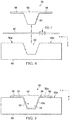
- Figures 4 and 5 illustrate a die set 56 used to stamp form the flat stack 42 into a straight stiffener 30a having a desired cross-sectional shape, which in the illustrated example is a hat shape.
- the die set 56 comprises matching male and female dies 58, 60 respectively, that are placed in a press (not shown) or other machine which forces the dies 58, 60 together.
- the male die 58 includes a punch 64 and a pair of die flanges 66.
- the female die 60 includes a die cavity 62 having a cross sectional shape that matches that of the punch 64.
- the flat stack 42 is placed on upper surfaces 60a of the female die 60.
- the die set 56 is closed causing the punch 64 to force a portion of the flat stack 42 into the die cavity 62, while the die flanges 66 compress other portions of the stack 42 against the upper surfaces 60a of the female die 60.
- Figures 6 and 7 illustrate a cure tool 65 that is used to form the straight stiffener 30a to a desired contour along its length, and maintain the shape of the fully formed stiffener 30 during curing.
- the cure tool 65 is provided with contoured tool surfaces 69 that match the shape of the contoured stiffener 30 shown in Figure 1 .
- the straight stiffener 30a is placed on the cure tool 65, and the assembly of the stiffener 30a and cure tool 65 is then vacuum bagged (not shown) and placed in an autoclave (not shown).
- the combination of heat and pressure P applied to the stiffener 30a in the autoclave form it down onto the contoured tool surfaces 69 and cure the stiffener 30.
- thermoset part 30 is formed of part 30 in the illustrated embodiment, other processes, including a single stage process may be employed in which all contours, both longitudinal and traverse, are formed of a single forming operation.
- the plastic matrix is a thermoplastic
- the flat stack can be heated to forming temperature and stamped formed to final shape in a consolidation press.
- thermal curing may be used where the plastic matrix is a thermoset, other curing methods may be employed, depending upon the particular material system being used, including but not limited to curing the formed thermoset part 30 at room temperature.
- Figure 8 illustrates several unidirectional plies 44a-44e of the stiffener 30 which comprises a balanced laminate that is devoid of 0° plies.
- the plies 44a-44e have fiber angles relative to the major axis of loading 40, of ⁇ 1 , ⁇ 2 and ⁇ 3 , where
- Plies 44a-44e are termed "off-angle" plies because the fibers 48 in these plies form angles with respect to the major axis of loading 40.
- + ⁇ 1 is within the ranges of approximately +5° up to approximately +30°
- - ⁇ 1 is within the ranges of approximately -5° up to approximately - 30°.
- the fibers 48 having orientations of ⁇ 1 provide the laminate stiffener 30 with primary axial or longitudinal stiffness
- the fibers 48 having ⁇ 2 fiber orientations provide the laminate with a lesser amount of axial stiffness, and some degree of transverse stiffness.
- primary axial stiffness means that the fibers 48 in the ply 44 primarily provide the part 30 with longitudinal or axial stiffness, rather than with traverse stiffness.
- Figures 9 and 10 illustrate the off-angle orientation of one of the fibers 48 providing the stiffener 30 with primary axial stiffness.
- the fiber 48 may form part of the ply 44 shown in Figure 8 that has an off-angle fiber orientation of + ⁇ 1 .
- the fiber 48 has a length L' that is less than the length L ( Figure 1 ) of the stiffener 30, and is thus shorter in length than fibers in a 0° ply (not shown) of a conventional laminate which would otherwise extend the entire length L of the stiffener 30.
- buckling 49 of the fiber 48 during forming of the straight stiffener 30a to a longitudinal contour is a function of the longitudinal strain ⁇ x on the fiber 48, the length L' over which the strain ⁇ x is applied and boundary conditions affecting the fiber 48.
- the tendency of the fiber 48 to buckle 49 can be reduced by reducing the longitudinal strain ⁇ x on the fiber 48.
- off-angle plies 44 are less likely to wrinkle than 0° plies when the straight stiffener 30a ( Figure 7 ) is formed to the desired longitudinal contour.
- the use of off-angle plies 44 reduces ply wrinkling for several reasons.
- off-angle plies 44 reduce the length L over which the individual fibers 48 are compressed 57 ( figures 9 and 9A ) during forming, and convert a portion of the stretching ( ⁇ x ) into shear deformation 53 ( Figure 9A ).
- the off-angle plies 44 are allowed to relax 59 to some degree during forming because the fibers 48 having orientation angles of ⁇ 1 that provide the primary axial stiffness transition from a compressive state 57 at the caps 36 to a neutral state 61 at the webs 38, and then to a tensile state 63 at the flanges 34.
- This relaxation 59 of a portion of the length L of the fibers 48 reduces their tendency to buckle 49 during the forming process.
- the off-angle fibers 48 are shorter in length L (than 0° fibers), some degree of transverse slip 55 between the plies 44 ( Figure 9A ) takes place during forming, and this ply slippage resulting in a reduction of the compression 57 of the fibers 48.
- a laminate part 30 may be produced without the need for 0° plies which provides essentially the same stiffness and performance as an equivalent laminate of comparable weight that relies on 0° plies for axial stiffness.
- an existing stiffener design uses 0° plies may be redesigned using off-angle plies 44 in order to reduce ply wrinkling without sacrificing laminate stiffness or increasing the weight of the part 30.
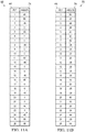
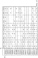
- FIG. 11A and 11B respectively show two possible layup sequences 68, 70 for a contoured laminate part, wherein the ply orientation angles 74 are shown for each of the plies 44 in the layup sequence.
- Figure 11A shows the sequencing of a 26 ply laminate part using a traditional combination of 0°, ⁇ 45° and 90° plies.
- Figure 11B shows a redesigned sequencing of the same 26 ply laminate part having the same laminate thickness which avoids the use of 0° plies in order to reduce ply wrinkling during forming.
- the layup sequence shown in Figure 11B uses a combination of ⁇ 20°, ⁇ 29°, ⁇ 64° and 90° plies, and results in a contoured laminate part that exhibits stiffness equivalent to the laminate part produced using the ply sequence shown in Figure 11A , and without increasing part weight.
- a contoured composite laminate part 30 may have different stiffness requirements in different areas of the part.
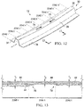
- the contoured composite stiffener 30 may have differing stiffness requirements in different zones 72 along its length. Different stiffness properties in the different zones 72 may be achieved by varying the ply orientations, and/or varying the number of plies of a given orientation in each of the zones 72.
- the stiffener 30 may have a thickness T 3 in zone 6 that is greater than the thickness T 2 in zone 5 but less than the thickness T 1 zone 4.
- Ply ramps 76 are used to transition between zones have differing thicknesses T.
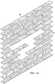
- a laminate part 30 having differing thicknesses along its length to provide individual zones of tailored stiffness properties may be achieved by laying up a combination of full plies 44' and partial plies 44" ( Figure 14 ) of selected fiber orientations in a predetermined sequence.
- Figure 15 illustrates the layup sequence for producing differing stiffnesses in each of zone 1-10.
- the laminate part 30 has differing ply thicknesses T ( Figure 13 ) in various ones of the zones 1-10 based on whether a full ply 44' or partial ply 44" ( Figure 14 ) stretches ( ⁇ x ) over that zone.
- the laminate part 30 represented by the layup sequence shown in Figures 14 and 15 includes a combination of full and partial plies having angular orientations of ⁇ 20°, ⁇ 54°, and 90° cross plies.
- the ⁇ 20° off-angle plies provide the primary axial stiffness.
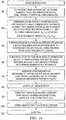
- Figure 16 broadly illustrates the overall steps of one method for producing a contoured composite laminate part 30 having reduced wrinkling and exhibiting differing stiffnesses along its length.
- the method is used to produce an existing part design that utilizes 0° plies with a new part design that avoids the use of 0° plies.
- the shapes of the plies are selected and optimized only after the ply orientations (fiber angles) and the number of plies per angle are determined for each zone 72 having particular stiffness requirements.
- an existing part 30 to be replaced is selected which has part specifications that are required to be met including but not limited to differing stiffness properties along its length.
- information is extracted from the existing part design such as, without limitation, the number of plies per orientation in each zone, material properties and zone dimensions.
- continuous ply thickness values t i j are determined for various ply angle combinations that match the existing part laminate stiffness and thickness.
- the determination made at 88 includes selecting the number of new fiber orientations ⁇ used for the part 30a, which may include, for example, limiting the laminate to a selected number of fiber orientations, such as three fiber orientations ⁇ 1 , ⁇ 2 , ⁇ 3 , between 90° and 0°, wherein 0 ⁇ ⁇ 1 ⁇ ⁇ 2 ⁇ ⁇ 3 ⁇ 90.
- Limiting the number of fiber orientations to a relatively small number, such as three fiber orientations ⁇ 1 , ⁇ 2 , ⁇ 3 allows a full design space to be investigated by iterating over all possible combinations of ⁇ 1 , ⁇ 2 , ⁇ 3 . In practice, fiber orientations are limited to integer numbers between 0 and 90°.
- the process of determining the continuous ply thickness values in step 88 comprises selecting, from multiple possible combinations of fiber angles, a set of fiber angles and determining, for each of the zones, the thickness of the laminate within that zone that will provide the desired stiffness properties.
- the continuous solution is reduced to a solution with a discrete value or integer number of plies 44 that, based on the set of fiber angles selected from the possible combinations of angles, provides the desired stiffness within a zone.
- the ply thickness values T are refined by performing discrete ply thickness integer optimization.
- the discrete ply thickness integer optimization process is a mixed integer optimization problem with an objective of minimizing the difference between the resulting and optimum lamination parameters.
- the process performed at step 90 comprises calculating the number of plies 44 with discrete ply thicknesses for layups in all of the zones 72, thereby ensuring balance and nonzero ply counts.
- the completion of steps 88 and 90 results in multiple possible combinations of sets of fiber angles and ply thicknesses that may provide the desired stiffnesses in each zone. These possible combinations are subsequently refined and filtered in order to optimize lamination properties for each of the zones.
- the results of the ply thickness integer optimization performed at step 90 are filtered.
- Filtering the results at 92 determines the integer number of plies that will optimize the desired in-plane laminate properties, and results in multiple possible solutions.
- This filtering the results of step 90 i.e. the optimization process, involves filtering a number of possible optimized solutions based on an allowed deviation of effective laminate properties from a desired set of laminate properties, and results in multiple candidate fiber angle combinations and ply counts for each of the angle in each of the layup zones 1-10 ( Figure 12 ) of the part 30a.
- This filtering process results in the selection of a laminate design that best reduces wrinkles, matches given laminate stiffness, and minimizes the number of ply sequences.
- Steps 88, 90 and 92 result in multiple candidate fiber angle combinations and ply counts for each of these angles for each of the layup zones.
- layup information is generated, which may include determining the ply shapes and a stacking sequence that conform to a desired set of stacking sequence and manufacturability rules. Stacking sequence rules avoid undesirable laminate modes. The stacking sequence is chosen, at least in part to achieve substantially homogeneous bending stiffness properties in the laminate. When ply spices are required, naturally created splices are preferred which can be achieved by overlapping the ends of medium length plies. The use of natural splices improves layup efficiency by avoiding the need for short plies required to reinforce splices between long plies, while maintaining structural integrity.
- the plies should be continuous wherever possible in order to maximize the transfer loads from one zone to another, as well as to optimize layup efficiency.
- the flat stack of plies 44 is laid up based on the layup information generated at 94.
- the flat stack 42 is formed, as by stamp forming, into a straight part 30 having a desired cross-sectional shape, such a hat or other shape.
- the laminate part 30a is then formed to a desired contour along its major axis of loading. Finally, at 102 the fully formed laminate part 30a is cured.
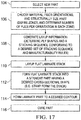
- Figure 17 broadly illustrates the steps of a method of producing a composite laminate part 30 of a new, rather than an existing design.
- the process for producing a newly designed laminate part 30 with reduced wrinkling is similar to that previously described with reference to Figure 16 but without the need for matching the stiffness of an existing part. Briefly, a determination is made of how many plies of each selected ply orientation are required to satisfy specifications for the new part, followed by an optimization of the ply shapes and stacking sequence.
- a new part is selected at 104, and at 106 the material, fiber orientations and structural size of the part are chosen.
- the zones 72 of the part 30 are defined, and the number of plies per orientation in each zone is determined.
- layup information is generated, which comprises determining the ply shapes and a stacking sequence that conforms to a desired set of stacking sequence and manufacturability rules.
- the flat laminate stack is laid up, following which at 112, the flat laminate stack is formed into a straight part having a desired cross-sectional shape, as by stamp forming or other processes previously described.
- laminate part is formed to the desired longitudinal contour and is thereafter cured at 116. As previously mentioned, steps 112 and 114 may be simultaneously performed where the forming is carried out in a single operation.
- Embodiments of the disclosure may find use in a variety of potential applications, particularly in the transportation industry, including for example, aerospace, marine, automotive applications and other application where contoured composite laminate structural members may be used.
- embodiments of the disclosure may be used in the context of an aircraft manufacturing and service method 118 as shown in Figure 18 and an aircraft 120 as shown in Figure 19 .
- Aircraft applications of the disclosed embodiments may include, for example, without limitation, spars, stringers, beams and similar structural members that are contoured along a major axis of loading.
- exemplary method 118 may include specification and design 122 of the aircraft 120 and material procurement 124.
- component and subassembly manufacturing 126 and system integration 128of the aircraft 120 takes place. Thereafter, the aircraft 120 may go through certification and delivery 130 in order to be placed in service 132. While in service by a customer, the aircraft 120 is scheduled for routine maintenance and service 134, which may also include modification, reconfiguration, refurbishment, and so on.
- a system integrator may include without limitation any number of aircraft manufacturers and major system subcontractors; a third party may include without limitation any number of vendors, subcontractors, and suppliers; and an operator may be an airline, leasing company, military entity, service organization, and so on.
- the aircraft 120 produced by exemplary method 118 may include an airframe 136 with a plurality of systems 138 and an interior 1406.
- the airframe 136 may include spars, stringers, beams and similar structural members 142 having one or more contours.
- Examples of high-level systems 138 include one or more of a propulsion system 144 an electrical system 146 a hydraulic system 148 and an environmental system 150. Any number of other systems may be included.
- an aerospace example is shown, the principles of the disclosure may be applied to other industries, such as the marine and automotive industries.
- Systems and methods embodied herein may be employed during any one or more of the stages of the production and service method 118.
- components or subassemblies corresponding to production process 126 may be fabricated or manufactured in a manner similar to components or subassemblies produced while the aircraft 120 is in service.
- one or more apparatus embodiments, method embodiments, or a combination thereof may be utilized during the production stages 126 and 128, for example, by substantially expediting assembly of or reducing the cost of an aircraft 120.
- apparatus embodiments, method embodiments, or a combination thereof may be utilized while the aircraft 120 is in service, for example and without limitation, to maintenance and service 134.
- the phrase "at least one of”, when used with a list of items, means different combinations of one or more of the listed items may be used and only one of each item in the list may be needed.
- “at least one of item A, item B, and item C” may include, without limitation, item A, item A and item B, or item B. This example also may include item A, item B, and item C or item B and item C.
- the item may be a particular object, thing, or a category. In other words, at least one of means any combination items and number of items may be used from the list but not all of the items in the list are required.
Landscapes
- Engineering & Computer Science (AREA)
- Mechanical Engineering (AREA)
- Chemical & Material Sciences (AREA)
- Composite Materials (AREA)
- Physics & Mathematics (AREA)
- Theoretical Computer Science (AREA)
- Evolutionary Computation (AREA)
- Geometry (AREA)
- General Engineering & Computer Science (AREA)
- General Physics & Mathematics (AREA)
- Computer Hardware Design (AREA)
- Textile Engineering (AREA)
- Moulding By Coating Moulds (AREA)
- Manufacture Of Alloys Or Alloy Compounds (AREA)
Abstract
Description
- The present disclosure generally relates to fabrication of contoured composite laminates, especially those having high aspect ratios, and deals more particularly with a method of reducing wrinkling of a laminate during forming to a desired contour.
- In one process for producing elongated composite laminate parts having contoured geometries, unidirectional prepreg plies are laid up, either by hand or using automated layup equipment, to form a flat laminate stack. In an initial forming operation, a pair of matched dies punch form the flat stack into a straight part having a desired cross-sectional shape. In a secondary forming operation, the part is formed onto a contoured forming tool which imparts a desired contour to the part along its length. As a result of these two forming operations, the part has contours along two axes.
- Traditional laminate layups typically use a combination of 0°, 45° and 90° plies. When using these traditional laminates in the process described above to produce contoured composite laminate parts having high aspect ratios, such as stringers and spars used in aerospace vehicles, ply wrinkling may occur because some of the reinforcing fibers in the plies having 0° orientations. The fibers in the 0° plies strain in response to being loaded in compression along the entire length of the part during the secondary forming operation. The problem of ply wrinkling can be more pronounced where the part has a large number of plies and/or contains joggles or aggressive ply ramps along its length. Ply wrinkling is undesirable. In some applications, parts can be reworked to reduce or eliminate ply wrinkling, however the rework adds to labor costs and may reduce production rate. One solution to the wrinkling problem involves cutting the 0° plies into segments however this may decrease load carrying ability. The reduced load carrying ability can be compensated by adding additional plies to the part, however this approach to the problem increases material costs and part weight.
- The disclosure relates in general to fabrication of composite laminate parts having contoured geometries and high aspect ratios, and more specifically to a fabrication method that reduces ply wrinkling during forming of the laminate to a desired contour.
- According to one aspect, a method is provided of making a composite laminate part exhibiting reduced wrinkling which has a desired contour along a major axis of loading. The method includes laying up a substantially flat stack of fiber plies, each having a unidirectional fiber orientation. At least some of the plies provide the part with primary axial stiffness along the major axis of loading. The method includes orienting the plies at off-angles relative to the major axis of loading to reduce the compressive force acting on the fibers during forming. The method also includes forming the stack to a desired cross-sectional shape and forming the stack desired contour. During forming, strain on the plies providing the primary axial stiffness is reduced as a result of their off-angle orientation.
- According to another aspect, a method is provided of making a contoured composite laminate part having a high aspect ratio, a major axis of loading, and a plurality of zones along its length respectively having desired stiffnesses. The method includes selecting a set of fiber angles for plies of unidirectional reinforcing fibers, and determining, for each of the fiber angles, the number of plies in each of the zones required to provide a desired set of in-plane laminate properties in the zone. The method also includes determining the shape and a stacking sequence of the plies. The method further includes laying up plies into a flat stack using the stacking sequence, and forming the flat stack into the shape of the contoured composite laminate part.
- According to still another aspect, a method is provided of making a composite laminate stiffener having a major axis of loading, and contoured both longitudinally and transversely. The method includes laying up a substantially flat stack of fiber plies each having a unidirectional fiber orientation wherein at least some of the plies provide the part with primary axial stiffness along a major axis of loading. Laying up the plies includes orienting the plies providing the primary axial stiffness at off-angles relative to the major axis of loading. The method also includes forming the stack to desired transverse and longitudinal contours, wherein during the forming, the fibers in the plies providing the stiffener with primary axial stiffness transition along their lengths to from compressive state to a neutral state and from the neutral state to a tensile state. During the forming, strain on the plies providing the primary axial stiffness is reduced due to their off-angle orientation.
- According to still another aspect, a method is provided of forming a composite laminate stiffener having a primary axis of loading. The method comprises laying up a flat composite laminate stack of plies of reinforcing fibers, and forming composite laminate stack such that at least some of the plies are subjected to compression loading. The method also includes shortening the length over which the fibers are compressed on the plies that are subjected to compression during forming.
- According to another aspect, a method is provided of forming a composite laminate stiffener contoured along a primary axis of loading. The method includes laying up a flat stack of plies of reinforcing fibers, wherein some of the plies provide the stiffener with primary axial stiffness, and forming the flat stack to a desired contour along the primary axis of loading, wherein the forming places the fibers in the plies providing primary axial stiffness in compression and causes stretching of the fibers. The method also includes reducing the compression of the fibers in the plies providing primary axial stiffness by reducing the length over which the fibers are compressed during the forming. The method also includes converting a portion of the stretching into shear deformation.
- According to a further aspect, a composite laminate stiffener is provided that is contoured along a major axis of loading. The stiffener includes a plurality of laminated plies of unidirectional reinforcing fibers held in a plastic matrix, wherein all of the plies have fiber orientations at off-angles relative to the major axis of loading.
- One of the advantages of the fabrication method is the elimination of plies having 0° fiber orientations which have a tendency to wrinkle when formed to a contoured geometry.
- Another advantage of the fabrication method is that the plies having fiber orientations primarily intended to provide strength and stiffness along the longitudinal axis of the part are shorter in length, compared to 0° fibers which extend entire length of the laminate, and permit increased axial strain before being subject to buckling. The reduction in the length of these fibers reduces the amount of friction between the plies, allowing transverse slip to take place between them, which in turn reduces the compression of those fibers having the highest tendency to buckle.
- A further advantage of the fabrication method is that composite laminate parts with having contoured geometries and high aspect ratios can be produced in which the plies having fiber orientations providing strength and stiffness along the longitudinal axis of the part are oriented such that they transition from a compressive state to a neutral and then a tensile state during forming, permitting these plies to relax rather than buckle.
- Still another advantage of the embodiments is that a highly contoured composite laminate part, such as a contoured stiffener, can be produced that provides adequate stiffness along a major axis of loading without the need for plies having a 0° orientation and without increasing the weight of the part.
- The features, functions, and advantages can be achieved independently in various embodiments of the present disclosure or may be combined in yet other embodiments in which further details can be seen with reference to the following description and drawings.
- The novel features believed characteristic of the illustrative embodiments are set forth in the appended claims. The illustrative embodiments, however, as well as a preferred mode of use, further objectives and advantages thereof, will best be understood by reference to the following detailed description of an illustrative embodiment of the present disclosure when read in conjunction with the accompanying drawings, wherein:
-
Figure 1 is an illustration of a perspective view of a contoured composite laminate stiffener. -
Figure 2 is an illustration of a perspective view of a flat stack of composite plies used to form the stiffener shown inFigure 1 . -
Figure 3 is an illustration of the area designated as "FIG. 3 " inFigure 2 . -
Figure 4 is an illustration of an exploded end view of a die set used to stamp form the flat stack ofFigure 2 into a straight stiffener with a desired cross-sectional shape. -
Figure 5 is an illustration similar toFigure 4 but showing the flat stack having been stamped formed to the desired cross-sectional shape. -
Figure 6 is an illustration of an end view of a cure tool on which the stamped formed stiffener has been placed in preparation for forming it to a desired contour. -
Figure 7 is an illustration of a side view of the cure tool shown inFigure 6 , better illustrating the contoured tool surfaces onto which the straight stiffener are formed to the desired contour. -
Figure 8 is an illustration of an exploded view of several of the plies of the stack shown inFigure 2 . -
Figure 9 is an illustration of a fragmentary, perspective view of the stiffener ofFigure 1 , showing the orientation of a single fiber of one of the off-angle plies. -
Figures 9 is an illustration showing exaggerated buckling of the off-angle fiber and slippage between the plies. -
Figure 9A is an illustration of a perspective view of two adjacent plies of the stiffener ofFigure 9 , also showing exaggerated buckling of the off-angle fiber and slippage between the plies. -
Figure 10 is an illustration similar toFigure 10 but showing a plan view of stiffener. -
Figure 11A and Figure 11B are illustrations of comparative tables showing ply stacking sequences that result in substantially equivalent in-plane stiffness properties, respectively for two laminate parts. -
Figure 12 is an illustration of a perspective view of a contoured composite laminate stiffener having stiffness properties tailored within zones along the length of the stiffener. -
Figure 13 is an illustration of a side view of one of the flanges of the stiffener shown inFigure 13 , viewed in the direction designated as "FIG. 13 " inFigure 12 . -
Figure 14 is an illustration of an exploded, perspective view of a ply stack and stacking sequence that includes partial and full plies. -
Figure 15 is an illustration of a table showing the layup sequence for the ply stack shown inFigure 15 . -
Figure 16 is an illustration of a flow diagram of a method of making an existing design of a contoured composite laminate part with reduced wrinkling. -
Figure 17 is an illustration of a flow diagram of a method of making a new design of a contoured composite laminate part with reduced wrinkling. -
Figure 18 is an illustration of a flow diagram of aircraft production and service methodology. -
Figure 19 is an illustration of a block diagram of an aircraft. - Referring first to
Figure 1 , acomposite laminate part 30 is contoured along its length L and has a radius of curvature R. In the illustrated example, thepart 30 is astringer 30, also referred to herein as astiffener 30, used to transmit loads in a structure such as the airframe of an aircraft, however principles of the disclosed embodiments may be used in the fabrication of a wide range of other types of contoured composite parts, especially structural stiffeners, having various cross sectional shapes. As used herein "contour" and "contoured" are each used in its broadest sense, and includes but is not limited to curvatures in any portion, or throughout the length of thepart 30. "Contour" and "contoured" also include curvatures or other geometric features having either a constant or a changing radius of curvature, as well as local changes in geometry such as, without limitation, joggles. Thestiffener 30 has ahat section 32 defined by acap 36 and a pair ofwebs 38. Thewebs 38 connect thecap 36 with a pair offlanges 34 that extend outwardly. Thestiffener 30 has a length L that is significantly greater than its width W, and thus has a high aspect ratio. - The
stiffener 30 has a major axis of loading 40, which in the illustrated example, is aligned with the X axis in the coordinate system shown at 54. Thestiffener 30 thus possesses double contour. The first contour is along the length of thestiffener 30 in the XZ plane, and the second contour defined by thehat section 32 is in the YZ plane. While ahat stringer 30 is illustrated, principles of the disclosed embodiments are also applicable to other types of stiffeners, including but not limited to stiffeners having other cross-sectional shapes such as a Z-shape, a C-shape, a rounded hat shape, or a blade (an I-shape), etc. Principles of the disclosed embodiments are likewise applicable to other types of composite laminate structural members such as spars and floor beams that are contoured in one or more planes and/or have cross-sectional shapes that vary along the length of the member. - Referring now to
Figures 2 and 3 , thestiffener 30 shown inFigure 1 is fabricated by forming aflat stack 42 of composite plies 44 into a desired cross sectional shape and longitudinal contour. Theplies 44 each comprisingunidirectional fibers 48 held in asuitable plastic matrix 50. Thefibers 48 may be any material suitable for the application including, but not limited to carbon, glass, aramids, ceramic or any combination thereof. Theplastic matrix 50 may be a thermoset or a thermoplastic, or a hybrid material system that includes both a thermoset and a thermoplastic. In the illustrated example, prepreg plies are laid up to form thestack 42, however principles of the embodiments are also applicable to the layup of a stack of dry fibers which are subsequently infused with theplastic matrix 50. - The
ply 44 shown inFigure 2 is a full, continuous ply, however theflat stack 42 may include partial, or discontinuous plies (not shown). Thefibers 48 in each of theplies 44 are oriented at various angles θ relative to the major axis of loading 40, as will be discussed later in more detail. In the illustrated example, theplies 44 comprising theflat stack 42 are balanced. In astack 42 with balanced pairs of fiber angles, theplies 44 are arranged in pairs of equal positive and negative angular orientations. In other examples, however theplies 44 may be unbalanced. Further, theflat stack 42 may be symmetric or unsymmetric. In asymmetric stack 42, the sequence of the plies on either side of a mid-plane 46 of thestack 42 are mirror images of each other. As will be discussed below, all of theplies 44 are oriented at off-angles θ relative to the major axis of loading 40, thus, none of thefibers 48 have 0° fiber orientations. - Attention is now directed to
Figures 4 and 5 which illustrate a die set 56 used to stamp form theflat stack 42 into astraight stiffener 30a having a desired cross-sectional shape, which in the illustrated example is a hat shape. The die set 56 comprises matching male and female dies 58, 60 respectively, that are placed in a press (not shown) or other machine which forces the dies 58, 60 together. The male die 58 includes apunch 64 and a pair ofdie flanges 66. The female die 60 includes adie cavity 62 having a cross sectional shape that matches that of thepunch 64. In preparation for forming operation, theflat stack 42 is placed onupper surfaces 60a of thefemale die 60. Then, as shown inFigure 5 , the die set 56 is closed causing thepunch 64 to force a portion of theflat stack 42 into thedie cavity 62, while thedie flanges 66 compress other portions of thestack 42 against theupper surfaces 60a of thefemale die 60. -
Figures 6 and 7 illustrate acure tool 65 that is used to form thestraight stiffener 30a to a desired contour along its length, and maintain the shape of the fully formedstiffener 30 during curing. Thecure tool 65 is provided with contoured tool surfaces 69 that match the shape of the contouredstiffener 30 shown inFigure 1 . In preparation for contour forming, thestraight stiffener 30a is placed on thecure tool 65, and the assembly of thestiffener 30a andcure tool 65 is then vacuum bagged (not shown) and placed in an autoclave (not shown). The combination of heat and pressure P applied to thestiffener 30a in the autoclave, form it down onto the contoured tool surfaces 69 and cure thestiffener 30. - It should be noted here that while a two-stage process for forming the
part 30 has been described in the illustrated embodiment, other processes, including a single stage process may be employed in which all contours, both longitudinal and traverse, are formed of a single forming operation. For example, where the plastic matrix is a thermoplastic, the flat stack can be heated to forming temperature and stamped formed to final shape in a consolidation press. Moreover, while thermal curing may be used where the plastic matrix is a thermoset, other curing methods may be employed, depending upon the particular material system being used, including but not limited to curing the formedthermoset part 30 at room temperature. -
Figure 8 illustrates severalunidirectional plies 44a-44e of thestiffener 30 which comprises a balanced laminate that is devoid of 0° plies. In this example, theplies 44a-44e have fiber angles relative to the major axis of loading 40, of ±θ1, ±θ2 and ±θ3, where - 0 < θ1 < θ2 ≤ θ3 ≤ 90°,
- θ2 - θ1 ≤ 45°, and
- θ3 - θ2 ≤ 45°.
-
Plies 44a-44e are termed "off-angle" plies because thefibers 48 in these plies form angles with respect to the major axis of loading 40. +θ1 is within the ranges of approximately +5° up to approximately +30°, and -θ1 is within the ranges of approximately -5° up to approximately - 30°. Thefibers 48 having orientations of ±θ1 provide thelaminate stiffener 30 with primary axial or longitudinal stiffness, while thefibers 48 having ±θ2 fiber orientations provide the laminate with a lesser amount of axial stiffness, and some degree of transverse stiffness. As used herein, "primary axial stiffness" means that thefibers 48 in theply 44 primarily provide thepart 30 with longitudinal or axial stiffness, rather than with traverse stiffness. In the illustrated example, the plies having a 90° orientation (θ3 = 90°) provide thestiffener 30 with transverse stiffness. - Attention is now directed to
Figures 9 and 10 which illustrate the off-angle orientation of one of thefibers 48 providing thestiffener 30 with primary axial stiffness. Thefiber 48 may form part of theply 44 shown inFigure 8 that has an off-angle fiber orientation of +θ1. As shown inFigure 10 , thefiber 48 has a length L' that is less than the length L (Figure 1 ) of thestiffener 30, and is thus shorter in length than fibers in a 0° ply (not shown) of a conventional laminate which would otherwise extend the entire length L of thestiffener 30. Referring now also toFigure 9A , buckling 49 of thefiber 48 during forming of thestraight stiffener 30a to a longitudinal contour is a function of the longitudinal strain εx on thefiber 48, the length L' over which the strain εx is applied and boundary conditions affecting thefiber 48. The tendency of thefiber 48 to buckle 49 can be reduced by reducing the longitudinal strain εx on thefiber 48. Reducing the length L' of thefiber 48, allowing the plies and thus thefiber 48, to slip 55 in plane and placing thefiber 48 inshear 53 due to in-plane twisting during forming, all contribute to reducing the longitudinal strain εx on thefiber 48, and thus the potential for buckling 49. - As will be discussed below, off-angle plies 44 are less likely to wrinkle than 0° plies when the
straight stiffener 30a (Figure 7 ) is formed to the desired longitudinal contour. The use of off-angle plies 44 reduces ply wrinkling for several reasons. First, off-angle plies 44 reduce the length L over which theindividual fibers 48 are compressed 57 (figures 9 and 9A ) during forming, and convert a portion of the stretching (εx) into shear deformation 53 (Figure 9A ). Second, the off-angle plies 44 are allowed to relax 59 to some degree during forming because thefibers 48 having orientation angles of ±θ1 that provide the primary axial stiffness transition from acompressive state 57 at thecaps 36 to aneutral state 61 at thewebs 38, and then to atensile state 63 at theflanges 34. Thisrelaxation 59 of a portion of the length L of thefibers 48 reduces their tendency to buckle 49 during the forming process. Third, because the off-angle fibers 48 are shorter in length L (than 0° fibers), some degree oftransverse slip 55 between the plies 44 (Figure 9A ) takes place during forming, and this ply slippage resulting in a reduction of thecompression 57 of thefibers 48. Fourth, due to the lower loading on thefibers 48 in the off-angle plies 44, the strain εfiber on the off-angle fibers 48 is reduced according to εfiber = εx*COS2(θ), where θ is the angular orientation offiber 48 relative to the major axis of loading 40, and εx is the strain of aply 44 in the longitudinal direction 40 (Figure 1 ). - Using plies 44 with selected combinations of off-angle orientations, and preselected ply sequences, a
laminate part 30 may be produced without the need for 0° plies which provides essentially the same stiffness and performance as an equivalent laminate of comparable weight that relies on 0° plies for axial stiffness. Thus, an existing stiffener design uses 0° plies may be redesigned using off-angle plies 44 in order to reduce ply wrinkling without sacrificing laminate stiffness or increasing the weight of thepart 30. - Reference is now made to 11A and 11B which respectively show two
possible layup sequences plies 44 in the layup sequence.Figure 11A shows the sequencing of a 26 ply laminate part using a traditional combination of 0°, ±45° and 90° plies.Figure 11B shows a redesigned sequencing of the same 26 ply laminate part having the same laminate thickness which avoids the use of 0° plies in order to reduce ply wrinkling during forming. The layup sequence shown inFigure 11B uses a combination of ±20°, ±29°, ±64° and 90° plies, and results in a contoured laminate part that exhibits stiffness equivalent to the laminate part produced using the ply sequence shown inFigure 11A , and without increasing part weight. - In some applications, a contoured
composite laminate part 30 may have different stiffness requirements in different areas of the part. For example, referring now toFigures 12 and 13 , the contouredcomposite stiffener 30 may have differing stiffness requirements indifferent zones 72 along its length. Different stiffness properties in thedifferent zones 72 may be achieved by varying the ply orientations, and/or varying the number of plies of a given orientation in each of thezones 72. For example, referring toFigure 13 , thestiffener 30 may have a thickness T3 inzone 6 that is greater than the thickness T2 inzone 5 but less than the thickness T1 zone 4. Ply ramps 76 are used to transition between zones have differing thicknesses T. - Referring also now to
Figures 14 and15 , alaminate part 30 having differing thicknesses along its length to provide individual zones of tailored stiffness properties may be achieved by laying up a combination of full plies 44' andpartial plies 44" (Figure 14 ) of selected fiber orientations in a predetermined sequence.Figure 15 illustrates the layup sequence for producing differing stiffnesses in each of zone 1-10. In this example, thelaminate part 30 has differing ply thicknesses T (Figure 13 ) in various ones of the zones 1-10 based on whether a full ply 44' orpartial ply 44" (Figure 14 ) stretches (εx) over that zone. Thelaminate part 30 represented by the layup sequence shown inFigures 14 and15 includes a combination of full and partial plies having angular orientations of ±20°, ±54°, and 90° cross plies. In this example, the ±20° off-angle plies provide the primary axial stiffness. -
Figure 16 broadly illustrates the overall steps of one method for producing a contouredcomposite laminate part 30 having reduced wrinkling and exhibiting differing stiffnesses along its length. In this example, the method is used to produce an existing part design that utilizes 0° plies with a new part design that avoids the use of 0° plies. As will be discussed below, the shapes of the plies are selected and optimized only after the ply orientations (fiber angles) and the number of plies per angle are determined for eachzone 72 having particular stiffness requirements. - Beginning at 84, an existing
part 30 to be replaced is selected which has part specifications that are required to be met including but not limited to differing stiffness properties along its length. At 86, information is extracted from the existing part design such as, without limitation, the number of plies per orientation in each zone, material properties and zone dimensions. At 88, continuous ply thickness values ti j are determined for various ply angle combinations that match the existing part laminate stiffness and thickness. The determination made at 88 includes selecting the number of new fiber orientations θ used for thepart 30a, which may include, for example, limiting the laminate to a selected number of fiber orientations, such as three fiber orientations θ1, θ2, θ3, between 90° and 0°, wherein 0 < θ1 < θ2 ≤ θ3 ≤ 90. Limiting the number of fiber orientations to a relatively small number, such as three fiber orientations θ1, θ2, θ3 allows a full design space to be investigated by iterating over all possible combinations of θ1, θ2, θ3. In practice, fiber orientations are limited to integer numbers between 0 and 90°. - From classical lamination theory (CLT), the stiffness properties of a laminate may be expressed as a function of a set of interrelated stiffness parameters. Assuming a balanced laminate, there are two equations defining the lamination parameters and one equation for the total laminate thickness. Selecting a set of three fiber angles therefore results in the following three equations per
layup zone 72, with the three ply thicknesses as unknowns, where the fiber angles are the same for all zones:


- where ti j = continuous ply thickness for angle θi in zone j,
- tply = actual material ply thickness
- θ = fiber angle (ply orientation)
- Vj = in-plane lamination parameters of the original laminate design in zone j
- Nj = the total number of plies in zone j
- The above sets of equations for each zone are independent from the equations for the other zones. Only solutions with positive thickness values for all plies in all of the zones are selected. Only those combinations of three fiber angles that result in the desired laminate properties are selected. At this point in the process, all of these combinations result in the same stiffness, but not all of them can be made, as a practical matter, because the thicknesses typically do not correspond to an integer number. Certain combinations of the fiber angles may be eliminated based on certain composite laminate design rules. For example only fiber angle combinations that meet the following constraints are considered:


step 88 comprises selecting, from multiple possible combinations of fiber angles, a set of fiber angles and determining, for each of the zones, the thickness of the laminate within that zone that will provide the desired stiffness properties. - After a continuous thickness solution is obtained at 88, the continuous solution is reduced to a solution with a discrete value or integer number of
plies 44 that, based on the set of fiber angles selected from the possible combinations of angles, provides the desired stiffness within a zone. Atstep 90, the ply thickness values T are refined by performing discrete ply thickness integer optimization. The discrete ply thickness integer optimization process is a mixed integer optimization problem with an objective of minimizing the difference between the resulting and optimum lamination parameters. The process performed atstep 90 comprises calculating the number ofplies 44 with discrete ply thicknesses for layups in all of thezones 72, thereby ensuring balance and nonzero ply counts. The completion ofsteps - Thus, at 92, the results of the ply thickness integer optimization performed at
step 90 are filtered. Filtering the results at 92 determines the integer number of plies that will optimize the desired in-plane laminate properties, and results in multiple possible solutions. This filtering the results ofstep 90, i.e. the optimization process, involves filtering a number of possible optimized solutions based on an allowed deviation of effective laminate properties from a desired set of laminate properties, and results in multiple candidate fiber angle combinations and ply counts for each of the angle in each of the layup zones 1-10 (Figure 12 ) of thepart 30a. This filtering process results in the selection of a laminate design that best reduces wrinkles, matches given laminate stiffness, and minimizes the number of ply sequences. -
Steps plies 44 is laid up based on the layup information generated at 94. Then, at 98, theflat stack 42 is formed, as by stamp forming, into astraight part 30 having a desired cross-sectional shape, such a hat or other shape. At 100, thelaminate part 30a is then formed to a desired contour along its major axis of loading. Finally, at 102 the fully formedlaminate part 30a is cured. - Attention is now directed to
Figure 17 which broadly illustrates the steps of a method of producing acomposite laminate part 30 of a new, rather than an existing design. The process for producing a newly designedlaminate part 30 with reduced wrinkling is similar to that previously described with reference toFigure 16 but without the need for matching the stiffness of an existing part. Briefly, a determination is made of how many plies of each selected ply orientation are required to satisfy specifications for the new part, followed by an optimization of the ply shapes and stacking sequence. - Thus, referring particularly to
Figure 17 , a new part is selected at 104, and at 106 the material, fiber orientations and structural size of the part are chosen. In performingstep 106, thezones 72 of thepart 30 are defined, and the number of plies per orientation in each zone is determined. Next, at 108, layup information is generated, which comprises determining the ply shapes and a stacking sequence that conforms to a desired set of stacking sequence and manufacturability rules. Then, at 110, the flat laminate stack is laid up, following which at 112, the flat laminate stack is formed into a straight part having a desired cross-sectional shape, as by stamp forming or other processes previously described. At 114, laminate part is formed to the desired longitudinal contour and is thereafter cured at 116. As previously mentioned,steps - Embodiments of the disclosure may find use in a variety of potential applications, particularly in the transportation industry, including for example, aerospace, marine, automotive applications and other application where contoured composite laminate structural members may be used. Thus, referring now to
Figures 18 and 19 , embodiments of the disclosure may be used in the context of an aircraft manufacturing andservice method 118 as shown inFigure 18 and anaircraft 120 as shown inFigure 19 . Aircraft applications of the disclosed embodiments may include, for example, without limitation, spars, stringers, beams and similar structural members that are contoured along a major axis of loading. During pre-production,exemplary method 118 may include specification anddesign 122 of theaircraft 120 andmaterial procurement 124. During production, component andsubassembly manufacturing 126 and system integration 128of theaircraft 120 takes place. Thereafter, theaircraft 120 may go through certification anddelivery 130 in order to be placed inservice 132. While in service by a customer, theaircraft 120 is scheduled for routine maintenance andservice 134, which may also include modification, reconfiguration, refurbishment, and so on. - Each of the processes of
method 118 may be performed or carried out by a system integrator, a third party, and/or an operator (e.g., a customer). For the purposes of this description, a system integrator may include without limitation any number of aircraft manufacturers and major system subcontractors; a third party may include without limitation any number of vendors, subcontractors, and suppliers; and an operator may be an airline, leasing company, military entity, service organization, and so on. - As shown in
Figure 19 , theaircraft 120 produced byexemplary method 118 may include anairframe 136 with a plurality ofsystems 138 and an interior 1406. Theairframe 136 may include spars, stringers, beams and similarstructural members 142 having one or more contours. Examples of high-level systems 138 include one or more of apropulsion system 144 an electrical system 146 ahydraulic system 148 and anenvironmental system 150. Any number of other systems may be included. Although an aerospace example is shown, the principles of the disclosure may be applied to other industries, such as the marine and automotive industries. - Systems and methods embodied herein may be employed during any one or more of the stages of the production and
service method 118. For example, components or subassemblies corresponding toproduction process 126 may be fabricated or manufactured in a manner similar to components or subassemblies produced while theaircraft 120 is in service. Also, one or more apparatus embodiments, method embodiments, or a combination thereof may be utilized during the production stages 126 and 128, for example, by substantially expediting assembly of or reducing the cost of anaircraft 120. Similarly, one or more of apparatus embodiments, method embodiments, or a combination thereof may be utilized while theaircraft 120 is in service, for example and without limitation, to maintenance andservice 134. - As used herein, the phrase "at least one of", when used with a list of items, means different combinations of one or more of the listed items may be used and only one of each item in the list may be needed. For example, "at least one of item A, item B, and item C" may include, without limitation, item A, item A and item B, or item B. This example also may include item A, item B, and item C or item B and item C. The item may be a particular object, thing, or a category. In other words, at least one of means any combination items and number of items may be used from the list but not all of the items in the list are required.
- Thus, the present disclosure of the invention comprises embodiments according to the following paragraphs or clauses:
- A1. A method of making a composite laminate part (30) exhibiting reduced wrinkling, and having a desired contour (R) along a major axis of loading (40):
- laying up a substantially flat stack (42) of fiber plies (44) each having a unidirectional fiber orientation, wherein at least some of the plies (44) provide the part (30) with primary axial stiffness along the major axis of loading (40), including orienting the plies (44) providing the primary axial stiffness at off-angles (±θ1) relative to the major axis of loading (40);
- forming the stack (42) to a desired cross sectional shape; and,
- forming the stack (42) to the desired contour along the major axis of loading (40),
- A2. There is also provided, the method of paragraph A1, wherein the plies (44) providing primary axial stiffness are oriented at off-angles (±θ1) within ranges of approximately +5° to +30°, and approximately -5° to -30°.
- A3. There is also provided, the method of paragraph A1 or A2, wherein laying up the flat stack (42) includes orienting all of the plies (44) in the stack (42) at angles (±θ1, ±θ2, ±θ3) greater than approximately ±5° relative to the major axis of loading (40).
- A4. There is also provided, the method of any of paragraphs A1 to A3, wherein orienting the plies (44) is performed such that that fibers (48) in the plies (44) providing primary axial stiffness transition along their length (L') during the forming of the desired contour from a compressive state (57) to a neutral state (61), and from a neutral state (61) to a tensile state (59).
- A5. There is also provided, the method of any of paragraphs A1 to A4, further comprising:
- calculating thickness values (ti j ) for the plies (44);
- performing discrete ply thickness integer optimization;
- filtering the results of calculating thickness values (ti j ) for the plies (44) and the discrete ply thickness integer optimization; and
- optimizing the shape and stacking sequence of the plies (44).
- B1. A method of making a contoured composite laminate part (30) having a high aspect ratio, a major axis of loading (40) and a plurality of zones (72) along its length (L) respectively having desired stiffnesses, comprising:
- selecting a set of fiber angles (±θ1, ±θ2, ±θ3) for plies (44) of unidirectional reinforcing fibers (48);
- determining, for each of the fiber angles (±θ1, ±θ2, ±θ3), a number of plies (44) in each of the zones (72) required to provide a desired set of in-plane laminate properties in the zone (72);
- determining a shape and stacking sequence of the plies (44);
- laying up the plies (44) into a flat stack (42) using the stacking sequence; and
- forming the flat stack (42) into the shape of the contoured composite laminate part (30).
- B2. There is also provided, the method of paragraph B1, wherein:
- determining the fiber angles (±θ1, ±θ2, ±θ3) includes selecting a plurality of possible combinations of fiber angles, and
- determining a number of plies (44) in each of the zones (72) required to provide a desired set of in-plane laminate properties in the zone (72) is performed for each of the possible combinations of angles (±θ1, ±θ2, ±θ3).
- B3. There is also provided, the method of paragraph B1 or B2, wherein:
- determining the fiber angles (±θ1, ±θ2, ±θ3) includes eliminating certain of the possible combinations of fiber angles (±θ1, ±θ2, ±θ3) using a set of composite laminate design rules.
- B4. There is also provided, the method of any of paragraphs B1 to B3, wherein the set of fiber angles (±θ1, ±θ2, ±θ3) include fiber orientations relative to the major axis of loading of θ1, θ2, θ3, where 0 < θ1 < θ2 ≤ θ3 ≤ 90°.
- B5. There is also provided, the method of any of paragraphs B1 to B4, wherein:
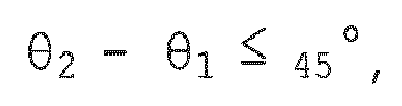

- B6. There is also provided, the method of any of paragraphs B1 to B5, wherein θ1 is selected to be between approximately 5° and 30°.
- B7. There is also provided, the method of any of paragraphs B2 to B6, wherein:
- determining the number of plies (44) in each of the zones (72) includes limiting the number of plies (44) to a discrete value by performing discrete ply thickness integer optimization.
- B8. There is also provided, the method of paragraph B7, wherein determining the number of plies (44) in each of the zones (72) includes filtering the results of the discrete ply thickness integer optimization based on an allowed deviation of effective laminate properties from the desired set of in-plane laminate properties.
- C1. A method of making a composite laminate stiffener (30) having a major axis of loading (40), and contoured both longitudinally and transversely, comprising:
- laying up a substantially flat stack (42) of fiber plies (44) each having a unidirectional fiber orientation (±θ), wherein at least some of the plies (44) provide the stiffener (30) with primary axial stiffness along the major axis of loading (40), including orienting the plies (44) providing the primary axial stiffness at off-angles (±θ) relative to the major axis of loading (40);
- forming the stack (42) to desired transverse and longitudinal contours, wherein during the forming the fibers (48) in plies (44) providing the stiffener (30) with primary axial stiffness transition along their lengths (L') from a compression state (57), to a neutral state (61), and from the neutral state (61) to a tensile state (59); and
- wherein during the forming, strain (εx) on the plies (44) providing the primary axial stiffness is reduced by their off-angle orientation.
- C2. There is also provided, the method of paragraph C1, wherein the off-angle orientations of the plies (44) providing the primary axial stiffness reduces the length (L') to which the fibers (48) of the plies (44) are compressed and causes a portion of the compression is converted to shear deformation (53).
- C3. There is also provided, the method of paragraph C1 or C2, wherein the composite laminate stiffener (30) is a stringer having a hat shape (32) in cross-section, including a cap (36), a pair of webs (30) and a pair of flanges (34), and wherein during forming:
- the fibers (48) in the plies (44) at the cap (36) are in the compression state (57),
- the fibers (48) in the plies (44) in the webs (38) are in the neutral state (61), and
- the fibers (48) in the flanges (34) are in the tensile state (59).
- C4. There is also provided, the method of any of paragraphs C1 to C3, wherein fibers (48) in the plies (44) providing the primary axial stiffness are shorter in length ('L) than the length (L) of the composite laminate stiffener (30) whereby transverse slip (55) between the plies (44) occurs during forming which reduces compression (57) of the fibers (48).
- C5. There is also provided, the method of any of paragraphs C1 to C4, wherein orienting the plies (44) providing the primary axial stiffness at off-angles reduces the compression loading (57) on the fibers (48) in the plies (44) during the forming.
- C6. There is also provided, the method of any of paragraphs C1 to C5, wherein composite laminate stiffener (30) is an existing stiffener design, and the method further comprises:
- determining continuous ply thickness values (ti j ) for various ply angle combinations (±θ1, ±θ2, ±θ3) that match the stiffness and thickness (T) of the existing stiffener design;
- performing discrete ply thickness integer optimization, including calculating a number of plies (40) with discrete ply thicknesses;
- filtering the results of the ply thickness integer optimization, wherein a laminate design is selected that best reduces wrinkles (49) during the forming; and
- generating layup information, including determining ply shapes and the stacking sequence conforming to a desired set of stacking sequence and manufacturability rules.
- C7. There is also provided, the method of paragraphs C1 to C6, wherein the composite laminate stiffener (30) includes a plurality of zones (72) along its length (L) respectively having differing stiffness requirements, and the method further comprises:
- selecting orientations (±θ1, ±θ2, ±θ3) of the plies (44) and a number of plies (44) per orientation (±θ1, ±θ2, ±θ3) for each of the zones (72); and
- then, after selecting the orientations (±θ1, ±θ2, ±θ3) and the number of plies (44) per orientation, selecting shapes of the plies (44) in each of the zones (72).
- D1. A method of forming a composite laminate stiffener (third) having a primary axis of loading (40), comprising:
- laying up a flat composite laminate stack (42) of plies (44) of reinforcing fibers (48);
- forming the composite laminate stack (42) such that the fibers (48) in at least some of the plies (44) are subjected to compression loading (57); and
- shortening a length (L') over which the fibers (48) are compressed (57).
- D2. There is also provided, the method of paragraph D1, wherein the compression loading (57) causes axial strain (εx) in the fibers (48), and the method further comprises:
- reducing the axial strain (εx) in the fibers (48) on those portions of the plies (44) subjected to compression (57) during forming.
- D3. There is also provided, the method paragraph D1 or D2, wherein orienting the fibers (40) is performed such that the reinforcing fibers (48) transition from a compressive state (57) to a neutral state (51), and from a neutral state (61) to a tensile state (59).
- D4. There is also provided, the method of any of paragraphs D1 to D3, further comprising:
- orientating the fibers (48) at angles (±θ1, ±θ2, ±θ3) relative to the primary axis of loading (40) such that friction between plies is reduced which allows slippage (55) between the plies (44).
- D5. There is also provided, the method of any of paragraphs D1 to D4, wherein the angles (±θ1) of the fibers in the plies subjected to compression during forming are between approximately +5° and +30°, and between approximately -5° and -30°.
- E1. A method of forming a composite laminate stiffener (30) contoured along a primary axis of loading (40), comprising:
- laying up a flat stack (42) of plies (44) of reinforcing fibers (48), some of the plies (44) providing the stiffener (30) with primary axial stiffness;
- forming the flat stack (42) to a desired contour along the primary axis of loading (40), wherein the forming places the fibers (48) in the plies (44) providing primary axial stiffness in compression (57) and causes stretching (εx) of the fibers (48);
- reducing the compression (57) of the fibers (48) in the plies (44) providing primary axial stiffness by reducing a length (L') over which the fibers (48) are compressed during the forming; and
- converting a portion of the stretching (εx) into shear deformation (53).
- E2. There is also provided, the method of paragraph E1, wherein reducing the compression (57) of the fibers (48) includes orienting the plies (44) providing primary axial stiffness at off-angles (±θ) relative to the primary axis of loading (40).
- E3. There is also provided, the method of paragraph E1 or E2, wherein reducing the compression (57) includes:
- relaxing the fibers (48) in the plies (44) providing primary axial stiffness such that a portion of the length (L') of the fibers (48) transitions from a compression state (57) to a neutral state (61) and then to a tensile state (59).
- E4. There is also provided, the method of any of paragraphs E1 to E3, wherein reducing the compression (57) includes:
- providing for transverse slip (55) between the plies (44) during the forming.
- E5. There is also provided, the method of any of paragraphs E1 to E4, wherein reducing the compression (57) includes:
- reducing loading on the fibers (48) during the forming to thereby reduce strain (εx) on the fibers (48) in the plies (44) providing primary axial stiffness.
- F1. A composite laminate stiffener (30) contoured along a major axis of loading (40), comprising:
- a plurality of laminated plies (44) of unidirectional reinforcing fibers (48) held in a plastic matrix (50), wherein all of the plies (44) have fiber orientations at off-angles (±θ1, ±θ2, ±θ3) relative to the major axis of loading (40).
- F2. The composite laminate stiffener (30) of paragraph F1, wherein the plies (44) have fiber orientations relative to the major axis of loading of θ1, θ2, θ3, and 0 < θ1 < θ2 ≤ θ3 ≤ 90°.
- F3. The composite laminate stiffener (30) of paragraph F1 or F2, wherein θ1 is between approximately 5° and 30°.
- F4. The composite laminate stiffener (30) of paragraph F1 or F2, wherein the plies (44) have fiber orientations relative to the major axis of loading (40) of -θ1, -θ2, -θ3, and 0 < -θ1 < -θ2 ≤ -θ3 ≤ 90°.
- F5. The composite laminate stiffener (30) of paragraph F1 or F4, wherein -θ1 is between approximately -5° and -30°.
- F6. The composite laminate stiffener (30) of any of paragraphs F1 to F5, wherein the plurality of the plies (44) vary in number along the major axis of loading (40) and define zones (72) along the composite laminate stiffener (30) respectively having different stiffness properties.
- F7. The composite laminate stiffener (30) of any of paragraphs F1 to F6, wherein:
- some of the plies (44) are continuous and other of the plies are discontinuous along the major axis of loading (40), and
- the off-angles (±θ1, ±θ2, ±θ3) include balanced pairs of + and - angles.
- The description of the different illustrative embodiments has been presented for purposes of illustration and description, and is not intended to be exhaustive or limited to the embodiments in the form disclosed. Many modifications and variations will be apparent to those of ordinary skill in the art. Further, different illustrative embodiments may provide different advantages as compared to other illustrative embodiments. The embodiment or embodiments selected are chosen and described in order to best explain the principles of the embodiments, the practical application, and to enable others of ordinary skill in the art to understand the disclosure for various embodiments with various modifications as are suited to the particular use contemplated.
Claims (15)
- A method of making a contoured composite laminate part (30) having a high aspect ratio, a major axis of loading (40) and a plurality of zones (72) along its length (L) respectively having desired stiffnesses, comprising:selecting a set of fiber angles (±θ1, ±θ2, ±θ3) for plies (44) of unidirectional reinforcing fibers (48);determining, for each of the fiber angles (±θ1, ±θ2, ±θ3), a number of plies (44) in each of the zones (72) required to provide a desired set of in-plane laminate properties in the zone (72);determining a shape and stacking sequence of the plies (44) ;laying up the plies (44) into a flat stack (42) using the stacking sequence; andforming the flat stack (42) into the shape of the contoured composite laminate part (30).
- The method of claim 1, wherein:determining the fiber angles (±θ1, ±θ2, ±θ3) includes selecting a plurality of possible combinations of fiber angles, anddetermining a number of plies (44) in each of the zones (72) required to provide a desired set of in-plane laminate properties in the zone (72) is performed for each of the possible combinations of angles (±θ1, ±θ2, ±θ3).
- The method of claim 1 or 2, wherein:determining the fiber angles (±θ1, ±θ2, ±θ3) includes eliminating certain of the possible combinations of fiber angles using a set of composite laminate design rules.
- The method of any of claims 1 to 3, wherein the set of fiber angles include fiber orientations relative to the major axis of loading of θ1, θ2, θ3, where 0 < θ1 < θ2 ≤ θ3 ≤ 90°.
- The method of any of claims 1 to 5, wherein:


- The method of any of claims 1 to 4, wherein θ1 is selected to be between approximately 5° and 30°.
- The method of any of claims 2 to 6, wherein:determining the number of plies (44) in each of the zones (72) includes limiting the number of plies (44) to a discrete value by performing discrete ply thickness integer optimization.
- The method of claim 7, wherein determining the number of plies (44) in each of the zones (72) includes filtering the results of the discrete ply thickness integer optimization based on an allowed deviation of effective laminate properties from the desired set of in-plane laminate properties.
- A composite laminate stiffener (30) contoured along a major axis of loading (40), comprising:a plurality of laminated plies (44) of unidirectional reinforcing fibers (48) held in a plastic matrix (50), wherein all of the plies (44) have fiber orientations at off-angles (±θ1, ±θ2, ±θ3) relative to the major axis of loading (40).
- The composite laminate stiffener (30) of claim 9, wherein the plies (44) have fiber orientations relative to the major axis of loading of θ1, θ2, θ3, and 0 < θ1 < θ2 ≤ θ3 ≤ 90°.
- The composite laminate stiffener (30) of claim 9 or 10, wherein θ1 is between approximately 5° and 30°.
- The composite laminate stiffener (30) of claim 9, wherein the plies (44) have fiber orientations relative to the major axis of loading (40) of -θ1, -θ2, -θ3, and 0 < -θ1 < -θ2 ≤ -θ3 ≤ 90°.
- The composite laminate stiffener of claim 12, wherein - θ1 is between approximately -5° and -30°.
- The composite laminate stiffener (30) of any of claims 9 to 13, wherein the plurality of the plies (44) vary in number along the major axis of loading (40) and define zones (72) along the composite laminate stiffener respectively (30) having different stiffness properties.
- The composite laminate stiffener (30) of any of claims 9 to 14, wherein:some of the plies (44) are continuous and other of the plies are discontinuous along the major axis of loading (40), andthe off-angles (±θ1, ±θ2, ±θ3) include balanced pairs of + and - angles.
Applications Claiming Priority (1)
| Application Number | Priority Date | Filing Date | Title |
|---|---|---|---|
| US15/194,986 US10449754B2 (en) | 2016-06-28 | 2016-06-28 | Wrinkle reduction in formed composite laminates |
Publications (2)
| Publication Number | Publication Date |
|---|---|
| EP3263320A1 true EP3263320A1 (en) | 2018-01-03 |
| EP3263320B1 EP3263320B1 (en) | 2025-02-19 |
Family
ID=58428208
Family Applications (1)
| Application Number | Title | Priority Date | Filing Date |
|---|---|---|---|
| EP17163124.5A Active EP3263320B1 (en) | 2016-06-28 | 2017-03-27 | Wrinkle reduction in formed composite laminates |
Country Status (5)
| Country | Link |
|---|---|
| US (2) | US10449754B2 (en) |
| EP (1) | EP3263320B1 (en) |
| KR (1) | KR102340803B1 (en) |
| ES (1) | ES3024284T3 (en) |
| PT (1) | PT3263320T (en) |
Families Citing this family (11)
| Publication number | Priority date | Publication date | Assignee | Title |
|---|---|---|---|---|
| US11186049B2 (en) | 2018-08-23 | 2021-11-30 | The Boeing Company | Ply splicing for composite charges that are shaped to spanwise contours |
| CN110012238B (en) * | 2019-03-19 | 2021-06-25 | 腾讯音乐娱乐科技(深圳)有限公司 | Multimedia splicing method, device, terminal and storage medium |
| CN110181713A (en) * | 2019-04-24 | 2019-08-30 | 施洋 | A kind of binding resin carries out discarded carbon fibre material to be reprocessed into novel carbon fiber composite and its processing method |
| US11285641B2 (en) * | 2020-02-26 | 2022-03-29 | The Boeing Company | Methods and systems for forming curved composite charges for stringers |
| US11584502B2 (en) | 2020-07-29 | 2023-02-21 | The Boeing Company | Composite fabric hat stringers having interleafed tape plies |
| CN113343445B (en) * | 2021-05-24 | 2022-10-04 | 西南交通大学 | A kind of stability design method of composite sandwich panel |
| JP7779085B2 (en) * | 2021-10-28 | 2025-12-03 | 東レ株式会社 | Composite materials |
| JP7779084B2 (en) * | 2021-10-28 | 2025-12-03 | 東レ株式会社 | Composite materials |
| US12049048B2 (en) | 2022-07-26 | 2024-07-30 | The Boeing Company | Method for high rate production of composite laminate structures |
| US11969953B2 (en) * | 2022-07-26 | 2024-04-30 | The Boeing Company | Prepreg charge optimized for forming contoured composite laminate structures |
| KR102511226B1 (en) | 2022-08-03 | 2023-03-20 | 주식회사 선우하이테크 | Fishing tackle |
Citations (3)
| Publication number | Priority date | Publication date | Assignee | Title |
|---|---|---|---|---|
| US20100121625A1 (en) * | 2008-11-13 | 2010-05-13 | Airbus Operations Limited | Method of designing a composite laminate |
| US7943076B1 (en) * | 2005-05-03 | 2011-05-17 | The Boeing Company | Method of manufacturing curved composite structural elements |
| US20130330503A1 (en) * | 2012-06-08 | 2013-12-12 | The Boeing Company | Optimized Cross-Ply Orientation in Composite Laminates |
Family Cites Families (10)
| Publication number | Priority date | Publication date | Assignee | Title |
|---|---|---|---|---|
| US5064439A (en) * | 1987-01-20 | 1991-11-12 | Richards Medical Company | Orthopedic device of biocompatible polymer with oriented fiber reinforcement |
| US20100012162A1 (en) * | 2001-09-06 | 2010-01-21 | John Cantrell | Pot and pan washing machine |
| US7249943B2 (en) * | 2003-08-01 | 2007-07-31 | Alliant Techsystems Inc. | Apparatus for forming composite stiffeners and reinforcing structures |
| US7243055B2 (en) | 2004-01-28 | 2007-07-10 | The Boeing Company | Composite stacking sequence optimization for multi-zoned composites |
| US8720825B2 (en) | 2005-03-31 | 2014-05-13 | The Boeing Company | Composite stiffeners for aerospace vehicles |
| US9278484B2 (en) | 2008-04-17 | 2016-03-08 | The Boeing Company | Method and apparatus for producing contoured composite structures and structures produced thereby |
| GB201006257D0 (en) | 2010-04-15 | 2010-06-02 | Airbus Operations Ltd | Composite structure |
| JP5130320B2 (en) * | 2010-04-28 | 2013-01-30 | トヨタ自動車株式会社 | Gripping device |
| US8795567B2 (en) | 2010-09-23 | 2014-08-05 | The Boeing Company | Method for fabricating highly contoured composite stiffeners with reduced wrinkling |
| US20160009368A1 (en) | 2013-02-28 | 2016-01-14 | The Boeing Company | Composite laminated plate having reduced crossply angle |
-
2016
- 2016-06-28 US US15/194,986 patent/US10449754B2/en active Active
-
2017
- 2017-03-27 PT PT171631245T patent/PT3263320T/en unknown
- 2017-03-27 ES ES17163124T patent/ES3024284T3/en active Active
- 2017-03-27 EP EP17163124.5A patent/EP3263320B1/en active Active
- 2017-05-22 KR KR1020170062966A patent/KR102340803B1/en active Active
-
2019
- 2019-08-28 US US16/554,333 patent/US20190381780A1/en not_active Abandoned
Patent Citations (3)
| Publication number | Priority date | Publication date | Assignee | Title |
|---|---|---|---|---|
| US7943076B1 (en) * | 2005-05-03 | 2011-05-17 | The Boeing Company | Method of manufacturing curved composite structural elements |
| US20100121625A1 (en) * | 2008-11-13 | 2010-05-13 | Airbus Operations Limited | Method of designing a composite laminate |
| US20130330503A1 (en) * | 2012-06-08 | 2013-12-12 | The Boeing Company | Optimized Cross-Ply Orientation in Composite Laminates |
Also Published As
| Publication number | Publication date |
|---|---|
| US20190381780A1 (en) | 2019-12-19 |
| ES3024284T3 (en) | 2025-06-04 |
| PT3263320T (en) | 2025-03-06 |
| KR20180002017A (en) | 2018-01-05 |
| EP3263320B1 (en) | 2025-02-19 |
| US10449754B2 (en) | 2019-10-22 |
| KR102340803B1 (en) | 2021-12-17 |
| US20170368815A1 (en) | 2017-12-28 |
Similar Documents
| Publication | Publication Date | Title |
|---|---|---|
| EP3263320B1 (en) | Wrinkle reduction in formed composite laminates | |
| EP3162544B1 (en) | Method and device for producing contoured composite laminate stiffeners with reduced wrinkling | |
| KR102022130B1 (en) | Lightweight flexible mandrel and method for making the same | |
| US20200001516A1 (en) | Apparatus for Forming a Contoured Hat Stiffener | |
| EP2561979B1 (en) | Method for forming contoured composite stiffeners | |
| US9242393B2 (en) | Apparatus for fabricating highly contoured composite stiffeners with reduced wrinkling | |
| EP2128019B2 (en) | Modified blade stiffener and fabrication method therefor | |
| EP2303557B1 (en) | Ramped stiffener and apparatus and method for forming the same | |
| US9724891B2 (en) | Bead-stiffened composite parts | |
| EP2185346B1 (en) | Compound contoured composite beams | |
| JP7629060B2 (en) | Splicing of composite structures and method thereof | |
| WO2009111468A1 (en) | Wing and blade structure using pultruded composites | |
| US20130233474A1 (en) | Method of manufacturing a curved profile made of composite material from a rectilinear preform of fiber plies | |
| EP3000586B1 (en) | Method for manufacturing a composite material part comprising a web and at least one flange | |
| US9440401B1 (en) | Method for producing composite laminated parts with non-ruled surfaces | |
| US11806954B2 (en) | Wrinkle mitigation in contoured composite stiffeners | |
| US20220033049A1 (en) | Composite Fabric Hat Stringers having Interleafed Tape Plies | |
| US11987353B2 (en) | Thermoplastic skin panels, torque box and method | |
| US11969953B2 (en) | Prepreg charge optimized for forming contoured composite laminate structures |
Legal Events
| Date | Code | Title | Description |
|---|---|---|---|
| PUAI | Public reference made under article 153(3) epc to a published international application that has entered the european phase |
Free format text: ORIGINAL CODE: 0009012 |
|
| STAA | Information on the status of an ep patent application or granted ep patent |
Free format text: STATUS: REQUEST FOR EXAMINATION WAS MADE |
|
| 17P | Request for examination filed |
Effective date: 20170327 |
|
| AK | Designated contracting states |
Kind code of ref document: A1 Designated state(s): AL AT BE BG CH CY CZ DE DK EE ES FI FR GB GR HR HU IE IS IT LI LT LU LV MC MK MT NL NO PL PT RO RS SE SI SK SM TR |
|
| AX | Request for extension of the european patent |
Extension state: BA ME |
|
| STAA | Information on the status of an ep patent application or granted ep patent |
Free format text: STATUS: EXAMINATION IS IN PROGRESS |
|
| 17Q | First examination report despatched |
Effective date: 20210712 |
|
| RAP3 | Party data changed (applicant data changed or rights of an application transferred) |
Owner name: THE BOEING COMPANY |
|
| GRAP | Despatch of communication of intention to grant a patent |
Free format text: ORIGINAL CODE: EPIDOSNIGR1 |
|
| STAA | Information on the status of an ep patent application or granted ep patent |
Free format text: STATUS: GRANT OF PATENT IS INTENDED |
|
| RIC1 | Information provided on ipc code assigned before grant |
Ipc: B29L 31/00 20060101ALN20240927BHEP Ipc: B32B 7/03 20190101ALI20240927BHEP Ipc: G06F 30/20 20200101ALI20240927BHEP Ipc: B29C 70/20 20060101ALI20240927BHEP Ipc: B29D 99/00 20100101ALI20240927BHEP Ipc: B29C 70/34 20060101AFI20240927BHEP |
|
| INTG | Intention to grant announced |
Effective date: 20241014 |
|
| GRAS | Grant fee paid |
Free format text: ORIGINAL CODE: EPIDOSNIGR3 |
|
| GRAA | (expected) grant |
Free format text: ORIGINAL CODE: 0009210 |
|
| STAA | Information on the status of an ep patent application or granted ep patent |
Free format text: STATUS: THE PATENT HAS BEEN GRANTED |
|
| P01 | Opt-out of the competence of the unified patent court (upc) registered |
Free format text: CASE NUMBER: APP_66889/2024 Effective date: 20241218 |
|
| AK | Designated contracting states |
Kind code of ref document: B1 Designated state(s): AL AT BE BG CH CY CZ DE DK EE ES FI FR GB GR HR HU IE IS IT LI LT LU LV MC MK MT NL NO PL PT RO RS SE SI SK SM TR |
|
| REG | Reference to a national code |
Ref country code: GB Ref legal event code: FG4D |
|
| REG | Reference to a national code |
Ref country code: CH Ref legal event code: EP |
|
| REG | Reference to a national code |
Ref country code: PT Ref legal event code: SC4A Ref document number: 3263320 Country of ref document: PT Date of ref document: 20250306 Kind code of ref document: T Free format text: AVAILABILITY OF NATIONAL TRANSLATION Effective date: 20250226 Ref country code: DE Ref legal event code: R096 Ref document number: 602017087818 Country of ref document: DE |
|
| REG | Reference to a national code |
Ref country code: SE Ref legal event code: TRGR |
|
| REG | Reference to a national code |
Ref country code: IE Ref legal event code: FG4D |
|
| REG | Reference to a national code |
Ref country code: ES Ref legal event code: FG2A Ref document number: 3024284 Country of ref document: ES Kind code of ref document: T3 Effective date: 20250604 |
|
| REG | Reference to a national code |
Ref country code: NL Ref legal event code: MP Effective date: 20250219 |
|
| PG25 | Lapsed in a contracting state [announced via postgrant information from national office to epo] |
Ref country code: RS Free format text: LAPSE BECAUSE OF FAILURE TO SUBMIT A TRANSLATION OF THE DESCRIPTION OR TO PAY THE FEE WITHIN THE PRESCRIBED TIME-LIMIT Effective date: 20250519 |
|
| PG25 | Lapsed in a contracting state [announced via postgrant information from national office to epo] |
Ref country code: FI Free format text: LAPSE BECAUSE OF FAILURE TO SUBMIT A TRANSLATION OF THE DESCRIPTION OR TO PAY THE FEE WITHIN THE PRESCRIBED TIME-LIMIT Effective date: 20250219 |
|
| PG25 | Lapsed in a contracting state [announced via postgrant information from national office to epo] |
Ref country code: PL Free format text: LAPSE BECAUSE OF FAILURE TO SUBMIT A TRANSLATION OF THE DESCRIPTION OR TO PAY THE FEE WITHIN THE PRESCRIBED TIME-LIMIT Effective date: 20250219 |
|
| PGFP | Annual fee paid to national office [announced via postgrant information from national office to epo] |
Ref country code: ES Payment date: 20250401 Year of fee payment: 9 |
|
| REG | Reference to a national code |
Ref country code: LT Ref legal event code: MG9D |
|
| PG25 | Lapsed in a contracting state [announced via postgrant information from national office to epo] |
Ref country code: IS Free format text: LAPSE BECAUSE OF FAILURE TO SUBMIT A TRANSLATION OF THE DESCRIPTION OR TO PAY THE FEE WITHIN THE PRESCRIBED TIME-LIMIT Effective date: 20250619 Ref country code: NO Free format text: LAPSE BECAUSE OF FAILURE TO SUBMIT A TRANSLATION OF THE DESCRIPTION OR TO PAY THE FEE WITHIN THE PRESCRIBED TIME-LIMIT Effective date: 20250519 |
|
| PG25 | Lapsed in a contracting state [announced via postgrant information from national office to epo] |
Ref country code: NL Free format text: LAPSE BECAUSE OF FAILURE TO SUBMIT A TRANSLATION OF THE DESCRIPTION OR TO PAY THE FEE WITHIN THE PRESCRIBED TIME-LIMIT Effective date: 20250219 |
|
| PG25 | Lapsed in a contracting state [announced via postgrant information from national office to epo] |
Ref country code: HR Free format text: LAPSE BECAUSE OF FAILURE TO SUBMIT A TRANSLATION OF THE DESCRIPTION OR TO PAY THE FEE WITHIN THE PRESCRIBED TIME-LIMIT Effective date: 20250219 |
|
| PG25 | Lapsed in a contracting state [announced via postgrant information from national office to epo] |
Ref country code: LV Free format text: LAPSE BECAUSE OF FAILURE TO SUBMIT A TRANSLATION OF THE DESCRIPTION OR TO PAY THE FEE WITHIN THE PRESCRIBED TIME-LIMIT Effective date: 20250219 |
|
| PG25 | Lapsed in a contracting state [announced via postgrant information from national office to epo] |
Ref country code: GR Free format text: LAPSE BECAUSE OF FAILURE TO SUBMIT A TRANSLATION OF THE DESCRIPTION OR TO PAY THE FEE WITHIN THE PRESCRIBED TIME-LIMIT Effective date: 20250520 Ref country code: BG Free format text: LAPSE BECAUSE OF FAILURE TO SUBMIT A TRANSLATION OF THE DESCRIPTION OR TO PAY THE FEE WITHIN THE PRESCRIBED TIME-LIMIT Effective date: 20250219 |
|
| REG | Reference to a national code |
Ref country code: AT Ref legal event code: MK05 Ref document number: 1767912 Country of ref document: AT Kind code of ref document: T Effective date: 20250219 |
|
| PG25 | Lapsed in a contracting state [announced via postgrant information from national office to epo] |
Ref country code: SM Free format text: LAPSE BECAUSE OF FAILURE TO SUBMIT A TRANSLATION OF THE DESCRIPTION OR TO PAY THE FEE WITHIN THE PRESCRIBED TIME-LIMIT Effective date: 20250219 |
|
| PG25 | Lapsed in a contracting state [announced via postgrant information from national office to epo] |
Ref country code: DK Free format text: LAPSE BECAUSE OF FAILURE TO SUBMIT A TRANSLATION OF THE DESCRIPTION OR TO PAY THE FEE WITHIN THE PRESCRIBED TIME-LIMIT Effective date: 20250219 |
|
| PG25 | Lapsed in a contracting state [announced via postgrant information from national office to epo] |
Ref country code: AT Free format text: LAPSE BECAUSE OF FAILURE TO SUBMIT A TRANSLATION OF THE DESCRIPTION OR TO PAY THE FEE WITHIN THE PRESCRIBED TIME-LIMIT Effective date: 20250219 |
|
| PG25 | Lapsed in a contracting state [announced via postgrant information from national office to epo] |
Ref country code: CZ Free format text: LAPSE BECAUSE OF FAILURE TO SUBMIT A TRANSLATION OF THE DESCRIPTION OR TO PAY THE FEE WITHIN THE PRESCRIBED TIME-LIMIT Effective date: 20250219 Ref country code: EE Free format text: LAPSE BECAUSE OF FAILURE TO SUBMIT A TRANSLATION OF THE DESCRIPTION OR TO PAY THE FEE WITHIN THE PRESCRIBED TIME-LIMIT Effective date: 20250219 |
|
| REG | Reference to a national code |
Ref country code: CH Ref legal event code: H13 Free format text: ST27 STATUS EVENT CODE: U-0-0-H10-H13 (AS PROVIDED BY THE NATIONAL OFFICE) Effective date: 20251023 |
|
| PG25 | Lapsed in a contracting state [announced via postgrant information from national office to epo] |
Ref country code: RO Free format text: LAPSE BECAUSE OF FAILURE TO SUBMIT A TRANSLATION OF THE DESCRIPTION OR TO PAY THE FEE WITHIN THE PRESCRIBED TIME-LIMIT Effective date: 20250219 |
|
| PG25 | Lapsed in a contracting state [announced via postgrant information from national office to epo] |
Ref country code: SK Free format text: LAPSE BECAUSE OF FAILURE TO SUBMIT A TRANSLATION OF THE DESCRIPTION OR TO PAY THE FEE WITHIN THE PRESCRIBED TIME-LIMIT Effective date: 20250219 |
|
| PG25 | Lapsed in a contracting state [announced via postgrant information from national office to epo] |
Ref country code: LU Free format text: LAPSE BECAUSE OF NON-PAYMENT OF DUE FEES Effective date: 20250327 |
|
| REG | Reference to a national code |
Ref country code: DE Ref legal event code: R097 Ref document number: 602017087818 Country of ref document: DE |
|
| REG | Reference to a national code |
Ref country code: BE Ref legal event code: MM Effective date: 20250331 |
|
| PG25 | Lapsed in a contracting state [announced via postgrant information from national office to epo] |
Ref country code: MC Free format text: LAPSE BECAUSE OF FAILURE TO SUBMIT A TRANSLATION OF THE DESCRIPTION OR TO PAY THE FEE WITHIN THE PRESCRIBED TIME-LIMIT Effective date: 20250219 |
|
| PLBE | No opposition filed within time limit |
Free format text: ORIGINAL CODE: 0009261 |
|
| STAA | Information on the status of an ep patent application or granted ep patent |
Free format text: STATUS: NO OPPOSITION FILED WITHIN TIME LIMIT |
|
| PG25 | Lapsed in a contracting state [announced via postgrant information from national office to epo] |
Ref country code: BE Free format text: LAPSE BECAUSE OF NON-PAYMENT OF DUE FEES Effective date: 20250331 |
|
| PG25 | Lapsed in a contracting state [announced via postgrant information from national office to epo] |
Ref country code: CH Free format text: LAPSE BECAUSE OF NON-PAYMENT OF DUE FEES Effective date: 20250331 |
|
| PG25 | Lapsed in a contracting state [announced via postgrant information from national office to epo] |
Ref country code: IE Free format text: LAPSE BECAUSE OF NON-PAYMENT OF DUE FEES Effective date: 20250327 |
|
| 26N | No opposition filed |
Effective date: 20251120 |
|
| PGFP | Annual fee paid to national office [announced via postgrant information from national office to epo] |
Ref country code: SE Payment date: 20260327 Year of fee payment: 10 |
|
| PGFP | Annual fee paid to national office [announced via postgrant information from national office to epo] |
Ref country code: GB Payment date: 20260327 Year of fee payment: 10 |
|
| PGFP | Annual fee paid to national office [announced via postgrant information from national office to epo] |
Ref country code: DE Payment date: 20260327 Year of fee payment: 10 |
|
| PGFP | Annual fee paid to national office [announced via postgrant information from national office to epo] |
Ref country code: IT Payment date: 20260319 Year of fee payment: 10 |
|
| PGFP | Annual fee paid to national office [announced via postgrant information from national office to epo] |
Ref country code: FR Payment date: 20260325 Year of fee payment: 10 |
|
| PGFP | Annual fee paid to national office [announced via postgrant information from national office to epo] |
Ref country code: PT Payment date: 20260311 Year of fee payment: 10 |