EP3263235A1 - Device and method for transporting and examining fast-moving objects to be treated - Google Patents
Device and method for transporting and examining fast-moving objects to be treated Download PDFInfo
- Publication number
- EP3263235A1 EP3263235A1 EP17183349.4A EP17183349A EP3263235A1 EP 3263235 A1 EP3263235 A1 EP 3263235A1 EP 17183349 A EP17183349 A EP 17183349A EP 3263235 A1 EP3263235 A1 EP 3263235A1
- Authority
- EP
- European Patent Office
- Prior art keywords
- unit
- control
- bodies
- conveying path
- camera
- Prior art date
- Legal status (The legal status is an assumption and is not a legal conclusion. Google has not performed a legal analysis and makes no representation as to the accuracy of the status listed.)
- Granted
Links
Images
Classifications
-
- B—PERFORMING OPERATIONS; TRANSPORTING
- B07—SEPARATING SOLIDS FROM SOLIDS; SORTING
- B07C—POSTAL SORTING; SORTING INDIVIDUAL ARTICLES, OR BULK MATERIAL FIT TO BE SORTED PIECE-MEAL, e.g. BY PICKING
- B07C5/00—Sorting according to a characteristic or feature of the articles or material being sorted, e.g. by control effected by devices which detect or measure such characteristic or feature; Sorting by manually actuated devices, e.g. switches
- B07C5/34—Sorting according to other particular properties
- B07C5/342—Sorting according to other particular properties according to optical properties, e.g. colour
- B07C5/3422—Sorting according to other particular properties according to optical properties, e.g. colour using video scanning devices, e.g. TV-cameras
-
- B—PERFORMING OPERATIONS; TRANSPORTING
- B07—SEPARATING SOLIDS FROM SOLIDS; SORTING
- B07C—POSTAL SORTING; SORTING INDIVIDUAL ARTICLES, OR BULK MATERIAL FIT TO BE SORTED PIECE-MEAL, e.g. BY PICKING
- B07C5/00—Sorting according to a characteristic or feature of the articles or material being sorted, e.g. by control effected by devices which detect or measure such characteristic or feature; Sorting by manually actuated devices, e.g. switches
- B07C5/34—Sorting according to other particular properties
-
- B—PERFORMING OPERATIONS; TRANSPORTING
- B07—SEPARATING SOLIDS FROM SOLIDS; SORTING
- B07C—POSTAL SORTING; SORTING INDIVIDUAL ARTICLES, OR BULK MATERIAL FIT TO BE SORTED PIECE-MEAL, e.g. BY PICKING
- B07C5/00—Sorting according to a characteristic or feature of the articles or material being sorted, e.g. by control effected by devices which detect or measure such characteristic or feature; Sorting by manually actuated devices, e.g. switches
- B07C5/36—Sorting apparatus characterised by the means used for distribution
- B07C5/363—Sorting apparatus characterised by the means used for distribution by means of air
-
- G—PHYSICS
- G01—MEASURING; TESTING
- G01N—INVESTIGATING OR ANALYSING MATERIALS BY DETERMINING THEIR CHEMICAL OR PHYSICAL PROPERTIES
- G01N21/00—Investigating or analysing materials by the use of optical means, i.e. using sub-millimetre waves, infrared, visible or ultraviolet light
- G01N21/84—Systems specially adapted for particular applications
- G01N21/88—Investigating the presence of flaws or contamination
- G01N21/90—Investigating the presence of flaws or contamination in a container or its contents
- G01N21/909—Investigating the presence of flaws or contamination in a container or its contents in opaque containers or opaque container parts, e.g. cans, tins, caps, labels
Definitions
- the present invention relates to an apparatus and a method for transporting and inspecting high-speed, separated bodies of packaging components and packaging precursors having at least one lateral surface and at least one ceiling surface.
- Such individual bodies of packaging or packaging components, or packaging precursors are, for example, preforms for blow molding, PET bottles, yogurt cups, containers, lids, closures, screw caps or generally cylindrical, closed on one side hollow body, which are often constructed as a multilayer plastic body.
- these bodies have at least one lateral surface and a ceiling surface, wherein the ceiling surface may include an opening.
- They can likewise have a floor surface which is predominantly parallel to the ceiling surface, provided that it is not formed by the lateral surface in the manner of a cone or rounded cone, as is the case, for example, with preforms.
- a separating device for such packaging, or packaging components is from the CH 702 396 A2 known, an investigation device for already isolated objects is from the EP 2 453 225 A2 known. Finally, out of the DE 20 2005 019 111 U1 a belt for a processing machine known to be transported in the bottomless bottles and rotated during transport.
- the present invention proposes the process task of proposing a particularly fast and reliable checking and rejecting step and the device task of proposing a corresponding device.
- the process object is achieved by a method for transporting and inspecting high-speed bodies of packaging components and packaging precursors having at least one lateral surface and at least one ceiling surface, in which an examination unit transported body of the material to be treated are taken from this in a conveying path, the conveying path passes the body of at least one, connected to a control unit, control camera, the control unit based on the originating from the control camera image data detects the error liability of each body and the examination unit to the body a Aussonderü passes, wherein either the examination unit or the Aussonderü ejects the body, in particular approximately in the free throw, and wherein the Aussonder founded changes the trajectories of recognized as faulty bodies and recognized as faultless bodies relative to each other by means of a non-contact power application.
- this method allows a very fast overall process of transport, control and segregation, in particular by the discharge in the litter, especially in approximately free litter.
- the position of the trajectory in space according to the invention is variable within very large limits, according to the invention, the throw angle can be approximately zero, so the trajectory pointing approximately vertically downwards, it can be 45 °, so the trajectory pointing obliquely downward, 90 °, the So be trajectory about straight, but also detect obtuse angles, so the trajectory so obliquely upwards or even show upwards.
- the control unit is the period of time per moving body of the material to be treated, which is between image acquisition and entry into the effective range of Aussondertechnik.
- the invention means contactless all measures that do not require direct mechanical contact between Aussonderü and treated, so for example, the action of electric or magnetic fields or pressure waves. Under control camera, the invention initially understands any type of optical (daylight) cameras, but also IR cameras or other fast-acting imaging systems.
- the invention also includes a control camera any other sensor that detects relevant properties of the body, such as color sensors that detect the presence of a color and their parameters, including sensors that can detect, for example, the dimensional accuracy of the body.
- the latter can be, for example, sensors, strain gauges, contact sensors or the like, which, if the required dimensions are not met, send a corresponding signal to the control unit, which does not necessarily have to be an image but only a pure yes / no signal can be.
- the use of an IR camera, in particular a cooled IR camera is of great advantage, as it enables accurate imaging in the shortest possible sequence, so that processing speeds of more than 2500 body / min are achieved.
- the cooled IR camera requires less than 0.5 ms for a recording, so is no processing bottleneck and allows to control in the visible light not visible structures of the body. Mentioned here are more EVOH layers or the like.
- the invention uses at least one control camera, but four or more control cameras are common, provided that the geometric structure of the body can be sufficiently detected only by a plurality of cameras.
- the control cameras have to be aligned with the part of the body to be observed by them, ie laterally, obliquely or vertically looking, the sequence of viewing directions during the transport of the body is freely selectable, a ground control does not necessarily take place before a side control or even necessarily to be available.
- the separating unit acts directly at the end of the conveying path or at a distance from the end of the conveying path. If the Aussonderü acts according to the invention immediately adjacent to the examination unit, the trajectory is particularly short, since an immediate influence on the trajectory takes place. Due to the very short design of the separation unit achieved in this way, no basically empty time is required for a further transport of the treatment goods to the removal unit, rather the separation takes place immediately after passing through the examination unit. In the other case, the examination unit already ejects the examined objects in the litter whose trajectory leads through the effective range of the litter unit. This then changes the trajectory of the free-flying body as described.
- the spatial separation of examination and secretion unit advantageously allows the interposition of other control cameras or devices that examine previously unexamined areas of the body undisturbed by any holding or guiding organs. This is a good supplement to the investigational devices that have already been used in the area of the examination unit. In free flight, the body surface is accessible without obstruction and thus examined.
- the method according to the invention provides that the rejection unit exerts a force on the bodies by means of non-contact exertion of force.
- the said non-contact exertion of force especially the compressed air surge is preferred. This is ideal due to the shortness of the available time per body of the material to be treated, since this only one valve must be opened and closed. With great advantage moving parts are avoided, which would have to be returned to their original position time-consuming. A mechanical influence on the trajectory by stop or leading edges is avoided with advantage, there can be no abrasion, no jamming or the like.
- compressed air is usually easily available at each installation site of the device, or at each site of the method.
- the conveying path guides the bodies past the at least one control camera, free of floor and / or ceiling, so that they can examine the floor, the top surface or bottom and top surface. This is done in particular by means of a frictional parallel tape run, as will be explained below.
- the conveying path of the examination unit rotates the body during its passage through the examination unit about its longitudinal axis, for example by means of two different fast-moving bands.
- At least one control camera a ground and at least one control camera receives a side surface of the body, in particular the bodies in free flight before sorting out a lateral control by looking to their side control cameras, up to four or more, be subjected, with all control cameras are connected to the control and evaluation.
- the method thus allows the complete surface control of the body to be treated, especially by using more than two sensors / control cameras.
- the control according to the invention by fast daylight cameras just as possible, as by very fast-working cooled IR cameras having exposure times of a few hundred microseconds and detect each individual body of the treated material accurately and accurately. The latter are particularly provided according to the invention, when the body must be controlled to the quality of a non-visible in the visible light barrier.
- the invention does not depend on whether first a bottom or top side and then a side control of the body or vice versa. It is readily according to the invention to detect in the free flight and the bottom or cover side with the sensors when the pages were previously detected. Likewise, it is according to the invention, if in the free flight no more sensors are applied but the surface control is done even before the screening step in the examination unit using there arranged cameras in ceiling, floor and / or side position.
- At least one trajectory past a separating surface of a separating body in particular passes each trajectory on a respective separating surface, wherein both separating surfaces form an angle between them.
- the bodies in free flight are subjected to a lateral control by looking to their side control cameras before sorting out, these sensors are also connected to the control and evaluation unit.
- the sorting then takes place at a later stage of free flight.
- the method according to the invention also detects a second, the first subordinate rejection.
- This very advantageous development allows additional protection against incorrect procedures. Should the first discard step be unsuccessful, for example because the camera, data relay, data processing, compressed air control or the like does not work, then this second discarding step prevents the erroneous release of unchecked or faulted but unrecorded body.
- this second rejection step blocks the trajectory of all bodies and thus prevents even only a faulty packaging part from being let through.
- the Locking can be done without contact, in particular by a blast of compressed air, or touching, for example by moving an arm, a lock or generally a physical body in the trajectory (s) of the body. It is also according to the invention if only the body recognized as defective but not separated out in the first rejection step is discarded.
- the device task is in a device for transporting and inspecting isolated, high-speed bodies of packaging components and packaging precursors having at least one lateral surface and at least one ceiling surface, comprising a) an examination unit, wherein the examination unit at least one control camera and a control unit connected thereto and a transport device wherein the transport device is transporting the bodies of the material to be treated past the at least one control camera, wherein the control unit determines the faultiness of each body on the basis of the image data originating from the at least one control camera; and b) further comprising a removal unit functionally connected to the examination unit, wherein the secretion unit of the examination unit is body receiving, whereby either the examination unit or the secretion unit the K body is throwing out in the free throw, wherein the Aussonderody the trajectories of detected as defective bodies and detected as error-free bodies relative to each other is influencing means of a contactless exertion of force.
- the transport device, the body floor and / or blanket is transported past at least a control camera of the examination unit.
- the transport device may also be designed, at least in part, as an upper guide, that is to say hold the bodies on their cover surface, for example as a vacuum belt.
- the transport device must pass the body quietly in front of the camera, so avoid pendulum movements or inclinations.
- it is formed in front of the camera as an upper guide, it is provided according to the invention to make it wedge-shaped or dovetailed at its end at the camera end. The forms mentioned arise in each case in top or bottom view. This ensures that the body is low on a peripheral position, ie radially outward, last touched, in the second case, the touch is even symmetrical.
- the entire transport device can be designed as an upper guide.
- the said final shape in the area of the transfer to the Aussonderü provided in order to ensure always the same attitude of the body.
- the transport device has two driven and pretensioned belts, each revolving around a drive wheel and a further wheel, which define a conveying path between them.
- a belt transport allows a soft, damage-free guidance of the body under sufficient clamping force, so that the body rotatably guided and a doubt-free recording are possible.
- the distance between the two belts in the conveying path is therefore slightly smaller than the free outer diameter of the body.
- By circulating belts can be achieved structurally simple high transport speeds, for example, 5m / s.
- the inventively provided tape transport also has the advantage of fluctuations in body supply to cope with a certain distance, the body to each other as a turntable or a nest transport is not required.
- the belts of the transport device are revolving at mutually different speeds.
- At least one band is formed as a toothed belt, preferably both bands and / or a wheel as a guide wheel and / or a wheel as the second drive wheel and / or at least one impeller per band is provided.
- frictionally driven belts are not unproblematic in the long run, since the surface can glaze through occasional slipping, so that timing belt with drive gears can be more advantageous.
- the use of smooth strip surfaces according to the invention is by no means excluded.
- one drive and one guide wheel or two drive wheels per band can be provided. Between these, one or more wheels may be arranged so that they lead to a certain bias of the band and prevent its flutter.
- the bands may be biased by a spring force, for example, by the wheels are arranged radially displaceable against a spring force.
- the Aussonderü has a compressed air valve, in particular a compressed air valve with closing and opening times of less than 3.5 ms.
- the device has a separating body for the separation of trajectories with at least one separating surface, in particular with two parting surfaces which enclose an angle between them. This separator prevents backmixing of the already trajectory separated flawless and faulty material to be treated by unintentional disturbances.
- the reliability of the device increases with advantage. Should the first spill unit or even the examination unit fail altogether, the second spill unit completely blocks the trajectory of the bodies and thus prevents the device from releasing defective bodies. The entire device then enters an error mode and must be actively enabled by an operator after the malfunction has been remedied. It is therefore also erfindungsezeß when a subunit is provided in the first secretion unit, which verifies the actually carried out a body. This can be realized, for example, by means of a light barrier to be traversed by the rejected body, a pressure-sensitive field on which the body impacts or the like.
- the first rejection has failed and the described second rejection unit becomes active.
- the second rejection becomes active when a body flies through the photocell, which should have been ejected beforehand.
- the second discard unit also becomes active when, for example, the camera is not delivering pictures or another error is present upstream of the second discard unit and it receives this error.
- the examination unit has a second conveying path in which the bodies are guided on the floor and / or on the ceiling side, this conveying path being guided past at least one control camera looking at the body.
- This second conveying path can be connected directly to the first or arranged in front of it in terms of process technology. In both cases, a transfer area between the two conveying paths is provided. It is important to the invention that a control of the body can be done even before the actual examination unit, especially if this leads to a shorter overall length of the device or is required due to a body required longer processing time period.
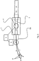
- Fig. 1 shows a sketchy side view of an embodiment of the invention.
- On the right is one Supply device 13 shown, which takes over the material to be treated by a first separating device, not shown, and transfers as a continuous stream of contacting bodies 21 to the examination unit 1 and thereby finally separated, so that the body 21 no longer contact.
- This feeder 13 transports the bodies 21 at a first speed either upright on a belt or suspended on a vacuum belt.
- a second, accelerating transport section can be provided, which accelerates the bodies to a second speed, namely that which prevails in the examination unit 1.
- the bodies are as described packaging or packaging precursors such as preforms, lids, cups or the like more.
- the examination unit 1 has a control camera 4, which is formed in this example as daylight or cooled IR camera. Other imaging sensors as well as other sensors are also as described according to the invention.
- the control camera 4 looks from above or below on the front side of the body 21 of the material to be treated and is operatively and in terms of data connected to a control unit 3.
- This control unit 3 receives data from the camera 4, namely recordings of individual bodies 21 of the material to be treated, and compares these with nominal values.
- the control camera 4 is a daylight camera or, in particular cooled, IR camera. With the latter, the presence, completeness and thickness of an (EVOH) barrier layer in each body can be determined.
- the control unit can also determine the presence and the quality of other layers in the wall material of the body.
- the bodies are transported by the examination unit 1 along a conveying path 2, which passes under / above the visual axis of the camera 4.
- This conveyor may according to the invention have two differently fast moving bands 12, so that the between them guided body 21 during its passage through the examination unit performs a rotation about its longitudinal axis.
- inventively provided laterally looking cameras can record and control the full extent of a body. This applies insofar as the side surface is not covered by the bands.
- a secretion unit 5 is arranged so that it can act on body 21, which have left the examination unit 1.
- the Aussonderritt 5 is provided immediately after the end of the conveying path 2 of the examination unit 1, which ejects the examined body 21 in this example approximately in a straight line.
- the reject unit 5 is formed connected to the control unit 3 and has a valve 18, in particular a closable by means of a valve nozzle whose nozzle opening is directed to the trajectory of the body 21. If the control unit 3 has identified a body 21 as having a fault on the basis of the data of the one or more cameras 4, it sends a control signal to the valve 18 or the nozzle and opens it at a time which is chosen such that one out of the nozzle exiting pressure of compressed air impinges on the body when it enters the effective area 19 of the nozzle of the Aussonderiser 5.
- the control unit thus calculates on the basis of the distance between effective range 19 and camera 4, the distance between the nozzle opening and effective range 19, the opening and closing times of the valve, the transport speed of the body and its time of flight to the effective range 19 that time at which the valve is opened must, so that the pressure surge can affect the body 21 in its trajectory.
- the trajectory 6 of the faulty then differs from the trajectory 7 of the faultless body so that the safe separation of the body is guaranteed.
- a separating body 9 is arranged, which here has two separating surfaces 8.
- Fig. 1 two positions for one or more additional cameras 10 are drawn, which consider the side or lateral surfaces of the body undisturbed in the open air. These two positions are after or in front of the position of the first camera 4.
- the side camera (s) 10 may be arranged so that they observe the body in flight and thus between effective range 19 of the Aussonderiser 5 and the end of the conveying path 2 of Examination unit 1 may be arranged.
- the side camera (s) 10 are effectively arranged in the area between the beginning of the conveying path 2 and the end of the feeding path of the feeding device 13.
- a present invention also possible second Aussonderiser downstream of the first Aussonderü 5.
- This second separating unit is preferably arranged in the trajectory usually unaffected by the first separating unit, since its blocking is important in the case of malfunctions, since this trajectory then also contains faulty bodies.
- the second purging unit also includes a corresponding controller and a recognition device for the effectiveness and functioning of the first purging unit, or the entire device upstream. This recognition device can according to the invention monitor both the trajectory of the rejected and the defect-free body, as described.
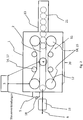
- Fig. 2 shows an examination unit 1 according to the invention in a bottom view.
- the camera 4 which is arranged within a conveying path 2 and looks from above on the transport past her body of the material to be treated.
- a feed device 13 introduces pre and end singled bodies into the effective area of the conveying path 2 and accelerates this possibly to the prevailing in the conveyor 2 transport speed v. 2
- the transport is achieved according to the invention by two bands 12, which are each endlessly circulating around two drive wheels 15. In this example, no guide wheel is present, otherwise one of the two drive wheels 15 of a belt 12 would be designed as such.
- Per band 12 two wheels 17 are further provided, which are the respectively associated band 12 so exciting that it does not flutter despite the high belt speeds of 5 m / s.
- the actual conveying path 2 is formed by a section 20, in which the two bands run facing each other approximately parallel.
- Applicable bands 12 have a soft but rough surface suitable for vigorously and gently contacting the material to be treated.
- the width between the bands 12 in the section 20 is adjustable slightly smaller than the outer diameter of the material to be treated.
- the bands 12 may be constructed of toothed belts and multi-layered and they may rotate at mutually different speeds.
- the examination unit 1 is already designed ejecting the body in the free horizontal throw.
- a separate unit 5 is arranged so that it is influencing the trajectory body accurate and error-dependent changing.
Abstract
Die vorliegende Erfindung betrifft ein Verfahren und eine Vorrichtung zum Transport und zur Untersuchung von schnelllaufenden Behandlungsgütern, aufweisend eine Untersuchungseinheit und eine Aussonderungseinheit.The present invention relates to a method and apparatus for transporting and inspecting high-speed items, comprising an examination unit and a disposal unit.
Description
Die vorliegende Erfindung betrifft eine Vorrichtung und ein Verfahren zum Transport und zur Untersuchung von schnelllaufenden, vereinzelten Körpern von Verpackungsbestandteilen und Verpackungsvorläufern mit mindestens einer Mantelfläche und mindestens einer Deckenfläche.The present invention relates to an apparatus and a method for transporting and inspecting high-speed, separated bodies of packaging components and packaging precursors having at least one lateral surface and at least one ceiling surface.
Derartige einzelne Körper, von Verpackungen oder Verpackungsbestandteilen, bzw. Verpackungsvorläufern sind beispielsweise Preforms für Blasformverfahren, PET-Flaschen, Joghurtbecher, Behälter, Deckel, Verschlüsse, Schraubdeckel oder allgemein zylindrische, einseitig geschlossene Hohlkörper, die oftmals als mehrschichtige Kunststoffkörper aufgebaut sind. Diese Körper weisen also mindestens eine Mantelfläche und eine Deckenfläche auf, wobei die Deckenfläche eine Öffnung enthalten kann. Sie können ebenfalls eine zur Deckenfläche überwiegend parallele Bodenfläche aufweisen, sofern diese nicht von der Mantelfläche nach Art eines Kegels oder abgerundeten Kegels gebildet wird, wie es beispielsweise bei Preforms der Fall ist.Such individual bodies of packaging or packaging components, or packaging precursors are, for example, preforms for blow molding, PET bottles, yogurt cups, containers, lids, closures, screw caps or generally cylindrical, closed on one side hollow body, which are often constructed as a multilayer plastic body. Thus, these bodies have at least one lateral surface and a ceiling surface, wherein the ceiling surface may include an opening. They can likewise have a floor surface which is predominantly parallel to the ceiling surface, provided that it is not formed by the lateral surface in the manner of a cone or rounded cone, as is the case, for example, with preforms.
Diese Körper müssen in vielen technischen Anwendungen manipuliert und auf ihre Qualität hin untersucht werden. Gerade in der Lebensmittelindustrie müssen aus wirtschaftlichen Gründen in kürzester Zeit große Mengen verpackt werden, wobei ausschließlich mechanisch und optisch fehlerlose Verpackungen oder Verpackungsbestandteile verwendet werden dürfen. Diese müssen zunächst hergestellt, dann vereinzelt und danach auf Fehler kontrolliert werden, woran sich eine Aussonderung der als fehlerhaft erkannten Verpackungen anschließt, bevor die so geprüften Verpackungen an die Verpackungsmaschine für den Verpackungsvorgang herangeführt werden. Hierbei sind mindestens 1.500 einzelne Körper des Behandlungsgutes pro Minute zu bewältigen, so daß pro Körper weniger als 40 ms zur Verfügung stehen, in denen er transportiert, geprüft und ausgesondert werden muß. Bei noch höheren Stückzahlen steht hierfür entsprechend weniger Zeit pro Körper zur Verfügung. Der Vereinzelungs-, Kontroll- und Aussortiervorgang stellt daher einen wesentlichen Engpass des Verpackungsvorganges dar und muss entsprechend schnell und zuverlässig durchgeführt werden.These bodies must be manipulated in many technical applications and examined for their quality. Especially in the food industry large quantities must be packed in a very short time for economic reasons, with only mechanically and visually flawless packaging or packaging components may be used. These must first be produced, then isolated and then checked for errors, followed by a separation of the identified as defective packaging before the so-tested packages are brought to the packaging machine for the packaging process. Here are at least 1,500 individual bodies of the material to be treated per minute, so that less than 40 ms are available per body, in which it must be transported, checked and discarded. With still higher numbers of pieces correspondingly less time per body is available for this. The separation, control and sorting process therefore represents a major bottleneck in the packaging process and must be carried out accordingly quickly and reliably.
Eine Vereinzelungsvorrichtung für derartige Verpackungen, bzw. Verpackungsbestandteile ist aus der
Aus der
Die vorliegende Erfindung stellt sich vor diesem Hintergrund des Standes der Technik die Verfahrensaufgabe, einen besonders schnellen und zuverlässigen Kontroll- und Aussonderungsschritt vorzuschlagen und die Vorrichtungsaufgabe, eine entsprechende Vorrichtung vorzuschlagen.The present invention, in this background of the prior art, proposes the process task of proposing a particularly fast and reliable checking and rejecting step and the device task of proposing a corresponding device.
Die Verfahrensaufgabe wird durch ein Verfahren zum Transport und zur Untersuchung von schnelllaufenden Körpern von Verpackungsbestandteilen und Verpackungsvorläufern mit mindestens einer Mantelfläche und mindestens einer Deckenfläche gelöst, bei dem an eine Untersuchungseinheit herantransportierte Körper des Behandlungsgutes von dieser in einen Förderweg übernommen werden, der Förderweg die Körper an wenigsten einer, mit einer Steuereinheit verbundenen, Kontrollkamera vorbeiführt, die Steuereinheit anhand der von der Kontrollkamera stammenden Bilddaten die Fehlerbehaftetheit jedes Körpers feststellt und die Untersuchungseinheit die Körper an eine Aussondereinheit übergibt, wobei entweder die Untersuchungseinheit oder die Aussondereinheit die Körper auswirft, insbesondere annähernd im freien Wurf, und wobei die Aussondereinheit die Flugbahnen von als fehlerhaft erkannten Körpern und von als fehlerfrei erkannten Körpern relativ zueinander mittels einer berührungslosen Kraftausübung ändert. Mit großem Vorteil erlaubt dieses Verfahren einen sehr schnellen Gesamtvorgang von Transport, Kontrolle und Aussonderung, insbesondere durch das Ausfördern im Wurf, insbesondere im annähernd freien Wurf. Eine Wurfausförderung verzichtet mit Vorteil auf Gleitbahnen, Leitglieder oder dergleichen, sie ist konstruktiv einfach und mangels beweglicher Teile auch verschleißarm. Die Lage der Flugbahn im Raum ist erfindungsgemäß innerhalb sehr großer Grenzen variabel, erfindungsgemäß kann der Wurfwinkel annähernd null sein, die Wurfbahn also annähernd senkrecht nach unten zeigen, er kann 45° betragen, die Wurfbahn also schräg nach unten zeigen, 90° betragen, die Wurfbahn also etwa gerade sein, aber auch stumpfe Winkel erfassen, die Wurfbahn also schräg nach oben oder sogar steil nach oben zeigen. Durch die Wahl der geeigneten Flugbahn werden unterschiedliche Wurfweiten und Flugzeiten und damit auch unterschiedliche Möglichkeiten für eine Flugbahnänderung eröffnet. Zunächst bevorzugt sind annähernd horizontale oder leicht nach unten gerichtete Würfe. Bevorzugt sind ebenfalls berührungslose Kraftausübungen, beispielsweise mittels eines Druckluftstoßes, da diese ohne zusätzlichen mechanischen Kontakt zu dem einzelnen ausgeworfenen Körper auskommen und daher diesen auch nicht beschädigen. Da die Körper des Behandlungsgutes dieselben geometrischen Formen, dieselbe Masse und dieselbe Geschwindigkeit haben, ist auch ihre jeweilige Flugbahn gleich, daß heißt, nur innerhalb sehr eng begrenzter Parameter schwankend. Aufgrund dieser in praktischem Maße identischen Flugbahn ist eine genaue mechanische Führung für den Aussondervorgang nicht erforderlich. Der Steuereinheit steht derjenige Zeitraum pro bewegtem Körper des Behandlungsgutes zur Verfügung, der zwischen Bildaufnahme und Eintritt in den Wirkbereich der Aussondereinheit liegt. Da im freien Flug außer der Schwerkraft keine weiteren Kräfte auf die Gegenstände einwirken, ist eine Kraftausübung auf die Gegenstände in Richtung der Schwerkraft besonders wirksam, um die jeweilige Flugbahn zu verändern. Erfindungsgemäß kann die Krafteinwirkung jedoch auch in jedem anderen Winkel zur Schwerkraft erfolgen, ausdrücklich auch seitlich oder entgegengesetzt dazu, also flugbahnverlängernd. Zusätzlich zu dem bereits genannten berührungslosen Mittel, versteht die Erfindung unter berührungslos alle Maßnahmen, die ohne unmittelbaren mechanischen Kontakt zwischen Aussondereinheit und Behandlungsgut auskommen, also beispielsweise die Einwirkung von elektrischen oder magnetischen Felder oder von Druckwellen. Unter Kontrollkamera versteht die Erfindung zunächst jede Art von optischen (Tageslicht)Kameras, jedoch auch IR-Kameras oder andere, schnell arbeitende Bildaufnahmesysteme. Die Erfindung versteht unter Kontrollkamera darüber hinaus jeglichen anderen Sensor, der relevante Eigenschaften des Körpers erfaßt, wie beispielsweise Farbsensoren, die das Vorhandensein einer Farbe und deren Parameter erkennen, also auch Sensoren, die beispielsweise die Maßhaltigkeit der Körper erkennen können. Letztere können beispielsweise Messfühler, Dehnstreifen, Kontaktsensoren oder dergleichen sein, die bei Nichteinhaltung der geforderten Maße ein entsprechendes Signal an die Steuereinheit senden, das nicht notwendigerweise ein Bild sein muss sondern sogar nur ein reines Ja/Nein-Signal sein kann. Bei bestimmten Anwendungen ist die Verwendung einer IR-Kamera, insbesondere einer gekühlten IR-Kamera von großem Vorteil, da diese körpergenaue Aufnahmen in kürzester Folge ermöglicht, so daß Verarbeitungsgeschwindigkeiten von mehr als 2500 Körper/min erreicht werden. Die gekühlte IR-Kamera benötigt dabei weniger als 0,5 ms für eine Aufnahme, stellt also keinen Verarbeitungsengpaß dar und erlaubt es, im sichtbaren Licht nicht sichtbare Strukturen der Körper zu kontrollieren. Genannt seien hier EVOH-Schichten oder dergleichen mehr. Die Erfindung verwendet dabei mindestens eine Kontrollkamera, jedoch sind auch vier oder mehr Kontrollkameras üblich, sofern die geometrische Struktur der Körper nur durch eine Mehrzahl an Kameras ausreichend erfaßt werden kann. Die Kontrollkameras sind dabei an den von ihnen jeweils zu beobachten Abschnitt des Körpers auszurichten, also seitlich, schräg oder senkrecht blickend anzuordnen, die Abfolge der Blickrichtungen während des Transports der Körper ist frei wählbar, eine Bodenkontrolle muss nicht zwingend vor einer Seitenkontrolle erfolgen oder gar unbedingt vorhanden sein.The process object is achieved by a method for transporting and inspecting high-speed bodies of packaging components and packaging precursors having at least one lateral surface and at least one ceiling surface, in which an examination unit transported body of the material to be treated are taken from this in a conveying path, the conveying path passes the body of at least one, connected to a control unit, control camera, the control unit based on the originating from the control camera image data detects the error liability of each body and the examination unit to the body a Aussondereinheit passes, wherein either the examination unit or the Aussondereinheit ejects the body, in particular approximately in the free throw, and wherein the Aussondereinheit changes the trajectories of recognized as faulty bodies and recognized as faultless bodies relative to each other by means of a non-contact power application. With great advantage, this method allows a very fast overall process of transport, control and segregation, in particular by the discharge in the litter, especially in approximately free litter. A litter removal dispensed with advantage on slides, guide members or the like, it is structurally simple and lack of moving parts also wear. The position of the trajectory in space according to the invention is variable within very large limits, according to the invention, the throw angle can be approximately zero, so the trajectory pointing approximately vertically downwards, it can be 45 °, so the trajectory pointing obliquely downward, 90 °, the So be trajectory about straight, but also detect obtuse angles, so the trajectory so obliquely upwards or even show upwards. By choosing the appropriate trajectory different casting distances and times and thus also different possibilities for a trajectory change are opened. First preferred are approximately horizontal or slightly downward throws. Also preferred are non-contact exertion of force, for example by means of a blast of compressed air, since these get along without additional mechanical contact to the individual ejected body and therefore this also do not damage. Since the bodies of the material to be treated have the same geometric shapes, the same mass and the same speed, their respective trajectories are the same, that is, they fluctuate only within very narrow parameters. Due to this practically identical trajectory precise mechanical guidance for the Aussondervorgang is not required. The control unit is the period of time per moving body of the material to be treated, which is between image acquisition and entry into the effective range of Aussondereinheit. Since no other forces act on the objects in free flight except gravity, an application of force to the objects in the direction of gravity is particularly effective in order to change the respective trajectory. However, according to the invention, the action of force can also take place at any other angle to the force of gravity, specifically also laterally or oppositely thereto, that is to say extension of the trajectory. In addition to the already mentioned non-contact means, the invention means contactless all measures that do not require direct mechanical contact between Aussondereinheit and treated, so for example, the action of electric or magnetic fields or pressure waves. Under control camera, the invention initially understands any type of optical (daylight) cameras, but also IR cameras or other fast-acting imaging systems. The invention also includes a control camera any other sensor that detects relevant properties of the body, such as color sensors that detect the presence of a color and their parameters, including sensors that can detect, for example, the dimensional accuracy of the body. The latter can be, for example, sensors, strain gauges, contact sensors or the like, which, if the required dimensions are not met, send a corresponding signal to the control unit, which does not necessarily have to be an image but only a pure yes / no signal can be. In certain applications, the use of an IR camera, in particular a cooled IR camera, is of great advantage, as it enables accurate imaging in the shortest possible sequence, so that processing speeds of more than 2500 body / min are achieved. The cooled IR camera requires less than 0.5 ms for a recording, so is no processing bottleneck and allows to control in the visible light not visible structures of the body. Mentioned here are more EVOH layers or the like. The invention uses at least one control camera, but four or more control cameras are common, provided that the geometric structure of the body can be sufficiently detected only by a plurality of cameras. The control cameras have to be aligned with the part of the body to be observed by them, ie laterally, obliquely or vertically looking, the sequence of viewing directions during the transport of the body is freely selectable, a ground control does not necessarily take place before a side control or even necessarily to be available.
Erfindungsgemäß wirkt die Aussondereinheit unmittelbar am Ende des Förderweges oder beabstandet zum Ende des Förderweges. Wirkt die Aussondereinheit erfindungsgemäß unmittelbar benachbart zur Untersuchungseinheit, ist die Flugbahn besonders kurz, da eine umgehende Beeinflussung der Flugbahn erfolgt. Durch die so erreichte, sehr kurze Bauweise der Aussonderungseinheit wird keine im Grunde genommen leere Zeit für einen weiteren Transport der Behandlungsgüter zur Aussondereinheit benötigt, vielmehr erfolgt die Aussonderung unmittelbar nach deren Durchlauf durch die Untersuchungseinheit. Im anderen Fall wirft bereits die Untersuchungseinheit die untersuchten Gegenstände im Wurf aus, deren Flugbahn durch den Wirkbereich der Aussondereinheit führt. Diese wiederum verändert dann die Flugbahn der frei fliegenden Körper wie geschildert. Die räumliche Trennung von Untersuchungs- und Aussondereinheit erlaubt mit Vorteil die Zwischenschaltung weiterer Kontrollkameras oder-einrichtungen, die bislang nicht untersuchte Bereiche der Körper ungestört von irgendwelchen Halte- oder Führungsorganen untersuchen. Dies stellt eine gute Ergänzung zu den Untersuchungsmitteln dar, die bereits im Bereich der Untersuchungseinheit eingesetzt wurden. Im freien Flug ist die Körperoberfläche ohne Behinderung zugänglich und damit untersuchbar.According to the invention, the separating unit acts directly at the end of the conveying path or at a distance from the end of the conveying path. If the Aussondereinheit acts according to the invention immediately adjacent to the examination unit, the trajectory is particularly short, since an immediate influence on the trajectory takes place. Due to the very short design of the separation unit achieved in this way, no basically empty time is required for a further transport of the treatment goods to the removal unit, rather the separation takes place immediately after passing through the examination unit. In the other case, the examination unit already ejects the examined objects in the litter whose trajectory leads through the effective range of the litter unit. This then changes the trajectory of the free-flying body as described. The spatial separation of examination and secretion unit advantageously allows the interposition of other control cameras or devices that examine previously unexamined areas of the body undisturbed by any holding or guiding organs. This is a good supplement to the investigational devices that have already been used in the area of the examination unit. In free flight, the body surface is accessible without obstruction and thus examined.
Das erfindungsgemäße Verfahren sieht wie beschrieben vor, dass die Aussonderungseinheit eine Kraft mittels einer berührungslosen Kraftausübung auf die Körper ausübt. Von den genannten berührungslosen Kraftausübungen ist besonders der Druckluftstoß bevorzugt. Dieser ist aufgrund der Kürze der zur Verfügung stehenden Zeit pro Körper des Behandlungsgutes ideal, da hierzu lediglich ein Ventil geöffnet und geschlossen werden muss. Mit großem Vorteil werden beweglichen Teile vermieden, die zeitintensiv wieder auf ihre Ausgangsposition zurückgeführt werden müssten. Auch eine mechanische Beeinflussung der Flugbahn durch Anschlags- oder Führungskanten wird mit Vorteil vermieden, es kann kein Abrieb, kein Verklemmen oder dergleichen geben. Schließlich steht Druckluft üblicherweise problemlos an jedem Aufstellort der Vorrichtung, bzw. an jedem Einsatzort des Verfahrens zur Verfügung. Aufgrund der sich im unteren Millisekundenbereich bewegenden Reaktionszeit sind jedoch nicht sämtliche Druckluftventile geeignet, diese müssen vielmehr entsprechend geringe Öffnungs- und Schließzeiten aufweisen, auch muss ein ausreichend großer Startdruck vorhanden sein. Schließlich sollte die auf das Behandlungsgut auftreffende Luftmenge bis dahin weder stärker aufgefächert worden sein, noch einen allzu langen Weg zurückgelegt haben, um so impulsartig ortsgenau aufzutreffen und ausschließlich das jeweilige gewünschte Behandlungsgut zu beeinflussen. Dies ist besonders wichtig, da im Gegensatz zu Vorrichtungen für nicht vereinzelte Massengüter wie Reiskörner, Tabakblätter oder dergleichen eine körpergenaue Aussonderung erforderlich ist, um den Ausschuß so gering wie möglich zu halten und vor allem, um die wesentlich größeren Körper des erfindungsgemäßen Verfahrens bzw. der Vorrichtung ausreichend mit Kraft zur Flugbahnänderung beaufschlagen zu können. Ein verwendbares Ventil muss daher diese Eigenschaften aufweisen.As described, the method according to the invention provides that the rejection unit exerts a force on the bodies by means of non-contact exertion of force. Of the said non-contact exertion of force especially the compressed air surge is preferred. This is ideal due to the shortness of the available time per body of the material to be treated, since this only one valve must be opened and closed. With great advantage moving parts are avoided, which would have to be returned to their original position time-consuming. A mechanical influence on the trajectory by stop or leading edges is avoided with advantage, there can be no abrasion, no jamming or the like. Finally, compressed air is usually easily available at each installation site of the device, or at each site of the method. Due to the moving in the lower millisecond range reaction time, however, not all compressed air valves are suitable, these must have rather correspondingly small opening and closing times, and a sufficiently large starting pressure must be present. Finally, the amount of air impinging on the material to be treated should not have been fanned out to a greater extent, nor have they covered too long a path so as to impinge in a pulse-like manner and exclusively influence the respective desired material to be treated. This is special important because in contrast to devices for non-isolated bulk commodities such as rice grains, tobacco leaves or the like a body-specific disposal is required to keep the Committee as low as possible and especially to the much larger body of the method and the device sufficiently with Force to act on the trajectory change. A suitable valve must therefore have these properties.
Erfindungsgemäß führt der Förderweg die Körper boden- und/oder deckenfrei an der wenigstens einen Kontrollkamera vorbei, so dass diese den Boden, die Deckfläche oder Boden und Deckfläche untersuchen kann. Dies erfolgt insbesondere mittels eines reibschlüssigen parallelen Bandlaufes, wie weiter unten erläutert wird.According to the invention, the conveying path guides the bodies past the at least one control camera, free of floor and / or ceiling, so that they can examine the floor, the top surface or bottom and top surface. This is done in particular by means of a frictional parallel tape run, as will be explained below.
Erfindungsgemäß ist weiter vorgesehen, dass der Förderweg der Untersuchungseinheit die Körper während ihrer Passage durch die Untersuchungseinheit um ihre Längsachse dreht, beispielsweise durch zwei unterschiedliche schnell laufende Bänder. Hierdurch mit wird großem Vorteil eine Prüfung des gesamten Körperumfanges in der Untersuchungseinheit ermöglicht, beispielsweise mit drei oder mehr Aufnahmen entlang des Förderweges dank einer entsprechenden Anzahl an Kameras.According to the invention it is further provided that the conveying path of the examination unit rotates the body during its passage through the examination unit about its longitudinal axis, for example by means of two different fast-moving bands. As a result, with great advantage, an examination of the entire body circumference in the examination unit allows, for example, with three or more shots along the conveying path thanks to a corresponding number of cameras.
In Weiterbildung des Verfahrens ist vorgesehen, das wenigsten eine Kontrollkamera eine Boden- und wenigstens eine Kontrollkamera eine Seitenfläche der Körper aufnimmt, insbesondere die im freien Flug befindlichen Körpern vor der Aussortierung einer seitlichen Kontrolle durch auf ihre Seite blickende Kontrollkameras, bis zu vier oder mehr, unterzogen werden, wobei sämtliche Kontrollkameras mit der Steuer- und Auswerteeinheit verbunden sind. Das Verfahren ermöglicht so die vollständige Oberflächenkontrolle der zu behandelnden Körper, insbesondere auch durch Einsatz von mehr als zwei Sensoren/Kontrollkameras. Die Kontrolle ist erfindungsgemäß durch schnelle Tageslichtkameras genauso möglich, wie durch sehr schnell arbeitende gekühlte IR-Kameras, die Belichtungszeiten von wenigen Hundert Mikrosekunden aufweisen und die jeden einzelnen Körper des Behandlungsgutes exakt und positionsgenau erfassen. Letztere werden besonders dann erfindungsgemäß vorgesehen, wenn die Körper auf die Güte einer im sichtbaren Licht nicht erkennbaren Sperrschicht kontrolliert werden müssen. Der Erfindung kommt es dabei nicht darauf an, ob zunächst eine Boden- oder Deckelseite und danach eine Seitenkontrolle der Körper erfolgen oder umgekehrt. Es ist ohne weiteres erfindungsgemäß, im freien Fluge auch die Boden- bzw. Deckelseite mit den Sensoren zu erfassen, wenn vorher die Seiten erfaßt wurden. Ebenso ist es erfindungsgemäß, wenn im freien Fluge kein Sensorik mehr angewandt wird sondern die Oberflächenkontrolle bereits vor dem Aussonderungsschritt in der Untersuchungseinheit mithilfe von dort angeordneten Kameras in Decken-, Boden- und/oder Seitenlage erfolgt ist.In a further development of the method it is provided that at least one control camera a ground and at least one control camera receives a side surface of the body, in particular the bodies in free flight before sorting out a lateral control by looking to their side control cameras, up to four or more, be subjected, with all control cameras are connected to the control and evaluation. The method thus allows the complete surface control of the body to be treated, especially by using more than two sensors / control cameras. The control according to the invention by fast daylight cameras just as possible, as by very fast-working cooled IR cameras having exposure times of a few hundred microseconds and detect each individual body of the treated material accurately and accurately. The latter are particularly provided according to the invention, when the body must be controlled to the quality of a non-visible in the visible light barrier. The invention does not depend on whether first a bottom or top side and then a side control of the body or vice versa. It is readily according to the invention to detect in the free flight and the bottom or cover side with the sensors when the pages were previously detected. Likewise, it is according to the invention, if in the free flight no more sensors are applied but the surface control is done even before the screening step in the examination unit using there arranged cameras in ceiling, floor and / or side position.
In Ausgestaltung des Verfahrens ist weiter vorgesehen, daß wenigstens eine Flugbahn an einer Trennoberfläche eines Trennkörpers vorbeiführt, insbesondere jede Flugbahn an je einer Trennoberfläche vorbeiführt, wobei beide Trennoberflächen einen Winkel zwischen sich einschließen. Durch diese kontaktfreie Trennvorrichtung wird die Sicherheit des Aussondervorganges mit Vorteil weiter erhöht, da die bereits eingeleitete Flugbahntrennung nicht wieder rückgängig gemacht werden kann, beispielsweise durch unbeabsichtigte Verwirbelungen oder Luftstöße. Die einmal getrennten Körper verbleiben auf ihren durch Trennoberflächen voneinander getrennten Flugbahnen.In an embodiment of the method is further provided that at least one trajectory past a separating surface of a separating body, in particular passes each trajectory on a respective separating surface, wherein both separating surfaces form an angle between them. Through this non-contact separation device, the safety of Aussondervorganges advantageously further increased, since the already initiated trajectory separation can not be reversed again, for example by unintentional turbulence or air surges. The once separated bodies remain on their separated by separation surfaces trajectories.
Schließlich ist in Weiterbildung des Verfahrens noch vorgesehen, daß nur die als fehlerfrei ermittelten Körper des Behandlungsgutes in ihrer Flugbahn verändert werden. Dies erhöht die Sicherheit des Aussonderungsverfahrens, da im Falle eines Fehlers an der Aussondereinheit alle Behandlungsgüter ausgesondert werden und so keinesfalls ein als schad- oder fehlerhaft erkanntes Behandlungsgut irrtümlich doch zu den als fehlerfrei gewerteten gelangen kann.Finally, it is provided in a further development of the method that only the determined as faultless body of the material to be treated are changed in their trajectory. This increases the safety of the screening process, since in the event of a fault on the Aussondereinheit all items are discarded and so in no case recognized as harmful or faulty material treated erroneously but can reach the rated as error-free.
Es ist erfindungsgemäß ebenfalls vorgesehen, daß die im freien Flug befindlichen Körper vor der Aussortierung einer seitlichen Kontrolle durch auf ihre Seite blickende Kontrollkameras unterzogen werden, wobei diese Sensoren ebenfalls mit der Steuer- und Auswerteeinheit verbunden sind. Die Aussortierung erfolgt dann in einem späteren Stadium des freien Fluges. Hierdurch kann mit Vorteil eine Dokumentation der vollständigen Körperoberfläche und damit ein sehr hohes Maß an Qualitätskontrolle erreicht werden. Schließlich ist bei bestimmtem Behandlungsgut auch die auf- und/oder untersichtige Kontrolle wichtig, insbesondere bei Deckeln, da die so beobachtete Stirnfläche gleichzeitig die relevanteste Fläche des Körpers ist, was bereits erläutert wurde.It is also provided according to the invention that the bodies in free flight are subjected to a lateral control by looking to their side control cameras before sorting out, these sensors are also connected to the control and evaluation unit. The sorting then takes place at a later stage of free flight. This can be achieved with advantage a documentation of the entire body surface and thus a very high level of quality control. Finally, for certain items to be treated and the up and / or subordinate control is important, especially in lids, since the thus observed face is also the most relevant surface of the body, which has already been explained.
Schließlich erfaßt des erfindungsgemäße Verfahren auch eine zweite, der ersten nachgeordnete Aussonderung. Diese sehr vorteilhafte Weiterbildung ermöglicht eine zusätzliche Sicherung gegen fehlerhafte Verfahrensabläufe. Sollte der erste Aussonderungsschritt nicht erfolgreich sein, beispielsweise weil die Kamera, die Datenweiterleitung, die Datenverarbeitung, die Druckluftsteuerung oder ähnliches nicht funktionieren, so verhindert dieser zweite Aussonderungsschritt das fälschliche Freigeben nicht-geprüfter oder fehlerhafter, aber nicht ausgesonderter Körper. Dieser zweite Aussonderungsschritt sperrt erfindungsgemäß die Flugbahn sämtlicher Körper und verhindert so, daß auch nur ein fehlerhaftes Verpackungsteil durchgelassen wird. Das Sperren kann berührungslos, insbesondere per Druckluftstoß, oder berührend geschehen, beispielsweise durch Verfahren eines Arms, einer Sperre oder allgemein eines physischen Körpers in die Flugbahn(en) der Körper. Erfindungsgemäß ist auch, wenn lediglich der als fehlerhaft erkannte, aber im ersten Aussonderungsschritt nicht ausgesonderte Körper ausgesondert wird.Finally, the method according to the invention also detects a second, the first subordinate rejection. This very advantageous development allows additional protection against incorrect procedures. Should the first discard step be unsuccessful, for example because the camera, data relay, data processing, compressed air control or the like does not work, then this second discarding step prevents the erroneous release of unchecked or faulted but unrecorded body. According to the invention, this second rejection step blocks the trajectory of all bodies and thus prevents even only a faulty packaging part from being let through. The Locking can be done without contact, in particular by a blast of compressed air, or touching, for example by moving an arm, a lock or generally a physical body in the trajectory (s) of the body. It is also according to the invention if only the body recognized as defective but not separated out in the first rejection step is discarded.
Die Vorrichtungsaufgabe wird bei einer Vorrichtung zum Transport und zur Untersuchung von vereinzelten, schnelllaufenden Körpern von Verpackungsbestandteilen und Verpackungsvorläufern mit mindestens einer Mantelfläche und mindestens einer Deckenfläche, aufweisend a) eine Untersuchungseinheit, wobei die Untersuchungseinheit wenigstens eine Kontrollkamera und eine mit dieser verbundenen Steuereinheit sowie eine Transportvorrichtung aufweist, wobei die Transportvorrichtung die Körper des Behandlungsgutes an der wenigstens einen Kontrollkamera vorbei transportierend ist, wobei die Steuereinheit die Fehlerbehaftetheit jedes Körpers anhand der von der wenigstens einen Kontrollkamera stammenden Bilddaten ermittelnd ist und b) weiter aufweisend eine mit der Untersuchungseinheit funktionsmäßig verbunden ausgebildeten Aussondereinheit, wobei die Aussondereinheit von der Untersuchungseinheit Körper übernehmend ist, wobei entweder die Untersuchungseinheit oder die Aussondereinheit die Körper im freien Wurf auswerfend ist, wobei die Aussondereinheit die Flugbahnen von als fehlerhaft erkannten Körpern und von als fehlerfrei erkannten Körpern relativ zueinander mittels einer berührungslosen Kraftausübung beeinflussend ist. Die Vorteile dieser Vorrichtung wurden bereits bei der Erläuterung des erfindungsgemäßen Verfahrens erläutert.The device task is in a device for transporting and inspecting isolated, high-speed bodies of packaging components and packaging precursors having at least one lateral surface and at least one ceiling surface, comprising a) an examination unit, wherein the examination unit at least one control camera and a control unit connected thereto and a transport device wherein the transport device is transporting the bodies of the material to be treated past the at least one control camera, wherein the control unit determines the faultiness of each body on the basis of the image data originating from the at least one control camera; and b) further comprising a removal unit functionally connected to the examination unit, wherein the secretion unit of the examination unit is body receiving, whereby either the examination unit or the secretion unit the K body is throwing out in the free throw, wherein the Aussondereinheit the trajectories of detected as defective bodies and detected as error-free bodies relative to each other is influencing means of a contactless exertion of force. The advantages of this device have already been explained in the explanation of the method according to the invention.
In Weiterbildung der Vorrichtung ist vorgesehen, dass die Transportvorrichtung die Körper boden- und/oder deckenfrei an wenigsten einer Kontrollkamera der Untersuchungseinheit vorbeitransportierend ist.In a further development of the device is provided that the transport device, the body floor and / or blanket is transported past at least a control camera of the examination unit.
Die Transportvorrichtung kann erfindungsgemäß auch, mindestens teilweise, als Oberführung ausgebildet sein, also die Körper an deren Deckfläche halten, beispielsweise als Vakuumband. In jedem Fall muss die Transportvorrichtung die Körper ruhig vor der Kamera vorbeiführen, also Pendelbewegungen oder Schrägstellungen unbedingt vermeiden. Ist sie vor der Kamera als Oberführung ausgebildet, so ist erfindungsgemäß vorgesehen, sie an ihrem kameraseitigen Ende keilförmig oder schwalbenschwanzförmig auslaufend zu gestalten. Die genannten Formen ergeben sich jeweils in Auf- bzw. Untersicht. Hierdurch wird erreicht, daß die Körper günstig an einer Randlage, also radial weit außen, zuletzt berührt werden, im zweiten Fall erfolgt die Berührung sogar symmetrisch. Hierdurch werden für die Aufnahme der Oberseite der Körper oder deren Unterseite ungünstige Schrägstellungen oder Bewegungen vermieden, was insbesondere bei Preforms besonders wichtig ist. Sollen lediglich Seitenkameras eingesetzt werden, kann die gesamte Transportvorrichtung als Oberführung ausgebildet sein. In diesem Fall ist die genannte Endform im Bereich der Übergabe an die Aussondereinheit vorzusehen, um stets gleiche Fluglagen der Körper zu gewährleisten.According to the invention, the transport device may also be designed, at least in part, as an upper guide, that is to say hold the bodies on their cover surface, for example as a vacuum belt. In any case, the transport device must pass the body quietly in front of the camera, so avoid pendulum movements or inclinations. If it is formed in front of the camera as an upper guide, it is provided according to the invention to make it wedge-shaped or dovetailed at its end at the camera end. The forms mentioned arise in each case in top or bottom view. This ensures that the body is low on a peripheral position, ie radially outward, last touched, in the second case, the touch is even symmetrical. As a result, unfavorable inclinations or movements are avoided for receiving the top of the body or the underside, which is particularly important in preforms. If only side cameras are to be used, the entire transport device can be designed as an upper guide. In this case, the said final shape in the area of the transfer to the Aussondereinheit provided in order to ensure always the same attitude of the body.
In Weiterbildung der Vorrichtung ist vorgesehen, dass die Transportvorrichtung zwei, um je ein Antriebsrad und ein weiteres Rad umlaufende, angetriebene und vorgespannte Bänder aufweist, die zwischen sich einen Förderweg definieren. Ein derartiger Bandtransport erlaubt ein weiches, beschädigungsfreies Führen der Körper unter ausreichender Klemmkraft, so daß die Körper drehfest geführt und eine zweifelsfreie Aufnahme ermöglichend sind. Der Abstand der beiden Bänder im Förderweg ist daher etwas geringer als der freie Außendurchmesser der Körper. Durch umlaufende Bänder können konstruktiv einfach hohe Transportgeschwindigkeiten erreicht werden, beispielsweise 5m/s. Der erfindungsgemäß vorgesehen Bandtransport hat darüber hinaus den Vorteil, Schwankungen in der Körperzufuhr problemlos zu bewältigen, ein bestimmter Abstand der Körper zueinander wie bei einem Drehteller- oder einem Nesttransport ist nicht erforderlich.In a development of the device, it is provided that the transport device has two driven and pretensioned belts, each revolving around a drive wheel and a further wheel, which define a conveying path between them. Such a belt transport allows a soft, damage-free guidance of the body under sufficient clamping force, so that the body rotatably guided and a doubt-free recording are possible. The distance between the two belts in the conveying path is therefore slightly smaller than the free outer diameter of the body. By circulating belts can be achieved structurally simple high transport speeds, for example, 5m / s. The inventively provided tape transport also has the advantage of fluctuations in body supply to cope with a certain distance, the body to each other as a turntable or a nest transport is not required.
In Ausgestaltung der Erfindung ist vorgesehen, die Bänder der Transportvorrichtung mit zueinander unterschiedlicher Geschwindigkeit umlaufend sind. Die Vorteile dieser Ausgestaltung wurden bereits weiter oben erläutert.In an embodiment of the invention, it is provided that the belts of the transport device are revolving at mutually different speeds. The advantages of this embodiment have already been explained above.
Erfindungsgemäß ist weiter vorgesehen, dass mindestens ein Band als Zahnriemen ausgebildet ist, vorzugsweise beide Bänder und/oder ein Rad als Führungsrad und/oder ein Rad als zweites Antriebsrad und/oder wenigstens ein Laufrad pro Band vorgesehen ist. Bei den geforderten hohen Transportgeschwindigkeiten sind allein reibschlüssig angetriebene Bänder auf die Dauer nicht unproblematisch, da deren Oberfläche durch gelegentliche Durchrutscher verglasen kann, so daß Zahnriemen mit Antriebszahnrädern vorteilhafter werden können. Der Einsatz von glatten Bandoberflächen ist erfindungsgemäß jedoch keinesfalls ausgeschlossen. Erfindungsgemäß können ein Antriebs- und ein Führungsrad oder zwei Antriebsräder pro Band vorgesehen sein. Zwischen diesen können ein oder mehrere Laufräder so angeordnet sein, daß diese zu einer gewissen Vorspannung des Bandes führen und dessen Flattern verhindern. Alternativ oder Zusätzlich können die Bänder mittels einer Federkraft vorgespannt sein, beispielsweise, indem die Laufräder radial verschieblich gegen eine Federkraft angeordnet sind.According to the invention it is further provided that at least one band is formed as a toothed belt, preferably both bands and / or a wheel as a guide wheel and / or a wheel as the second drive wheel and / or at least one impeller per band is provided. At the required high transport speeds alone frictionally driven belts are not unproblematic in the long run, since the surface can glaze through occasional slipping, so that timing belt with drive gears can be more advantageous. However, the use of smooth strip surfaces according to the invention is by no means excluded. According to the invention, one drive and one guide wheel or two drive wheels per band can be provided. Between these, one or more wheels may be arranged so that they lead to a certain bias of the band and prevent its flutter. Alternatively or additionally, the bands may be biased by a spring force, for example, by the wheels are arranged radially displaceable against a spring force.
In Ausgestaltung der Erfindung ist vorgesehen, dass die Aussondereinheit ein Druckluftventil aufweist, insbesondere ein Druckluftventil mit Schließ- und Öffnungszeiten von weniger als 3,5 ms. Die Vorteile dieser Ausgestaltung wurden zuvor beschrieben.In an embodiment of the invention it is provided that the Aussondereinheit has a compressed air valve, in particular a compressed air valve with closing and opening times of less than 3.5 ms. The advantages of this embodiment have been described above.
Schließlich ist noch vorgesehen, dass die Vorrichtung einen Trennkörper zur Trennung von Flugbahnen mit wenigstens einer Trennfläche aufweist, insbesondere mit zwei Trennflächen, die zwischen sich einen Winkel einschließend sind. Dieser Trennkörper verhindert ein Rückvermischen des bereits flugbahngetrennten fehlerlosen- und fehlerbehafteten Behandlungsgutes durch unbeabsichtigte Störungen.Finally, it is provided that the device has a separating body for the separation of trajectories with at least one separating surface, in particular with two parting surfaces which enclose an angle between them. This separator prevents backmixing of the already trajectory separated flawless and faulty material to be treated by unintentional disturbances.
Ist eine zweite, im Flugweg der Körper zur ersten nachfolgende Aussondereinheit vorgesehen, so wird wie geschildert, die Betriebssicherheit der Vorrichtung mit Vorteil erhöht. Sollte die erste Aussondereinheit oder gar die Untersuchungseinheit insgesamt ausfallen, so sperrt die zweite Aussondereinheit die Flugbahn der Körper vollständig und verhindert so, daß die Vorrichtung fehlerhafte Körper freigibt. Die gesamte Vorrichtung fährt dann in einen Fehlermodus und muß von einem Bediener nach Behebung der Fehlfunktion aktiv wieder freigegeben werden. Es ist daher ebenfalls erfindungsemäß, wenn bei der ersten Aussondereinheit eine Untereinheit vorgesehen ist, die das tatsächlich erfolgte Aussondern eines Körpers überprüft. Dies kann beispielsweise mittels einer vom ausgesonderten Körper zu durchquerenden Lichtschranke, einem drucksensitiven Feld, auf das der Körper aufprallt oder dergleichen mehr realisiert werden. Wenn also ein als fehlerhaft erkannter Körper diese beispielhafte Lichtschranke nicht durchquert, ist die erste Aussonderung gescheitert und die beschrieben zweite Aussonderungseinheit wird aktiv. Alternativ ist erfindungsgemäß auch vorgesehen, die Flugbahn der fehlerfreien Körper zu überwachen. Das bedeutet, daß die zweite Aussonderung aktiv wird, wenn ein Körper durch die Lichtschranke fliegt, der eigentlich vorher hätte ausgesondert werden sollen. Die zweite Aussondereinheit wird auch aktiv, wenn die Kamera beispielsweise keine Bilder liefert oder ein anderer Fehler stromaufwärts der zweiten Aussondereinheit vorliegt und sie diesen Fehler gemeldet erhält. Es ist auch erfindungsgemäß, wenn die zweite Aussondereinheit lediglich als Backup der ersten Aussondereinheit arbeitend ist und bei korrekt arbeitender Fehlererkennung durch Kamera und Steuerung jedoch lediglich nicht erfolgter Aussonderung des fehlerbehafteten Körpers in der ersten Aussondereinheit diesen Körper dann, beispielsweise wiederum per Druckluftstoß oder per mechanischer Kontaktierung, aussondernd ist.If a second, in the flight path of the body to the first subsequent Aussondereinheit provided so as described, the reliability of the device increases with advantage. Should the first spill unit or even the examination unit fail altogether, the second spill unit completely blocks the trajectory of the bodies and thus prevents the device from releasing defective bodies. The entire device then enters an error mode and must be actively enabled by an operator after the malfunction has been remedied. It is therefore also erfindungsemäß when a subunit is provided in the first secretion unit, which verifies the actually carried out a body. This can be realized, for example, by means of a light barrier to be traversed by the rejected body, a pressure-sensitive field on which the body impacts or the like. If, therefore, a body recognized as defective does not traverse this exemplary light barrier, the first rejection has failed and the described second rejection unit becomes active. Alternatively, it is also provided according to the invention to monitor the trajectory of the defect-free body. This means that the second rejection becomes active when a body flies through the photocell, which should have been ejected beforehand. The second discard unit also becomes active when, for example, the camera is not delivering pictures or another error is present upstream of the second discard unit and it receives this error. It is also according to the invention, when the second Aussondereinheit is working only as a backup of the first Aussondereinheit and correct working error detection by camera and control, however only failed rejection of the faulty body in the first Aussondereinheit this body then, for example, again by compressed air blast or by mechanical contact, herausondernd.
Schließlich ist erfindungsgemäß noch vorgesehen, dass die Untersuchungseinheit einen zweiten Förderweg aufweist, in dem die Körper boden- und/oder deckenseitig geführt sind, wobei dieser Förderweg an wenigstens einer auf die Körper blickenden Kontrollkamera vorbeiführend ist. Dieser zweite Förderweg kann sich unmittelbar an den ersten anschließen oder prozeßtechnisch vor diesem angeordnet sein. In beiden Fällen ist ein Übergabebereich zwischen den beiden Förderwegen vorzusehen. Wichtig ist der Erfindung, daß eine Kontrolle der Körper auch bereits vor der eigentlichen Untersuchungseinheit erfolgen kann, besonders, wenn dies zu einer kürzeren Baulänge der Vorrichtung führt oder aufgrund einer körperbedingt benötigten längeren Verarbeitungszeitspanne erforderlich ist.Finally, according to the invention, it is also provided that the examination unit has a second conveying path in which the bodies are guided on the floor and / or on the ceiling side, this conveying path being guided past at least one control camera looking at the body. This second conveying path can be connected directly to the first or arranged in front of it in terms of process technology. In both cases, a transfer area between the two conveying paths is provided. It is important to the invention that a control of the body can be done even before the actual examination unit, especially if this leads to a shorter overall length of the device or is required due to a body required longer processing time period.
Die zuvor genannten Merkmale erreichen mit großem Vorteil eine schnelle und zuverlässig arbeitende Vorrichtung bei geringem konstruktivem Aufwand.The aforementioned features achieve with great advantage a fast and reliable working device with low design effort.
Weitere Einzelheiten, vorteilhafte Weiterbildungen und eine bevorzugte Ausführungsform werden nachstehend anhand der Figurenbeschreibung näher erläutert. Hierbei zeigen
- Fig. 1:
- eine skizzenhafte Seitenansicht einer erfindungsgemäßen Vorrichtung und
- Fig. 2:
- eine Untersicht auf eine erfindungsgemäße Untersuchungseinheit.
- Fig. 1:
- a sketchy side view of a device according to the invention and
- Fig. 2:
- a bottom view of an examination unit according to the invention.
Gestrichelt und damit optional sind in
Mit dieser Erfindung können durchaus 4.500 Körper pro Minute behandelt und kontrolliert werden, jedoch sind auch mehr als 5.000 Körper pro Minute durch die Vorrichtung durchsetzbar. Die Kombination aus vorheriger vollständiger Vereinzelung, schnell laufenden Bändern 12, einer sehr schnellen Bildaufnahme durch eine Tageslicht- oder gekühlte IR-Kamera und eine berührungslos erfolgende Aussonderung der kontrollierten und als fehlerbehaftet erkannten Körper durch eine Veränderung ihrer Flugbahn ist besonders dazu geeignet, derart schnell laufendes Behandlungsgut zu bewältigen.With this invention, it is possible to treat and control 4,500 bodies per minute, but more than 5,000 bodies per minute can be enforced by the device. The combination of prior complete singulation, fast-moving
- 11
- Untersuchungseinheitinvestigation unit
- 22
- Förderwegconveying
- 33
- Steuereinheitcontrol unit
- 44
- Kontrollkameracontrol camera
- 55
- AussondereinheitAussondereinheit
- 66
- Flugbahntrajectory
- 77
- Flugbahntrajectory
- 88th
- Trennoberflächeparting surface
- 99
- Trennkörperseparating body
- 1010
- Seitliche KontrollkameraLateral control camera
- 1111
- Transportvorrichtungtransport device
- 1212
- Bandtape
- 1313
- Zufuhrvorrichtungfeeding apparatus
- 1414
- Radwheel
- 1515
- Antriebsraddrive wheel
- 1616
- 1717
- LaufradWheel
- 1818
- DruckluftventilAir Valve
- 1919
- Wirkbereicheffective range
- 2020
- Paralleler BandabschnittParallel band section
- 2121
- Körperbody
Claims (12)
wobei die Transportvorrichtung zwei, um je ein Antriebsrad (15) und ein weiteres Rad (14) umlaufende, angetriebene und vorgespannte Bänder (12) aufweist, die zwischen sich einen Förderweg definierend sind wobei die Transportvorrichtung (11) die vereinzelten und einander nicht kontaktierenden Körper (21) an der wenigstens einen Kontrollkamera (4) vorbei transportierend ist, wobei die Steuereinheit (3) die Fehlerbehaftetheit jedes Körpers (21) anhand der von der wenigstens einen Kontrollkamera (4) stammenden Bilddaten ermittelnd ist, und
wherein the transport device comprises two driven and prestressed belts (12) revolving around a respective drive wheel (15) and another wheel (14), defining a conveying path therebetween, the transport device (11) comprising the separated and non-contacting bodies (21) is transported past the at least one control camera (4), wherein the control unit (3) determines the error-relatedness of each body (21) on the basis of the image data originating from the at least one control camera (4), and
Applications Claiming Priority (3)
| Application Number | Priority Date | Filing Date | Title |
|---|---|---|---|
| DE102013102653.2A DE102013102653A1 (en) | 2013-03-14 | 2013-03-14 | Device and method for the transport and examination of high-speed items to be treated |
| EP14709966.7A EP2969269A1 (en) | 2013-03-14 | 2014-03-14 | Device and method for transporting and examining fast-moving objects to be treated |
| PCT/EP2014/055108 WO2014140280A1 (en) | 2013-03-14 | 2014-03-14 | Device and method for transporting and examining fast-moving objects to be treated |
Related Parent Applications (1)
| Application Number | Title | Priority Date | Filing Date |
|---|---|---|---|
| EP14709966.7A Division EP2969269A1 (en) | 2013-03-14 | 2014-03-14 | Device and method for transporting and examining fast-moving objects to be treated |
Publications (2)
| Publication Number | Publication Date |
|---|---|
| EP3263235A1 true EP3263235A1 (en) | 2018-01-03 |
| EP3263235B1 EP3263235B1 (en) | 2019-11-20 |
Family
ID=50277243
Family Applications (2)
| Application Number | Title | Priority Date | Filing Date |
|---|---|---|---|
| EP17183349.4A Active EP3263235B1 (en) | 2013-03-14 | 2014-03-14 | Device and method for transporting and examining fast-moving objects to be treated |
| EP14709966.7A Ceased EP2969269A1 (en) | 2013-03-14 | 2014-03-14 | Device and method for transporting and examining fast-moving objects to be treated |
Family Applications After (1)
| Application Number | Title | Priority Date | Filing Date |
|---|---|---|---|
| EP14709966.7A Ceased EP2969269A1 (en) | 2013-03-14 | 2014-03-14 | Device and method for transporting and examining fast-moving objects to be treated |
Country Status (6)
| Country | Link |
|---|---|
| US (1) | US9656302B2 (en) |
| EP (2) | EP3263235B1 (en) |
| CN (1) | CN105073285B (en) |
| CA (1) | CA2903984C (en) |
| DE (1) | DE102013102653A1 (en) |
| WO (1) | WO2014140280A1 (en) |
Cited By (1)
| Publication number | Priority date | Publication date | Assignee | Title |
|---|---|---|---|---|
| DE102018110803A1 (en) * | 2018-05-04 | 2019-11-07 | INTRAVIS Gesellschaft für Lieferungen und Leistungen von bildgebenden und bildverarbeitenden Anlagen und Verfahren mbH | Device for transporting and testing preforms |
Families Citing this family (12)
| Publication number | Priority date | Publication date | Assignee | Title |
|---|---|---|---|---|
| CN105107758B (en) | 2010-06-01 | 2020-03-03 | 阿克莱机械公司 | Inspection system |
| DE102013102653A1 (en) * | 2013-03-14 | 2014-09-18 | Finatec Holding Ag | Device and method for the transport and examination of high-speed items to be treated |
| AU2015303540A1 (en) * | 2014-08-13 | 2017-03-16 | Marel A/S | A method of creating batches for food items conveyed by a conveyor means |
| US10212355B2 (en) * | 2015-03-13 | 2019-02-19 | Thales Defense & Security, Inc. | Dual-mode illuminator for imaging under different lighting conditions |
| ITUA20162635A1 (en) * | 2016-04-15 | 2017-10-15 | Softau Sas Di Dantonio Ciro | EQUIPMENT FOR DETECTION OF MICROLESIONS IN THE COVERS |
| DE102016119833A1 (en) * | 2016-10-18 | 2018-04-19 | Finatec Holding Ag | Merging device and method |
| JP6809983B2 (en) * | 2017-06-01 | 2021-01-06 | 株式会社ジャパンペール | Rug top plate inspection device, pail manufacturing system, and pail manufacturing method |
| EP3453651A1 (en) * | 2017-09-07 | 2019-03-13 | M. Tanner AG | Transport and supply unit for preforms |
| CN108423375B (en) * | 2018-03-28 | 2021-01-15 | 海宁市泰得印刷有限公司 | Positioning assembly of conveying belt in packaging box conveying device |
| DE102018114222A1 (en) | 2018-06-14 | 2019-12-19 | INTRAVIS Gesellschaft für Lieferungen und Leistungen von bildgebenden und bildverarbeitenden Anlagen und Verfahren mbH | Procedure for examining matching test objects |
| CN111940322A (en) * | 2020-08-10 | 2020-11-17 | 东北农业大学 | Adventitious axis rotating device for exposing characteristics of soybean seed ball surface |
| CH719706A2 (en) | 2022-05-19 | 2023-11-30 | Finatec Holding Ag | Method and device for the optical inspection of molded parts. |
Citations (5)
| Publication number | Priority date | Publication date | Assignee | Title |
|---|---|---|---|---|
| DE8903180U1 (en) * | 1989-03-15 | 1989-05-11 | Krones Ag Hermann Kronseder Maschinenfabrik, 8402 Neutraubling, De | |
| DE4207835A1 (en) * | 1992-03-12 | 1993-09-16 | Seitz Enzinger Noll Masch | Arrangement for sorting containers, esp. bottles, - contains braking section for separating bottles upstream of inspection station |
| DE19605133A1 (en) * | 1996-02-13 | 1997-08-14 | Kronseder Maschf Krones | Inspection machine for vessels |
| DE29718929U1 (en) * | 1997-10-23 | 1998-02-19 | Heuft Systemtechnik Gmbh | Device for transporting objects between two transport belts |
| US20090107896A1 (en) * | 2007-10-30 | 2009-04-30 | Logical Systems Incorporated | Air separator conveyor and vision system |
Family Cites Families (32)
| Publication number | Priority date | Publication date | Assignee | Title |
|---|---|---|---|---|
| US4581632A (en) * | 1983-05-27 | 1986-04-08 | Key Technology, Inc. | Optical inspection apparatus for moving articles |
| US5443164A (en) * | 1993-08-10 | 1995-08-22 | Simco/Ramic Corporation | Plastic container sorting system and method |
| US5366096A (en) * | 1993-11-17 | 1994-11-22 | Brown & Williamson Tobacco Corp. | Apparatus for and method of automatically detecting and eliminating cigarettes with visual defects during cigarette manufacture |
| US5462176A (en) * | 1994-06-03 | 1995-10-31 | Brown & Williamson Tobacco Corporation | Latex detection system |
| US6060677A (en) * | 1994-08-19 | 2000-05-09 | Tiedemanns-Jon H. Andresen Ans | Determination of characteristics of material |
| JPH08304305A (en) * | 1995-05-15 | 1996-11-22 | Nippon Glass Kk | Method for inspecting foreign matter defect of heel part of bottle |
| US5954206A (en) * | 1995-07-25 | 1999-09-21 | Oseney Limited | Optical inspection system |
| US5659624A (en) * | 1995-09-01 | 1997-08-19 | Fazzari; Rodney J. | High speed mass flow food sorting appartus for optically inspecting and sorting bulk food products |
| JPH10300679A (en) * | 1997-04-22 | 1998-11-13 | Satake Eng Co Ltd | Photodetector in granular object color-screening device |
| DK1185854T3 (en) * | 1999-03-19 | 2007-03-26 | Titech Visionsort As | material Inspection |
| WO2000058035A1 (en) * | 1999-03-29 | 2000-10-05 | Src Vision, Inc. | Multi-band spectral sorting system for light-weight articles |
| JP3722354B2 (en) * | 1999-09-10 | 2005-11-30 | 株式会社サタケ | Granular material sorting method and granular material sorting device |
| EP1698888A3 (en) * | 2000-03-20 | 2009-12-02 | Titech Visionsort As | Inspection of matter |
| US6497324B1 (en) * | 2000-06-07 | 2002-12-24 | Mss, Inc. | Sorting system with multi-plexer |
| DE10123304A1 (en) * | 2001-05-14 | 2002-12-05 | Trienekens Ag | Line for automatic sorting of waste includes station with compressed air jets for ballistic separation of film from heavier particles |
| CA2506048A1 (en) * | 2002-11-13 | 2004-05-27 | Ackley Machine Corporation | Laser unit, inspection unit, method for inspecting pellet-shaped articles and pharmaceutical article |
| BE1015418A3 (en) * | 2003-03-18 | 2005-03-01 | Pulsarr Ind Res B V | |
| DE20306019U1 (en) * | 2003-04-14 | 2003-09-11 | Schoenherr Juergen I | Sorting machine using transponders |
| DE102005032493A1 (en) * | 2005-07-11 | 2007-01-25 | Diakonie Kork Epilepsiezentrum Körperschaft des öffentlichen Rechts | Equipment separating natural- and artificial corks, illuminates them with electromagnetic beam and compares reflected and emitted spectra with results from natural cork |
| DE202005019111U1 (en) | 2005-12-06 | 2007-04-19 | Krones Ag | Belt for transporting vessels |
| US7851722B2 (en) * | 2006-06-15 | 2010-12-14 | Satake Corporation | Optical cracked-grain selector |
| US7942273B2 (en) * | 2008-10-07 | 2011-05-17 | Emerging Acquisitions, Llc | Cross flow air separation system |
| DE102009007481A1 (en) * | 2009-01-30 | 2010-09-02 | Fraunhofer-Gesellschaft zur Förderung der angewandten Forschung e.V. | Conveyor system for transporting materials, in particular bulk material |
| WO2011064795A2 (en) * | 2009-11-24 | 2011-06-03 | Goda Venkata Ramana | Device for sorting contaminants from minerals, and method thereof |
| CH702396B1 (en) | 2009-12-01 | 2014-02-14 | Finatec Holding Ag | Method and apparatus for continuous separation and alignment of closed-end cylindrical hollow bodies, in particular of screw caps for bottles. |
| PL217098B1 (en) | 2009-12-03 | 2014-06-30 | Inst Chemii Fizycznej Polskiej Akademii Nauk | Method for bonding polycarbonate panels preserving their surface micro-structure |
| DE202010001849U1 (en) * | 2010-01-30 | 2010-05-20 | Nordischer Maschinenbau Rud. Baader Gmbh + Co. Kg | Device for separating mixed substances of different flowability |
| CN101819162A (en) * | 2010-05-13 | 2010-09-01 | 山东大学 | Empty bottle wall defect detection method and device |
| CN201703598U (en) * | 2010-05-19 | 2011-01-12 | 山东明佳包装检测科技有限公司 | Novel comprehensive intelligent bottle inspector detecting device |
| US8692148B1 (en) * | 2010-07-19 | 2014-04-08 | National Recovery Technologies, Llc | Method and apparatus for improving performance in container sorting |
| EP2453225A3 (en) | 2011-12-15 | 2012-06-27 | Finatec Holding AG | Method and system for testing objects with a gas barrier coating |
| DE102013102653A1 (en) * | 2013-03-14 | 2014-09-18 | Finatec Holding Ag | Device and method for the transport and examination of high-speed items to be treated |
-
2013
- 2013-03-14 DE DE102013102653.2A patent/DE102013102653A1/en not_active Withdrawn
-
2014
- 2014-03-14 EP EP17183349.4A patent/EP3263235B1/en active Active
- 2014-03-14 CA CA2903984A patent/CA2903984C/en active Active
- 2014-03-14 US US14/770,172 patent/US9656302B2/en active Active
- 2014-03-14 CN CN201480015118.XA patent/CN105073285B/en active Active
- 2014-03-14 WO PCT/EP2014/055108 patent/WO2014140280A1/en active Application Filing
- 2014-03-14 EP EP14709966.7A patent/EP2969269A1/en not_active Ceased
Patent Citations (5)
| Publication number | Priority date | Publication date | Assignee | Title |
|---|---|---|---|---|
| DE8903180U1 (en) * | 1989-03-15 | 1989-05-11 | Krones Ag Hermann Kronseder Maschinenfabrik, 8402 Neutraubling, De | |
| DE4207835A1 (en) * | 1992-03-12 | 1993-09-16 | Seitz Enzinger Noll Masch | Arrangement for sorting containers, esp. bottles, - contains braking section for separating bottles upstream of inspection station |
| DE19605133A1 (en) * | 1996-02-13 | 1997-08-14 | Kronseder Maschf Krones | Inspection machine for vessels |
| DE29718929U1 (en) * | 1997-10-23 | 1998-02-19 | Heuft Systemtechnik Gmbh | Device for transporting objects between two transport belts |
| US20090107896A1 (en) * | 2007-10-30 | 2009-04-30 | Logical Systems Incorporated | Air separator conveyor and vision system |
Cited By (2)
| Publication number | Priority date | Publication date | Assignee | Title |
|---|---|---|---|---|
| DE102018110803A1 (en) * | 2018-05-04 | 2019-11-07 | INTRAVIS Gesellschaft für Lieferungen und Leistungen von bildgebenden und bildverarbeitenden Anlagen und Verfahren mbH | Device for transporting and testing preforms |
| EP3564006B1 (en) | 2018-05-04 | 2020-10-14 | INTRAVIS Gesellschaft für Lieferungen und Leistungen von bildgebenden und bildverarbeitenden Anlagen und Verfahren mbH | Device for transporting and testing of preforms |
Also Published As
| Publication number | Publication date |
|---|---|
| CA2903984C (en) | 2019-09-03 |
| CA2903984A1 (en) | 2014-09-18 |
| US9656302B2 (en) | 2017-05-23 |
| CN105073285B (en) | 2018-01-19 |
| CN105073285A (en) | 2015-11-18 |
| EP2969269A1 (en) | 2016-01-20 |
| US20160001328A1 (en) | 2016-01-07 |
| WO2014140280A1 (en) | 2014-09-18 |
| EP3263235B1 (en) | 2019-11-20 |
| DE102013102653A1 (en) | 2014-09-18 |
Similar Documents
| Publication | Publication Date | Title |
|---|---|---|
| EP3263235B1 (en) | Device and method for transporting and examining fast-moving objects to be treated | |
| EP2509894B1 (en) | Device for sorting out incorrectly positioned cylindrical bodies in a separating and conveying unit | |
| EP0270133B1 (en) | Parts feeding device | |
| EP2479123B1 (en) | Device and method for transporting items | |
| DE102009060551B4 (en) | Sensor system for detecting surface structures of several piece goods | |
| EP2030895A1 (en) | Device for monitored tablet filling | |
| EP2246278A2 (en) | Device and method for diverting objects from a moving transport device | |
| DE102007038834A1 (en) | Method and device for separating individual goods | |
| EP3564006B1 (en) | Device for transporting and testing of preforms | |
| EP3512788B1 (en) | Method and apparatus for sorting disc-shaped objects | |
| EP0996531B1 (en) | Method and device for producing plastic hollow bodies | |
| WO2016116266A1 (en) | Device and method for transporting preforms in the region of a blow-molding machine | |
| DE202020102721U1 (en) | Monitoring device | |
| WO2018108782A1 (en) | Method and device for detecting faults during object transport | |
| EP3233312B1 (en) | Method and device for sorting bulk material | |
| EP2765558A1 (en) | Coin separation system | |
| EP0461616A2 (en) | Method and device for sorting waste glass | |
| EP3860937A1 (en) | Device and method for transporting a plurality of articles | |
| DE202012007853U1 (en) | Device for discharging objects | |
| DE102004047848A1 (en) | Screw or bolt singling or sorting machine incorporates lights and camera for examining screws and has slot along which screws can slide | |
| DE202005016337U1 (en) | Chicane for vibratory conveyor has sensor that detects if components are edging out of vibratory conveyor and outputs pilot signal based on which barrier is moved | |
| DE3007540A1 (en) | DEVICE FOR TESTING AND DISCARDING FOREIGN BOTTLES | |
| WO2018091155A1 (en) | Device and method for ascertaining a degree of occupancy of a transport device | |
| DE202009016133U1 (en) | Detection system for detecting electromagnetically detectable Fördergutteile and sorting device with such a system | |
| DE102016113006A1 (en) | Container treatment plant with redundant safety systems |
Legal Events
| Date | Code | Title | Description |
|---|---|---|---|
| PUAI | Public reference made under article 153(3) epc to a published international application that has entered the european phase |
Free format text: ORIGINAL CODE: 0009012 |
|
| STAA | Information on the status of an ep patent application or granted ep patent |
Free format text: STATUS: THE APPLICATION HAS BEEN PUBLISHED |
|
| AC | Divisional application: reference to earlier application |
Ref document number: 2969269 Country of ref document: EP Kind code of ref document: P |
|
| AK | Designated contracting states |
Kind code of ref document: A1 Designated state(s): AL AT BE BG CH CY CZ DE DK EE ES FI FR GB GR HR HU IE IS IT LI LT LU LV MC MK MT NL NO PL PT RO RS SE SI SK SM TR |
|
| STAA | Information on the status of an ep patent application or granted ep patent |
Free format text: STATUS: REQUEST FOR EXAMINATION WAS MADE |
|
| 17P | Request for examination filed |
Effective date: 20180703 |
|
| RBV | Designated contracting states (corrected) |
Designated state(s): AL AT BE BG CH CY CZ DE DK EE ES FI FR GB GR HR HU IE IS IT LI LT LU LV MC MK MT NL NO PL PT RO RS SE SI SK SM TR |
|
| GRAP | Despatch of communication of intention to grant a patent |
Free format text: ORIGINAL CODE: EPIDOSNIGR1 |
|
| STAA | Information on the status of an ep patent application or granted ep patent |
Free format text: STATUS: GRANT OF PATENT IS INTENDED |
|
| GRAA | (expected) grant |
Free format text: ORIGINAL CODE: 0009210 |
|
| STAA | Information on the status of an ep patent application or granted ep patent |
Free format text: STATUS: THE PATENT HAS BEEN GRANTED |
|
| GRAS | Grant fee paid |
Free format text: ORIGINAL CODE: EPIDOSNIGR3 |
|
| INTG | Intention to grant announced |
Effective date: 20190923 |
|
| AC | Divisional application: reference to earlier application |
Ref document number: 2969269 Country of ref document: EP Kind code of ref document: P |
|
| AK | Designated contracting states |
Kind code of ref document: B1 Designated state(s): AL AT BE BG CH CY CZ DE DK EE ES FI FR GB GR HR HU IE IS IT LI LT LU LV MC MK MT NL NO PL PT RO RS SE SI SK SM TR |
|
| REG | Reference to a national code |
Ref country code: GB Ref legal event code: FG4D Free format text: NOT ENGLISH |
|
| REG | Reference to a national code |
Ref country code: CH Ref legal event code: EP |
|
| REG | Reference to a national code |
Ref country code: DE Ref legal event code: R096 Ref document number: 502014013110 Country of ref document: DE |
|
| REG | Reference to a national code |
Ref country code: IE Ref legal event code: FG4D Free format text: LANGUAGE OF EP DOCUMENT: GERMAN |
|
| REG | Reference to a national code |
Ref country code: AT Ref legal event code: REF Ref document number: 1203614 Country of ref document: AT Kind code of ref document: T Effective date: 20191215 |
|
| REG | Reference to a national code |
Ref country code: CH Ref legal event code: NV Representative=s name: BOVARD AG PATENT- UND MARKENANWAELTE, CH |
|
| REG | Reference to a national code |
Ref country code: NL Ref legal event code: MP Effective date: 20191120 |
|
| REG | Reference to a national code |
Ref country code: LT Ref legal event code: MG4D |
|
| PG25 | Lapsed in a contracting state [announced via postgrant information from national office to epo] |
Ref country code: LT Free format text: LAPSE BECAUSE OF FAILURE TO SUBMIT A TRANSLATION OF THE DESCRIPTION OR TO PAY THE FEE WITHIN THE PRESCRIBED TIME-LIMIT Effective date: 20191120 Ref country code: GR Free format text: LAPSE BECAUSE OF FAILURE TO SUBMIT A TRANSLATION OF THE DESCRIPTION OR TO PAY THE FEE WITHIN THE PRESCRIBED TIME-LIMIT Effective date: 20200221 Ref country code: NO Free format text: LAPSE BECAUSE OF FAILURE TO SUBMIT A TRANSLATION OF THE DESCRIPTION OR TO PAY THE FEE WITHIN THE PRESCRIBED TIME-LIMIT Effective date: 20200220 Ref country code: SE Free format text: LAPSE BECAUSE OF FAILURE TO SUBMIT A TRANSLATION OF THE DESCRIPTION OR TO PAY THE FEE WITHIN THE PRESCRIBED TIME-LIMIT Effective date: 20191120 Ref country code: LV Free format text: LAPSE BECAUSE OF FAILURE TO SUBMIT A TRANSLATION OF THE DESCRIPTION OR TO PAY THE FEE WITHIN THE PRESCRIBED TIME-LIMIT Effective date: 20191120 Ref country code: BG Free format text: LAPSE BECAUSE OF FAILURE TO SUBMIT A TRANSLATION OF THE DESCRIPTION OR TO PAY THE FEE WITHIN THE PRESCRIBED TIME-LIMIT Effective date: 20200220 Ref country code: FI Free format text: LAPSE BECAUSE OF FAILURE TO SUBMIT A TRANSLATION OF THE DESCRIPTION OR TO PAY THE FEE WITHIN THE PRESCRIBED TIME-LIMIT Effective date: 20191120 Ref country code: NL Free format text: LAPSE BECAUSE OF FAILURE TO SUBMIT A TRANSLATION OF THE DESCRIPTION OR TO PAY THE FEE WITHIN THE PRESCRIBED TIME-LIMIT Effective date: 20191120 |
|
| PG25 | Lapsed in a contracting state [announced via postgrant information from national office to epo] |
Ref country code: IS Free format text: LAPSE BECAUSE OF FAILURE TO SUBMIT A TRANSLATION OF THE DESCRIPTION OR TO PAY THE FEE WITHIN THE PRESCRIBED TIME-LIMIT Effective date: 20200320 Ref country code: HR Free format text: LAPSE BECAUSE OF FAILURE TO SUBMIT A TRANSLATION OF THE DESCRIPTION OR TO PAY THE FEE WITHIN THE PRESCRIBED TIME-LIMIT Effective date: 20191120 Ref country code: RS Free format text: LAPSE BECAUSE OF FAILURE TO SUBMIT A TRANSLATION OF THE DESCRIPTION OR TO PAY THE FEE WITHIN THE PRESCRIBED TIME-LIMIT Effective date: 20191120 |
|
| PG25 | Lapsed in a contracting state [announced via postgrant information from national office to epo] |
Ref country code: AL Free format text: LAPSE BECAUSE OF FAILURE TO SUBMIT A TRANSLATION OF THE DESCRIPTION OR TO PAY THE FEE WITHIN THE PRESCRIBED TIME-LIMIT Effective date: 20191120 |
|
| PG25 | Lapsed in a contracting state [announced via postgrant information from national office to epo] |
Ref country code: ES Free format text: LAPSE BECAUSE OF FAILURE TO SUBMIT A TRANSLATION OF THE DESCRIPTION OR TO PAY THE FEE WITHIN THE PRESCRIBED TIME-LIMIT Effective date: 20191120 Ref country code: RO Free format text: LAPSE BECAUSE OF FAILURE TO SUBMIT A TRANSLATION OF THE DESCRIPTION OR TO PAY THE FEE WITHIN THE PRESCRIBED TIME-LIMIT Effective date: 20191120 Ref country code: CZ Free format text: LAPSE BECAUSE OF FAILURE TO SUBMIT A TRANSLATION OF THE DESCRIPTION OR TO PAY THE FEE WITHIN THE PRESCRIBED TIME-LIMIT Effective date: 20191120 Ref country code: EE Free format text: LAPSE BECAUSE OF FAILURE TO SUBMIT A TRANSLATION OF THE DESCRIPTION OR TO PAY THE FEE WITHIN THE PRESCRIBED TIME-LIMIT Effective date: 20191120 Ref country code: PT Free format text: LAPSE BECAUSE OF FAILURE TO SUBMIT A TRANSLATION OF THE DESCRIPTION OR TO PAY THE FEE WITHIN THE PRESCRIBED TIME-LIMIT Effective date: 20200412 Ref country code: DK Free format text: LAPSE BECAUSE OF FAILURE TO SUBMIT A TRANSLATION OF THE DESCRIPTION OR TO PAY THE FEE WITHIN THE PRESCRIBED TIME-LIMIT Effective date: 20191120 |
|
| REG | Reference to a national code |
Ref country code: DE Ref legal event code: R097 Ref document number: 502014013110 Country of ref document: DE |
|
| PG25 | Lapsed in a contracting state [announced via postgrant information from national office to epo] |
Ref country code: SM Free format text: LAPSE BECAUSE OF FAILURE TO SUBMIT A TRANSLATION OF THE DESCRIPTION OR TO PAY THE FEE WITHIN THE PRESCRIBED TIME-LIMIT Effective date: 20191120 Ref country code: SK Free format text: LAPSE BECAUSE OF FAILURE TO SUBMIT A TRANSLATION OF THE DESCRIPTION OR TO PAY THE FEE WITHIN THE PRESCRIBED TIME-LIMIT Effective date: 20191120 |
|
| PLBE | No opposition filed within time limit |
Free format text: ORIGINAL CODE: 0009261 |
|
| STAA | Information on the status of an ep patent application or granted ep patent |
Free format text: STATUS: NO OPPOSITION FILED WITHIN TIME LIMIT |
|
| 26N | No opposition filed |
Effective date: 20200821 |
|
| PG25 | Lapsed in a contracting state [announced via postgrant information from national office to epo] |
Ref country code: MC Free format text: LAPSE BECAUSE OF FAILURE TO SUBMIT A TRANSLATION OF THE DESCRIPTION OR TO PAY THE FEE WITHIN THE PRESCRIBED TIME-LIMIT Effective date: 20191120 |
|
| PG25 | Lapsed in a contracting state [announced via postgrant information from national office to epo] |
Ref country code: SI Free format text: LAPSE BECAUSE OF FAILURE TO SUBMIT A TRANSLATION OF THE DESCRIPTION OR TO PAY THE FEE WITHIN THE PRESCRIBED TIME-LIMIT Effective date: 20191120 Ref country code: PL Free format text: LAPSE BECAUSE OF FAILURE TO SUBMIT A TRANSLATION OF THE DESCRIPTION OR TO PAY THE FEE WITHIN THE PRESCRIBED TIME-LIMIT Effective date: 20191120 |
|
| REG | Reference to a national code |
Ref country code: BE Ref legal event code: MM Effective date: 20200331 |
|
| PG25 | Lapsed in a contracting state [announced via postgrant information from national office to epo] |
Ref country code: IE Free format text: LAPSE BECAUSE OF NON-PAYMENT OF DUE FEES Effective date: 20200314 |
|
| PG25 | Lapsed in a contracting state [announced via postgrant information from national office to epo] |
Ref country code: BE Free format text: LAPSE BECAUSE OF NON-PAYMENT OF DUE FEES Effective date: 20200331 |
|
| REG | Reference to a national code |
Ref country code: AT Ref legal event code: MM01 Ref document number: 1203614 Country of ref document: AT Kind code of ref document: T Effective date: 20200314 |
|
| PG25 | Lapsed in a contracting state [announced via postgrant information from national office to epo] |
Ref country code: AT Free format text: LAPSE BECAUSE OF NON-PAYMENT OF DUE FEES Effective date: 20200314 |
|
| PG25 | Lapsed in a contracting state [announced via postgrant information from national office to epo] |
Ref country code: TR Free format text: LAPSE BECAUSE OF FAILURE TO SUBMIT A TRANSLATION OF THE DESCRIPTION OR TO PAY THE FEE WITHIN THE PRESCRIBED TIME-LIMIT Effective date: 20191120 Ref country code: MT Free format text: LAPSE BECAUSE OF FAILURE TO SUBMIT A TRANSLATION OF THE DESCRIPTION OR TO PAY THE FEE WITHIN THE PRESCRIBED TIME-LIMIT Effective date: 20191120 Ref country code: CY Free format text: LAPSE BECAUSE OF FAILURE TO SUBMIT A TRANSLATION OF THE DESCRIPTION OR TO PAY THE FEE WITHIN THE PRESCRIBED TIME-LIMIT Effective date: 20191120 |
|
| PG25 | Lapsed in a contracting state [announced via postgrant information from national office to epo] |
Ref country code: MK Free format text: LAPSE BECAUSE OF FAILURE TO SUBMIT A TRANSLATION OF THE DESCRIPTION OR TO PAY THE FEE WITHIN THE PRESCRIBED TIME-LIMIT Effective date: 20191120 |
|
| PGFP | Annual fee paid to national office [announced via postgrant information from national office to epo] |
Ref country code: LU Payment date: 20230320 Year of fee payment: 10 Ref country code: FR Payment date: 20230320 Year of fee payment: 10 |
|
| PGFP | Annual fee paid to national office [announced via postgrant information from national office to epo] |
Ref country code: GB Payment date: 20230323 Year of fee payment: 10 Ref country code: DE Payment date: 20230320 Year of fee payment: 10 |
|
| P01 | Opt-out of the competence of the unified patent court (upc) registered |
Effective date: 20230508 |
|
| PGFP | Annual fee paid to national office [announced via postgrant information from national office to epo] |
Ref country code: IT Payment date: 20230331 Year of fee payment: 10 Ref country code: CH Payment date: 20230402 Year of fee payment: 10 |