EP3263208A1 - Separation membrane module and repair method for same - Google Patents
Separation membrane module and repair method for same Download PDFInfo
- Publication number
- EP3263208A1 EP3263208A1 EP16755590.3A EP16755590A EP3263208A1 EP 3263208 A1 EP3263208 A1 EP 3263208A1 EP 16755590 A EP16755590 A EP 16755590A EP 3263208 A1 EP3263208 A1 EP 3263208A1
- Authority
- EP
- European Patent Office
- Prior art keywords
- separation membrane
- membrane module
- tubular
- tubular separation
- housing
- Prior art date
- Legal status (The legal status is an assumption and is not a legal conclusion. Google has not performed a legal analysis and makes no representation as to the accuracy of the status listed.)
- Granted
Links
Images










Classifications
-
- B—PERFORMING OPERATIONS; TRANSPORTING
- B01—PHYSICAL OR CHEMICAL PROCESSES OR APPARATUS IN GENERAL
- B01D—SEPARATION
- B01D53/00—Separation of gases or vapours; Recovering vapours of volatile solvents from gases; Chemical or biological purification of waste gases, e.g. engine exhaust gases, smoke, fumes, flue gases, aerosols
- B01D53/22—Separation of gases or vapours; Recovering vapours of volatile solvents from gases; Chemical or biological purification of waste gases, e.g. engine exhaust gases, smoke, fumes, flue gases, aerosols by diffusion
- B01D53/228—Separation of gases or vapours; Recovering vapours of volatile solvents from gases; Chemical or biological purification of waste gases, e.g. engine exhaust gases, smoke, fumes, flue gases, aerosols by diffusion characterised by specific membranes
-
- B—PERFORMING OPERATIONS; TRANSPORTING
- B01—PHYSICAL OR CHEMICAL PROCESSES OR APPARATUS IN GENERAL
- B01D—SEPARATION
- B01D69/00—Semi-permeable membranes for separation processes or apparatus characterised by their form, structure or properties; Manufacturing processes specially adapted therefor
- B01D69/04—Tubular membranes
-
- B—PERFORMING OPERATIONS; TRANSPORTING
- B01—PHYSICAL OR CHEMICAL PROCESSES OR APPARATUS IN GENERAL
- B01D—SEPARATION
- B01D63/00—Apparatus in general for separation processes using semi-permeable membranes
-
- B—PERFORMING OPERATIONS; TRANSPORTING
- B01—PHYSICAL OR CHEMICAL PROCESSES OR APPARATUS IN GENERAL
- B01D—SEPARATION
- B01D63/00—Apparatus in general for separation processes using semi-permeable membranes
- B01D63/06—Tubular membrane modules
- B01D63/061—Manufacturing thereof
-
- B—PERFORMING OPERATIONS; TRANSPORTING
- B01—PHYSICAL OR CHEMICAL PROCESSES OR APPARATUS IN GENERAL
- B01D—SEPARATION
- B01D63/00—Apparatus in general for separation processes using semi-permeable membranes
- B01D63/06—Tubular membrane modules
- B01D63/069—Tubular membrane modules comprising a bundle of tubular membranes
-
- B—PERFORMING OPERATIONS; TRANSPORTING
- B01—PHYSICAL OR CHEMICAL PROCESSES OR APPARATUS IN GENERAL
- B01D—SEPARATION
- B01D65/00—Accessories or auxiliary operations, in general, for separation processes or apparatus using semi-permeable membranes
- B01D65/08—Prevention of membrane fouling or of concentration polarisation
-
- B—PERFORMING OPERATIONS; TRANSPORTING
- B01—PHYSICAL OR CHEMICAL PROCESSES OR APPARATUS IN GENERAL
- B01D—SEPARATION
- B01D65/00—Accessories or auxiliary operations, in general, for separation processes or apparatus using semi-permeable membranes
- B01D65/10—Testing of membranes or membrane apparatus; Detecting or repairing leaks
- B01D65/106—Repairing membrane apparatus or modules
- B01D65/108—Repairing membranes
-
- B—PERFORMING OPERATIONS; TRANSPORTING
- B01—PHYSICAL OR CHEMICAL PROCESSES OR APPARATUS IN GENERAL
- B01D—SEPARATION
- B01D53/00—Separation of gases or vapours; Recovering vapours of volatile solvents from gases; Chemical or biological purification of waste gases, e.g. engine exhaust gases, smoke, fumes, flue gases, aerosols
- B01D53/22—Separation of gases or vapours; Recovering vapours of volatile solvents from gases; Chemical or biological purification of waste gases, e.g. engine exhaust gases, smoke, fumes, flue gases, aerosols by diffusion
- B01D2053/221—Devices
-
- B—PERFORMING OPERATIONS; TRANSPORTING
- B01—PHYSICAL OR CHEMICAL PROCESSES OR APPARATUS IN GENERAL
- B01D—SEPARATION
- B01D53/00—Separation of gases or vapours; Recovering vapours of volatile solvents from gases; Chemical or biological purification of waste gases, e.g. engine exhaust gases, smoke, fumes, flue gases, aerosols
- B01D53/22—Separation of gases or vapours; Recovering vapours of volatile solvents from gases; Chemical or biological purification of waste gases, e.g. engine exhaust gases, smoke, fumes, flue gases, aerosols by diffusion
- B01D2053/221—Devices
- B01D2053/223—Devices with hollow tubes
- B01D2053/224—Devices with hollow tubes with hollow fibres
-
- B—PERFORMING OPERATIONS; TRANSPORTING
- B01—PHYSICAL OR CHEMICAL PROCESSES OR APPARATUS IN GENERAL
- B01D—SEPARATION
- B01D2313/00—Details relating to membrane modules or apparatus
- B01D2313/02—Specific tightening or locking mechanisms
- B01D2313/025—Specific membrane holders
-
- B—PERFORMING OPERATIONS; TRANSPORTING
- B01—PHYSICAL OR CHEMICAL PROCESSES OR APPARATUS IN GENERAL
- B01D—SEPARATION
- B01D2313/00—Details relating to membrane modules or apparatus
- B01D2313/04—Specific sealing means
- B01D2313/041—Gaskets or O-rings
-
- B—PERFORMING OPERATIONS; TRANSPORTING
- B01—PHYSICAL OR CHEMICAL PROCESSES OR APPARATUS IN GENERAL
- B01D—SEPARATION
- B01D2313/00—Details relating to membrane modules or apparatus
- B01D2313/06—External membrane module supporting or fixing means
-
- B—PERFORMING OPERATIONS; TRANSPORTING
- B01—PHYSICAL OR CHEMICAL PROCESSES OR APPARATUS IN GENERAL
- B01D—SEPARATION
- B01D2313/00—Details relating to membrane modules or apparatus
- B01D2313/20—Specific housing
- B01D2313/201—Closed housing, vessels or containers
-
- B—PERFORMING OPERATIONS; TRANSPORTING
- B01—PHYSICAL OR CHEMICAL PROCESSES OR APPARATUS IN GENERAL
- B01D—SEPARATION
- B01D2313/00—Details relating to membrane modules or apparatus
- B01D2313/20—Specific housing
- B01D2313/205—Specific housing characterised by the shape
-
- B—PERFORMING OPERATIONS; TRANSPORTING
- B01—PHYSICAL OR CHEMICAL PROCESSES OR APPARATUS IN GENERAL
- B01D—SEPARATION
- B01D2313/00—Details relating to membrane modules or apparatus
- B01D2313/21—Specific headers, end caps
-
- B—PERFORMING OPERATIONS; TRANSPORTING
- B01—PHYSICAL OR CHEMICAL PROCESSES OR APPARATUS IN GENERAL
- B01D—SEPARATION
- B01D2315/00—Details relating to the membrane module operation
- B01D2315/04—Reciprocation, oscillation or vibration
Definitions
- the present invention relates to a separation membrane module used for separating part of the components of a fluid such as a solution or a mixed gas, as well as to a repairing method thereof.
- Separation membrane modules are known as devices for separating components of a solution or a mixed gas.
- Tubular separation membranes used in separation membrane modules have a tubular porous ceramic support body and a porous separation membrane which is formed on the outer circumferential surface of the support body and made of zeolite or the like.
- Patent document 2 discloses a structure that a small-diameter insertion portion of a tubular member is inserted in one end portion of a tubular zeolite separation membrane and sealing is established between the zeolite separation membrane and the tubular member by O-rings made of a fluorine rubber.
- a processing target fluid is supplied to outside the zeolite separation membrane, and part of its components permeate the zeolite separation membrane and flow into its inside. These components are thus separated from the other components and taken out.
- Patent document 2 also discloses a structure that the zeolite separation membrane and the tubular member butt against each other and the outer circumference of the butting portion is covered with a heat-shrinkable film.
- Patent document 2 further discloses a structure that the tubular member is fixed to a fixing member by screwing and one end portion of the zeolite membrane is fitted with an insertion portion of the tubular member.
- a first object of the present invention is to provide a separation membrane module in which an end member is prevented from coming out even at the occurrence of such a reverse pressure or the like.
- a phenomenon may occur that the zeolite separation membrane is vibrated by a flow of a fluid, as a result of which an abnormal sound is generated or the sealing portions are rendered prone to deteriorate.
- a second object of the invention is therefore to provide a separation membrane module in which vibration of a tubular separation membrane is prevented.
- a third object of the invention is therefore to provide a separation membrane module in which an end pipe which is connected to one end portion of a tubular separation membrane can be attached to a support plate easily and the support plate can be manufactured easily.
- a separation membrane module in which tubular separation membranes are installed in a housing, if part of the tubular separation membranes e.g., one tubular separation membrane are damaged and a processing target fluid thereby leaks into the secondary side (permeation side), it is a conventional measure wherein supplying the processing target fluid to the separation membrane module is necessary to be stopped to replace the damaged tubular separation membranes. As a result, the operation of the separation membrane module is stopped for a long time.
- a fourth object of the invention is therefore to provide a separation membrane module and its repairing method that make it possible to deal with damaging of part of the tubular separation membranes and restart operation in a short time.
- the end plug can be prevented from coming out of the tubular separation membrane.
- the coming-out preventing means is formed by the pressing plate and the spring or using the spring which pulls the end plug and the end pipe to itself, a high degree of sealing is established between the tubular separation membrane and the end plug and between the tubular separation membrane and the end pipe.
- the vibration absorbing member for absorbing vibration of the tubular separation membrane is provided, vibration of the tubular separation membrane is prevented (or suppressed), whereby generation of an abnormal sound is prevented and the sealing portions, the support body, and the separation membrane module are increased in durability.
- the end pipe is connected to the support plate by inserting the end pipe into the insertion hole formed in the support plate.
- This insertion work is very easy. Even a large number of insertion holes can be formed easily. As such, the invention facilitates manufacture of the support plate.
- the opening and closing member of the housing is opened and the permeation fluid output portion of each damaged tubular separation membrane is closed by the closing member. This measure prevents a phenomenon that a processing target fluid which leaks into the secondary side of each damaged tubular separation membrane is mixed into a permeation fluid of the other, normal tubular separation membranes.
- a separation membrane module has a cylinder-shaped housing and a tubular separation membrane disposed in the housing in which a processing target fluid flows through the housing from its one end side to the other end side and a fluid which has permeated the tubular separation membrane flows through the tubular separation membrane and is taken out.
- the separation membrane module is characterized in:
- the separation membrane module further comprise, as the coming-out preventive member, at least one of a pressing plate which is opposed to the end plug and a spring which presses the end plug toward the tubular separation membrane or a spring which pulls the end plug and the end pipe toward itself.
- Another separation membrane module has a cylinder-shaped housing and a tubular separation membrane disposed in the housing in which a processing target fluid flows through the housing from its one end side to the other end side and a fluid which has permeated the tubular separation membrane flows through the tubular separation membrane and is taken out.
- the separation membrane module is characterized in:
- the urging member is a member which urges the end plug so that it does not come out of the tubular separation membrane.
- the urging member are a pressing plate and a spring. More specific examples are at least one of a pressing plate which is opposed to the end plug and a spring which presses the end plug toward the tubular separation membrane, and a spring which pulls the end plug and the end pipe to itself.
- the urging member is an example of the above-mentioned coming-out preventive member.
- the spring that presses the end plug toward the tubular separation membrane be sandwiched between the pressing plate and the end plug. It is also preferable that the end plug have a rod which projects from a top end surface of the end plug.
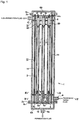
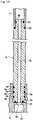
- This separation membrane module 1 is equipped with a cylindrical housing 2 which is disposed with its cylinder axis direction coincident with the top-bottom direction, tubular separation membranes 3 disposed parallel with the axial line of the housing 2, a support plate 5 disposed at the bottom of the housing 2, a bottom cover 6A and a top cover 6B which are attached to the bottom end and the top end of the housing 2, respectively, a first baffle (rectification plate) 7 and a second baffle (rectification plate) 8 which are disposed at a bottom position and a top position, respectively, in the housing 2 parallel with the support plate 5, a pressing plate 25, etc.
- the first baffle 7 is located over the support plate 5.
- flanges 2a, 2b, 6b, and 6c project outward from the bottom end and the top end of the housing 2 and the edges of the outer circumferential portions of the bottom cover 6A and the top cover 6B, respectively, and are fixed together by bolts (not shown).
- a circumferential edge portion of the support plate 5 is held between the flanges 2a and 6b via a gasket (not shown).
- each tubular separation membrane 3 may be replaced by a tubular separation membrane connection body which is formed by connecting two tubular separation membranes 3 by a joint pipe 17.
- a tubular separation membrane connection body which is formed by connecting two tubular separation membranes 3 by a joint pipe 17.
- a multitubular separation membrane module which is equipped with a number of (e.g., 2 to 3,000; preferably 50 to 1,500) tubular separation membranes.
- the outer circumferential surface of the housing 2 is formed with an inlet 9 and an outlet 10 of a processing target fluid at a bottom position and a top position, respectively.
- the inlet 9 is disposed so as to enable access to a room 11 which is formed between the support plate 5 and the first baffle 7.
- the outlet 10 is disposed so as to enable access to a room 12 which is formed over the second baffle 8.
- Amain room 13 for membrane separation is formed between the baffles 7 and 8.
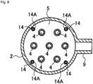
- Plural rods 14 project upward from the bottom support plate 5, and the baffles 7 and 8 and the pressing plate 25 are supported by the rods 14. Bottom end portions of the rods 14 are formed with male screws which are threadedly engaged with female screw holes of the support plate 5, respectively.
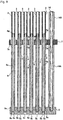
- the baffles 7 and 8 and the pressing plate 25 are supported respectively by sheath pipes 14A, 14B, and 14C (see Figs. 2 and 9 ) which are fitted with the rods 14, so as to be placed at prescribed heights.
- the sheath pipes 14A are disposed between the support plate 5 and the baffle 7.
- the sheath pipes 14B are disposed between the baffles 7 and 8.
- the sheath pipes 14C are disposed between the baffle 8 and the pressing plate 25.
- the baffle 8 is placed on the top end surfaces of the sheath pipes 14B.
- the pressing plate 25 is located over the baffle 8, placed on the top end surfaces of the sheath pipes 14C, and fixed to the top ends of the rods 14 by nuts 14n which are threadedly engaged with top end portions of the rods 14, respectively.
- sealing members such as O-rings, V-packings, or C-rings may be sandwiched between the inner circumferential surface of the housing 2 and the outer circumferential surfaces of the baffles 7 and 8.
- baffles Although in this embodiment the number of baffles is two, three or more baffles may be provided.
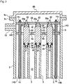
- the baffles 7 and 8 are formed with circular insertion through-holes 7a and 8a for insertion of the tubular separation membranes 3, and connection bodies each of which is formed by connecting a tubular separation membrane 3, an end pipe 4, and an end plug 20 are inserted through the insertion through-holes 7a and 8a.
- the diameters of the insertion through-holes 7a and 8a are larger than the diameters (outer diameters) of the tubular separation membranes 3, the end pipes 4, and the end plugs 20, and hence gaps are formed between the inner circumferential surfaces of the insertion through-holes 7a and 8a and the outer circumferential surfaces of the end pipes 4 and the end plugs 20 over the entire circumferences.
- the top surface of the support plate 5 is formed with insertion holes 5a in which bottom portions of the end pipes 4 which are connected to the tubular separation membranes 3 are inserted.
- the insertion holes 5a are cylindrical and extend from the top surface of the support plate 5 to a halfway position in its thickness direction.
- the bottoms of the insertion holes 5a communicate with the space below the support plate 5 via small holes 5b and large holes 5c, respectively. Sealing between the end pipes 4 and the insertion holes 5a is established by O-rings.
- a pipe hole 4a of each end pipe 4 communicates with, via the small hole 5b and the large hole 5c, an outflow room 16 which is formed by the bottom cover 6A and the support plate 5.
- the bottom cover 6A is provided with an outlet 6a of a separated permeation fluid.
- each end pipe 4 is formed with circumferential grooves 4b in which O-rings 30 made of a fluorine rubber, a fluorine resin, or the like are inserted.
- O-rings 30 made of a fluorine rubber, a fluorine resin, or the like are inserted.
- the plural grooves 4a are formed, only one groove may be formed.
- Sealing between the end pipes 4 and the insertion holes 5a is established by O-rings. More specifically, the bottom end surface of each end pipe 4 is formed with a circumferential groove 4c which is concentric with the pipe hole 4a and in which an O-ring 31 is inserted. Sealing is established between the outer surface of each end pipe 4 and the insertion hole 5a because the O-rings 30 are in close contact with the inner circumferential surface of the insertion hole 5a and the O-ring 31 is in close contact with the bottom surface of the insertion hole 5a. Only one of the set of O-rings 30 in contact with the outer circumferential surface of each end pipe 4 and the O-ring 31 in contact with the bottom end surface of the insertion hole 5a may be provided.
- each end pipe 4 be connected to the support plate 5 in such a manner that an O-ring(s) is inserted in a groove(s) which is formed in at least one of the outer circumferential surface and the end surface of the end pipe and the end pipe which is provided with the O-ring(s) is inserted into the insertion hole.
- each end pipe 4 is shaped into a small-diameter portion 4g which is inserted in a bottom portion of the tubular separation membrane 3. Sealing between the end pipe 4 and the tubular separation membrane 3 is established by O-rings.
- An O-ring 32 is inserted in a circumferential groove which is formed in the outer circumferential surface of the small-diameter portion 4g.
- An O-ring 33 is sandwiched between the bottom end surface of the tubular separation membrane 3 and the step surface of the end pipe 4. Sealing between the end pipe 4 and the tubular separation membranes 3 may be established without using such O-rings; that is, using a heat-shrinkable tube or using both of such O-rings and a heat-shrinkable tube.
- the end plug 20 is connected to a top end portion of each (upper) tubular separation membrane 3.
- the end plug 20, which is cylindrical or has a shape obtained by cutting out portions of a cylinder, seals the tubular separation membrane 3 at its top.
- a bottom end portion of the end plug 20 is formed with a small-diameter portion 21 which is inserted in the tubular separation membrane 3. Sealing between the end plug 20 and the tubular separation membrane 3 is established by O-rings 34 and 35.
- the sealing structure of the end plug 20 and the tubular separation membrane 3 is the same as that of the small-diameter portion 4g of the end pipe 4 and the tubular separation membrane 3. Sealing between the end plug 20 and the tubular separation membranes 3 may be established without using O-rings; that is, using a heat-shrinkable tube or using both of the O-rings and a heat-shrinkable tube.
- each end plug have a rod which projects from its top end surface. More specifically, a rod 22 projects upward from the center of the top end surface of the end plug 20.
- the pressing plate 25 which is located over the end plug 20 is formed with an opening 25a in which the rod 22 is inserted. That is, it is preferable that the pressing plate 25 is opposed to the end plug 20.
- the rod 22 is smaller in diameter than the opening 25a, and hence a gap is formed between the rod 22 and the inner circumferential surface of the opening 25a.
- the diameter of the rod 22 represented by x the diameter of the opening 25a should preferably be longer than or equal to x + 0.02 mm and even preferably be longer than or equal to x + 0.1 mm.
- the diameter of the opening 25a should preferably be shorter than or equal to x + 0.5 mm, much preferably be shorter than or equal to x + 0.4 mm, and far preferably be shorter than or equal to x + 0.2 mm. Where the gap is within this range, the rod 22 can move smoothly and play is unlikely to occur to lower the degree of vibration of the tubular separation membrane 3.
- the separation membrane module is equipped with springs for pushing the end plugs 20 toward the tubular separation membranes.
- a compression coil spring 26 (hereafter may be referred to simply as a "spring 26") is sandwiched between the top end surface of each end plug 20 and the bottom surface of the pressing plate 25 so as to surround the rod 22. The end plug 20 is urged downward by the spring 26. With this measure, the end plug 20 is prevented from coming out even if the internal pressure of the tubular separation membrane 3 is increased due to a certain reason and a force acts on the end plug 20 in such a direction as to cause it to come out of the tubular separation membrane 3. Likewise, the upper tubular separation membrane 3 is prevented from coming out of the joint pipe 17 and the joint pipe 17 is prevented from coming out of the lower tubular separation membrane 3.
- the joint pipe 17 has a through-hole which penetrates through it in its axial direction. Both end portions (top and bottom end portions) of the joint pipe 17 are small-diameter portions which are inserted in the respective tubular separation membranes 3. The outer circumferential surface of each small-diameter portion is formed with a circumferential groove in which an O-ring (not shown) is inserted. Sealing between the joint pipe 17 and each tubular separation membrane 3 may be established without using an O-ring; that is, using a heat-shrinkable tube or using both of the O-ring and a heat-shrinkable tube.
- the portion, between the small-diameter portions as the two end portions of the joint tube 17, of the joint tube 17 is a large-diameter portion and step surfaces are formed between the large-diameter portion and the respective small-diameter portions.
- O-rings (not shown) are also sandwiched between the step surfaces and the end surfaces of the tubular separation membranes 3.
- a baffle be disposed at the position of the joint pipes 17.
- this separation membrane module 1 For example, the end pipes 4, the tubular separation membranes 3 and the end plugs 20 are inserted into the respective insertion holes 5a of the support plate 5 in order so that they project upward from the support plate 5. Air-tight or liquid-tight connection between the support plate 5 and the end pipes 4 can be made easily by merely inserting the bottom end portions of the end pipes 4 into the insertion holes 5a. Since the insertion holes 5a are cylindrical, work of forming the insertion holes 5a of the support plate 5 can be done easily and hence the support plate 5 can be manufactured easily. This contributes to shortening of a manufacturing period of the separation membrane module and reduction of its manufacturing cost.
- a processing target fluid is introduced into the room 11 of the housing 2 through the inlet 9; flows into the main room 13 through the gaps between the inner circumferential surfaces of the insertion through-holes 7a of the baffle 7 and the outer circumferential surfaces of the end pipes 4; goes along the main room 13, and flows into the room 12 through the gaps between the insertion through-holes 8a of the baffle 8 and the end plugs 20.
- the processing target fluid flows along the main room 13, part of its components permeate the tubular separation membrane 3 and are taken out through the outflow room 16 and the outlet 6a. The other part which does not permeate the tubular separation membranes 3 of the components of the fluid flows out of the separation membrane module 1 through the outlet 10.
- each end plug 20 is attached to the top end portion of the tubular separation membrane 3 and urged downward by the spring 26, loads act on the tubular separation membrane 3, the end plug 20, and the end pipe 4 in such directions that they are pressed against each other.
- the degree of sealing between them is high and, as mentioned above, a phenomenon can be prevented that the end plug 20, the tubular separation membrane 3, or the joint pipe 17 comes out when the internal pressure of the tubular separation membrane 3 is increased.
- a flow in the main room 13 and flows in the tubular separation membranes 3 may be in either the same direction or opposite directions, and the inlet 9 and the outlet 10 for a processing target fluid may be interchanged.
- membrane separation can be performed efficiently because a number of tubular separation membrane 3 are arranged parallel with each other and hence the total membrane area is large.
- each tubular separation membrane 3 and each of the end pipe 4 and the end plug 20 is established by the O-rings
- sealing between them can be established by connecting them by a heat-shrinkable tube.
- the springs 26 may be omitted in a case that the interval between the pressing plate 25 and the top end surfaces of the end plugs 20 is small. In this case, when the end plug 20 is moved upward due to increase of the internal pressure of a tubular separation membrane 3, the top end surface of the end plugs 20 hits the pressing plate 25 and is thereby prevented from coming out.
- Fig. 11 is a sectional view of a connection body of tubular separation membranes 3, an end pipe 4, and an end plug 20 according to this embodiment.
- a wire 41 is disposed in the tubular separation membranes 3 and the bottom ends of the wire 41 are connected to the top end surface of the end pipe 4.
- the bottom end of a tension coil spring 42 is connected to the top end of the wire 41.
- a hook 43 is provided at the top end of the tension coil spring 42.
- a hook piece 44 is attached to the bottom end surface of the end plug 20, and the hook 43 is hooked on the hook piece 44.
- the end plug 20 and the end pipe 4 are pulled elastically by pulling forces of the tension coil spring 42, whereby the end plug 20, the tubular separation membranes 3, etc. are prevented from coming out.
- each set of an end plug 20 and a rod 22 is a unitized body, they may be separate bodies.
- This example is shown in Fig. 24 in which each rod 22A has a rod main body 22a which is inserted in the opening 25a, a disc-shaped portion 22b formed at the bottom end of the rod main body 22a, and a coming-off prevention portion 22c formed at the top end of the rod main body 22a.
- the diameter of the rod main body 22a is the same as each rod 22.
- the coming-off prevention portion 22c may be shaped like either a disc or a rod.
- the size of the coming-off prevention portion 22c i.e., the diameter of the disc-shaped coming-off prevention portion 22c or the length of the rod-shaped coming-off prevention portion 22c) is larger than the diameter of the opening 25a, whereby the rod 22A is prevented from passing through the opening 25a and coming off.
- the bottom surface of the coming-off prevention portion 22c is a curved surface that is curved so as to be convex downward.
- the top end surface of the end plug 20A is a convex surface 20r that is curved so as to be concave upward.
- the compression coil spring 26 is sandwiched between the top surface of the disc-shaped portion 22b and the bottom surface of the pressing plate 25 so as to surround the rod main body 22a.
- the spring 26 urges the rod 22A downward and thereby presses its disc-shaped portion 22b against the convex surface 20r. Since the bottom surface of the disc-shaped portion 22b and the convex surface 20r are the above-described curved surfaces, the end plug 20A and the rod 22A come to extend in the vertical direction automatically when the rod 22A is pressed against the end plug 20A and the rod 22A.
- Fig. 12 is a flow diagram of a separation membrane system in which plural separation membrane modules 1 are arranged parallel with each other. Each separation membrane module 1 is installed in the posture shown in Fig. 1 , i.e., the inlet 9 and the outlet 10 are located below and above, respectively.
- a processing target fluid is supplied to the inlets 9 of the respective separation membrane modules 1 via a supply main pipe 50 and plural branch pipes 51, subjected to membrane separation processing, and a permeation fluid is taken out via branch pipes 52 and a collecting pipe 53.
- a non-permeation fluid flows out via branch pipes 54 and a collecting pipe 55.
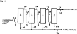
- Fig. 13 is a flow diagram of a separation membrane system in which plural separation membrane modules 1 are connected to each other in series.
- Each separation membrane module 1 is installed in the posture shown in Fig. 1 i.e., the inlet 9 and the outlet 10 are located below and above, respectively.
- a processing target fluid is supplied to the inlet 9 of the most upstream separation membrane module 1 from a supply pipe 56, and a resulting non-permeation fluid is supplied to the inlet 9 of the next-stage separation membrane module 1 via the outlet 10 of the former separation membrane module 1 and a pipe 57.
- a non-permeation fluid which is output from each separation membrane module 1 is supplied to the immediately downstream separation membrane module 1 and a non-permeation fluid which is output from the final-stage separation membrane module 1 flows out of a pipe 58.
- a permeation fluid which has permeated the tubular separation membranes 3 of each separation membrane module 1 is taken out via branch pipes 59 and a collecting pipe 60.
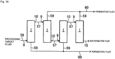
- Fig. 14 shows a separation membrane system in which plural separation membrane modules 1 are connected to each other in series and in which odd-numbered separation membrane modules 1 are installed in the posture shown in Fig. 1 and the even-numbered separation membrane modules 1 are installed in the posture (inverted posture) reverse to the posture shown in Fig. 1 . That is, in each even-numbered separation membrane module 1, the inlet 9 is located at the top of the separation membrane module 1 and the outlet 10 is located at its bottom.
- the other part of the configuration is the same as shown in Fig. 13 , and the manners of flow of a processing target fluid, permeation fluids, and non-permeation fluids are the same as shown in Fig. 13 .
- Fig. 13 In the configuration of Fig.
- each separation membrane module 1 is equipped with the springs 26, the end plugs 20, the tubular separation membranes 3, and the joint pipes 17 are prevented from coming out even if the separation membrane module 1 is installed in the inverted posture.
- a processing target fluid is taken out via the collecting pipe 60
- a modification is possible in which the collecting pipe 60 is omitted and the processing target fluid is taken out via each branch pipe 59.
- the separation membrane module 1 As described above, in the separation membrane module 1 according to the invention, it is possible to input a processing target fluid through the outlet 10 and output a non-permeation fluid through the inlet 9.
- the pipe 57 for guiding a non-permeation fluid from each odd-numbered separation membrane module 1 into the next-stage separation membrane module 1 may be connected to the outlet 10 of the even-numbered separation membrane module 1.
- a separation membrane module has a cylinder-shaped housing and a tubular separation membrane disposed in the housing in which a processing target fluid flows through the housing from its one end side to the other end side and a fluid which has permeated the tubular separation membrane flows through the tubular separation membrane and is taken out, characterized by comprising a vibration absorbing member for the tubular separation membrane.
- the vibration absorbing member be a sheet-like member.
- an end pipe be connected to one end portion of the tubular separation membrane, the end pipe be supported by a support plate that is disposed so as to traverse the housing, an end plug be connected to the other end portion of the tubular separation membrane; and the vibration absorbing member be disposed so as to be in contact with the end plug.
- a pressing plate be provided so as to be opposed to the end plug; the end plug or a rod which projects from the end plug is inserted through an opening of the pressing plate, the vibration absorbing member be disposed on the opposite side of the pressing plate to the tubular separation membrane; and the end plug or the rod is in contact with the vibration absorbing member.
- This separation membrane module 1 is equipped with a cylindrical housing 2, plural tubular separation membranes 3 disposed parallel with the axial line of the housing 2, a support plate 5 disposed at the bottom of the housing 2, a bottom cover 6A and a top cover 6B which are attached to the bottom end and the top end of the housing 2, respectively, a first baffle (rectification plate) 7 and a second baffle (rectification plate) 8 which are disposed at a bottom position and a top position, respectively, in the housing 2 parallel with the support plate 5, a pressing plate 25, etc.
- the first baffle 7 is located over the support plate 5.
- flanges 2a, 2b, 6b, and 6c project outward from the bottom end and the top end of the housing 2 and the edges of the outer circumferential portions of the bottom cover 6A and the top cover 6B, respectively, and are fixed together by bolts (not shown).
- a circumferential edge portion of the support plate 5 is held between the flanges 2a and 6b via a gasket (not shown).
- the separation membrane module 1 can also be used even if it is installed upside down in the cylinder axis direction, i.e., the bottom cover 6A is located above, or it is installed horizontally so that the direction connecting the bottom cover 6A and the top cover 6B is approximately horizontal. This also applies to the other embodiments.
- each tubular separation membrane 3 may be replaced by a tubular separation membrane connection body which is formed by connecting two tubular separation membranes 3 by a joint pipe 17.
- a tubular separation membrane connection body which is formed by connecting two tubular separation membranes 3 by a joint pipe 17.
- a multitubular separation membrane module which is equipped with a number of (e.g., 2 to 3,000; and preferably 50 to 1,500) tubular separation membranes 3.
- the outer circumferential surface of the housing 2 is formed with an inlet 9 and an outlet 10 of a processing target fluid at a bottom position and a top position, respectively.
- the inlet 9 is disposed so as to enable access to a room 11 which is formed between the support plate 5 and the first baffle 7.
- the outlet 10 is disposed so as to enable access to a room 12 which is formed over the second baffle 8.
- a main room 13 for membrane separation is formed between the baffles 7 and 8.
- Plural rods 14 project upward from the bottom support plate 5, and the baffles 7 and 8 and the pressing plate 25 are supported by the rods 14. Bottom end portions of the rods 14 are formed with male screws which are threadedly engaged with female screw holes of the support plate 5, respectively.
- the baffles 7 and 8 and the pressing plate 25 are supported respectively by sheath pipes 14A, 14B, and 14C (see Figs. 4 and 9 ) which are fitted with the rods 14, so as to be placed at prescribed heights.
- the sheath pipes 14A are disposed between the support plate 5 and the baffle 7.
- the sheath pipes 14B are disposed between the baffles 7 and 8.
- the sheath pipes 14C are disposed between the baffle 8 and the pressing plate 25.
- the baffle 8 is placed on the top end surfaces of the sheath pipes 14B.
- the pressing plate 25 is located over the baffle 8, placed on the top end surfaces of the sheath pipes 14C, and fixed to the top ends of the rods 14 by nuts 14n which are threadedly engaged with top end portions of the rods 14, respectively.
- sealing members such as O-rings, V-packings, or C-rings are sandwiched between the inner circumferential surface of the housing 2 and the outer circumferential surfaces of the baffles 7 and 8.
- the baffles 7 and 8 are formed with circular insertion through-holes 7a and 8a for insertion of the tubular separation membranes 3, and connection bodies each of which is formed by connecting a tubular separation membrane 3, an end pipe 4, and an end plug 20 are inserted through the insertion through-holes 7a and 8a.
- the diameters of the insertion through-holes 7a and 8a are larger than the diameters (outer diameters) of the tubular separation membranes 3, the end pipes 4, and the end plugs 20, and hence gaps are formed between the inner circumferential surfaces of the insertion through-holes 7a and 8a and the outer circumferential surfaces of the end pipes 4 and the end plugs 20 over the entire circumferences.
- the number of baffles may be different than in this embodiment, and may be three or more.
- the top surface of the support plate 5 is formed with insertion holes 5a in which bottom portions of the end pipes 4 which are connected to the respective tubular separation membranes 3 are inserted.
- the insertion holes 5a are cylindrical and extend from the top surface of the support plate 5 to a halfway position in its thickness direction.
- the bottoms of the insertion holes 5a communicate with the space below the support plate 5 via small holes 5b and large holes 5c. Sealing between the end pipes 4 and the insertion holes 5a is established by O-rings.
- a pipe hole 4a of each end pipe 4 communicates with, via the small hole 5b and the large hole 5c, an outflow room 16 which is formed by the bottom cover 6A and the support plate 5.
- the bottom cover 6A is provided with an outlet 6a of a separated permeation fluid.
- each end pipe 4 is formed with circumferential grooves 4b in which O-rings 30 made of a fluorine rubber, a fluorine resin, or the like are inserted.
- plural grooves 4a are formed.
- each end pipe 4 Sealing between the end pipes and the insertion holes is established by O-rings. More specifically, the bottom end surface of each end pipe 4 is formed with a circumferential groove 4c which is concentric with the pipe hole 4a and in which an O-ring 31 is inserted. Sealing is established between the outer surface of each end pipe 4 and the insertion hole 5a because the O-rings 30 are in close contact with the inner circumferential surface of the insertion hole 5a and the O-ring 31 is in close contact with the bottom surface of the insertion hole 5a. Only one of the set of O-rings 30 in contact with the outer circumferential surface of each end pipe 4 and the O-ring 31 in contact with the bottom end surface of the insertion hole 5a may be provided.
- the end pipe 4 is connected to the support plate in such a manner that an O-ring(s) is inserted in a groove(s) which is formed in at least one of the outer circumferential surface and the end surface of the end pipe 4 and the end pipe which is provided with the O-ring(s) is inserted into the insertion hole.
- each end pipe 4 is shaped into a small-diameter portion 4g which is inserted in a bottom portion of the tubular separation membrane 3. Sealing between the end pipe 4 and the tubular separation membrane 3 is established by O-rings.
- An O-ring 32 is inserted in a circumferential groove which is formed in the outer circumferential surface of the small-diameter portion 4g.
- An O-ring 33 is sandwiched between the bottom end surface of the tubular separation membrane 3 and the step surface of the end pipe 4. Sealing between the end pipe 4 and the tubular separation membranes 3 may be established without using such O-rings; that is, using a heat-shrinkable tube or using both of such O-rings and a heat-shrinkable tube.
- the end plug 20 is connected to a top end portion of the upper tubular separation membrane 3.
- the end plug 20 which is cylindrical or has a shape obtained by cutting out portions of a cylinder, seals the tubular separation membrane 3 at its top.
- a bottom end portion of the end plug 20 is formed with a small-diameter portion 21 which is inserted in the tubular separation membrane 3. Sealing between the end plug 20 and the tubular separation membrane 3 is established by O-rings 34 and 35.
- the sealing structure of the end plug 20 and the tubular separation membrane 3 is the same as that of the small-diameter portion 4g of the end pipe 4 and the tubular separation membrane 3. Sealing between the end plug 20 and the tubular separation membranes 3 may be established without using O-rings; that is, using a heat-shrinkable tube or using both of the O-rings and a heat-shrinkable tube.
- a rod 22 projects upward from the center of the top end surface of the end plug 20.
- the pressing plate 25 which is located over the end plug 20 is formed with an opening 25a in which the rod 22 is inserted.
- the rod 22 is smaller in diameter than the opening 25a, and hence a gap is formed between the rod 22 and the inner circumferential surface of the opening 25a.
- the circumferential edge of the pressing plate 25 is formed with cuts 25b which allow the room 12 under the pressing plate 25 and a room 12a over the pressing plate 25 to communicate with each other.
- the tubular separation membrane 3 is provided with an absorption absorbing member, which is preferably a sheet-like member.
- the rods 22 somewhat project upward with respect to the pressing plate 25.
- the top surface of the pressing plate 25 is covered with a vibration absorbing sheet 28 which is made of a soft material, and the top end portions of the rods 22 are in contact with the vibration absorbing sheet 28.
- the vibration absorbing sheet 28 is a sheet made of a viscoelastic material such as a gel sheet, a rubber sheet, or a sponge sheet.
- a compression coil spring 26 is sandwiched between the top end surface of the end plug 20 and the bottom surface of the pressing plate 25 so as to surround the rod 22.
- the end plug 20 is urged downward by the spring 26. With this measure, the end plug 20 is prevented from coming out even if the internal pressure of the tubular separation membrane 3 is increased due to a certain reason and a force acts on the end plug 20 in such a direction as to cause it to come out of the tubular separation membrane 3.
- the upper tubular separation membrane 3 is prevented from coming out of the joint pipe 17 and the joint pipe 17 is prevented from coming out of the lower tubular separation membrane 3.
- joint pipes 17 plural (e.g., two) tubular separation membranes 3 are connected to each other by joint pipes 17.
- the joint pipe 17 has a through-hole that penetrates through it in its axial direction. Both end portions (top and bottom end portions) of the joint pipe 17 are small-diameter portions which are inserted in the tubular separation membranes 3.
- the outer circumferential surface of each small-diameter portion is formed with a circumferential groove in which an O-ring (not shown) is inserted. Sealing between the joint pipe 17 and the tubular separation membranes 3 may be established without using an O-ring; that is, using a heat-shrinkable tube or by using both of the O-ring and a heat-shrinkable tube.
- the portion, between the small-diameter portions as the two end portions of the joint tube 17, of the joint tube 17 is a large-diameter portion and step surfaces are formed between the large-diameter portion and the respective small-diameter portions.
- O-rings (not shown) are also sandwiched between the step surfaces and the end surfaces of the tubular separation membranes 3, respectively.
- this separation membrane module For example, the end pipes 4, the tubular separation membranes and the end plugs 20 are inserted into the respective insertion holes 5a of the support plate 5 in order so that they project upward from the support plate 5. Air-tight or liquid-tight connection between the support plate 5 and the end pipes 4 can be made easily by merely inserting the bottom end portions of the end pipes 4 into the insertion holes 5a. Since the insertion holes 5a are cylindrical, work of forming the insertion holes 5a of the support plate 5 can be done easily and hence the support plate 5 can be manufactured easily. This contributes to shortening of a manufacturing period of the separation membrane module and reduction of its manufacturing cost.
- the pressing plate 25 After causing the connection bodies of an end pipe 4, a tubular separation membrane 3, and an end plug 20 to project upward from the support plate 5, the pressing plate 25 is put on with the springs 26 sandwiched between them and the nuts 14n are screwed. Then the pressing plate 25 is covered with the vibration absorbing sheet 28 and the top cover 6B is attached.
- a processing target fluid is introduced into the room 11 of the housing 2 through the inlet 9, flows into the main room 13 through the gaps between the inner circumferential surfaces of the insertion through-holes 7a of the baffle 7 and the outer circumferential surfaces of the end pipes 4, goes along the main room 13, and flows into the room 12 through the gaps between the insertion through-holes 8a of the baffle 8 and the end plugs 20.
- the processing target fluid flows along the main room 13, part of its components permeate the tubular separation membrane 3 and are taken out through the outflow room 16 and the outlet 6a.
- the other part, which is not permeated the tubular separation membranes 3, of the components of the fluid flow out of the separation membrane module 1 through the outlet 10.
- the vibration absorbing member preferably the vibration absorbing sheet 28, is provided, vibration of the tubular separation membranes 3 is prevented, whereby generation of an abnormal sound and early deterioration of the sealing portions, the support bodies, and the tubular separation membranes is prevented. It is preferable that the vibration absorbing member be disposed so as to be in contact with the end plugs 20. In this embodiment, the end pipe 4 and the end plug 20 which are connected to the two respective ends of tubular separation membrane 3 are inserted through the insertion through-holes 7a and 8a of the baffles 7 and 8.
- each end plug 20 is attached to the top end portion of the tubular separation membrane 3 and urged downward by the spring 26, loads act on the tubular separation membrane 3, the end plug 20, the end pipe 4, and the joint pipe 17 in such directions that they are pressed against each other.
- the degree of sealing between them is high and, as mentioned above, a phenomenon can be prevented that the end plug 20, the tubular separation membrane 3, or the joint pipe 17 comes out when the internal pressure of the tubular separation membrane 3 is increased.
- a flow in the main room 13 and flows in the tubular separation membranes 3 may be in either the same direction or opposite directions, and the inlet 9 and the outlet 10 for a processing target fluid may be interchanged.
- membrane separation can be performed efficiently because a number of tubular separation membrane 3 are arranged parallel with each other and hence the total membrane area is large.
- each tubular separation membrane 3 and each of the end pipe 4 and the end plug 20 is established by the O-rings
- sealing between them can be established by connecting them by a heat-shrinkable tube.
- the springs 26 may be omitted in a case that the interval between the pressing plate 25 and the top end surfaces of the end plugs 20 is small. In this case, when the end plug 20 is moved upward due to increase of the internal pressure of a tubular separation membrane 3, the top end surface of the end plugs 20 hits the pressing plate 25 and is thereby prevented from coming out.
- springs which pull the end plugs 20 and the end pipes 4 may be disposed inside the tubular separation membranes 3, respectively.
- the separation membrane module 1 it is possible to input a processing target fluid through the outlet 10 and output a non-permeation fluid through the inlet 9.
- Fig. 16 shows a configuration in which the vibration absorbing sheet 28 is omitted and, instead, ball (spherical body)-like vibration absorbing bodies 40 which are made of a viscoelastic material such as gel, rubber, or sponge are laid on the top surface of the pressing plate 25 so as to surround and be in contact with top end portions of the rods 22.
- the pressing plate 25 is not formed with cuts 25b, it may be formed with cuts 25b.
- the other part of the configuration shown in Fig. 16 is the same as that shown in Fig. 4 , and the same symbols in these drawings denote the same component or portion.
- vibration of the tubular separation membranes 3 is absorbed by the vibration absorbing bodies 40.
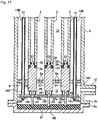
- Fig. 17 shows an example of such a structure.
- Fig. 17 shows a bottom part of a separation membrane module which is configured in such a manner that the separation membrane module shown in Figs. 3 , 4 , and 7-9 is disposed upside down.
- a vibration absorbing sheet 61 is laid on the top cover 6B.
- the vibration absorbing sheet 61 is a viscoelastic member having a prescribed thickness. Bottom end portions of the rods 22 are pushed in the vibration absorbing sheet 61. Vibration of the tubular separation membranes 3 is absorbed by the vibration absorbing sheet 61. That is, it is preferable that the vibration absorbing member be disposed on the opposite side of the pressing plate to the tubular separation membranes and the end plugs or the rods be in contact with the vibration absorbing member.
- the other part of the configuration of the separation membrane module shown in Fig. 17 is the same as that shown in Figs. 3 , 4 , and 7-9 , and the other symbols in Figs. 17 denote the same components or portions as those in Fig. 4 .
- the manner of flow a fluid and the fluid separating operation of the separation membrane module shown in Fig. 17 are the same as those of the separation membrane module 1 shown in Figs. 3 , 4 , and 7-9 .
- the cuts 25b may be omitted.
- Example materials of the end pipes 4 and the end plugs 20 are ones which do not permeate a fluid, such as a metal, a ceramic, and a resin; however, the materials of the end pipes 4 and the end plugs 20 are not limited to them.
- the materials of the baffles 7 and 8 and the joint pipes 17 are ordinarily metal materials such as stainless steel, there are no particular limitations on them except that they should be heat-resistant under separation conditions and resistant to components supplied and permeation components. For certain uses, they may be changed to other materials such as resin materials.
- each tubular separation membrane 3 have a tubular porous support body and a zeolite membrane as an inorganic separation membrane formed on the outer circumferential surface of the porous support body.
- the tubular porous support body are inorganic porous support bodies which are ceramic sintered bodies or metal sintered bodies containing silica, ⁇ -alumina, ⁇ -alumina, mullite, zirconia, titania, yittria, silicon nitride, silicon carbide, etc.
- inorganic porous support bodies containing at least one of alumina, silica, and mullite are preferable. There are no particular limitations on the average pore diameter in the surface of the porous support body.
- the pore diameter be controlled, and that the pore diameter be ordinarily larger than or equal to 0.02 ⁇ m, preferably larger than or equal to 0.05 ⁇ m, and even preferably larger than or equal to 0.1 ⁇ m and be ordinarily smaller than or equal to 20 ⁇ m, preferably smaller than or equal to 10 ⁇ m, and even preferably smaller than or equal to 5 ⁇ m.
- a zeolite membrane is formed on the surface of the porous support body by crystallizing zeolite.
- the zeolite as the main component of the zeolite membrane ordinarily contains zeolite having a 6 to 10-membered oxygen ring structure and preferably contains an 6 to 8-membered oxygen ring structure.
- the parameter n of zeolite having an n-membered oxygen ring means one which is largest in the number of oxygens among pores which are formed by oxygens and T elements which constitute a zeolite framework.
- zeolite having 12-membered oxygen ring pores and 8-membered oxygen ring pores, such as MOR zeolite is regarded as 12-membered oxygen ring zeolite.
- Examples of zeolite having a 6 to 10-membered oxygen ring structure are AEI, AEL, AFG, ANA, BRE, CAS, CDO, CHA, DAC, DDR, DOH, EAB, EPI, ESV, EUO, FAR, FRA, FER, GIS, GIU, GOO, HEU, IMF, ITE, ITH, KFI, LEV, LIO, LOS, LTN, MAR, MEP, MER, MEL, MFI, MFS, MON, MSO, MTF, MTN, MTT, MWW, NAT, NES, NON, PAU, PHI, RHO, RRO, RTE, RTH, RUT, SGT, SOD, STF, STI, STT, TER, TOL, TON, TSC, TUN, UFI, VNI,VSV, WEI, and YUG.
- the zeolite membrane may be any of a membrane made of zeolite only, a membrane formed by dispersing a zeolite powder in a binder such as a polymer, and a zeolite membrane composite body formed by fixing membrane-like zeolite on any of various support bodies.
- the zeolite membrane may contain amorphous components etc. partially.
- the thickness of the zeolite membrane is ordinarily larger than or equal to 0.1 ⁇ m, preferably larger than or equal to 0.6 ⁇ m, and even preferably larger than or equal to 1.0 ⁇ m, and is usually smaller than or equal to 100 ⁇ m, preferably smaller than or equal to 60 ⁇ m, more preferably smaller than or equal to 20 ⁇ m, particularly preferably smaller than or equal to 10 ⁇ m, and most preferably smaller than or equal to 5 ⁇ m.
- tubular separation membranes having a separation membrane other than the zeolite membrane.
- each tubular separation membrane 3 is preferably larger than or equal to 3 mm, much preferably larger than or equal to 6 mm, and far preferably larger than or equal to 10 mm, and is preferably smaller than or equal to 20 mm, more preferably smaller than or equal to 18 mm, and further more preferably smaller than or equal to 16 mm. If the outer diameter is too small, each tubular separation membrane 3 may be insufficient in strength and hence prone to break. If the outer diameter is too large, each tubular separation membrane 3 may be prone to decrease in the membrane area per module.
- each tubular separation membrane 3 is preferably longer than or equal to 20 cm and even preferably shorter than or equal to 200 cm.
- tubular separation membranes In the separation membrane module according to the invention, it is preferable that 1 to 3,000 tubular separation membranes are provided usually, and that the tubular separation membranes are arranged in such a manner that their shortest distance is 2 to 10 mm.
- the size of the housing and the number of tubular separation membranes are changed as appropriate according to the flow amount of a fluid to be processed.
- the joining of tubular separation membranes by a joint pipe 17 is not indispensable.
- the processing target fluid to be separated or condensed there are no particular limitations on the processing target fluid to be separated or condensed, that is, it may be any mixture, except that it should be a gas or liquid mixture consisting of plural components and can be separated or condensed by a separation membrane. However, it is preferable that it is used for a gas mixture.
- the separation or condensation method may be a method called a pervaporation method or a vapor permeation method. Being a separation or condensation method in which a liquid mixture itself is introduced into a separation membrane, the pervaporation method can simplify a process including separation or condensation.
- examples gas mixtures are ones containing at least one component selected from carbon dioxide, oxygen, nitrogen, hydrogen, methane, ethane, ethylene, propane, propylene, normal butane, iso-butane, 1-butene, 2-butene, iso-butene, an aromatic compound such as toluene, sulfur hexafluoride, helium, carbon monoxide, nitrogen monoxide, and water.
- Separation membrane modules according to the invention can be used being connected to each other according to the fluid flow rate or the intended degree of separation or condensation.
- a fluid flow rate or an intended degree of separation or condensation of a processing target fluid is so high that it cannot be processed sufficiently by a single module, it is preferable to make piping so that a fluid which is output from the outlet of one module is supplied to the inlet of another module.
- Even more modules can be connected to each other according to, that is, to attain, an intended degree of separation or condensation.
- a separation membrane module according to a third embodiment of the invention is based on the separation membrane module according to the first or second embodiment in which the end pipe is connected to the one end portion of the tubular separation membrane and the end pipe projects from one plate surface of the support plate which is disposed so as to traverse the housing.
- the separation membrane module is further characterized in that the end pipe is inserted in an insertion hole which is formed in the one plate surface of the support plate, and sealing is established between the end pipe and the insertion hole by an O-ring.
- the O-ring is inserted in a groove which is formed in one of an outer circumferential surface and an end surface of the end pipe, and the end pipe and the support plate be connected to each other by insertion, in the insertion hole, of the end pipe to which the O-ring is attached.
- a separation membrane module according to a fourth embodiment of the invention is based on the separation membrane module according to the first, second, or third embodiment, and is characterized in that the housing is provided with an opening and closing member which can be opened and closed, and a closing member can be attached to a permeation fluid output portion of the tubular separation membrane via the opening and closing member.
- the fluid is a gas mixture.
- the invention also relates to a method for repairing the separation membrane module according to the fourth embodiment.
- the opening and closing member is opened and the closing member is attached to the permeation fluid output portion of the damaged tubular separation membrane.
- a recess 20v is formed so as to extend from the top end surface of the end plug 20. Drain holes may be formed so as to allow a bottom portion of the recess 20v to communicate with the outside of the side circumferential surface of the end plug 20.
- the bottom cover 6A constitutes an opening and closing member and each of "holes" of the support plate 5 is formed by an insertion hole 5a, a small hole 5b, and a large hole 5c.
- the terms "small hole” and “large hole” are used, configurations different than in this embodiment are possible in which the holes 5b and 5c have the same diameter (size) or the hole 5b is larger than the hole 5c.
- a configuration is possible in which the end pipe 4 and the support plate 5 are disposed on the top end side of each tubular separation membrane 3 and the end plug 20 is disposed on the bottom end side of the tubular separation membrane 3.
- an urging member such as a spring for urging the end plug 20 upward so that loads are imposed on the tubular separation membrane 3, the end plug 20, and the end pipe 4 in such directions that their end surfaces are pressed against each other.
- connection bodies of a tubular separation membrane 3, an end pipe 4, and an end plug 20 are caused to project upward from the support plate 5 by inserting the bottom end portion of their end pipes 4 into the insertion holes 5a of the support plate 5.
- Air-tight or liquid-tight connection between the support plate 5 and the end pipes 4 can be made easily by merely inserting the bottom end portions of the end pipes 4 into the insertion holes 5a. Since the insertion holes 5a are cylindrical, work of forming the insertion holes 5a of the support plate 5 can be done easily and hence the support plate 5 can be manufactured easily. This contributes to shortening of a manufacturing period of the separation membrane module and reduction of its manufacturing cost.
- a processing target fluid is introduced into the room 11 of the housing 2 through the inlet 9; flows into the main room 13 through the gaps between the inner circumferential surfaces of the insertion through-holes 7a of the baffle 7 and the outer circumferential surfaces of the end pipes 4; goes along the main room 13; and flows into the room 12 through the gaps between the insertion through-holes 8a of the baffle 8 and the end plugs 20.
- the processing target fluid flows along the main room 13, part of its components permeate the tubular separation membrane 3 and are taken out through the outflow room 16 and the outlet 6a.
- the outlet 6a may be attached not to the bottom cover 6A but to a portion, adjoining the outflow room 16, of the housing.
- a flow in the main room 13 and flows in the tubular separation membranes 3 may be in either the same direction or opposite directions, and the inlet 9 and the outlet 10 for a processing target fluid may be interchanged.
- the separation membrane module 1 can be used with the top cover 6B up. Alternatively, the separation membrane module 1 may be used even if it is used with the bottom cover 6A up. Furthermore, the separation membrane module 1 may be installed horizontally so that the direction connecting the bottom cover 6A and the top cover 6B is approximately horizontal.
- membrane separation can be performed efficiently because a number of tubular separation membrane 3 are arranged parallel with each other and hence the total membrane area is large.
- the end plug 20 and the end pipe 4 which are connected to the two respective ends (top and bottom ends) of each tubular separation membrane 3 are inserted through the insertion through-holes 7a and 8a of the baffles 7 and 8.
- a zeolite membrane is not damaged.
- a stable operation is enabled for a long time.
- a processing target fluid flows into the damaged tubular separation membrane(s) 3 and is mixed with a permeation fluid existing there.
- an opening and closing member which is attached to the housing 2 so as to be openable and closable is opened and the flow of the processing target fluid into the housing 2 is stopped.
- the bottom cover 6A is detached from the housing 2.
- a closing member is inserted into the large hole 5c which communicates with the insertion hole 5a to which the tubular separation membrane 3 is inserted. In this manner, a closing member can be attached to a permeation fluid output portion of each tubular separation membrane via the opening and closing member.
- the separation membrane module can be repaired by opening the opening and closing member and attaching a closing member to the permeation fluid output portion of the damaged tubular separation membrane. Examples of the closing member will be described with reference to Figs. 20(a)-20(d) and 21 .
- a plug-shaped closing member 62 which is made of a soft material such as a rubber or a synthetic resin is pushed into the large hole 5c.
- the side circumferential surface of a portion, to be inserted into the large hole 5c, of the closing member 62 has a saw-tooth-shaped cross section.
- the closing member 62 has such a structure as to be inserted into the large hole 5c easily and not to come out of the large hole 5c easily.
- the rear end of the closing member 62 is formed with a flange 62a. The closing member 62 is pushed into the large hole 5c until the flange 62a comes into close contact with the bottom surface of the support plate 5, whereby pushing of the closing member 62 to a prescribed depth can be confirmed.
- a closing member is composed of a disc-shaped packing 63 which is pushed into the large hole 5c to its deepest position and a screw 64 which is screwed into the large hole 5c by self-tapping.
- the screw 64 is inserted into the large hole 5c and rotated with being pushed strongly, whereby the male threads on the outer circumferential surface of the tip portion of the screw 64 are advanced with being screwed into the inner circumferential surface of the large hole 5c.
- the screw 64 is attached to the large hole 5c.
- the screw 64 is advanced until its head 64a comes into close contact with the bottom surface of the support plate 5, whereby the packing 63 is pressed against the step surface formed at the boundary between the small hole 5b and the large hole 5c.
- a closing member is composed of a packing 63 and a plug 65 made of a metal or the like.
- a small-diameter portion 65a of the plug 65 is inserted and pushed into the large hole 5c until a large-diameter portion 65b reaches the bottom surface of the support plate 5, whereby the packing 63 is pressed against the above-mentioned step surface.
- the large-diameter portion 65b is fixed to the support plate 5 by fastening means 66 such as welding, brazing, or the like.
- a closing member is composed of a packing 36 and a bolt 37.
- the packing 36 is cylindrical and a female screw hole 36a is recessed upward from the bottom end surface of the packing 36.
- the packing 36 is somewhat larger in diameter than the large hole 5c.
- the closing member shown in Fig. 21 is composed of a plug 38 and O-rings 39.
- the outer circumferential surface of the plug 38 is formed with circumferential grooves in which the O-rings 39 are inserted.
- the plug 38 with the O-rings 39 is inserted into the large hole 5c, whereby the O-rings 39 are brought into close contact with the inner circumferential surface of the large hole 5c.
- a flange 38a of the plug 38 is fixed to the bottom surface of the support plate 5 by fastening means 66 such as welding, brazing, or the like.
- the plug 38 may be screwed into the large hole 5c instead of being inserted or sealed with a sealing tape instead of being subjected to welding or brazing.
- Separation membrane modules according to the invention can be used being connected to each other according to the fluid flow amount or the intended degree of separation or condensation.
- a fluid flow amount or an intended degree of separation or condensation of a processing target fluid is so high that it cannot be processed sufficiently by a single module, it is preferable to make piping so that a fluid which is output from the outlet of one module is supplied to the inlet of another module.
- Even more modules can be connected to each other according to, that is, to attain, an intended degree of separation or condensation.
- a system may be constructed in which separation membrane modules according to the invention are installed parallel with each other and a fluid is caused to branch off and resulting gases are supplied to them. Furthermore, modules can be connected in series to the respective modules which are connected to each other in parallel. In this case, since the supply gas rate decreases in the series connection direction and the linear velocity lowers accordingly, it is preferable to decrease the number of modules arranged in parallel to maintain a necessary linear velocity.
- permeation components may be either ejected module by module or ejected together by connecting the modules together.
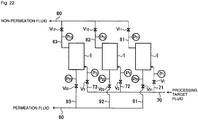
- Fig. 22 is a flow diagram of a membrane separation system in which plural separation membrane modules 1 are arranged parallel with each other.
- a processing target fluid is supplied to the inlets 9 of the separation membrane modules 1 via a pipe 70 and branch pipes 71, 72, and 73, respectively, and non-permeation fluids flow out through the outlets 10 and are output via respective pipes 81, 82, and 83 and a collecting pipe 80.
- Permeation fluids which have permeated the tubular separation membranes 3 of the separation membrane modules 1 flow out through the outlets 6a and are taken out via pipes 91, 92, and 93 and a collecting pipe 90, respectively.
- the branch pipes 71, 72, and 73 for supplying a processing target fluid are provided with valves V 1 , V 2 , and V 3 and pressure sensors P 1 , P 2 , and P 3 , respectively.
- the pipes 81, 82, and 83 are provided with valves V 11 , V 12 , and V 13 and pressure sensors P 11 , P 12 , and P 13 , respectively.
- the permeation fluid pipes 91, 92, and 93 are provided with valves V 21 , V 22 , and V 23 and pressure sensors P 21 , P 22 , and P 23 , respectively.
- valves V 1 -V 3 , V 11 -V 13 , and V 21 -V 23 are kept open.
- the pressure detected by the pressure sensor P 23 for flow out piping of permeation fluids in separation membrane module 1 increases and hence the damaging of this tubular separation membrane is detected.
- the valves V 3 , V 13 , and V 23 are closed, the bottom cover 6A of this tubular separation membrane 3 is detached from the housing 2, and the large hole 5c corresponding to the damaged tubular separation membrane 3 is closed by a closing member.
- the gas existing in this separation membrane module 1 may be replaced by an inert gas or air, if necessary.
- Which tubular separation membrane 3 has been damaged can be judged by opening the valve V 1 , V 2 , or V 3 (the valve V 3 is opened in the case of the leftmost separation membrane module 1) at a small aperture and supplying a processing target fluid to inside the housing 2.
- another gas pressurized gas
- soap liquid is applied to the bottom surface of the support plate 5.
- Which tubular separation membrane 3 has been damaged can be judged from a manner of bursting of a soap liquid film.
- Which tubular separation membrane 3 has been damaged may be judged using smoke from a smoke-generating substance such as incense sticks instead of using a soap liquid film.
- which tubular separation membrane 3 has been damaged may be judged roughly from a sound which is generated when a gas flows out through each large hole 5c.
- a damaged tubular separation membrane 3 may be detected on the basis of membrane permeation difference pressures P 1 - P 21 , P 2 - P 22 , and P 3 - P 23 .
- the pipes 91-93 may be provided with respective gas sensors for detecting a particular component methane, hydrogen, carbon dioxide, or the like instead of or in addition to the respective pressure sensors so that a damaged tubular separation membrane 3 is detected on the basis of variations of the densities of the particular component.
- the invention also relates to a gas mixture separation method of introducing the gas mixture into the separation membrane module and separating a highly permeable gas from the mixture through permeation of the former and a method for manufacturing a high-density gas by introducing a gas mixture into the separation membrane module and producing a high-density gas by separating a highly permeable gas.
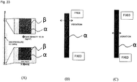
- a porous alumina pipe ⁇ which is sealed on both ends and is 12 mm in outer diameter; 9 mm in inner diameter; and 1,000 mm in length is set at the center in a pipe P which is 18 mm in inner diameter and 1,310 mm in length is set vertically.
- a gas of a pressure 4.2 MPa and a density 52.3 kg/m 3 is caused to flow through the pipe ⁇ from one side from the bottom part at a gas linear velocity 3.5 m/s.
- a manner of gas flow is calculated and it is examined whether the alumina pipe ⁇ is deformed (curved) by a left/right pressure difference which is produced in the alumina pipe ⁇ by the gas flow.
- a gas is caused to flow in a state that the bottom end of the alumina pipe ⁇ is fixed and its top end is set free.
- a gas is caused to flow in a state that both end of the alumina pipe ⁇ are fixed.
Landscapes
- Chemical & Material Sciences (AREA)
- Chemical Kinetics & Catalysis (AREA)
- Engineering & Computer Science (AREA)
- Manufacturing & Machinery (AREA)
- Analytical Chemistry (AREA)
- General Chemical & Material Sciences (AREA)
- Oil, Petroleum & Natural Gas (AREA)
- Separation Using Semi-Permeable Membranes (AREA)
Abstract
Description
- The present invention relates to a separation membrane module used for separating part of the components of a fluid such as a solution or a mixed gas, as well as to a repairing method thereof.
- Separation membrane modules are known as devices for separating components of a solution or a mixed gas. Tubular separation membranes used in separation membrane modules have a tubular porous ceramic support body and a porous separation membrane which is formed on the outer circumferential surface of the support body and made of zeolite or the like. Among methods for separating a particular component from a fluid such as a solution or a mixed gas, a method that a particular component is separated through vaporization by bringing a fluid (solution) into contact with one surface (outer surface) of a separation membrane element with reducing the pressure on the other side (inside); a method that a particular component is separated by vaporizing a solution and bringing a resulting gas into contact with a separation membrane with reducing the pressure on the non-contact side; and a method that a particular component is separated by bringing a mixed gas in a pressurized state into contact with a separation membrane are known (Patent documents 1-3).
-
Patent document 2 discloses a structure that a small-diameter insertion portion of a tubular member is inserted in one end portion of a tubular zeolite separation membrane and sealing is established between the zeolite separation membrane and the tubular member by O-rings made of a fluorine rubber. A processing target fluid is supplied to outside the zeolite separation membrane, and part of its components permeate the zeolite separation membrane and flow into its inside. These components are thus separated from the other components and taken out. -
Patent document 2 also discloses a structure that the zeolite separation membrane and the tubular member butt against each other and the outer circumference of the butting portion is covered with a heat-shrinkable film. -
Patent document 2 further discloses a structure that the tubular member is fixed to a fixing member by screwing and one end portion of the zeolite membrane is fitted with an insertion portion of the tubular member. -
- Patent document 1:
JP-A-2013-39546 - Patent document 2:
JP-A-2011-152507 - Patent document 3:
JP-A-2009-39654 - In the structures of
Patent document 2 that the zeolite separation membrane and the end member are connected to each other by fitting the end member into an end portion of the zeolite separation membrane or they butt against each other with covering with the heat-shrinkable film, a reverse pressure phenomenon that the pressure inside the zeolite separation membrane becomes higher than that outside it may occur for a certain reason. Furthermore, when a force acts on the end member in such a direction as to move it away from the zeolite separation membrane, the end member may come out of the zeolite separation membrane. - A first object of the present invention is to provide a separation membrane module in which an end member is prevented from coming out even at the occurrence of such a reverse pressure or the like.
- In the separation membrane modules disclosed in
Patent documents - A second object of the invention is therefore to provide a separation membrane module in which vibration of a tubular separation membrane is prevented.
- Furthermore, in the method that the tubular member is fixed to the fixing member by screwing, in the case where the number of zeolite separation membranes is large, thread formation work and screwing work take much time and labor, as a result of which a manufacturing period of a separation membrane module becomes long and its manufacturing cost is made high.
- A third object of the invention is therefore to provide a separation membrane module in which an end pipe which is connected to one end portion of a tubular separation membrane can be attached to a support plate easily and the support plate can be manufactured easily.
- Still further, in a separation membrane module in which tubular separation membranes are installed in a housing, if part of the tubular separation membranes e.g., one tubular separation membrane are damaged and a processing target fluid thereby leaks into the secondary side (permeation side), it is a conventional measure wherein supplying the processing target fluid to the separation membrane module is necessary to be stopped to replace the damaged tubular separation membranes. As a result, the operation of the separation membrane module is stopped for a long time.
- A fourth object of the invention is therefore to provide a separation membrane module and its repairing method that make it possible to deal with damaging of part of the tubular separation membranes and restart operation in a short time.
- The summary of the present invention is described below.
- [1] A separation membrane module comprising:
- a cylinder-shaped housing; and
- a tubular separation membrane disposed in the housing, wherein:
- a processing target fluid flows through the housing from its one end side to the other end side and a fluid which has permeated the tubular separation membrane flows through the tubular separation membrane and is taken out;
- an end pipe is connected to one end portion of the tubular separation membrane;
- the end pipe is supported by a support plate which is disposed so as to traverse the housing;
- an end plug is connected to the other end portion of the tubular separation membrane; and
- the separation membrane module further comprises a coming-out preventive member which prevents the end plug from coming out of the tubular separation membrane.
- [2] The separation membrane module according to the above [1], wherein the separation membrane module further comprises, as the coming-out preventive member, a pressing plate which is opposed to the end plug.
- [3] The separation membrane module according to the above [1] or [2], wherein the separation membrane module further comprises, as the coming-out preventive member, a spring which presses the end plug toward the tubular separation membrane.
- [4] The separation membrane module according to the above [1], wherein the separation membrane module further comprises, as the coming-out preventive member, a spring which pulls the end plug and the end pipe toward itself.
- [5] A separation membrane module comprising:
- a cylinder-shaped housing; and
- a tubular separation membrane disposed in the housing, wherein:
- a processing target fluid flows through the housing from its one end side to the other end side and a fluid which has permeated the tubular separation membrane flows through the tubular separation membrane and is taken out;
- an end pipe is connected to one end portion of the tubular separation membrane;
- the end pipe is supported by a support plate which is disposed so as to traverse the housing;
- an end plug is connected to the other end portion of the tubular separation membrane; and
- the end plug has an urging member.
- [6] The separation membrane module according to the above [5], wherein the urging member is at least one of a pressing plate which is opposed to the end plug and a spring which presses the end plug toward the tubular separation membrane or a spring which pulls the end plug and the end pipe toward itself.
- [7] The separation membrane module according to any one of the above [2], [3] and [6], wherein the spring which presses the end plug toward the tubular separation membrane is sandwiched between the pressing plate and the end plug.
- [8] The separation membrane module according to any one of the above [1] to [7], wherein the end plug has a rod which projects from a top end surface of the end plug.
- [9] A separation membrane module comprising:
- a cylinder-shaped housing;
- a tubular separation membrane disposed in the housing; and
- a vibration absorbing member for the tubular separation membrane, wherein:
- a processing target fluid flows through the housing from its one end side to the other end side and a fluid which has permeated the tubular separation membrane flows through the tubular separation membrane and is taken out.
- [10] The separation membrane module according to the above [9], wherein the vibration absorbing member is a sheet-like member.
- [11] The separation membrane module according to the above [9] or [10], wherein:
- an end pipe is connected to one end portion of the tubular separation membrane;
- the end pipe is supported by a support plate which is disposed so as to traverse the housing;
- an end plug is connected to the other end portion of the tubular separation membrane; and
- the vibration absorbing member is disposed so as to be in contact with the end plug.
- [12] The separation membrane module according to the above [11], further comprising a pressing plate which is opposed to the end plug, wherein:
- the end plug or a rod which projects from the end plug is inserted through an opening of the pressing plate; and
- the vibration absorbing member is disposed on the opposite side of the pressing plate to the tubular separation membrane, and the end plug or the rod is in contact with the vibration absorbing member.
- [13] The separation membrane module according to any one of the above [1] to [12], wherein:
- an end pipe is connected to one end portion of the tubular separation membrane;
- the end pipe projects from one plate surface of a support plate which is disposed so as to traverse the housing;
- the end pipe is inserted in an insertion hole which is formed in the one plate surface of the support plate; and
- sealing is established between the end pipe and the insertion hole by an O-ring.
- [14] The separation membrane module according to the above [13], wherein the O-ring is inserted in a groove which is formed in at least one of an outer circumferential surface and an end surface of the end pipe; and
the end pipe and the support plate are connected to each other by insertion, in the insertion hole, of the end pipe to which the O-ring is attached. - [15] The separation membrane module according to any one of the above [1] to [14], wherein:
- the housing is provided with an opening and closing member which can be opened and closed; and
- a closing member can be attached to a permeation fluid output portion of the tubular separation membrane via the opening and closing member.
- [16] The separation membrane module according to any one of the above [1] to [15], wherein the fluid is a gas mixture.
- [17] A method for repairing the separation membrane module according to the above [15] or [16], comprising the steps of:
- opening the opening and closing member of the housing when the separation membrane module has been damaged; and
- attaching the closing member to the permeation fluid output portion of the damaged tubular separation membrane.
- [18] A gas mixture separation method comprising the steps of:
- introducing a gas mixture into the separation membrane module according to any one of the above [1] to [16]; and
- separating a highly permeable gas from the mixture by causing permeation of the former.
- [19] A high-density gas manufacturing method comprising the steps of:
- introducing a gas mixture into the separation membrane module according to any one of the above [1] to [16]; and producing a high-density gas by separating a highly permeable gas.
- In the separation membrane module according to the first mode of the invention, even if a reverse pressure occurs in the tubular separation membrane, the end plug can be prevented from coming out of the tubular separation membrane. Where the coming-out preventing means is formed by the pressing plate and the spring or using the spring which pulls the end plug and the end pipe to itself, a high degree of sealing is established between the tubular separation membrane and the end plug and between the tubular separation membrane and the end pipe.
- In the separation membrane module according to the second mode of the invention, since the vibration absorbing member for absorbing vibration of the tubular separation membrane is provided, vibration of the tubular separation membrane is prevented (or suppressed), whereby generation of an abnormal sound is prevented and the sealing portions, the support body, and the separation membrane module are increased in durability.
- In the separation membrane module according to the third mode of the invention, the end pipe is connected to the support plate by inserting the end pipe into the insertion hole formed in the support plate. This insertion work is very easy. Even a large number of insertion holes can be formed easily. As such, the invention facilitates manufacture of the support plate.
- In the separation membrane module and its repairing method according to the fourth mode of the invention, when part of the tubular separation membranes are damaged, the opening and closing member of the housing is opened and the permeation fluid output portion of each damaged tubular separation membrane is closed by the closing member. This measure prevents a phenomenon that a processing target fluid which leaks into the secondary side of each damaged tubular separation membrane is mixed into a permeation fluid of the other, normal tubular separation membranes.
-
- [
Fig. 1] Fig. 1 is a sectional view, taken by a plane including a housing axial line, of a separation membrane module according to a first embodiment. - [
Fig. 2] Fig. 2 is an enlarged view of a top part ofFig. 1 . - [
Fig. 3] Fig. 3 is a sectional view, taken by a plane including a housing axial line, of a separation membrane module according to a second embodiment. - [
Fig. 4] Fig. 4 is an enlarged view of a top part ofFig. 3 . - [
Fig. 5] Fig. 5 is a sectional view, taken by a plane including a housing axial line, of a separation membrane module according to a third embodiment. - [
Fig. 6] Fig. 6 is a sectional view, taken by a plane including a housing axial line, of a separation membrane module according to a fourth embodiment. - [
Fig. 7] Fig. 7 is a sectional view taken along line III-III inFig. 1 or3 or line II-II inFig. 5 or6 . - [
Fig. 8] Fig. 8 is a sectional view taken along line IV-IV inFig. 1 or3 or line III-III inFig. 5 or6 . - [
Fig. 9] Fig. 9 is an enlarged sectional view of an end pipe and a support plate. - [
Fig. 10] Fig. 10 is an enlarged view of part ofFig. 9 . - [
Fig. 11] Fig. 11 is a sectional view of a tubular separation membrane connection body according to an embodiment relating to the first embodiment. - [
Fig. 12] Fig. 12 is a flow diagram of a separation membrane system. - [
Fig. 13] Fig. 13 is a flow diagram of a separation membrane system. - [
Fig. 14] Fig. 14 is a flow diagram of a separation membrane system. - [
Fig. 15] Fig. 15 is a sectional view, taken by a plane including the housing axial line, of the separation membrane module according to the first embodiment. - [
Fig. 16] Fig. 16 is an enlarged view of a separation membrane module according to an embodiment relating to the second embodiment. - [
Fig. 17] Fig. 17 is an enlarged view of a separation membrane module according to an embodiment relating to the second embodiment. - [
Fig. 18] Fig. 18 is a sectional view, taken by a plane including the housing axial line, of the separation membrane module according to the second embodiment. - [
Fig. 19] Fig. 19 is a sectional view, taken by a plane including the housing axial line, of the separation membrane module according to the third embodiment. - [
Fig. 20] Figs. 20(A)-20(D) are sectional views showing how the separation membrane module according to the fourth embodiment is closed by a closing member. - [
Fig. 21] Fig. 21 is another sectional view showing how the separation membrane module according to the fourth embodiment is closed by a closing member. - [
Fig. 22] Fig. 22 is a flow diagram of a separation membrane system formed by separation membrane modules according to the fourth embodiment. - [
Fig. 23] Fig. 23(A) is a schematic diagram of a system which was used for simulations of Examples,Fig. 23(B) shows a simplified image of an alumina pipe of Referential Example 1, andFig. 23(C) shows a simplified image of an alumina pipe of Referential Example 2. - [
Fig. 24] Fig. 24 is an enlarged sectional view, taken by a plane including a housing axial line, of a top part of a separation membrane module relating to the first embodiment. - A separation membrane module according to a first embodiment of the invention has a cylinder-shaped housing and a tubular separation membrane disposed in the housing in which a processing target fluid flows through the housing from its one end side to the other end side and a fluid which has permeated the tubular separation membrane flows through the tubular separation membrane and is taken out. The separation membrane module is characterized in:
- that an end pipe is connected to one end portion of the tubular separation membrane;
- that the end pipe is supported by a support plate which is disposed so as to traverse the housing;
- that an end plug is connected to the other end portion of the tubular separation membrane; and
- that the separation membrane module comprises a coming-out preventive member which prevents the end plug from coming out of the tubular separation membrane.
- It is preferable that the separation membrane module further comprise, as the coming-out preventive member, at least one of a pressing plate which is opposed to the end plug and a spring which presses the end plug toward the tubular separation membrane or a spring which pulls the end plug and the end pipe toward itself.
- Another separation membrane module according to the first embodiment of the invention has a cylinder-shaped housing and a tubular separation membrane disposed in the housing in which a processing target fluid flows through the housing from its one end side to the other end side and a fluid which has permeated the tubular separation membrane flows through the tubular separation membrane and is taken out. The separation membrane module is characterized in:
- that an end pipe is connected to one end portion of the tubular separation membrane;
- that the end pipe is supported by a support plate which is disposed so as to traverse the housing;
- that an end plug is connected to the other end portion of the tubular separation membrane; and
- that the end plug has an urging member.
- There are no particular limitations on the urging member except that it should be a member which urges the end plug so that it does not come out of the tubular separation membrane. Examples of the urging member are a pressing plate and a spring. More specific examples are at least one of a pressing plate which is opposed to the end plug and a spring which presses the end plug toward the tubular separation membrane, and a spring which pulls the end plug and the end pipe to itself. The urging member is an example of the above-mentioned coming-out preventive member.
- In the above mode, it is preferable that the spring that presses the end plug toward the tubular separation membrane be sandwiched between the pressing plate and the end plug. It is also preferable that the end plug have a rod which projects from a top end surface of the end plug.
- The separation membrane module according to the first embodiment of the invention will be described below with reference to
Figs. 1 ,2 ,7-10 , and15 . However, the scope of the invention is not limited to this. - This
separation membrane module 1 is equipped with acylindrical housing 2 which is disposed with its cylinder axis direction coincident with the top-bottom direction,tubular separation membranes 3 disposed parallel with the axial line of thehousing 2, asupport plate 5 disposed at the bottom of thehousing 2, abottom cover 6A and atop cover 6B which are attached to the bottom end and the top end of thehousing 2, respectively, a first baffle (rectification plate) 7 and a second baffle (rectification plate) 8 which are disposed at a bottom position and a top position, respectively, in thehousing 2 parallel with thesupport plate 5, apressing plate 25, etc. Thefirst baffle 7 is located over thesupport plate 5. - In this embodiment,
flanges housing 2 and the edges of the outer circumferential portions of thebottom cover 6A and thetop cover 6B, respectively, and are fixed together by bolts (not shown). A circumferential edge portion of thesupport plate 5 is held between theflanges - In this embodiment,
end pipes 4 are connected to the bottom ends of thetubular separation membranes 3. End plugs 20 are connected to the top ends of thetubular separation membranes 3. As shown inFig. 15 , eachtubular separation membrane 3 may be replaced by a tubular separation membrane connection body which is formed by connecting twotubular separation membranes 3 by ajoint pipe 17. Although, for example, only seven tubular separation membranes are shown inFigs. 7 and8 , in actuality only onetubular separation membrane 3 may be provided. A further alternative is a multitubular separation membrane module which is equipped with a number of (e.g., 2 to 3,000; preferably 50 to 1,500) tubular separation membranes. - The outer circumferential surface of the
housing 2 is formed with aninlet 9 and anoutlet 10 of a processing target fluid at a bottom position and a top position, respectively. Theinlet 9 is disposed so as to enable access to a room 11 which is formed between thesupport plate 5 and thefirst baffle 7. Theoutlet 10 is disposed so as to enable access to aroom 12 which is formed over thesecond baffle 8.Amain room 13 for membrane separation is formed between thebaffles -
Plural rods 14 project upward from thebottom support plate 5, and thebaffles pressing plate 25 are supported by therods 14. Bottom end portions of therods 14 are formed with male screws which are threadedly engaged with female screw holes of thesupport plate 5, respectively. Thebaffles pressing plate 25 are supported respectively bysheath pipes Figs. 2 and9 ) which are fitted with therods 14, so as to be placed at prescribed heights. Thesheath pipes 14A are disposed between thesupport plate 5 and thebaffle 7. Thesheath pipes 14B are disposed between thebaffles sheath pipes 14C are disposed between thebaffle 8 and thepressing plate 25. Thebaffle 8 is placed on the top end surfaces of thesheath pipes 14B. Thepressing plate 25 is located over thebaffle 8, placed on the top end surfaces of thesheath pipes 14C, and fixed to the top ends of therods 14 by nuts 14n which are threadedly engaged with top end portions of therods 14, respectively. - In this embodiment, sealing members such as O-rings, V-packings, or C-rings may be sandwiched between the inner circumferential surface of the
housing 2 and the outer circumferential surfaces of thebaffles - Although in this embodiment the number of baffles is two, three or more baffles may be provided.
- The
baffles holes tubular separation membranes 3, and connection bodies each of which is formed by connecting atubular separation membrane 3, anend pipe 4, and anend plug 20 are inserted through the insertion through-holes holes tubular separation membranes 3, theend pipes 4, and the end plugs 20, and hence gaps are formed between the inner circumferential surfaces of the insertion through-holes end pipes 4 and the end plugs 20 over the entire circumferences. - The top surface of the
support plate 5 is formed withinsertion holes 5a in which bottom portions of theend pipes 4 which are connected to thetubular separation membranes 3 are inserted. The insertion holes 5a are cylindrical and extend from the top surface of thesupport plate 5 to a halfway position in its thickness direction. The bottoms of theinsertion holes 5a communicate with the space below thesupport plate 5 viasmall holes 5b andlarge holes 5c, respectively. Sealing between theend pipes 4 and theinsertion holes 5a is established by O-rings. - A
pipe hole 4a of eachend pipe 4 communicates with, via thesmall hole 5b and thelarge hole 5c, anoutflow room 16 which is formed by thebottom cover 6A and thesupport plate 5. Thebottom cover 6A is provided with anoutlet 6a of a separated permeation fluid. - As shown in
Fig. 10 , the outer circumferential surface of a portion, close to its bottom end, of eachend pipe 4 is formed withcircumferential grooves 4b in which O-rings 30 made of a fluorine rubber, a fluorine resin, or the like are inserted. Although in this embodiment theplural grooves 4a are formed, only one groove may be formed. - Sealing between the
end pipes 4 and theinsertion holes 5a is established by O-rings. More specifically, the bottom end surface of eachend pipe 4 is formed with acircumferential groove 4c which is concentric with thepipe hole 4a and in which an O-ring 31 is inserted. Sealing is established between the outer surface of eachend pipe 4 and theinsertion hole 5a because the O-rings 30 are in close contact with the inner circumferential surface of theinsertion hole 5a and the O-ring 31 is in close contact with the bottom surface of theinsertion hole 5a. Only one of the set of O-rings 30 in contact with the outer circumferential surface of eachend pipe 4 and the O-ring 31 in contact with the bottom end surface of theinsertion hole 5a may be provided. That is, it is preferable that eachend pipe 4 be connected to thesupport plate 5 in such a manner that an O-ring(s) is inserted in a groove(s) which is formed in at least one of the outer circumferential surface and the end surface of the end pipe and the end pipe which is provided with the O-ring(s) is inserted into the insertion hole. - As shown in
Figs. 9 and10 , a top end portion of eachend pipe 4 is shaped into a small-diameter portion 4g which is inserted in a bottom portion of thetubular separation membrane 3. Sealing between theend pipe 4 and thetubular separation membrane 3 is established by O-rings. An O-ring 32 is inserted in a circumferential groove which is formed in the outer circumferential surface of the small-diameter portion 4g. An O-ring 33 is sandwiched between the bottom end surface of thetubular separation membrane 3 and the step surface of theend pipe 4. Sealing between theend pipe 4 and thetubular separation membranes 3 may be established without using such O-rings; that is, using a heat-shrinkable tube or using both of such O-rings and a heat-shrinkable tube. - As shown in
Figs. 1 and2 , theend plug 20 is connected to a top end portion of each (upper)tubular separation membrane 3. Theend plug 20, which is cylindrical or has a shape obtained by cutting out portions of a cylinder, seals thetubular separation membrane 3 at its top. A bottom end portion of theend plug 20 is formed with a small-diameter portion 21 which is inserted in thetubular separation membrane 3. Sealing between theend plug 20 and thetubular separation membrane 3 is established by O-rings end plug 20 and thetubular separation membrane 3 is the same as that of the small-diameter portion 4g of theend pipe 4 and thetubular separation membrane 3. Sealing between theend plug 20 and thetubular separation membranes 3 may be established without using O-rings; that is, using a heat-shrinkable tube or using both of the O-rings and a heat-shrinkable tube. - It is preferable that each end plug have a rod which projects from its top end surface. More specifically, a
rod 22 projects upward from the center of the top end surface of theend plug 20. Thepressing plate 25 which is located over theend plug 20 is formed with anopening 25a in which therod 22 is inserted. That is, it is preferable that thepressing plate 25 is opposed to theend plug 20. Therod 22 is smaller in diameter than theopening 25a, and hence a gap is formed between therod 22 and the inner circumferential surface of theopening 25a. With the diameter of therod 22 represented by x, the diameter of theopening 25a should preferably be longer than or equal to x + 0.02 mm and even preferably be longer than or equal to x + 0.1 mm. And the diameter of theopening 25a should preferably be shorter than or equal to x + 0.5 mm, much preferably be shorter than or equal to x + 0.4 mm, and far preferably be shorter than or equal to x + 0.2 mm. Where the gap is within this range, therod 22 can move smoothly and play is unlikely to occur to lower the degree of vibration of thetubular separation membrane 3. - It is preferable that the separation membrane module is equipped with springs for pushing the end plugs 20 toward the tubular separation membranes. It is preferable that a compression coil spring 26 (hereafter may be referred to simply as a "
spring 26") is sandwiched between the top end surface of eachend plug 20 and the bottom surface of thepressing plate 25 so as to surround therod 22. The end plug 20 is urged downward by thespring 26. With this measure, theend plug 20 is prevented from coming out even if the internal pressure of thetubular separation membrane 3 is increased due to a certain reason and a force acts on theend plug 20 in such a direction as to cause it to come out of thetubular separation membrane 3. Likewise, the uppertubular separation membrane 3 is prevented from coming out of thejoint pipe 17 and thejoint pipe 17 is prevented from coming out of the lowertubular separation membrane 3. - When each
tubular separation membrane 3 expands or contracts thermally, thespring 26 contracts or expands accordingly. - Where as shown in
Fig. 15 plural (e.g., two)tubular separation membranes 3 are connected to each other byjoint pipes 17, thejoint pipe 17 has a through-hole which penetrates through it in its axial direction. Both end portions (top and bottom end portions) of thejoint pipe 17 are small-diameter portions which are inserted in the respectivetubular separation membranes 3. The outer circumferential surface of each small-diameter portion is formed with a circumferential groove in which an O-ring (not shown) is inserted. Sealing between thejoint pipe 17 and eachtubular separation membrane 3 may be established without using an O-ring; that is, using a heat-shrinkable tube or using both of the O-ring and a heat-shrinkable tube. - The portion, between the small-diameter portions as the two end portions of the
joint tube 17, of thejoint tube 17 is a large-diameter portion and step surfaces are formed between the large-diameter portion and the respective small-diameter portions. O-rings (not shown) are also sandwiched between the step surfaces and the end surfaces of thetubular separation membranes 3. - Although not shown in any drawings, in case of connection by a
joint pipe 17, it is preferable that a baffle be disposed at the position of thejoint pipes 17. - To assemble this
separation membrane module 1, for example, theend pipes 4, thetubular separation membranes 3 and the end plugs 20 are inserted into therespective insertion holes 5a of thesupport plate 5 in order so that they project upward from thesupport plate 5. Air-tight or liquid-tight connection between thesupport plate 5 and theend pipes 4 can be made easily by merely inserting the bottom end portions of theend pipes 4 into theinsertion holes 5a. Since theinsertion holes 5a are cylindrical, work of forming theinsertion holes 5a of thesupport plate 5 can be done easily and hence thesupport plate 5 can be manufactured easily. This contributes to shortening of a manufacturing period of the separation membrane module and reduction of its manufacturing cost. - After causing the connection bodies of an
end pipe 4, atubular separation membrane 3, and anend plug 20 to project upward from thesupport plate 5, thepressing plate 25 is put on theend pipes 4 with thesprings 26 sandwiched between them and the nuts 14n are screwed. Then thetop cover 6B is attached. - In the thus-configured
separation membrane module 1, a processing target fluid is introduced into the room 11 of thehousing 2 through theinlet 9; flows into themain room 13 through the gaps between the inner circumferential surfaces of the insertion through-holes 7a of thebaffle 7 and the outer circumferential surfaces of theend pipes 4; goes along themain room 13, and flows into theroom 12 through the gaps between the insertion through-holes 8a of thebaffle 8 and the end plugs 20. As the processing target fluid flows along themain room 13, part of its components permeate thetubular separation membrane 3 and are taken out through theoutflow room 16 and theoutlet 6a. The other part which does not permeate thetubular separation membranes 3 of the components of the fluid flows out of theseparation membrane module 1 through theoutlet 10. - In this embodiment, since each end plug 20 is attached to the top end portion of the
tubular separation membrane 3 and urged downward by thespring 26, loads act on thetubular separation membrane 3, theend plug 20, and theend pipe 4 in such directions that they are pressed against each other. As a result, the degree of sealing between them is high and, as mentioned above, a phenomenon can be prevented that theend plug 20, thetubular separation membrane 3, or thejoint pipe 17 comes out when the internal pressure of thetubular separation membrane 3 is increased. - A flow in the
main room 13 and flows in thetubular separation membranes 3 may be in either the same direction or opposite directions, and theinlet 9 and theoutlet 10 for a processing target fluid may be interchanged. - In this embodiment, membrane separation can be performed efficiently because a number of
tubular separation membrane 3 are arranged parallel with each other and hence the total membrane area is large. - In this embodiment, the
end pipe 4 and theend plug 20 which are connected to the two respective ends of eachtubular separation membrane 3 are inserted through the insertion through-holes baffles tubular separation membrane 3 is vibrated or swung and theend pipe 4 and theend plug 20 come into contact with the inner circumferential surfaces of the insertion through-holes - Although in the above embodiment sealing between each
tubular separation membrane 3 and each of theend pipe 4 and theend plug 20 is established by the O-rings, sealing between them can be established by connecting them by a heat-shrinkable tube. - Although the above embodiment employs the
springs 26, thesprings 26 may be omitted in a case that the interval between thepressing plate 25 and the top end surfaces of the end plugs 20 is small. In this case, when theend plug 20 is moved upward due to increase of the internal pressure of atubular separation membrane 3, the top end surface of the end plugs 20 hits thepressing plate 25 and is thereby prevented from coming out. - Although in the above embodiment the
springs 26 push the end plugs 20, springs may be used that pull the end plugs 20 and theend pipes 4, respectively. This embodiment will be described with reference toFig. 11 . -
Fig. 11 is a sectional view of a connection body oftubular separation membranes 3, anend pipe 4, and anend plug 20 according to this embodiment. In this connection body, awire 41 is disposed in thetubular separation membranes 3 and the bottom ends of thewire 41 are connected to the top end surface of theend pipe 4. The bottom end of atension coil spring 42 is connected to the top end of thewire 41. Ahook 43 is provided at the top end of thetension coil spring 42. Ahook piece 44 is attached to the bottom end surface of theend plug 20, and thehook 43 is hooked on thehook piece 44. Theend plug 20 and theend pipe 4 are pulled elastically by pulling forces of thetension coil spring 42, whereby theend plug 20, thetubular separation membranes 3, etc. are prevented from coming out. - Although in the above embodiment each set of an
end plug 20 and arod 22 is a unitized body, they may be separate bodies. This example is shown inFig. 24 in which eachrod 22A has a rodmain body 22a which is inserted in theopening 25a, a disc-shapedportion 22b formed at the bottom end of the rodmain body 22a, and a coming-off prevention portion 22c formed at the top end of the rodmain body 22a. The diameter of the rodmain body 22a is the same as eachrod 22. The coming-off prevention portion 22c may be shaped like either a disc or a rod. The size of the coming-off prevention portion 22c (i.e., the diameter of the disc-shaped coming-off prevention portion 22c or the length of the rod-shaped coming-off prevention portion 22c) is larger than the diameter of theopening 25a, whereby therod 22A is prevented from passing through theopening 25a and coming off. - In this embodiment, the bottom surface of the coming-
off prevention portion 22c is a curved surface that is curved so as to be convex downward. The top end surface of theend plug 20A is aconvex surface 20r that is curved so as to be concave upward. - The
compression coil spring 26 is sandwiched between the top surface of the disc-shapedportion 22b and the bottom surface of thepressing plate 25 so as to surround the rodmain body 22a. Thespring 26 urges therod 22A downward and thereby presses its disc-shapedportion 22b against theconvex surface 20r. Since the bottom surface of the disc-shapedportion 22b and theconvex surface 20r are the above-described curved surfaces, the end plug 20A and therod 22A come to extend in the vertical direction automatically when therod 22A is pressed against the end plug 20A and therod 22A. - The other part of the configuration shown in
Fig. 24 is the same as that shown inFig. 2 , and the same symbols in these drawings denote the same component or portion. - Example configurations of separation membrane systems using plural
separation membrane modules 1 will be described with reference toFigs. 12-14 . -
Fig. 12 is a flow diagram of a separation membrane system in which pluralseparation membrane modules 1 are arranged parallel with each other. Eachseparation membrane module 1 is installed in the posture shown inFig. 1 , i.e., theinlet 9 and theoutlet 10 are located below and above, respectively. A processing target fluid is supplied to theinlets 9 of the respectiveseparation membrane modules 1 via a supplymain pipe 50 andplural branch pipes 51, subjected to membrane separation processing, and a permeation fluid is taken out viabranch pipes 52 and a collectingpipe 53. A non-permeation fluid flows out viabranch pipes 54 and a collectingpipe 55. - In this separation membrane system, if
tubular separation membrane 3 of a part of theseparation membrane modules 1 is damaged and a processing target fluid directly flows into thistubular separation membrane 3 through a damaged portion, the inner pressure of the damagedtubular separation membrane 3 of theseparation membrane module 1 is increased and the inner pressures of thetubular separation membranes 3 of the otherseparation membrane modules 1 are also increased via thebranch pipes 54 and the collectingpipe 55. - In this embodiment, even in the event of such a reverse pressure phenomenon, as described above, the end plugs 20 etc. of each
separation membrane module 1 do not come out. -
Fig. 13 is a flow diagram of a separation membrane system in which pluralseparation membrane modules 1 are connected to each other in series. Eachseparation membrane module 1 is installed in the posture shown inFig. 1 i.e., theinlet 9 and theoutlet 10 are located below and above, respectively. A processing target fluid is supplied to theinlet 9 of the most upstreamseparation membrane module 1 from asupply pipe 56, and a resulting non-permeation fluid is supplied to theinlet 9 of the next-stageseparation membrane module 1 via theoutlet 10 of the formerseparation membrane module 1 and apipe 57. Likewise, a non-permeation fluid which is output from eachseparation membrane module 1 is supplied to the immediately downstreamseparation membrane module 1 and a non-permeation fluid which is output from the final-stageseparation membrane module 1 flows out of apipe 58. A permeation fluid which has permeated thetubular separation membranes 3 of eachseparation membrane module 1 is taken out viabranch pipes 59 and a collectingpipe 60. -
Fig. 14 shows a separation membrane system in which pluralseparation membrane modules 1 are connected to each other in series and in which odd-numberedseparation membrane modules 1 are installed in the posture shown inFig. 1 and the even-numberedseparation membrane modules 1 are installed in the posture (inverted posture) reverse to the posture shown inFig. 1 . That is, in each even-numberedseparation membrane module 1, theinlet 9 is located at the top of theseparation membrane module 1 and theoutlet 10 is located at its bottom. The other part of the configuration is the same as shown inFig. 13 , and the manners of flow of a processing target fluid, permeation fluids, and non-permeation fluids are the same as shown inFig. 13 . In the configuration ofFig. 14 , the length of eachpipe 57 can be shorter than in the configuration ofFig. 13 . Since eachseparation membrane module 1 is equipped with thesprings 26, the end plugs 20, thetubular separation membranes 3, and thejoint pipes 17 are prevented from coming out even if theseparation membrane module 1 is installed in the inverted posture. - In
Figs. 13 and14 , a processing target fluid is taken out via the collectingpipe 60, a modification is possible in which the collectingpipe 60 is omitted and the processing target fluid is taken out via eachbranch pipe 59. - As described above, in the
separation membrane module 1 according to the invention, it is possible to input a processing target fluid through theoutlet 10 and output a non-permeation fluid through theinlet 9. Thus, in the configuration ofFig. 13 , thepipe 57 for guiding a non-permeation fluid from each odd-numberedseparation membrane module 1 into the next-stage separation membrane module 1 (even-numbered separation membrane module 1) may be connected to theoutlet 10 of the even-numberedseparation membrane module 1. - A separation membrane module according to a second embodiment of the invention has a cylinder-shaped housing and a tubular separation membrane disposed in the housing in which a processing target fluid flows through the housing from its one end side to the other end side and a fluid which has permeated the tubular separation membrane flows through the tubular separation membrane and is taken out, characterized by comprising a vibration absorbing member for the tubular separation membrane.
- In the above mode, it is preferable that the vibration absorbing member be a sheet-like member.
- It is preferable that an end pipe be connected to one end portion of the tubular separation membrane, the end pipe be supported by a support plate that is disposed so as to traverse the housing, an end plug be connected to the other end portion of the tubular separation membrane; and the vibration absorbing member be disposed so as to be in contact with the end plug. It is even preferable that a pressing plate be provided so as to be opposed to the end plug; the end plug or a rod which projects from the end plug is inserted through an opening of the pressing plate, the vibration absorbing member be disposed on the opposite side of the pressing plate to the tubular separation membrane; and the end plug or the rod is in contact with the vibration absorbing member.
- The separation membrane module according to the second embodiment of the invention will be described below with reference to
Figs. 3 ,4 ,7-10 , and18 . However, the scope of the invention is not limited to this. - This
separation membrane module 1 is equipped with acylindrical housing 2, pluraltubular separation membranes 3 disposed parallel with the axial line of thehousing 2, asupport plate 5 disposed at the bottom of thehousing 2, abottom cover 6A and atop cover 6B which are attached to the bottom end and the top end of thehousing 2, respectively, a first baffle (rectification plate) 7 and a second baffle (rectification plate) 8 which are disposed at a bottom position and a top position, respectively, in thehousing 2 parallel with thesupport plate 5, apressing plate 25, etc. Thefirst baffle 7 is located over thesupport plate 5. - In this embodiment,
flanges housing 2 and the edges of the outer circumferential portions of thebottom cover 6A and thetop cover 6B, respectively, and are fixed together by bolts (not shown). A circumferential edge portion of thesupport plate 5 is held between theflanges - The
separation membrane module 1 can also be used even if it is installed upside down in the cylinder axis direction, i.e., thebottom cover 6A is located above, or it is installed horizontally so that the direction connecting thebottom cover 6A and thetop cover 6B is approximately horizontal. This also applies to the other embodiments. - In this embodiment,
end pipes 4 are connected to the bottom ends of thetubular separation membranes 3. End plugs 20 are connected to the top ends of thetubular separation membranes 3. As shown inFig. 18 , eachtubular separation membrane 3 may be replaced by a tubular separation membrane connection body which is formed by connecting twotubular separation membranes 3 by ajoint pipe 17. Although, for example, only seventubular separation membranes 3 are shown inFigs. 7 and8 , actually, only onetubular separation membrane 3 may be provided. A further alternative is a multitubular separation membrane module which is equipped with a number of (e.g., 2 to 3,000; and preferably 50 to 1,500)tubular separation membranes 3. - The outer circumferential surface of the
housing 2 is formed with aninlet 9 and anoutlet 10 of a processing target fluid at a bottom position and a top position, respectively. Theinlet 9 is disposed so as to enable access to a room 11 which is formed between thesupport plate 5 and thefirst baffle 7. Theoutlet 10 is disposed so as to enable access to aroom 12 which is formed over thesecond baffle 8. Amain room 13 for membrane separation is formed between thebaffles -
Plural rods 14 project upward from thebottom support plate 5, and thebaffles pressing plate 25 are supported by therods 14. Bottom end portions of therods 14 are formed with male screws which are threadedly engaged with female screw holes of thesupport plate 5, respectively. Thebaffles pressing plate 25 are supported respectively bysheath pipes Figs. 4 and9 ) which are fitted with therods 14, so as to be placed at prescribed heights. Thesheath pipes 14A are disposed between thesupport plate 5 and thebaffle 7. Thesheath pipes 14B are disposed between thebaffles sheath pipes 14C are disposed between thebaffle 8 and thepressing plate 25. Thebaffle 8 is placed on the top end surfaces of thesheath pipes 14B. Thepressing plate 25 is located over thebaffle 8, placed on the top end surfaces of thesheath pipes 14C, and fixed to the top ends of therods 14 by nuts 14n which are threadedly engaged with top end portions of therods 14, respectively. - In this embodiment, sealing members such as O-rings, V-packings, or C-rings are sandwiched between the inner circumferential surface of the
housing 2 and the outer circumferential surfaces of thebaffles - The
baffles holes tubular separation membranes 3, and connection bodies each of which is formed by connecting atubular separation membrane 3, anend pipe 4, and anend plug 20 are inserted through the insertion through-holes holes tubular separation membranes 3, theend pipes 4, and the end plugs 20, and hence gaps are formed between the inner circumferential surfaces of the insertion through-holes end pipes 4 and the end plugs 20 over the entire circumferences. The number of baffles may be different than in this embodiment, and may be three or more. - The top surface of the
support plate 5 is formed withinsertion holes 5a in which bottom portions of theend pipes 4 which are connected to the respectivetubular separation membranes 3 are inserted. The insertion holes 5a are cylindrical and extend from the top surface of thesupport plate 5 to a halfway position in its thickness direction. The bottoms of theinsertion holes 5a communicate with the space below thesupport plate 5 viasmall holes 5b andlarge holes 5c. Sealing between theend pipes 4 and theinsertion holes 5a is established by O-rings. - A
pipe hole 4a of eachend pipe 4 communicates with, via thesmall hole 5b and thelarge hole 5c, anoutflow room 16 which is formed by thebottom cover 6A and thesupport plate 5. Thebottom cover 6A is provided with anoutlet 6a of a separated permeation fluid. - As shown in
Fig. 10 , the outer circumferential surface of a portion, close to its bottom end, of eachend pipe 4 is formed withcircumferential grooves 4b in which O-rings 30 made of a fluorine rubber, a fluorine resin, or the like are inserted. In this embodiment,plural grooves 4a are formed. - Sealing between the end pipes and the insertion holes is established by O-rings. More specifically, the bottom end surface of each
end pipe 4 is formed with acircumferential groove 4c which is concentric with thepipe hole 4a and in which an O-ring 31 is inserted. Sealing is established between the outer surface of eachend pipe 4 and theinsertion hole 5a because the O-rings 30 are in close contact with the inner circumferential surface of theinsertion hole 5a and the O-ring 31 is in close contact with the bottom surface of theinsertion hole 5a. Only one of the set of O-rings 30 in contact with the outer circumferential surface of eachend pipe 4 and the O-ring 31 in contact with the bottom end surface of theinsertion hole 5a may be provided. That is, it is preferable that theend pipe 4 is connected to the support plate in such a manner that an O-ring(s) is inserted in a groove(s) which is formed in at least one of the outer circumferential surface and the end surface of theend pipe 4 and the end pipe which is provided with the O-ring(s) is inserted into the insertion hole. - As shown in
Figs. 9 and10 , a top end portion of eachend pipe 4 is shaped into a small-diameter portion 4g which is inserted in a bottom portion of thetubular separation membrane 3. Sealing between theend pipe 4 and thetubular separation membrane 3 is established by O-rings. An O-ring 32 is inserted in a circumferential groove which is formed in the outer circumferential surface of the small-diameter portion 4g. An O-ring 33 is sandwiched between the bottom end surface of thetubular separation membrane 3 and the step surface of theend pipe 4. Sealing between theend pipe 4 and thetubular separation membranes 3 may be established without using such O-rings; that is, using a heat-shrinkable tube or using both of such O-rings and a heat-shrinkable tube. - As shown in
Figs. 3 and4 , theend plug 20 is connected to a top end portion of the uppertubular separation membrane 3. Theend plug 20, which is cylindrical or has a shape obtained by cutting out portions of a cylinder, seals thetubular separation membrane 3 at its top. A bottom end portion of theend plug 20 is formed with a small-diameter portion 21 which is inserted in thetubular separation membrane 3. Sealing between theend plug 20 and thetubular separation membrane 3 is established by O-rings end plug 20 and thetubular separation membrane 3 is the same as that of the small-diameter portion 4g of theend pipe 4 and thetubular separation membrane 3. Sealing between theend plug 20 and thetubular separation membranes 3 may be established without using O-rings; that is, using a heat-shrinkable tube or using both of the O-rings and a heat-shrinkable tube. - A
rod 22 projects upward from the center of the top end surface of theend plug 20. Thepressing plate 25 which is located over theend plug 20 is formed with anopening 25a in which therod 22 is inserted. Therod 22 is smaller in diameter than theopening 25a, and hence a gap is formed between therod 22 and the inner circumferential surface of theopening 25a. - The circumferential edge of the
pressing plate 25 is formed withcuts 25b which allow theroom 12 under thepressing plate 25 and aroom 12a over thepressing plate 25 to communicate with each other. - The
tubular separation membrane 3 is provided with an absorption absorbing member, which is preferably a sheet-like member. For example, therods 22 somewhat project upward with respect to thepressing plate 25. The top surface of thepressing plate 25 is covered with avibration absorbing sheet 28 which is made of a soft material, and the top end portions of therods 22 are in contact with thevibration absorbing sheet 28. Thevibration absorbing sheet 28 is a sheet made of a viscoelastic material such as a gel sheet, a rubber sheet, or a sponge sheet. - A
compression coil spring 26 is sandwiched between the top end surface of theend plug 20 and the bottom surface of thepressing plate 25 so as to surround therod 22. The end plug 20 is urged downward by thespring 26. With this measure, theend plug 20 is prevented from coming out even if the internal pressure of thetubular separation membrane 3 is increased due to a certain reason and a force acts on theend plug 20 in such a direction as to cause it to come out of thetubular separation membrane 3. Likewise, the uppertubular separation membrane 3 is prevented from coming out of thejoint pipe 17 and thejoint pipe 17 is prevented from coming out of the lowertubular separation membrane 3. - When each
tubular separation membrane 3 expends or contracts thermally, thespring 26 contracts or expands accordingly. - As described above, in the embodiment shown in
Fig. 18 , plural (e.g., two)tubular separation membranes 3 are connected to each other byjoint pipes 17. Thejoint pipe 17 has a through-hole that penetrates through it in its axial direction. Both end portions (top and bottom end portions) of thejoint pipe 17 are small-diameter portions which are inserted in thetubular separation membranes 3. The outer circumferential surface of each small-diameter portion is formed with a circumferential groove in which an O-ring (not shown) is inserted. Sealing between thejoint pipe 17 and thetubular separation membranes 3 may be established without using an O-ring; that is, using a heat-shrinkable tube or by using both of the O-ring and a heat-shrinkable tube. - The portion, between the small-diameter portions as the two end portions of the
joint tube 17, of thejoint tube 17 is a large-diameter portion and step surfaces are formed between the large-diameter portion and the respective small-diameter portions. O-rings (not shown) are also sandwiched between the step surfaces and the end surfaces of thetubular separation membranes 3, respectively. - To assemble this
separation membrane module 1, for example, theend pipes 4, the tubular separation membranes and the end plugs 20 are inserted into therespective insertion holes 5a of thesupport plate 5 in order so that they project upward from thesupport plate 5. Air-tight or liquid-tight connection between thesupport plate 5 and theend pipes 4 can be made easily by merely inserting the bottom end portions of theend pipes 4 into theinsertion holes 5a. Since theinsertion holes 5a are cylindrical, work of forming theinsertion holes 5a of thesupport plate 5 can be done easily and hence thesupport plate 5 can be manufactured easily. This contributes to shortening of a manufacturing period of the separation membrane module and reduction of its manufacturing cost. - After causing the connection bodies of an
end pipe 4, atubular separation membrane 3, and anend plug 20 to project upward from thesupport plate 5, thepressing plate 25 is put on with thesprings 26 sandwiched between them and the nuts 14n are screwed. Then thepressing plate 25 is covered with thevibration absorbing sheet 28 and thetop cover 6B is attached. - In the thus-configured
separation membrane module 1, a processing target fluid is introduced into the room 11 of thehousing 2 through theinlet 9, flows into themain room 13 through the gaps between the inner circumferential surfaces of the insertion through-holes 7a of thebaffle 7 and the outer circumferential surfaces of theend pipes 4, goes along themain room 13, and flows into theroom 12 through the gaps between the insertion through-holes 8a of thebaffle 8 and the end plugs 20. As the processing target fluid flows along themain room 13, part of its components permeate thetubular separation membrane 3 and are taken out through theoutflow room 16 and theoutlet 6a. The other part, which is not permeated thetubular separation membranes 3, of the components of the fluid flow out of theseparation membrane module 1 through theoutlet 10. - In this embodiment, since the vibration absorbing member, preferably the
vibration absorbing sheet 28, is provided, vibration of thetubular separation membranes 3 is prevented, whereby generation of an abnormal sound and early deterioration of the sealing portions, the support bodies, and the tubular separation membranes is prevented. It is preferable that the vibration absorbing member be disposed so as to be in contact with the end plugs 20. In this embodiment, theend pipe 4 and theend plug 20 which are connected to the two respective ends oftubular separation membrane 3 are inserted through the insertion through-holes baffles tubular separation membrane 3 is vibrated or swung and theend pipe 4 and theend plug 20 come into contact with the inner circumferential surfaces of the insertion through-holes - In this embodiment, since each end plug 20 is attached to the top end portion of the
tubular separation membrane 3 and urged downward by thespring 26, loads act on thetubular separation membrane 3, theend plug 20, theend pipe 4, and thejoint pipe 17 in such directions that they are pressed against each other. As a result, the degree of sealing between them is high and, as mentioned above, a phenomenon can be prevented that theend plug 20, thetubular separation membrane 3, or thejoint pipe 17 comes out when the internal pressure of thetubular separation membrane 3 is increased. - A flow in the
main room 13 and flows in thetubular separation membranes 3 may be in either the same direction or opposite directions, and theinlet 9 and theoutlet 10 for a processing target fluid may be interchanged. - In this embodiment, membrane separation can be performed efficiently because a number of
tubular separation membrane 3 are arranged parallel with each other and hence the total membrane area is large. - Although in this embodiment sealing between each
tubular separation membrane 3 and each of theend pipe 4 and theend plug 20 is established by the O-rings, sealing between them can be established by connecting them by a heat-shrinkable tube. - Although the above embodiment employs the
springs 26, thesprings 26 may be omitted in a case that the interval between thepressing plate 25 and the top end surfaces of the end plugs 20 is small. In this case, when theend plug 20 is moved upward due to increase of the internal pressure of atubular separation membrane 3, the top end surface of the end plugs 20 hits thepressing plate 25 and is thereby prevented from coming out. - Although in the above embodiment the
springs 26 push the end plugs 20, springs which pull the end plugs 20 and theend pipes 4 may be disposed inside thetubular separation membranes 3, respectively. - In the
separation membrane module 1 according to the invention, it is possible to input a processing target fluid through theoutlet 10 and output a non-permeation fluid through theinlet 9. - Although the above embodiment employs the
vibration absorbing sheet 28 as the vibration absorbing member, another kind of vibration absorbing member may be employed as exemplified inFig. 16 . -
Fig. 16 shows a configuration in which thevibration absorbing sheet 28 is omitted and, instead, ball (spherical body)-likevibration absorbing bodies 40 which are made of a viscoelastic material such as gel, rubber, or sponge are laid on the top surface of thepressing plate 25 so as to surround and be in contact with top end portions of therods 22. Although thepressing plate 25 is not formed withcuts 25b, it may be formed withcuts 25b. The other part of the configuration shown inFig. 16 is the same as that shown inFig. 4 , and the same symbols in these drawings denote the same component or portion. Also in this embodiment, vibration of thetubular separation membranes 3 is absorbed by thevibration absorbing bodies 40. - Although the above embodiment employs the configuration that the
tubular separation membranes 3 project upward from thesupport plate 5, another configuration is possible in which a support plate is disposed above in a separation membrane module and tubular separation membranes hang from the support plate.Fig. 17 shows an example of such a structure. -
Fig. 17 shows a bottom part of a separation membrane module which is configured in such a manner that the separation membrane module shown inFigs. 3 ,4 , and7-9 is disposed upside down. In this separation membrane module, avibration absorbing sheet 61 is laid on thetop cover 6B. Thevibration absorbing sheet 61 is a viscoelastic member having a prescribed thickness. Bottom end portions of therods 22 are pushed in thevibration absorbing sheet 61. Vibration of thetubular separation membranes 3 is absorbed by thevibration absorbing sheet 61. That is, it is preferable that the vibration absorbing member be disposed on the opposite side of the pressing plate to the tubular separation membranes and the end plugs or the rods be in contact with the vibration absorbing member. - The other part of the configuration of the separation membrane module shown in
Fig. 17 is the same as that shown inFigs. 3 ,4 , and7-9 , and the other symbols inFigs. 17 denote the same components or portions as those inFig. 4 . The manner of flow a fluid and the fluid separating operation of the separation membrane module shown inFig. 17 are the same as those of theseparation membrane module 1 shown inFigs. 3 ,4 , and7-9 . Thecuts 25b may be omitted. - Although in each of the above embodiments thin-rod-
like rods 22 project from the respective end plugs 20, another configuration is possible in which therods 22 are omitted and theopenings 25a are made so large that tip portions themselves of the end plugs 20 can be inserted into theopenings 25a. - Materials etc. suitable for the individual members constituting the separation membrane module according to the invention will be described below.
- Example materials of the
end pipes 4 and the end plugs 20 are ones which do not permeate a fluid, such as a metal, a ceramic, and a resin; however, the materials of theend pipes 4 and the end plugs 20 are not limited to them. Although the materials of thebaffles joint pipes 17 are ordinarily metal materials such as stainless steel, there are no particular limitations on them except that they should be heat-resistant under separation conditions and resistant to components supplied and permeation components. For certain uses, they may be changed to other materials such as resin materials. - It is preferable that each
tubular separation membrane 3 have a tubular porous support body and a zeolite membrane as an inorganic separation membrane formed on the outer circumferential surface of the porous support body. Examples of the tubular porous support body are inorganic porous support bodies which are ceramic sintered bodies or metal sintered bodies containing silica, α-alumina, γ-alumina, mullite, zirconia, titania, yittria, silicon nitride, silicon carbide, etc. Among them, inorganic porous support bodies containing at least one of alumina, silica, and mullite are preferable. There are no particular limitations on the average pore diameter in the surface of the porous support body. However, it is preferable that the pore diameter be controlled, and that the pore diameter be ordinarily larger than or equal to 0.02 µm, preferably larger than or equal to 0.05 µm, and even preferably larger than or equal to 0.1 µm and be ordinarily smaller than or equal to 20 µm, preferably smaller than or equal to 10 µm, and even preferably smaller than or equal to 5 µm. - A zeolite membrane is formed on the surface of the porous support body by crystallizing zeolite. The zeolite as the main component of the zeolite membrane ordinarily contains zeolite having a 6 to 10-membered oxygen ring structure and preferably contains an 6 to 8-membered oxygen ring structure.
- The parameter n of zeolite having an n-membered oxygen ring means one which is largest in the number of oxygens among pores which are formed by oxygens and T elements which constitute a zeolite framework. For example, where zeolite having 12-membered oxygen ring pores and 8-membered oxygen ring pores, such as MOR zeolite, is regarded as 12-membered oxygen ring zeolite.
- Examples of zeolite having a 6 to 10-membered oxygen ring structure are AEI, AEL, AFG, ANA, BRE, CAS, CDO, CHA, DAC, DDR, DOH, EAB, EPI, ESV, EUO, FAR, FRA, FER, GIS, GIU, GOO, HEU, IMF, ITE, ITH, KFI, LEV, LIO, LOS, LTN, MAR, MEP, MER, MEL, MFI, MFS, MON, MSO, MTF, MTN, MTT, MWW, NAT, NES, NON, PAU, PHI, RHO, RRO, RTE, RTH, RUT, SGT, SOD, STF, STI, STT, TER, TOL, TON, TSC, TUN, UFI, VNI,VSV, WEI, and YUG.
- The zeolite membrane may be any of a membrane made of zeolite only, a membrane formed by dispersing a zeolite powder in a binder such as a polymer, and a zeolite membrane composite body formed by fixing membrane-like zeolite on any of various support bodies. The zeolite membrane may contain amorphous components etc. partially.
- There is no particular limitation for the thickness of the zeolite membrane. However, the zeolite membrane thickness is ordinarily larger than or equal to 0.1 µm, preferably larger than or equal to 0.6 µm, and even preferably larger than or equal to 1.0 µm, and is usually smaller than or equal to 100 µm, preferably smaller than or equal to 60 µm, more preferably smaller than or equal to 20 µm, particularly preferably smaller than or equal to 10 µm, and most preferably smaller than or equal to 5 µm.
- It is noted that in the invention tubular separation membranes having a separation membrane other than the zeolite membrane.
- The outer diameter of each
tubular separation membrane 3 is preferably larger than or equal to 3 mm, much preferably larger than or equal to 6 mm, and far preferably larger than or equal to 10 mm, and is preferably smaller than or equal to 20 mm, more preferably smaller than or equal to 18 mm, and further more preferably smaller than or equal to 16 mm. If the outer diameter is too small, eachtubular separation membrane 3 may be insufficient in strength and hence prone to break. If the outer diameter is too large, eachtubular separation membrane 3 may be prone to decrease in the membrane area per module. - The length of a portion, covered with the zeolite membrane, of each
tubular separation membrane 3 is preferably longer than or equal to 20 cm and even preferably shorter than or equal to 200 cm. - In the separation membrane module according to the invention, it is preferable that 1 to 3,000 tubular separation membranes are provided usually, and that the tubular separation membranes are arranged in such a manner that their shortest distance is 2 to 10 mm. The size of the housing and the number of tubular separation membranes are changed as appropriate according to the flow amount of a fluid to be processed. The joining of tubular separation membranes by a
joint pipe 17 is not indispensable. - In the separation membrane module according to the invention, there are no particular limitations on the processing target fluid to be separated or condensed, that is, it may be any mixture, except that it should be a gas or liquid mixture consisting of plural components and can be separated or condensed by a separation membrane. However, it is preferable that it is used for a gas mixture.
- The separation or condensation method may be a method called a pervaporation method or a vapor permeation method. Being a separation or condensation method in which a liquid mixture itself is introduced into a separation membrane, the pervaporation method can simplify a process including separation or condensation.
- In the invention, in the case where a mixture to be separated or condensed is a gas mixture consisting of plural components, examples gas mixtures are ones containing at least one component selected from carbon dioxide, oxygen, nitrogen, hydrogen, methane, ethane, ethylene, propane, propylene, normal butane, iso-butane, 1-butene, 2-butene, iso-butene, an aromatic compound such as toluene, sulfur hexafluoride, helium, carbon monoxide, nitrogen monoxide, and water. Of a mixture consisting of such gas components, gas components which are high in permeance permeate the separation membrane and are thereby separated and gas components which are low in permeance remain on the supply gas side and hence are condensed.
- Separation membrane modules according to the invention can be used being connected to each other according to the fluid flow rate or the intended degree of separation or condensation. Where a fluid flow rate or an intended degree of separation or condensation of a processing target fluid is so high that it cannot be processed sufficiently by a single module, it is preferable to make piping so that a fluid which is output from the outlet of one module is supplied to the inlet of another module. Even more modules can be connected to each other according to, that is, to attain, an intended degree of separation or condensation.
- A separation membrane module according to a third embodiment of the invention is based on the separation membrane module according to the first or second embodiment in which the end pipe is connected to the one end portion of the tubular separation membrane and the end pipe projects from one plate surface of the support plate which is disposed so as to traverse the housing. The separation membrane module is further characterized in that the end pipe is inserted in an insertion hole which is formed in the one plate surface of the support plate, and sealing is established between the end pipe and the insertion hole by an O-ring.
- It is preferable that the O-ring is inserted in a groove which is formed in one of an outer circumferential surface and an end surface of the end pipe, and the end pipe and the support plate be connected to each other by insertion, in the insertion hole, of the end pipe to which the O-ring is attached.
- A separation membrane module according to a fourth embodiment of the invention is based on the separation membrane module according to the first, second, or third embodiment, and is characterized in that the housing is provided with an opening and closing member which can be opened and closed, and a closing member can be attached to a permeation fluid output portion of the tubular separation membrane via the opening and closing member.
- In each of the first to fourth embodiments, it is preferable that the fluid is a gas mixture.
- The invention also relates to a method for repairing the separation membrane module according to the fourth embodiment. When the separation membrane module has been damaged, the opening and closing member is opened and the closing member is attached to the permeation fluid output portion of the damaged tubular separation membrane.
- The separation membrane module according to the fourth embodiment of the invention will be described below with reference to
Figs. 6-9 ,20 and21 . However, the scope of the invention is not limited to this. - In this embodiment, to reduce the weight of each
end plug 20, arecess 20v is formed so as to extend from the top end surface of theend plug 20. Drain holes may be formed so as to allow a bottom portion of therecess 20v to communicate with the outside of the side circumferential surface of theend plug 20. - In this embodiment, the
bottom cover 6A constitutes an opening and closing member and each of "holes" of thesupport plate 5 is formed by aninsertion hole 5a, asmall hole 5b, and alarge hole 5c. Although in this embodiment the terms "small hole" and "large hole" are used, configurations different than in this embodiment are possible in which theholes hole 5b is larger than thehole 5c. - In this embodiment, since the
end plug 20 is disposed on the top end side of eachtubular separation membrane 3, loads are imposed on thetubular separation membrane 3, theend plug 20, and theend pipe 4 in such directions that their end surfaces are pressed against each other. - However, in the embodiment, a configuration is possible in which the
end pipe 4 and thesupport plate 5 are disposed on the top end side of eachtubular separation membrane 3 and theend plug 20 is disposed on the bottom end side of thetubular separation membrane 3. In this case, it is preferable to employ an urging member such as a spring for urging theend plug 20 upward so that loads are imposed on thetubular separation membrane 3, theend plug 20, and theend pipe 4 in such directions that their end surfaces are pressed against each other. - In this embodiment, the connection bodies of a
tubular separation membrane 3, anend pipe 4, and anend plug 20 are caused to project upward from thesupport plate 5 by inserting the bottom end portion of theirend pipes 4 into theinsertion holes 5a of thesupport plate 5. Air-tight or liquid-tight connection between thesupport plate 5 and theend pipes 4 can be made easily by merely inserting the bottom end portions of theend pipes 4 into theinsertion holes 5a. Since theinsertion holes 5a are cylindrical, work of forming theinsertion holes 5a of thesupport plate 5 can be done easily and hence thesupport plate 5 can be manufactured easily. This contributes to shortening of a manufacturing period of the separation membrane module and reduction of its manufacturing cost. - In the thus-configured
separation membrane module 1, a processing target fluid is introduced into the room 11 of thehousing 2 through theinlet 9; flows into themain room 13 through the gaps between the inner circumferential surfaces of the insertion through-holes 7a of thebaffle 7 and the outer circumferential surfaces of theend pipes 4; goes along themain room 13; and flows into theroom 12 through the gaps between the insertion through-holes 8a of thebaffle 8 and the end plugs 20. As the processing target fluid flows along themain room 13, part of its components permeate thetubular separation membrane 3 and are taken out through theoutflow room 16 and theoutlet 6a. The other part, not having permeated thetubular separation membranes 3, of the components of the fluid flow out of theseparation membrane module 1 through theoutlet 10. Theoutlet 6a may be attached not to thebottom cover 6A but to a portion, adjoining theoutflow room 16, of the housing. - A flow in the
main room 13 and flows in thetubular separation membranes 3 may be in either the same direction or opposite directions, and theinlet 9 and theoutlet 10 for a processing target fluid may be interchanged. - As shown in
Fig. 6 , theseparation membrane module 1 can be used with thetop cover 6B up. Alternatively, theseparation membrane module 1 may be used even if it is used with thebottom cover 6A up. Furthermore, theseparation membrane module 1 may be installed horizontally so that the direction connecting thebottom cover 6A and thetop cover 6B is approximately horizontal. - In this embodiment, membrane separation can be performed efficiently because a number of
tubular separation membrane 3 are arranged parallel with each other and hence the total membrane area is large. - In this embodiment, the
end plug 20 and theend pipe 4 which are connected to the two respective ends (top and bottom ends) of eachtubular separation membrane 3 are inserted through the insertion through-holes baffles tubular separation membrane 3 is vibrated or swung and theend pipe 4 and theend plug 20 come into contact with the inner circumferential surfaces of the insertion through-holes - In the
separation membrane module 1, if one or a small number oftubular separation membranes 3 are damaged, a processing target fluid flows into the damaged tubular separation membrane(s) 3 and is mixed with a permeation fluid existing there. Should such damaging of a tubular separation membrane(s) have occurred, an opening and closing member which is attached to thehousing 2 so as to be openable and closable is opened and the flow of the processing target fluid into thehousing 2 is stopped. Then thebottom cover 6A is detached from thehousing 2. Subsequently, a closing member is inserted into thelarge hole 5c which communicates with theinsertion hole 5a to which thetubular separation membrane 3 is inserted. In this manner, a closing member can be attached to a permeation fluid output portion of each tubular separation membrane via the opening and closing member. - When a tubular separation membrane is damaged, the separation membrane module can be repaired by opening the opening and closing member and attaching a closing member to the permeation fluid output portion of the damaged tubular separation membrane. Examples of the closing member will be described with reference to
Figs. 20(a)-20(d) and21 . - In the example of
Fig. 20(a) , a plug-shapedclosing member 62 which is made of a soft material such as a rubber or a synthetic resin is pushed into thelarge hole 5c. The side circumferential surface of a portion, to be inserted into thelarge hole 5c, of the closingmember 62 has a saw-tooth-shaped cross section. Thus, the closingmember 62 has such a structure as to be inserted into thelarge hole 5c easily and not to come out of thelarge hole 5c easily. The rear end of the closingmember 62 is formed with a flange 62a. The closingmember 62 is pushed into thelarge hole 5c until the flange 62a comes into close contact with the bottom surface of thesupport plate 5, whereby pushing of the closingmember 62 to a prescribed depth can be confirmed. - In the example of
Fig. 20(b) , a closing member is composed of a disc-shaped packing 63 which is pushed into thelarge hole 5c to its deepest position and ascrew 64 which is screwed into thelarge hole 5c by self-tapping. After the packing 63 is pushed into thelarge hole 5c, thescrew 64 is inserted into thelarge hole 5c and rotated with being pushed strongly, whereby the male threads on the outer circumferential surface of the tip portion of thescrew 64 are advanced with being screwed into the inner circumferential surface of thelarge hole 5c. Thus, thescrew 64 is attached to thelarge hole 5c. Thescrew 64 is advanced until itshead 64a comes into close contact with the bottom surface of thesupport plate 5, whereby the packing 63 is pressed against the step surface formed at the boundary between thesmall hole 5b and thelarge hole 5c. - In the example of
Fig. 20(c) , a closing member is composed of a packing 63 and aplug 65 made of a metal or the like. After the packing 63 is pushed into thelarge hole 5c, a small-diameter portion 65a of theplug 65 is inserted and pushed into thelarge hole 5c until a large-diameter portion 65b reaches the bottom surface of thesupport plate 5, whereby the packing 63 is pressed against the above-mentioned step surface. In this state, the large-diameter portion 65b is fixed to thesupport plate 5 by fastening means 66 such as welding, brazing, or the like. - In the example of
Fig. 20(d) , a closing member is composed of a packing 36 and abolt 37. The packing 36 is cylindrical and afemale screw hole 36a is recessed upward from the bottom end surface of the packing 36. The packing 36 is somewhat larger in diameter than thelarge hole 5c. After the packing 36 is pushed into thelarge hole 5c, thebolt 37 is screwed into thefemale screw hole 36a, whereby a lower portion of the packing 36 is widened and its outer circumferential surface is brought into close contact with the inner circumferential surface of thelarge hole 5c. - The closing member shown in
Fig. 21 is composed of aplug 38 and O-rings 39. The outer circumferential surface of theplug 38 is formed with circumferential grooves in which the O-rings 39 are inserted. Theplug 38 with the O-rings 39 is inserted into thelarge hole 5c, whereby the O-rings 39 are brought into close contact with the inner circumferential surface of thelarge hole 5c. Aflange 38a of theplug 38 is fixed to the bottom surface of thesupport plate 5 by fastening means 66 such as welding, brazing, or the like. Alternatively, theplug 38 may be screwed into thelarge hole 5c instead of being inserted or sealed with a sealing tape instead of being subjected to welding or brazing. - Separation membrane modules according to the invention can be used being connected to each other according to the fluid flow amount or the intended degree of separation or condensation. Where a fluid flow amount or an intended degree of separation or condensation of a processing target fluid is so high that it cannot be processed sufficiently by a single module, it is preferable to make piping so that a fluid which is output from the outlet of one module is supplied to the inlet of another module. Even more modules can be connected to each other according to, that is, to attain, an intended degree of separation or condensation.
- A system may be constructed in which separation membrane modules according to the invention are installed parallel with each other and a fluid is caused to branch off and resulting gases are supplied to them. Furthermore, modules can be connected in series to the respective modules which are connected to each other in parallel. In this case, since the supply gas rate decreases in the series connection direction and the linear velocity lowers accordingly, it is preferable to decrease the number of modules arranged in parallel to maintain a necessary linear velocity.
- Where modules are arranged in series, permeation components may be either ejected module by module or ejected together by connecting the modules together.
-
Fig. 22 is a flow diagram of a membrane separation system in which pluralseparation membrane modules 1 are arranged parallel with each other. A processing target fluid is supplied to theinlets 9 of theseparation membrane modules 1 via apipe 70 andbranch pipes 71, 72, and 73, respectively, and non-permeation fluids flow out through theoutlets 10 and are output viarespective pipes pipe 80. Permeation fluids which have permeated thetubular separation membranes 3 of theseparation membrane modules 1 flow out through theoutlets 6a and are taken out viapipes pipe 90, respectively. - The
branch pipes 71, 72, and 73 for supplying a processing target fluid are provided with valves V1, V2, and V3 and pressure sensors P1, P2, and P3, respectively. Thepipes permeation fluid pipes - During a steady-state operation, all of the valves V1-V3, V11-V13, and V21-V23 are kept open. In starting an operation, it is preferable to increase the apertures of the valves V1-V3 gradually to increase, gradually, the pressure of supply of a porous support body supplied to the
separation membrane modules 1. - If a part of the
tubular separation membranes 3 of oneseparation membrane module 1, for example, the leftmostseparation membrane module 1 inFig. 22 , is damaged, the pressure detected by the pressure sensor P23 for flow out piping of permeation fluids inseparation membrane module 1 increases and hence the damaging of this tubular separation membrane is detected. In response, the valves V3, V13, and V23 are closed, thebottom cover 6A of thistubular separation membrane 3 is detached from thehousing 2, and thelarge hole 5c corresponding to the damagedtubular separation membrane 3 is closed by a closing member. In this case, after closing the valves V3, V13, and V23, the gas existing in thisseparation membrane module 1 may be replaced by an inert gas or air, if necessary. - Which
tubular separation membrane 3 has been damaged can be judged by opening the valve V1, V2, or V3 (the valve V3 is opened in the case of the leftmost separation membrane module 1) at a small aperture and supplying a processing target fluid to inside thehousing 2. Alternatively, another gas (pressurized gas) is supplied to theseparation membrane module 1 and soap liquid is applied to the bottom surface of thesupport plate 5. Whichtubular separation membrane 3 has been damaged can be judged from a manner of bursting of a soap liquid film. Whichtubular separation membrane 3 has been damaged may be judged using smoke from a smoke-generating substance such as incense sticks instead of using a soap liquid film. As a further alternative, whichtubular separation membrane 3 has been damaged may be judged roughly from a sound which is generated when a gas flows out through eachlarge hole 5c. - After closing, with a closing member, the
large hole 5c which communicates with the damagedtubular separation membrane 3, thebottom cover 6A is attached again and a steady-state operation is recovered. - As described above, even if one (or some) of the
tubular separation membrane 3 is damaged, a steady-state operation is recovered in a short time by closing, with a closing member, thelarge hole 5c which communicates with the damagedtubular separation membrane 3. Where pluralseparation membrane modules 1 are arranged parallel with each other as shown inFig. 22 , it is possible to stop operation of only a damaged separation membrane module(s) 1 and cause the otherseparation membrane modules 1 to continue steady-state operations. - Although in the above description a damage of tubular separation membrane is detected on the basis of pressures detected by the pressure sensors P21, P22, and P23, a damaged
tubular separation membrane 3 may be detected on the basis of membrane permeation difference pressures P1 - P21, P2 - P22, and P3 - P23. As a further alternative, the pipes 91-93 may be provided with respective gas sensors for detecting a particular component methane, hydrogen, carbon dioxide, or the like instead of or in addition to the respective pressure sensors so that a damagedtubular separation membrane 3 is detected on the basis of variations of the densities of the particular component. - Although the separation membrane module according to the invention has been described using the first to fourth embodiments as specific examples, the invention also relates to a gas mixture separation method of introducing the gas mixture into the separation membrane module and separating a highly permeable gas from the mixture through permeation of the former and a method for manufacturing a high-density gas by introducing a gas mixture into the separation membrane module and producing a high-density gas by separating a highly permeable gas.
- Next, a specific mode of the invention will be described in further detail by using Examples. However, the invention is not limited to these Examples.
- To confirm the vibration preventing effect, simulations were performed to compare a case that the top portion was fixed by using a spring and a case that the top portion was free.
- As shown in
Fig. 23(a) which is a schematic diagram, a porous alumina pipe α which is sealed on both ends and is 12 mm in outer diameter; 9 mm in inner diameter; and 1,000 mm in length is set at the center in a pipe P which is 18 mm in inner diameter and 1,310 mm in length is set vertically. A gas of a pressure 4.2 MPa and a density 52.3 kg/m3 is caused to flow through the pipe β from one side from the bottom part at a gas linear velocity 3.5 m/s. A manner of gas flow is calculated and it is examined whether the alumina pipe α is deformed (curved) by a left/right pressure difference which is produced in the alumina pipe α by the gas flow. - As shown in
Fig. 23(b) , a gas is caused to flow in a state that the bottom end of the alumina pipe α is fixed and its top end is set free. - As shown in
Fig. 23(c) , a gas is caused to flow in a state that both end of the alumina pipe α are fixed. - Results are shown in Table 1. With the same manner of gas flow, it was found that vibration of the alumina pipe can be suppressed to a large extent by fixing not only the bottom end of the alumina pipe but also its top end.
[Table 11 Fixing position(s) of alumina pipe Deformation (µm) Referential Example 1 Only bottom end 26.8 Referential Example 2 Top end and bottom end 1.9 - Although the invention has been described in detail by referring to the particular embodiments, it is apparent to those skilled in the art that various changes and modifications are possible without departing from the spirit and scope of the invention. The present application is based on Japanese Patent Application No.
2015-35383 filed on February 25, 2015 2015-35384 filed on February 25, 2015 2015-35385 filed on February 25, 2015 2015-35386 filed on February 25, 2015 2015-250116 filed on December 22, 2015 -
- 1: Separation membrane module
- 2: Housing
- 3: Tubular separation membrane
- 4: End pipe
- 5: Support plate
- 5a: Insertion hole
- 5c: Large hole
- 6A: Bottom cover
- 6B: Top cover
- 6a: Outlet
- 7, 8: Baffle
- 7a, 8a: Insertion through-hole
- 9: Inlet
- 10: Outlet
- 11, 12: Room
- 13: Main room
- 14: Rod
- 16: Outflow room
- 17: Joint pipe
- 20: End plug
- 25: Pressing plate
- 25a: Opening
- 26: Spring
- 28, 61: Vibration absorbing sheet
- 30-35, 39: O-ring
- 36, 63: Packing
- 40: Vibration absorbing body
- 41: Wire
- 62: Closing member
- α: Alumina pipe
- β: Pipe
Claims (19)
- A separation membrane module comprising:a cylinder-shaped housing; anda tubular separation membrane disposed in the housing, wherein:a processing target fluid flows through the housing from its one end side to the other end side and a fluid which has permeated the tubular separation membrane flows through the tubular separation membrane and is taken out;an end pipe is connected to one end portion of the tubular separation membrane;the end pipe is supported by a support plate which is disposed so as to traverse the housing;an end plug is connected to the other end portion of the tubular separation membrane; andthe separation membrane module further comprises a coming-out preventive member which prevents the end plug from coming out of the tubular separation membrane.
- The separation membrane module according to claim 1, wherein the separation membrane module further comprises, as the coming-out preventive member, a pressing plate which is opposed to the end plug.
- The separation membrane module according to claim 1 or 2, wherein the separation membrane module further comprises, as the coming-out preventive member, a spring which presses the end plug toward the tubular separation membrane.
- The separation membrane module according to claim 1, wherein the separation membrane module further comprises, as the coming-out preventive member, a spring which pulls the end plug and the end pipe toward itself.
- A separation membrane module comprising:a cylinder-shaped housing; anda tubular separation membrane disposed in the housing, wherein:a processing target fluid flows through the housing from its one end side to the other end side and a fluid which has permeated the tubular separation membrane flows through the tubular separation membrane and is taken out;an end pipe is connected to one end portion of the tubular separation membrane;the end pipe is supported by a support plate which is disposed so as to traverse the housing;an end plug is connected to the other end portion of the tubular separation membrane; andthe end plug has an urging member.
- The separation membrane module according to claim 5, wherein the urging member is at least one of a pressing plate which is opposed to the end plug and a spring which presses the end plug toward the tubular separation membrane or a spring which pulls the end plug and the end pipe toward itself.
- The separation membrane module according to any one of claims 2, 3, and 6, wherein the spring which presses the end plug toward the tubular separation membrane is sandwiched between the pressing plate and the end plug.
- The separation membrane module according to any one of claims 1 to 7, wherein the end plug has a rod which projects from a top end surface of the end plug.
- A separation membrane module comprising:a cylinder-shaped housing;a tubular separation membrane disposed in the housing; anda vibration absorbing member for the tubular separation membrane, wherein:a processing target fluid flows through the housing from its one end side to the other end side and a fluid which has permeated the tubular separation membrane flows through the tubular separation membrane and is taken out.
- The separation membrane module according to claim 9, wherein the vibration absorbing member is a sheet-like member.
- The separation membrane module according to claim 9 or 10, wherein:an end pipe is connected to one end portion of the tubular separation membrane;the end pipe is supported by a support plate which is disposed so as to traverse the housing;an end plug is connected to the other end portion of the tubular separation membrane; andthe vibration absorbing member is disposed so as to be in contact with the end plug.
- The separation membrane module according to claim 11, further comprising a pressing plate which is opposed to the end plug, wherein:the end plug or a rod which projects from the end plug is inserted through an opening of the pressing plate; andthe vibration absorbing member is disposed on the opposite side of the pressing plate to the tubular separation membrane, and the end plug or the rod is in contact with the vibration absorbing member.
- The separation membrane module according to any one of claims 1 to 12, wherein:an end pipe is connected to one end portion of the tubular separation membrane;the end pipe projects from one plate surface of a support plate which is disposed so as to traverse the housing;the end pipe is inserted in an insertion hole which is formed in the one plate surface of the support plate; andsealing is established between the end pipe and the insertion hole by an O-ring.
- The separation membrane module according to claim 13, wherein the O-ring is inserted in a groove which is formed in at least one of an outer circumferential surface and an end surface of the end pipe; and
the end pipe and the support plate are connected to each other by insertion, in the insertion hole, of the end pipe to which the O-ring is attached. - The separation membrane module according to any one of claims 1 to 14, wherein:the housing is provided with an opening and closing member which can be opened and closed; anda closing member can be attached to a permeation fluid output portion of the tubular separation membrane via the opening and closing member.
- The separation membrane module according to any one of claims 1 to 15, wherein the fluid is a gas mixture.
- A method for repairing the separation membrane module according to claim 15 or 16, comprising the steps of:opening the opening and closing member of the housing when the separation membrane module has been damaged; andattaching the closing member to the permeation fluid output portion of the damaged tubular separation membrane.
- A gas mixture separation method comprising the steps of:introducing a gas mixture into the separation membrane module according to any one of claims 1 to 16; andseparating a highly permeable gas from the mixture by causing permeation of the former.
- A high-density gas manufacturing method comprising the steps of:introducing a gas mixture into the separation membrane module according to any one of claims 1 to 16; and producing a high-density gas by separating a highly permeable gas.
Priority Applications (1)
| Application Number | Priority Date | Filing Date | Title |
|---|---|---|---|
| EP19197256.1A EP3599011A1 (en) | 2015-02-25 | 2016-02-24 | Separation membrane module and repairing method thereof |
Applications Claiming Priority (6)
| Application Number | Priority Date | Filing Date | Title |
|---|---|---|---|
| JP2015035386A JP6467983B2 (en) | 2015-02-25 | 2015-02-25 | Separation membrane module and repair method thereof |
| JP2015035383A JP6467982B2 (en) | 2015-02-25 | 2015-02-25 | Separation membrane module |
| JP2015035384A JP6464810B2 (en) | 2015-02-25 | 2015-02-25 | Separation membrane module |
| JP2015035385 | 2015-02-25 | ||
| JP2015250116 | 2015-12-22 | ||
| PCT/JP2016/055535 WO2016136846A1 (en) | 2015-02-25 | 2016-02-24 | Separation membrane module and repair method for same |
Related Child Applications (2)
| Application Number | Title | Priority Date | Filing Date |
|---|---|---|---|
| EP19197256.1A Division-Into EP3599011A1 (en) | 2015-02-25 | 2016-02-24 | Separation membrane module and repairing method thereof |
| EP19197256.1A Division EP3599011A1 (en) | 2015-02-25 | 2016-02-24 | Separation membrane module and repairing method thereof |
Publications (3)
| Publication Number | Publication Date |
|---|---|
| EP3263208A1 true EP3263208A1 (en) | 2018-01-03 |
| EP3263208A4 EP3263208A4 (en) | 2019-04-03 |
| EP3263208B1 EP3263208B1 (en) | 2024-11-06 |
Family
ID=56788908
Family Applications (2)
| Application Number | Title | Priority Date | Filing Date |
|---|---|---|---|
| EP16755590.3A Active EP3263208B1 (en) | 2015-02-25 | 2016-02-24 | Separation membrane module and repair method for same |
| EP19197256.1A Pending EP3599011A1 (en) | 2015-02-25 | 2016-02-24 | Separation membrane module and repairing method thereof |
Family Applications After (1)
| Application Number | Title | Priority Date | Filing Date |
|---|---|---|---|
| EP19197256.1A Pending EP3599011A1 (en) | 2015-02-25 | 2016-02-24 | Separation membrane module and repairing method thereof |
Country Status (4)
| Country | Link |
|---|---|
| US (2) | US10427103B2 (en) |
| EP (2) | EP3263208B1 (en) |
| CN (3) | CN113877433B (en) |
| WO (1) | WO2016136846A1 (en) |
Cited By (2)
| Publication number | Priority date | Publication date | Assignee | Title |
|---|---|---|---|---|
| CN110240263A (en) * | 2019-06-12 | 2019-09-17 | 江苏吉隆环保科技有限公司 | A kind of enhanced inner liner support pipe of MBR film |
| CN110354673A (en) * | 2019-08-26 | 2019-10-22 | 崔小勤 | A kind of processing unit and processing method of activity mud processing volatile organic matter gas |
Families Citing this family (25)
| Publication number | Priority date | Publication date | Assignee | Title |
|---|---|---|---|---|
| CN113877433B (en) * | 2015-02-25 | 2024-06-14 | 三菱化学株式会社 | Separation membrane assembly and repair method thereof |
| JPWO2017150737A1 (en) | 2016-03-04 | 2019-01-10 | 三菱ケミカル株式会社 | Carbon dioxide separation method and carbon dioxide separation apparatus |
| CN106964259B (en) * | 2017-05-18 | 2019-07-02 | 许劲松 | A kind of air cleaning membrane separation device and preparation method thereof |
| CN112512670B (en) * | 2018-06-26 | 2023-07-28 | 三菱化学株式会社 | Separation membrane module |
| CN109663506B (en) * | 2018-08-16 | 2024-04-19 | 江苏旭一高科技有限公司 | Regular polygon hollow fiber membrane component and manufacturing method thereof |
| JP7107136B2 (en) * | 2018-09-26 | 2022-07-27 | 三菱ケミカル株式会社 | Separation membrane module |
| CN112334721A (en) | 2018-12-03 | 2021-02-05 | 开利公司 | Enhanced refrigeration purge system |
| US11913693B2 (en) | 2018-12-03 | 2024-02-27 | Carrier Corporation | Enhanced refrigeration purge system |
| CN112334720A (en) | 2018-12-03 | 2021-02-05 | 开利公司 | Enhanced refrigeration purification system |
| CN112334656A (en) * | 2018-12-03 | 2021-02-05 | 开利公司 | Membrane purging system |
| KR102174654B1 (en) * | 2018-12-19 | 2020-11-05 | 한국과학기술연구원 | An ammonia membrane reactor comprising a composite membrane |
| JP2021053552A (en) * | 2019-09-27 | 2021-04-08 | 三菱ケミカル株式会社 | Separation membrane module and separation method |
| JP7831304B2 (en) | 2020-10-29 | 2026-03-17 | 三菱ケミカル株式会社 | Gas separation method and apparatus |
| CN112933970B (en) * | 2021-01-26 | 2022-12-13 | 陕西金禹科技发展有限公司 | Liquid membrane separation equipment capable of controlling temperature |
| US11691108B1 (en) * | 2021-12-31 | 2023-07-04 | L'Air Liquide, Société Anonyme pour l'Etude et l'Exploitation des Procédés Georges Claude | Gas separation membrane module with hollow fiber carbon molecular sieve membranes |
| JPWO2023162747A1 (en) * | 2022-02-22 | 2023-08-31 | ||
| WO2023238557A1 (en) * | 2022-06-08 | 2023-12-14 | 日本碍子株式会社 | Method for operating separation device and separation device |
| TWI890107B (en) * | 2022-08-02 | 2025-07-11 | 日商日本碍子股份有限公司 | Separation membrane module |
| JP7650376B2 (en) * | 2022-08-02 | 2025-03-24 | 日本碍子株式会社 | Separation Membrane Module |
| CN115671965A (en) * | 2022-11-07 | 2023-02-03 | 天津大学 | Multi-element membrane separator based on spiral wound membrane element and separation method |
| US12599876B2 (en) * | 2022-12-13 | 2026-04-14 | Air Products And Chemicals, Inc. | Port for membrane module |
| CN117298870A (en) * | 2023-09-25 | 2023-12-29 | 华南理工大学 | A large-area tubular two-dimensional MXene membrane and its method for industrial gas separation |
| CN117695781A (en) * | 2023-12-11 | 2024-03-15 | 中国航天员科研训练中心 | Ceramic inner core high temperature resistant static state water-gas separator |
| WO2026047507A1 (en) | 2024-08-28 | 2026-03-05 | Unisieve Ag | Housing system for multiple membrane cartridges for gas separation |
| JP2026114572A (en) * | 2024-12-26 | 2026-07-08 | イーセップ株式会社 | Baffle for multi-tube separation membrane module |
Family Cites Families (44)
| Publication number | Priority date | Publication date | Assignee | Title |
|---|---|---|---|---|
| US3240342A (en) * | 1961-11-06 | 1966-03-15 | Nuclear Products Company | In-line removable filter assembly |
| US3445108A (en) * | 1966-10-06 | 1969-05-20 | Robert M Fenner | Gymnastic climbing poles |
| US3713636A (en) * | 1970-09-22 | 1973-01-30 | Us Navy | Incendiary cutting torch for underwater use |
| JPS5132487A (en) | 1974-09-14 | 1976-03-19 | Asahi Chemical Ind | CHUKUSHIRYUTAI BUNRISOCHI NO HOSHUHOHO |
| JPS5748487Y2 (en) * | 1979-02-01 | 1982-10-25 | ||
| JPS61407A (en) | 1984-06-13 | 1986-01-06 | Mitsubishi Rayon Co Ltd | Method for repairing porous hollow yarn membrane module |
| US4555337A (en) * | 1984-10-23 | 1985-11-26 | The Wooster Brush Company | Plug and filter assembly for paint sprayer |
| DE4007724A1 (en) * | 1990-03-10 | 1991-09-12 | Ernst Apparatebau Gmbh & Co | SOOT FILTER FOR DIESEL ENGINES |
| JP3557712B2 (en) * | 1995-03-24 | 2004-08-25 | Nok株式会社 | Method and apparatus for detecting defect position of hollow fiber membrane module |
| JPH0975614A (en) * | 1995-09-07 | 1997-03-25 | Central Filter Kogyo Kk | Filtration device |
| JP3311236B2 (en) * | 1996-05-01 | 2002-08-05 | 株式会社クボタ | Filtration membrane module |
| JP3340340B2 (en) * | 1997-02-25 | 2002-11-05 | 株式会社クボタ | Membrane module |
| EP0943367B1 (en) * | 1998-03-20 | 2005-09-21 | Toray Industries, Inc. | Fluid separation element |
| JP2000312811A (en) * | 1999-04-28 | 2000-11-14 | Kyocera Corp | Gas separation module |
| JP3921325B2 (en) | 2000-03-21 | 2007-05-30 | 株式会社エス・ティ・アイ | Separation membrane module |
| JP2003144859A (en) * | 2001-11-16 | 2003-05-20 | Nissan Motor Co Ltd | Gas separation equipment |
| CN2566939Y (en) * | 2002-08-12 | 2003-08-20 | 杨文玮 | Large diameter capillary milipore filter assembly |
| US6845983B1 (en) * | 2002-09-13 | 2005-01-25 | Acadia Elastomers Corporation | Gasket with outer edge damping channel and method and apparatus for manufacturing same |
| CN2598621Y (en) * | 2003-01-24 | 2004-01-14 | 大庆油田有限责任公司 | Washable polymer and ternary solution filter |
| EP1666128B1 (en) * | 2003-08-05 | 2008-09-17 | Toyo Boseki Kabushiki Kaisha | Hollow fiber membrane submodule and module including the same |
| JP4897233B2 (en) | 2004-03-31 | 2012-03-14 | 日本アルコール産業株式会社 | Vacuum maintenance device and vacuum maintenance method thereof |
| WO2006037234A1 (en) * | 2004-10-07 | 2006-04-13 | Zenon Environmental Inc. | Method of locating and repairing damaged hollow fiber modules and header assembly |
| CN101394917B (en) * | 2006-03-02 | 2012-03-07 | 真锅征一 | Pore Diffusion Flat Membrane Separation Device |
| DE102006020662B4 (en) * | 2006-05-04 | 2017-03-16 | 3M Innovative Properties Company | Method of repairing leaks in a hollow fiber membrane module |
| KR100915400B1 (en) * | 2007-01-03 | 2009-09-03 | 김기호 | Assembly of ceramic filter and method of assembling the same |
| JP4990063B2 (en) | 2007-08-09 | 2012-08-01 | 日立造船株式会社 | Separation membrane module |
| JP4990075B2 (en) * | 2007-09-12 | 2012-08-01 | 日立造船株式会社 | Separation membrane module |
| JP2009226374A (en) * | 2008-03-25 | 2009-10-08 | Hitachi Zosen Corp | Separation membrane module |
| JP5187122B2 (en) * | 2008-10-15 | 2013-04-24 | 東レ株式会社 | Element array fixture and membrane separator |
| US8231784B2 (en) * | 2009-03-12 | 2012-07-31 | Fluid Equipment Development Company, Llc | Continuous process batch-operated reverse osmosis system with in-tank membranes and circulation |
| JP5515783B2 (en) | 2010-01-27 | 2014-06-11 | 株式会社明電舎 | Pipe connection structure, zeolite separation membrane module |
| JP2012106237A (en) * | 2010-10-21 | 2012-06-07 | Nitto Denko Corp | Membrane separation apparatus, membrane separation apparatus operation method and evaluation method using the membrane separation apparatus |
| JP5651425B2 (en) * | 2010-10-22 | 2015-01-14 | 日本無機株式会社 | Heat resistant filter and method for producing heat resistant filter |
| JP5890981B2 (en) | 2011-08-19 | 2016-03-22 | 日立造船株式会社 | Separation membrane module |
| KR102054953B1 (en) * | 2012-01-24 | 2019-12-11 | 후지 필터 고교 가부시키가이샤 | Filter device |
| WO2014050702A1 (en) * | 2012-09-28 | 2014-04-03 | 日本碍子株式会社 | Defect detection method for monolithic separation membrane structures, repair method, and monolithic separation membrane structures |
| JP6066811B2 (en) * | 2013-04-11 | 2017-01-25 | スリーエム イノベイティブ プロパティズ カンパニー | FILTER DEVICE, FILTERING METHOD USING FILTER DEVICE, FILTER FLUID MANUFACTURING METHOD USING FILTER DEVICE |
| JP5663634B2 (en) | 2013-07-16 | 2015-02-04 | 日立造船株式会社 | Membrane separation member of separation membrane module, attachment device for membrane separation member in separation membrane module, and separation membrane module |
| JP5990140B2 (en) | 2013-08-09 | 2016-09-07 | 株式会社オートネットワーク技術研究所 | connector |
| JP6267892B2 (en) | 2013-08-09 | 2018-01-24 | 矢崎総業株式会社 | Connector batch shield structure and batch shield method |
| JP6046571B2 (en) | 2013-08-09 | 2016-12-21 | 株式会社オートネットワーク技術研究所 | Connector and wire harness |
| JP6239309B2 (en) | 2013-08-09 | 2017-11-29 | 株式会社東芝 | Lighting unit and lighting device using the same |
| CN203577646U (en) * | 2013-12-04 | 2014-05-07 | 湘潭大学 | Acid-alkali resistant and high temperature resistant detachable hollow fiber membrane component |
| CN113877433B (en) * | 2015-02-25 | 2024-06-14 | 三菱化学株式会社 | Separation membrane assembly and repair method thereof |
-
2016
- 2016-02-24 CN CN202111369295.6A patent/CN113877433B/en active Active
- 2016-02-24 EP EP16755590.3A patent/EP3263208B1/en active Active
- 2016-02-24 CN CN201680011887.1A patent/CN107249718B/en active Active
- 2016-02-24 WO PCT/JP2016/055535 patent/WO2016136846A1/en not_active Ceased
- 2016-02-24 EP EP19197256.1A patent/EP3599011A1/en active Pending
- 2016-02-24 CN CN202111367557.5A patent/CN113975970B/en active Active
-
2017
- 2017-08-24 US US15/685,381 patent/US10427103B2/en active Active
-
2019
- 2019-08-13 US US16/539,167 patent/US11065584B2/en active Active
Cited By (2)
| Publication number | Priority date | Publication date | Assignee | Title |
|---|---|---|---|---|
| CN110240263A (en) * | 2019-06-12 | 2019-09-17 | 江苏吉隆环保科技有限公司 | A kind of enhanced inner liner support pipe of MBR film |
| CN110354673A (en) * | 2019-08-26 | 2019-10-22 | 崔小勤 | A kind of processing unit and processing method of activity mud processing volatile organic matter gas |
Also Published As
| Publication number | Publication date |
|---|---|
| CN113975970B (en) | 2024-06-14 |
| EP3263208B1 (en) | 2024-11-06 |
| US10427103B2 (en) | 2019-10-01 |
| CN107249718B (en) | 2022-02-25 |
| EP3263208A4 (en) | 2019-04-03 |
| CN113877433A (en) | 2022-01-04 |
| US20170348643A1 (en) | 2017-12-07 |
| US20190358591A1 (en) | 2019-11-28 |
| EP3599011A1 (en) | 2020-01-29 |
| US11065584B2 (en) | 2021-07-20 |
| CN113877433B (en) | 2024-06-14 |
| CN113975970A (en) | 2022-01-28 |
| WO2016136846A1 (en) | 2016-09-01 |
| CN107249718A (en) | 2017-10-13 |
Similar Documents
| Publication | Publication Date | Title |
|---|---|---|
| US11065584B2 (en) | Separation membrane module and repairing method thereof | |
| JP7201043B2 (en) | Separation membrane module | |
| JP6467983B2 (en) | Separation membrane module and repair method thereof | |
| JP7459792B2 (en) | Separation membrane module | |
| JP2022093693A (en) | Separation membrane module | |
| JP2016155098A (en) | Separation membrane module | |
| JP6515581B2 (en) | Separation membrane module | |
| JP6467982B2 (en) | Separation membrane module | |
| JP2015182070A (en) | Multitubular separation membrane module | |
| JP6464810B2 (en) | Separation membrane module | |
| JP2023063385A (en) | Separation membrane module | |
| JP6682905B2 (en) | Separation membrane module | |
| JP6252377B2 (en) | Multi-tube separation membrane module | |
| JP2016013519A (en) | Multi-tube separation membrane module | |
| JP2016153115A (en) | Separation membrane module and tubular separation membrane connection structure | |
| TW202345961A (en) | Separation membrane module, separation membrane module unit, and method for operating same | |
| JP6252376B2 (en) | Assembly method for multi-tube separation membrane module | |
| JP2020049410A (en) | Separation membrane module |
Legal Events
| Date | Code | Title | Description |
|---|---|---|---|
| STAA | Information on the status of an ep patent application or granted ep patent |
Free format text: STATUS: THE INTERNATIONAL PUBLICATION HAS BEEN MADE |
|
| PUAI | Public reference made under article 153(3) epc to a published international application that has entered the european phase |
Free format text: ORIGINAL CODE: 0009012 |
|
| STAA | Information on the status of an ep patent application or granted ep patent |
Free format text: STATUS: REQUEST FOR EXAMINATION WAS MADE |
|
| 17P | Request for examination filed |
Effective date: 20170825 |
|
| AK | Designated contracting states |
Kind code of ref document: A1 Designated state(s): AL AT BE BG CH CY CZ DE DK EE ES FI FR GB GR HR HU IE IS IT LI LT LU LV MC MK MT NL NO PL PT RO RS SE SI SK SM TR |
|
| AX | Request for extension of the european patent |
Extension state: BA ME |
|
| RIC1 | Information provided on ipc code assigned before grant |
Ipc: B01D 63/06 20060101AFI20180117BHEP Ipc: B01D 63/00 20060101ALI20180117BHEP |
|
| DAV | Request for validation of the european patent (deleted) | ||
| DAX | Request for extension of the european patent (deleted) | ||
| A4 | Supplementary search report drawn up and despatched |
Effective date: 20190228 |
|
| RIC1 | Information provided on ipc code assigned before grant |
Ipc: B01D 63/00 20060101ALI20190222BHEP Ipc: B01D 63/06 20060101AFI20190222BHEP |
|
| STAA | Information on the status of an ep patent application or granted ep patent |
Free format text: STATUS: EXAMINATION IS IN PROGRESS |
|
| 17Q | First examination report despatched |
Effective date: 20191127 |
|
| GRAP | Despatch of communication of intention to grant a patent |
Free format text: ORIGINAL CODE: EPIDOSNIGR1 |
|
| STAA | Information on the status of an ep patent application or granted ep patent |
Free format text: STATUS: GRANT OF PATENT IS INTENDED |
|
| INTG | Intention to grant announced |
Effective date: 20240625 |
|
| GRAS | Grant fee paid |
Free format text: ORIGINAL CODE: EPIDOSNIGR3 |
|
| GRAA | (expected) grant |
Free format text: ORIGINAL CODE: 0009210 |
|
| STAA | Information on the status of an ep patent application or granted ep patent |
Free format text: STATUS: THE PATENT HAS BEEN GRANTED |
|
| AK | Designated contracting states |
Kind code of ref document: B1 Designated state(s): AL AT BE BG CH CY CZ DE DK EE ES FI FR GB GR HR HU IE IS IT LI LT LU LV MC MK MT NL NO PL PT RO RS SE SI SK SM TR |
|
| REG | Reference to a national code |
Ref country code: GB Ref legal event code: FG4D |
|
| REG | Reference to a national code |
Ref country code: CH Ref legal event code: EP |
|
| REG | Reference to a national code |
Ref country code: DE Ref legal event code: R096 Ref document number: 602016090132 Country of ref document: DE |
|
| REG | Reference to a national code |
Ref country code: IE Ref legal event code: FG4D |
|
| P01 | Opt-out of the competence of the unified patent court (upc) registered |
Free format text: CASE NUMBER: APP_60705/2024 Effective date: 20241112 |
|
| REG | Reference to a national code |
Ref country code: LT Ref legal event code: MG9D |
|
| REG | Reference to a national code |
Ref country code: NL Ref legal event code: MP Effective date: 20241106 |
|
| PG25 | Lapsed in a contracting state [announced via postgrant information from national office to epo] |
Ref country code: HR Free format text: LAPSE BECAUSE OF FAILURE TO SUBMIT A TRANSLATION OF THE DESCRIPTION OR TO PAY THE FEE WITHIN THE PRESCRIBED TIME-LIMIT Effective date: 20241106 Ref country code: IS Free format text: LAPSE BECAUSE OF FAILURE TO SUBMIT A TRANSLATION OF THE DESCRIPTION OR TO PAY THE FEE WITHIN THE PRESCRIBED TIME-LIMIT Effective date: 20250306 Ref country code: PT Free format text: LAPSE BECAUSE OF FAILURE TO SUBMIT A TRANSLATION OF THE DESCRIPTION OR TO PAY THE FEE WITHIN THE PRESCRIBED TIME-LIMIT Effective date: 20250306 |
|
| PG25 | Lapsed in a contracting state [announced via postgrant information from national office to epo] |
Ref country code: FI Free format text: LAPSE BECAUSE OF FAILURE TO SUBMIT A TRANSLATION OF THE DESCRIPTION OR TO PAY THE FEE WITHIN THE PRESCRIBED TIME-LIMIT Effective date: 20241106 Ref country code: NL Free format text: LAPSE BECAUSE OF FAILURE TO SUBMIT A TRANSLATION OF THE DESCRIPTION OR TO PAY THE FEE WITHIN THE PRESCRIBED TIME-LIMIT Effective date: 20241106 |
|
| REG | Reference to a national code |
Ref country code: AT Ref legal event code: MK05 Ref document number: 1738760 Country of ref document: AT Kind code of ref document: T Effective date: 20241106 |
|
| PG25 | Lapsed in a contracting state [announced via postgrant information from national office to epo] |
Ref country code: BG Free format text: LAPSE BECAUSE OF FAILURE TO SUBMIT A TRANSLATION OF THE DESCRIPTION OR TO PAY THE FEE WITHIN THE PRESCRIBED TIME-LIMIT Effective date: 20241106 |
|
| PG25 | Lapsed in a contracting state [announced via postgrant information from national office to epo] |
Ref country code: ES Free format text: LAPSE BECAUSE OF FAILURE TO SUBMIT A TRANSLATION OF THE DESCRIPTION OR TO PAY THE FEE WITHIN THE PRESCRIBED TIME-LIMIT Effective date: 20241106 |
|
| PG25 | Lapsed in a contracting state [announced via postgrant information from national office to epo] |
Ref country code: NO Free format text: LAPSE BECAUSE OF FAILURE TO SUBMIT A TRANSLATION OF THE DESCRIPTION OR TO PAY THE FEE WITHIN THE PRESCRIBED TIME-LIMIT Effective date: 20250206 |
|
| PG25 | Lapsed in a contracting state [announced via postgrant information from national office to epo] |
Ref country code: AT Free format text: LAPSE BECAUSE OF FAILURE TO SUBMIT A TRANSLATION OF THE DESCRIPTION OR TO PAY THE FEE WITHIN THE PRESCRIBED TIME-LIMIT Effective date: 20241106 Ref country code: LV Free format text: LAPSE BECAUSE OF FAILURE TO SUBMIT A TRANSLATION OF THE DESCRIPTION OR TO PAY THE FEE WITHIN THE PRESCRIBED TIME-LIMIT Effective date: 20241106 Ref country code: GR Free format text: LAPSE BECAUSE OF FAILURE TO SUBMIT A TRANSLATION OF THE DESCRIPTION OR TO PAY THE FEE WITHIN THE PRESCRIBED TIME-LIMIT Effective date: 20250207 |
|
| PG25 | Lapsed in a contracting state [announced via postgrant information from national office to epo] |
Ref country code: PL Free format text: LAPSE BECAUSE OF FAILURE TO SUBMIT A TRANSLATION OF THE DESCRIPTION OR TO PAY THE FEE WITHIN THE PRESCRIBED TIME-LIMIT Effective date: 20241106 |
|
| PG25 | Lapsed in a contracting state [announced via postgrant information from national office to epo] |
Ref country code: RS Free format text: LAPSE BECAUSE OF FAILURE TO SUBMIT A TRANSLATION OF THE DESCRIPTION OR TO PAY THE FEE WITHIN THE PRESCRIBED TIME-LIMIT Effective date: 20250206 |
|
| PG25 | Lapsed in a contracting state [announced via postgrant information from national office to epo] |
Ref country code: SM Free format text: LAPSE BECAUSE OF FAILURE TO SUBMIT A TRANSLATION OF THE DESCRIPTION OR TO PAY THE FEE WITHIN THE PRESCRIBED TIME-LIMIT Effective date: 20241106 |
|
| PG25 | Lapsed in a contracting state [announced via postgrant information from national office to epo] |
Ref country code: DK Free format text: LAPSE BECAUSE OF FAILURE TO SUBMIT A TRANSLATION OF THE DESCRIPTION OR TO PAY THE FEE WITHIN THE PRESCRIBED TIME-LIMIT Effective date: 20241106 |
|
| PG25 | Lapsed in a contracting state [announced via postgrant information from national office to epo] |
Ref country code: EE Free format text: LAPSE BECAUSE OF FAILURE TO SUBMIT A TRANSLATION OF THE DESCRIPTION OR TO PAY THE FEE WITHIN THE PRESCRIBED TIME-LIMIT Effective date: 20241106 |
|
| PG25 | Lapsed in a contracting state [announced via postgrant information from national office to epo] |
Ref country code: RO Free format text: LAPSE BECAUSE OF FAILURE TO SUBMIT A TRANSLATION OF THE DESCRIPTION OR TO PAY THE FEE WITHIN THE PRESCRIBED TIME-LIMIT Effective date: 20241106 |
|
| PG25 | Lapsed in a contracting state [announced via postgrant information from national office to epo] |
Ref country code: SK Free format text: LAPSE BECAUSE OF FAILURE TO SUBMIT A TRANSLATION OF THE DESCRIPTION OR TO PAY THE FEE WITHIN THE PRESCRIBED TIME-LIMIT Effective date: 20241106 |
|
| PG25 | Lapsed in a contracting state [announced via postgrant information from national office to epo] |
Ref country code: CZ Free format text: LAPSE BECAUSE OF FAILURE TO SUBMIT A TRANSLATION OF THE DESCRIPTION OR TO PAY THE FEE WITHIN THE PRESCRIBED TIME-LIMIT Effective date: 20241106 |
|
| PG25 | Lapsed in a contracting state [announced via postgrant information from national office to epo] |
Ref country code: IT Free format text: LAPSE BECAUSE OF FAILURE TO SUBMIT A TRANSLATION OF THE DESCRIPTION OR TO PAY THE FEE WITHIN THE PRESCRIBED TIME-LIMIT Effective date: 20241106 |
|
| REG | Reference to a national code |
Ref country code: DE Ref legal event code: R097 Ref document number: 602016090132 Country of ref document: DE |
|
| REG | Reference to a national code |
Ref country code: DE Ref legal event code: R119 Ref document number: 602016090132 Country of ref document: DE |
|
| PG25 | Lapsed in a contracting state [announced via postgrant information from national office to epo] |
Ref country code: SE Free format text: LAPSE BECAUSE OF FAILURE TO SUBMIT A TRANSLATION OF THE DESCRIPTION OR TO PAY THE FEE WITHIN THE PRESCRIBED TIME-LIMIT Effective date: 20241106 |
|
| PLBE | No opposition filed within time limit |
Free format text: ORIGINAL CODE: 0009261 |
|
| STAA | Information on the status of an ep patent application or granted ep patent |
Free format text: STATUS: NO OPPOSITION FILED WITHIN TIME LIMIT |
|
| PG25 | Lapsed in a contracting state [announced via postgrant information from national office to epo] |
Ref country code: MC Free format text: LAPSE BECAUSE OF FAILURE TO SUBMIT A TRANSLATION OF THE DESCRIPTION OR TO PAY THE FEE WITHIN THE PRESCRIBED TIME-LIMIT Effective date: 20241106 |
|
| REG | Reference to a national code |
Ref country code: CH Ref legal event code: PL |
|
| 26N | No opposition filed |
Effective date: 20250807 |
|
| PG25 | Lapsed in a contracting state [announced via postgrant information from national office to epo] |
Ref country code: LU Free format text: LAPSE BECAUSE OF NON-PAYMENT OF DUE FEES Effective date: 20250224 |
|
| PG25 | Lapsed in a contracting state [announced via postgrant information from national office to epo] |
Ref country code: CH Free format text: LAPSE BECAUSE OF NON-PAYMENT OF DUE FEES Effective date: 20250228 |
|
| GBPC | Gb: european patent ceased through non-payment of renewal fee |
Effective date: 20250224 |
|
| REG | Reference to a national code |
Ref country code: BE Ref legal event code: MM Effective date: 20250228 |
|
| PG25 | Lapsed in a contracting state [announced via postgrant information from national office to epo] |
Ref country code: DE Free format text: LAPSE BECAUSE OF NON-PAYMENT OF DUE FEES Effective date: 20250902 |
|
| PG25 | Lapsed in a contracting state [announced via postgrant information from national office to epo] |
Ref country code: GB Free format text: LAPSE BECAUSE OF NON-PAYMENT OF DUE FEES Effective date: 20250224 |
|
| PG25 | Lapsed in a contracting state [announced via postgrant information from national office to epo] |
Ref country code: BE Free format text: LAPSE BECAUSE OF NON-PAYMENT OF DUE FEES Effective date: 20250228 |
|
| PG25 | Lapsed in a contracting state [announced via postgrant information from national office to epo] |
Ref country code: IE Free format text: LAPSE BECAUSE OF NON-PAYMENT OF DUE FEES Effective date: 20250224 |
|
| PGFP | Annual fee paid to national office [announced via postgrant information from national office to epo] |
Ref country code: FR Payment date: 20260121 Year of fee payment: 11 |
|
| PG25 | Lapsed in a contracting state [announced via postgrant information from national office to epo] |
Ref country code: CY Free format text: LAPSE BECAUSE OF FAILURE TO SUBMIT A TRANSLATION OF THE DESCRIPTION OR TO PAY THE FEE WITHIN THE PRESCRIBED TIME-LIMIT Effective date: 20241106 |
|
| PG25 | Lapsed in a contracting state [announced via postgrant information from national office to epo] |
Ref country code: LT Free format text: LAPSE BECAUSE OF FAILURE TO SUBMIT A TRANSLATION OF THE DESCRIPTION OR TO PAY THE FEE WITHIN THE PRESCRIBED TIME-LIMIT Effective date: 20241106 |
|
| PG25 | Lapsed in a contracting state [announced via postgrant information from national office to epo] |
Ref country code: TR Free format text: LAPSE BECAUSE OF FAILURE TO SUBMIT A TRANSLATION OF THE DESCRIPTION OR TO PAY THE FEE WITHIN THE PRESCRIBED TIME-LIMIT Effective date: 20241106 |