EP3263185A1 - Trigger unit for an avalanche rescue system, use of an actuator handle and trigger device - Google Patents
Trigger unit for an avalanche rescue system, use of an actuator handle and trigger device Download PDFInfo
- Publication number
- EP3263185A1 EP3263185A1 EP17171976.8A EP17171976A EP3263185A1 EP 3263185 A1 EP3263185 A1 EP 3263185A1 EP 17171976 A EP17171976 A EP 17171976A EP 3263185 A1 EP3263185 A1 EP 3263185A1
- Authority
- EP
- European Patent Office
- Prior art keywords
- coupling
- unit
- piece
- channel
- coupling element
- Prior art date
- Legal status (The legal status is an assumption and is not a legal conclusion. Google has not performed a legal analysis and makes no representation as to the accuracy of the status listed.)
- Granted
Links
Images

Classifications
-
- A—HUMAN NECESSITIES
- A62—LIFE-SAVING; FIRE-FIGHTING
- A62B—DEVICES, APPARATUS OR METHODS FOR LIFE-SAVING
- A62B33/00—Devices for allowing seemingly-dead persons to escape or draw attention; Breathing apparatus for accidentally buried persons
-
- A—HUMAN NECESSITIES
- A63—SPORTS; GAMES; AMUSEMENTS
- A63B—APPARATUS FOR PHYSICAL TRAINING, GYMNASTICS, SWIMMING, CLIMBING, OR FENCING; BALL GAMES; TRAINING EQUIPMENT
- A63B29/00—Apparatus for mountaineering
- A63B29/02—Mountain guy-ropes or accessories, e.g. avalanche ropes; Means for indicating the location of accidentally buried, e.g. snow-buried, persons
- A63B29/021—Means for indicating the location of accidentally buried, e.g. snow-buried, persons
Definitions
- the invention relates to an activation unit for an avalanche rescue system with an operating handle connected to a coupling piece.
- Such a trip unit is for example from the DE 10 2014 111 655 A1 known.
- Avalanche rescue systems for example for skiers or climbers, advantageously have different functional units, for example an avalanche airbag and / or an avalanche balloon and / or a ventilation functional unit.
- functional units for example an avalanche airbag and / or an avalanche balloon and / or a ventilation functional unit.
- a trip unit with an operating handle is known, can be activated or triggered by tearing away a part of an operating handle of another part of several functional units of the avalanche rescue system simultaneously.
- the tearable part of the operating handle itself is part of a functional unit.
- this part of the operating handle has a mouthpiece.
- the primary object of the invention is that a detachment of the handle does not take place before the activation of the functional unit, for example an airbag.
- a triggering unit for an avalanche rescue system with the features of claim 1.
- the object can be achieved by a trip unit having a coupling piece having an actuating handle and a connectable to a functional unit of the avalanche rescue coupling element, wherein the coupling piece and the coupling element in a coupling channel of a handle holder of the trip unit are displaceable and are held by the coupling channel in coupling connection and the coupling connection is detachable when the coupling piece and / or the coupling element leave the coupling channel.
- the coupling element can be connected to a functional unit of the avalanche rescue system.
- the functional unit is triggered by displacement of the coupling element.
- the coupling unit can serve as a handle holder.
- the operating handle may comprise the coupling piece.
- the coupling piece may be formed integrally with the actuating handle or via a connecting element, for. As a cable to be connected to this.
- the coupling piece takes along the coupling element along the coupling channel.
- the functional unit can be triggered.
- the coupling channel forms a sleeve, which prevents the dissolution of the coupling connection between the coupling element and the coupling piece, as long as the coupling piece and / or coupling element are located in the coupling channel.
- the coupling connection is positive and / or non-positive.
- coupling connections can be made in a particularly simple manner.
- the coupling piece and the coupling element can engage in one another.
- positive and / or non-positive coupling connections that the trip unit can be designed to be reusable many times, as after a release of the coupling connection, this can be easily restored.
- the avalanche rescue system can be reused even after use, without the need for expensive replacement parts.
- a frictional connection can be achieved for example by an electrical and / or magnetic connection.
- the coupling piece and the coupling element can be shaped at least partially complementary.
- the coupling element and / or the coupling piece can be arranged rotationally fixed in the coupling channel.
- the coupling channel may have a non-circular cross-section.
- the coupling element and / or the coupling piece at least partially in cross-section be formed rotationally asymmetric oval.
- the coupling element and / or the coupling piece in cross-section trapezoidal, preferably rectangular, be formed.
- the cross-section of the coupling channel is at least partially complementary to the coupling element and / or the coupling piece.
- the coupling element and / or the coupling piece have a cross-section corresponding or complementary to the coupling channel, then the coupling element and / or the coupling piece can be arranged in a rotationally fixed manner in the coupling channel.
- the actuating handle is always arranged in an optimal position or position on the handle holder.
- the actuating handle is arranged in a position on the handle holder, which allows a person to grip the operating handle safely.
- the coupling element can not be arranged rotationally fixed in the coupling channel.
- both may have a circular cross-section.
- the coupling unit in particular the handle holder, is composed of at least two elements, wherein the coupling channel is formed by at least two of the elements.
- the coupling unit can be manufactured in a particularly simple manner and the coupling channel can be formed.
- the coupling unit can be formed from two half-cylinders, which, when joined, form the coupling channel in their inner region.
- the coupling unit may have a removable end piece at one end.
- the coupling element and coupling piece can be easily coupled. Then the tail can be replaced, z. B. screwed, screwed or clipped to hold coupling piece and coupling element in engagement.
- the coupling element and / or the coupling piece in the coupling channel at least by a predetermined release distance d are displaced.
- the functional unit is connected to the coupling element or to the coupling piece such that when the coupling element or the coupling piece is displaced by a predefinable triggering distance d, the functional unit is triggered. If, therefore, the coupling channel has a length which allows the coupling element or the coupling piece to be displaced within the coupling channel at least by the predefinable triggering distance d, it can thus be ensured in a simple manner that the functional unit is reliably triggered before the coupling Coupling element can be solved by the coupling piece.
- the coupling unit has a mounting auxiliary bore or opening opening into the coupling channel.
- the coupling piece can be detached from the coupling element.
- both must first be reconnected.
- an auxiliary assembly pin can be inserted through the auxiliary mounting hole or opening in the coupling channel. With the auxiliary assembly pin, for example, the coupling element can then be pushed out of the coupling channel until it can be reconnected to the coupling piece.
- the coupling unit has a fixing section for fastening the coupling unit to a carrier system of the avalanche rescue system.
- the carrier system can be for example a backpack or a carrier element inserted into a backpack, on or on which different elements, in particular functional units, of the avalanche rescue system are arranged.
- the carrier system or the backpack for example, have a shoulder strap with a lashing.
- the fixing portion of the coupling unit can be inserted and so the coupling unit or the release unit, in particular at a predetermined position and / or in a predetermined position, are fixed. This allows the trip unit on the carrier system on or removed.
- the position and / or position may also be chosen so that the person can easily reach the operating handle in an emergency.
- the releasability of the coupling element from the coupling piece can be facilitated if the coupling element and / or the coupling piece have a bevel in a coupling connection region.
- the coupling element and / or the coupling piece have a latching section for producing the coupling connection.
- the connection between the coupling element and the coupling piece can be made again by inserting the coupling piece into the coupling channel until it engages with the coupling element.
- the latching portion may be formed of elastic material.
- the coupling element and / or the coupling piece are connected to a cable is particularly advantageous.
- the coupling element can be connected via a cable to the functional unit.
- the functional unit can be arranged at a distance from the tripping unit and nevertheless be triggered with the aid of the tripping unit. It is particularly advantageous that a cable can be arranged to save space, a low weight and an almost arbitrary length can have.
- the coupling element and / or the coupling piece are designed as Seilzugnippel.
- both the coupling element and the coupling piece are designed as Seilzugnippel.
- Each cable nipple can be connected to one cable each. With a suitable dimensioning of the dimension of the coupling channel in relation to the coupling element and / or to the coupling piece, a coupling connection can then be produced in a particularly simple manner.
- the cable nipples have recesses so that the cable pull connected to a cable nipple can pass through the other cable nipple.
- the operating handle can be equipped with additional functions or functional elements.
- the actuating handle has a mouthpiece.
- ventilation of a person buried, for example can then be made possible, the actuating handle for this purpose being able to be connected to a ventilation functional unit, for example via a hose.
- the operating handle After releasing the operating handle of the triggering device, the operating handle can be supplied to the mouth of the person.
- a use of an actuating handle with a coupling piece in a trip unit wherein the coupling piece and a coupling element of the trip unit in a coupling channel of a coupling unit of the trip unit are displaceable and are held in coupling connection by the coupling channel and the coupling connection is detachable when the coupling piece and / or the coupling element leave the coupling channel.
- actuating handles may be provided to use or provide different actuating handles according to the invention.
- different operating handles can be adapted individually to the needs of the person using the operating handle.
- the operating handles may have differently shaped mouthpieces. Do the operating handles have suitable coupling pieces, so different operating handles can be used with one and the same trip unit.
- a triggering device with a trip unit wherein the triggering device has a return element for returning the coupling element of the trip unit.
- the restoring element can, for example, have a spring element, in particular a torsion spring element, and / or be designed as such.
- the restoring element can be connected to the coupling element, preferably via a cable pull.
- the return element can be adjusted by means of the return element to be overcome for a release tension threshold.
- the spring stiffness of a resetting element designed as a spring element can be adjusted and / or selected.
- the presettable triggering distance d corresponds to the spring travel of a restoring element designed as a spring element or is selected as a function of this.
- the restoring element can also be connected to the coupling piece, preferably via a cable pull, in an alternative embodiment, in particular in order to bring about a return of the coupling piece after a release.
- the coupling unit and / or the coupling element and / or the actuating handle may be formed as an injection molded part or in 3D printing as a 3D printing part at least partially.
- the coupling unit and / or the coupling element and / or the operating handle can also be provided to form the coupling unit and / or the coupling element and / or the operating handle made of a corrosion-resistant material, for example of aluminum and / or plastic, preferably ABS plastic.
- the trip unit with more than one functional unit is connectable via the coupling element.
- the coupling element with two or three functional units can be connected.
- the functional units can be designed, for example, as an avalanche airbag, as an avalanche balloon and / or as an avalanche beeper and / or as a ventilation functional unit.
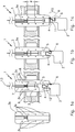
- the Fig. 1a shows a trigger unit 1 for an avalanche rescue system.
- a trigger unit 1 for an avalanche rescue system Of the Fig. 1a are two mutually complementary shaped elements 3a, 3b can be seen. These can be interconnected by means of connections 3c arranged on them, in this exemplary embodiment plug-in connections, in this exemplary embodiment being plugged together. In the connected state they form a coupling unit 3, in particular a handle holder, the trip unit. 1
- the trip unit 1 could also be formed in one piece or in one piece.
- a schematically illustrated actuating handle 2 of the trip unit 1 can be seen.
- a coupling piece 4 is arranged, which engages positively in a coupling element 5.
- the coupling piece 4 and the coupling element 5 are arranged in a coupling channel 6 formed by opposing recesses of the two elements 3a, 3b.
- the coupling channel 6 is rectangular in cross-section, so that the coupling element 5 and the coupling piece 4 are rotatably mounted in the coupling channel 6.
- the coupling unit 3 is fixed by means of a fixing section 8 to a carrier system 9, in particular to a shoulder belt of a backpack serving as a carrier system 9, by means of a lashing.
- the coupling element 5 is connected to a cable nipple 17 of a cable 13.
- the cable 13 passes through a portion of the coupling element 5 and is secured by the cable nipple 17 by the cable nipple 17 is supported on the coupling element 5.
- the coupling piece 4 and the coupling element 5 are arranged displaceably in the coupling channel 6.
- the cable nipple 17 and the cable 13 are taken from the coupling element 5 when it is moved in the coupling channel 6.
- the cable 13 can with a functional unit of Avalanche rescue system. By shifting the coupled with the cable 13 coupling element 55 - in the in Fig. 1a shown representation - down the functional unit can be triggered or activated.
- the coupling unit 3 or the elements 3a, 3b have an auxiliary mounting hole 7 opening into the coupling channel 6.
- a mounting auxiliary pin can be introduced, through which the coupling element 5, for example, for producing a coupling connection between the coupling piece 4 and the coupling element 5, can be pushed out of the coupling channel 6.
- the coupling element 5 additionally has a latching section 12 in this exemplary embodiment.
- the latching portion 12 is formed such that the coupling piece 4 can be pushed onto the coupling element 5 and then enters into coupling connection with this.
- auxiliary mounting channel 7 or a latching portion 12 is formed in a trip unit.
- Fig. 1b and the Fig. 1c now show the same trip unit 1, wherein for reasons of simplification, the element 3b is not shown in each case.
- FIG. 1b and 1c two snapshots of the trip unit 1, while using the operating handle 2, the coupling piece 4 and the coupling piece 5 are pulled out of the coupling unit 3.
- Fig. 1c a position shown in which the coupling piece 4 has already left the coupling channel 6.
- the coupling piece 4 can be solved simply, safely and with the least expenditure of force by the coupling element 5, in particular automatically with further pulling of the operating handle 2.
- the coupling piece 4 and the coupling element 5 in a coupling connection region 10 each have a bevel 11.
- the chamfer 11 is oriented such that upon removal of the coupling piece 4 and the coupling element 5 from the coupling channel 6, the coupling piece 4 laterally slides away from the coupling element 5 and the coupling connection is thus automatically released.
- the coupling element 5 is displaced by a predefinable triggering distance d.
- the length of the coupling channel 6 has been selected such that the coupling element 5 can be displaced at least by the triggering distance d within the coupling channel 6, without the coupling connection between the coupling piece 4 and the coupling element 5 can be solved.
- the coupling element 5 is displaced at least by the triggering distance d before the coupling piece 4 and the operating handle 2 is decoupled or in the Fig. 1c corresponding position arrives. This ensures that the cable 13 can be displaced at least by the release distance d.
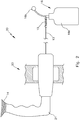
- the triggering unit 20 corresponds in this embodiment of the trip unit 1. It differs only in the design of an alternative trained operating handle 21.
- the actuating handle 21 has in particular a mouthpiece 14 on.
- the mouthpiece 14 can be brought to the mouth of a user or a person to be protected by the avalanche rescue system and the person, for example, be supplied with air.
- the operating handle 21 is connected via a hose, not shown, with a ventilation function unit.
- the cable 13, a return element 15 is attached, which sets the cable 13 under tension.
- the restoring element 15 is designed as a spring element. By selecting the spring hardness and the spring travel of the restoring element 15, the triggering distance d ( Fig. 1c ) as well as a minimum tripping force required for tripping.
- a functional unit 16 is connected to the cable 13.
- the functional unit 16 is formed in this embodiment as an avalanche balloon 16b, which is connected to a compressed gas cartridge 16a.
- the functional unit 16 is set up so that when the cable pull 13 is displaced by the release distance d, the compressed gas cartridge 16a is opened and inflates the avalanche balloon 16b. In other words, the functional unit 16 is triggered when the cable 13 is moved by the release distance d.
- the invention makes it possible to pull the actuating handle 2 or the actuating handle 21 away from the triggering unit 1 or triggering unit 20 and thus reliably trigger the functional unit 16.
- the Fig. 3 shows an alternative embodiment of a coupling unit 50.
- a coupling piece 4 and a coupling element 5 are at least partially disposed in a coupling channel 6.
- the coupling element 5 is complete and the coupling piece 4 is partially arranged in the coupling channel 6.
- Both the coupling element 5 and the coupling piece 4 are each connected to a cable, not shown here.
- the respective cables are fixed by threaded pins 51, 52 in the coupling element 5 or coupling piece 4.
- the peculiarity of the embodiment according to the Fig. 3 is in that the coupling channel 6 is formed in an end piece 53 which is screwed into a coupling unit body 54.
- the coupling unit 50 can be brought back to its position of use by the end piece 53 is unscrewed. This allows the coupling piece 4 and the coupling element 5 to be brought back into engagement with each other. Subsequently, the end piece 53 can be screwed back into the coupling unit body 54. In order to prevent the tail 53 from being screwed in too far, the length of the thread 55 is limited.
- a stop 56 formed as a disk is provided.
- adjusting means 57 which may be formed as a threaded pin, manufacturing tolerances of a cable and connected thereto units can be compensated. After adjustment, the adjustment can be fixed, for. B. with a screw lock or an adhesive.
Abstract
Die Erfindung betrifft eine Auslöseeinheit (1, 20) für ein Lawinenrettungssystem, mit einem mit einem Kopplungsstück (4) verbundenen Betätigungsgriff (2, 21). Erfindungsgemäß zeichnet sie sich aus durch ein mit einer Funktionseinheit (16) des Lawinenrettungssystems verbindbares Kopplungselement (5), wobei das Kopplungsstück (4) und das Kopplungselement (5) in einem Kopplungskanal (6) einer Kopplungseinheit (3) der Auslöseeinheit (1, 20) verschiebbar sind und durch den Kopplungskanal (6) in Kopplungsverbindung gehalten werden und die Kopplungsverbindung lösbar ist, wenn das Kopplungsstück (4) und/oder das Kopplungselement (5) den Kopplungskanal (6) verlassen.The invention relates to a triggering unit (1, 20) for an avalanche rescue system, having an actuating handle (2, 21) connected to a coupling piece (4). According to the invention, it is distinguished by a coupling element (5) which can be connected to a functional unit (16) of the avalanche rescue system, the coupling piece (4) and the coupling element (5) being arranged in a coupling channel (6) of a coupling unit (3) of the triggering unit (1, 20 ) are displaceable and are held in coupling connection by the coupling channel (6) and the coupling connection is releasable when the coupling piece (4) and / or the coupling element (5) leave the coupling channel (6).
Description
Die Erfindung geht aus von einer Auslöseeinheit für ein Lawinenrettungssystem mit einem mit einem Kopplungsstück verbundenen Betätigungsgriff.The invention relates to an activation unit for an avalanche rescue system with an operating handle connected to a coupling piece.
Eine solche Auslöseeinheit ist beispielsweise aus der
Lawinenrettungssysteme, beispielsweise für Skifahrer oder Bergsteiger, weisen vorteilhafterweise unterschiedliche Funktionseinheiten auf, beispielsweise einen Lawinenairbag und/oder einen Lawinenballon und/oder eine Beatmungsfunktionseinheit. Jedoch muss sichergestellt werden, dass im Gefahrenfall, d. h. wenn eine Lawine sich nähert, eine zu schützende Person möglichst sicher und schnell die unterschiedlichen Funktionseinheiten respektive Teilrettungssysteme des Lawinenrettungssystems auslösen kann. Daher ist aus dem eingangs beschriebenen Stand der Technik eine Auslöseeinheit mit einem Betätigungsgriff bekannt, mit dem durch Wegreißen eines Teils eines Betätigungsgriffs von einem anderen Teil mehrere Funktionseinheiten des Lawinenrettungssystems gleichzeitig aktiviert bzw. ausgelöst werden können. Dabei ist der abreißbare Teil des Betätigungsgriffs selbst Teil einer Funktionseinheit. Insbesondere weist dieser Teil des Betätigungsgriffs ein Mundstück auf. Somit können Funktionseinheiten ausgelöst werden und gleichzeitig das Mundstück frei beweglich zum Mund der Person geführt werden.Avalanche rescue systems, for example for skiers or climbers, advantageously have different functional units, for example an avalanche airbag and / or an avalanche balloon and / or a ventilation functional unit. However, it must be ensured that in case of danger, d. H. When an avalanche approaches, a person to be protected can safely and quickly trigger the various functional units or partial rescue systems of the avalanche rescue system. Therefore, from the prior art described above, a trip unit with an operating handle is known, can be activated or triggered by tearing away a part of an operating handle of another part of several functional units of the avalanche rescue system simultaneously. The tearable part of the operating handle itself is part of a functional unit. In particular, this part of the operating handle has a mouthpiece. Thus, functional units can be triggered and at the same time the mouthpiece be moved freely to the mouth of the person.
Problematisch im Stand der Technik ist jedoch, dass die Funktionsfähigkeit einer solchen Auslöseeinheit möglichst zu jedem Zeitpunkt und in jeder Situation gewährleistet werden muss. Insbesondere sollte sichergestellt werden, dass der Griff nicht abgelöst wird, bevor die Funktionseinheit ausgelöst wird.However, a problem in the prior art is that the functionality of such a trip unit must be ensured as possible at any time and in any situation. In particular, it should be ensured that the handle is not detached before the functional unit is triggered.
Primäre Aufgabe der Erfindung ist, dass eine Ablösung des Griffs nicht vor der Auslösung der Funktionseinheit, beispielsweise eines Airbags, erfolgt.The primary object of the invention is that a detachment of the handle does not take place before the activation of the functional unit, for example an airbag.
Sekundäre Aufgabe der vorliegenden Erfindung ist es daher, eine Auslöseeinheit für ein Lawinenrettungssystem zu verbessern und insbesondere eine kostengünstige und einfach herstellbare Lösung anzubieten, die eine Auslösung von Funktionseinheiten eines Lawinenrettungssystems selbst unter widrigsten Bedingungen gewährleisten kann.It is therefore a secondary object of the present invention to improve an activation unit for an avalanche rescue system, and in particular a cost-effective and easily manufactured solution which can guarantee the triggering of functional units of an avalanche rescue system even under the most adverse conditions.
Gelöst wird die Aufgabe durch eine Auslöseeinheit für ein Lawinenrettungssystem mit den Merkmalen des Anspruchs 1. Insbesondere kann die Aufgabe gelöst werden durch eine Auslöseeinheit mit einem ein Kopplungsstück aufweisenden Betätigungsgriff und mit einem mit einer Funktionseinheit des Lawinenrettungssystems verbindbaren Kopplungselement, wobei das Kopplungsstück und das Kopplungselement in einem Kopplungskanal eines Griffhalters der Auslöseeinheit verschiebbar sind und durch den Kopplungskanal in Kopplungsverbindung gehalten werden und die Kopplungsverbindung lösbar ist, wenn das Kopplungsstück und/oder das Kopplungselement den Kopplungskanal verlassen.The object is achieved by a triggering unit for an avalanche rescue system with the features of claim 1. In particular, the object can be achieved by a trip unit having a coupling piece having an actuating handle and a connectable to a functional unit of the avalanche rescue coupling element, wherein the coupling piece and the coupling element in a coupling channel of a handle holder of the trip unit are displaceable and are held by the coupling channel in coupling connection and the coupling connection is detachable when the coupling piece and / or the coupling element leave the coupling channel.
Dabei kann das Kopplungselement mit einer Funktionseinheit des Lawinenrettungssystems verbunden sein. Insbesondere kann vorgesehen sein, dass durch Verschieben des Kopplungselements die Funktionseinheit ausgelöst wird. Die Kopplungseinheit kann als Griffhalter dienen. Der Betätigungsgriff kann das Kopplungsstück aufweisen. Dabei kann das Kopplungsstück einstückig mit dem Betätigungsgriff ausgebildet sein oder über ein Verbindungselement, z. B. einen Seilzug, mit diesem verbunden sein.In this case, the coupling element can be connected to a functional unit of the avalanche rescue system. In particular, it can be provided that the functional unit is triggered by displacement of the coupling element. The coupling unit can serve as a handle holder. The operating handle may comprise the coupling piece. In this case, the coupling piece may be formed integrally with the actuating handle or via a connecting element, for. As a cable to be connected to this.
Wird der Betätigungsgriff vom Griffhalter wegbewegt respektive weggerissen, so nimmt das Kopplungsstück das Kopplungselement entlang des Kopplungskanals mit. Dadurch kann die Funktionseinheit ausgelöst werden. Verlassen anschließend das Kopplungsstück und/oder das Kopplungselement den Kopplungskanal, so kann die Kopplungsverbindung gelöst werden. Mit anderen Worten bildet der Kopplungskanal eine Hülse, die die Auflösung der Kopplungsverbindung zwischen Kopplungselement und Kopplungsstück verhindert, solange sich das Kopplungsstück und/oder Kopplungselement im Kopplungskanal befinden. Somit kann sichergestellt werden, dass das Kopplungselement entlang des Kopplungskanals bewegt wird und dadurch die Funktionseinheit auslöst und erst anschließend der Betätigungsgriff frei bewegt werden kann.If the actuating handle is moved away from the handle holder or torn away, the coupling piece takes along the coupling element along the coupling channel. As a result, the functional unit can be triggered. After leaving the coupling piece and / or the coupling element the coupling channel, then the Coupling connection can be solved. In other words, the coupling channel forms a sleeve, which prevents the dissolution of the coupling connection between the coupling element and the coupling piece, as long as the coupling piece and / or coupling element are located in the coupling channel. Thus, it can be ensured that the coupling element is moved along the coupling channel and thereby triggers the functional unit and only then the operating handle can be moved freely.
Besonders vorteilhaft ist es, wenn die Kopplungsverbindung form- und/oder kraftschlüssig ist. Dadurch können Kopplungsverbindungen auf besonders einfache Weise hergestellt werden. Insbesondere können Kopplungsstück und Kopplungselement ineinander eingreifen. Auch ermöglichen form- und/oder kraftschlüssige Kopplungsverbindungen, dass die Auslöseeinheit mehrfach wiederverwendbar ausgestaltet werden kann, da nach einem Lösen der Kopplungsverbindung diese auf einfache Weise wiederhergestellt werden kann. So kann das Lawinenrettungssystem auch nach einem Einsatz erneut verwendet werden, ohne dass es teurer Austauschteile bedarf.It is particularly advantageous if the coupling connection is positive and / or non-positive. As a result, coupling connections can be made in a particularly simple manner. In particular, the coupling piece and the coupling element can engage in one another. Also allow positive and / or non-positive coupling connections, that the trip unit can be designed to be reusable many times, as after a release of the coupling connection, this can be easily restored. Thus, the avalanche rescue system can be reused even after use, without the need for expensive replacement parts.
Ein Kraftschluss kann beispielsweise durch eine elektrische und/oder magnetische Verbindung erreicht werden. Zur Herstellung eines Formschlusses können das Kopplungsstück und das Kopplungselement zumindest bereichsweise komplementär geformt sein.A frictional connection can be achieved for example by an electrical and / or magnetic connection. To produce a positive connection, the coupling piece and the coupling element can be shaped at least partially complementary.
Es kann vorgesehen sein, dass das Kopplungselement und/oder das Kopplungsstück drehfest im Kopplungskanal anordenbar sind. Beispielsweise kann der Kopplungskanal einen nicht kreisförmigen Querschnitt aufweisen. Insbesondere können das Kopplungselement und/oder das Kopplungsstück zumindest abschnittsweise im Querschnitt rotationsasymmetrisch oval gebildet sein. Auch können das Kopplungselement und/oder das Kopplungsstück im Querschnitt trapezförmig, vorzugsweise rechteckig, gebildet sein. Vorteilhafterweise ist jeweils der Querschnitt des Kopplungskanals zumindest abschnittsweise komplementär zum Kopplungselement und/oder zum Kopplungsstück gebildet. Weisen nun das Kopplungselement und/oder das Kopplungsstück einen dem Kopplungskanal entsprechenden bzw. komplementären Querschnitt auf, so können das Kopplungselement und/oder das Kopplungsstück drehfest im Kopplungskanal angeordnet werden. So kann beispielsweise sichergestellt werden, dass der Betätigungsgriff stets in einer optimalen Position bzw. Lage am Griffhalter angeordnet ist. Insbesondere kann vorgesehen sein, dass der Betätigungsgriff in einer Lage am Griffhalter angeordnet wird, die es einer Person ermöglicht, den Betätigungsgriff sicher zu greifen.It can be provided that the coupling element and / or the coupling piece can be arranged rotationally fixed in the coupling channel. For example, the coupling channel may have a non-circular cross-section. In particular, the coupling element and / or the coupling piece at least partially in cross-section be formed rotationally asymmetric oval. Also, the coupling element and / or the coupling piece in cross-section trapezoidal, preferably rectangular, be formed. Advantageously, the cross-section of the coupling channel is at least partially complementary to the coupling element and / or the coupling piece. If now the coupling element and / or the coupling piece have a cross-section corresponding or complementary to the coupling channel, then the coupling element and / or the coupling piece can be arranged in a rotationally fixed manner in the coupling channel. For example, it can be ensured that the actuating handle is always arranged in an optimal position or position on the handle holder. In particular, it can be provided that the actuating handle is arranged in a position on the handle holder, which allows a person to grip the operating handle safely.
Alternativ kann das Kopplungselement nicht drehfest im Kopplungskanal angeordnet sein. Insbesondere können beide einen kreisrunden Querschnitt aufweisen.Alternatively, the coupling element can not be arranged rotationally fixed in the coupling channel. In particular, both may have a circular cross-section.
Es kann vorgesehen werden, dass die Kopplungseinheit, insbesondere der Griffhalter, aus zumindest zwei Elementen zusammengesetzt ist, wobei der Kopplungskanal durch zumindest zwei der Elemente ausgebildet ist. Somit kann die Kopplungseinheit auf besonders einfache Weise hergestellt und der Kopplungskanal ausgebildet werden. Beispielsweise kann die Kopplungseinheit aus zwei Halbzylindern gebildet werden, die, wenn sie zusammengefügt sind, in ihrem Innenbereich den Kopplungskanal bilden.It can be provided that the coupling unit, in particular the handle holder, is composed of at least two elements, wherein the coupling channel is formed by at least two of the elements. Thus, the coupling unit can be manufactured in a particularly simple manner and the coupling channel can be formed. For example, the coupling unit can be formed from two half-cylinders, which, when joined, form the coupling channel in their inner region.
Die Kopplungseinheit kann an einem Ende ein abnehmbares Endstück aufweisen. Wenn das Endstück abgenommen ist, können Kopplungselement und Kopplungsstück einfach gekoppelt werden. Anschließend kann das Endstück wieder aufgesetzt, z. B. aufgeschraubt, eingeschraubt oder aufgeclipst werden, um Kopplungsstück und Kopplungselement in Eingriff zu halten.The coupling unit may have a removable end piece at one end. When the tail is removed, the coupling element and coupling piece can be easily coupled. Then the tail can be replaced, z. B. screwed, screwed or clipped to hold coupling piece and coupling element in engagement.
Bei einer besonders bevorzugten Ausgestaltung der Erfindung kann des Weiteren vorgesehen sein, dass das Kopplungselement und/oder das Kopplungsstück im Kopplungskanal mindestens um eine vorgebbare Auslösedistanz d verschiebbar sind. Es kann beispielsweise vorgesehen sein, dass die Funktionseinheit so mit dem Kopplungselement bzw. mit dem Kopplungsstück verbunden ist, dass wenn das Kopplungselement bzw. das Kopplungsstück um eine vorgebbare Auslösedistanz d verschoben wird, die Funktionseinheit ausgelöst wird. Weist daher der Kopplungskanal eine Länge auf, die es ermöglicht, dass das Kopplungselement bzw. das Kopplungsstück innerhalb des Kopplungskanals mindestens um die vorgebbare Auslösedistanz d verschoben werden können, so kann somit auf einfache Weise sichergestellt werden, dass die Funktionseinheit zuverlässig ausgelöst wird, bevor das Kopplungselement vom Kopplungsstück gelöst werden kann.In a particularly preferred embodiment of the invention may further be provided that the coupling element and / or the coupling piece in the coupling channel at least by a predetermined release distance d are displaced. It can be provided, for example, that the functional unit is connected to the coupling element or to the coupling piece such that when the coupling element or the coupling piece is displaced by a predefinable triggering distance d, the functional unit is triggered. If, therefore, the coupling channel has a length which allows the coupling element or the coupling piece to be displaced within the coupling channel at least by the predefinable triggering distance d, it can thus be ensured in a simple manner that the functional unit is reliably triggered before the coupling Coupling element can be solved by the coupling piece.
Des Weiteren kann vorgesehen sein, dass die Kopplungseinheit eine in den Kopplungskanal mündende Montagehilfsbohrung oder -öffnung aufweist. Nach einem Einsatz der Auslöseeinheit kann das Kopplungsstück vom Kopplungselement gelöst sein. Für einen erneuten Einsatz müssen beide zunächst wieder verbunden werden. Dazu kann ein Montagehilfsstift durch die Montagehilfsbohrung bzw. -öffnung in den Kopplungskanal eingeführt werden. Mit dem Montagehilfsstift kann dann beispielsweise das Kopplungselement soweit aus dem Kopplungskanal geschoben werden, bis es sich wieder mit dem Kopplungsstück verbinden lässt.Furthermore, it can be provided that the coupling unit has a mounting auxiliary bore or opening opening into the coupling channel. After use of the trip unit, the coupling piece can be detached from the coupling element. For a second use, both must first be reconnected. For this purpose, an auxiliary assembly pin can be inserted through the auxiliary mounting hole or opening in the coupling channel. With the auxiliary assembly pin, for example, the coupling element can then be pushed out of the coupling channel until it can be reconnected to the coupling piece.
Vorteilhaft ist auch, wenn die Kopplungseinheit einen Fixierabschnitt zur Befestigung der Kopplungseinheit an einem Trägersystem des Lawinenrettungssystems aufweist. Das Trägersystem kann beispielsweise ein Rucksack oder ein in einen Rucksack eingefügtes Trägerelement sein, auf oder an dem unterschiedliche Elemente, insbesondere Funktionseinheiten, des Lawinenrettungssystems angeordnet sind. Das Trägersystem bzw. der Rucksack kann beispielsweise einen Schultergurt mit einer Laschung aufweisen. In die Laschung kann der Fixierabschnitt der Kopplungseinheit eingeschoben werden und so die Kopplungseinheit bzw. die Auslöseeinheit, insbesondere an einer vorgegebenen Position und/oder in einer vorgegebenen Lage, fixiert werden. Dadurch kann die Auslöseeinheit am Trägersystem an- bzw. abmontiert werden. Die Position und/oder Lage können zudem so gewählt sein, dass die Person den Betätigungsgriff im Notfall mühelos erreichen kann.It is also advantageous if the coupling unit has a fixing section for fastening the coupling unit to a carrier system of the avalanche rescue system. The carrier system can be for example a backpack or a carrier element inserted into a backpack, on or on which different elements, in particular functional units, of the avalanche rescue system are arranged. The carrier system or the backpack, for example, have a shoulder strap with a lashing. In the Laschung the fixing portion of the coupling unit can be inserted and so the coupling unit or the release unit, in particular at a predetermined position and / or in a predetermined position, are fixed. This allows the trip unit on the carrier system on or removed. The position and / or position may also be chosen so that the person can easily reach the operating handle in an emergency.
Die Lösbarkeit des Kopplungselements vom Kopplungsstück kann erleichtert werden, wenn das Kopplungselement und/oder das Kopplungsstück in einem Kopplungsverbindungsbereich eine Anschrägung aufweisen.The releasability of the coupling element from the coupling piece can be facilitated if the coupling element and / or the coupling piece have a bevel in a coupling connection region.
Besonders vorteilhaft ist weiterhin, wenn das Kopplungselement und/oder das Kopplungsstück einen Rastabschnitt zur Herstellung der Kopplungsverbindung aufweisen. In diesem Fall kann, insbesondere nach einem Einsatz der Auslöseeinheit, die Verbindung zwischen dem Kopplungselement und dem Kopplungsstück wieder dadurch hergestellt werden, dass das Kopplungsstück in den Kopplungskanal eingeführt wird, bis es am Kopplungselement einrastet. Dazu kann der Rastabschnitt aus elastischem Material gebildet sein.It is furthermore particularly advantageous if the coupling element and / or the coupling piece have a latching section for producing the coupling connection. In this case, in particular after use of the trip unit, the connection between the coupling element and the coupling piece can be made again by inserting the coupling piece into the coupling channel until it engages with the coupling element. For this purpose, the latching portion may be formed of elastic material.
Besonders vorteilhaft ist es, wenn das Kopplungselement und/oder das Kopplungsstück mit einem Seilzug verbunden sind. Beispielsweise kann dann das Kopplungselement über einen Seilzug mit der Funktionseinheit verbunden sein. Dadurch kann die Funktionseinheit beabstandet von der Auslöseeinheit angeordnet werden und dennoch mit Hilfe der Auslöseeinheit ausgelöst werden. Dabei ist besonders vorteilhaft, dass ein Seilzug platzsparend angeordnet werden kann, ein geringes Gewicht und eine nahezu beliebig wählbare Länge aufweisen kann.It when the coupling element and / or the coupling piece are connected to a cable is particularly advantageous. For example, then the coupling element can be connected via a cable to the functional unit. As a result, the functional unit can be arranged at a distance from the tripping unit and nevertheless be triggered with the aid of the tripping unit. It is particularly advantageous that a cable can be arranged to save space, a low weight and an almost arbitrary length can have.
Zudem kann vorgesehen sein, dass das Kopplungselement und/oder das Kopplungsstück als Seilzugnippel ausgebildet sind. Insbesondere kann vorgesehen sein, dass sowohl das Kopplungselement als auch das Kopplungsstück als Seilzugnippel ausgebildet sind. Jeder Seilzugnippel kann mit jeweils einem Seilzug verbunden sein. Bei geeigneter Dimensionierung der Abmessung des Kopplungskanals in Relation zum Kopplungselement und/oder zum Kopplungsstück kann dann auf besonders einfache Weise eine Kopplungsverbindung hergestellt werden. Dazu muss lediglich der dem Kopplungselement entsprechende Seilzugnippel aus dem Kopplungskanal herausgeschoben werden, der dem Kopplungsstück entsprechende Seilzugnippel hinter den dem Kopplungselement entsprechenden Seilzugnippel angeordnet werden und die Anordnung des Kopplungselements und des Kopplungsstücks wieder in den Kopplungskanal eingebracht werden. Gelöst werden kann eine derart gebildete Kopplungsverbindung dadurch, dass am Seilzug des dem Kopplungsstück entsprechenden Seilzugnippels gezogen wird, bis die Anordnung erneut den Kopplungskanal verlässt, da die Seilzugnippel in einer solchen Anordnung an und für sich nicht miteinander starr bzw. fest verbunden sind.In addition, it can be provided that the coupling element and / or the coupling piece are designed as Seilzugnippel. In particular, it can be provided that both the coupling element and the coupling piece are designed as Seilzugnippel. Each cable nipple can be connected to one cable each. With a suitable dimensioning of the dimension of the coupling channel in relation to the coupling element and / or to the coupling piece, a coupling connection can then be produced in a particularly simple manner. For this purpose, only the coupling element corresponding Seilzugnippel must be pushed out of the coupling channel, the coupling piece corresponding Seilzugnippel be arranged behind the coupling element corresponding Seilzugnippel and the arrangement of the coupling element and the coupling piece are again introduced into the coupling channel. Can be solved so formed coupling connection characterized in that the cable pull of the coupling piece corresponding cable nipple is pulled until the assembly again leaves the coupling channel, since the cable nipple in such an arrangement in and of themselves are not rigidly connected or fixed.
Besonders vorteilhaft ist es, wenn die Seilzugnippel Aussparungen aufweisen, sodass der mit einem Seilzugnippel verbundene Seilzug den anderen Seilzugnippel durchgreifen kann.It is particularly advantageous if the cable nipples have recesses so that the cable pull connected to a cable nipple can pass through the other cable nipple.
Der Betätigungsgriff kann mit zusätzlichen Funktionen bzw. Funktionselementen ausgestattet werden. Insbesondere kann vorgesehen sein, dass der Betätigungsgriff ein Mundstück aufweist. Mittels des Mundstücks kann dann eine Beatmung einer, beispielsweise verschütteten, Person ermöglicht werden, wobei der Betätigungsgriff hierzu mit einer Beatmungsfunktionseinheit beispielsweise über einen Schlauch verbunden sein kann. Nach dem Lösen des Betätigungsgriffs von der Auslösevorrichtung kann der Betätigungsgriff dem Mund der Person zugeführt werden.The operating handle can be equipped with additional functions or functional elements. In particular, it can be provided that the actuating handle has a mouthpiece. By means of the mouthpiece, ventilation of a person buried, for example, can then be made possible, the actuating handle for this purpose being able to be connected to a ventilation functional unit, for example via a hose. After releasing the operating handle of the triggering device, the operating handle can be supplied to the mouth of the person.
In den Rahmen der Erfindung fällt des Weiteren eine Verwendung eines Betätigungsgriffs mit einem Kopplungsstück in einer erfindungsgemäßen Auslöseeinheit, wobei das Kopplungsstück und ein Kopplungselement der Auslöseeinheit in einem Kopplungskanal einer Kopplungseinheit der Auslöseeinheit verschiebbar sind und durch den Kopplungskanal in Kopplungsverbindung gehalten werden und die Kopplungsverbindung lösbar ist, wenn das Kopplungsstück und/oder das Kopplungselement den Kopplungskanal verlassen.In the context of the invention, furthermore, a use of an actuating handle with a coupling piece in a trip unit according to the invention, wherein the coupling piece and a coupling element of the trip unit in a coupling channel of a coupling unit of the trip unit are displaceable and are held in coupling connection by the coupling channel and the coupling connection is detachable when the coupling piece and / or the coupling element leave the coupling channel.
Insbesondere kann vorgesehen sein, unterschiedliche erfindungsgemäße Betätigungsgriffe zu verwenden bzw. vorzusehen. So können beispielsweise unterschiedliche Betätigungsgriffe individuell an Bedürfnisse der den Betätigungsgriff nutzenden Person angepasst sein. Beispielsweise können die Betätigungsgriffe unterschiedlich geformte Mundstücke aufweisen. Weisen die Betätigungsgriffe geeignete Kopplungsstücke auf, so können unterschiedliche Betätigungsgriffe mit ein und dergleichen Auslöseeinheit verwendet werden.In particular, it may be provided to use or provide different actuating handles according to the invention. For example, different operating handles can be adapted individually to the needs of the person using the operating handle. For example, the operating handles may have differently shaped mouthpieces. Do the operating handles have suitable coupling pieces, so different operating handles can be used with one and the same trip unit.
Des Weiteren fällt in den Rahmen der Erfindung eine Auslösevorrichtung mit einer erfindungsgemäßen Auslöseeinheit, wobei die Auslösevorrichtung ein Rückstellelement zur Rückstellung des Kopplungselements der Auslöseeinheit aufweist. Das Rückstellelement kann beispielsweise ein Federelement, insbesondere ein Torsionsfederelement, aufweisen und/oder als solches ausgebildet sein. Das Rückstellelement kann, vorzugsweise über einen Seilzug, mit dem Kopplungselement verbunden sein. Somit ist es möglich, dass nach einer Auslösung das Kopplungselement wieder in den Kopplungskanal automatisch zurückgezogen wird. Auch kann mittels des Rückstellelements eine für eine Auslösung zu überwindende Zugkraftschwelle eingestellt werden. Dazu kann insbesondere die Federhärte eines als Federelement ausgebildeten Rückstellelements eingestellt und/oder gewählt werden. Somit können versehentliche Fehlauslösungen wirkungsvoll verhindert werden. Ferner kann vorgesehen werden, dass die vorgebbare Auslösedistanz d dem Federweg eines als Federelement ausgebildeten Rückstellelements entspricht oder in Abhängigkeit von diesem gewählt wird.Furthermore, falls within the scope of the invention, a triggering device with a trip unit according to the invention, wherein the triggering device has a return element for returning the coupling element of the trip unit. The restoring element can, for example, have a spring element, in particular a torsion spring element, and / or be designed as such. The restoring element can be connected to the coupling element, preferably via a cable pull. Thus, it is possible that after triggering the coupling element is automatically withdrawn into the coupling channel. Also can be adjusted by means of the return element to be overcome for a release tension threshold. For this purpose, in particular the spring stiffness of a resetting element designed as a spring element can be adjusted and / or selected. Thus, accidental false triggering can be effectively prevented. Furthermore, it can be provided that the presettable triggering distance d corresponds to the spring travel of a restoring element designed as a spring element or is selected as a function of this.
Das Rückstellelement kann in alternativer Ausgestaltung auch mit dem Kopplungsstück, vorzugsweise über einen Seilzug, verbunden sein, insbesondere um eine Rückstellung des Kopplungsstücks nach einer Auslösung zu bewirken.The restoring element can also be connected to the coupling piece, preferably via a cable pull, in an alternative embodiment, in particular in order to bring about a return of the coupling piece after a release.
Vorteilhafterweise können die Kopplungseinheit und/oder das Kopplungselement und/oder der Betätigungsgriff als Spritzgussteil oder im 3D-Druck als 3D-Druck-Teil zumindest bereichsweise gebildet sein.Advantageously, the coupling unit and / or the coupling element and / or the actuating handle may be formed as an injection molded part or in 3D printing as a 3D printing part at least partially.
Ebenso kann vorgesehen sein, die Kopplungseinheit und/oder das Kopplungselement und/oder den Betätigungsgriff aus einem korrosionsbeständigen Material, beispielsweise aus Aluminium und/oder Kunststoff, vorzugsweise ABS-Kunststoff, auszubilden.It can also be provided to form the coupling unit and / or the coupling element and / or the operating handle made of a corrosion-resistant material, for example of aluminum and / or plastic, preferably ABS plastic.
Weiterhin kann in besonders vorteilhafter Weise vorgesehen sein, dass die Auslöseeinheit mit mehr als einer Funktionseinheit über das Kopplungselement verbindbar ist. Beispielsweise kann das Kopplungselement mit zwei oder drei Funktionseinheiten verbindbar sein. Die Funktionseinheiten können beispielsweise als Lawinenairbag, als Lawinenballon und/oder als Lawinenpiepser und/oder als Beatmungsfunktionseinheit ausgebildet sein.Furthermore, it can be provided in a particularly advantageous manner that the trip unit with more than one functional unit is connectable via the coupling element. For example, the coupling element with two or three functional units can be connected. The functional units can be designed, for example, as an avalanche airbag, as an avalanche balloon and / or as an avalanche beeper and / or as a ventilation functional unit.
Weitere Merkmale und Vorteile der Erfindung ergeben sich aus der nachfolgenden detaillierten Beschreibung von Ausführungsbeispielen der Erfindung, anhand der Figuren der Zeichnung, die erfindungswesentliche Einzelheiten zeigen, sowie aus den Ansprüchen. Die dort gezeigten Merkmale sind nicht notwendig maßstäblich zu verstehen und derart dargestellt, dass die erfindungsgemäßen Besonderheiten deutlich sichtbar gemacht werden können. Die verschiedenen Merkmale können je einzeln für sich oder zu mehreren in beliebigen Kombinationen bei Varianten der Erfindung verwirklicht sein.Further features and advantages of the invention will become apparent from the following detailed description of embodiments of the invention, with reference to the figures of the drawing, which show details essential to the invention, and from the claims. The features shown there are not necessarily to scale and presented in such a way that the features of the invention can be made clearly visible. The various features may be implemented individually for themselves or for a plurality of combinations in variants of the invention.
In der schematischen Zeichnung sind Ausführungsbeispiele der Erfindung sowie Ansichten einzelner Komponenten der erfindungsgemäßen Auslöseeinheit sowie der erfindungsgemäßen Auslösevorrichtung dargestellt und werden in der nachstehenden Beschreibung näher erläutert.In the schematic drawing embodiments of the invention and views of individual components of the trip unit according to the invention and the tripping device according to the invention are shown and are explained in more detail in the following description.
Es zeigen:
- Fig. 1a - Fig. 1c
- ein Ausführungsbeispiel einer erfindungsgemäßen Auslöseeinheit mit unterschiedlichen Stellungen des Kopplungselements bzw. Kopplungsstücks;
- Fig. 2
- eine Auslösevorrichtung mit einer alternativen Ausführung der Auslöseeinheit;
- Fig. 3
- eine alternative Ausführungsform einer Kopplungseinheit.
- Fig. 1a - Fig. 1c
- an embodiment of a trip unit according to the invention with different positions of the coupling element or coupling piece;
- Fig. 2
- a triggering device with an alternative embodiment of the trip unit;
- Fig. 3
- an alternative embodiment of a coupling unit.
Die
In einer alternativen Ausführungsform könnte die Auslöseeinheit 1 auch einteilig bzw. einstückig ausgebildet sein.In an alternative embodiment, the trip unit 1 could also be formed in one piece or in one piece.
Im Folgenden werden der innere Aufbau der Kopplungseinheit 3 sowie in der Kopplungseinheit 3 enthaltene Komponenten der Auslöseeinheit 1 näher erläutert. Dazu ist in der
Zu erkennen ist zunächst ein schematisch dargestellter Betätigungsgriff 2 der Auslöseeinheit 1. Am Betätigungsgriff 2 ist ein Kopplungsstück 4 angeordnet, das formschlüssig in ein Kopplungselement 5 eingreift. Das Kopplungsstück 4 und das Kopplungselement 5 sind in einem durch gegenüberliegende Aussparungen der beiden Elemente 3a, 3b gebildeten Kopplungskanal 6 angeordnet. Der Kopplungskanal 6 ist im Querschnitt rechteckig ausgebildet, sodass das Kopplungselement 5 und das Kopplungsstück 4 im Kopplungskanal 6 drehfest angeordnet sind.First, a schematically illustrated actuating handle 2 of the trip unit 1 can be seen. On the
Die Kopplungseinheit 3 ist mittels eines Fixierabschnitts 8 an einem Trägersystem 9, insbesondere an einem Schultergurt eines als Trägersystem 9 dienenden Rucksacks, mittels einer Laschung fixiert.The
Der
Der Seilzug 13 kann mit einer Funktionseinheit des
Lawinenrettungssystems verbunden sein. Durch Verlagerung des mit dem Seilzug 13 gekoppelten Kopplungselements 55 - in der in der
Avalanche rescue system. By shifting the coupled with the
Der
In alternativen Ausführungsformen der Erfindung ist es vorgesehen, dass entweder ein Montagehilfskanal 7 oder ein Rastabschnitt 12 in einer Auslöseeinheit ausgebildet ist.In alternative embodiments of the invention, it is provided that either an auxiliary mounting channel 7 or a latching
Die
Insbesondere zeigen die
Zu erkennen ist, dass in der Stellung der
Nach Lösen der Kopplungsverbindung ist somit der Betätigungsgriff 2 frei bewegbar.After releasing the coupling connection thus the
Zu erkennen ist ferner in
Die
Zu erkennen ist des Weiteren, dass am Seilzug 13 ein Rückstellelement 15 angebracht ist, das den Seilzug 13 unter Vorspannung setzt. Dazu ist das Rückstellelement 15 als Federelement ausgeführt. Durch Wahl der Federhärte und des Federwegs des Rückstellelements 15 ist die Auslösedistanz d (
Des Weiteren ist zu erkennen, dass eine Funktionseinheit 16 mit dem Seilzug 13 verbunden ist. Die Funktionseinheit 16 ist in diesem Ausführungsbeispiel als Lawinenballon 16b ausgebildet, der mit einer Druckgaskartusche 16a verbunden ist. Dabei ist die Funktionseinheit 16 eingerichtet, dass bei Verlagerung des Seilzugs 13 um die Auslösedistanz d die Druckgaskartusche 16a geöffnet wird und den Lawinenballon 16b aufbläst. Mit anderen Worten wird die Funktionseinheit 16 ausgelöst, wenn der Seilzug 13 um die Auslösedistanz d bewegt wird.Furthermore, it can be seen that a
Somit ermöglicht es die Erfindung, den Betätigungsgriff 2 bzw. den Betätigungsgriff 21 von der Auslöseeinheit 1 bzw. Auslöseeinheit 20 wegzuziehen und somit die Funktionseinheit 16 sicher auszulösen.Thus, the invention makes it possible to pull the
Da insbesondere die Kopplungsverbindung keinerlei anspruchsvoller Mechaniken oder dergleichen bedarf, kann eine Störung der Auslöseeinheit, insbesondere eine Nichtauslösbarkeit der Funktionseinheit 16, selbst unter widrigsten Temperaturbedingungen etc. wirkungsvoll verhindert werden.In particular, since the coupling connection requires no sophisticated mechanisms or the like, a malfunction of the trip unit, in particular a Nichtauslösbarkeit the
Die
Um zu verhindern, dass das Kopplungselement 5 zu weit in die Kopplungseinheit 50 zurückgezogen wird, ist ein als Scheibe ausgebildeter Anschlag 56 vorgesehen.In order to prevent the
Durch ein Einstellmittel 57, das als Gewindestift ausgebildet sein kann, können Fertigungstoleranzen eines Seilzugs und daran angeschlossener Einheiten ausgeglichen werden. Nach dem Einstellen kann das Einstellmittel fixiert werden, z. B. mit einer Schraubensicherung oder einem Klebstoff.By adjusting
Claims (14)
dadurch gekennzeichnet, dass die Kopplungseinheit an einem Ende ein abnehmbares Endstück aufweist.Tripping unit according to one of the preceding claims,
characterized in that the coupling unit has a removable end piece at one end.
Kopplungsverbindungsbereich (10) eine Anschrägung (11) aufweisen.Tripping unit (1, 20) according to one of the preceding claims, characterized in that the coupling element (5) and / or the coupling piece (4) in one
Coupling connection region (10) have a chamfer (11).
Applications Claiming Priority (1)
| Application Number | Priority Date | Filing Date | Title |
|---|---|---|---|
| DE102016111848.6A DE102016111848B4 (en) | 2016-06-28 | 2016-06-28 | Tripping unit for an avalanche rescue system, use of an operating handle and tripping device |
Publications (2)
| Publication Number | Publication Date |
|---|---|
| EP3263185A1 true EP3263185A1 (en) | 2018-01-03 |
| EP3263185B1 EP3263185B1 (en) | 2019-02-06 |
Family
ID=58772712
Family Applications (1)
| Application Number | Title | Priority Date | Filing Date |
|---|---|---|---|
| EP17171976.8A Active EP3263185B1 (en) | 2016-06-28 | 2017-05-19 | Trigger unit for an avalanche rescue system, use of an actuator handle and trigger device |
Country Status (4)
| Country | Link |
|---|---|
| US (1) | US10426981B2 (en) |
| EP (1) | EP3263185B1 (en) |
| CA (1) | CA2971915A1 (en) |
| DE (1) | DE102016111848B4 (en) |
Families Citing this family (2)
| Publication number | Priority date | Publication date | Assignee | Title |
|---|---|---|---|---|
| US10238918B1 (en) * | 2018-04-24 | 2019-03-26 | Raymond Eugene Huot | Platform-agnostic avalanche airbag attachment system |
| DE102019110303A1 (en) * | 2019-04-18 | 2020-10-22 | ADVENATE GmbH | Avalanche airbag system |
Citations (4)
| Publication number | Priority date | Publication date | Assignee | Title |
|---|---|---|---|---|
| WO1998033559A1 (en) * | 1997-01-31 | 1998-08-06 | Peter Aschauer | Life saving apparatus for avalanches |
| US6260570B1 (en) * | 1997-06-16 | 2001-07-17 | Lloyd G. Wass | Puncture disc raft inflation valve having a one-piece valve body |
| EP2162193A1 (en) * | 2008-05-15 | 2010-03-17 | Peter Aschauer | Triggering mechanism for avalanche rescue devices |
| DE102014111655A1 (en) | 2014-08-14 | 2016-02-18 | Matthias Werz | Operating handle for an avalanche rescue system, functional unit of an avalanche rescue system and avalanche rescue system |
Family Cites Families (7)
| Publication number | Priority date | Publication date | Assignee | Title |
|---|---|---|---|---|
| US3889601A (en) * | 1965-04-06 | 1975-06-17 | Frank J Koehne | Incendiary device for destroying improperly handled classified data and the like |
| US4365628A (en) * | 1980-07-28 | 1982-12-28 | Hodel Carl F | Avalanche survival vest |
| US6270386B1 (en) * | 1997-11-05 | 2001-08-07 | Avagear Inc. | Avalanche life-preserving jacket with airbag |
| US6837245B2 (en) * | 2001-09-24 | 2005-01-04 | Essex Manufacturing Company | Valve assembly for breathing systems |
| US7536818B1 (en) * | 2008-05-28 | 2009-05-26 | The United States Of America As Represented By The Secretary Of The Navy | Mechanical coupling arrangement between initiator and firing pins |
| EP2883575B1 (en) * | 2013-12-13 | 2016-05-04 | Ortovox Sportartikel GmbH | Airbag system for the protection of persons and handle device for such an airbag system |
| US9945488B2 (en) * | 2015-11-10 | 2018-04-17 | Goodrich Corporation | Mechanically-activated inflation valve actuation apparatus |
-
2016
- 2016-06-28 DE DE102016111848.6A patent/DE102016111848B4/en active Active
-
2017
- 2017-05-19 EP EP17171976.8A patent/EP3263185B1/en active Active
- 2017-06-21 US US15/628,869 patent/US10426981B2/en active Active
- 2017-06-27 CA CA2971915A patent/CA2971915A1/en active Pending
Patent Citations (4)
| Publication number | Priority date | Publication date | Assignee | Title |
|---|---|---|---|---|
| WO1998033559A1 (en) * | 1997-01-31 | 1998-08-06 | Peter Aschauer | Life saving apparatus for avalanches |
| US6260570B1 (en) * | 1997-06-16 | 2001-07-17 | Lloyd G. Wass | Puncture disc raft inflation valve having a one-piece valve body |
| EP2162193A1 (en) * | 2008-05-15 | 2010-03-17 | Peter Aschauer | Triggering mechanism for avalanche rescue devices |
| DE102014111655A1 (en) | 2014-08-14 | 2016-02-18 | Matthias Werz | Operating handle for an avalanche rescue system, functional unit of an avalanche rescue system and avalanche rescue system |
Also Published As
| Publication number | Publication date |
|---|---|
| US20170368385A1 (en) | 2017-12-28 |
| DE102016111848A1 (en) | 2017-12-28 |
| US10426981B2 (en) | 2019-10-01 |
| DE102016111848B4 (en) | 2019-03-07 |
| CA2971915A1 (en) | 2017-12-28 |
| EP3263185B1 (en) | 2019-02-06 |
Similar Documents
| Publication | Publication Date | Title |
|---|---|---|
| EP1986521B1 (en) | Carrying system for rucksacks | |
| DE202015005524U1 (en) | Quick release for bicycles with adjustment function | |
| EP3263185B1 (en) | Trigger unit for an avalanche rescue system, use of an actuator handle and trigger device | |
| DE112020005469T5 (en) | QUICK SECURITY CLAMP | |
| DE102009002197A1 (en) | Fastening device for a cable | |
| DE102015014818A1 (en) | seatbelt device | |
| DE202010000021U1 (en) | Device for mounting and dismounting a bicycle chain | |
| EP2705880A1 (en) | Device for ejecting an oxygen mask | |
| DE102009034584A1 (en) | Fitting for fastening device of clip-like connection in seat belt system in vehicle, has vehicle-sided fastening bolt, and belt strap deflection element connected with fitting, where fitting is fastened at vehicle side via fastening bolt | |
| DE102011105668B4 (en) | Ejector package for a plastic injection tool and a safety block | |
| EP1619975B1 (en) | Separating lock comprising a triggering device | |
| EP2787318B1 (en) | Actuator for an initiator | |
| EP3534019B1 (en) | Ball-detent quick-release pin | |
| DE102015214094A1 (en) | Mechanical emergency shutdown device for a live line in a motor vehicle and motor vehicle with such emergency shutdown device | |
| DE102016005207B4 (en) | Holding device for a mirror of a motor vehicle and associated motor vehicle | |
| DE102018112783A1 (en) | System for bracing a built-in element in an interior of a vehicle | |
| AT14068U1 (en) | Buckle component with a belt receiving opening | |
| DE102016109755A1 (en) | mobility aid | |
| DE102011055502A1 (en) | Device for aligning and setting trim panel in chassis of vehicle, has head portion which is attached with centering pin through a loop-like folded catch tape | |
| AT523089B1 (en) | Safety device for seat belts | |
| DE102018202917A1 (en) | retractor | |
| DE102012000328A1 (en) | fastener | |
| AT230751B (en) | Buckle for seat belts | |
| DE102022119357A1 (en) | Mechanical closure element | |
| DE102007028031B4 (en) | passenger seat |
Legal Events
| Date | Code | Title | Description |
|---|---|---|---|
| PUAI | Public reference made under article 153(3) epc to a published international application that has entered the european phase |
Free format text: ORIGINAL CODE: 0009012 |
|
| STAA | Information on the status of an ep patent application or granted ep patent |
Free format text: STATUS: THE APPLICATION HAS BEEN PUBLISHED |
|
| AK | Designated contracting states |
Kind code of ref document: A1 Designated state(s): AL AT BE BG CH CY CZ DE DK EE ES FI FR GB GR HR HU IE IS IT LI LT LU LV MC MK MT NL NO PL PT RO RS SE SI SK SM TR |
|
| AX | Request for extension of the european patent |
Extension state: BA ME |
|
| STAA | Information on the status of an ep patent application or granted ep patent |
Free format text: STATUS: REQUEST FOR EXAMINATION WAS MADE |
|
| 17P | Request for examination filed |
Effective date: 20180221 |
|
| RBV | Designated contracting states (corrected) |
Designated state(s): AL AT BE BG CH CY CZ DE DK EE ES FI FR GB GR HR HU IE IS IT LI LT LU LV MC MK MT NL NO PL PT RO RS SE SI SK SM TR |
|
| STAA | Information on the status of an ep patent application or granted ep patent |
Free format text: STATUS: EXAMINATION IS IN PROGRESS |
|
| 17Q | First examination report despatched |
Effective date: 20180509 |
|
| GRAP | Despatch of communication of intention to grant a patent |
Free format text: ORIGINAL CODE: EPIDOSNIGR1 |
|
| STAA | Information on the status of an ep patent application or granted ep patent |
Free format text: STATUS: GRANT OF PATENT IS INTENDED |
|
| INTG | Intention to grant announced |
Effective date: 20181016 |
|
| GRAS | Grant fee paid |
Free format text: ORIGINAL CODE: EPIDOSNIGR3 |
|
| GRAA | (expected) grant |
Free format text: ORIGINAL CODE: 0009210 |
|
| STAA | Information on the status of an ep patent application or granted ep patent |
Free format text: STATUS: THE PATENT HAS BEEN GRANTED |
|
| AK | Designated contracting states |
Kind code of ref document: B1 Designated state(s): AL AT BE BG CH CY CZ DE DK EE ES FI FR GB GR HR HU IE IS IT LI LT LU LV MC MK MT NL NO PL PT RO RS SE SI SK SM TR |
|
| REG | Reference to a national code |
Ref country code: GB Ref legal event code: FG4D Free format text: NOT ENGLISH |
|
| REG | Reference to a national code |
Ref country code: CH Ref legal event code: EP Ref country code: AT Ref legal event code: REF Ref document number: 1094482 Country of ref document: AT Kind code of ref document: T Effective date: 20190215 |
|
| REG | Reference to a national code |
Ref country code: IE Ref legal event code: FG4D Free format text: LANGUAGE OF EP DOCUMENT: GERMAN |
|
| REG | Reference to a national code |
Ref country code: DE Ref legal event code: R096 Ref document number: 502017000734 Country of ref document: DE |
|
| REG | Reference to a national code |
Ref country code: NL Ref legal event code: MP Effective date: 20190206 |
|
| REG | Reference to a national code |
Ref country code: LT Ref legal event code: MG4D |
|
| REG | Reference to a national code |
Ref country code: NO Ref legal event code: T2 Effective date: 20190206 |
|
| PG25 | Lapsed in a contracting state [announced via postgrant information from national office to epo] |
Ref country code: PT Free format text: LAPSE BECAUSE OF FAILURE TO SUBMIT A TRANSLATION OF THE DESCRIPTION OR TO PAY THE FEE WITHIN THE PRESCRIBED TIME-LIMIT Effective date: 20190606 Ref country code: ES Free format text: LAPSE BECAUSE OF FAILURE TO SUBMIT A TRANSLATION OF THE DESCRIPTION OR TO PAY THE FEE WITHIN THE PRESCRIBED TIME-LIMIT Effective date: 20190206 Ref country code: SE Free format text: LAPSE BECAUSE OF FAILURE TO SUBMIT A TRANSLATION OF THE DESCRIPTION OR TO PAY THE FEE WITHIN THE PRESCRIBED TIME-LIMIT Effective date: 20190206 Ref country code: FI Free format text: LAPSE BECAUSE OF FAILURE TO SUBMIT A TRANSLATION OF THE DESCRIPTION OR TO PAY THE FEE WITHIN THE PRESCRIBED TIME-LIMIT Effective date: 20190206 Ref country code: NL Free format text: LAPSE BECAUSE OF FAILURE TO SUBMIT A TRANSLATION OF THE DESCRIPTION OR TO PAY THE FEE WITHIN THE PRESCRIBED TIME-LIMIT Effective date: 20190206 Ref country code: LT Free format text: LAPSE BECAUSE OF FAILURE TO SUBMIT A TRANSLATION OF THE DESCRIPTION OR TO PAY THE FEE WITHIN THE PRESCRIBED TIME-LIMIT Effective date: 20190206 |
|
| PG25 | Lapsed in a contracting state [announced via postgrant information from national office to epo] |
Ref country code: BG Free format text: LAPSE BECAUSE OF FAILURE TO SUBMIT A TRANSLATION OF THE DESCRIPTION OR TO PAY THE FEE WITHIN THE PRESCRIBED TIME-LIMIT Effective date: 20190506 Ref country code: GR Free format text: LAPSE BECAUSE OF FAILURE TO SUBMIT A TRANSLATION OF THE DESCRIPTION OR TO PAY THE FEE WITHIN THE PRESCRIBED TIME-LIMIT Effective date: 20190507 Ref country code: HR Free format text: LAPSE BECAUSE OF FAILURE TO SUBMIT A TRANSLATION OF THE DESCRIPTION OR TO PAY THE FEE WITHIN THE PRESCRIBED TIME-LIMIT Effective date: 20190206 Ref country code: LV Free format text: LAPSE BECAUSE OF FAILURE TO SUBMIT A TRANSLATION OF THE DESCRIPTION OR TO PAY THE FEE WITHIN THE PRESCRIBED TIME-LIMIT Effective date: 20190206 Ref country code: RS Free format text: LAPSE BECAUSE OF FAILURE TO SUBMIT A TRANSLATION OF THE DESCRIPTION OR TO PAY THE FEE WITHIN THE PRESCRIBED TIME-LIMIT Effective date: 20190206 Ref country code: IS Free format text: LAPSE BECAUSE OF FAILURE TO SUBMIT A TRANSLATION OF THE DESCRIPTION OR TO PAY THE FEE WITHIN THE PRESCRIBED TIME-LIMIT Effective date: 20190606 |
|
| PG25 | Lapsed in a contracting state [announced via postgrant information from national office to epo] |
Ref country code: RO Free format text: LAPSE BECAUSE OF FAILURE TO SUBMIT A TRANSLATION OF THE DESCRIPTION OR TO PAY THE FEE WITHIN THE PRESCRIBED TIME-LIMIT Effective date: 20190206 Ref country code: SK Free format text: LAPSE BECAUSE OF FAILURE TO SUBMIT A TRANSLATION OF THE DESCRIPTION OR TO PAY THE FEE WITHIN THE PRESCRIBED TIME-LIMIT Effective date: 20190206 Ref country code: CZ Free format text: LAPSE BECAUSE OF FAILURE TO SUBMIT A TRANSLATION OF THE DESCRIPTION OR TO PAY THE FEE WITHIN THE PRESCRIBED TIME-LIMIT Effective date: 20190206 Ref country code: EE Free format text: LAPSE BECAUSE OF FAILURE TO SUBMIT A TRANSLATION OF THE DESCRIPTION OR TO PAY THE FEE WITHIN THE PRESCRIBED TIME-LIMIT Effective date: 20190206 Ref country code: DK Free format text: LAPSE BECAUSE OF FAILURE TO SUBMIT A TRANSLATION OF THE DESCRIPTION OR TO PAY THE FEE WITHIN THE PRESCRIBED TIME-LIMIT Effective date: 20190206 Ref country code: AL Free format text: LAPSE BECAUSE OF FAILURE TO SUBMIT A TRANSLATION OF THE DESCRIPTION OR TO PAY THE FEE WITHIN THE PRESCRIBED TIME-LIMIT Effective date: 20190206 |
|
| REG | Reference to a national code |
Ref country code: DE Ref legal event code: R097 Ref document number: 502017000734 Country of ref document: DE |
|
| PG25 | Lapsed in a contracting state [announced via postgrant information from national office to epo] |
Ref country code: SM Free format text: LAPSE BECAUSE OF FAILURE TO SUBMIT A TRANSLATION OF THE DESCRIPTION OR TO PAY THE FEE WITHIN THE PRESCRIBED TIME-LIMIT Effective date: 20190206 Ref country code: PL Free format text: LAPSE BECAUSE OF FAILURE TO SUBMIT A TRANSLATION OF THE DESCRIPTION OR TO PAY THE FEE WITHIN THE PRESCRIBED TIME-LIMIT Effective date: 20190206 |
|
| PLBE | No opposition filed within time limit |
Free format text: ORIGINAL CODE: 0009261 |
|
| STAA | Information on the status of an ep patent application or granted ep patent |
Free format text: STATUS: NO OPPOSITION FILED WITHIN TIME LIMIT |
|
| 26N | No opposition filed |
Effective date: 20191107 |
|
| PG25 | Lapsed in a contracting state [announced via postgrant information from national office to epo] |
Ref country code: MC Free format text: LAPSE BECAUSE OF FAILURE TO SUBMIT A TRANSLATION OF THE DESCRIPTION OR TO PAY THE FEE WITHIN THE PRESCRIBED TIME-LIMIT Effective date: 20190206 |
|
| REG | Reference to a national code |
Ref country code: BE Ref legal event code: MM Effective date: 20190531 |
|
| PG25 | Lapsed in a contracting state [announced via postgrant information from national office to epo] |
Ref country code: LU Free format text: LAPSE BECAUSE OF NON-PAYMENT OF DUE FEES Effective date: 20190519 Ref country code: SI Free format text: LAPSE BECAUSE OF FAILURE TO SUBMIT A TRANSLATION OF THE DESCRIPTION OR TO PAY THE FEE WITHIN THE PRESCRIBED TIME-LIMIT Effective date: 20190206 |
|
| PG25 | Lapsed in a contracting state [announced via postgrant information from national office to epo] |
Ref country code: TR Free format text: LAPSE BECAUSE OF FAILURE TO SUBMIT A TRANSLATION OF THE DESCRIPTION OR TO PAY THE FEE WITHIN THE PRESCRIBED TIME-LIMIT Effective date: 20190206 |
|
| PG25 | Lapsed in a contracting state [announced via postgrant information from national office to epo] |
Ref country code: IE Free format text: LAPSE BECAUSE OF NON-PAYMENT OF DUE FEES Effective date: 20190519 |
|
| PG25 | Lapsed in a contracting state [announced via postgrant information from national office to epo] |
Ref country code: BE Free format text: LAPSE BECAUSE OF NON-PAYMENT OF DUE FEES Effective date: 20190531 |
|
| PG25 | Lapsed in a contracting state [announced via postgrant information from national office to epo] |
Ref country code: CY Free format text: LAPSE BECAUSE OF FAILURE TO SUBMIT A TRANSLATION OF THE DESCRIPTION OR TO PAY THE FEE WITHIN THE PRESCRIBED TIME-LIMIT Effective date: 20190206 |
|
| PG25 | Lapsed in a contracting state [announced via postgrant information from national office to epo] |
Ref country code: MT Free format text: LAPSE BECAUSE OF FAILURE TO SUBMIT A TRANSLATION OF THE DESCRIPTION OR TO PAY THE FEE WITHIN THE PRESCRIBED TIME-LIMIT Effective date: 20190206 Ref country code: HU Free format text: LAPSE BECAUSE OF FAILURE TO SUBMIT A TRANSLATION OF THE DESCRIPTION OR TO PAY THE FEE WITHIN THE PRESCRIBED TIME-LIMIT; INVALID AB INITIO Effective date: 20170519 |
|
| GBPC | Gb: european patent ceased through non-payment of renewal fee |
Effective date: 20210519 |
|
| PG25 | Lapsed in a contracting state [announced via postgrant information from national office to epo] |
Ref country code: GB Free format text: LAPSE BECAUSE OF NON-PAYMENT OF DUE FEES Effective date: 20210519 |
|
| PG25 | Lapsed in a contracting state [announced via postgrant information from national office to epo] |
Ref country code: MK Free format text: LAPSE BECAUSE OF FAILURE TO SUBMIT A TRANSLATION OF THE DESCRIPTION OR TO PAY THE FEE WITHIN THE PRESCRIBED TIME-LIMIT Effective date: 20190206 |
|
| PGFP | Annual fee paid to national office [announced via postgrant information from national office to epo] |
Ref country code: NO Payment date: 20230519 Year of fee payment: 7 Ref country code: IT Payment date: 20230531 Year of fee payment: 7 Ref country code: FR Payment date: 20230517 Year of fee payment: 7 Ref country code: DE Payment date: 20230525 Year of fee payment: 7 Ref country code: CH Payment date: 20230602 Year of fee payment: 7 |
|
| PGFP | Annual fee paid to national office [announced via postgrant information from national office to epo] |
Ref country code: AT Payment date: 20230516 Year of fee payment: 7 |