EP3263137A1 - Apparatus and method for sterilizing aqueous solution using flexible ultraviolet irradiator - Google Patents
Apparatus and method for sterilizing aqueous solution using flexible ultraviolet irradiator Download PDFInfo
- Publication number
- EP3263137A1 EP3263137A1 EP16194299.0A EP16194299A EP3263137A1 EP 3263137 A1 EP3263137 A1 EP 3263137A1 EP 16194299 A EP16194299 A EP 16194299A EP 3263137 A1 EP3263137 A1 EP 3263137A1
- Authority
- EP
- European Patent Office
- Prior art keywords
- aqueous solution
- ultraviolet
- flow tube
- ultraviolet rays
- flexible substrate
- Prior art date
- Legal status (The legal status is an assumption and is not a legal conclusion. Google has not performed a legal analysis and makes no representation as to the accuracy of the status listed.)
- Granted
Links
Images

Classifications
-
- C—CHEMISTRY; METALLURGY
- C02—TREATMENT OF WATER, WASTE WATER, SEWAGE, OR SLUDGE
- C02F—TREATMENT OF WATER, WASTE WATER, SEWAGE, OR SLUDGE
- C02F1/00—Treatment of water, waste water, or sewage
- C02F1/30—Treatment of water, waste water, or sewage by irradiation
- C02F1/32—Treatment of water, waste water, or sewage by irradiation with ultraviolet light
- C02F1/325—Irradiation devices or lamp constructions
-
- A—HUMAN NECESSITIES
- A61—MEDICAL OR VETERINARY SCIENCE; HYGIENE
- A61L—METHODS OR APPARATUS FOR STERILISING MATERIALS OR OBJECTS IN GENERAL; DISINFECTION, STERILISATION OR DEODORISATION OF AIR; CHEMICAL ASPECTS OF BANDAGES, DRESSINGS, ABSORBENT PADS OR SURGICAL ARTICLES; MATERIALS FOR BANDAGES, DRESSINGS, ABSORBENT PADS OR SURGICAL ARTICLES
- A61L2/00—Disinfection or sterilisation of materials or objects, in general; Accessories therefor
- A61L2/02—Disinfection or sterilisation of materials or objects, in general; Accessories therefor using physical processes
- A61L2/08—Radiation
- A61L2/10—Ultraviolet [UV] radiation
-
- C—CHEMISTRY; METALLURGY
- C02—TREATMENT OF WATER, WASTE WATER, SEWAGE, OR SLUDGE
- C02F—TREATMENT OF WATER, WASTE WATER, SEWAGE, OR SLUDGE
- C02F2201/00—Apparatus for treatment of water, waste water or sewage
- C02F2201/32—Details relating to UV-irradiation devices
- C02F2201/322—Lamp arrangement
- C02F2201/3222—Units using UV-light emitting diodes [LED]
-
- C—CHEMISTRY; METALLURGY
- C02—TREATMENT OF WATER, WASTE WATER, SEWAGE, OR SLUDGE
- C02F—TREATMENT OF WATER, WASTE WATER, SEWAGE, OR SLUDGE
- C02F2201/00—Apparatus for treatment of water, waste water or sewage
- C02F2201/32—Details relating to UV-irradiation devices
- C02F2201/322—Lamp arrangement
- C02F2201/3227—Units with two or more lamps
-
- C—CHEMISTRY; METALLURGY
- C02—TREATMENT OF WATER, WASTE WATER, SEWAGE, OR SLUDGE
- C02F—TREATMENT OF WATER, WASTE WATER, SEWAGE, OR SLUDGE
- C02F2201/00—Apparatus for treatment of water, waste water or sewage
- C02F2201/32—Details relating to UV-irradiation devices
- C02F2201/322—Lamp arrangement
- C02F2201/3228—Units having reflectors, e.g. coatings, baffles, plates, mirrors
-
- C—CHEMISTRY; METALLURGY
- C02—TREATMENT OF WATER, WASTE WATER, SEWAGE, OR SLUDGE
- C02F—TREATMENT OF WATER, WASTE WATER, SEWAGE, OR SLUDGE
- C02F2301/00—General aspects of water treatment
- C02F2301/02—Fluid flow conditions
- C02F2301/026—Spiral, helicoidal, radial
-
- C—CHEMISTRY; METALLURGY
- C02—TREATMENT OF WATER, WASTE WATER, SEWAGE, OR SLUDGE
- C02F—TREATMENT OF WATER, WASTE WATER, SEWAGE, OR SLUDGE
- C02F2303/00—Specific treatment goals
- C02F2303/04—Disinfection
Definitions
- the present invention relates to an apparatus for sterilizing aqueous solution, and more particularly, to an apparatus and a method for sterilizing aqueous solution using a flexible ultraviolet irradiator, which sterilizes aqueous solution using an ultraviolet light emitting diode (LED).
- LED ultraviolet light emitting diode
- aqueous solution that has been used once is circulated and reused.
- a control of excessive breeding of microorganisms takes precedence and this may be performed through sterilization of the aqueous solution.
- a conventional sterilization method of aqueous solution using a chemical material such as chlorine causes a problem in that growth of plants may be impeded.
- the present invention is directed to providing an apparatus and a method for sterilizing aqueous solution using a flexible ultraviolet irradiator, which are capable of increasing residence time of aqueous solution to secure time required for ultraviolet sterilization.
- the present invention is also directed to providing an apparatus and a method for sterilizing aqueous solution using a flexible ultraviolet irradiator, which are capable of simplifying a structure to facilitate maintenance and reduce costs related thereto.
- One aspect of the present invention provides an apparatus for sterilizing aqueous solution using a flexible ultraviolet irradiator, which includes an aqueous solution flow tube formed in a helical shape, configured to block exposure of ultraviolet rays from an inside of the aqueous solution flow tube to an outside thereof, and through which aqueous solution flows; and an ultraviolet irradiator formed of a flexible material to be inserted inside the aqueous solution flow tube and configured to irradiate the aqueous solution with the ultraviolet rays to sterilize the aqueous solution.
- the aqueous solution flow tube may include an inlet portion configured to enable the aqueous solution to flow in; an outlet portion configured to enable the aqueous solution to flow out; a reaction portion formed in the helical shape between the inlet portion and the outlet portion and at which the aqueous solution is sterilized by the irradiation of the ultraviolet rays; and valves respectively provided between the inlet portion and the reaction portion and between the outlet portion and the reaction portion, and configured to control a flow of the aqueous solution.
- the ultraviolet irradiator may include a plurality of ultraviolet light emitting diodes (LEDs) configured to irradiate the aqueous solution with the ultraviolet rays; a flexible substrate connected to the plurality of ultraviolet LEDs to supply electric power thereto, inserted inside the reaction portion, and having one end formed in an annular shape; and a coating layer formed outside the plurality of ultraviolet LEDs and the flexible substrate and configured to block the plurality of ultraviolet LEDs and the flexible substrate from coming into contact with the aqueous solution.
- LEDs ultraviolet light emitting diodes
- reaction portion may include a fixing portion formed at a part in contiguity with the inlet portion and coupled to the annular shape to fix one end of the flexible substrate; and a through hole formed at a part in contiguity with the outlet portion and configured to pass through and connect the other end of the flexible substrate to an external electric power source.
- reaction portion may be attached to and detached from the inlet portion and the outlet portion by means of the valves serving as media.
- the aqueous solution may be nutrient solution.
- Another aspect of the present invention provides a method for sterilizing aqueous solution using a flexible ultraviolet irradiator, which includes flowing aqueous solution into an aqueous solution flow tube that is formed in a helical shape and is configured to block exposure of ultraviolet rays from an inside of the aqueous solution flow tube to an outside thereof; sterilizing the aqueous solution, which flows in the aqueous solution flow tube, using ultraviolet rays irradiated from an ultraviolet irradiator that is inserted inside the aqueous solution flow tube and is formed of a flexible material; and discharging the ultraviolet sterilized aqueous solution from the aqueous solution flow tube.
- an apparatus and a method for sterilizing aqueous solution may increase residence time of aqueous solution to secure time required for ultraviolet sterilization.
- a structure may be simplified to facilitate maintenance and reduce costs related thereto.
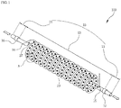
- FIG. 1 is a diagram for describing an aqueous solution sterilizing apparatus according to one embodiment of the present disclosure
- FIG. 2 is a diagram enlarging and dissecting a region A of FIG. 1 .
- an aqueous solution sterilizing apparatus 100 increases residence time of aqueous solution to secure time required for ultraviolet sterilization.
- a structure of the aqueous solution sterilizing apparatus 100 may be simplified to facilitate maintenance and reduce costs related thereto.
- the aqueous solution may be nutrient solution that is used in a hydroponics farm.
- the aqueous solution sterilizing apparatus 100 includes an aqueous solution flow tube 10 and an ultraviolet irradiator 20.
- the aqueous solution flow tube 10 is formed to block exposure of ultraviolet rays from an inside of the aqueous solution flow tube 10 to an outside thereof, and aqueous solution flows inside the aqueous solution flow tube 10.
- the aqueous solution flow tube 10 is configured with an inlet portion 11, a reaction portion 12, and an outlet portion 13.
- the inlet portion 11 is a section at which aqueous solution flows from the outside
- the reaction portion 12 is a section at which ultraviolet rays are irradiated and thus the aqueous solution is sterilized
- the outlet portion 13 is a section at which the sterilized aqueous solution flows to the outside.
- the reaction portion 12 is formed in a helical shape between the inlet portion 11 and the outlet portion 13. With such a configuration, the reaction portion 12 increases an elapsed time of the aqueous solution for flowing from the inlet portion 11 to the outlet portion 13.
- aqueous solution flowing in the inlet portion 11 flows along a helical shape tube of the reaction portion 12 of the present invention to flow to the outlet portion 13 so that the elapsed time of the aqueous solution for flowing in and out is increased.
- a stay time of the aqueous solution staying inside the reaction portion 12 may be increased and this refers that a time for ultraviolet sterilization may be more secured.
- the reaction portion 12 includes a fixing portion 14 and a through hole 15.
- the fixing portion 14 is formed at a part in contiguity with the inlet portion 11, and is fixed to one end of a flexible substrate 23, which will be described below, of the ultraviolet irradiator 20.
- the fixing portion 14 may be formed to include a protrusion of a rack shape and thus may be fixed to the one end of the flexible substrate 23.
- the fixing portion 14 may be a hook shape, but it is not limited thereto.
- the through hole 15 may be formed at a part in contiguity with the outlet portion 13, and the other end of the flexible substrate 23 may pass through the through hole 15 to be connected to an external power source. That is, the through hole 15 is a hole enabling the flexible substrate 23 to be connected to the outside.
- an O-ring may be provided at an inner circumferential surface of the through hole 15 to prevent a gap spaced apart from the flexible substrate 23.
- the aqueous solution flow tube 10 includes an inlet valve 16 and an outlet valve 17 which are provided between the inlet portion 11 and the reaction portion 12 and between the outlet portion 13 and the reaction portion 12, respectively.
- the inlet valve 16 and the outlet valve 17 may control a flow of aqueous solution.
- the inlet valve 16 may be closed to block the aqueous solution from flowing in the inlet portion 11, or may be opened to allow the aqueous solution to flow in the inlet portion 11.
- the outlet valve 17 may be closed to block the aqueous solution, which is undergone ultraviolet sterilization in the reaction portion 12, from flowing out to the outside, or may be opened to allow the aqueous solution, which is undergone ultraviolet sterilization in the reaction portion 12, to flow out to the outside.
- the inlet valve 16 and the outlet valve 17 serve as media to enable the reaction portion 12 to be attached to and detached from the inlet portion 11 and the outlet portion 13. That is, the aqueous solution flow tube 10 may be configured such that the reaction portion 12 formed between the inlet valve 16 and the outlet valve 17 is separated from the aqueous solution flow tube 10 using the inlet valve 16 and the outlet valve 17and is cleaned and replaced.
- the ultraviolet irradiator 20 is inserted inside the aqueous solution flow tube 10 and performs ultraviolet sterilization by irradiating aqueous solution with ultraviolet rays.
- the ultraviolet irradiator 20 is inserted inside the reaction portion 12 of the aqueous solution flow tube 10. Therefore, the ultraviolet irradiator 20 may be undergone a coating process to be prevented from physically coming into contact with the aqueous solution.
- the ultraviolet irradiator 20 includes a plurality of light emitting diodes (LEDs) 21, the flexible substrate 23, and a coating layer 25.
- the plurality of LEDs 21 irradiates aqueous solution with ultraviolet rays.
- the plurality of LEDs 21 emit light of ultraviolet C (UV-C) having a wavelength in the range of 100 to 280 nm.
- UV-C ultraviolet C
- the plurality of LEDs 21 may induce spontaneous generation of ozone O 3 when a wavelength is equal to or less than 200 nm, and may increase sterilization efficiency using the generated ozone.
- the plurality of LEDs 21 may obtain optimal sterilization and deodorization effects at a wavelength of 184.9 nm, that is, an ozone forming range.
- the flexible substrate 23 is connected to the plurality of LEDs 21 and supplies electric power thereto.
- the flexible substrate 23 may be connected to the plurality of LEDs 21 which are attached to one surface of the flexible substrate 23, or to the plurality of LEDs 21 which are attached to both surfaces of the flexible substrate 23.
- the flexible substrate 23 may be connected to the plurality of LEDs 21 which are attached to the both surfaces of the flexible substrate 23 to enable the plurality of LEDs 21 to irradiate ultraviolet rays in all directions.
- the flexible substrate 23 may be fine and flexible to be inserted into along an inside of the reaction portion 12.
- One end of the flexible substrate 23 is formed in an annular shape 27 and is coupled and fixed to the fixing portion 14 of the aqueous solution flow tube 10, and the other end of the flexible substrate 23 passes through the through hole 15 of the aqueous solution flow tube 10 to be connected to the external power source.
- the coating layer 25 is formed outside the plurality of LEDs 21 and the flexible substrate 23 and blocks them from coming into contact with the aqueous solution. That is, the coating layer 25 prevents generation of a short circuit due to a contact of the plurality of LEDs 21 and the flexible substrate 23 with the aqueous solution.
- the coating layer 25 may be formed of a flexible material.
- the aqueous solution sterilizing apparatus 100 may directly perform ultraviolet sterilization on the aqueous solution using the ultraviolet rays irradiated from the plurality of LEDs 21. That is, the aqueous solution sterilizing apparatus 100 may directly irradiate the aqueous solution with the ultraviolet rays because the plurality of LEDs 21 are inserted inside the reaction portion 12. Therefore, the aqueous solution sterilizing apparatus 100 may rapidly irradiate strong ultraviolet rays to maximize sterilization efficiency.
- the aqueous solution sterilizing apparatus 100 is configured with a simplified structure in which the ultraviolet irradiator 20 is inserted inside the aqueous solution flow tube 10, so that there are effects in that a size of the apparatus may be minimized and a usage amount of components may be minimized to reduce manufacturing costs.
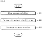
- FIG. 3 is a flow chart for describing a method for sterilizing aqueous solution according to one embodiment of the present disclosure.
- the method for sterilizing aqueous solution may directly irradiate ultraviolet rays to perform ultraviolet sterilization on aqueous solution so that sterilization efficiency may be maximized for a short time.
- aqueous solution flows in the aqueous solution sterilizing apparatus 100 through an inside of the inlet portion 11 of the aqueous solution flow tube 10.
- the aqueous solution may be nutrient solution used in a hydroponics farm.
- the aqueous solution flow tube 10 is formed in a helical shape and blocks exposure of ultraviolet rays from an inside of the aqueous solution flow tube 10 to an outside thereof.
- the aqueous solution sterilizing apparatus 100 performs ultraviolet sterilization on the aqueous solution which flows therein.
- the aqueous solution sterilizing apparatus 100 performs the ultraviolet sterilization on the aqueous solution flowing through the reaction portion 12 of the aqueous solution flow tube 10 using ultraviolet rays irradiated from the plurality of LEDs 21 that are included in the ultraviolet irradiator 20.
- the plurality of LEDs 21 are inserted inside the reaction portion 12 such that the aqueous solution sterilizing apparatus 100 directly irradiates the aqueous solution with the ultraviolet rays.
- the aqueous solution sterilizing apparatus 100 discharges the ultraviolet sterilized aqueous solution.
- the aqueous solution sterilizing apparatus 100 discharges the ultraviolet sterilized aqueous solution to the outside through the outlet portion 13 of the aqueous solution flow tube 10. At this point, the discharged aqueous solution may be provided again to and reused in the hydroponics farm, or may be drained to the outside.
- An aqueous solution sterilizing apparatus includes an aqueous solution flow tube formed in a helical shape, configured to block exposure of ultraviolet rays from an inside of the aqueous solution flow tube to an outside thereof, and through which aqueous solution flows, and an ultraviolet irradiator formed of a flexible material to be inserted inside the aqueous solution flow tube and configured to irradiate the aqueous solution with the ultraviolet rays to sterilize the aqueous solution.
Landscapes
- Health & Medical Sciences (AREA)
- Life Sciences & Earth Sciences (AREA)
- Chemical & Material Sciences (AREA)
- Engineering & Computer Science (AREA)
- Organic Chemistry (AREA)
- Water Supply & Treatment (AREA)
- Environmental & Geological Engineering (AREA)
- Toxicology (AREA)
- Hydrology & Water Resources (AREA)
- Veterinary Medicine (AREA)
- Animal Behavior & Ethology (AREA)
- Public Health (AREA)
- Epidemiology (AREA)
- General Health & Medical Sciences (AREA)
- Physical Water Treatments (AREA)
- Apparatus For Disinfection Or Sterilisation (AREA)
Abstract
Description
- This application claims priority to and the benefit of Korean Patent Application No.
10-2016-0081730 - The present invention relates to an apparatus for sterilizing aqueous solution, and more particularly, to an apparatus and a method for sterilizing aqueous solution using a flexible ultraviolet irradiator, which sterilizes aqueous solution using an ultraviolet light emitting diode (LED).
- Generally, to solve the shortage of water for cultivation and to maximize the usage of fertilizer ingredients contained in aqueous solution, it may be preferable to employ a method of cultivation in which aqueous solution that has been used once is circulated and reused.
- Here, to recirculate and reuse the aqueous solution, a control of excessive breeding of microorganisms takes precedence and this may be performed through sterilization of the aqueous solution. However, a conventional sterilization method of aqueous solution using a chemical material such as chlorine causes a problem in that growth of plants may be impeded.
- To address such a problem, a sterilization method of aqueous solution using ultraviolet rays which are used in a variety of fields has been studied, but this method also has a problem in that sterilization efficiency is varied according to an irradiation direction of the ultraviolet rays.
- Therefore, there is a need for an apparatus for sterilizing aqueous solution capable of stably providing sterilization efficiency without affecting growth of plants.
- Korean Patent Application Publication No.
2001-0099528 (November 9, 2001 - The present invention is directed to providing an apparatus and a method for sterilizing aqueous solution using a flexible ultraviolet irradiator, which are capable of increasing residence time of aqueous solution to secure time required for ultraviolet sterilization.
- The present invention is also directed to providing an apparatus and a method for sterilizing aqueous solution using a flexible ultraviolet irradiator, which are capable of simplifying a structure to facilitate maintenance and reduce costs related thereto.
- One aspect of the present invention provides an apparatus for sterilizing aqueous solution using a flexible ultraviolet irradiator, which includes an aqueous solution flow tube formed in a helical shape, configured to block exposure of ultraviolet rays from an inside of the aqueous solution flow tube to an outside thereof, and through which aqueous solution flows; and an ultraviolet irradiator formed of a flexible material to be inserted inside the aqueous solution flow tube and configured to irradiate the aqueous solution with the ultraviolet rays to sterilize the aqueous solution.
- Also, the aqueous solution flow tube may include an inlet portion configured to enable the aqueous solution to flow in; an outlet portion configured to enable the aqueous solution to flow out; a reaction portion formed in the helical shape between the inlet portion and the outlet portion and at which the aqueous solution is sterilized by the irradiation of the ultraviolet rays; and valves respectively provided between the inlet portion and the reaction portion and between the outlet portion and the reaction portion, and configured to control a flow of the aqueous solution.
- Further, the ultraviolet irradiator may include a plurality of ultraviolet light emitting diodes (LEDs) configured to irradiate the aqueous solution with the ultraviolet rays; a flexible substrate connected to the plurality of ultraviolet LEDs to supply electric power thereto, inserted inside the reaction portion, and having one end formed in an annular shape; and a coating layer formed outside the plurality of ultraviolet LEDs and the flexible substrate and configured to block the plurality of ultraviolet LEDs and the flexible substrate from coming into contact with the aqueous solution.
- In addition, the reaction portion may include a fixing portion formed at a part in contiguity with the inlet portion and coupled to the annular shape to fix one end of the flexible substrate; and a through hole formed at a part in contiguity with the outlet portion and configured to pass through and connect the other end of the flexible substrate to an external electric power source.
- Moreover, the reaction portion may be attached to and detached from the inlet portion and the outlet portion by means of the valves serving as media.
- Additionally, the aqueous solution may be nutrient solution.
- Another aspect of the present invention provides a method for sterilizing aqueous solution using a flexible ultraviolet irradiator, which includes flowing aqueous solution into an aqueous solution flow tube that is formed in a helical shape and is configured to block exposure of ultraviolet rays from an inside of the aqueous solution flow tube to an outside thereof; sterilizing the aqueous solution, which flows in the aqueous solution flow tube, using ultraviolet rays irradiated from an ultraviolet irradiator that is inserted inside the aqueous solution flow tube and is formed of a flexible material; and discharging the ultraviolet sterilized aqueous solution from the aqueous solution flow tube.
- According to the present invention, an apparatus and a method for sterilizing aqueous solution may increase residence time of aqueous solution to secure time required for ultraviolet sterilization.
- Also, a structure may be simplified to facilitate maintenance and reduce costs related thereto.
-
-
FIG. 1 is a diagram for describing an aqueous solution sterilizing apparatus according to one embodiment of the present disclosure. -
FIG. 2 is a diagram enlarging and dissecting a region A ofFIG. 1 . -
FIG. 3 is a flow chart for describing a method for sterilizing aqueous solution according to one embodiment of the present disclosure. - Hereinafter, some embodiments of the present invention will be described in detail with reference to the accompanying drawings. In giving reference numerals to components of the drawings, the same reference numerals are given to the same components although shown in a different drawing. Also, in the following description of the present invention, if a detailed description of known functions and configurations is determined to obscure the interpretation of embodiments of the present invention, the detailed description thereof will be omitted.
-
FIG. 1 is a diagram for describing an aqueous solution sterilizing apparatus according to one embodiment of the present disclosure, andFIG. 2 is a diagram enlarging and dissecting a region A ofFIG. 1 . - Referring to
FIGS. 1 and2 , an aqueoussolution sterilizing apparatus 100 increases residence time of aqueous solution to secure time required for ultraviolet sterilization. A structure of the aqueoussolution sterilizing apparatus 100 may be simplified to facilitate maintenance and reduce costs related thereto. Here, the aqueous solution may be nutrient solution that is used in a hydroponics farm. The aqueoussolution sterilizing apparatus 100 includes an aqueoussolution flow tube 10 and anultraviolet irradiator 20. - The aqueous
solution flow tube 10 is formed to block exposure of ultraviolet rays from an inside of the aqueoussolution flow tube 10 to an outside thereof, and aqueous solution flows inside the aqueoussolution flow tube 10. The aqueoussolution flow tube 10 is configured with aninlet portion 11, a reaction portion 12, and anoutlet portion 13. - The
inlet portion 11 is a section at which aqueous solution flows from the outside, the reaction portion 12 is a section at which ultraviolet rays are irradiated and thus the aqueous solution is sterilized, and theoutlet portion 13 is a section at which the sterilized aqueous solution flows to the outside. At this point, the reaction portion 12 is formed in a helical shape between theinlet portion 11 and theoutlet portion 13. With such a configuration, the reaction portion 12 increases an elapsed time of the aqueous solution for flowing from theinlet portion 11 to theoutlet portion 13. - That is, in a conventional aqueous solution flow tube formed in a straight line shape, an elapsed time of the aqueous solution for flowing in and out is short so that a time required for ultraviolet sterilization could not secured. However, the aqueous solution flowing in the
inlet portion 11 flows along a helical shape tube of the reaction portion 12 of the present invention to flow to theoutlet portion 13 so that the elapsed time of the aqueous solution for flowing in and out is increased. Through such a configuration, a stay time of the aqueous solution staying inside the reaction portion 12 may be increased and this refers that a time for ultraviolet sterilization may be more secured. - The reaction portion 12 includes a
fixing portion 14 and a throughhole 15. Thefixing portion 14 is formed at a part in contiguity with theinlet portion 11, and is fixed to one end of aflexible substrate 23, which will be described below, of theultraviolet irradiator 20. At this point, thefixing portion 14 may be formed to include a protrusion of a rack shape and thus may be fixed to the one end of theflexible substrate 23. Preferably, thefixing portion 14 may be a hook shape, but it is not limited thereto. The throughhole 15 may be formed at a part in contiguity with theoutlet portion 13, and the other end of theflexible substrate 23 may pass through the throughhole 15 to be connected to an external power source. That is, thethrough hole 15 is a hole enabling theflexible substrate 23 to be connected to the outside. At this point, an O-ring may be provided at an inner circumferential surface of the throughhole 15 to prevent a gap spaced apart from theflexible substrate 23. - The aqueous
solution flow tube 10 includes aninlet valve 16 and anoutlet valve 17 which are provided between theinlet portion 11 and the reaction portion 12 and between theoutlet portion 13 and the reaction portion 12, respectively. Theinlet valve 16 and theoutlet valve 17 may control a flow of aqueous solution. - For example, the
inlet valve 16 may be closed to block the aqueous solution from flowing in theinlet portion 11, or may be opened to allow the aqueous solution to flow in theinlet portion 11. Also, theoutlet valve 17 may be closed to block the aqueous solution, which is undergone ultraviolet sterilization in the reaction portion 12, from flowing out to the outside, or may be opened to allow the aqueous solution, which is undergone ultraviolet sterilization in the reaction portion 12, to flow out to the outside. - Also, the
inlet valve 16 and theoutlet valve 17 serve as media to enable the reaction portion 12 to be attached to and detached from theinlet portion 11 and theoutlet portion 13. That is, the aqueoussolution flow tube 10 may be configured such that the reaction portion 12 formed between theinlet valve 16 and theoutlet valve 17 is separated from the aqueoussolution flow tube 10 using theinlet valve 16 and the outlet valve 17and is cleaned and replaced. - The
ultraviolet irradiator 20 is inserted inside the aqueoussolution flow tube 10 and performs ultraviolet sterilization by irradiating aqueous solution with ultraviolet rays. In particular, theultraviolet irradiator 20 is inserted inside the reaction portion 12 of the aqueoussolution flow tube 10. Therefore, theultraviolet irradiator 20 may be undergone a coating process to be prevented from physically coming into contact with the aqueous solution. Theultraviolet irradiator 20 includes a plurality of light emitting diodes (LEDs) 21, theflexible substrate 23, and acoating layer 25. - The plurality of
LEDs 21 irradiates aqueous solution with ultraviolet rays. The plurality ofLEDs 21 emit light of ultraviolet C (UV-C) having a wavelength in the range of 100 to 280 nm. At this point, the plurality ofLEDs 21 may induce spontaneous generation of ozone O3 when a wavelength is equal to or less than 200 nm, and may increase sterilization efficiency using the generated ozone. Preferably, the plurality ofLEDs 21 may obtain optimal sterilization and deodorization effects at a wavelength of 184.9 nm, that is, an ozone forming range. - The
flexible substrate 23 is connected to the plurality ofLEDs 21 and supplies electric power thereto. At this point, theflexible substrate 23 may be connected to the plurality ofLEDs 21 which are attached to one surface of theflexible substrate 23, or to the plurality ofLEDs 21 which are attached to both surfaces of theflexible substrate 23. Preferably, theflexible substrate 23 may be connected to the plurality ofLEDs 21 which are attached to the both surfaces of theflexible substrate 23 to enable the plurality ofLEDs 21 to irradiate ultraviolet rays in all directions. Theflexible substrate 23 may be fine and flexible to be inserted into along an inside of the reaction portion 12. One end of theflexible substrate 23 is formed in anannular shape 27 and is coupled and fixed to the fixingportion 14 of the aqueoussolution flow tube 10, and the other end of theflexible substrate 23 passes through the throughhole 15 of the aqueoussolution flow tube 10 to be connected to the external power source. - The
coating layer 25 is formed outside the plurality ofLEDs 21 and theflexible substrate 23 and blocks them from coming into contact with the aqueous solution. That is, thecoating layer 25 prevents generation of a short circuit due to a contact of the plurality ofLEDs 21 and theflexible substrate 23 with the aqueous solution. Thecoating layer 25 may be formed of a flexible material. - As described above, the aqueous
solution sterilizing apparatus 100 may directly perform ultraviolet sterilization on the aqueous solution using the ultraviolet rays irradiated from the plurality ofLEDs 21. That is, the aqueoussolution sterilizing apparatus 100 may directly irradiate the aqueous solution with the ultraviolet rays because the plurality ofLEDs 21 are inserted inside the reaction portion 12. Therefore, the aqueoussolution sterilizing apparatus 100 may rapidly irradiate strong ultraviolet rays to maximize sterilization efficiency. - Also, the aqueous
solution sterilizing apparatus 100 is configured with a simplified structure in which theultraviolet irradiator 20 is inserted inside the aqueoussolution flow tube 10, so that there are effects in that a size of the apparatus may be minimized and a usage amount of components may be minimized to reduce manufacturing costs. -
FIG. 3 is a flow chart for describing a method for sterilizing aqueous solution according to one embodiment of the present disclosure. - Referring to
FIGS. 1 to 3 , the method for sterilizing aqueous solution may directly irradiate ultraviolet rays to perform ultraviolet sterilization on aqueous solution so that sterilization efficiency may be maximized for a short time. - In Operation S41, aqueous solution flows in the aqueous
solution sterilizing apparatus 100 through an inside of theinlet portion 11 of the aqueoussolution flow tube 10. At this point, the aqueous solution may be nutrient solution used in a hydroponics farm. Here, the aqueoussolution flow tube 10 is formed in a helical shape and blocks exposure of ultraviolet rays from an inside of the aqueoussolution flow tube 10 to an outside thereof. - In Operation S43, the aqueous
solution sterilizing apparatus 100 performs ultraviolet sterilization on the aqueous solution which flows therein. The aqueoussolution sterilizing apparatus 100 performs the ultraviolet sterilization on the aqueous solution flowing through the reaction portion 12 of the aqueoussolution flow tube 10 using ultraviolet rays irradiated from the plurality ofLEDs 21 that are included in theultraviolet irradiator 20. The plurality ofLEDs 21 are inserted inside the reaction portion 12 such that the aqueoussolution sterilizing apparatus 100 directly irradiates the aqueous solution with the ultraviolet rays. - In Operation S45, the aqueous
solution sterilizing apparatus 100 discharges the ultraviolet sterilized aqueous solution. The aqueoussolution sterilizing apparatus 100 discharges the ultraviolet sterilized aqueous solution to the outside through theoutlet portion 13 of the aqueoussolution flow tube 10. At this point, the discharged aqueous solution may be provided again to and reused in the hydroponics farm, or may be drained to the outside. - As described above, although the present invention has been described by way of a preferred embodiment and the accompanying drawings, it is not limited thereto, and it should be understood that numerous other changes and modifications can be devised by those skilled in the art that will fall within the spirit and scope of this invention and along with the full range of equivalents to which the appended claims are entitled.
[Description of Reference Numerals] 10: Aqueous Solution Flow Tube 11: Inlet Portion 12: Reaction Portion 13: Outlet Portion 14: Fixing Portion 15: Through Hole 16: Inlet Valve 17: Outlet Valve 20: Ultraviolet Irradiator 21: Ultraviolet Light Emitting Diode (LED) 23: Flexible Substrate 25: Coating layer 27: Annular Shape 100: Aqueous Solution Sterilizing Apparatus - Disclosed are an apparatus and a method for sterilizing aqueous solution using a flexible ultraviolet irradiator. An aqueous solution sterilizing apparatus includes an aqueous solution flow tube formed in a helical shape, configured to block exposure of ultraviolet rays from an inside of the aqueous solution flow tube to an outside thereof, and through which aqueous solution flows, and an ultraviolet irradiator formed of a flexible material to be inserted inside the aqueous solution flow tube and configured to irradiate the aqueous solution with the ultraviolet rays to sterilize the aqueous solution.
Claims (7)
- An apparatus for sterilizing aqueous solution using a flexible ultraviolet irradiator, comprising:an aqueous solution flow tube formed in a helical shape, configured to block exposure of ultraviolet rays from an inside of the aqueous solution flow tube to an outside thereof, and through which aqueous solution flows; andan ultraviolet irradiator formed of a flexible material to be inserted inside the aqueous solution flow tube and configured to irradiate the aqueous solution with the ultraviolet rays to sterilize the aqueous solution.
- The apparatus of claim 1, wherein the aqueous solution flow tube includes:an inlet portion configured to enable the aqueous solution to flow in;an outlet portion configured to enable the aqueous solution to flow out;a reaction portion formed in the helical shape between the inlet portion and the outlet portion and at which the aqueous solution is sterilized by the irradiation of the ultraviolet rays; andvalves respectively provided between the inlet portion and the reaction portion and between the outlet portion and the reaction portion, and configured to control a flow of the aqueous solution.
- The apparatus of claim 2, wherein the ultraviolet irradiator includes:a plurality of ultraviolet light emitting diodes (LEDs) configured to irradiate the aqueous solution with the ultraviolet rays;a flexible substrate connected to the plurality of ultraviolet LEDs to supply electric power thereto, inserted inside the reaction portion, and having one end formed in an annular shape; anda coating layer formed outside the plurality of ultraviolet LEDs and the flexible substrate and configured to block the plurality of ultraviolet LEDs and the flexible substrate from coming into contact with the aqueous solution.
- The apparatus of claim 3, wherein the reaction portion includes:a fixing portion formed at a part in contiguity with the inlet portion and coupled to the annular shape to fix one end of the flexible substrate; anda through hole formed at a part in contiguity with the outlet portion and configured to pass through and connect the other end of the flexible substrate to an external electric power source.
- The apparatus of claim 2, wherein the reaction portion is attached to and detached from the inlet portion and the outlet portion by means of the valves serving as media.
- The apparatus of claim 1, wherein the aqueous solution is nutrient solution.
- A method for sterilizing aqueous solution using a flexible ultraviolet irradiator, comprising:flowing aqueous solution into an aqueous solution flow tube that is formed in a helical shape and is configured to block exposure of ultraviolet rays from an inside of the aqueous solution flow tube to an outside thereof;sterilizing the aqueous solution, which flows in the aqueous solution flow tube, using ultraviolet rays irradiated from an ultraviolet irradiator that is inserted inside the aqueous solution flow tube and is formed of a flexible material; anddischarging the ultraviolet sterilized aqueous solution from the aqueous solution flow tube.
Applications Claiming Priority (1)
| Application Number | Priority Date | Filing Date | Title |
|---|---|---|---|
| KR1020160081730A KR101803706B1 (en) | 2016-06-29 | 2016-06-29 | Aqueous solution sterilizers and method using flexible UV irradiator |
Publications (2)
| Publication Number | Publication Date |
|---|---|
| EP3263137A1 true EP3263137A1 (en) | 2018-01-03 |
| EP3263137B1 EP3263137B1 (en) | 2021-08-18 |
Family
ID=57144902
Family Applications (1)
| Application Number | Title | Priority Date | Filing Date |
|---|---|---|---|
| EP16194299.0A Active EP3263137B1 (en) | 2016-06-29 | 2016-10-18 | Apparatus and method for sterilizing aqueous solution using flexible ultraviolet irradiator |
Country Status (2)
| Country | Link |
|---|---|
| EP (1) | EP3263137B1 (en) |
| KR (1) | KR101803706B1 (en) |
Cited By (1)
| Publication number | Priority date | Publication date | Assignee | Title |
|---|---|---|---|---|
| JPWO2023058376A1 (en) * | 2021-10-05 | 2023-04-13 |
Citations (5)
| Publication number | Priority date | Publication date | Assignee | Title |
|---|---|---|---|---|
| KR20010099528A (en) | 2000-04-27 | 2001-11-09 | 이인화 | Nutrient solution disinfection and recycling system by utilizing ultraviolet light and photocatalyst effect |
| US20060131246A1 (en) * | 2004-12-21 | 2006-06-22 | Ranco Incorporated Of Delaware | Water purification system utilizing a plurality of ultraviolet light emitting diodes and associated method of use |
| KR100718676B1 (en) * | 2004-11-17 | 2007-05-18 | 김태규 | Water Disinfection Cleaner Using Photocatalyst Beads |
| WO2012021051A1 (en) * | 2010-08-10 | 2012-02-16 | Andres Abelino Choza Romero | Apparatus for disinfecting liquids by means of ultraviolet light |
| US20120261319A1 (en) * | 2011-04-14 | 2012-10-18 | Empire Technology Development Llc | Ultraviolet water sterilization |
-
2016
- 2016-06-29 KR KR1020160081730A patent/KR101803706B1/en active Active
- 2016-10-18 EP EP16194299.0A patent/EP3263137B1/en active Active
Patent Citations (5)
| Publication number | Priority date | Publication date | Assignee | Title |
|---|---|---|---|---|
| KR20010099528A (en) | 2000-04-27 | 2001-11-09 | 이인화 | Nutrient solution disinfection and recycling system by utilizing ultraviolet light and photocatalyst effect |
| KR100718676B1 (en) * | 2004-11-17 | 2007-05-18 | 김태규 | Water Disinfection Cleaner Using Photocatalyst Beads |
| US20060131246A1 (en) * | 2004-12-21 | 2006-06-22 | Ranco Incorporated Of Delaware | Water purification system utilizing a plurality of ultraviolet light emitting diodes and associated method of use |
| WO2012021051A1 (en) * | 2010-08-10 | 2012-02-16 | Andres Abelino Choza Romero | Apparatus for disinfecting liquids by means of ultraviolet light |
| US20120261319A1 (en) * | 2011-04-14 | 2012-10-18 | Empire Technology Development Llc | Ultraviolet water sterilization |
Cited By (1)
| Publication number | Priority date | Publication date | Assignee | Title |
|---|---|---|---|---|
| JPWO2023058376A1 (en) * | 2021-10-05 | 2023-04-13 |
Also Published As
| Publication number | Publication date |
|---|---|
| KR101803706B1 (en) | 2017-12-04 |
| EP3263137B1 (en) | 2021-08-18 |
Similar Documents
| Publication | Publication Date | Title |
|---|---|---|
| US9061082B2 (en) | Ultraviolet-based sterilization | |
| US20160052802A1 (en) | Water purification apparatus | |
| JP4809482B2 (en) | Water disinfection device | |
| KR20170097063A (en) | Plasma activated water | |
| US20140328720A1 (en) | Purification device and purification method | |
| JP2014233712A (en) | Ultraviolet sterilization device | |
| KR101896964B1 (en) | Water treatment apparatus using air bubbles ultrasonic waves and system using the same | |
| WO2017030456A2 (en) | Reprocessing apparatus and a method of reprocessing a load in a reprocessing apparatus | |
| CN107921159A (en) | Sterilizing unit | |
| US20110220813A1 (en) | Ultraviolet water treatment apparatus | |
| EP3263137B1 (en) | Apparatus and method for sterilizing aqueous solution using flexible ultraviolet irradiator | |
| KR20150052379A (en) | Bidet apparatus | |
| KR102038961B1 (en) | Shower apparatus using UV-LED | |
| AU2014319795B2 (en) | Ultraviolet irradiation device | |
| CN111032577A (en) | water treatment equipment | |
| KR20220092076A (en) | Hydroponics cultivation apparatus using aqua plasma method | |
| KR101795508B1 (en) | Water treating apparatus | |
| KR102381503B1 (en) | Uvc led reactor for flowing water sterilization | |
| JP5929192B2 (en) | Purification device and hydroponics system using the same | |
| JP6651569B2 (en) | Water purification equipment | |
| KR102364990B1 (en) | Uvc led reactor for flowing water sterilization | |
| KR101017272B1 (en) | Waste nutrient processing device and nutrient solution cultivation device using the same | |
| KR20160017411A (en) | Storage apparatus for fruits and vegetables | |
| KR20120140502A (en) | Water treatment system using a led-uv lamp and a photocatalyst | |
| US12391581B2 (en) | Apparatus for sterilizing a liquid |
Legal Events
| Date | Code | Title | Description |
|---|---|---|---|
| PUAI | Public reference made under article 153(3) epc to a published international application that has entered the european phase |
Free format text: ORIGINAL CODE: 0009012 |
|
| STAA | Information on the status of an ep patent application or granted ep patent |
Free format text: STATUS: REQUEST FOR EXAMINATION WAS MADE |
|
| 17P | Request for examination filed |
Effective date: 20161018 |
|
| AK | Designated contracting states |
Kind code of ref document: A1 Designated state(s): AL AT BE BG CH CY CZ DE DK EE ES FI FR GB GR HR HU IE IS IT LI LT LU LV MC MK MT NL NO PL PT RO RS SE SI SK SM TR |
|
| AX | Request for extension of the european patent |
Extension state: BA ME |
|
| STAA | Information on the status of an ep patent application or granted ep patent |
Free format text: STATUS: EXAMINATION IS IN PROGRESS |
|
| 17Q | First examination report despatched |
Effective date: 20200518 |
|
| GRAP | Despatch of communication of intention to grant a patent |
Free format text: ORIGINAL CODE: EPIDOSNIGR1 |
|
| STAA | Information on the status of an ep patent application or granted ep patent |
Free format text: STATUS: GRANT OF PATENT IS INTENDED |
|
| INTG | Intention to grant announced |
Effective date: 20210423 |
|
| RIN1 | Information on inventor provided before grant (corrected) |
Inventor name: PARK, JUNWOO Inventor name: LEE, JUYEON Inventor name: OH, SANGROK Inventor name: NHO, CHUWON Inventor name: LEE, JUYOUNG Inventor name: YANG, JUNGSEOK Inventor name: LEE, TAIKJIN Inventor name: LEE, TAEKSUNG Inventor name: KIM, HYOUNGSEOK Inventor name: KWON, MANJAE |
|
| GRAS | Grant fee paid |
Free format text: ORIGINAL CODE: EPIDOSNIGR3 |
|
| GRAA | (expected) grant |
Free format text: ORIGINAL CODE: 0009210 |
|
| STAA | Information on the status of an ep patent application or granted ep patent |
Free format text: STATUS: THE PATENT HAS BEEN GRANTED |
|
| AK | Designated contracting states |
Kind code of ref document: B1 Designated state(s): AL AT BE BG CH CY CZ DE DK EE ES FI FR GB GR HR HU IE IS IT LI LT LU LV MC MK MT NL NO PL PT RO RS SE SI SK SM TR |
|
| REG | Reference to a national code |
Ref country code: GB Ref legal event code: FG4D |
|
| REG | Reference to a national code |
Ref country code: CH Ref legal event code: EP |
|
| REG | Reference to a national code |
Ref country code: DE Ref legal event code: R096 Ref document number: 602016062302 Country of ref document: DE |
|
| REG | Reference to a national code |
Ref country code: IE Ref legal event code: FG4D Ref country code: AT Ref legal event code: REF Ref document number: 1421039 Country of ref document: AT Kind code of ref document: T Effective date: 20210915 |
|
| REG | Reference to a national code |
Ref country code: LT Ref legal event code: MG9D |
|
| REG | Reference to a national code |
Ref country code: NL Ref legal event code: MP Effective date: 20210818 |
|
| REG | Reference to a national code |
Ref country code: AT Ref legal event code: MK05 Ref document number: 1421039 Country of ref document: AT Kind code of ref document: T Effective date: 20210818 |
|
| PG25 | Lapsed in a contracting state [announced via postgrant information from national office to epo] |
Ref country code: SE Free format text: LAPSE BECAUSE OF FAILURE TO SUBMIT A TRANSLATION OF THE DESCRIPTION OR TO PAY THE FEE WITHIN THE PRESCRIBED TIME-LIMIT Effective date: 20210818 Ref country code: RS Free format text: LAPSE BECAUSE OF FAILURE TO SUBMIT A TRANSLATION OF THE DESCRIPTION OR TO PAY THE FEE WITHIN THE PRESCRIBED TIME-LIMIT Effective date: 20210818 Ref country code: HR Free format text: LAPSE BECAUSE OF FAILURE TO SUBMIT A TRANSLATION OF THE DESCRIPTION OR TO PAY THE FEE WITHIN THE PRESCRIBED TIME-LIMIT Effective date: 20210818 Ref country code: LT Free format text: LAPSE BECAUSE OF FAILURE TO SUBMIT A TRANSLATION OF THE DESCRIPTION OR TO PAY THE FEE WITHIN THE PRESCRIBED TIME-LIMIT Effective date: 20210818 Ref country code: AT Free format text: LAPSE BECAUSE OF FAILURE TO SUBMIT A TRANSLATION OF THE DESCRIPTION OR TO PAY THE FEE WITHIN THE PRESCRIBED TIME-LIMIT Effective date: 20210818 Ref country code: BG Free format text: LAPSE BECAUSE OF FAILURE TO SUBMIT A TRANSLATION OF THE DESCRIPTION OR TO PAY THE FEE WITHIN THE PRESCRIBED TIME-LIMIT Effective date: 20211118 Ref country code: NO Free format text: LAPSE BECAUSE OF FAILURE TO SUBMIT A TRANSLATION OF THE DESCRIPTION OR TO PAY THE FEE WITHIN THE PRESCRIBED TIME-LIMIT Effective date: 20211118 Ref country code: PT Free format text: LAPSE BECAUSE OF FAILURE TO SUBMIT A TRANSLATION OF THE DESCRIPTION OR TO PAY THE FEE WITHIN THE PRESCRIBED TIME-LIMIT Effective date: 20211220 Ref country code: ES Free format text: LAPSE BECAUSE OF FAILURE TO SUBMIT A TRANSLATION OF THE DESCRIPTION OR TO PAY THE FEE WITHIN THE PRESCRIBED TIME-LIMIT Effective date: 20210818 Ref country code: FI Free format text: LAPSE BECAUSE OF FAILURE TO SUBMIT A TRANSLATION OF THE DESCRIPTION OR TO PAY THE FEE WITHIN THE PRESCRIBED TIME-LIMIT Effective date: 20210818 |
|
| PG25 | Lapsed in a contracting state [announced via postgrant information from national office to epo] |
Ref country code: PL Free format text: LAPSE BECAUSE OF FAILURE TO SUBMIT A TRANSLATION OF THE DESCRIPTION OR TO PAY THE FEE WITHIN THE PRESCRIBED TIME-LIMIT Effective date: 20210818 Ref country code: LV Free format text: LAPSE BECAUSE OF FAILURE TO SUBMIT A TRANSLATION OF THE DESCRIPTION OR TO PAY THE FEE WITHIN THE PRESCRIBED TIME-LIMIT Effective date: 20210818 Ref country code: GR Free format text: LAPSE BECAUSE OF FAILURE TO SUBMIT A TRANSLATION OF THE DESCRIPTION OR TO PAY THE FEE WITHIN THE PRESCRIBED TIME-LIMIT Effective date: 20211119 |
|
| PG25 | Lapsed in a contracting state [announced via postgrant information from national office to epo] |
Ref country code: NL Free format text: LAPSE BECAUSE OF FAILURE TO SUBMIT A TRANSLATION OF THE DESCRIPTION OR TO PAY THE FEE WITHIN THE PRESCRIBED TIME-LIMIT Effective date: 20210818 |
|
| PG25 | Lapsed in a contracting state [announced via postgrant information from national office to epo] |
Ref country code: DK Free format text: LAPSE BECAUSE OF FAILURE TO SUBMIT A TRANSLATION OF THE DESCRIPTION OR TO PAY THE FEE WITHIN THE PRESCRIBED TIME-LIMIT Effective date: 20210818 |
|
| REG | Reference to a national code |
Ref country code: DE Ref legal event code: R097 Ref document number: 602016062302 Country of ref document: DE |
|
| REG | Reference to a national code |
Ref country code: CH Ref legal event code: PL |
|
| PG25 | Lapsed in a contracting state [announced via postgrant information from national office to epo] |
Ref country code: SM Free format text: LAPSE BECAUSE OF FAILURE TO SUBMIT A TRANSLATION OF THE DESCRIPTION OR TO PAY THE FEE WITHIN THE PRESCRIBED TIME-LIMIT Effective date: 20210818 Ref country code: SK Free format text: LAPSE BECAUSE OF FAILURE TO SUBMIT A TRANSLATION OF THE DESCRIPTION OR TO PAY THE FEE WITHIN THE PRESCRIBED TIME-LIMIT Effective date: 20210818 Ref country code: RO Free format text: LAPSE BECAUSE OF FAILURE TO SUBMIT A TRANSLATION OF THE DESCRIPTION OR TO PAY THE FEE WITHIN THE PRESCRIBED TIME-LIMIT Effective date: 20210818 Ref country code: EE Free format text: LAPSE BECAUSE OF FAILURE TO SUBMIT A TRANSLATION OF THE DESCRIPTION OR TO PAY THE FEE WITHIN THE PRESCRIBED TIME-LIMIT Effective date: 20210818 Ref country code: CZ Free format text: LAPSE BECAUSE OF FAILURE TO SUBMIT A TRANSLATION OF THE DESCRIPTION OR TO PAY THE FEE WITHIN THE PRESCRIBED TIME-LIMIT Effective date: 20210818 Ref country code: AL Free format text: LAPSE BECAUSE OF FAILURE TO SUBMIT A TRANSLATION OF THE DESCRIPTION OR TO PAY THE FEE WITHIN THE PRESCRIBED TIME-LIMIT Effective date: 20210818 |
|
| REG | Reference to a national code |
Ref country code: BE Ref legal event code: MM Effective date: 20211031 |
|
| PLBE | No opposition filed within time limit |
Free format text: ORIGINAL CODE: 0009261 |
|
| STAA | Information on the status of an ep patent application or granted ep patent |
Free format text: STATUS: NO OPPOSITION FILED WITHIN TIME LIMIT |
|
| PG25 | Lapsed in a contracting state [announced via postgrant information from national office to epo] |
Ref country code: MC Free format text: LAPSE BECAUSE OF FAILURE TO SUBMIT A TRANSLATION OF THE DESCRIPTION OR TO PAY THE FEE WITHIN THE PRESCRIBED TIME-LIMIT Effective date: 20210818 |
|
| 26N | No opposition filed |
Effective date: 20220519 |
|
| PG25 | Lapsed in a contracting state [announced via postgrant information from national office to epo] |
Ref country code: LU Free format text: LAPSE BECAUSE OF NON-PAYMENT OF DUE FEES Effective date: 20211018 Ref country code: IT Free format text: LAPSE BECAUSE OF FAILURE TO SUBMIT A TRANSLATION OF THE DESCRIPTION OR TO PAY THE FEE WITHIN THE PRESCRIBED TIME-LIMIT Effective date: 20210818 Ref country code: BE Free format text: LAPSE BECAUSE OF NON-PAYMENT OF DUE FEES Effective date: 20211031 |
|
| PG25 | Lapsed in a contracting state [announced via postgrant information from national office to epo] |
Ref country code: SI Free format text: LAPSE BECAUSE OF FAILURE TO SUBMIT A TRANSLATION OF THE DESCRIPTION OR TO PAY THE FEE WITHIN THE PRESCRIBED TIME-LIMIT Effective date: 20210818 Ref country code: LI Free format text: LAPSE BECAUSE OF NON-PAYMENT OF DUE FEES Effective date: 20211031 Ref country code: CH Free format text: LAPSE BECAUSE OF NON-PAYMENT OF DUE FEES Effective date: 20211031 |
|
| PG25 | Lapsed in a contracting state [announced via postgrant information from national office to epo] |
Ref country code: IE Free format text: LAPSE BECAUSE OF NON-PAYMENT OF DUE FEES Effective date: 20211018 |
|
| PG25 | Lapsed in a contracting state [announced via postgrant information from national office to epo] |
Ref country code: HU Free format text: LAPSE BECAUSE OF FAILURE TO SUBMIT A TRANSLATION OF THE DESCRIPTION OR TO PAY THE FEE WITHIN THE PRESCRIBED TIME-LIMIT; INVALID AB INITIO Effective date: 20161018 |
|
| PG25 | Lapsed in a contracting state [announced via postgrant information from national office to epo] |
Ref country code: CY Free format text: LAPSE BECAUSE OF FAILURE TO SUBMIT A TRANSLATION OF THE DESCRIPTION OR TO PAY THE FEE WITHIN THE PRESCRIBED TIME-LIMIT Effective date: 20210818 |
|
| PG25 | Lapsed in a contracting state [announced via postgrant information from national office to epo] |
Ref country code: MK Free format text: LAPSE BECAUSE OF FAILURE TO SUBMIT A TRANSLATION OF THE DESCRIPTION OR TO PAY THE FEE WITHIN THE PRESCRIBED TIME-LIMIT Effective date: 20210818 |
|
| PG25 | Lapsed in a contracting state [announced via postgrant information from national office to epo] |
Ref country code: MT Free format text: LAPSE BECAUSE OF FAILURE TO SUBMIT A TRANSLATION OF THE DESCRIPTION OR TO PAY THE FEE WITHIN THE PRESCRIBED TIME-LIMIT Effective date: 20210818 |
|
| PGFP | Annual fee paid to national office [announced via postgrant information from national office to epo] |
Ref country code: GB Payment date: 20240920 Year of fee payment: 9 |
|
| PGFP | Annual fee paid to national office [announced via postgrant information from national office to epo] |
Ref country code: FR Payment date: 20240925 Year of fee payment: 9 |
|
| PGFP | Annual fee paid to national office [announced via postgrant information from national office to epo] |
Ref country code: DE Payment date: 20240920 Year of fee payment: 9 |
|
| PG25 | Lapsed in a contracting state [announced via postgrant information from national office to epo] |
Ref country code: TR Free format text: LAPSE BECAUSE OF FAILURE TO SUBMIT A TRANSLATION OF THE DESCRIPTION OR TO PAY THE FEE WITHIN THE PRESCRIBED TIME-LIMIT Effective date: 20210818 |