EP3261891B1 - Method and apparatuses for detecting faults in vehicle control systems - Google Patents
Method and apparatuses for detecting faults in vehicle control systems Download PDFInfo
- Publication number
- EP3261891B1 EP3261891B1 EP16707695.9A EP16707695A EP3261891B1 EP 3261891 B1 EP3261891 B1 EP 3261891B1 EP 16707695 A EP16707695 A EP 16707695A EP 3261891 B1 EP3261891 B1 EP 3261891B1
- Authority
- EP
- European Patent Office
- Prior art keywords
- functional units
- traversal value
- value
- functional unit
- functional
- Prior art date
- Legal status (The legal status is an assumption and is not a legal conclusion. Google has not performed a legal analysis and makes no representation as to the accuracy of the status listed.)
- Active
Links
Images



Classifications
-
- G—PHYSICS
- G07—CHECKING-DEVICES
- G07C—TIME OR ATTENDANCE REGISTERS; REGISTERING OR INDICATING THE WORKING OF MACHINES; GENERATING RANDOM NUMBERS; VOTING OR LOTTERY APPARATUS; ARRANGEMENTS, SYSTEMS OR APPARATUS FOR CHECKING NOT PROVIDED FOR ELSEWHERE
- G07C5/00—Registering or indicating the working of vehicles
- G07C5/08—Registering or indicating performance data other than driving, working, idle, or waiting time, with or without registering driving, working, idle or waiting time
- G07C5/0808—Diagnosing performance data
-
- B—PERFORMING OPERATIONS; TRANSPORTING
- B60—VEHICLES IN GENERAL
- B60W—CONJOINT CONTROL OF VEHICLE SUB-UNITS OF DIFFERENT TYPE OR DIFFERENT FUNCTION; CONTROL SYSTEMS SPECIALLY ADAPTED FOR HYBRID VEHICLES; ROAD VEHICLE DRIVE CONTROL SYSTEMS FOR PURPOSES NOT RELATED TO THE CONTROL OF A PARTICULAR SUB-UNIT
- B60W50/00—Details of control systems for road vehicle drive control not related to the control of a particular sub-unit, e.g. process diagnostic or vehicle driver interfaces
- B60W50/02—Ensuring safety in case of control system failures, e.g. by diagnosing, circumventing or fixing failures
- B60W50/0205—Diagnosing or detecting failures; Failure detection models
-
- B—PERFORMING OPERATIONS; TRANSPORTING
- B60—VEHICLES IN GENERAL
- B60W—CONJOINT CONTROL OF VEHICLE SUB-UNITS OF DIFFERENT TYPE OR DIFFERENT FUNCTION; CONTROL SYSTEMS SPECIALLY ADAPTED FOR HYBRID VEHICLES; ROAD VEHICLE DRIVE CONTROL SYSTEMS FOR PURPOSES NOT RELATED TO THE CONTROL OF A PARTICULAR SUB-UNIT
- B60W10/00—Conjoint control of vehicle sub-units of different type or different function
-
- B—PERFORMING OPERATIONS; TRANSPORTING
- B60—VEHICLES IN GENERAL
- B60W—CONJOINT CONTROL OF VEHICLE SUB-UNITS OF DIFFERENT TYPE OR DIFFERENT FUNCTION; CONTROL SYSTEMS SPECIALLY ADAPTED FOR HYBRID VEHICLES; ROAD VEHICLE DRIVE CONTROL SYSTEMS FOR PURPOSES NOT RELATED TO THE CONTROL OF A PARTICULAR SUB-UNIT
- B60W50/00—Details of control systems for road vehicle drive control not related to the control of a particular sub-unit, e.g. process diagnostic or vehicle driver interfaces
- B60W50/04—Monitoring the functioning of the control system
-
- G—PHYSICS
- G01—MEASURING; TESTING
- G01M—TESTING STATIC OR DYNAMIC BALANCE OF MACHINES OR STRUCTURES; TESTING OF STRUCTURES OR APPARATUS, NOT OTHERWISE PROVIDED FOR
- G01M17/00—Testing of vehicles
-
- G—PHYSICS
- G06—COMPUTING OR CALCULATING; COUNTING
- G06F—ELECTRIC DIGITAL DATA PROCESSING
- G06F11/00—Error detection; Error correction; Monitoring
- G06F11/22—Detection or location of defective computer hardware by testing during standby operation or during idle time, e.g. start-up testing
-
- G—PHYSICS
- G07—CHECKING-DEVICES
- G07C—TIME OR ATTENDANCE REGISTERS; REGISTERING OR INDICATING THE WORKING OF MACHINES; GENERATING RANDOM NUMBERS; VOTING OR LOTTERY APPARATUS; ARRANGEMENTS, SYSTEMS OR APPARATUS FOR CHECKING NOT PROVIDED FOR ELSEWHERE
- G07C5/00—Registering or indicating the working of vehicles
- G07C5/08—Registering or indicating performance data other than driving, working, idle, or waiting time, with or without registering driving, working, idle or waiting time
- G07C5/0841—Registering performance data
-
- B—PERFORMING OPERATIONS; TRANSPORTING
- B60—VEHICLES IN GENERAL
- B60W—CONJOINT CONTROL OF VEHICLE SUB-UNITS OF DIFFERENT TYPE OR DIFFERENT FUNCTION; CONTROL SYSTEMS SPECIALLY ADAPTED FOR HYBRID VEHICLES; ROAD VEHICLE DRIVE CONTROL SYSTEMS FOR PURPOSES NOT RELATED TO THE CONTROL OF A PARTICULAR SUB-UNIT
- B60W50/00—Details of control systems for road vehicle drive control not related to the control of a particular sub-unit, e.g. process diagnostic or vehicle driver interfaces
- B60W2050/0001—Details of the control system
- B60W2050/0002—Automatic control, details of type of controller or control system architecture
- B60W2050/0004—In digital systems, e.g. discrete-time systems involving sampling
- B60W2050/0006—Digital architecture hierarchy
-
- B—PERFORMING OPERATIONS; TRANSPORTING
- B60—VEHICLES IN GENERAL
- B60W—CONJOINT CONTROL OF VEHICLE SUB-UNITS OF DIFFERENT TYPE OR DIFFERENT FUNCTION; CONTROL SYSTEMS SPECIALLY ADAPTED FOR HYBRID VEHICLES; ROAD VEHICLE DRIVE CONTROL SYSTEMS FOR PURPOSES NOT RELATED TO THE CONTROL OF A PARTICULAR SUB-UNIT
- B60W50/00—Details of control systems for road vehicle drive control not related to the control of a particular sub-unit, e.g. process diagnostic or vehicle driver interfaces
- B60W50/02—Ensuring safety in case of control system failures, e.g. by diagnosing, circumventing or fixing failures
- B60W50/0205—Diagnosing or detecting failures; Failure detection models
- B60W2050/021—Means for detecting failure or malfunction
-
- B—PERFORMING OPERATIONS; TRANSPORTING
- B60—VEHICLES IN GENERAL
- B60W—CONJOINT CONTROL OF VEHICLE SUB-UNITS OF DIFFERENT TYPE OR DIFFERENT FUNCTION; CONTROL SYSTEMS SPECIALLY ADAPTED FOR HYBRID VEHICLES; ROAD VEHICLE DRIVE CONTROL SYSTEMS FOR PURPOSES NOT RELATED TO THE CONTROL OF A PARTICULAR SUB-UNIT
- B60W50/00—Details of control systems for road vehicle drive control not related to the control of a particular sub-unit, e.g. process diagnostic or vehicle driver interfaces
- B60W50/02—Ensuring safety in case of control system failures, e.g. by diagnosing, circumventing or fixing failures
- B60W50/0205—Diagnosing or detecting failures; Failure detection models
- B60W2050/0215—Sensor drifts or sensor failures
-
- B—PERFORMING OPERATIONS; TRANSPORTING
- B60—VEHICLES IN GENERAL
- B60W—CONJOINT CONTROL OF VEHICLE SUB-UNITS OF DIFFERENT TYPE OR DIFFERENT FUNCTION; CONTROL SYSTEMS SPECIALLY ADAPTED FOR HYBRID VEHICLES; ROAD VEHICLE DRIVE CONTROL SYSTEMS FOR PURPOSES NOT RELATED TO THE CONTROL OF A PARTICULAR SUB-UNIT
- B60W50/00—Details of control systems for road vehicle drive control not related to the control of a particular sub-unit, e.g. process diagnostic or vehicle driver interfaces
- B60W50/04—Monitoring the functioning of the control system
- B60W2050/041—Built in Test Equipment [BITE]
-
- G—PHYSICS
- G06—COMPUTING OR CALCULATING; COUNTING
- G06F—ELECTRIC DIGITAL DATA PROCESSING
- G06F7/00—Methods or arrangements for processing data by operating upon the order or content of the data handled
- G06F7/02—Comparing digital values
-
- H—ELECTRICITY
- H04—ELECTRIC COMMUNICATION TECHNIQUE
- H04L—TRANSMISSION OF DIGITAL INFORMATION, e.g. TELEGRAPHIC COMMUNICATION
- H04L67/00—Network arrangements or protocols for supporting network services or applications
- H04L67/01—Protocols
- H04L67/12—Protocols specially adapted for proprietary or special-purpose networking environments, e.g. medical networks, sensor networks, networks in vehicles or remote metering networks
Definitions
- the invention relates to vehicle control systems, in particular methods and systems for detecting faults in vehicle control systems.
- Modern vehicle control systems are comprised of a network of systems, subsystems and controllers interacting to control the various components of the vehicle.
- a vehicle control system could comprise subsystems associated with a domain of features of the vehicle such as vehicle dynamics.
- Each of these subsystems may comprise one or more electronic control units (ECUs) which are associated with a feature of the domain, for example the vehicle dynamics subsystem may comprise an ECU relating to braking.
- the subsystems also comprise functional units that are related to that domain subsystem.
- a functional unit could for example be a brake actuation sensor.
- the functional units are often interconnected which makes detecting and locating faults rapidly a challenge.
- vehicle control systems comprising numerous subsystems communicating and controlling various aspects of the vehicle
- testing and validation of large electronic control systems is of significant importance.
- the increasing numbers of features in vehicle control systems has in turn increased the proportion of vehicle production costs associated with control systems.
- a fault detection method and system for vehicle control system being able to detect faults efficiently and effectively during production and development would thus decrease production costs and increase vehicle reliability.
- the present invention preferably seeks to mitigate or eliminate one or more of the above-identified deficiencies in the art singly or in any combination and solves at least the above mentioned problems by providing a solution in accordance with the independent claims set forth below.
- a method for detecting faults in a vehicle control system comprising functional units having an associated unique prime number label.
- the method comprises calling each of the functional units, the call comprising a readable and updateable integer traversal value, and in case the functional unit is operating correctly, updating the traversal value to be the product of the value in the call and the label of the currently called functional unit, and in the case of a fault, not updating the traversal value; and determining from the traversal value if any functional units are faulty by a comparison with an expected traversal value, and, in the case that the traversal value is not equivalent to the expected traversal value, determining which functional units are faulty by a unique prime factorization algorithm.
- the vehicle control system comprises two or more functional units.
- the unique prime label may be associated according to the ascending sequence of prime numbers starting at the number 2.
- faulty units are detected by comparing the traversal value with an expected traversal value, if the stored value is not equal to the expected value then the missing prime factor(s) are determined through a unique prime factorization algorithm.
- the method may further comprise accessing a list, the list associating a descriptor of a functional unit to a unique prime number label, to determine the descriptor of any faulty functional units.
- the vehicle control system further comprises subsystems being associated with vehicle hardware, wherein the subsystems comprise the functional units, the method further comprising associating the functional units with the comprising subsystem.
- a functional unit subset may be selected from the functional units comprised in the vehicle control system, such that only a subset of related or associated functional units are tested.
- a controller for detecting faults in a vehicle control system comprising functional units.
- Each of the functional units of the vehicle control system are assigned a unique prime number from the ascending sequence of prime numbers starting at 2.
- the controller for detecting faults comprises a means of calling the functional units wherein the call to the functional unit comprises, a readable and updateable integer traversal value, a means of, in case the functional unit is operating correctly, updating the traversal value to be the product of the value in the call and the label of the currently called functional unit, and in the case of a fault, not updating the traversal value; and a processing unit programmed to determine which if any of the functional units are faulty by a unique prime factorization algorithm.
- the processing unit is programmed to detect any faulty functional units by comparing the product stored in the detection signal with an expected traversal value, if the stored value is not equal to the expected traversal value then the missing prime factor(s) are determined through a unique prime factorization algorithm.
- a method for providing at least one implemented unit comprises assigning a unique prime label to a functional unit, and wherein the unique prime label is assigned from the ascending sequence of prime numbers starting at the number 2.
- a system comprising a hardware component of a vehicle being associated with one or more functional units and a controller according to the third aspect.
- the following description of the invention concerns methods, controllers and systems for detecting faults in vehicle control systems comprising functional units having an associated unique prime number label.
- the functional units may be associated with specific components of a vehicle. For instance, the functional units may be associated with those directly related to the movement of the vehicle, such as a break actuation sensor.
- the functional units may also be associated with components related to ancillary aspects of the vehicle such as a seat warming controller.
- controllers and systems faults in one or more individual functional units can be detected and located efficiently and effectively.
- the vehicles control system can comprise one or more functional units, such as two or more. Functional units may be software implemented.
- Functional units are assigned a unique prime number label to enable identification.
- Such method 20 is generally depicted in Fig. 2 .
- the unique prime number label can be assigned 24 to the functional unit during or prior to run-time, and preferably after accessing the functional unit 22.
- the unique prime number label acts as an identifier of the functional unit throughout the fault detection method.
- An ideal method of assigning the unique prime number labels is to assign labels from the ascending sequence of prime numbers starting from the prime number 2. That is, the unique prime number label of the first functional unit is assigned the number 2, the unique prime number label of the second functional unit is assigned the number 3, the unique prime number label of the third functional unit 5 and so on.
- the prime number 1 is preferably not used as a unique prime number label of a functional unit.
- the fault detection method 10 is schematically shown in Fig. 1 .
- the call 12 to the functional unit comprises a traversal value.
- the traversal value is an integer value which can be both read and updated by the respective receiving functional unit.
- the traversal value which is provided 14 to the first functional unit during fault detection is the value 1.
- the receiving functional unit can update 16 the traversal value to be equal to the product of the traversal value comprised in the call and the unique prime label of the currently called functional unit.
- the multiplication results in an integer product which is the product of the receiving functional unit's unique prime label and the product of all functional units previously called that were without error.
- the traversal value is then updated to be equal to the product.
- a faulty functional unit which is an error state will not update the traversal value.
- the traversal value will thus be unchanged by a functional unit which is faulty.
- the traversal value is then passed in a call to the next functional unit.
- the next functional unit repeats the multiplication process described above with its own unique prime number label.
- the traversal value can be compared to an expected traversal value.
- a unique prime factorisation algorithm is used.
- the traversal value After being passed to one or more functional units the traversal value is compared to an expected traversal value.
- the traversal value is first divided by the lowest prime factor of the traversal value. If the quotient is not a prime number then the quotient is subsequently divided by the next lowest prime. This process is repeated for the subsequent prime factors until the quotient is a prime number.
- the process is stopped and the set of prime divisors is compared to the expected set of unique prime labels.
- the unique prime labels which are missing from the set of prime divisors are the unique prime labels of functional units which are faulty.
- Example 3 With this method it is possible to detect a fault in a single functional unit as described in Example 2. It is also possible to detect faults in multiple functional units. Detecting faults in multiple functional units is described in Example 3.
- the vehicle control system may also comprise subsystems being associated with vehicle hardware.
- the subsystems comprise the functional units.
- a drivetrain subsystem could comprise multiple functional units associated with of the combined pieces of hardware associated with the vehicle's drivetrain.
- the method of detecting faults may further comprise associating the functional units with the comprising subsystem.
- the method of detecting faults in a vehicle control system may also comprise a step for determining which hardware component is associated with a functional unit.
- the method can comprise accessing a list associating a hardware descriptor to a functional unit.
- the list may comprise a sequence of unique prime number labels, being the unique prime number labels of the function units.
- the list may also comprise a text based or other descriptor of which vehicular hardware component is related to each unique prime number label.
- the descriptor could be any machine or human readable descriptor or ID of a vehicular hardware component.
- a controller for detecting faults in a vehicle control system comprising functional units.
- each of the functional units of the vehicle control system can be assigned a unique prime number label from the ascending sequence of prime numbers starting at 2.
- the controller for detecting faults further comprises a means of calling the functional units wherein the call to the functional unit comprises, a readable and updateable traversal value for enabling identification of which functional units are faulty.
- the controller comprises a means of, in case the functional unit is operating correctly, updating the traversal value to be the product of the traversal value comprised in the call and the unique prime label of the currently called functional unit, and in the case of a fault, not updating the traversal value.
- the controller further detects whether the functional units are faulty as it is provided with means of comparing the traversal value with an expected traversal value, and a means of determining which functional units are faulty. In case the traversal value is equal to the expected traversal value then no faults have been detected in the vehicle control system. In the case that the traversal value is not equal to the expected traversal value the controller one or more faults are present in the vehicle control system.
- the controller can determine which functional units are faulty by a unique prime factorisation algorithm.
- a vehicle may comprise a system comprising at least one hardware component of a vehicle associated with one or more functional units and a controller according to the description above.
- a system could comprise a hardware component such as a brake actuation sensor, a controller as described above, and at least one functional unit.
- the system may further comprise a list associating a hardware component descriptor to a functional unit.
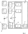
- a blocksheet representation 30 of the method and the controller according to an embodiment is presented in Figure 3 .
- the unique prime number label 31 identifies a functional unit 32.
- a multiplier 33 may be present which multiplies the product of the traversal value and the unique prime number label 31.
- a memory unit 34 may store the product of the traversal value and the unique prime number label.
- a plurality of functional units 35, 36 may be present.
- a fault comparator and unique prime factorisation unit 37 can determine if any functional units are faulty and if so, which units are faulty.
- the functional units may be connected in series.
- the functional units may also be connected in parallel.
- the functional units may also be connected in a combination of series and parallel.
- the functional units may be a subgroup selected from the functional units comprised in the vehicle control system.
- the functional unit subgroup may be associated with a specific function of the vehicle.
- the functional unit subgroup may in an embodiment be associated with multiple related functions of the vehicle.
- the expected traversal value of the functional unit subgroup is the product of the unique prime number label of each of the functional units comprised in the functional unit subgroup.
- a processing unit is responsible for the overall operation and control of the method.
- the processing unit may be implemented in any known controller technology, including but not limited to a processor (PLC, CPU, DSP), FPGA, ASIC or any other suitable digital and/or analogue circuitry capable of performing the intended functionality.
- PLC processor
- CPU central processing unit
- DSP digital signal processor
- FPGA field-programmable gate array
- ASIC application specific integrated circuit
- the system and controller may have a memory which is operatively connected to the processing unit.
- the memory may be implemented by any known memory technology, including but not limited to E(E)PROM, S(D)RAM and flash memory, and it may also include secondary storage such as a magnetic or optical disc. Physically, the memory may consist of one unit or a plurality of units which together constitute the memory on a logical level.
- the memory also comprises program instructions and work data for a control software application executed in the controller, system or processing unit.
- a vehicle control system comprises 4 functional units F 1-4 , the functional units are assigned the following unique prime labels according to the sequence of unique primes starting at the number 2.
- the first functional unit, F 1 is called with an initial traversal value of 1.
- the second functional unit in series, F 2 is then called with a traversal value of 2.
- the third functional unit, F 3 is then called with a traversal value of 6.
- the fourth functional unit, F 4 is then called with a traversal value of 30.
- the traversal value is then compared with the expected traversal value.
- the values are equal and hence no faults were detected in the system.
- a vehicle control system comprises 4 functional units F 1-4 , the functional units are assigned the following unique prime labels according to the sequence of unique primes starting at the number 2.
- the first functional unit, F 1 is called with an initial traversal value of 1.
- the first functional unit, F 1 is in error and does therefore not update the traversal value.
- the second functional unit, F 2 is then called with a traversal value of 1, the non-updated traversal value.
- the third functional unit, F 3 is then called with a traversal value of 3.
- the fourth functional unit, F 4 is then called with a traversal value of 15.
- the real traversal value is then compared with the expected traversal value.
- the values are not equal and thus fault is present in the vehicle's control system.
- the functional unit which was in error can be determined through a prime factorization algorithm as described above.
- the real traversal value is divided by the lowest prime factor.
- the lowest prime factor of 105 is 3. Accordingly 105 is divided by 3, resulting in a quotient of 35.
- the factor 3 is added to a set of real traversal value factors.
- the previous quotient 35 is then divided by the next lowest prime factor, 5, resulting in a quotient of 7.
- the factor 5 is added to the set of real traversal value factors.
- the previous quotient 7 is then divided by the next lowest prime factor, 7, resulting in a quotient of 1.
- the factor 7 is added to the set of real traversal value factors. As the previous quotient is 1, a prime number, the algorithm is stopped.
- the set of real traversal value factors is then compared to the expected set of unique prime labels.
- the missing factor is 2.
- the functional unit with the label 2 is faulty.
- the functional unit with the label 2 can thereafter be compared to a list associating functional units with subsystems and specific hardware components of the vehicle.
- the functional unit with the unique prime label 2 may be comprised within a subsystem relating to vehicle dynamics and associated with the brake actuation sensor.
- a vehicle control system comprises 4 functional units F 1-4 , the functional units are assigned the following unique prime labels according to the sequence of unique primes starting at the number 2.
- the first functional unit, F 1 is called with an initial traversal value of 1.
- the first functional unit, F 1 is in error and does therefore not update the traversal value.
- the second functional unit, F 2 is then called with a traversal value of 1, the non-updated traversal value.
- the third functional unit, F 3 is then called with a traversal value of 3.
- the third functional unit, F 3 is in error and does therefore not update the traversal value.
- the fourth functional unit, F 4 is then called with a traversal value of 3.
- the real traversal value is then compared with the expected traversal value.
- the real traversal value is 21. The values are not equal and thus fault is present in the vehicle's control system.
- the functional unit which was in error can be determined through a prime factorization algorithm as described above.
- the real traversal value is divided by the lowest prime factor.
- the lowest prime factor of 21 is 3. Accordingly 21 is divided by 3, resulting in a quotient of 7.
- the factor 3 is added to a set of real traversal value factors. As the previous quotient is 7, a prime number, the algorithm is stopped.
- the set of real traversal value factors is then compared to the expected set of unique prime labels.
- the functional unit with the labels 2 and 5 can thereafter be compared to a list associating functional units with subsystems and specific hardware components of the vehicle as above.
Landscapes
- Engineering & Computer Science (AREA)
- Automation & Control Theory (AREA)
- Mechanical Engineering (AREA)
- Transportation (AREA)
- Human Computer Interaction (AREA)
- Physics & Mathematics (AREA)
- General Physics & Mathematics (AREA)
- General Engineering & Computer Science (AREA)
- Theoretical Computer Science (AREA)
- Combustion & Propulsion (AREA)
- Chemical & Material Sciences (AREA)
- Computer Hardware Design (AREA)
- Quality & Reliability (AREA)
- Testing And Monitoring For Control Systems (AREA)
- Debugging And Monitoring (AREA)
Description
- The invention relates to vehicle control systems, in particular methods and systems for detecting faults in vehicle control systems.
- Modern vehicle control systems are comprised of a network of systems, subsystems and controllers interacting to control the various components of the vehicle. For example a vehicle control system could comprise subsystems associated with a domain of features of the vehicle such as vehicle dynamics. Each of these subsystems may comprise one or more electronic control units (ECUs) which are associated with a feature of the domain, for example the vehicle dynamics subsystem may comprise an ECU relating to braking. The subsystems also comprise functional units that are related to that domain subsystem. A functional unit could for example be a brake actuation sensor. The functional units are often interconnected which makes detecting and locating faults rapidly a challenge.
- With such vehicle control systems comprising numerous subsystems communicating and controlling various aspects of the vehicle, testing and validation of large electronic control systems is of significant importance. Furthermore, the increasing numbers of features in vehicle control systems has in turn increased the proportion of vehicle production costs associated with control systems. A fault detection method and system for vehicle control system being able to detect faults efficiently and effectively during production and development would thus decrease production costs and increase vehicle reliability.
- Examples of prior art are reflected in the
US-application US2012185126 disclosing a vehicle control system diagnostic tool and theUS-application US2006047480 disclosing a method of diagnosing a temperature sensing system. - The present invention is defined by the appended independent claims.
- Accordingly, the present invention preferably seeks to mitigate or eliminate one or more of the above-identified deficiencies in the art singly or in any combination and solves at least the above mentioned problems by providing a solution in accordance with the independent claims set forth below.
- According to a first aspect, a method for detecting faults in a vehicle control system comprising functional units having an associated unique prime number label is provided. The method comprises calling each of the functional units, the call comprising a readable and updateable integer traversal value, and in case the functional unit is operating correctly, updating the traversal value to be the product of the value in the call and the label of the currently called functional unit, and in the case of a fault, not updating the traversal value; and determining from the traversal value if any functional units are faulty by a comparison with an expected traversal value, and, in the case that the traversal value is not equivalent to the expected traversal value, determining which functional units are faulty by a unique prime factorization algorithm.
- In an embodiment, the vehicle control system comprises two or more functional units.
- The unique prime label may be associated according to the ascending sequence of prime numbers starting at the
number 2. - In an embodiment, faulty units are detected by comparing the traversal value with an expected traversal value, if the stored value is not equal to the expected value then the missing prime factor(s) are determined through a unique prime factorization algorithm.
- The method may further comprise accessing a list, the list associating a descriptor of a functional unit to a unique prime number label, to determine the descriptor of any faulty functional units.
- In an embodiment, the vehicle control system further comprises subsystems being associated with vehicle hardware, wherein the subsystems comprise the functional units, the method further comprising associating the functional units with the comprising subsystem.
- In an embodiment a functional unit subset may be selected from the functional units comprised in the vehicle control system, such that only a subset of related or associated functional units are tested.
- According to a second aspect a controller for detecting faults in a vehicle control system comprising functional units is provided. Each of the functional units of the vehicle control system are assigned a unique prime number from the ascending sequence of prime numbers starting at 2. The controller for detecting faults comprises a means of calling the functional units wherein the call to the functional unit comprises, a readable and updateable integer traversal value, a means of, in case the functional unit is operating correctly, updating the traversal value to be the product of the value in the call and the label of the currently called functional unit, and in the case of a fault, not updating the traversal value; and a processing unit programmed to determine which if any of the functional units are faulty by a unique prime factorization algorithm.
- In an embodiment the processing unit is programmed to detect any faulty functional units by comparing the product stored in the detection signal with an expected traversal value, if the stored value is not equal to the expected traversal value then the missing prime factor(s) are determined through a unique prime factorization algorithm.
- According to a third aspect a method for providing at least one implemented unit is provided. The method comprises assigning a unique prime label to a functional unit, and wherein the unique prime label is assigned from the ascending sequence of prime numbers starting at the
number 2. - According to a fourth aspect a system is provided comprising a hardware component of a vehicle being associated with one or more functional units and a controller according to the third aspect.
- Further objects, features and advantages will appear from the following detailed description, with reference being made to the accompanying drawings, in which:
-
Fig. 1 is a schematic view of a method according to an embodiment; -
Fig. 2 is a schematic view of a method according to another embodiment; -
Fig. 3 is a blocksheet diagram of the method according to an embodiment; -
Fig. 4 is a blocksheet diagram of the method according to example 1; -
Fig. 5 is a blocksheet diagram of the method according to example 2; and -
Fig. 6 is a blocksheet diagram of the method according to example 3. - The following description of the invention concerns methods, controllers and systems for detecting faults in vehicle control systems comprising functional units having an associated unique prime number label. The functional units may be associated with specific components of a vehicle. For instance, the functional units may be associated with those directly related to the movement of the vehicle, such as a break actuation sensor. The functional units may also be associated with components related to ancillary aspects of the vehicle such as a seat warming controller. Through the described methods, controllers and systems faults in one or more individual functional units can be detected and located efficiently and effectively. The vehicles control system can comprise one or more functional units, such as two or more. Functional units may be software implemented.
- Functional units are assigned a unique prime number label to enable identification.
Such method 20 is generally depicted inFig. 2 . The unique prime number label can be assigned 24 to the functional unit during or prior to run-time, and preferably after accessing thefunctional unit 22. The unique prime number label acts as an identifier of the functional unit throughout the fault detection method. An ideal method of assigning the unique prime number labels is to assign labels from the ascending sequence of prime numbers starting from theprime number 2. That is, the unique prime number label of the first functional unit is assigned thenumber 2, the unique prime number label of the second functional unit is assigned thenumber 3, the unique prime number label of the thirdfunctional unit 5 and so on. Theprime number 1 is preferably not used as a unique prime number label of a functional unit. - Each functional unit can be called during the fault detection method. The
fault detection method 10 is schematically shown inFig. 1 . Thecall 12 to the functional unit comprises a traversal value. The traversal value is an integer value which can be both read and updated by the respective receiving functional unit. The traversal value which is provided 14 to the first functional unit during fault detection is thevalue 1. - On receiving the call, in the case that the receiving functional unit is operating correctly, the receiving functional unit can update 16 the traversal value to be equal to the product of the traversal value comprised in the call and the unique prime label of the currently called functional unit. The multiplication results in an integer product which is the product of the receiving functional unit's unique prime label and the product of all functional units previously called that were without error. The traversal value is then updated to be equal to the product.
- A faulty functional unit which is an error state will not update the traversal value. The traversal value will thus be unchanged by a functional unit which is faulty.
- The traversal value is then passed in a call to the next functional unit. The next functional unit repeats the multiplication process described above with its own unique prime number label.
- To determine if any of the functional units are faulty the traversal value can be compared to an expected traversal value. To determine 18 which functional units are in error a unique prime factorisation algorithm is used.
- After being passed to one or more functional units the traversal value is compared to an expected traversal value. The expected traversal value may be the product of all of the unique prime number labels of functional units in the system in which faults are to be detected. For example, if the system comprised functional units with unique prime number labels 2, 3, 5, 7 then the expected value would be 2x3x5x7 = 210.
- If the traversal value is equal to the expected traversal value then no faults have been detected in the system.
- If the traversal value is not equal to the expected traversal value then one or more faulty functional units have been detected.
- To determine which functional unit is faulty a unique prime factorisation algorithm is used.
- One unique prime factorisation algorithm is described hereafter. The traversal value is first divided by the lowest prime factor of the traversal value. If the quotient is not a prime number then the quotient is subsequently divided by the next lowest prime. This process is repeated for the subsequent prime factors until the quotient is a prime number.
- If, at any point, the quotient is a prime number then the process is stopped and the set of prime divisors is compared to the expected set of unique prime labels. The unique prime labels which are missing from the set of prime divisors are the unique prime labels of functional units which are faulty.
- With this method it is possible to detect a fault in a single functional unit as described in Example 2. It is also possible to detect faults in multiple functional units. Detecting faults in multiple functional units is described in Example 3.
- The vehicle control system may also comprise subsystems being associated with vehicle hardware. In such a case the subsystems comprise the functional units. For example, a drivetrain subsystem could comprise multiple functional units associated with of the combined pieces of hardware associated with the vehicle's drivetrain.
- If the functional units are comprised in subsystems then the method of detecting faults may further comprise associating the functional units with the comprising subsystem.
- The method of detecting faults in a vehicle control system may also comprise a step for determining which hardware component is associated with a functional unit. The method can comprise accessing a list associating a hardware descriptor to a functional unit. The list may comprise a sequence of unique prime number labels, being the unique prime number labels of the function units. The list may also comprise a text based or other descriptor of which vehicular hardware component is related to each unique prime number label. The descriptor could be any machine or human readable descriptor or ID of a vehicular hardware component.
- Also disclosed herein is a controller for detecting faults in a vehicle control system comprising functional units. For identification each of the functional units of the vehicle control system can be assigned a unique prime number label from the ascending sequence of prime numbers starting at 2.
- The controller for detecting faults further comprises a means of calling the functional units wherein the call to the functional unit comprises, a readable and updateable traversal value for enabling identification of which functional units are faulty. The controller comprises a means of, in case the functional unit is operating correctly, updating the traversal value to be the product of the traversal value comprised in the call and the unique prime label of the currently called functional unit, and in the case of a fault, not updating the traversal value.
- The controller further detects whether the functional units are faulty as it is provided with means of comparing the traversal value with an expected traversal value, and a means of determining which functional units are faulty. In case the traversal value is equal to the expected traversal value then no faults have been detected in the vehicle control system. In the case that the traversal value is not equal to the expected traversal value the controller one or more faults are present in the vehicle control system. The controller can determine which functional units are faulty by a unique prime factorisation algorithm.
- A vehicle may comprise a system comprising at least one hardware component of a vehicle associated with one or more functional units and a controller according to the description above. For example a system could comprise a hardware component such as a brake actuation sensor, a controller as described above, and at least one functional unit. The system may further comprise a list associating a hardware component descriptor to a functional unit.
- A
blocksheet representation 30 of the method and the controller according to an embodiment is presented inFigure 3 . The uniqueprime number label 31 identifies afunctional unit 32. Amultiplier 33 may be present which multiplies the product of the traversal value and the uniqueprime number label 31. Amemory unit 34 may store the product of the traversal value and the unique prime number label. A plurality offunctional units prime factorisation unit 37 can determine if any functional units are faulty and if so, which units are faulty. - The functional units may be connected in series. The functional units may also be connected in parallel. The functional units may also be connected in a combination of series and parallel.
- In an embodiment the functional units may be a subgroup selected from the functional units comprised in the vehicle control system. In such an embodiment the functional unit subgroup may be associated with a specific function of the vehicle. The functional unit subgroup may in an embodiment be associated with multiple related functions of the vehicle. The expected traversal value of the functional unit subgroup is the product of the unique prime number label of each of the functional units comprised in the functional unit subgroup.
- A processing unit is responsible for the overall operation and control of the method. The processing unit may be implemented in any known controller technology, including but not limited to a processor (PLC, CPU, DSP), FPGA, ASIC or any other suitable digital and/or analogue circuitry capable of performing the intended functionality. The processing unit constitutes an implementation of the method described herein.
- Finally, the system and controller may have a memory which is operatively connected to the processing unit. The memory may be implemented by any known memory technology, including but not limited to E(E)PROM, S(D)RAM and flash memory, and it may also include secondary storage such as a magnetic or optical disc. Physically, the memory may consist of one unit or a plurality of units which together constitute the memory on a logical level. In addition to storing various program instructions and data for the various functions and applications which are typically available, the memory also comprises program instructions and work data for a control software application executed in the controller, system or processing unit.
- A vehicle control system comprises 4 functional units F1-4, the functional units are assigned the following unique prime labels according to the sequence of unique primes starting at the
number 2.Functional Unit Unique prime label F1 2 F2 3 F3 5 F 47 - The first functional unit, F1 , is called with an initial traversal value of 1. The first functional unit, F1 , is not in error and updates the traversal value to be equal to 1 x 2 = 2. The second functional unit in series, F2 , is then called with a traversal value of 2. The second functional unit, F2 , is not in error and updates the traversal value to be equal to 2 x 3 = 6. The third functional unit, F3 , is then called with a traversal value of 6. The third functional unit, F3 , is not in error and updates the traversal value to be equal to 6 x 5 = 30. The fourth functional unit, F4 , is then called with a traversal value of 30. The fourth functional unit, F4 , is not in error and updates the traversal value to be equal to 30 x 7 = 210.
- The traversal value is then compared with the expected traversal value. In this case the expected traversal value is 2 x 3 x 5 x 7 = 210. The values are equal and hence no faults were detected in the system.
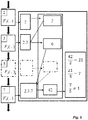
- This example is presented as a blocksheet in
Figure 4 . - A vehicle control system comprises 4 functional units F1-4, the functional units are assigned the following unique prime labels according to the sequence of unique primes starting at the
number 2.Functional Unit Unique prime label F1 2 F2 3 F3 5 F 47 - The first functional unit, F1 , is called with an initial traversal value of 1. The first functional unit, F1 , is in error and does therefore not update the traversal value. The second functional unit, F2 , is then called with a traversal value of 1, the non-updated traversal value. The second functional unit, F2 , is not in error and updates the traversal value to be equal to 1 x 3 = 3. The third functional unit, F3 , is then called with a traversal value of 3. The third functional unit, F3 , is not in error and updates the traversal value to be equal to 3 x 5 = 15. The fourth functional unit, F4 , is then called with a traversal value of 15. The fourth functional unit, F4 , is not in error and updates the traversal value to be equal to 15 x 7 = 105.
- The real traversal value is then compared with the expected traversal value. In this case the expected traversal value is 2 x 3 x 5 x 7 = 210. The values are not equal and thus fault is present in the vehicle's control system.
- The functional unit which was in error can be determined through a prime factorization algorithm as described above.
- The real traversal value is divided by the lowest prime factor. The lowest prime factor of 105 is 3. Accordingly 105 is divided by 3, resulting in a quotient of 35. The
factor 3 is added to a set of real traversal value factors. Theprevious quotient 35 is then divided by the next lowest prime factor, 5, resulting in a quotient of 7. Thefactor 5 is added to the set of real traversal value factors. Theprevious quotient 7 is then divided by the next lowest prime factor, 7, resulting in a quotient of 1. Thefactor 7 is added to the set of real traversal value factors. As the previous quotient is 1, a prime number, the algorithm is stopped. - The set of real traversal value factors is then compared to the expected set of unique prime labels.
- Real traversal value factors = {3,5,7}
- Expected set of unique prime labels = {2,3,5,7}
- In this example, the missing factor is 2. Thus the functional unit with the
label 2 is faulty. - The functional unit with the
label 2 can thereafter be compared to a list associating functional units with subsystems and specific hardware components of the vehicle. For instance, the functional unit with the uniqueprime label 2 may be comprised within a subsystem relating to vehicle dynamics and associated with the brake actuation sensor. - This example is presented as a blocksheet in
Figure 5 . - A vehicle control system comprises 4 functional units F1-4, the functional units are assigned the following unique prime labels according to the sequence of unique primes starting at the
number 2.Functional Unit Unique prime label F1 2 F2 3 F3 5 F 47 - The first functional unit, F1 , is called with an initial traversal value of 1. The first functional unit, F1 , is in error and does therefore not update the traversal value. The second functional unit, F2 , is then called with a traversal value of 1, the non-updated traversal value. The second functional unit, F2 , is not in error and updates the traversal value to be equal to 1 x 3 = 3. The third functional unit, F3 , is then called with a traversal value of 3. The third functional unit, F3 , is in error and does therefore not update the traversal value. The fourth functional unit, F4 , is then called with a traversal value of 3. The fourth functional unit, F4 , is not in error and updates the traversal value to be equal to 3 x 7 = 21.
- The real traversal value is then compared with the expected traversal value. In this case the expected traversal value is 2 x 3 x 5 x 7 = 210. The real traversal value is 21. The values are not equal and thus fault is present in the vehicle's control system.
- The functional unit which was in error can be determined through a prime factorization algorithm as described above.
- The real traversal value is divided by the lowest prime factor. The lowest prime factor of 21 is 3. Accordingly 21 is divided by 3, resulting in a quotient of 7. The
factor 3 is added to a set of real traversal value factors. As the previous quotient is 7, a prime number, the algorithm is stopped. - The set of real traversal value factors is then compared to the expected set of unique prime labels.
- Real traversal value factors = {3,7}
- Expected set of unique prime labels = {2,3,5,7}
- In this example, there are two missing factors, 2 and 5. Thus the functional units with the
labels - The functional unit with the
labels - This example is presented as a blocksheet in
Figure 6 .
Claims (10)
- A method (10) for detecting faults in a vehicle control system comprising functional units (32, 35, 36) having an associated unique prime number label (31), the method comprising:calling (12) each of the functional units (32, 35, 36), the call comprising a readable and updateable integer traversal value, and in case the functional unit (32, 35, 36) is operating correctly, updating (16) the traversal value to be the product of the value in the call and the label (31) of the currently called functional unit (32, 35, 36), and in the case of a fault, not updating the traversal value;determining (18) from the traversal value if any functional units (32, 35, 36) are faulty by a comparison with an expected traversal value, and, in the case that the traversal value is not equivalent to the expected traversal value, determining which functional units (32, 35, 36) are faulty by a unique prime factorization algorithm.
- The method according to claim 1 wherein the vehicle control system comprises two or more functional units (32, 35, 36).
- The method according to claim 1 or 2 wherein the unique prime label (31) is associated according to the ascending sequence of prime numbers starting at the number 2.
- The method according to any of the preceding claims wherein faulty units are detected by comparing the traversal value with an expected traversal value, if the stored value is not equal to the expected value then the missing prime factor(s) are determined through a unique prime factorization algorithm.
- The method according to any of the proceeding claims wherein the method further comprises accessing (22) a list, the list associating a descriptor of a functional unit (32, 35, 36) to a unique prime number label (31), to determine the descriptor of any faulty functional units (32, 35, 36).
- The method according to any of the proceeding claims wherein the vehicle control system further comprises subsystems being associated with vehicle hardware, wherein the subsystems comprise the functional units (32, 35, 36), the method further comprising associating the functional units (32, 35, 36) with the comprising subsystem.
- The method according to any of the preceding claims wherein a functional unit (32, 35, 36) subset is selected from the functional units (32, 35, 36) comprised in the vehicle control system, and wherein the expected traversal value of the functional unit (32, 35, 36) subset is the product of the unique prime number label (31) of each of the functional units (32, 35, 36) comprised in the functional unit subset.
- A controller for detecting faults in a vehicle control system comprising functional units (32, 35, 36), wherein each of the functional units (32, 35, 36) of the vehicle control system are assigned (24) a unique prime number from the ascending sequence of prime numbers starting at 2;
the controller for detecting faults comprising:a means of calling (12) the functional units (32, 35, 36) wherein the call to the functional unit comprises, a readable and updateable integer traversal value,a means of, in case the functional unit (32, 35, 36) is operating correctly, updating the traversal value to be the product of the value in the call and the label (31) of the currently called functional unit (32, 35, 36), and in the case of a fault, not updating the traversal value;a processing unit programmed to determine which if any of the functional units (32, 35, 36) are faulty by a unique prime factorization algorithm. - The controller according to claim 7 wherein the processing unit is programmed to detect any faulty functional units (32, 35, 36) by comparing the traversal value stored in the detection signal with an expected traversal value, if the stored traversal value is not equal to the expected traversal value then the missing prime factor(s) are determined through a unique prime factorization algorithm.
- 10. A system comprising a hardware component of a vehicle being associated with one or more functional units (32, 35, 36) and a controller according to claim 7 to 8.
Applications Claiming Priority (2)
| Application Number | Priority Date | Filing Date | Title |
|---|---|---|---|
| SE1550231A SE541032C2 (en) | 2015-02-27 | 2015-02-27 | Methods and systems for detecting faults in vehicle control systems |
| PCT/EP2016/054071 WO2016135282A1 (en) | 2015-02-27 | 2016-02-26 | Methods and systems for detecting faults in vehicle control systems |
Publications (2)
| Publication Number | Publication Date |
|---|---|
| EP3261891A1 EP3261891A1 (en) | 2018-01-03 |
| EP3261891B1 true EP3261891B1 (en) | 2020-04-29 |
Family
ID=55453144
Family Applications (1)
| Application Number | Title | Priority Date | Filing Date |
|---|---|---|---|
| EP16707695.9A Active EP3261891B1 (en) | 2015-02-27 | 2016-02-26 | Method and apparatuses for detecting faults in vehicle control systems |
Country Status (5)
| Country | Link |
|---|---|
| US (1) | US9830752B2 (en) |
| EP (1) | EP3261891B1 (en) |
| CN (1) | CN106660545B (en) |
| SE (1) | SE541032C2 (en) |
| WO (1) | WO2016135282A1 (en) |
Families Citing this family (1)
| Publication number | Priority date | Publication date | Assignee | Title |
|---|---|---|---|---|
| CN111497868A (en) * | 2020-04-09 | 2020-08-07 | 余姚市浙江大学机器人研究中心 | A fault classification method for automobile sensors based on BN-LSTM network |
Citations (3)
| Publication number | Priority date | Publication date | Assignee | Title |
|---|---|---|---|---|
| US20060047480A1 (en) * | 2004-08-31 | 2006-03-02 | Watlow Electric Manufacturing Company | Method of temperature sensing |
| US20080033987A1 (en) * | 2006-08-02 | 2008-02-07 | Carter Joe K | Primenet data management system |
| US20120185126A1 (en) * | 2011-01-19 | 2012-07-19 | GM Global Technology Operations LLC | Vehicle control system diagnostic tool |
Family Cites Families (7)
| Publication number | Priority date | Publication date | Assignee | Title |
|---|---|---|---|---|
| JPH06160245A (en) | 1992-11-24 | 1994-06-07 | Toyota Motor Corp | Abnormality diagnosis system for vehicle |
| US6341247B1 (en) * | 1999-12-17 | 2002-01-22 | Mcdonell Douglas Corporation | Adaptive method to control and optimize aircraft performance |
| DE10244131B4 (en) * | 2002-09-23 | 2006-11-30 | Siemens Ag | Method for supporting identification of a defective functional unit in a technical installation |
| KR100948581B1 (en) | 2008-04-11 | 2010-03-18 | 한국과학기술원 | Data storage method in supply chain management using RDF, query processing method for stored data, and supply chain data management system using RDF |
| US20100157051A1 (en) * | 2008-12-23 | 2010-06-24 | International Business Machines Corporation | System and method for detecting and deterring rfid tag related fraud |
| US20130006697A1 (en) | 2011-06-29 | 2013-01-03 | International Business Machines Corporation | Using prime numbers and prime number factorization to track articles through transit points in a supply chain |
| CN103430223B (en) | 2011-09-21 | 2016-07-06 | 株式会社Lg化学 | Water immersion detection circuit and water immersion detection device using the water immersion detection circuit |
-
2015
- 2015-02-27 SE SE1550231A patent/SE541032C2/en unknown
-
2016
- 2016-02-26 CN CN201680001653.9A patent/CN106660545B/en active Active
- 2016-02-26 WO PCT/EP2016/054071 patent/WO2016135282A1/en not_active Ceased
- 2016-02-26 EP EP16707695.9A patent/EP3261891B1/en active Active
- 2016-08-29 US US15/250,566 patent/US9830752B2/en active Active
Patent Citations (3)
| Publication number | Priority date | Publication date | Assignee | Title |
|---|---|---|---|---|
| US20060047480A1 (en) * | 2004-08-31 | 2006-03-02 | Watlow Electric Manufacturing Company | Method of temperature sensing |
| US20080033987A1 (en) * | 2006-08-02 | 2008-02-07 | Carter Joe K | Primenet data management system |
| US20120185126A1 (en) * | 2011-01-19 | 2012-07-19 | GM Global Technology Operations LLC | Vehicle control system diagnostic tool |
Non-Patent Citations (1)
| Title |
|---|
| VIJAIYA PRATHAP ET AL: "Penetration Testing of Vehicle ECUs Master of Science Thesis in the program networks and Distributed systems", 1 January 2013 (2013-01-01), XP055639294, Retrieved from the Internet <URL:http://publications.lib.chalmers.se/records/fulltext/184988/184988.pdf> [retrieved on 20191105] * |
Also Published As
| Publication number | Publication date |
|---|---|
| WO2016135282A1 (en) | 2016-09-01 |
| US9830752B2 (en) | 2017-11-28 |
| SE541032C2 (en) | 2019-03-12 |
| CN106660545A (en) | 2017-05-10 |
| SE1550231A1 (en) | 2016-08-28 |
| CN106660545B (en) | 2019-12-20 |
| US20160364923A1 (en) | 2016-12-15 |
| EP3261891A1 (en) | 2018-01-03 |
Similar Documents
| Publication | Publication Date | Title |
|---|---|---|
| CN107918382B (en) | Automobile fault diagnosis method, automobile fault diagnosis device and electronic equipment | |
| US10394675B2 (en) | Vehicle control device | |
| JP5518810B2 (en) | Vehicle control device and vehicle control system | |
| US11281441B2 (en) | Method and apparatus for compiling source code object, and computer | |
| US20040254696A1 (en) | Fault diagnostic method and device | |
| CN104965696B (en) | For influenceing the method and modeling of control program | |
| US9830752B2 (en) | Methods and systems for detecting faults in vehicle control systems | |
| CN114371683A (en) | Diagnostic function verification method, system, storage medium and device of diagnostic instrument | |
| Kriebel et al. | The next generation of bmw’s electrified powertrains: Providing software features quickly by model-based system design | |
| CN112445802B (en) | Database capacity expansion method, device, electronic equipment and computer storage medium | |
| CN110161835B (en) | Method and apparatus for computing a data model in a safety-critical system | |
| CN116155965B (en) | Multi-stage control method of omnidirectional AMR | |
| CN106909599A (en) | A kind of group system, message treatment method and device | |
| KR20240163235A (en) | Data processing apparatus and method for constructing learning model | |
| WO2018037117A1 (en) | Methods and systems for detecting faults in vehicle control systems | |
| JP2016189118A (en) | Electronic control apparatus | |
| JP6921219B2 (en) | Distributed control system | |
| CN119718951B (en) | A software testing method, server, rack, and computer program product | |
| CN114021299B (en) | Method, device, computer equipment and storage medium for detecting an object | |
| CN115934402B (en) | A method, apparatus, and server for preserving fault scene | |
| CN114612022B (en) | Implementation method, device, equipment and storage medium for ultrapure water treatment monitoring | |
| CN117331350A (en) | Apparatus and methods for controlling process facilities and process control systems | |
| US12325437B2 (en) | Method for synchronizing a clock-free computational node in a vehicle, method for performing an action at a pre-defined time, first computational node, second computational node and computational system for a vehicle | |
| US20240202108A1 (en) | Computer-implemented method for determining compatible system elements and system | |
| EP4401016A1 (en) | Method for generating and training a system model, selecting a controller, system, computer-system |
Legal Events
| Date | Code | Title | Description |
|---|---|---|---|
| STAA | Information on the status of an ep patent application or granted ep patent |
Free format text: STATUS: THE INTERNATIONAL PUBLICATION HAS BEEN MADE |
|
| PUAI | Public reference made under article 153(3) epc to a published international application that has entered the european phase |
Free format text: ORIGINAL CODE: 0009012 |
|
| STAA | Information on the status of an ep patent application or granted ep patent |
Free format text: STATUS: REQUEST FOR EXAMINATION WAS MADE |
|
| 17P | Request for examination filed |
Effective date: 20161208 |
|
| AK | Designated contracting states |
Kind code of ref document: A1 Designated state(s): AL AT BE BG CH CY CZ DE DK EE ES FI FR GB GR HR HU IE IS IT LI LT LU LV MC MK MT NL NO PL PT RO RS SE SI SK SM TR |
|
| AX | Request for extension of the european patent |
Extension state: BA ME |
|
| DAV | Request for validation of the european patent (deleted) | ||
| DAX | Request for extension of the european patent (deleted) | ||
| STAA | Information on the status of an ep patent application or granted ep patent |
Free format text: STATUS: EXAMINATION IS IN PROGRESS |
|
| 17Q | First examination report despatched |
Effective date: 20190531 |
|
| GRAP | Despatch of communication of intention to grant a patent |
Free format text: ORIGINAL CODE: EPIDOSNIGR1 |
|
| STAA | Information on the status of an ep patent application or granted ep patent |
Free format text: STATUS: GRANT OF PATENT IS INTENDED |
|
| RIC1 | Information provided on ipc code assigned before grant |
Ipc: B60W 50/02 20120101AFI20191114BHEP Ipc: B60W 50/04 20060101ALI20191114BHEP |
|
| INTG | Intention to grant announced |
Effective date: 20191209 |
|
| GRAS | Grant fee paid |
Free format text: ORIGINAL CODE: EPIDOSNIGR3 |
|
| GRAA | (expected) grant |
Free format text: ORIGINAL CODE: 0009210 |
|
| STAA | Information on the status of an ep patent application or granted ep patent |
Free format text: STATUS: THE PATENT HAS BEEN GRANTED |
|
| AK | Designated contracting states |
Kind code of ref document: B1 Designated state(s): AL AT BE BG CH CY CZ DE DK EE ES FI FR GB GR HR HU IE IS IT LI LT LU LV MC MK MT NL NO PL PT RO RS SE SI SK SM TR |
|
| REG | Reference to a national code |
Ref country code: GB Ref legal event code: FG4D |
|
| REG | Reference to a national code |
Ref country code: CH Ref legal event code: EP |
|
| REG | Reference to a national code |
Ref country code: AT Ref legal event code: REF Ref document number: 1262862 Country of ref document: AT Kind code of ref document: T Effective date: 20200515 |
|
| REG | Reference to a national code |
Ref country code: DE Ref legal event code: R096 Ref document number: 602016035020 Country of ref document: DE |
|
| REG | Reference to a national code |
Ref country code: IE Ref legal event code: FG4D |
|
| REG | Reference to a national code |
Ref country code: NL Ref legal event code: MP Effective date: 20200429 |
|
| REG | Reference to a national code |
Ref country code: LT Ref legal event code: MG4D |
|
| PG25 | Lapsed in a contracting state [announced via postgrant information from national office to epo] |
Ref country code: LT Free format text: LAPSE BECAUSE OF FAILURE TO SUBMIT A TRANSLATION OF THE DESCRIPTION OR TO PAY THE FEE WITHIN THE PRESCRIBED TIME-LIMIT Effective date: 20200429 Ref country code: PT Free format text: LAPSE BECAUSE OF FAILURE TO SUBMIT A TRANSLATION OF THE DESCRIPTION OR TO PAY THE FEE WITHIN THE PRESCRIBED TIME-LIMIT Effective date: 20200831 Ref country code: GR Free format text: LAPSE BECAUSE OF FAILURE TO SUBMIT A TRANSLATION OF THE DESCRIPTION OR TO PAY THE FEE WITHIN THE PRESCRIBED TIME-LIMIT Effective date: 20200730 Ref country code: FI Free format text: LAPSE BECAUSE OF FAILURE TO SUBMIT A TRANSLATION OF THE DESCRIPTION OR TO PAY THE FEE WITHIN THE PRESCRIBED TIME-LIMIT Effective date: 20200429 Ref country code: SE Free format text: LAPSE BECAUSE OF FAILURE TO SUBMIT A TRANSLATION OF THE DESCRIPTION OR TO PAY THE FEE WITHIN THE PRESCRIBED TIME-LIMIT Effective date: 20200429 Ref country code: IS Free format text: LAPSE BECAUSE OF FAILURE TO SUBMIT A TRANSLATION OF THE DESCRIPTION OR TO PAY THE FEE WITHIN THE PRESCRIBED TIME-LIMIT Effective date: 20200829 Ref country code: NO Free format text: LAPSE BECAUSE OF FAILURE TO SUBMIT A TRANSLATION OF THE DESCRIPTION OR TO PAY THE FEE WITHIN THE PRESCRIBED TIME-LIMIT Effective date: 20200729 |
|
| REG | Reference to a national code |
Ref country code: AT Ref legal event code: MK05 Ref document number: 1262862 Country of ref document: AT Kind code of ref document: T Effective date: 20200429 |
|
| PG25 | Lapsed in a contracting state [announced via postgrant information from national office to epo] |
Ref country code: BG Free format text: LAPSE BECAUSE OF FAILURE TO SUBMIT A TRANSLATION OF THE DESCRIPTION OR TO PAY THE FEE WITHIN THE PRESCRIBED TIME-LIMIT Effective date: 20200729 Ref country code: LV Free format text: LAPSE BECAUSE OF FAILURE TO SUBMIT A TRANSLATION OF THE DESCRIPTION OR TO PAY THE FEE WITHIN THE PRESCRIBED TIME-LIMIT Effective date: 20200429 Ref country code: HR Free format text: LAPSE BECAUSE OF FAILURE TO SUBMIT A TRANSLATION OF THE DESCRIPTION OR TO PAY THE FEE WITHIN THE PRESCRIBED TIME-LIMIT Effective date: 20200429 Ref country code: RS Free format text: LAPSE BECAUSE OF FAILURE TO SUBMIT A TRANSLATION OF THE DESCRIPTION OR TO PAY THE FEE WITHIN THE PRESCRIBED TIME-LIMIT Effective date: 20200429 |
|
| PG25 | Lapsed in a contracting state [announced via postgrant information from national office to epo] |
Ref country code: AL Free format text: LAPSE BECAUSE OF FAILURE TO SUBMIT A TRANSLATION OF THE DESCRIPTION OR TO PAY THE FEE WITHIN THE PRESCRIBED TIME-LIMIT Effective date: 20200429 Ref country code: NL Free format text: LAPSE BECAUSE OF FAILURE TO SUBMIT A TRANSLATION OF THE DESCRIPTION OR TO PAY THE FEE WITHIN THE PRESCRIBED TIME-LIMIT Effective date: 20200429 |
|
| PG25 | Lapsed in a contracting state [announced via postgrant information from national office to epo] |
Ref country code: ES Free format text: LAPSE BECAUSE OF FAILURE TO SUBMIT A TRANSLATION OF THE DESCRIPTION OR TO PAY THE FEE WITHIN THE PRESCRIBED TIME-LIMIT Effective date: 20200429 Ref country code: RO Free format text: LAPSE BECAUSE OF FAILURE TO SUBMIT A TRANSLATION OF THE DESCRIPTION OR TO PAY THE FEE WITHIN THE PRESCRIBED TIME-LIMIT Effective date: 20200429 Ref country code: EE Free format text: LAPSE BECAUSE OF FAILURE TO SUBMIT A TRANSLATION OF THE DESCRIPTION OR TO PAY THE FEE WITHIN THE PRESCRIBED TIME-LIMIT Effective date: 20200429 Ref country code: SM Free format text: LAPSE BECAUSE OF FAILURE TO SUBMIT A TRANSLATION OF THE DESCRIPTION OR TO PAY THE FEE WITHIN THE PRESCRIBED TIME-LIMIT Effective date: 20200429 Ref country code: DK Free format text: LAPSE BECAUSE OF FAILURE TO SUBMIT A TRANSLATION OF THE DESCRIPTION OR TO PAY THE FEE WITHIN THE PRESCRIBED TIME-LIMIT Effective date: 20200429 Ref country code: AT Free format text: LAPSE BECAUSE OF FAILURE TO SUBMIT A TRANSLATION OF THE DESCRIPTION OR TO PAY THE FEE WITHIN THE PRESCRIBED TIME-LIMIT Effective date: 20200429 Ref country code: IT Free format text: LAPSE BECAUSE OF FAILURE TO SUBMIT A TRANSLATION OF THE DESCRIPTION OR TO PAY THE FEE WITHIN THE PRESCRIBED TIME-LIMIT Effective date: 20200429 Ref country code: CZ Free format text: LAPSE BECAUSE OF FAILURE TO SUBMIT A TRANSLATION OF THE DESCRIPTION OR TO PAY THE FEE WITHIN THE PRESCRIBED TIME-LIMIT Effective date: 20200429 |
|
| REG | Reference to a national code |
Ref country code: DE Ref legal event code: R097 Ref document number: 602016035020 Country of ref document: DE |
|
| PG25 | Lapsed in a contracting state [announced via postgrant information from national office to epo] |
Ref country code: PL Free format text: LAPSE BECAUSE OF FAILURE TO SUBMIT A TRANSLATION OF THE DESCRIPTION OR TO PAY THE FEE WITHIN THE PRESCRIBED TIME-LIMIT Effective date: 20200429 Ref country code: SK Free format text: LAPSE BECAUSE OF FAILURE TO SUBMIT A TRANSLATION OF THE DESCRIPTION OR TO PAY THE FEE WITHIN THE PRESCRIBED TIME-LIMIT Effective date: 20200429 |
|
| PLBE | No opposition filed within time limit |
Free format text: ORIGINAL CODE: 0009261 |
|
| STAA | Information on the status of an ep patent application or granted ep patent |
Free format text: STATUS: NO OPPOSITION FILED WITHIN TIME LIMIT |
|
| 26N | No opposition filed |
Effective date: 20210201 |
|
| PG25 | Lapsed in a contracting state [announced via postgrant information from national office to epo] |
Ref country code: SI Free format text: LAPSE BECAUSE OF FAILURE TO SUBMIT A TRANSLATION OF THE DESCRIPTION OR TO PAY THE FEE WITHIN THE PRESCRIBED TIME-LIMIT Effective date: 20200429 |
|
| PG25 | Lapsed in a contracting state [announced via postgrant information from national office to epo] |
Ref country code: MC Free format text: LAPSE BECAUSE OF FAILURE TO SUBMIT A TRANSLATION OF THE DESCRIPTION OR TO PAY THE FEE WITHIN THE PRESCRIBED TIME-LIMIT Effective date: 20200429 |
|
| REG | Reference to a national code |
Ref country code: BE Ref legal event code: MM Effective date: 20210228 |
|
| PG25 | Lapsed in a contracting state [announced via postgrant information from national office to epo] |
Ref country code: LI Free format text: LAPSE BECAUSE OF NON-PAYMENT OF DUE FEES Effective date: 20210228 Ref country code: LU Free format text: LAPSE BECAUSE OF NON-PAYMENT OF DUE FEES Effective date: 20210226 Ref country code: CH Free format text: LAPSE BECAUSE OF NON-PAYMENT OF DUE FEES Effective date: 20210228 |
|
| PG25 | Lapsed in a contracting state [announced via postgrant information from national office to epo] |
Ref country code: IE Free format text: LAPSE BECAUSE OF NON-PAYMENT OF DUE FEES Effective date: 20210226 |
|
| PG25 | Lapsed in a contracting state [announced via postgrant information from national office to epo] |
Ref country code: BE Free format text: LAPSE BECAUSE OF NON-PAYMENT OF DUE FEES Effective date: 20210228 |
|
| PG25 | Lapsed in a contracting state [announced via postgrant information from national office to epo] |
Ref country code: CY Free format text: LAPSE BECAUSE OF FAILURE TO SUBMIT A TRANSLATION OF THE DESCRIPTION OR TO PAY THE FEE WITHIN THE PRESCRIBED TIME-LIMIT Effective date: 20200429 |
|
| PG25 | Lapsed in a contracting state [announced via postgrant information from national office to epo] |
Ref country code: HU Free format text: LAPSE BECAUSE OF FAILURE TO SUBMIT A TRANSLATION OF THE DESCRIPTION OR TO PAY THE FEE WITHIN THE PRESCRIBED TIME-LIMIT; INVALID AB INITIO Effective date: 20160226 |
|
| PG25 | Lapsed in a contracting state [announced via postgrant information from national office to epo] |
Ref country code: MK Free format text: LAPSE BECAUSE OF FAILURE TO SUBMIT A TRANSLATION OF THE DESCRIPTION OR TO PAY THE FEE WITHIN THE PRESCRIBED TIME-LIMIT Effective date: 20200429 |
|
| PG25 | Lapsed in a contracting state [announced via postgrant information from national office to epo] |
Ref country code: MT Free format text: LAPSE BECAUSE OF FAILURE TO SUBMIT A TRANSLATION OF THE DESCRIPTION OR TO PAY THE FEE WITHIN THE PRESCRIBED TIME-LIMIT Effective date: 20200429 |
|
| PG25 | Lapsed in a contracting state [announced via postgrant information from national office to epo] |
Ref country code: TR Free format text: LAPSE BECAUSE OF FAILURE TO SUBMIT A TRANSLATION OF THE DESCRIPTION OR TO PAY THE FEE WITHIN THE PRESCRIBED TIME-LIMIT Effective date: 20200429 |
|
| PGFP | Annual fee paid to national office [announced via postgrant information from national office to epo] |
Ref country code: GB Payment date: 20251201 Year of fee payment: 11 |
|
| PGFP | Annual fee paid to national office [announced via postgrant information from national office to epo] |
Ref country code: FR Payment date: 20251201 Year of fee payment: 11 |
|
| PGFP | Annual fee paid to national office [announced via postgrant information from national office to epo] |
Ref country code: DE Payment date: 20260217 Year of fee payment: 11 |