EP3261822B1 - Prozessanordnung sowie verfahren zur herstellung eines faserverstärkten kunststoffbauteils - Google Patents
Prozessanordnung sowie verfahren zur herstellung eines faserverstärkten kunststoffbauteils Download PDFInfo
- Publication number
- EP3261822B1 EP3261822B1 EP16705035.0A EP16705035A EP3261822B1 EP 3261822 B1 EP3261822 B1 EP 3261822B1 EP 16705035 A EP16705035 A EP 16705035A EP 3261822 B1 EP3261822 B1 EP 3261822B1
- Authority
- EP
- European Patent Office
- Prior art keywords
- fiber
- matrix material
- thermoplastic matrix
- reactive
- unit
- Prior art date
- Legal status (The legal status is an assumption and is not a legal conclusion. Google has not performed a legal analysis and makes no representation as to the accuracy of the status listed.)
- Active
Links
Images

Classifications
-
- B—PERFORMING OPERATIONS; TRANSPORTING
- B29—WORKING OF PLASTICS; WORKING OF SUBSTANCES IN A PLASTIC STATE IN GENERAL
- B29B—PREPARATION OR PRETREATMENT OF THE MATERIAL TO BE SHAPED; MAKING GRANULES OR PREFORMS; RECOVERY OF PLASTICS OR OTHER CONSTITUENTS OF WASTE MATERIAL CONTAINING PLASTICS
- B29B17/00—Recovery of plastics or other constituents of waste material containing plastics
- B29B17/0005—Direct recuperation and re-use of scrap material during moulding operation, i.e. feed-back of used material
-
- B—PERFORMING OPERATIONS; TRANSPORTING
- B29—WORKING OF PLASTICS; WORKING OF SUBSTANCES IN A PLASTIC STATE IN GENERAL
- B29C—SHAPING OR JOINING OF PLASTICS; SHAPING OF MATERIAL IN A PLASTIC STATE, NOT OTHERWISE PROVIDED FOR; AFTER-TREATMENT OF THE SHAPED PRODUCTS, e.g. REPAIRING
- B29C70/00—Shaping composites, i.e. plastics material comprising reinforcements, fillers or preformed parts, e.g. inserts
- B29C70/04—Shaping composites, i.e. plastics material comprising reinforcements, fillers or preformed parts, e.g. inserts comprising reinforcements only, e.g. self-reinforcing plastics
- B29C70/28—Shaping operations therefor
- B29C70/40—Shaping or impregnating by compression not applied
- B29C70/42—Shaping or impregnating by compression not applied for producing articles of definite length, i.e. discrete articles
- B29C70/46—Shaping or impregnating by compression not applied for producing articles of definite length, i.e. discrete articles using matched moulds, e.g. for deforming sheet moulding compounds [SMC] or prepregs
-
- B—PERFORMING OPERATIONS; TRANSPORTING
- B29—WORKING OF PLASTICS; WORKING OF SUBSTANCES IN A PLASTIC STATE IN GENERAL
- B29C—SHAPING OR JOINING OF PLASTICS; SHAPING OF MATERIAL IN A PLASTIC STATE, NOT OTHERWISE PROVIDED FOR; AFTER-TREATMENT OF THE SHAPED PRODUCTS, e.g. REPAIRING
- B29C70/00—Shaping composites, i.e. plastics material comprising reinforcements, fillers or preformed parts, e.g. inserts
- B29C70/04—Shaping composites, i.e. plastics material comprising reinforcements, fillers or preformed parts, e.g. inserts comprising reinforcements only, e.g. self-reinforcing plastics
- B29C70/28—Shaping operations therefor
- B29C70/40—Shaping or impregnating by compression not applied
- B29C70/42—Shaping or impregnating by compression not applied for producing articles of definite length, i.e. discrete articles
- B29C70/46—Shaping or impregnating by compression not applied for producing articles of definite length, i.e. discrete articles using matched moulds, e.g. for deforming sheet moulding compounds [SMC] or prepregs
- B29C70/465—Shaping or impregnating by compression not applied for producing articles of definite length, i.e. discrete articles using matched moulds, e.g. for deforming sheet moulding compounds [SMC] or prepregs and impregnating by melting a solid material, e.g. sheets, powders of fibres
-
- B—PERFORMING OPERATIONS; TRANSPORTING
- B29—WORKING OF PLASTICS; WORKING OF SUBSTANCES IN A PLASTIC STATE IN GENERAL
- B29C—SHAPING OR JOINING OF PLASTICS; SHAPING OF MATERIAL IN A PLASTIC STATE, NOT OTHERWISE PROVIDED FOR; AFTER-TREATMENT OF THE SHAPED PRODUCTS, e.g. REPAIRING
- B29C70/00—Shaping composites, i.e. plastics material comprising reinforcements, fillers or preformed parts, e.g. inserts
- B29C70/04—Shaping composites, i.e. plastics material comprising reinforcements, fillers or preformed parts, e.g. inserts comprising reinforcements only, e.g. self-reinforcing plastics
- B29C70/28—Shaping operations therefor
- B29C70/40—Shaping or impregnating by compression not applied
- B29C70/50—Shaping or impregnating by compression not applied for producing articles of indefinite length, e.g. prepregs, sheet moulding compounds [SMC] or cross moulding compounds [XMC]
-
- B—PERFORMING OPERATIONS; TRANSPORTING
- B29—WORKING OF PLASTICS; WORKING OF SUBSTANCES IN A PLASTIC STATE IN GENERAL
- B29C—SHAPING OR JOINING OF PLASTICS; SHAPING OF MATERIAL IN A PLASTIC STATE, NOT OTHERWISE PROVIDED FOR; AFTER-TREATMENT OF THE SHAPED PRODUCTS, e.g. REPAIRING
- B29C70/00—Shaping composites, i.e. plastics material comprising reinforcements, fillers or preformed parts, e.g. inserts
- B29C70/04—Shaping composites, i.e. plastics material comprising reinforcements, fillers or preformed parts, e.g. inserts comprising reinforcements only, e.g. self-reinforcing plastics
- B29C70/28—Shaping operations therefor
- B29C70/54—Component parts, details or accessories; Auxiliary operations, e.g. feeding or storage of prepregs or SMC after impregnation or during ageing
-
- B—PERFORMING OPERATIONS; TRANSPORTING
- B29—WORKING OF PLASTICS; WORKING OF SUBSTANCES IN A PLASTIC STATE IN GENERAL
- B29B—PREPARATION OR PRETREATMENT OF THE MATERIAL TO BE SHAPED; MAKING GRANULES OR PREFORMS; RECOVERY OF PLASTICS OR OTHER CONSTITUENTS OF WASTE MATERIAL CONTAINING PLASTICS
- B29B17/00—Recovery of plastics or other constituents of waste material containing plastics
- B29B2017/001—Pretreating the materials before recovery
Definitions
- the invention relates to a process arrangement for producing a fiber-reinforced plastic component according to the preamble of patent claim 1 and to a method for producing such a plastic component according to the preamble of patent claim 9.
- the production of fiber-reinforced plastic components can be done using textile semi-finished products, so-called prepregs.
- prepregs In the case of reactive prepregs, a textile fiber material having a reactive, that is to say not yet polymerized thermoplastic matrix material is preimpregnated below a polymerization start temperature.
- the prepregs are stacked in a deposition process to form a layer package and subjected to a deep-drawing or pressing process.
- WO 2012/116947 A1 is a generic method for the production of reactive prepregs, that is known from continuous fiber reinforced, sheet-like semi-finished with polyamide matrix.
- textile structures having a liquid starting component of the polyamide matrix that is to say molten lactam, including added catalysts and / or activators, are first preimpregnated, in a continuous process. After impregnation, the preimpregnated textile endless structure is assembled in a cutting station to fiber-reinforced sheet semi-finished and stacked in a stacking station.
- the preimpregnated textile semifinished products are transported to an assembling station, in which the semi-finished textile products are superimposed in a laying process and cut according to the final contour of the component to be produced.
- the layer package thus formed is then inserted into a mold.
- the shaping takes place, namely at a temperature above the polymerization start temperature in a pressing or deep-drawing process.
- the preimpregnated lactam polymerizes to a polyamide. Due to the simultaneous deep drawing / pressing, the fiber-reinforced, flat semifinished product is brought into the intended form of the component to be produced.
- end trimming residues consist of a Composite composed of fibers and the polymerized matrix material.
- the Endbetre residues can be fed to a recycling station and there processed into a recyclate for applications in an injection molding or pressing process, as for example in the EP 2 666 805 B1 is indicated.
- components based on a thermoplastic matrix can be supplied to new applications, for example in the injection molding sector, by simple comminution and extrusion.
- fiber composites based on a thermoplastic matrix in the excellent recycling property. By simply melting and regranulating, the fibers and the matrix mix homogeneously. The granulate recycled in this way can once again be used as a high-quality raw material for a wide variety of applications.
- edge trim remnants from the fabrication of the semi-finished fiber products
- assembly trim remnants also arise in addition to preceding process times.
- the edge trimming residues and the Assemblierbeites residues are - unlike the Endberough residue - not yet polymerized and therefore can not be further processed in the above recycling process.
- the edge trim and assembly trim residues are therefore removed from the process chain as non-recyclable material scrap.
- the object of the invention is to provide a process arrangement and a method for producing a fiber-reinforced plastic component, which has a comparison with the prior art improved recycling concept.
- the process arrangement has a recycling station into which the trim residues from the composite of fibers and reactive thermoplastic matrix material can be fed.
- the recycling station based on the trim residues, provides a recyclate that acts as a reactive, not yet polymerized Starting material for the production of a component or the functionalization of a component, for example by rib structures, is used.
- the process arrangement may be associated with a forming station, in which the production of the component takes place as a result of heat input with polymerization of the recyclate.
- a forming station in which the production of the component takes place as a result of heat input with polymerization of the recyclate.
- the not yet polymerized recyclate did not succeed in contact with the environment, that is, with the humidity, the oxygen, the UV radiation or the like reacts, whereby its processability, in particular the polymerization is impaired.
- the recycled material can be dried to its polymerization and / or stored in air, light and / or moisture-proof shielding.
- the shaping station can have an extruder or a metering device in which the recyclate can be melted above its melting temperature but below its reaction temperature.
- the melted recyclate is introduced by means of the extruder or the metering device into the mold cavity of a forming tool which is heated to a temperature above the reaction temperature.
- the introduction into the heated up to the reaction temperature tool can be done for example via the nozzle of an injection unit or the injection head of a metering in an open or closed forming tool.
- the recycled material may be introduced into the mold cavity of the forming station forming tool in the solid state, without prior fusing.
- the recycled material can only be melted with the tool cavity of the forming tool closed, distributed in the mold cavity and polymerized therein.
- a combination with other shaping methods for example pressing method of reactive, continuous fiber reinforced cast PA prepregs, is conceivable.
- the trimming residues carried to the recycling station may be so large that they are reduced in size prior to further processing as a recyclate, for example in a cutting mill.
- bleed residues with adjustable, uniform fiber length are present.
- both the intermediate storage of the trimming residues before and after the reduction and the cutting mill process itself must take place in a dry atmosphere.
- the trimming residues supplied to the recycling station can have an increased fiber volume proportion compared to the volume of fibrous material of the component to be produced.
- the trim residues conducted into the recycling station can be added to a reactive matrix material and / or optional additives, such as thickeners.
- At least one endless web made of a textile structure with a liquid starting component of the reactive, thermoplastic matrix material can be pre-impregnated in the production station in a continuous process.
- an edge trimming is carried out, in which the pre-impregnated endless structure in a cutting station to the continuous fiber-reinforced textile semi-finished fiber products (prepregs) with reactive, that is not yet polymerized, thermoplastic matrix material is assembled.
- the assembly takes place with the formation of edge trim residues, which consist of a composite of fibers and reactive thermoplastic matrix material.
- edge trim residues consist of a composite of fibers and reactive thermoplastic matrix material.
- the fibers are not completely wetted with the matrix material due to production engineering.
- the edge trim remnants can sometimes even be completely without matrix material. Accordingly, the fiber content in the edge trim residues is very high.
- the prepregs are stacked and stored in a stacking station and, if necessary, transported to an assembling station.
- the prepregs are stacked in a deposition process to form a layer package.
- an Assemblierberough take place, in which the layer package is cut according to a final contour of the fiber-reinforced plastic component.
- Assemblierberough residues consisting of a composite of fibers and reactive thermoplastic matrix material.
- the assembly trim residues are completely surrounded by matrix material, that is to say fully impregnated, so that the fiber proportion corresponds to that of a finished fiber-reinforced plastic component.
- the reactive thermoplastic matrix material used is preferably caprolactam (so-called cast PA).
- Alternative reactive thermoplastic matrix systems besides caprolactam may also be, for example, laurolactam and cyclic butylene terephthalate, etc.
- fiber material all possible fibers are conceivable.
- fibers of glass, carbon (so-called carbon fibers), basalt, aramid or a combination thereof are used. These are in a variety of arrangements, such as tissue, scrim or unidirectional before.
- the polymerization takes place in carprolactam by means of a reaction temperature of about 150 ° C, in which the polyamide (PA6) is formed from the caprolactam.
- PA6 polyamide
- temperatures adapted to the respective material should be selected.
- Fig. 1 to 4 are the process stations I to VI for producing a fiber-reinforced plastic component 1 ( 3 and 4 ) insofar as is necessary for an understanding of the invention.
- a production station I two fiber layers 2 are initially brought by way of example onto a continuous conveyor belt 5 in a continuous process with the interposition of a first film 3 of, for example, polyamide or another suitable material.
- the thus formed textile ply structure 7 is impregnated with an initial component 8 of a reactive thermoplastic matrix material, such as lactam, under heat application 10 at a temperature below the starting temperature for polymerization of the starting component of the reactive thermoplastic matrix material.
- a reactive thermoplastic matrix material such as lactam
- a second film 9 is applied and the textile layer structure 7 is cooled (ie consolidated) in a cooling unit 11 and, in a subsequent cutting station II, made into individual pre-impregnated textile semifinished fiber products 15.
- an edge trimming takes place in which the preimpregnated endless structure 7 is cut to the continuous fiber-reinforced textile semifinished fiber products 15 (also referred to below as prepregs).
- This results in a marginal trim residue m R which consists of a composite of fibers and reactive (that is, not yet polymerized) thermoplastic matrix material.
- the marginal cut remainder m R is removed from the process chain as material scrap.
- the edge trim residue m R the fibers are not completely wetted with the reactive matrix material or are present entirely without matrix material, as a result of which the edge trim residue m R has a very high fiber content.
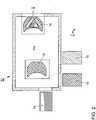
- the prefabricated textile semi-finished fiber products 15 are stacked and stored in a following stacking station III. Depending on requirements, the stacked semi-finished fiber products 15 are transferred to a processing technology downstream Assemblierstation IV, which in the Fig. 2 is indicated. In the assembling station IV, the preimpregnated textile semi-finished fiber products 15 are cut to form a layer package 16 (FIG. Fig. 2 ) stored stacked. In addition, the prepregs 15 stacked on top of the layer package 16 are cut to size according to the load requirements and geometric requirements of the finished plastic component 1. This results in a further material scrap, which is led out of the process chain as an assembly trim residue m A.
- the assembly trim residue m A consists of a composite of fibers and reactive thermoplastic matrix material.
- the fibers are completely surrounded by matrix material, that is to say fully impregnated.
- the fiber content of the assembly trim residue m A is therefore lower than at the edge trim residue m R and substantially identical to the fiber content of the finished plastic component 1.
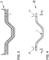
- the layer package 16 becomes the one in which Fig. 3 roughly schematically indicated pressing and / or thermoforming station V transferred, in which the layer package 16 is heated to a temperature above the polymerization temperature and at the same time deep drawn / pressed in the shape of the plastic component 1 to be produced.
- a final trimming is performed on the plastic component 1, in which, for example, an outer component edge 17 required for the thermoforming process is removed from the plastic component 1, to form a final trimming residue m E , which consists of a composite of fibers and polymerized matrix material.
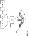
- FIG. 5 is the process chain I to VI for the production of the plastic component 1 assigned a recycling station VII, in which the not yet polymerized Randberough- and Assemblierberough residues m R , m A are performed.
- a cutting mill can be arranged in the recycling station VII, which comminutes the trimming residues m R , m A to predetermined fiber lengths.
- the trimming residues m R , m A are combined to form a recyclate R, which consists of the composite of fibers and reactive thermoplastic matrix material and forms a reactive, not yet polymerized starting material for the production of a further component 19.
- the recycling station VII is followed by a forming station VIII, in which under polymerization of the recyclate R as a result of heat input, the component 19 is produced.
- the forming station VIII may have an only indicated metering device 21, in which the recyclate R is melted to above its melting temperature, but still below its reaction temperature.
- the molten recycled material R is introduced by means of the metering device 21 into the mold cavity 23 of a forming tool 25, which is heated to a temperature above the reaction temperature. This means that after the introduction of the molten recyclate R polymerized in the mold cavity 23.
- the recycling station VII points in the Fig. 5
- a reactive matrix material m matrix and / or optionally additives such as thickeners supplying m trimming residues A,.
Landscapes
- Engineering & Computer Science (AREA)
- Mechanical Engineering (AREA)
- Chemical & Material Sciences (AREA)
- Composite Materials (AREA)
- Environmental & Geological Engineering (AREA)
- Reinforced Plastic Materials (AREA)
- Casting Or Compression Moulding Of Plastics Or The Like (AREA)
- Separation, Recovery Or Treatment Of Waste Materials Containing Plastics (AREA)
- Processing And Handling Of Plastics And Other Materials For Molding In General (AREA)
- Moulding By Coating Moulds (AREA)
Description
- Die Erfindung betrifft eine Prozessanordnung zur Herstellung eines faserverstärkten Kunststoffbauteils nach dem Oberbegriff des Patentanspruches 1 sowie ein Verfahren zur Herstellung eines solchen Kunststoffbauteils nach dem Oberbegriff des Patentanspruches 9.
- Die Herstellung von faserverstärkten Kunststoffbauteilen kann mit Hilfe von textilen Halbzeugen, sogenannten Prepregs, erfolgen. Bei reaktiven Prepregs ist ein textiles Fasermaterial mit einem reaktiven, das heißt noch nicht polymerisierten thermoplastischen Matrixmaterial unterhalb einer Polymerisations-Starttemperatur vorimprägniert. Zur Formgebung des faserverstärkten Kunststoffbauteils werden die Prepregs in einem Ablegevorgang zu einem Lagenpaket übereinandergestapelt und einem Tiefzieh- oder Pressverfahren unterworfen.
- Aus der
WO 2012/116947 A1 ist ein gattungsgemäßes Verfahren zur Herstellung von reaktiven Prepregs, das heißt von endlosfaserverstärkten, flächigen Halbzeugen mit Polyamidmatrix bekannt. In dem Verfahren werden zunächst textile Strukturen mit einer flüssigen Ausgangskomponente der Polyamidmatrix, das heißt geschmolzenes Lactam einschließlich zugegebener Katalysatoren und/oder Aktivatoren, vorimprägniert, und zwar in einem kontinuierlichen Prozess. Nach erfolgter Imprägnierung wird die vorimprägnierte textile Endlos-Struktur in einer Schneidstation zu faserverstärkten flächigen Halbzeugen konfektioniert und in einer Stapelstation übereinander gestapelt. Im weiteren Prozessverlauf werden die vorimprägnierten textilen Halbzeuge zu einer Assemblierstation transportiert, in der die textilen Halbzeuge in einem Ablegevorgang übereinandergelegt und entsprechend der Endkontur des herzustellenden Bauteils zugeschnitten werden. Das so gebildete Lagenpaket wird anschließend in eine Werkzeugform eingelegt. Dann erfolgt die Formgebung, und zwar bei einer Temperatur oberhalb der Polymerisations-Starttemperatur in einem Press- oder Tiefziehvorgang. Auf diese Weise polymerisiert das vorimprägnierte Lactam zu einem Polyamid. Durch das gleichzeitige Tiefziehen/Pressen wird das faserverstärkte, flächige Halbzeug in die beabsichtigte Form des herzustellenden Bauteils gebracht. - Anschließend kann in einer Nachbehandlungsstation ein Endbeschnitt des fertiggestellten Kunststoffbauteils erfolgen, und zwar unter Bildung von Endbeschnitt-Resten, die aus einem Verbund aus Fasern und dem polymerisierten Matrixmaterial bestehen. Die Endbeschnitt-Reste können einer Recyclingstation zugeführt werden und dort zu einem Recyclat für Anwendungen in einem Spritzguss- oder Pressprozess weiterverarbeitet werden, wie es zum Beispiel in der
EP 2 666 805 B1 angedeutet ist. Demzufolge können Bauteile auf Basis einer thermoplastischen Matrix durch ein einfaches Zerkleinern und Extrudieren neuen Anwendungen zum Beispiel im Spritzgussbereich zugeführt werden. Dabei besteht der grundlegende Vorteil von Faserverbundwerkstoffen auf Basis einer thermoplastischen Matrix in der hervorragenden Recyclierungseigenschaft. Durch ein einfaches Aufschmelzen und Regranulieren vermischen sich die Fasern und die Matrix homogen. Das so recyclierte Granulat kann erneut als ein hochwertiger Rohstoff für die verschiedensten Anwendungen eingesetzt werden. - Bei der oben skizzierten Prozesskette besteht die Problematik darin, dass - abgesehen von dem erwähnten Endbeschnitt-Rest - zusätzlich auch zu vorgelagerten Prozesszeitpunkten Randbeschnitt-Reste (aus der Konfektionierung der Faserhalbzeuge) und Assemblierbeschnitt-Reste entstehen. Die Randbeschnitt-Reste und die Assemblierbeschnitt-Reste sind - im Unterschied zum Endbeschnitt-Rest - noch nicht polymerisiert und können daher im oben angegebenen Recyclingprozess nicht weiterverarbeitet werden. Die Randbeschnitt- und Assemblierbeschnitt-Reste werden daher als nicht recyclingfähiger Materialausschuss aus der Prozesskette herausgeführt.
- Aus der
EP 0 443 051 A1 ist ein Recycling von Beschnitt-Resten bekannt, wobei die Beschnitt-Reste Teile bereits ausgehärteter Prepregs sind. Gemäß derWO 2011/056293 A1 werden faserverstärkte Späne zur Herstellung von Verbundbauteilen verwendet. Die Späne werden dabei beispielsweise von einem faserverstärkten vorimprägnierten Werkstoff abgeschnitten. - Die Aufgabe der Erfindung besteht darin, eine Prozessanordnung sowie ein Verfahren zur Herstellung eines faserverstärkten Kunststoffbauteils bereitzustellen, das ein im Vergleich zum Stand der Technik verbessertes Recyclingkonzept aufweist.
- Die Aufgabe der Erfindung ist durch die Merkmale des Patentanspruches 1 oder des Patentanspruches 9 gelöst. Bevorzugte Weiterbildungen der Erfindung sind in den abhängigen Ansprüchen offenbart.
- Gemäß dem kennzeichnenden Teil des Patentanspruches 1 weist die Prozessanordnung eine Recyclingstation auf, in die die Beschnitt-Reste aus dem Verbund aus Fasern und reaktivem thermoplastischem Matrixmaterial zuführbar sind. Die Recyclingstation stellt auf der Grundlage der Beschnitt-Reste ein Recyclat bereit, das als ein reaktives, noch nicht polymerisiertes Ausgangsmaterial für die Herstellung eines Bauteils oder die Funktionalisierung eines Bauteils, zum Beispiel durch Rippenstrukturen, dient.
- In einer bevorzugten Ausführungsvariante kann der Prozessanordnung eine Formgebungsstation zugeordnet sein, in der infolge einer Wärmeeinbringung unter Polymerisation des Recyclats die Herstellung des Bauteils erfolgt. Im Hinblick auf eine einwandfreie Polymerisation in der Formgebungsstation ist es von Relevanz, dass das noch nicht polymerisierte Recyclat nicht in Kontakt mit der Umgebung gelang, das heißt mit der Luftfeuchtigkeit, dem Sauerstoff, der UV-Strahlung oder dergleichen reagiert, wodurch dessen Verarbeitbarkeit, insbesondere die Polymerisation, beeinträchtigt wird. Um eine solche nachteilige Reaktion mit der Umgebung zu vermeiden, kann das Recyclat bis zu seiner Polymerisation getrocknet werden und/oder in luft-, licht- und/oder feuchtigkeitsdichter Abschirmung gelagert werden.
- Die Formgebungsstation kann in einer technischen Umsetzung einen Extruder oder eine Dosiereinrichtung aufweist, in der das Recyclat bis oberhalb seiner Schmelztemperatur, jedoch unterhalb seiner Reaktionstemperatur aufschmelzbar ist. Das aufgeschmolzene Recyclat wird mittels des Extruders oder der Dosiereinrichtung in die Werkzeugkavität eines Formgebungswerkzeugs eingebracht, das bis auf eine Temperatur oberhalb der Reaktionstemperatur aufgeheizt ist. Die Einbringung in das bis auf die Reaktionstemperatur aufgeheizte Werkzeug kann zum Beispiel über die Düse eines Spritzgußaggregates oder über den Injektionskopf einer Dosieranlage in ein offenes oder geschlossenes Formgebungswerkzeug erfolgen.
- Neben der Einbringung in das geschlossene oder geöffnete Werkzeug (zum Beispiel LFT-Pressprozess mit reaktiver Matrix) sind auch andere Verfahren, zum Beispiel das Spritzprägen des Recyclats, denkbar.
- Alternativ dazu kann das Recyclat, ohne vorheriges Aufschmelzen, im festen Aggregatszustand in die Werkzeugkavität des Formgebungswerkzeugs der Formgebungsstation eingebracht werden. In diesem Fall kann das Recyclat zum Beispiel erst bei geschlossener Werkzeugkavität des Formgebungswerkzeug aufgeschmolzen, in der Werkzeugkavität verteilt und darin polymerisiert werden. Eine Kombination mit anderen formgebenden Verfahren, zum Beispiel Pressverfahren reaktiver, endlosfaserverstärkter Guss-PA-Prepregs, ist denkbar. Als Beispiel sei das Hinterspritzen oder-pressen kurzfaserverstärkter Guss-PA-Rippen aus reaktivem Rezyclat erwähnt.
- Die zur Recyclingstation geführten Beschnitt-Reste sind gegebenenfalls so groß, dass sie vor der Weiterverarbeitung als Recyclat zum Beispiel in einer Schneidmühle verkleinert werden. Vorzugsweise liegen nach dem Verkleinerungsvorgang Beschnitt-Reste mit einstellbarer, einheitlicher Faserlänge (Kurz- bis Langfasern) vor. Wie bereits oben angedeutet, müssen zur Vermeidung der Kontamination des reaktiven Matrixmaterials mit Luftfeuchte sowohl die Zwischenlagerung der Beschnitt-Reste vor und nach der Verkleinerung als auch der Schneidmühlenprozess selbst in trockener Atmosphäre erfolgen.
- Die der Recyclingstation zugeführten Beschnitt-Reste können - im Vergleich zum Faservolumentanteil des herzustellenden Bauteils - einen erhöhten Faservolumenanteil aufweisen. Vor diesem Hintergrund können in Abhängigkeit vom erforderlichen Faservolumengehalt des Recyclats den in die Recyclingstation geführten Beschnitt-Resten ein reaktives Matrixmaterial und/oder gegebenenfalls Zusatzstoffe, wie Verdickungsmittel, zusetzbar sein.
- In einer fertigungstechnischen Umsetzung kann in der Fertigungsstation in einem kontinuierlichen Prozess zumindest eine Endlosbahn aus einer textilen Struktur mit einer flüssigen Ausgangskomponente des reaktiven, thermoplastischen Matrixmaterials vorimprägniert werden. Nach erfolgter Imprägnierung wird ein Randbeschnitt durchgeführt, bei dem die vorimprägnierte Endlos-Struktur in einer Schneidstation zu den endlosfaserverstärkten textilen Faserhalbzeugen (Prepregs) mit reaktivem, das heißt noch nicht polymerisiertem, thermoplastischen Matrixmaterial konfektioniert wird. Die Konfektionierung erfolgt unter Bildung von Randbeschnitt-Resten, die aus einem Verbund aus Fasern und reaktivem thermoplastischen Matrixmaterial bestehen. In den Randbeschnitt-Resten sind die Fasern fertigungstechnisch bedingt nicht vollständig mit dem Matrixmaterial benetzt. Die Randbeschnitt-Reste können zum Teil sogar komplett ohne Matrixmaterial vorliegen. Entsprechend ist der Faseranteil in den Randbeschnitt-Resten sehr hoch.
- Im weiteren Prozessverlauf werden die Prepregs in einer Stapelstation übereinandergestapelt und gelagert sowie bei Bedarf zu einer Assemblierstation transportiert. In der Assemblierstation werden die Prepregs in einem Ablegevorgang zu einem Lagenpaket übereinandergeschichtet. Anschließend kann ein Assemblierbeschnitt erfolgen, bei dem das Lagenpaket entsprechend einer Endkontur des faserverstärkten Kunststoffbauteils zugeschnitten wird. Dabei ergeben sich Assemblierbeschnitt-Reste, bestehend aus einem Verbund aus Fasern und reaktivem thermoplastischem Matrixmaterial. Im Unterschied zu dem Randbeschnitt-Resten sind die Assemblierbeschnitt-Reste vollständig von Matrixmaterial umgeben, das heißt vollimprägniert, so dass der Faseranteil dem eines fertiggestellten faserverstärkten Kunststoffbauteils entspricht.
- Als reaktives thermoplastisches Matrixmaterial wird vorzugsweise Caprolactam (sogenanntes Guss-PA) verwendet. Alternative reaktive thermoplastische Matrixsysteme können außer Caprolactam auch zum Beispiel Laurinlactam und zyklisches Buthylentherephtalat, etc. sein. Als Fasermaterial sind alle möglichen Fasern denkbar. Vorzugsweise werden Fasern aus Glas, Kohlenstoff (sogenannte Carbonfasern), Basalt, Aramit oder eine Kombination davon verwendet. Diese liegen in unterschiedlichster Anordnung, wie zum Beispiel Gewebe, Gelege oder undirektional, vor. Die Polymerisation erfolgt bei Carprolactam mittels einer Reaktionstemperatur von ca. 150°C, bei der aus dem Caprolactam das Polyamid (PA6) entsteht. Für andere reaktive Materialien, wie zum Beispiel Laurinlactam zu PA12 oder CBT zu PBT sind dem jeweiligen Material angepasste Temperaturen zu wählen.
- Die vorstehend erläuterten und/oder in den Unteransprüchen wiedergegebenen vorteilhaften Aus- und/oder Weiterbildungen der Erfindung können - außer zum Beispiel eindeutiger Abhängigkeiten oder unvereinbarer Alternativen - einzeln oder aber auch in beliebiger Kombination miteinander zur Anwendung kommen.
- Die Erfindung und ihre vorteilhaften Aus- und Weiterbildungen sowie deren Vorteile werden nachfolgend von Zeichnungen näher erläutert.
- Es zeigen:
- Fig. 1 bis 4
- jeweils Prozessstationen zur Herstellung des faserverstärkten Kunststoffbauteils; und
- Fig. 5
- ein Blockschaltdiagramm der Prozesskette einschließlich einer Recyclingstation.
- In den
Fig. 1 bis 4 sind die Prozessstationen I bis VI zur Herstellung eines faserverstärkten Kunststoffbauteils 1 (Fig. 3 und 4 ) insoweit dargestellt, als es für das Verständnis der Erfindung erforderlich ist. Demzufolge werden in einer Fertigungsstation I zunächst exemplarisch zwei Faserlagen 2 in einem kontinuierlichen Prozess unter Zwischenlage einer ersten Folie 3 aus zum Beispiel Polyamid oder einem anderen geeigneten Material auf ein Endlostransportband 5 gebracht. Die so gebildete textile Lagenstruktur 7 wird mit einer Ausgangskomponente 8 eines reaktiven thermoplastischen Matrixmaterials, etwa Lactam, durchtränkt, und zwar unter Wärmebeaufschlagung 10 bei einer Temperatur unterhalb der Starttemperatur für eine Polymerisation der Ausgangskomponente des reaktiven thermoplastischen Matrixmaterials. Die in derFig. 1 gezeigten Folien 2 und 9 sind rein exemplarisch dargestellt und zur Realisierung der Erfindung nicht erforderlich. - Anschließend wird im weiteren Prozessverlauf noch eine zweite Folie 9 appliziert und die textile Lagenstruktur 7 in einer Kühleinheit 11 abgekühlt (das heißt konsolidiert) sowie in einer nachfolgenden Schneidstation II zu einzelnen vorimprägnierten, textilen Faserhalbzeugen 15 konfektioniert. In der Schneidstation II erfolgt ein Randbeschnitt, bei dem die vorimprägnierte Endlos-Struktur 7 zu den endlosfaserverstärkten textilen Faserhalbzeugen 15 (nachfolgend auch als Prepregs bezeichnet) zugeschnitten wird. Dabei entsteht ein Randbeschnitt-Rest mR, der aus einem Verbund aus Fasern und reaktivem (das heißt noch nicht polymerisiertem) thermoplastischem Matrixmaterial besteht. Der Randbeschnitt-Rest mR wird als Materialausschuss aus der Prozesskette abgeführt. Im Randbeschnitt-Rest mR sind die Fasern nicht vollständig mit dem reaktivem Matrixmaterial benetzt oder liegen diese gänzlich ohne Matrixmaterial vor, wodurch der Randbeschnitt-Rest mR einen sehr hohen Faseranteil aufweist.
- Die konfektionierten textilen Faserhalbzeuge 15 werden in einer folgenden Stapelstation III übereinander gestapelt und gelagert. Je nach Bedarf werden die übereinander gestapelten Faserhalbzeuge 15 zu einer prozesstechnisch nachgeschalteten Assemblierstation IV übertragen, die in der
Fig. 2 angedeutet ist. In der Assemblierstation IV werden die vorimprägnierten, textilen Faserhalbzeuge 15 zugeschnitten und zu einem Lagenpaket 16 (Fig. 2 ) übereinandergeschichtet abgelegt. Zudem werden die zum Lagenpaket 16 übereinandergeschichteten Prepregs 15 entsprechend den Lasterfordernissen und Geometrieanforderungen des fertiggestellten Kunststoffbauteils 1 zugeschnitten. Daraus ergibt sich ein weiterer Materialausschuss, der als ein Assemblierbeschnitt-Rest mA aus der Prozesskette geführt wird. Der Assemblierbeschnitt-Rest mA besteht aus einem Verbund aus Fasern und reaktivem thermoplastischem Matrixmaterial. Im Unterschied zum Randbeschnitt-Rest mR sind im Assemblierbeschnitt-Rest mA die Fasern vollständig von Matrixmaterial umgeben, das heißt vollimprägniert. Der Faseranteil des Assemblierbeschnitt-Rests mA ist daher niedriger als beim Randbeschnitt-Rest mR und im Wesentlichen identisch mit dem Faseranteil des fertiggestellten Kunststoffbauteils 1. - Im weiteren Prozessverlauf wird das Lagenpaket 16 zu der, in der
Fig. 3 grob schematischen angedeuteten Press- und/oder Tiefziehstation V übertragen, in der das Lagenpaket 16 auf eine Temperatur oberhalb der Polymerisationstemperatur erwärmt wird und gleichzeitig in die Form des herzustellenden Kunststoffbauteils 1 tiefgezogen/gepresst wird. In einer prozesstechnisch nachgelagerten Nachbehandlungsstation VI (Fig. 4 ) wird am Kunststoffbauteil 1 ein Endbeschnitt durchgeführt, bei dem beispielhaft ein für den Tiefziehvorgang erforderlicher äußerer Bauteilrand 17 vom Kunststoffbauteil 1 entfernt wird, und zwar unter Bildung eines Endbeschnitt-Rests mE, der aus einem Verbund aus Fasern und polymerisiertem Matrixmaterial besteht. - In der der
Fig. 5 ist der Prozesskette I bis VI zur Herstellung des Kunststoffbauteils 1 eine Recyclingstation VII zugeordnet, in die die noch nicht polymerisierten Randbeschnitt- und Assemblierbeschnitt-Reste mR, mA geführt werden. In der Recyclingstation VII kann gegebenenfalls eine Schneidmühle angeordnet sein, die die Beschnitt-Reste mR, mA bis auf vorgegebene Faserlängen zerkleinert. In der Recyclingstation VII werden die Beschnitt-Reste mR, mA zu einem Recyclat R zusammengefasst, das aus dem Verbund aus Fasern und reaktivem thermoplastischem Matrixmaterial besteht und ein reaktives, noch nicht polymerisiertes Ausgangsmaterial für die Herstellung eines weiteren Bauteils 19 bildet. - Wie aus der
Fig. 5 hervorgeht, ist der Recyclingstation VII eine Formgebungsstation VIII nachgeschaltet, in der unter Polymerisation des Recyclats R infolge Wärmeeinbringung das Bauteil 19 hergestellt wird. In der technischen Ausführung kann die Formgebungsstation VIII eine nur angedeutete Dosiereinrichtung 21 aufweisen, in der das Recyclat R bis oberhalb seiner Schmelztemperatur, jedoch noch unterhalb seiner Reaktionstemperatur aufgeschmolzen wird. Das aufgeschmolzene Recyclat R wird mittels der Dosiereinrichtung 21 in die Werkzeugkavität 23 eines Formgebungswerkzeug 25 eingebracht, das bis auf eine Temperatur oberhalb der Reaktionstemperatur aufgeheizt ist. Das heißt dass nach erfolgter Einbringung das aufgeschmolzene Recyclat R in der Werkzeugkavität 23 polymerisiert. - Die Recyclingstation VII weist in der
Fig. 5 zudem einen Zulauf 27 auf, um den Beschnitt-Resten mA, mR in der Recyclingstation VII ein reaktives Matrixmaterial mmatrix und/oder gegebenenfalls Zusatzstoffe, wie Verdickungsmittel, zuzuführen. Auf diese Weise kann der erforderliche Faservolumengehalt des herzustellenden Bauteils 19 angepasst werden.
Claims (9)
- Prozessanordnung zur Herstellung eines faserverstärkten Kunststoffbauteils (1), mit einer Fertigungs- und Assemblierstation (I, IV) zur Bereitstellung zumindest eines endlosfaserverstärkten textilen Faserhalbzeugs (15) mit reaktivem thermoplastischen Matrixmaterial, und zwar unter Bildung von Beschnitt-Resten (mR, mA) aus einem Verbund aus Fasern und dem reaktiven thermoplastischen Matrixmaterial, und mit einer Press- und/oder Tiefziehstation (V), in der das endlosfaserverstärkte textile Faserhalbzeug (15) mit reaktivem thermoplastischem Matrixmaterial auf eine Temperatur oberhalb der Polymerisationstemperatur erwärmt wird und gleichzeitig in die Form des herzustellenden Kunststoffbauteils (1) pressbar und/oder tiefziehbar ist, dadurch gekennzeichnet, dass die Prozessanordnung eine Recyclingstation (VII) aufweist, in die die Beschnitt-Reste (mR, mA) aus dem Verbund aus Fasern und reaktivem thermoplastischem Matrixmaterial zuführbar sind zur Bereitstellung eines Recyclats (R) als reaktives, noch nicht polymerisiertes Ausgangsmaterial für die Herstellung eines weiteren Bauteils (19) oder für die Funktionalisierung des Bauteils (1).
- Prozessanordnung nach Anspruch 1, dadurch gekennzeichnet, dass die Prozessanordnung eine Formgebungsstation (VIII) aufweist, in der unter Polymerisation des Recyclats (R) infolge Wärmeeinbringung die Herstellung des Bauteils (19) erfolgt.
- Prozessanordnung nach Anspruch 2, dadurch gekennzeichnet, dass die Formgebungsstation (VIII) einen Extruder oder eine Dosiereinrichtung (21) aufweist, in der das Recyclat (R) bis oberhalb seiner Schmelztemperatur, jedoch unterhalb seiner Reaktionstemperatur aufschmelzbar ist, und dass das aufgeschmolzene Recyclat (R) mittels des Extruders oder der Dosiereinrichtung (21) in ein Formgebungswerkzeug (25) einbringbar ist, das bis auf eine Temperatur oberhalb der Reaktionstemperatur aufgeheizt ist.
- Prozessanordnung nach Anspruch 2, dadurch gekennzeichnet, dass das Recyclat (R), ohne vorheriges Aufheizen bis oberhalb seiner Schmelztemperatur, im festen Aggregatszustand in eine Werkzeugkavität (23) des Formgebungswerkzeugs (25) der Formgebungsstation (VIII) einbringbar ist, und dass das Recyclat (R) erst bei geschlossener Werkzeugkavität (23) des Formgebungswerkzeug (25) aufgeschmolzen, in der Werkzeugkavität (23) verteilt und darin polymerisiert wird.
- Prozessanordnung nach einem der vorhergehenden Ansprüche, dadurch gekennzeichnet, dass die Recyclingstation (VII) eine Zerkleinerungseinheit, etwa eine Schneidmühle, aufweist, in der die zugeführten Beschnitt-Reste (mR, mA) bis auf vorgegebene Faserlängen zerkleinerbar sind.
- Prozessanordnung nach Anspruch 3, dadurch gekennzeichnet, dass den in die Recyclingstation (VII) geführten Beschnitt-Resten (mA, mR) ein reaktives Matrixmaterial (mmatrix) und/oder gegebenenfalls Zusatzstoffe, wie Verdickungsmittel, zusetzbar sind.
- Prozessanordnung nach Anspruch 1, dadurch gekennzeichnet, dass in der Fertigungsstation (I) in einem kontinuierlichen Prozess zumindest eine Endlosbahn aus einer textilen Struktur (7) mit einer flüssigen Ausgangskomponente (8) des reaktiven thermoplastischen Matrixmaterials vorimprägnierbar ist, und dass eine Schneidstation (II) bereitgestellt ist, in der nach erfolgter Imprägnierung ein Randbeschnitt erfolgt, bei dem die gebildete vorimprägnierte Endlos-Struktur (7) zu den endlosfaserverstärkten textilen Faserhalbzeugen (15) mit reaktivem thermoplastischem Matrixmaterial konfektionierbar ist, und zwar unter Bildung eines Randbeschnitt-Rests (mR), der aus dem Verbund aus Fasern und reaktivem thermoplastischem Matrixmaterial besteht.
- Prozessanordnung nach Anspruch 1, dadurch gekennzeichnet, dass in der Assemblierstation (IV) die endlosfaserverstärkten textilen Faserhalbzeuge (15) in einem Ablegevorgang zu einem Lagenpaket (16) übereinanderschichtbar sind, oder dass ein Assemblierbeschnitt erfolgt, bei dem das Faserhalbzeug (15) entsprechend einer Endkontur des faserverstärkten Kunststoffbauteils (1) zuschneidbar ist, und zwar unter Bildung eines Assemblierbeschnitt-Rests (mA), der aus dem Verbund aus Fasern und reaktivem thermoplastischem Matrixmaterial besteht.
- Verfahren zur Herstellung eines faserverstärkten Kunststoffbauteils (1) aus zumindest einem endlosfaserverstärkten textilen Faserhalbzeug (15) mit reaktivem thermoplastischem Matrixmaterial, wobei bei der Fertigung des Faserhalbzeugs (15) Beschnitt-Reste (mR, mA) anfallen, die aus einem Verbund aus Fasern und dem reaktiven thermoplastischen Matrixmaterial bestehen, dadurch gekennzeichnet, dass die bei der Fertigung des Faserhalbzeugs (15) anfallenden Beschnitt-Reste (mR, mA) einer Recyclingstation (VII) zugeführt werden zur Bereitstellung eines Recyclats (R) als reaktives, noch nicht polymerisiertes Ausgangsmaterial für die Herstellung eines weiteren Bauteils (19) oder für die Funktionalisierung des Bauteils (1).
Applications Claiming Priority (2)
| Application Number | Priority Date | Filing Date | Title |
|---|---|---|---|
| DE102015002107.9A DE102015002107A1 (de) | 2015-02-23 | 2015-02-23 | Prozessanordnung sowie Verfahren zur Herstellung eines faserverstärkten Kunststoffbauteils |
| PCT/EP2016/000252 WO2016134829A1 (de) | 2015-02-23 | 2016-02-15 | Prozessanordnung sowie verfahren zur herstellung eines faserverstärkten kunststoffbauteils |
Publications (2)
| Publication Number | Publication Date |
|---|---|
| EP3261822A1 EP3261822A1 (de) | 2018-01-03 |
| EP3261822B1 true EP3261822B1 (de) | 2019-04-10 |
Family
ID=55398250
Family Applications (1)
| Application Number | Title | Priority Date | Filing Date |
|---|---|---|---|
| EP16705035.0A Active EP3261822B1 (de) | 2015-02-23 | 2016-02-15 | Prozessanordnung sowie verfahren zur herstellung eines faserverstärkten kunststoffbauteils |
Country Status (7)
| Country | Link |
|---|---|
| US (1) | US10543648B2 (de) |
| EP (1) | EP3261822B1 (de) |
| JP (1) | JP2018507127A (de) |
| KR (1) | KR20170118894A (de) |
| CN (1) | CN107249865B (de) |
| DE (1) | DE102015002107A1 (de) |
| WO (1) | WO2016134829A1 (de) |
Families Citing this family (4)
| Publication number | Priority date | Publication date | Assignee | Title |
|---|---|---|---|---|
| EP3261813B1 (de) | 2015-02-23 | 2020-04-22 | Volkswagen Aktiengesellschaft | Verfahren zur herstellung faserverstärkter bauteile oder halbzeuge |
| EP3294791B1 (de) | 2015-05-12 | 2019-10-02 | Basf Se | Caprolactam formulierungen |
| DE102021126912A1 (de) * | 2021-10-18 | 2023-04-20 | Fraunhofer-Gesellschaft zur Förderung der angewandten Forschung eingetragener Verein | Verfahren zur Herstellung von Sandwichbauteilen aus einem plattenförmigen Sandwichhalbzeug |
| KR102617325B1 (ko) | 2021-12-20 | 2023-12-21 | 김한정 | 와이어컷팅머신 가공수 처리시스템 |
Family Cites Families (15)
| Publication number | Priority date | Publication date | Assignee | Title |
|---|---|---|---|---|
| US3166533A (en) * | 1959-12-16 | 1965-01-19 | Wichterle Otto | Method for the adiabatic production of castings of polycaprolactam and similar polyamides having any required shape and size |
| BE708095A (de) * | 1967-12-15 | 1968-04-16 | ||
| US5445701A (en) * | 1987-05-08 | 1995-08-29 | Research Association For New Technology Development Of High Performance Polymer | Apparatus of manufacturing a sheet-prepreg reinforced with fibers |
| DE59001262D1 (de) * | 1990-02-17 | 1993-05-27 | Fibron Gmbh | Verfahren zur herstellung einer duroplastischen pressmasse aus glasfaser-polyester-verbundwerkstoff |
| DE4112172A1 (de) * | 1991-04-13 | 1992-08-27 | Krupp Ag | Verfahren zur herstellung eines wiederaufbereitbaren faserverbundwerkstoffs aus thermoplastischem kunststoff |
| KR20040071235A (ko) * | 2001-12-20 | 2004-08-11 | 이엠에스-케미에 아게 | 열가소성 매트릭스를 이용한 복합 재료의 제조 방법 |
| US20060073311A1 (en) * | 2004-10-05 | 2006-04-06 | The Boeing Company | Apparatus and method for composite tape profile cutting |
| CN101062595A (zh) * | 2007-05-16 | 2007-10-31 | 陈锦松 | 碳纤维/玻璃纤维复合材料制作过程中废弃边角料的应用及其制品 |
| CN101264667A (zh) * | 2008-04-08 | 2008-09-17 | 浙江大洲固体废物处置研究所 | 利用环氧树脂玻璃纤维布废料生产绝缘板的方法 |
| US8883908B2 (en) * | 2009-06-02 | 2014-11-11 | Johns Manville | Methods for making reinforced thermoplastic composites using reactive fibers and/or reactive flakes |
| US8709319B2 (en) * | 2009-11-06 | 2014-04-29 | The Boeing Company | Compression molding method and reinforced thermoplastic parts molded thereby |
| WO2012116947A1 (de) | 2011-03-03 | 2012-09-07 | Basf Se | Verfahren zur herstellung von faserverstärkten, flachen halbzeugen mit polyamidmatrix |
| FR2981652B1 (fr) * | 2011-10-21 | 2015-03-27 | Arkema France | Composites via la polymerisation in-situ de resines thermoplastiques methacryliques |
| EP2666805B1 (de) | 2012-05-25 | 2014-10-22 | LANXESS Deutschland GmbH | Verfahren zur Herstellung eines Faserverbund-Werkstoffs |
| US9186852B2 (en) * | 2013-11-22 | 2015-11-17 | Johns Manville | Fiber-containing prepregs and methods and systems of making |
-
2015
- 2015-02-23 DE DE102015002107.9A patent/DE102015002107A1/de not_active Withdrawn
-
2016
- 2016-02-15 CN CN201680011481.3A patent/CN107249865B/zh not_active Expired - Fee Related
- 2016-02-15 KR KR1020177026693A patent/KR20170118894A/ko not_active Withdrawn
- 2016-02-15 EP EP16705035.0A patent/EP3261822B1/de active Active
- 2016-02-15 JP JP2017562124A patent/JP2018507127A/ja not_active Withdrawn
- 2016-02-15 WO PCT/EP2016/000252 patent/WO2016134829A1/de not_active Ceased
- 2016-02-15 US US15/552,939 patent/US10543648B2/en active Active
Non-Patent Citations (1)
| Title |
|---|
| None * |
Also Published As
| Publication number | Publication date |
|---|---|
| WO2016134829A1 (de) | 2016-09-01 |
| EP3261822A1 (de) | 2018-01-03 |
| KR20170118894A (ko) | 2017-10-25 |
| US20180050504A1 (en) | 2018-02-22 |
| DE102015002107A1 (de) | 2016-08-25 |
| CN107249865A (zh) | 2017-10-13 |
| CN107249865B (zh) | 2020-01-14 |
| US10543648B2 (en) | 2020-01-28 |
| JP2018507127A (ja) | 2018-03-15 |
Similar Documents
| Publication | Publication Date | Title |
|---|---|---|
| DE102010019625B4 (de) | Verfahren zur Herstellung einer Verbund- oder Hybridkonstruktion | |
| EP3065936B1 (de) | Verfahren zur herstellung eines halbzeugs zur verarbeitung zu einem cfk-bauteil aus kohlefaserabfällen | |
| EP3261823B1 (de) | Prozessanordnung sowie verfahren zur herstellung eines faserverstärkten kunststoffbauteils | |
| DE102008048334A1 (de) | Verfahren und Vorrichtung zum Herstellen von einem faserverstärkten Verbundwerkstoff | |
| WO2015071155A1 (de) | One-shot herstellung von composites | |
| EP3175968A1 (de) | Verfahren zur kontinuierlichen stofflichen verwertung von altfraktionen aus fasern und geweben auf basis von thermoplastischen kunststoffen | |
| WO2016134829A1 (de) | Prozessanordnung sowie verfahren zur herstellung eines faserverstärkten kunststoffbauteils | |
| Dumont et al. | Compression moulding | |
| WO2008055459A2 (de) | Verfahren zur herstellung einer blattfeder aus einem faserverbundwerkstoff mit einem thermoplastischen kunststoff und die so erhaltene blattfeder | |
| DE69810637T2 (de) | Verfahren zum formen eines lasttrageteils aus verstärktem thermoplast | |
| KR101254363B1 (ko) | 장섬유강화 열가소성 플라스틱 재질의 프로파일 제조방법및 그 제조장치 | |
| JP2018507128A5 (de) | ||
| DE102016100947A1 (de) | Kunststoffverbundbauteil und Verfahren zu seiner Herstellung | |
| EP2750846B1 (de) | Verfahren zum herstellen eines faserverbundwerkstoff-zwischenproduktes und verwendung | |
| JP2018507127A5 (de) | ||
| WO2016020252A1 (de) | Sandwich-bauteile aus poly(meth)acrylat-basierten schaumkörpern und reversibel vernetzbaren composites | |
| EP0084135B1 (de) | Verfahren zur Herstellung von Formkörpern aus faserverstärkten Schichtstoffen | |
| EP1428649A1 (de) | Verfahren zur Herstellung von dreidimensionalen Bauteilen | |
| WO2019101396A1 (de) | Verfahren zur herstellung eines faserverbundbauteils und faserverbundbauteil | |
| Dubey et al. | Manufacturing of Wood Polymer Composites | |
| DE102016200530B4 (de) | Verfahren zur Herstellung eines faserverstärkten Kunststoffbauteils | |
| DE19542665A1 (de) | Verfahren zum Herstellen von Hohlkörpern aus langfaserverstärktem Thermoplastwerkstoff | |
| DE102007028872A1 (de) | Verfahren zur Herstellung eines flächigen Strukturverbundbauteils | |
| WO2016001049A1 (de) | One-shot hd-rtm-verfahren | |
| DE102015009660A1 (de) | Verfahren zum Herstellen eines Verbundbauelements, insbesondere für einen Kraftwagen |
Legal Events
| Date | Code | Title | Description |
|---|---|---|---|
| STAA | Information on the status of an ep patent application or granted ep patent |
Free format text: STATUS: THE INTERNATIONAL PUBLICATION HAS BEEN MADE |
|
| PUAI | Public reference made under article 153(3) epc to a published international application that has entered the european phase |
Free format text: ORIGINAL CODE: 0009012 |
|
| STAA | Information on the status of an ep patent application or granted ep patent |
Free format text: STATUS: REQUEST FOR EXAMINATION WAS MADE |
|
| 17P | Request for examination filed |
Effective date: 20170823 |
|
| AK | Designated contracting states |
Kind code of ref document: A1 Designated state(s): AL AT BE BG CH CY CZ DE DK EE ES FI FR GB GR HR HU IE IS IT LI LT LU LV MC MK MT NL NO PL PT RO RS SE SI SK SM TR |
|
| AX | Request for extension of the european patent |
Extension state: BA ME |
|
| RIN1 | Information on inventor provided before grant (corrected) |
Inventor name: EHLEBEN, MAX Inventor name: MERTENS, THOMAS Inventor name: WOLLNY, ANDREAS Inventor name: ZEUNER, KATJA Inventor name: TAEGER, OLAF Inventor name: DESBOIS, PHILIPPE Inventor name: BITTERLICH, MAURICE Inventor name: KUNZE, CHRISTINE |
|
| DAV | Request for validation of the european patent (deleted) | ||
| DAX | Request for extension of the european patent (deleted) | ||
| GRAP | Despatch of communication of intention to grant a patent |
Free format text: ORIGINAL CODE: EPIDOSNIGR1 |
|
| STAA | Information on the status of an ep patent application or granted ep patent |
Free format text: STATUS: GRANT OF PATENT IS INTENDED |
|
| INTG | Intention to grant announced |
Effective date: 20181031 |
|
| GRAS | Grant fee paid |
Free format text: ORIGINAL CODE: EPIDOSNIGR3 |
|
| GRAA | (expected) grant |
Free format text: ORIGINAL CODE: 0009210 |
|
| STAA | Information on the status of an ep patent application or granted ep patent |
Free format text: STATUS: THE PATENT HAS BEEN GRANTED |
|
| AK | Designated contracting states |
Kind code of ref document: B1 Designated state(s): AL AT BE BG CH CY CZ DE DK EE ES FI FR GB GR HR HU IE IS IT LI LT LU LV MC MK MT NL NO PL PT RO RS SE SI SK SM TR |
|
| REG | Reference to a national code |
Ref country code: GB Ref legal event code: FG4D Free format text: NOT ENGLISH |
|
| REG | Reference to a national code |
Ref country code: CH Ref legal event code: EP Ref country code: AT Ref legal event code: REF Ref document number: 1118077 Country of ref document: AT Kind code of ref document: T Effective date: 20190415 |
|
| REG | Reference to a national code |
Ref country code: IE Ref legal event code: FG4D Free format text: LANGUAGE OF EP DOCUMENT: GERMAN |
|
| REG | Reference to a national code |
Ref country code: DE Ref legal event code: R096 Ref document number: 502016004116 Country of ref document: DE |
|
| REG | Reference to a national code |
Ref country code: NL Ref legal event code: MP Effective date: 20190410 |
|
| REG | Reference to a national code |
Ref country code: LT Ref legal event code: MG4D |
|
| PG25 | Lapsed in a contracting state [announced via postgrant information from national office to epo] |
Ref country code: NL Free format text: LAPSE BECAUSE OF FAILURE TO SUBMIT A TRANSLATION OF THE DESCRIPTION OR TO PAY THE FEE WITHIN THE PRESCRIBED TIME-LIMIT Effective date: 20190410 |
|
| PG25 | Lapsed in a contracting state [announced via postgrant information from national office to epo] |
Ref country code: PT Free format text: LAPSE BECAUSE OF FAILURE TO SUBMIT A TRANSLATION OF THE DESCRIPTION OR TO PAY THE FEE WITHIN THE PRESCRIBED TIME-LIMIT Effective date: 20190910 Ref country code: FI Free format text: LAPSE BECAUSE OF FAILURE TO SUBMIT A TRANSLATION OF THE DESCRIPTION OR TO PAY THE FEE WITHIN THE PRESCRIBED TIME-LIMIT Effective date: 20190410 Ref country code: LT Free format text: LAPSE BECAUSE OF FAILURE TO SUBMIT A TRANSLATION OF THE DESCRIPTION OR TO PAY THE FEE WITHIN THE PRESCRIBED TIME-LIMIT Effective date: 20190410 Ref country code: AL Free format text: LAPSE BECAUSE OF FAILURE TO SUBMIT A TRANSLATION OF THE DESCRIPTION OR TO PAY THE FEE WITHIN THE PRESCRIBED TIME-LIMIT Effective date: 20190410 Ref country code: ES Free format text: LAPSE BECAUSE OF FAILURE TO SUBMIT A TRANSLATION OF THE DESCRIPTION OR TO PAY THE FEE WITHIN THE PRESCRIBED TIME-LIMIT Effective date: 20190410 Ref country code: SE Free format text: LAPSE BECAUSE OF FAILURE TO SUBMIT A TRANSLATION OF THE DESCRIPTION OR TO PAY THE FEE WITHIN THE PRESCRIBED TIME-LIMIT Effective date: 20190410 Ref country code: NO Free format text: LAPSE BECAUSE OF FAILURE TO SUBMIT A TRANSLATION OF THE DESCRIPTION OR TO PAY THE FEE WITHIN THE PRESCRIBED TIME-LIMIT Effective date: 20190710 Ref country code: HR Free format text: LAPSE BECAUSE OF FAILURE TO SUBMIT A TRANSLATION OF THE DESCRIPTION OR TO PAY THE FEE WITHIN THE PRESCRIBED TIME-LIMIT Effective date: 20190410 |
|
| PG25 | Lapsed in a contracting state [announced via postgrant information from national office to epo] |
Ref country code: GR Free format text: LAPSE BECAUSE OF FAILURE TO SUBMIT A TRANSLATION OF THE DESCRIPTION OR TO PAY THE FEE WITHIN THE PRESCRIBED TIME-LIMIT Effective date: 20190711 Ref country code: PL Free format text: LAPSE BECAUSE OF FAILURE TO SUBMIT A TRANSLATION OF THE DESCRIPTION OR TO PAY THE FEE WITHIN THE PRESCRIBED TIME-LIMIT Effective date: 20190410 Ref country code: LV Free format text: LAPSE BECAUSE OF FAILURE TO SUBMIT A TRANSLATION OF THE DESCRIPTION OR TO PAY THE FEE WITHIN THE PRESCRIBED TIME-LIMIT Effective date: 20190410 Ref country code: BG Free format text: LAPSE BECAUSE OF FAILURE TO SUBMIT A TRANSLATION OF THE DESCRIPTION OR TO PAY THE FEE WITHIN THE PRESCRIBED TIME-LIMIT Effective date: 20190710 Ref country code: RS Free format text: LAPSE BECAUSE OF FAILURE TO SUBMIT A TRANSLATION OF THE DESCRIPTION OR TO PAY THE FEE WITHIN THE PRESCRIBED TIME-LIMIT Effective date: 20190410 |
|
| PG25 | Lapsed in a contracting state [announced via postgrant information from national office to epo] |
Ref country code: IS Free format text: LAPSE BECAUSE OF FAILURE TO SUBMIT A TRANSLATION OF THE DESCRIPTION OR TO PAY THE FEE WITHIN THE PRESCRIBED TIME-LIMIT Effective date: 20190810 |
|
| REG | Reference to a national code |
Ref country code: DE Ref legal event code: R097 Ref document number: 502016004116 Country of ref document: DE |
|
| REG | Reference to a national code |
Ref country code: DE Ref legal event code: R082 Ref document number: 502016004116 Country of ref document: DE Representative=s name: NEUBAUER LIEBL BIERSCHNEIDER, DE Ref country code: DE Ref legal event code: R081 Ref document number: 502016004116 Country of ref document: DE Owner name: VOLKSWAGEN AKTIENGESELLSCHAFT, DE Free format text: FORMER OWNERS: BASF SE, 67063 LUDWIGSHAFEN, DE; VOLKSWAGEN AKTIENGESELLSCHAFT, 38440 WOLFSBURG, DE Ref country code: DE Ref legal event code: R082 Ref document number: 502016004116 Country of ref document: DE Representative=s name: NEUBAUER LIEBL BIERSCHNEIDER MASSINGER, DE |
|
| PG25 | Lapsed in a contracting state [announced via postgrant information from national office to epo] |
Ref country code: SK Free format text: LAPSE BECAUSE OF FAILURE TO SUBMIT A TRANSLATION OF THE DESCRIPTION OR TO PAY THE FEE WITHIN THE PRESCRIBED TIME-LIMIT Effective date: 20190410 Ref country code: EE Free format text: LAPSE BECAUSE OF FAILURE TO SUBMIT A TRANSLATION OF THE DESCRIPTION OR TO PAY THE FEE WITHIN THE PRESCRIBED TIME-LIMIT Effective date: 20190410 Ref country code: CZ Free format text: LAPSE BECAUSE OF FAILURE TO SUBMIT A TRANSLATION OF THE DESCRIPTION OR TO PAY THE FEE WITHIN THE PRESCRIBED TIME-LIMIT Effective date: 20190410 Ref country code: RO Free format text: LAPSE BECAUSE OF FAILURE TO SUBMIT A TRANSLATION OF THE DESCRIPTION OR TO PAY THE FEE WITHIN THE PRESCRIBED TIME-LIMIT Effective date: 20190410 Ref country code: DK Free format text: LAPSE BECAUSE OF FAILURE TO SUBMIT A TRANSLATION OF THE DESCRIPTION OR TO PAY THE FEE WITHIN THE PRESCRIBED TIME-LIMIT Effective date: 20190410 |
|
| PLBE | No opposition filed within time limit |
Free format text: ORIGINAL CODE: 0009261 |
|
| STAA | Information on the status of an ep patent application or granted ep patent |
Free format text: STATUS: NO OPPOSITION FILED WITHIN TIME LIMIT |
|
| PG25 | Lapsed in a contracting state [announced via postgrant information from national office to epo] |
Ref country code: SM Free format text: LAPSE BECAUSE OF FAILURE TO SUBMIT A TRANSLATION OF THE DESCRIPTION OR TO PAY THE FEE WITHIN THE PRESCRIBED TIME-LIMIT Effective date: 20190410 Ref country code: IT Free format text: LAPSE BECAUSE OF FAILURE TO SUBMIT A TRANSLATION OF THE DESCRIPTION OR TO PAY THE FEE WITHIN THE PRESCRIBED TIME-LIMIT Effective date: 20190410 |
|
| 26N | No opposition filed |
Effective date: 20200113 |
|
| PG25 | Lapsed in a contracting state [announced via postgrant information from national office to epo] |
Ref country code: TR Free format text: LAPSE BECAUSE OF FAILURE TO SUBMIT A TRANSLATION OF THE DESCRIPTION OR TO PAY THE FEE WITHIN THE PRESCRIBED TIME-LIMIT Effective date: 20190410 |
|
| PGFP | Annual fee paid to national office [announced via postgrant information from national office to epo] |
Ref country code: GB Payment date: 20200226 Year of fee payment: 5 |
|
| PG25 | Lapsed in a contracting state [announced via postgrant information from national office to epo] |
Ref country code: SI Free format text: LAPSE BECAUSE OF FAILURE TO SUBMIT A TRANSLATION OF THE DESCRIPTION OR TO PAY THE FEE WITHIN THE PRESCRIBED TIME-LIMIT Effective date: 20190410 |
|
| PGFP | Annual fee paid to national office [announced via postgrant information from national office to epo] |
Ref country code: FR Payment date: 20200225 Year of fee payment: 5 |
|
| REG | Reference to a national code |
Ref country code: CH Ref legal event code: PL |
|
| REG | Reference to a national code |
Ref country code: BE Ref legal event code: MM Effective date: 20200229 |
|
| PG25 | Lapsed in a contracting state [announced via postgrant information from national office to epo] |
Ref country code: LU Free format text: LAPSE BECAUSE OF NON-PAYMENT OF DUE FEES Effective date: 20200215 Ref country code: MC Free format text: LAPSE BECAUSE OF FAILURE TO SUBMIT A TRANSLATION OF THE DESCRIPTION OR TO PAY THE FEE WITHIN THE PRESCRIBED TIME-LIMIT Effective date: 20190410 |
|
| PG25 | Lapsed in a contracting state [announced via postgrant information from national office to epo] |
Ref country code: CH Free format text: LAPSE BECAUSE OF NON-PAYMENT OF DUE FEES Effective date: 20200229 Ref country code: LI Free format text: LAPSE BECAUSE OF NON-PAYMENT OF DUE FEES Effective date: 20200229 |
|
| PG25 | Lapsed in a contracting state [announced via postgrant information from national office to epo] |
Ref country code: IE Free format text: LAPSE BECAUSE OF NON-PAYMENT OF DUE FEES Effective date: 20200215 |
|
| PG25 | Lapsed in a contracting state [announced via postgrant information from national office to epo] |
Ref country code: BE Free format text: LAPSE BECAUSE OF NON-PAYMENT OF DUE FEES Effective date: 20200229 |
|
| GBPC | Gb: european patent ceased through non-payment of renewal fee |
Effective date: 20210215 |
|
| PG25 | Lapsed in a contracting state [announced via postgrant information from national office to epo] |
Ref country code: GB Free format text: LAPSE BECAUSE OF NON-PAYMENT OF DUE FEES Effective date: 20210215 Ref country code: FR Free format text: LAPSE BECAUSE OF NON-PAYMENT OF DUE FEES Effective date: 20210228 |
|
| REG | Reference to a national code |
Ref country code: AT Ref legal event code: MM01 Ref document number: 1118077 Country of ref document: AT Kind code of ref document: T Effective date: 20210215 |
|
| PG25 | Lapsed in a contracting state [announced via postgrant information from national office to epo] |
Ref country code: AT Free format text: LAPSE BECAUSE OF NON-PAYMENT OF DUE FEES Effective date: 20210215 |
|
| PG25 | Lapsed in a contracting state [announced via postgrant information from national office to epo] |
Ref country code: MT Free format text: LAPSE BECAUSE OF FAILURE TO SUBMIT A TRANSLATION OF THE DESCRIPTION OR TO PAY THE FEE WITHIN THE PRESCRIBED TIME-LIMIT Effective date: 20190410 Ref country code: CY Free format text: LAPSE BECAUSE OF FAILURE TO SUBMIT A TRANSLATION OF THE DESCRIPTION OR TO PAY THE FEE WITHIN THE PRESCRIBED TIME-LIMIT Effective date: 20190410 |
|
| PG25 | Lapsed in a contracting state [announced via postgrant information from national office to epo] |
Ref country code: MK Free format text: LAPSE BECAUSE OF FAILURE TO SUBMIT A TRANSLATION OF THE DESCRIPTION OR TO PAY THE FEE WITHIN THE PRESCRIBED TIME-LIMIT Effective date: 20190410 |
|
| REG | Reference to a national code |
Ref country code: DE Ref legal event code: R082 Ref document number: 502016004116 Country of ref document: DE |
|
| PGFP | Annual fee paid to national office [announced via postgrant information from national office to epo] |
Ref country code: DE Payment date: 20240229 Year of fee payment: 9 |
|
| REG | Reference to a national code |
Ref country code: DE Ref legal event code: R119 Ref document number: 502016004116 Country of ref document: DE |
|
| PG25 | Lapsed in a contracting state [announced via postgrant information from national office to epo] |
Ref country code: DE Free format text: LAPSE BECAUSE OF NON-PAYMENT OF DUE FEES Effective date: 20250902 |