EP3261814B1 - A process for manufacturing a fiber reinforced composite article, the composite article obtained and the use thereof - Google Patents
A process for manufacturing a fiber reinforced composite article, the composite article obtained and the use thereof Download PDFInfo
- Publication number
- EP3261814B1 EP3261814B1 EP16702926.3A EP16702926A EP3261814B1 EP 3261814 B1 EP3261814 B1 EP 3261814B1 EP 16702926 A EP16702926 A EP 16702926A EP 3261814 B1 EP3261814 B1 EP 3261814B1
- Authority
- EP
- European Patent Office
- Prior art keywords
- mold
- fibre
- resin
- reinforcement
- lower die
- Prior art date
- Legal status (The legal status is an assumption and is not a legal conclusion. Google has not performed a legal analysis and makes no representation as to the accuracy of the status listed.)
- Active
Links
Images

Classifications
-
- B—PERFORMING OPERATIONS; TRANSPORTING
- B29—WORKING OF PLASTICS; WORKING OF SUBSTANCES IN A PLASTIC STATE IN GENERAL
- B29C—SHAPING OR JOINING OF PLASTICS; SHAPING OF MATERIAL IN A PLASTIC STATE, NOT OTHERWISE PROVIDED FOR; AFTER-TREATMENT OF THE SHAPED PRODUCTS, e.g. REPAIRING
- B29C70/00—Shaping composites, i.e. plastics material comprising reinforcements, fillers or preformed parts, e.g. inserts
- B29C70/04—Shaping composites, i.e. plastics material comprising reinforcements, fillers or preformed parts, e.g. inserts comprising reinforcements only, e.g. self-reinforcing plastics
- B29C70/28—Shaping operations therefor
- B29C70/40—Shaping or impregnating by compression not applied
- B29C70/42—Shaping or impregnating by compression not applied for producing articles of definite length, i.e. discrete articles
- B29C70/46—Shaping or impregnating by compression not applied for producing articles of definite length, i.e. discrete articles using matched moulds, e.g. for deforming sheet moulding compounds [SMC] or prepregs
- B29C70/48—Shaping or impregnating by compression not applied for producing articles of definite length, i.e. discrete articles using matched moulds, e.g. for deforming sheet moulding compounds [SMC] or prepregs and impregnating the reinforcements in the closed mould, e.g. resin transfer moulding [RTM], e.g. by vacuum
-
- B—PERFORMING OPERATIONS; TRANSPORTING
- B29—WORKING OF PLASTICS; WORKING OF SUBSTANCES IN A PLASTIC STATE IN GENERAL
- B29C—SHAPING OR JOINING OF PLASTICS; SHAPING OF MATERIAL IN A PLASTIC STATE, NOT OTHERWISE PROVIDED FOR; AFTER-TREATMENT OF THE SHAPED PRODUCTS, e.g. REPAIRING
- B29C33/00—Moulds or cores; Details thereof or accessories therefor
- B29C33/0038—Moulds or cores; Details thereof or accessories therefor with sealing means or the like
-
- B—PERFORMING OPERATIONS; TRANSPORTING
- B29—WORKING OF PLASTICS; WORKING OF SUBSTANCES IN A PLASTIC STATE IN GENERAL
- B29C—SHAPING OR JOINING OF PLASTICS; SHAPING OF MATERIAL IN A PLASTIC STATE, NOT OTHERWISE PROVIDED FOR; AFTER-TREATMENT OF THE SHAPED PRODUCTS, e.g. REPAIRING
- B29C37/00—Component parts, details, accessories or auxiliary operations, not covered by group B29C33/00 or B29C35/00
- B29C37/006—Degassing moulding material or draining off gas during moulding
- B29C37/0064—Degassing moulding material or draining off gas during moulding of reinforced material
-
- B—PERFORMING OPERATIONS; TRANSPORTING
- B29—WORKING OF PLASTICS; WORKING OF SUBSTANCES IN A PLASTIC STATE IN GENERAL
- B29C—SHAPING OR JOINING OF PLASTICS; SHAPING OF MATERIAL IN A PLASTIC STATE, NOT OTHERWISE PROVIDED FOR; AFTER-TREATMENT OF THE SHAPED PRODUCTS, e.g. REPAIRING
- B29C43/00—Compression moulding, i.e. applying external pressure to flow the moulding material; Apparatus therefor
- B29C43/32—Component parts, details or accessories; Auxiliary operations
- B29C43/36—Moulds for making articles of definite length, i.e. discrete articles
- B29C43/3607—Moulds for making articles of definite length, i.e. discrete articles with sealing means or the like
-
- B—PERFORMING OPERATIONS; TRANSPORTING
- B29—WORKING OF PLASTICS; WORKING OF SUBSTANCES IN A PLASTIC STATE IN GENERAL
- B29C—SHAPING OR JOINING OF PLASTICS; SHAPING OF MATERIAL IN A PLASTIC STATE, NOT OTHERWISE PROVIDED FOR; AFTER-TREATMENT OF THE SHAPED PRODUCTS, e.g. REPAIRING
- B29C70/00—Shaping composites, i.e. plastics material comprising reinforcements, fillers or preformed parts, e.g. inserts
- B29C70/04—Shaping composites, i.e. plastics material comprising reinforcements, fillers or preformed parts, e.g. inserts comprising reinforcements only, e.g. self-reinforcing plastics
- B29C70/28—Shaping operations therefor
- B29C70/40—Shaping or impregnating by compression not applied
- B29C70/42—Shaping or impregnating by compression not applied for producing articles of definite length, i.e. discrete articles
- B29C70/46—Shaping or impregnating by compression not applied for producing articles of definite length, i.e. discrete articles using matched moulds, e.g. for deforming sheet moulding compounds [SMC] or prepregs
- B29C70/467—Shaping or impregnating by compression not applied for producing articles of definite length, i.e. discrete articles using matched moulds, e.g. for deforming sheet moulding compounds [SMC] or prepregs and impregnating the reinforcements during mould closing
-
- B—PERFORMING OPERATIONS; TRANSPORTING
- B29—WORKING OF PLASTICS; WORKING OF SUBSTANCES IN A PLASTIC STATE IN GENERAL
- B29C—SHAPING OR JOINING OF PLASTICS; SHAPING OF MATERIAL IN A PLASTIC STATE, NOT OTHERWISE PROVIDED FOR; AFTER-TREATMENT OF THE SHAPED PRODUCTS, e.g. REPAIRING
- B29C33/00—Moulds or cores; Details thereof or accessories therefor
- B29C33/10—Moulds or cores; Details thereof or accessories therefor with incorporated venting means
-
- B—PERFORMING OPERATIONS; TRANSPORTING
- B29—WORKING OF PLASTICS; WORKING OF SUBSTANCES IN A PLASTIC STATE IN GENERAL
- B29K—INDEXING SCHEME ASSOCIATED WITH SUBCLASSES B29B, B29C OR B29D, RELATING TO MOULDING MATERIALS OR TO MATERIALS FOR MOULDS, REINFORCEMENTS, FILLERS OR PREFORMED PARTS, e.g. INSERTS
- B29K2063/00—Use of EP, i.e. epoxy resins or derivatives thereof, as moulding material
-
- B—PERFORMING OPERATIONS; TRANSPORTING
- B29—WORKING OF PLASTICS; WORKING OF SUBSTANCES IN A PLASTIC STATE IN GENERAL
- B29K—INDEXING SCHEME ASSOCIATED WITH SUBCLASSES B29B, B29C OR B29D, RELATING TO MOULDING MATERIALS OR TO MATERIALS FOR MOULDS, REINFORCEMENTS, FILLERS OR PREFORMED PARTS, e.g. INSERTS
- B29K2301/00—Use of unspecified macromolecular compounds as reinforcement
- B29K2301/10—Thermosetting resins
-
- B—PERFORMING OPERATIONS; TRANSPORTING
- B29—WORKING OF PLASTICS; WORKING OF SUBSTANCES IN A PLASTIC STATE IN GENERAL
- B29L—INDEXING SCHEME ASSOCIATED WITH SUBCLASS B29C, RELATING TO PARTICULAR ARTICLES
- B29L2031/00—Other particular articles
- B29L2031/30—Vehicles, e.g. ships or aircraft, or body parts thereof
- B29L2031/3005—Body finishings
Definitions
- the present invention relates to a process for manufacturing a fibre reinforced composite article by applying a multiple component thermosetting resin composition in accordance with the features of the inventive process according to claim 1, which facilitates manufacturing of composite articles with reduced cycle times.
- the composite articles obtained exhibit high fibre content, low void content and excellent mechanical properties, and can be used for the construction of mass transportation vehicles, in particular in automotive and aerospace industry.
- Molding compounds suitable for this process are prepared prior to molding and are typicaily a mixture of thermoset resin, a suitable curing agent, a chopped fibre reinforcement (typically glass or carbon fibre) and mineral fiilers such as magnesium oxide or calcium carbonate. Mineral fiilers are primarily added to increase the viscosity of the compound to make is suitable for the molding process, as well as reducing the cost of the material.
- the fibre volume content of SMC and BMC compounds is rather low (less than 50%, typicaily in the order of 20 to 30%) and additionally fibre length is often short (less than 50mm).
- High-performance thermoset resin systems such as those based on epoxy, vinyl ester, polyurethane and polyester resins are well known and are used with carbon and glass fibre or other high-strength fibre reinforcements to produce composite parts exhibiting exceptional strength and very light weight. High fibre volume content and the absence of mineral fiilers both contribute to make parts with high strength and low weight.
- High performance resins such as epoxy resins may be pre-mixed with suitable latent hardeners and applied to the fibre reinforcement prior to the molding process to make what is commonly referred to as a prepreg.
- These resins are commonly solid or semi-solid materials, such that the resulting prepreg may be conveniently handled and molded. Molding occurs at elevated temperature in order to reduce the viscosity of the resin and activate the latent hardener, typicaily in a press or autoclave in order to exert pressure and thus consolidate the part.
- the volume fraction of reinforcing fibre in composites made from prepreg materials may be as high as 60-65%, leading to exceptionaily high mechanical properties.
- the preparation of the prepreg material is an additional production step, and the instability of the resin/hardener admixture typically requires cold storage of the material prior to molding. Furthermore, the latency of the hardener required in order to achieve suitable storage stability tends to make the curing time of this material rather long during the molding process. All of this adds cost to the manufacturing process.
- Low viscosity liquid thermoset resins may be used to prepare composite parts by mixing with a suitable curing agent and directly impregnating the dry fibre reinforcement during the molding process. This process facilitates production of light weight and high strength parts of high fibre volume fraction, without the additional cost associated with the prepreg process.
- low viscosity resins are unsuitable for use in the SMC / BMC compression molding process, since this process relies on the high viscosity of the molding compound to achieve the necessary mold pressure to fully consolidate the part and to prevent leakage from the mold.
- the resin transfer molding (RTM) process has been demonstrated to produce composite parts of excellent quality from high-performance liquid resins (low void content, low surface defects, high mechanical properties).
- the fibre reinforcement is placed in a closed mold cavity, which may optionally be evacuated. Resin is then injected into the fibre via an injection gate to impregnate the fibre reinforcement and fill the mold.
- resin injection of the fibre reinforcement occurs predominantly in the plane of the reinforcing fabrics and thus the injection time can be very long depending on part size and the permeability of the fibre reinforcement. Practically, the fibre reinforcement permeability limits the volume fraction of fibre in the final composite, since increasing fibre volume fraction dramatically decreases permeability and therefore lengthens injection time.
- RTM processes variants of RTM are, for example, high-pressure resin transfer molding (HP-RTM) and high-pressure compression resin transfer molding (HP-CRTM).
- HP-RTM high-pressure resin transfer molding
- HP-CRTM high-pressure compression resin transfer molding
- the reactive resin system is injected at high pressure (typically 50 to 150 bar) through the fibre stack in the closed mold cavity, onto which vacuum pressure is typically applied.
- the mold is normally placed in a heavy vertical press in order to prevent the mold from opening under the high injection pressure. Pressure is applied until gelation of the material occurs, which compensates for resin shrinkage occurring during curing. Injection directly onto the fibre stack may cause movement and misalignment of fibres, known as fibre wash, which can lead to reduced mechanical properties of the composite part.
- preforming a process known as preforming.
- use of preformed fibres adds an additional manufacturing step and therefore additional costs.
- HP-CRTM is similar to HP-RTM except that the resin is injected into a partially open mold cavity (also known as gap RTM, where the gap is of the order 0.1 to 2mm).
- a partially open mold increases permeability of the fibre stack and thus reduces injection time.
- the mold is fully closed using a vertical press.
- HP-CRTM requires a compressible mold seal which extends some distance above the die face. The seal enables the mold to be sealed in a partially open position, and must be further compressed in order to fully close the mold cavity. Compression of this seal requires a higher force (and therefore heavier presses) than the HP-RTM described above.
- fibre impregnation is still typically langer than for compression molding, and additionally fibre movement (fibre wash) is significantly increased, since the partially open mold exerts little holding pressure on the fibres during injection.
- Liquid compression molding wherein liquid resin is placed into a mold cavity with the fibre reinforcement and the mold cavity is subsequently closed, is also known to produce composite parts with very short cycle times.
- the resin is typically applied over the surface of the dry fibre reinforcement prior to mold closure, and thus when the mold is closed, impregnation is predominantly through-thickness of the reinforcing fabrics, making it considerably faster than for RTM, where impregnation is in-plane of the fibre reinforcement.
- composite quality is normally compromised compared to the RTM process due to the inclusion of entrapped air bubbles when the mold cavity is closed. Parts often display high void content and surface defects, which may make them unsuitable in applications where mechanical performance and/or visual quality are important factors.
- liquid compression molding relies substantially on the mechanical compaction pressure to achieve complete fibre impregnation upon closure of the mold cavity. Since mechanical pressure is highest in mold planes perpendicular to press closure, but reducing to zero for mold planes aligned to the press closure axis, little mechanical pressure is applied to those areas largely aligned to the press axis. Part production is therefore limited to essentially flat parts, since areas of deep draw created by three dimensional part geometries do not receive sufficient mechanical pressure during mold closure to achieve proper impregnation of the fibre reinforcement. Deep-draw refers to areas of the mold cavity which are substantially aligned to the mold closure axis.
- WO 2013/049966 A1 discloses a method for manufacturing moulded articles of fibre-reinforced resin composite material comprising the steps of: a. disposing a body comprising fibrous reinforcement and resin into a mould cavity portion of a first mould part; b. locating a second mould part relative to the first mould part to form a mutually spaced configuration and to enclose the body within an intermediate mould cavity defined between the spaced first and second mould parts; c. providing a peripheral hermetic seal between the first and second mould parts; d. applying a source of vacuum to the intermediate mould cavity through at least one conduit extending into the intermediate mould cavity, the vacuum extracting air from the intermediate mould cavity; e. moving at least one of first and second mould parts so as relatively to move the first and second mould parts together to define a final mould cavity; and f. heating the body to form the moulded article within the final mould cavity.
- the present invention relates to a process for the preparation of a fibre reinforced composite article comprising the steps of
- thermosetting resin compositions which are liquid at the molding temperature, in particular, liquid resin compositions which have a low viscosity at the molding temperature.
- the viscosity of the thermosetting liquid resin compositions is of from 0.1 to 10'000 mPa.s, preferably, of from 0.1 to 100 mPa.s at the molding temperature.
- Low viscosity resins can advantageously be used for the preparation of composite articles with a fibre volume fraction of 50% or more based on the total volume of the composite article (fibre + resin), because resins of a lower viscosity more easily penetrate into the interfibrous space of the dry reinforcement compared to resins of a higher viscosity.
- the fibre volume fraction of the composite article prepared by the inventive process is in the range of 50 to 60% based on the total volume of the composite article.
- the fibre volume fraction of the composite article prepared by the inventive process is in the range of 60 to 70% based on the total volume of the composite article.
- the mold in the partially closed position in step e) is evacuated to a pressure of from 0.1 to 50 mbar, especially of from 0.1 to 10 mbar.
- the hydraulic pressure exerted onto the resin impregnated reinforcement in step f) is of from 2 to 75 bar, especially of from 10 to 50 bar.
- Hydraulic pressure in the context of the present invention means the pressure in the liquid resin, when press force is applied.
- the process of the present invention is essentially distinguished from RTM, such as HP-RTM, by step b) or c), which step omits injection of the resin at high pressure through the fibre stack in the closed mold.
- WO2014/067865 discloses a mold for resin transfer molding (RTM).
- RTM resin transfer molding
- RTM is carried out by injecting the resin directly into the fibre preform placed in the closed mold cavity to impregnate the fibre reinforcement and fill the mold.
- impregnation of the fibre reinforcement by the process of the present invention is carried out by omitting an injection step, but wetting the surface of the fibre reinforcement with the resin composition, either separately and out of the mold in accordance with step b), or by placing the fibre reinforcement into the lower die of the mold (12). Since resin impregnation of the fibre stack in case of the present invention occurs predominantly through-thickness, fibre movement as observed in RTM is largely eliminated by this configuration.
- the process of the present invention allows for a less sophisticated machine set-up to be applied, since the closed mold does not have to resist the high injection pressure of the resin, i.e. heavy vertical presses to prevent the mold cavity from opening at high injection pressure are not required.
- the preparation of the resin treated fibre reinforcement can be carried out separately and independently from steps d) to h), i.e. the molding and demolding of the reinforced article.
- wetting of the fibre reinforcement is carried out in an automated process, for example, by processes which allow for the wetting of the fibrous reinforcement with the resin onto its surface, for example, dosing, pouring, casting, curtain coating, roller coating or spray application.
- processes which allow for the wetting of the fibrous reinforcement with the resin onto its surface, for example, dosing, pouring, casting, curtain coating, roller coating or spray application.
- step b) which is a preferred embodiment, is advantageously synchronized with the molding and demolding steps d) to h), so that step b) provides the resin treated fibre reinforcement just in time to be available immediately for use in steps d) to h).
- the inventive process enables processing of unbonded fibre reinforcement fabrics.
- Preparation of a partially-bonded fibre preform which adds another process step as disclosed in WO2014/067865 , may be omitted, since fibre misalignment upon resin impregnation is eliminated.
- an internal seal in the fibre preform to avoid leakage of excess resin to contaminate the mold as depicted in Figure 1 of WO02014/067865 can be omitted.
- the mold assembly used in accordance with the process of the present invention provides at least one seal, which also works as a resin retention seal and prevents the resin from leaking, thus allowing for build up of homogeneous pressure over the entire composite part.
- the mold assembly comprises an upper and a lower die with vertically extending side walls (13) and (14) and a seal assembly as indicated above which come together to form a closed mold cavity.
- a vacuum outlet is included either in the upper die (11), or alternatively, in the lower die (12), to allow evacuation of the mold cavity in a partially closed position, with closure of the vacuum outlet occurring prior to full mold closure.
- a vacuum outlet is included in the upper die (11), as shown in Figures 1 and 2 .
- the vacuum outlet (16) is suitably sealed by a valve.
- Figure 1 depicting the mold in a partially closed position in accordance with step d) of the inventive process, the vacuum outlet is open, and the mold is ready to be evacuated in accordance with step e).
- Figure 2 depicting the mold in a completely closed position in accordance with step f) of the inventive process, the vacuum outlet is closed, and the mold is ready for a hydraulic pressure to be exerted onto the resin treated fibre reinforcement to impregnate the fibre reinforcement.
- a vacuum outlet is included in the lower die (12), as shown, for example, in Figure 2 of WO2014/067865 .
- External vacuum chambers are generally bulky and the vacuum which can be achieved may be insufficient to enable for the production of high quality composite articles with visual appearance or surface quality free of any defects.
- At least one gasket/seal (15) is placed around the vertically extending walls of the upper die (11), or the lower die (12), horizontally to the moving direction of the upper die (11).
- the seal is endless, for example, an 0-ring.
- Other seal configurations/ geometries are possible, for example, a square, a rectangular, or a hexagonal shape, corresponding to the cross-sectional shape of the upper die (11), or the lower die (12), perpendicular to the moving direction of the upper die (11) into the lower die (12).
- the cross-sectional shape of the upper and lower die will be determined by the shape of the composite article to be manufactured.
- the at least one seal enables substantial positive pressure (>10 bars) to be generated in step f) upon complete mold closure.
- the at least one seal is a rubbery-elastic, compressible material, for example, a silicone rubber, a polyurethane rubber, a polyacrylate-or polymethacrylate rubber, or a polybutadiene rubber, or a mixture of at least two polymers of the aforementioned group of polymers.
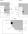
- two seals (15) and (15b), as shown in Figure 3a and Figure 3b are placed around the vertically extending walls of the upper die (11) horizontally to its moving direction.
- a two seal configuration generally improves vacuum-tightness.
- three seals, which further improve vacuum tightness, are placed around the vertically extending walls of the upper die (11) horizontally to its moving direction.
- two seals are placed around the vertically extending walls of the lower die (12) horizontally to the moving direction of the upper die (11). The two or three seals may be aligned parallel to each other.
- the seal being closest to the mold cavity serves as the resin stripping seal, and protects the other seal or seals, which provide for vacuum-tightness, from being contaminated by leaked resin. Since a seal assembly consisting of at least two seals, one vacuum seal and one resin stripping seal, protects the vacuum seal from being contaminated, even after repeated mold cycles, the need for cleaning operations between cycles is largely eliminated, making it highly suited to high-volume production.
- the seal preventing leaked resin from contaminating the vacuum seal may be placed in the lower die (12), for example, in the peripheral section of the lower die's cavity, as shown in the embodiment of Figures 1 and 2 (15b). In accordance with this embodiment, the seal (15b) is more appropriately designated a resin retention seal.
- the process according to the present invention provides for very short mold evacuation times compared to an external vacuum chamber due to the small volume of the mold cavity in the partially closed position, thus enabling very short production cycle times, since fast mold evacuation prior to full mold closure enables use of short gel time resin systems, with correspondingly shorter cure times.
- an internal vertical sliding vacuum chamber with integral sliding seal(s) as realized by the process according to the present invention renders this process highly suitable for use with low-viscosity liquid resin systems and allows for the production of parts of surprisingly high quality (low void content, high fibre volume content, low surface defects) with very short production cycle times.
- Full mold closure occurs when the entire mold cavity is filled, i.e. there are no mechanical stops, so the mold continues to close until pressure is exerted on the liquid resin.
- the seal assembly enables significant pressure to be generated in the mold cavity without any leakage. Hydraulic pressure is generated inside the mold when the press force is applied to the liquid resin contained in the sealed cavity. The pressure generated may be conveniently measured by use of pressure sensors in the mold cavity, such as are known in the art, to control the press force applied. Pressures in the range of 2 to 100 bar, more typically 20 to 50 bar are generated in order to ensure a fully impregnated, void-free composite part.
- the positive hydraulic pressure generated following mold closure enables the fibre reinforcement to be fully impregnated even when deep-draw parts are made offering a significant advantage compared to traditional liquid compression molding. Furthermore, the positive pressure can be maintained throughout curing of the part in order to compensate any shrinkage of the liquid resin, further increasing part quality.
- the process according to the present invention is useful to form various types of composite products, and provides several advantages. Cure times tend to be very short, with good development of polymer properties, such as glass transition temperature Tg.
- thermosetting resins which may be used with the present invention are polyester, vinyl ester, epoxy, polyurethane, polyurea, polyisocyanurate, phenolformaldehyde, melamine, polyimide, benzoxazine, cyanate ester, bismaleimide and acrylic resins, such as those described by Fink, Reactive Polymers Fundamentals and Applications, POL (2013).
- thermosetting resin composition used in accordance with the process of the present invention is an epoxy resin composition.
- the epoxy resin (A) used herein comprises at least one compound or mixture of compounds having an average functionality of at least 2.0 epoxide groups per molecule.
- the epoxy resin or mixture thereof may have an average of up to 4.0 epoxide groups per molecule. It preferably has an average of from 2.0 to 3.0 epoxide groups per molecule.
- the epoxy resin may have an epoxy equivalent weight of about 150 to about 1,000, preferably about 160 to about 300, more preferably from about 170 to about 250. If the epoxy resin is halogenated, the equivalent weight may be somewhat higher.
- Epoxide resins which may be used include polyglycidyl and poly( ⁇ -methylglycidyl) ethers obtainable by the reaction of substances containing per molecule, two or more alcoholic hydroxyl groups, or two or more phenolic hydroxyl groups, with epichlorohydrin, glycerol dichlorohydrin, or ⁇ -methylepichlorohydrin, under alkaline conditions or, alternatively, in the presence of an acidic catalyst with subsequent treatment with alkali.
- Such polyglycidyl ethers may be derived from aliphatic alcohols, for example, ethylene glycol and poly(oxyethylene)glycols such as diethylene glycol and triethylene glycol, propylene glycol and poly(oxypropylene)glycols, propane-1,3-diol, butane-1,4-diol, pentane-1,5-diol, hexane-1,6-diol, hexane-2,4,6-triol, glycerol, 1,1,1-trimethylolpropane, and pentaerythritol; from cycloaliphatic alcohols, such as quinitol, 1,1 bis(hydroxymethyl)cyclohex-3-ene, bis(4-hydroxycyclohexyl)methane, and 2,2-bis(4-hydroxycyclohexyl)-propane; or from alcohols containing aromatic nuclei, such as N,N-bis-(2-hydroxyeth
- the polyglycidyl ethers are derived from substances containing two or more phenolic hydroxyl groups per molecule, for example, resorcinol, catechol, hydroquinone, bis(4-hydroxyphenyl)methane (bisphenol F), 1,1,2,2-tetrakis(4-hydroxyphenyl)ethane, 4,4'-dihydroxydiphenyl, bis(4-hydroxyphenyl)sulphone (bisphenol S), 1,1-bis(4-hydroxylphenyl)-1-phenyl ethane (bisphenol AP), 1,1-bis(4-hydroxylphenyl)ethylene (bisphenol AD), phenolformaldehyde or cresol-formaldehyde novolac resins, 2,2-bis(4-hydroxyphenyl)propane (bisphenol A), and 2,2-bis(3,5-dibromo-4-hydroxyphenyl)propane.
- bisphenol F bis(4-hydroxyphenyl)methane
- poly(N-glycidyl) compounds such as are, for example, obtained by the dehydrochlorination of the reaction products of epichlorohydrin and amines containing at least two hydrogen atoms directly attached to nitrogen, such as aniline, n-butylamine, bis(4-aminophenyl)methane, bis(4-aminophenyl)sulphone, and bis(4-methylaminophenyl)methane.
- poly(N-glycidyl) compounds that may be used include triglycidyl isocyanurate, N,N'-diglycidyl derivatives of cyclic alkylene ureas such as ethyleneurea and 1,3-propyleneurea, and N,N'-diglycidyl derivatives of hydantoins such as 5,5-dimethylhydantoin.
- Epoxide resins obtained by the epoxidation of cyclic and acrylic polyolefins may also be employed, such as vinylcyclohexene dioxide, limonene dioxide, dicyclopentadiene dioxide, 3,4-epoxydihydrodicyclopentadienyl glycidyl ether, the bis(3,4-epoxydihydrodicyclopentadienyl)ether of ethylene glycol, 3,4-epoxycyclohexylmethyl 3 ,4'-epoxycyclohexanecarboxylate and its 6,6'-dimethyl derivative, the bis(3,4-epoxycyclohexanecarboxylate) of ethylene glycol, the acetal formed between 3,4-epoxycyclohexanecarboxyaldehyde and 1,1-bis(hydroxymethyl)-3,4-epoxycyclohexane, bis(2,3-epoxycyclopentyl)ether, and e
- the epoxy resin (A) is the diglycidyl ether of a polyhydric phenol represented by formula (1) H 2 / ⁇ H-C 2 H-0+6-B-6-0-CH ⁇ CH 2
- formula (1) H 2 / ⁇ H-C 2 H-0+6-B-6-0-CH ⁇ CH 2
- (R 1 )m independently denotes
- Each m and each n are independently an integer 0, 1, 2, 3 or 4 and q is a number of from 0 to 5.
- q is the average number of hydroxyl groups in the epoxy resin of formula (1).
- R 1 and R 2 in the meaning of halogen are, for example, chlorine or bromine.
- R 1 and R 2 in the meaning of CrC 4 alkyl are, for example, methyl, ethyl, n-propyl or iso-propyl.
- each B independently in the meaning of a CrC 6 (cylo)-alkylene radical is, for example, methylene, 1,2-ethylene, 1,3-propylene, 1,2-propylene, 2,2-propylene, 1,4-butylene, 1,5-pentylene, 1,6-hexylene or 1,1-cyclohexylene.
- each B independently is methylene, 2,2-propylene or -SOr.
- each m and each n are independently an integer 0, 1 or 2, more preferably 0.
- suitable epoxy resins include diglycidyl ethers of dihydric phenols such as bisphenol A, bisphenol F and bisphenol S, and mixtures thereof.
- Epoxy resins of this type are commercially available, including diglycidyl ethers of bisphenol A resins. Suitable halogenated epoxy resins, wherein at least one of R 1 and R 2 are halogen, are described in, for example, in US4251594 , US4661568 , US4713137 and US4868059 , and Lee and Neville, Handbook of Epoxy Resins, McGraw-Hill (1982 ), all of which are incorporated herein by reference.
- the epoxy resins indicated are either commercially available or can be prepared according to the processes described in the cited documents.
- diglycidyl ethers of polyhydric phenols as given by formula (1) are used, wherein the radicals have the meanings and preferences given above.
- the epoxy resin (A) is the diglycidyl ether of bisphenol A or bisphenol F.
- the viscosity of the epoxy resin composition can be adjusted by adding an epoxy diluent component.
- the epoxy diluent component is, for example, a glycidyl terminated compound.
- compounds containing a glycidyl or ⁇ -methylglycidyl groups directly attached to an atom of oxygen, nitrogen, or sulfur are particularly preferred.
- Such resins include polyglycidyl and poly( ⁇ -methylglycidyl) esters obtainable by the reaction of a substance containing two or more carboxylic acid groups per molecule with epichlorohydrin, glycerol dichlorohydrin, or ⁇ -methylepichlorohydrin in the presence of alkali.
- the polyglycidyl esters may be derived from aliphatic carboxylic acids, e.g. oxalic acid, succinic acid, adipic acid, sebacic acid, or dimerised or trimerised linoleic acid, from cycloaliphatic carboxylic acids such as hexahydro-phthalic, 4-methylhexahydrophthalic, tetrahydrophthalic, and 4-methyltetrahydrophthalic acid, or from aromatic carboxylic acids, such as phthalic acid, isophthalic acid, and terephthalic acid.
- aliphatic carboxylic acids e.g. oxalic acid, succinic acid, adipic acid, sebacic acid, or dimerised or trimerised linoleic acid
- cycloaliphatic carboxylic acids such as hexahydro-phthalic, 4-methylhexahydrophthalic, tetrahydrophthalic, and 4-methyltetrahydro
- the thermosetting epoxy resin composition further comprises a curing agent (B).
- a curing agent (B) amines, for example, primary or secondary amines, acids and acid-anhydrides, lewis acids, lewis bases, phenols.
- the identity of many of these curing agents and their curing mechanisms are discussed in Lee and Neville, Handbook of Epoxy Resins, McGraw-Hill (1982 ).
- amines of which there may be mentioned aliphatic, cycloaliphatic or araliphatic primary and secondary amines, including mixtures of these amines.
- Typical amines include monoethanolamine, N-aminoethyl ethanolamine, ethylenediamine, hexamethylenediamine, trimethylhexamethylenediamines, methylpentamethylenediamines, diethylenetriamine, triethylenetetramine, tetraethylenepentamine, N,N-dimethylpropylenediamine-1,3, N,N-diethylpropylenediamine-1,3, bis(4-amino-3-methylcyclohexyl)methane, bis(p-aminocyclohexyl)methane, 2,2-bis-(4-aminocyclohexyl)propane, 3,5,5-trimethyl-s-(aminomethyl)cyclohexylamine, 1,2-diamin
- Preferred amines include 2,2,4-trimethylhexamethylenediamine, 2,4,4-trimethylhexamethylenediamine, 2-methylpentamethylenediamine, diethylenetriamine, triethylenetetramine, tetraethylenepentamine, 1,2-diaminocyclohexane, bis(p-aminocyclohexyl)methane, m-xylene diamine, norbornene diamine, 3(4),8(9)-bis-(aminomethyl)-tricyclo-[5.2.1.02,6]decane (TCD-diamine), isophorone diamine 1,3-bis(aminomethyl)cyclohexane, and 1,4-bis(aminomethyl)cyclohexane.
- Especially preferred amines include diethylenetriamine, triethylenetetramine, tetraethylenepentamine, 1,2-diaminocyclohexane, m-xylene diamine, 1,3-bis(aminomethyl)cyclohexane, and isophorone diamine.
- the curing agent (B) may be used in combination with an accelerator (C) to adjust the curing rate of the thermosetting resin composition.
- Suitable accelerators for use with epoxy-amine compositions are well described and include alcohols, phenols, acids, tertiary amines, guanidines, boron halide complexes, imidazoles and inorganic metal salts such as calcium nitrate.
- curing step g i.e. curing of the resin impregnated reinforcement, is carried out under, for example, isothermal conditions at a temperature of from 50 to 200°C, preferably of from 100 to 150°C.
- the process according to the present invention allows for the preparation of fibre reinforced composite articles with excellent mechanical properties, such as elongation, fracture toughness, tensile strength and modulus, within a cycle time of less than 10 minutes, preferably less than 5 minutes and most preferably less than 2 minutes.
- the resin composition applied according to inventive process has an appropriate open time after mixing of the components, but the ability to cure rapidly without the need of post-curing.
- the inventive process allows for homogeneous pressure applied over the entire composite part, thereby reduces the size of bubbles also in its peripheral sections, and thus improves the visual appearance of the final composite part. Bubbles are generated by entrapped air and water adsorbed to the fiber reinforcement. In case no resin retention seal is present, the hydraulic pressure of the liquid resin decreases from the center of the composite part to its peripheral area.
- the composite articles obtained according to the inventive process can be used for the construction of consumer goods, such as computer cases or luggage cases, or in the construction of mass transportation vehicles, in particular, in the automotive and aerospace industry.
Landscapes
- Engineering & Computer Science (AREA)
- Mechanical Engineering (AREA)
- Chemical & Material Sciences (AREA)
- Composite Materials (AREA)
- Casting Or Compression Moulding Of Plastics Or The Like (AREA)
- Reinforced Plastic Materials (AREA)
- Moulds For Moulding Plastics Or The Like (AREA)
- Moulding By Coating Moulds (AREA)
- Manufacture Of Alloys Or Alloy Compounds (AREA)
Description
- The present invention relates to a process for manufacturing a fibre reinforced composite article by applying a multiple component thermosetting resin composition in accordance with the features of the inventive process according to claim 1, which facilitates manufacturing of composite articles with reduced cycle times. The composite articles obtained exhibit high fibre content, low void content and excellent mechanical properties, and can be used for the construction of mass transportation vehicles, in particular in automotive and aerospace industry.
- Significant effort in automotive industry is put into the production of lightweight cars to reduce CO2-emission. One effort comprises complete or partial replacement of steel by aluminium. Another effort is replacement of aluminium or steel by composites, which further reduces the weight of cars. However, manufacturing composite body or even chassis parts for cars is demanding as only a few methods are suitable for making complex three-dimensional composite structures. As is the case with many other manufacturing processes, the economics of these composite manufacturing processes is heavily dependent on operating rates. For molding processes, operating rates are often expressed in terms of "cycle time". "Cycle time" represents the time required to produce a part on the mold and prepare the mold to make the next part. Cycle time directly affects the number of parts that can be made on a mold per unit time. Longer cycle times increase manufacturing costs because overhead costs, for example, facilities and labor, are greater per part produced. If greater production capacity is needed, capital costs are also increased, due to the need for more molds and other processing equipment. In order to become competitive with other solutions, cycle times need to be shortened
- Manufacture of composite parts with very short cycle times is already well known by compression molding of SMC (sheet molding compound) and BMC (bulk molding compound). In these processes, the molding compound is compressed in a heated, closed mold cavity until cured, after which it is demolded. The high viscosity of the molding compound enables high pressures to be generated during closure of the mold, which ensures that the material is fully distributed throughout the cavity and is fully consolidated. The mold cavity is normally closed using a line of striction (pinch-off section) at the edge of the part - i.e. a periphery area where the thickness is much reduced compared to the part thickness. When the molding compound reaches the line of striction, its viscosity is sufficiently high that the material is substantiaily prevented from passing. Molding compounds suitable for this process are prepared prior to molding and are typicaily a mixture of thermoset resin, a suitable curing agent, a chopped fibre reinforcement (typically glass or carbon fibre) and mineral fiilers such as magnesium oxide or calcium carbonate. Mineral fiilers are primarily added to increase the viscosity of the compound to make is suitable for the molding process, as weil as reducing the cost of the material. The fibre volume content of SMC and BMC compounds is rather low (less than 50%, typicaily in the order of 20 to 30%) and additionally fibre length is often short (less than 50mm). Since the properties of a composite material depend largely on the strength and orientation of the fibre reinforcement, mechanical performance of parts made using these processes is therefore also low. Non-optimal fibre orientation induced by flow during the molding process further reduces mechanical performance. Weight of parts made with this material is typicaily high due to the high density of the mineral fiilers necessary to achieve the high viscosity of the molding compound.
- High-performance thermoset resin systems such as those based on epoxy, vinyl ester, polyurethane and polyester resins are weil known and are used with carbon and glass fibre or other high-strength fibre reinforcements to produce composite parts exhibiting exceptional strength and very light weight. High fibre volume content and the absence of mineral fiilers both contribute to make parts with high strength and low weight.
- High performance resins such as epoxy resins may be pre-mixed with suitable latent hardeners and applied to the fibre reinforcement prior to the molding process to make what is commonly referred to as a prepreg. These resins are commonly solid or semi-solid materials, such that the resulting prepreg may be conveniently handled and molded. Molding occurs at elevated temperature in order to reduce the viscosity of the resin and activate the latent hardener, typicaily in a press or autoclave in order to exert pressure and thus consolidate the part. The volume fraction of reinforcing fibre in composites made from prepreg materials may be as high as 60-65%, leading to exceptionaily high mechanical properties. However, the preparation of the prepreg material is an additional production step, and the instability of the resin/hardener admixture typically requires cold storage of the material prior to molding. Furthermore, the latency of the hardener required in order to achieve suitable storage stability tends to make the curing time of this material rather long during the molding process. All of this adds cost to the manufacturing process.
- Low viscosity liquid thermoset resins may be used to prepare composite parts by mixing with a suitable curing agent and directly impregnating the dry fibre reinforcement during the molding process. This process facilitates production of light weight and high strength parts of high fibre volume fraction, without the additional cost associated with the prepreg process. However, low viscosity resins are unsuitable for use in the SMC / BMC compression molding process, since this process relies on the high viscosity of the molding compound to achieve the necessary mold pressure to fully consolidate the part and to prevent leakage from the mold.
- The resin transfer molding (RTM) process has been demonstrated to produce composite parts of excellent quality from high-performance liquid resins (low void content, low surface defects, high mechanical properties). In this process, the fibre reinforcement is placed in a closed mold cavity, which may optionally be evacuated. Resin is then injected into the fibre via an injection gate to impregnate the fibre reinforcement and fill the mold. However, resin injection of the fibre reinforcement occurs predominantly in the plane of the reinforcing fabrics and thus the injection time can be very long depending on part size and the permeability of the fibre reinforcement. Practically, the fibre reinforcement permeability limits the volume fraction of fibre in the final composite, since increasing fibre volume fraction dramatically decreases permeability and therefore lengthens injection time. For high-volume production where cycle time is an important consideration, fibre volume fractions in excess of 55% are usually impractical using the RTM process due to the long injection times. The relatively long injection time of parts made with the RTM process requires resin systems which remain liquid throughout the injection step. Decreasing the reactivity of the resin system to ensure that it remains liquid throughout injection normally leads to a correspondingly langer eure time before the part can be demolded. Production cycle times are therefore langer for the RTM process than for compression molding.
- Process variants of RTM are, for example, high-pressure resin transfer molding (HP-RTM) and high-pressure compression resin transfer molding (HP-CRTM).
- In case of HP-RTM the reactive resin system is injected at high pressure (typically 50 to 150 bar) through the fibre stack in the closed mold cavity, onto which vacuum pressure is typically applied. The mold is normally placed in a heavy vertical press in order to prevent the mold from opening under the high injection pressure. Pressure is applied until gelation of the material occurs, which compensates for resin shrinkage occurring during curing. Injection directly onto the fibre stack may cause movement and misalignment of fibres, known as fibre wash, which can lead to reduced mechanical properties of the composite part. In order to minimise this effect, it is normal practice to partially bond the fibre stack in a process known as preforming. However, use of preformed fibres adds an additional manufacturing step and therefore additional costs.
- HP-CRTM is similar to HP-RTM except that the resin is injected into a partially open mold cavity (also known as gap RTM, where the gap is of the order 0.1 to 2mm). A partially open mold increases permeability of the fibre stack and thus reduces injection time. Upon injection, the mold is fully closed using a vertical press. HP-CRTM requires a compressible mold seal which extends some distance above the die face. The seal enables the mold to be sealed in a partially open position, and must be further compressed in order to fully close the mold cavity. Compression of this seal requires a higher force (and therefore heavier presses) than the HP-RTM described above. Whilst this process can decrease the injection time compared to standard HP-RTM, fibre impregnation is still typically langer than for compression molding, and additionally fibre movement (fibre wash) is significantly increased, since the partially open mold exerts little holding pressure on the fibres during injection.
- Liquid compression molding wherein liquid resin is placed into a mold cavity with the fibre reinforcement and the mold cavity is subsequently closed, is also known to produce composite parts with very short cycle times. The resin is typically applied over the surface of the dry fibre reinforcement prior to mold closure, and thus when the mold is closed, impregnation is predominantly through-thickness of the reinforcing fabrics, making it considerably faster than for RTM, where impregnation is in-plane of the fibre reinforcement. However, composite quality is normally compromised compared to the RTM process due to the inclusion of entrapped air bubbles when the mold cavity is closed. Parts often display high void content and surface defects, which may make them unsuitable in applications where mechanical performance and/or visual quality are important factors. Another disadvantage compared to RTM is that liquid compression molding relies substantially on the mechanical compaction pressure to achieve complete fibre impregnation upon closure of the mold cavity. Since mechanical pressure is highest in mold planes perpendicular to press closure, but reducing to zero for mold planes aligned to the press closure axis, little mechanical pressure is applied to those areas largely aligned to the press axis. Part production is therefore limited to essentially flat parts, since areas of deep draw created by three dimensional part geometries do not receive sufficient mechanical pressure during mold closure to achieve proper impregnation of the fibre reinforcement. Deep-draw refers to areas of the mold cavity which are substantially aligned to the mold closure axis. In this process it is common practice to oversize the part dimensions in order to enable entrapped air bubbles to be pushed into the periphery (waste) area of the part, or to incorporate excess resin channels at the edge of the part for the same purpose. These peripheral areas need to be removed by trimming the part to its final dimensions which leads to a high wastage of resin and fibres. It is not uncommon to have 50 to 100% resin and fibre excess wastage on each part. Since the mold is not sealed, pressure in the mold cavity remains low and no compensation of resin shrinkage is possible. Part geometry is limited to substantially flat parts due to the mechanical pressure required for fibre impregnation.
- In vacuum assisted liquid compression molding the process is as described above, but the compression mold is placed into a vacuum chamber and vacuum is applied prior to fully closing the mold. Whilst this process solves some of the issues associated with liquid compression molding (less wastage, reduced porosity), part geometry is still limited to substantially flat parts. Moreover, due to the size of an external vacuum chamber, the time required to evacuate to a pressure suitable to produce high quality parts necessarily lengthens the cycle time. Also, the overall vacuum level consistently achievable in an external vacuum chamber may be limited by mechanical design of the vacuum seal, compromising the final part quality.
-
WO 2013/049966 A1 discloses a method for manufacturing moulded articles of fibre-reinforced resin composite material comprising the steps of: a. disposing a body comprising fibrous reinforcement and resin into a mould cavity portion of a first mould part; b. locating a second mould part relative to the first mould part to form a mutually spaced configuration and to enclose the body within an intermediate mould cavity defined between the spaced first and second mould parts; c. providing a peripheral hermetic seal between the first and second mould parts; d. applying a source of vacuum to the intermediate mould cavity through at least one conduit extending into the intermediate mould cavity, the vacuum extracting air from the intermediate mould cavity; e. moving at least one of first and second mould parts so as relatively to move the first and second mould parts together to define a final mould cavity; and f. heating the body to form the moulded article within the final mould cavity. - The processes for the preparation of fiber reinforced composite articles available today which are useful, for example, for the production of lightweight vehicles, still have some disadvantages in respect of either the quality of the composite parts, i.e. the mechanical properties do not meet the specifications required, and/or the parts cannot be produced at sufficiently short cycle times. Also the visual appearance may be poor and therefore does not satisfy expectations set today in the automotive industry. Accordingly, there is still a need for an improved process which facilitates manufacturing of composite articles with reduced cycle
times, wherein the composite articles exhibit high fibre content, low void content and excellent mechanical properties, for example tensile strength and modulus, and can be used for the construction of mass transportation vehicles, in particular in automotive and aerospace industry. - Accordingly, the present invention relates to a process for the preparation of a fibre reinforced composite article comprising the steps of
- a) providing a mold, comprising an upper die (11) and a lower die (12), the lower die (12) having a molding surface and vertically extending side walls (14), the upper die (11) having a complementary molding surface and vertically extending side walls (13) substantially aligned with the side walls of the lower die, so that the upper die vertically moves into the lower die to form a cavity (17) in a partially and completely closed position of the mold, wherein the cavity (17) in a partially closed position is sealed vacuum-tight by at least one seal (15) placed around the vertically extending side walls (13) of the upper die (11), or the vertically extending side walls (14) of the lower die (12), horizontally to the moving direction of the upper die (11), and wherein the at least one seal (15) also works as a resin retention seal which prevents the resin from leaking,
- b) applying a thermosetting resin composition onto a fibre reinforcement, and placing the thus treated fibre reinforcement into the lower die of the mold (12), or
- c) placing a fibre reinforcement into the lower die of the mold (12), and applying a thermosetting resin composition onto the fibre reinforcement,
- d) moving the upper die (11) into the lower die (12) and partially closing the mold,
- e) evacuating the mold in the partially closed position by means of a vacuum outlet to a pressure of from 0.1 to 100 mbar,
- f) completely closing the mold and exerting a hydraulic pressure of from 2 to 100 bar onto the resin treated reinforcement to complete impregnation of the fibre reinforcement,
- g) curing the resin impregnated reinforcement,
- h) demolding the cured composite article.
- The process according to the present invention is suitable for the processing of thermosetting resin compositions which are liquid at the molding temperature, in particular, liquid resin compositions which have a low viscosity at the molding temperature. In a certain embodiment the viscosity of the thermosetting liquid resin compositions is of from 0.1 to 10'000 mPa.s, preferably, of from 0.1 to 100 mPa.s at the molding temperature.
- Low viscosity resins can advantageously be used for the preparation of composite articles with a fibre volume fraction of 50% or more based on the total volume of the composite article (fibre + resin), because resins of a lower viscosity more easily penetrate into the interfibrous space of the dry reinforcement compared to resins of a higher viscosity. In one embodiment the fibre volume fraction of the composite article prepared by the inventive process is in the range of 50 to 60% based on the total volume of the composite article. In another embodiment the fibre volume fraction of the composite article prepared by the inventive process is in the range of 60 to 70% based on the total volume of the composite article.
- In a preferred embodiment of the present invention the mold in the partially closed position in step e) is evacuated to a pressure of from 0.1 to 50 mbar, especially of from 0.1 to 10 mbar.
- In a preferred embodiment of the present invention the hydraulic pressure exerted onto the resin impregnated reinforcement in step f) is of from 2 to 75 bar, especially of from 10 to 50 bar. Hydraulic pressure in the context of the present invention means the pressure in the liquid resin, when press force is applied.
- The process of the present invention is essentially distinguished from RTM, such as HP-RTM, by step b) or c), which step omits injection of the resin at high pressure through the fibre stack in the closed mold.
-
WO2014/067865 discloses a mold for resin transfer molding (RTM). As indicated above, and in contrast to the present invention, RTM is carried out by injecting the resin directly into the fibre preform placed in the closed mold cavity to impregnate the fibre reinforcement and fill the mold. In contrast, impregnation of the fibre reinforcement by the process of the present invention is carried out by omitting an injection step, but wetting the surface of the fibre reinforcement with the resin composition, either separately and out of the mold in accordance with step b), or by placing the fibre reinforcement into the lower die of the mold (12). Since resin impregnation of the fibre stack in case of the present invention occurs predominantly through-thickness, fibre movement as observed in RTM is largely eliminated by this configuration. Moreover, the process of the present invention allows for a less sophisticated machine set-up to be applied, since the closed mold does not have to resist the high injection pressure of the resin, i.e. heavy vertical presses to prevent the mold cavity from opening at high injection pressure are not required. - In accordance with step b) of the present invention, the preparation of the resin treated fibre reinforcement can be carried out separately and independently from steps d) to h), i.e. the molding and demolding of the reinforced article.
- Advantageously, wetting of the fibre reinforcement is carried out in an automated process, for example, by processes which allow for the wetting of the fibrous reinforcement with the resin onto its surface, for example, dosing, pouring, casting, curtain coating, roller coating or spray application. Such processes are known per se to someone of ordinary skill, for example in the field of textile fibre processing.
- Wetting according to step b), which is a preferred embodiment, is advantageously synchronized with the molding and demolding steps d) to h), so that step b) provides the resin treated fibre reinforcement just in time to be available immediately for use in steps d) to h).
- The inventive process enables processing of unbonded fibre reinforcement fabrics. Preparation of a partially-bonded fibre preform, which adds another process step as disclosed in
WO2014/067865 , may be omitted, since fibre misalignment upon resin impregnation is eliminated. Moreover, an internal seal in the fibre preform to avoid leakage of excess resin to contaminate the mold as depicted inFigure 1 ofWO02014/067865 - The mold assembly comprises an upper and a lower die with vertically extending side walls (13) and (14) and a seal assembly as indicated above which come together to form a closed mold cavity. A vacuum outlet is included either in the upper die (11), or alternatively, in the lower die (12), to allow evacuation of the mold cavity in a partially closed position, with closure of the vacuum outlet occurring prior to full mold closure.
- In a certain embodiment of the inventive process, a vacuum outlet is included in the upper die (11), as shown in
Figures 1 and 2 . In this embodiment, the vacuum outlet (16) is suitably sealed by a valve. InFigure 1 , depicting the mold in a partially closed position in accordance with step d) of the inventive process, the vacuum outlet is open, and the mold is ready to be evacuated in accordance with step e). InFigure 2 , depicting the mold in a completely closed position in accordance with step f) of the inventive process, the vacuum outlet is closed, and the mold is ready for a hydraulic pressure to be exerted onto the resin treated fibre reinforcement to impregnate the fibre reinforcement. - In another embodiment of the inventive process, a vacuum outlet is included in the lower die (12), as shown, for example, in
Figure 2 ofWO2014/067865 . - In vacuum assisted liquid compression molding an external vacuum chamber is normally constructed around the mold. External vacuum chambers are generally bulky and the vacuum which can be achieved may be insufficient to enable for the production of high quality composite articles with visual appearance or surface quality free of any defects.
- In order to provide for vacuum-tightness of the mold in its partially closed or closed position, at least one gasket/seal (15) is placed around the vertically extending walls of the upper die (11), or the lower die (12), horizontally to the moving direction of the upper die (11). In one embodiment the seal is endless, for example, an 0-ring. Other seal configurations/ geometries are possible, for example, a square, a rectangular, or a hexagonal shape, corresponding to the cross-sectional shape of the upper die (11), or the lower die (12), perpendicular to the moving direction of the upper die (11) into the lower die (12). Appropriately, the cross-sectional shape of the upper and lower die will be determined by the shape of the composite article to be manufactured. Moreover, the at least one seal enables substantial positive pressure (>10 bars) to be generated in step f) upon complete mold closure.
- In one embodiment of the present invention the at least one seal is a rubbery-elastic, compressible material, for example, a silicone rubber, a polyurethane rubber, a polyacrylate-or polymethacrylate rubber, or a polybutadiene rubber, or a mixture of at least two polymers of the aforementioned group of polymers.
- In one embodiment two seals (15) and (15b), as shown in
Figure 3a and Figure 3b , are placed around the vertically extending walls of the upper die (11) horizontally to its moving direction. A two seal configuration generally improves vacuum-tightness. In another embodiment, three seals, which further improve vacuum tightness, are placed around the vertically extending walls of the upper die (11) horizontally to its moving direction. In yet another embodiment, two seals are placed around the vertically extending walls of the lower die (12) horizontally to the moving direction of the upper die (11). The two or three seals may be aligned parallel to each other. In case of two or three seals, the seal being closest to the mold cavity serves as the resin stripping seal, and protects the other seal or seals, which provide for vacuum-tightness, from being contaminated by leaked resin. Since a seal assembly consisting of at least two seals, one vacuum seal and one resin stripping seal, protects the vacuum seal from being contaminated, even after repeated mold cycles, the need for cleaning operations between cycles is largely eliminated, making it highly suited to high-volume production. Alternatively, the seal preventing leaked resin from contaminating the vacuum seal may be placed in the lower die (12), for example, in the peripheral section of the lower die's cavity, as shown in the embodiment ofFigures 1 and 2 (15b). In accordance with this embodiment, the seal (15b) is more appropriately designated a resin retention seal. - The process according to the present invention provides for very short mold evacuation times compared to an external vacuum chamber due to the small volume of the mold cavity in the partially closed position, thus enabling very short production cycle times, since fast mold evacuation prior to full mold closure enables use of short gel time resin systems, with correspondingly shorter cure times.
- When processing low viscosity liquid resins, a line of striction (pinch-off section) in the peripheral area of the mold cavity, as known from the processing of more viscous resin compositions by compression molding, will hardly prevent low viscosity resin from passing the line of striction and escaping into the peripheral sections of the mold. This solution is therefore not feasible for industrial processing of low-viscosity liquid resins. However, an internal vertical sliding vacuum chamber with integral sliding seal(s) as realized by the process according to the present invention, in particular the use of a two seal assembly, one vacuum seal and one resin stripping or resin retention seal, renders this process highly suitable for use with low-viscosity liquid resin systems and allows for the production of parts of surprisingly high quality (low void content, high fibre volume content, low surface defects) with very short production cycle times.
- The use of two or more seals described in this invention prevents liquid resin from contaminating the vacuum seal, thus allowing vacuum levels of 10 mbar or less to be consistently and reliably achieved, so that composite parts produced are void free and display very high visual quality and mechanical performance.
- Full mold closure occurs when the entire mold cavity is filled, i.e. there are no mechanical stops, so the mold continues to close until pressure is exerted on the liquid resin. The seal assembly enables significant pressure to be generated in the mold cavity without any leakage. Hydraulic pressure is generated inside the mold when the press force is applied to the liquid resin contained in the sealed cavity. The pressure generated may be conveniently measured by use of pressure sensors in the mold cavity, such as are known in the art, to control the press force applied. Pressures in the range of 2 to 100 bar, more typically 20 to 50 bar are generated in order to ensure a fully impregnated, void-free composite part.
- The positive hydraulic pressure generated following mold closure enables the fibre reinforcement to be fully impregnated even when deep-draw parts are made offering a significant advantage compared to traditional liquid compression molding. Furthermore, the positive pressure can be maintained throughout curing of the part in order to compensate any shrinkage of the liquid resin, further increasing part quality.
- The process according to the present invention is useful to form various types of composite products, and provides several advantages. Cure times tend to be very short, with good development of polymer properties, such as glass transition temperature Tg.
- Examples of thermosetting resins which may be used with the present invention are polyester, vinyl ester, epoxy, polyurethane, polyurea, polyisocyanurate, phenolformaldehyde, melamine, polyimide, benzoxazine, cyanate ester, bismaleimide and acrylic resins, such as those described by Fink, Reactive Polymers Fundamentals and Applications, POL (2013).
- In a preferred embodiment, the thermosetting resin composition used in accordance with the process of the present invention is an epoxy resin composition.
- The epoxy resin (A) used herein comprises at least one compound or mixture of compounds having an average functionality of at least 2.0 epoxide groups per molecule. The epoxy resin or mixture thereof may have an average of up to 4.0 epoxide groups per molecule. It preferably has an average of from 2.0 to 3.0 epoxide groups per molecule.
- The epoxy resin may have an epoxy equivalent weight of about 150 to about 1,000, preferably about 160 to about 300, more preferably from about 170 to about 250. If the epoxy resin is halogenated, the equivalent weight may be somewhat higher.
- Epoxide resins which may be used include polyglycidyl and poly(β-methylglycidyl) ethers obtainable by the reaction of substances containing per molecule, two or more alcoholic hydroxyl groups, or two or more phenolic hydroxyl groups, with epichlorohydrin, glycerol dichlorohydrin, or β-methylepichlorohydrin, under alkaline conditions or, alternatively, in the presence of an acidic catalyst with subsequent treatment with alkali.
- Such polyglycidyl ethers may be derived from aliphatic alcohols, for example, ethylene glycol and poly(oxyethylene)glycols such as diethylene glycol and triethylene glycol, propylene glycol and poly(oxypropylene)glycols, propane-1,3-diol, butane-1,4-diol, pentane-1,5-diol, hexane-1,6-diol, hexane-2,4,6-triol, glycerol, 1,1,1-trimethylolpropane, and pentaerythritol; from cycloaliphatic alcohols, such as quinitol, 1,1 bis(hydroxymethyl)cyclohex-3-ene, bis(4-hydroxycyclohexyl)methane, and 2,2-bis(4-hydroxycyclohexyl)-propane; or from alcohols containing aromatic nuclei, such as N,N-bis-(2-hydroxyethyl)aniline and 4,4'-bis(2-hydroxyethylamino)diphenylmethane.
- Preferably the polyglycidyl ethers are derived from substances containing two or more phenolic hydroxyl groups per molecule, for example, resorcinol, catechol, hydroquinone, bis(4-hydroxyphenyl)methane (bisphenol F), 1,1,2,2-tetrakis(4-hydroxyphenyl)ethane, 4,4'-dihydroxydiphenyl, bis(4-hydroxyphenyl)sulphone (bisphenol S), 1,1-bis(4-hydroxylphenyl)-1-phenyl ethane (bisphenol AP), 1,1-bis(4-hydroxylphenyl)ethylene (bisphenol AD), phenolformaldehyde or cresol-formaldehyde novolac resins, 2,2-bis(4-hydroxyphenyl)propane (bisphenol A), and 2,2-bis(3,5-dibromo-4-hydroxyphenyl)propane.
- There may further be employed poly(N-glycidyl) compounds, such as are, for example, obtained by the dehydrochlorination of the reaction products of epichlorohydrin and amines containing at least two hydrogen atoms directly attached to nitrogen, such as aniline, n-butylamine, bis(4-aminophenyl)methane, bis(4-aminophenyl)sulphone, and bis(4-methylaminophenyl)methane. Other poly(N-glycidyl) compounds that may be used include triglycidyl isocyanurate, N,N'-diglycidyl derivatives of cyclic alkylene ureas such as ethyleneurea and 1,3-propyleneurea, and N,N'-diglycidyl derivatives of hydantoins such as 5,5-dimethylhydantoin.
- Epoxide resins obtained by the epoxidation of cyclic and acrylic polyolefins may also be employed, such as vinylcyclohexene dioxide, limonene dioxide, dicyclopentadiene dioxide, 3,4-epoxydihydrodicyclopentadienyl glycidyl ether, the bis(3,4-epoxydihydrodicyclopentadienyl)ether of ethylene glycol, 3,4-epoxycyclohexylmethyl 3 ,4'-epoxycyclohexanecarboxylate and its 6,6'-dimethyl derivative, the bis(3,4-epoxycyclohexanecarboxylate) of ethylene glycol, the acetal formed between 3,4-epoxycyclohexanecarboxyaldehyde and 1,1-bis(hydroxymethyl)-3,4-epoxycyclohexane, bis(2,3-epoxycyclopentyl)ether, and epoxidized butadiene or copolymers of butadiene with ethylenic compounds such as styrene and vinyl acetate.
- In one embodiment of the present invention, the epoxy resin (A) is the diglycidyl ether of a polyhydric phenol represented by formula (1)

H2/\H-C2H-0+6-B-6-0-CH÷CH2|qO-Q-B-6-O-CH2-C CH2
wherein (R1)m independently denotes m substituents selected from the group consisting of CrC4alkyl and halogen, (R2)n independently denotes n substituents selected from the group consisting of CrC4alkyl and halogen, each B independently is -S-, -S-S-, -SO-, -SOr, -C03-, -CO-, -0-, or a CrC6(cylo)alkylene radical. Each m and each n are independently an integer 0, 1, 2, 3 or 4 and q is a number of from 0 to 5. q is the average number of hydroxyl groups in the epoxy resin of formula (1). R1 and R2 in the meaning of halogen are, for example, chlorine or bromine. R1 and R2 in the meaning of CrC4alkyl are, for example, methyl, ethyl, n-propyl or iso-propyl. B independently in the meaning of a CrC6(cylo)-alkylene radical is, for example, methylene, 1,2-ethylene, 1,3-propylene, 1,2-propylene, 2,2-propylene, 1,4-butylene, 1,5-pentylene, 1,6-hexylene or 1,1-cyclohexylene. Preferably, each B independently is methylene, 2,2-propylene or -SOr. Preferably, each m and each n are independently an integer 0, 1 or 2, more preferably 0. Examples of suitable epoxy resins include diglycidyl ethers of dihydric phenols such as bisphenol A, bisphenol F and bisphenol S, and mixtures thereof. Epoxy resins of this type are commercially available, including diglycidyl ethers of bisphenol A resins. Suitable halogenated epoxy resins, wherein at least one of R1 and R2 are halogen, are described in, for example, inUS4251594 ,US4661568 ,US4713137 andUS4868059 , and Lee and Neville, Handbook of Epoxy Resins, McGraw-Hill (1982), all of which are incorporated herein by reference. - The epoxy resins indicated are either commercially available or can be prepared according to the processes described in the cited documents.
- In a preferred embodiment of the present invention diglycidyl ethers of polyhydric phenols as given by formula (1) are used, wherein the radicals have the meanings and preferences given above. Especially, the epoxy resin (A) is the diglycidyl ether of bisphenol A or bisphenol F.
- If required, the viscosity of the epoxy resin composition can be adjusted by adding an epoxy diluent component. The epoxy diluent component is, for example, a glycidyl terminated compound. Especially preferred are compounds containing a glycidyl or β-methylglycidyl groups directly attached to an atom of oxygen, nitrogen, or sulfur. Such resins include polyglycidyl and poly(β-methylglycidyl) esters obtainable by the reaction of a substance containing two or more carboxylic acid groups per molecule with epichlorohydrin, glycerol dichlorohydrin, or β-methylepichlorohydrin in the presence of alkali. The polyglycidyl esters may be derived from aliphatic carboxylic acids, e.g. oxalic acid, succinic acid, adipic acid, sebacic acid, or dimerised or trimerised linoleic acid, from cycloaliphatic carboxylic acids such as hexahydro-phthalic, 4-methylhexahydrophthalic, tetrahydrophthalic, and 4-methyltetrahydrophthalic acid, or from aromatic carboxylic acids, such as phthalic acid, isophthalic acid, and terephthalic acid.
- The thermosetting epoxy resin composition further comprises a curing agent (B). According to the process of the present invention there come into consideration as the curing agent (B) amines, for example, primary or secondary amines, acids and acid-anhydrides, lewis acids, lewis bases, phenols. The identity of many of these curing agents and their curing mechanisms are discussed in Lee and Neville, Handbook of Epoxy Resins, McGraw-Hill (1982).
- Particularly suited to the present invention are amines, of which there may be mentioned aliphatic, cycloaliphatic or araliphatic primary and secondary amines, including mixtures of these amines. Typical amines include monoethanolamine, N-aminoethyl ethanolamine, ethylenediamine, hexamethylenediamine, trimethylhexamethylenediamines, methylpentamethylenediamines, diethylenetriamine, triethylenetetramine, tetraethylenepentamine, N,N-dimethylpropylenediamine-1,3, N,N-diethylpropylenediamine-1,3, bis(4-amino-3-methylcyclohexyl)methane, bis(p-aminocyclohexyl)methane, 2,2-bis-(4-aminocyclohexyl)propane, 3,5,5-trimethyl-s-(aminomethyl)cyclohexylamine, 1,2-diaminocyclohexane, 1,4-diaminocyclohexane, 1,3-bis(aminomethyl)cyclohexane, 1,4-bis(aminomethyl)cyclohexane, N-aminoethylpiperazine, m-xylene diamine, norbornene diamine, 3(4),8(9)-bis-(aminomethyl)-tricyclo-[5.2.1.02,6]decane (TCD-diamine), and isophorone diamine. Preferred amines include 2,2,4-trimethylhexamethylenediamine, 2,4,4-trimethylhexamethylenediamine, 2-methylpentamethylenediamine, diethylenetriamine, triethylenetetramine, tetraethylenepentamine, 1,2-diaminocyclohexane, bis(p-aminocyclohexyl)methane, m-xylene diamine, norbornene diamine, 3(4),8(9)-bis-(aminomethyl)-tricyclo-[5.2.1.02,6]decane (TCD-diamine), isophorone diamine 1,3-bis(aminomethyl)cyclohexane, and 1,4-bis(aminomethyl)cyclohexane. Especially preferred amines include diethylenetriamine, triethylenetetramine, tetraethylenepentamine, 1,2-diaminocyclohexane, m-xylene diamine, 1,3-bis(aminomethyl)cyclohexane, and isophorone diamine.
- According to the process of the present invention the curing agent (B) may be used in combination with an accelerator (C) to adjust the curing rate of the thermosetting resin composition. Suitable accelerators for use with epoxy-amine compositions are well described and include alcohols, phenols, acids, tertiary amines, guanidines, boron halide complexes, imidazoles and inorganic metal salts such as calcium nitrate.
- According to the process of the present invention, curing step g), i.e. curing of the resin impregnated reinforcement, is carried out under, for example, isothermal conditions at a temperature of from 50 to 200°C, preferably of from 100 to 150°C.
- The process according to the present invention allows for the preparation of fibre reinforced composite articles with excellent mechanical properties, such as elongation, fracture toughness, tensile strength and modulus, within a cycle time of less than 10 minutes, preferably less than 5 minutes and most preferably less than 2 minutes. The resin composition applied according to inventive process has an appropriate open time after mixing of the components, but the ability to cure rapidly without the need of post-curing.
- The inventive process allows for homogeneous pressure applied over the entire composite part, thereby reduces the size of bubbles also in its peripheral sections, and thus improves the visual appearance of the final composite part. Bubbles are generated by entrapped air and water adsorbed to the fiber reinforcement. In case no resin retention seal is present, the hydraulic pressure of the liquid resin decreases from the center of the composite part to its peripheral area.
- The composite articles obtained according to the inventive process can be used for the construction of consumer goods, such as computer cases or luggage cases, or in the construction of mass transportation vehicles, in particular, in the automotive and aerospace industry.
- The following serves to further illustrate the invention. Unless otherwise indicated, the temperatures are given in degrees Celsius, parts are parts by weight and percentages relate to % by weight. Parts by weight relate to parts by volume in a ratio of kilograms to litres.
- 1. A carbon fibre reinforcement fabric (Hexforce 48300 / Hexforce MBBOO, Hexcel, Stamford, US) is cut to size and piled in a stack. Binders may optionally be applied to the single fabrics to improve handling of the fabric layers during cutting and placement.
- 2. A predetermined, measured amount of the thermosetting resin composition containing 100 parts of ARALDITE® LY 3585 (an epoxy resin available from Huntsman Corporation), 21 parts of ARADUR® 3475 (a curing agent available from Huntsman Corporation), and 2 parts of Evomold 3202 (a release agent available from KVS Eckert & Woelk GmbH) is applied to the fibre reinforcement stack and the fibre stack is placed into the lower die of the mold (12) depicted in
Figure 3a . In advance of being applied to the fibre reinforcement, the resin components are mixed by an automated mixing/dosing equipment. - 3. The mold is partially closed, by moving the upper die (11) into the lower die (12), so that the seals (15) and (15b) placed around the vertically extending wall of the upper die (11), horizontally to its moving direction, are in contact with the vertically extending wall of the lower die (12) to form a vacuum tight cavity (see
Figure 3a ). - 4. The cavity formed by the mold in the partially closed position according to step 3 is evacuated to a pressure of 10 mbar or lower.
- 5. Once the required vacuum is achieved, the mold is fully closed (see
Figure 3b ). - 6. Press force is applied to the closed mold, such as to generate a positive hydraulic pressure onto the resin inside the mold. Mold pressure is increased up to 20 to 50 bars, which ensures complete impregnation of the fibre stack, even in areas where the cavity is partially or completely axially aligned to the press force (deep draw areas). Careful adjustment of the resin quantity and press force applied to the fibre stack ensures that the mold is completely filled and that sufficient pressure is generated during closure.
- 7. Press force is applied to the impregnated fibre reinforcement in the closed position of the mold for sufficient time that the resin system reacts and becomes cured. The mold is heated to a temperature of 140°C prior to molding in order to reduce the time needed to eure the resin and the mold temperature is maintained at 140°C for approximately 1 minute.
- 8. The mold is opened and the finished part is removed. Demolding of the finished part may be facilitated by use of mechanical or pneumatic ejectors, such as are know in the art, or by a combination of these.
-
-
Figures 1 and 2 show an example of the mold used in accordance with the present invention comprising an upper die (11) and lower die (12) forming a mold cavity (17) and vertically extended walls (13) and (14) with a seal (15) to create an internal vacuum chamber and additional seal (15b) to retain the liquid resin.Figure 1 depicts the mold in a partially closed position, wherein the vacuum seal (15) is in contact with the vertically extending wall of the lower die (14).Figure 2 depicts the mold in a completely closed position, whereby the vacuum seal (15) effectively closes the mold cavity, and the resin retention seal (15b) prevents the resin from leaking. -
Figure 3a and Figure 3b depict the detailed view of another embodiment, wherein the additional seal (15b) is placed around the vertically extending walls of the upper die (11).Figure 3a depicts the mold in a partially closed position, wherein the vacuum seal (15) and the additional seal (15b), the resin stripping seal, is in contact with the vertically extending walls of the lower die (14). In this partially closed position the mold cavity (17) can be effectively evacuated through an appropriately placed vacuum outlet.Figure 3b depicts the mold in a completely closed position. To improve vacuum-tightness, the vertically extending walls (14) of the lower die may be inclined at an angle of a few degrees (18), for example, of from 1 to 3 degrees, so that the seal (15b) is compressed further. -
Figure 4 depicts the mold in a completely closed position, which is the embodiment ofFigure 3b in scaled-up illustration. An angled geometry of constant thickness (19) enables easy demold of a composite article with no thin cured resin flash. The inclination of the vertically extending walls (14) can either be (i) locally across a certain limited area (18) as shown in the embodiment ofFigure 4 , or (ii) across the entire length of the walls (14) from top to bottom. In the latter case (ii), the inclination angle is appropriately smaller than in the first case (i).
| Properties of the thermosetting resin composition | |||
| Viscosity | Cone-plate viscometer | 25°C | 1020 mPa.s |
| 140°C | <10 mPa.s | ||
| Gel time | Hot plate | 140°C | 21 s |
| Properties of the composite prepared | |||
| Composite laminate construction: 6 layers 300 g!mL carbon fibre fabric ±45° / 0° / 0° / 0° / 0° / ±45° | |||
| Laminate curing: 55s at 140°C | |||
| Plate quality | Visual / micrograph of cut and polished laminate section | Plate 1: Vf = 50% | No defects / no voids |
| Plate 2: Vf = 60% | No defects / no voids | ||
| Plate 3: Vf = 65% | No defects / no voids | ||
| Properties of Plate 1 (Vf = 50%) | |||
| Glass transition temperature (Tg) | OMA ISO 6721 2°C/min | Tg onset | 111°C |
| Tg mid-point | 126°C | ||
| Interlaminar shear strength | ASTM 02344 | 61 MPa | |
| Impact resistance | Charpy ISO 179 | 187 kJ/m2 | |
| Vf : fibre volume fraction in composite article (plates 1 to 3); calculated from the part thickness together with weight of the resin composition and the fibre reinforcement fabric |
Claims (10)
- A process for the preparation of a fibre reinforced composite article comprising the steps ofa) providing a mold, comprising an upper die (11) and a lower die (12), the lower die (12) having a molding surface and vertically extending side walls (14), the upper die (11) having a complementary molding surface and vertically extending side walls (13) substantially aligned with the side walls of the lower die, so that the upper die vertically moves into the lower die to form a cavity (17) in a partially and completely closed position of the mold, wherein the cavity (17) in a partially closed position is sealed vacuum-tight by at least one seal (15) placed around the vertically extending side walls (13) of the upper die (11), or the vertically extending side walls (14) of the lower die (12), horizontally to the moving direction of the upper die (11), and wherein the at least one seal (15) also works as a resin retention seal which prevents the resin from leaking,b) applying a thermosetting resin composition onto a fibre reinforcement, and placing the thus treated fibre reinforcement into the lower die of the mold (12), orc) placing a fibre reinforcement into the lower die of the mold (12), and applying a thermosetting resin composition onto the fibre reinforcement,d) moving the upper die (11) into the lower die (12) and partially closing the mold,e) evacuating the mold in the partially closed position by means of a vacuum outlet to a pressure of from 0.1 to 100 mbar,f) completely closing the mold and exerting a hydraulic pressure of from 2 to 100 bar onto the resin treated reinforcement to complete impregnation of the fibre reinforcement,g) curing the resin impregnated reinforcement,h) demolding the cured composite article.
- The process according to claim 1, wherein the mold in the partially closed position in step e) is evacuated to a pressure of from 0.1 to 50 mbar, especially of from 0.1 to 10 mbar.
- The process according to either claim 1 or claim 2, wherein the hydraulic pressure exerted onto the resin treated reinforcement in step f) is of from 2 to 75 bar, preferably of from 10 to 50 bar.
- The process according to any one of claims 1 to 3, wherein curing of the resin impregnated reinforcement in step g) is carried out under isothermal conditions at a temperature of from 50 to 200°C, preferably of from 100 to 150°C.
- The process according to any one of claims 1 to 4, wherein the composite article prepared has a fibre volume fraction of 50% or more, based on the total volume of the composite article, i.e. fibre and resin.
- The process according to any one of claims 1 to 5, wherein at least two seals (15) and (15b) are placed around the vertically extending wall of the upper die (11) horizontally to its moving direction, substantially aligned parallel to each other, in order to provide for vacuum-tightness of the cavity in a partially and completely closed position of the mold.
- The process according to any one of claims 1 to 6, wherein the thermosetting resin composition is liquid at the molding temperature.
- The process according to claim 7, wherein the thermosetting resin composition has a viscosity of from 0.1 to 10'000 mPa.s, preferably, of from 0.1 to 100 mPa.s at the molding temperature.
- The process according to any one of claims 1 to 8, wherein the thermosetting resin composition is an epoxy resin composition, comprising an epoxy resin (A).
- The process according to claim 9, wherein the epoxy resin (A) is the diglycidylether of bisphenol A or bisphenol F.
Applications Claiming Priority (2)
| Application Number | Priority Date | Filing Date | Title |
|---|---|---|---|
| EP15156848 | 2015-02-27 | ||
| PCT/EP2016/052330 WO2016134937A1 (en) | 2015-02-27 | 2016-02-04 | A process for manufacturing a fiber reinforced composite article, the composite article obtained and the use thereof |
Publications (2)
| Publication Number | Publication Date |
|---|---|
| EP3261814A1 EP3261814A1 (en) | 2018-01-03 |
| EP3261814B1 true EP3261814B1 (en) | 2023-04-19 |
Family
ID=52627023
Family Applications (1)
| Application Number | Title | Priority Date | Filing Date |
|---|---|---|---|
| EP16702926.3A Active EP3261814B1 (en) | 2015-02-27 | 2016-02-04 | A process for manufacturing a fiber reinforced composite article, the composite article obtained and the use thereof |
Country Status (10)
| Country | Link |
|---|---|
| US (1) | US11325326B2 (en) |
| EP (1) | EP3261814B1 (en) |
| JP (1) | JP6735754B2 (en) |
| KR (1) | KR102393762B1 (en) |
| CN (1) | CN107530985B (en) |
| AU (1) | AU2016223748B2 (en) |
| BR (1) | BR112017015847B1 (en) |
| CA (1) | CA2973167C (en) |
| ES (1) | ES2949449T3 (en) |
| WO (1) | WO2016134937A1 (en) |
Families Citing this family (17)
| Publication number | Priority date | Publication date | Assignee | Title |
|---|---|---|---|---|
| WO2017219139A1 (en) * | 2016-06-23 | 2017-12-28 | Fpinnovations | Wood pulp fiber- or cellulose filament-reinforced bulk molding compounds, composites, compositions and methods for preparation thereof |
| US12459178B2 (en) * | 2016-07-22 | 2025-11-04 | Crocs, Inc. | Methods and apparatus for injection and manufacture of molded components with vacuum assist |
| DE102017205843A1 (en) * | 2017-04-06 | 2018-10-11 | Bayerische Motoren Werke Aktiengesellschaft | Tool for producing fiber-reinforced plastic molded parts |
| CN107415280B (en) * | 2017-08-22 | 2023-08-01 | 中国商用飞机有限责任公司北京民用飞机技术研究中心 | Mold and method for preforming and/or positioning T-stringers with wall panels |
| FI130116B (en) | 2018-09-21 | 2023-03-03 | Woodio Oy | Process for the production of shaped products |
| CN109382956A (en) * | 2018-11-09 | 2019-02-26 | 北京航天新风机械设备有限责任公司 | A kind of anti-heat insulating component dead size molding die of abnormal complex and method |
| FR3099080B1 (en) * | 2019-07-22 | 2022-11-04 | Arkema France | METHOD FOR MANUFACTURING A PART IN COMPOSITE MATERIAL USING A MOLD WITH THIN WALLS |
| CN110920096A (en) * | 2019-10-24 | 2020-03-27 | 天津中德应用技术大学 | A kind of molding process of carbon fiber reinforced composite material |
| CN110920097A (en) * | 2019-10-24 | 2020-03-27 | 天津中德应用技术大学 | A kind of preparation method of carbon fiber reinforced resin matrix composite material board |
| CN110948906B (en) * | 2019-12-09 | 2024-07-19 | 宁波市益普乐模塑有限公司 | Manufacturing process of carbon fiber automobile door outer plate |
| JP7394739B2 (en) * | 2020-11-11 | 2023-12-08 | Towa株式会社 | Compression molds, resin molding equipment, resin molding systems, and methods for manufacturing resin molded products |
| CN112341234A (en) * | 2020-11-24 | 2021-02-09 | 中国科学院金属研究所 | Preparation method of low-cost and high-strength fiber-reinforced nano porous carbon composite material |
| WO2022229547A1 (en) * | 2021-04-28 | 2022-11-03 | Safran Aircraft Engines | Device for moulding a bladed part of a turbine engine |
| FR3137603B1 (en) * | 2022-07-08 | 2024-07-19 | Institut De Recherche Tech Materiaux Metallurgie Procedes | Injection mold assembly, particularly for RTM type processes |
| KR20240068275A (en) | 2022-11-10 | 2024-05-17 | 현대자동차주식회사 | A method of manufacturing composite materials and a device for manufacturing composite materials |
| US12358241B2 (en) * | 2023-03-31 | 2025-07-15 | The Boeing Company | Systems and methods for forming composite structures using resin infusion |
| NO20240852A1 (en) * | 2024-08-20 | 2026-02-23 | Nfm As | Anti-ballistic plate consolidation tool and appurtenant method |
Family Cites Families (18)
| Publication number | Priority date | Publication date | Assignee | Title |
|---|---|---|---|---|
| US4323623A (en) * | 1977-09-14 | 1982-04-06 | Mcdonnell Douglas Corporation | Composite plastic structure and method for producing same |
| US4251594A (en) | 1979-09-27 | 1981-02-17 | The Dow Chemical Company | Process for preparing resin impregnated substrates for use in preparing electrical laminates |
| US4551085A (en) | 1983-04-25 | 1985-11-05 | The Budd Company | Compression molding apparatus having vacuum chamber |
| CA1276358C (en) | 1984-01-31 | 1990-11-13 | Dieter H. Klein | Epoxy resin for preparing electric laminates |
| GB8519290D0 (en) | 1985-07-31 | 1985-09-04 | Dow Chemical Rheinwerk Gmbh | Resin composition |
| US4868059A (en) | 1987-11-16 | 1989-09-19 | The Dow Chemical Company | Curable composition containing a difunctional epoxy resin, a polyfunctional epoxy resin, a difunctional phenol and a polyfunctional phenol |
| JPH07256673A (en) * | 1994-03-23 | 1995-10-09 | Sekisui Chem Co Ltd | Press molding method and molding die for fiber-reinforced resin molding |
| EP1566394B2 (en) | 2002-11-28 | 2015-08-26 | Mitsubishi Rayon Co., Ltd. | PROCESSES FOR PRODUCIng FIBER-REINFORCED COMPOSITE MATERIAL |
| CA2506326A1 (en) * | 2002-12-20 | 2004-07-15 | Dow Global Technologies Inc. | Near net shape prepreg |
| US20060220273A1 (en) * | 2005-03-29 | 2006-10-05 | Armstrong Bradford D | Process for compression moulding liquid resins with structural reinforcements |
| JP2006341536A (en) * | 2005-06-10 | 2006-12-21 | Shin Kobe Electric Mach Co Ltd | Injection mold and method for producing molded product using this mold |
| JP2013022835A (en) * | 2011-07-21 | 2013-02-04 | Mitsubishi Heavy Ind Ltd | Method and apparatus for producing at least two products including fiber-reinforced resin |
| WO2013049966A1 (en) * | 2011-10-08 | 2013-04-11 | Gurit (Uk) Ltd. | Manufacturing moulded articles of fibre-reinforced resin composite material |
| BR112014017498B1 (en) * | 2012-01-25 | 2020-12-08 | Hexcel Holding Gmbh | impression material or structure comprising a fibrous reinforcement layer and a curable liquid resin |
| JP2013209510A (en) * | 2012-03-30 | 2013-10-10 | Dainippon Toryo Co Ltd | Fiber-reinforced resin molding coating composition, fiber-reinforced resin molding obtained by applying the coating composition, and method for producing the fiber-reinforced resin molding |
| JP5876791B2 (en) * | 2012-08-28 | 2016-03-02 | 本田技研工業株式会社 | Method and apparatus for molding fiber reinforced resin molded product |
| DE102012110354B4 (en) | 2012-10-29 | 2021-11-18 | Dieffenbacher GmbH Maschinen- und Anlagenbau | Molding tool, control means, method and system for producing a, preferably fiber-reinforced, plastic component |
| CN103963318B (en) * | 2013-01-29 | 2019-08-09 | 康廷南拓结构塑料有限公司 | Vacuum forming method for thermosetting sheet products |
-
2016
- 2016-02-04 CA CA2973167A patent/CA2973167C/en active Active
- 2016-02-04 JP JP2017534593A patent/JP6735754B2/en active Active
- 2016-02-04 ES ES16702926T patent/ES2949449T3/en active Active
- 2016-02-04 BR BR112017015847-7A patent/BR112017015847B1/en active IP Right Grant
- 2016-02-04 US US15/553,617 patent/US11325326B2/en active Active
- 2016-02-04 CN CN201680012194.4A patent/CN107530985B/en active Active
- 2016-02-04 KR KR1020177021466A patent/KR102393762B1/en active Active
- 2016-02-04 AU AU2016223748A patent/AU2016223748B2/en active Active
- 2016-02-04 WO PCT/EP2016/052330 patent/WO2016134937A1/en not_active Ceased
- 2016-02-04 EP EP16702926.3A patent/EP3261814B1/en active Active
Also Published As
| Publication number | Publication date |
|---|---|
| ES2949449T3 (en) | 2023-09-28 |
| JP6735754B2 (en) | 2020-08-05 |
| AU2016223748B2 (en) | 2020-07-09 |
| CN107530985A (en) | 2018-01-02 |
| US20180029315A1 (en) | 2018-02-01 |
| US11325326B2 (en) | 2022-05-10 |
| KR102393762B1 (en) | 2022-05-04 |
| JP2018507795A (en) | 2018-03-22 |
| CA2973167C (en) | 2023-09-05 |
| CA2973167A1 (en) | 2016-09-01 |
| KR20170120101A (en) | 2017-10-30 |
| AU2016223748A1 (en) | 2017-07-13 |
| BR112017015847B1 (en) | 2022-05-24 |
| BR112017015847A2 (en) | 2018-03-27 |
| WO2016134937A1 (en) | 2016-09-01 |
| CN107530985B (en) | 2020-06-19 |
| EP3261814A1 (en) | 2018-01-03 |
Similar Documents
| Publication | Publication Date | Title |
|---|---|---|
| US11325326B2 (en) | Process for manufacturing a fiber reinforced composite article, the composite article obtained and the use thereof | |
| US20170081487A1 (en) | A process for the preparation of a fiber reinforced composite article, the composite articles obtained and the use thereof | |
| EP0929607B1 (en) | Resin transfer molding process using stable epoxy resin compositions | |
| KR101552337B1 (en) | Epoxy resin compisitions | |
| EP2558266B1 (en) | Processes for preparing composites having superior surface finish and high fiber consolidation | |
| KR102131214B1 (en) | Epoxy resin system containing polyethylene tetramines and triethylene diamine catalyst for resin transfer molding processes | |
| US20080197526A1 (en) | Process for Preparing Composites Using Epoxy Resin Formulations | |
| CN101589127B (en) | Toughened adhesive composition for preprocessing | |
| JP6641283B2 (en) | Fast curing, high glass transition temperature epoxy resin system | |
| EP3464414B1 (en) | Low-viscosity epoxy resins and low voc curable formulations therefrom | |
| JP6655021B2 (en) | Epoxy resin type | |
| CN110582487B (en) | curable resin system | |
| US10190723B2 (en) | Insulating molded part and method for the production thereof | |
| HK1172868B (en) | Insulating molded part and method for the production thereof |
Legal Events
| Date | Code | Title | Description |
|---|---|---|---|
| STAA | Information on the status of an ep patent application or granted ep patent |
Free format text: STATUS: THE INTERNATIONAL PUBLICATION HAS BEEN MADE |
|
| PUAI | Public reference made under article 153(3) epc to a published international application that has entered the european phase |
Free format text: ORIGINAL CODE: 0009012 |
|
| STAA | Information on the status of an ep patent application or granted ep patent |
Free format text: STATUS: REQUEST FOR EXAMINATION WAS MADE |
|
| 17P | Request for examination filed |
Effective date: 20170713 |
|
| AK | Designated contracting states |
Kind code of ref document: A1 Designated state(s): AL AT BE BG CH CY CZ DE DK EE ES FI FR GB GR HR HU IE IS IT LI LT LU LV MC MK MT NL NO PL PT RO RS SE SI SK SM TR |
|
| AX | Request for extension of the european patent |
Extension state: BA ME |
|
| DAV | Request for validation of the european patent (deleted) | ||
| DAX | Request for extension of the european patent (deleted) | ||
| STAA | Information on the status of an ep patent application or granted ep patent |
Free format text: STATUS: EXAMINATION IS IN PROGRESS |
|
| 17Q | First examination report despatched |
Effective date: 20210412 |
|
| REG | Reference to a national code |
Ref country code: DE Ref legal event code: R079 Free format text: PREVIOUS MAIN CLASS: B29C0037000000 Ipc: B29C0033000000 Ref country code: DE Ref legal event code: R079 Ref document number: 602016078880 Country of ref document: DE Free format text: PREVIOUS MAIN CLASS: B29C0037000000 Ipc: B29C0033000000 |
|
| GRAP | Despatch of communication of intention to grant a patent |
Free format text: ORIGINAL CODE: EPIDOSNIGR1 |
|
| STAA | Information on the status of an ep patent application or granted ep patent |
Free format text: STATUS: GRANT OF PATENT IS INTENDED |
|
| RIC1 | Information provided on ipc code assigned before grant |
Ipc: B29L 31/30 20060101ALN20221013BHEP Ipc: B29K 301/10 20060101ALN20221013BHEP Ipc: B29C 33/10 20060101ALN20221013BHEP Ipc: B29C 70/46 20060101ALI20221013BHEP Ipc: B29C 43/36 20060101ALI20221013BHEP Ipc: B29C 37/00 20060101ALI20221013BHEP Ipc: B29C 33/00 20060101AFI20221013BHEP |
|
| INTG | Intention to grant announced |
Effective date: 20221115 |
|
| GRAS | Grant fee paid |
Free format text: ORIGINAL CODE: EPIDOSNIGR3 |
|
| GRAA | (expected) grant |
Free format text: ORIGINAL CODE: 0009210 |
|
| STAA | Information on the status of an ep patent application or granted ep patent |
Free format text: STATUS: THE PATENT HAS BEEN GRANTED |
|
| AK | Designated contracting states |
Kind code of ref document: B1 Designated state(s): AL AT BE BG CH CY CZ DE DK EE ES FI FR GB GR HR HU IE IS IT LI LT LU LV MC MK MT NL NO PL PT RO RS SE SI SK SM TR |
|
| REG | Reference to a national code |
Ref country code: GB Ref legal event code: FG4D |
|
| REG | Reference to a national code |
Ref country code: CH Ref legal event code: EP |
|
| REG | Reference to a national code |
Ref country code: DE Ref legal event code: R096 Ref document number: 602016078880 Country of ref document: DE |
|
| REG | Reference to a national code |
Ref country code: IE Ref legal event code: FG4D |
|
| REG | Reference to a national code |
Ref country code: AT Ref legal event code: REF Ref document number: 1560855 Country of ref document: AT Kind code of ref document: T Effective date: 20230515 |
|
| REG | Reference to a national code |
Ref country code: LT Ref legal event code: MG9D |
|
| REG | Reference to a national code |
Ref country code: NL Ref legal event code: MP Effective date: 20230419 |
|
| REG | Reference to a national code |
Ref country code: ES Ref legal event code: FG2A Ref document number: 2949449 Country of ref document: ES Kind code of ref document: T3 Effective date: 20230928 |
|
| PG25 | Lapsed in a contracting state [announced via postgrant information from national office to epo] |
Ref country code: NL Free format text: LAPSE BECAUSE OF FAILURE TO SUBMIT A TRANSLATION OF THE DESCRIPTION OR TO PAY THE FEE WITHIN THE PRESCRIBED TIME-LIMIT Effective date: 20230419 |
|
| PG25 | Lapsed in a contracting state [announced via postgrant information from national office to epo] |
Ref country code: SE Free format text: LAPSE BECAUSE OF FAILURE TO SUBMIT A TRANSLATION OF THE DESCRIPTION OR TO PAY THE FEE WITHIN THE PRESCRIBED TIME-LIMIT Effective date: 20230419 Ref country code: PT Free format text: LAPSE BECAUSE OF FAILURE TO SUBMIT A TRANSLATION OF THE DESCRIPTION OR TO PAY THE FEE WITHIN THE PRESCRIBED TIME-LIMIT Effective date: 20230821 Ref country code: NO Free format text: LAPSE BECAUSE OF FAILURE TO SUBMIT A TRANSLATION OF THE DESCRIPTION OR TO PAY THE FEE WITHIN THE PRESCRIBED TIME-LIMIT Effective date: 20230719 |
|
| PG25 | Lapsed in a contracting state [announced via postgrant information from national office to epo] |
Ref country code: RS Free format text: LAPSE BECAUSE OF FAILURE TO SUBMIT A TRANSLATION OF THE DESCRIPTION OR TO PAY THE FEE WITHIN THE PRESCRIBED TIME-LIMIT Effective date: 20230419 Ref country code: PL Free format text: LAPSE BECAUSE OF FAILURE TO SUBMIT A TRANSLATION OF THE DESCRIPTION OR TO PAY THE FEE WITHIN THE PRESCRIBED TIME-LIMIT Effective date: 20230419 Ref country code: LV Free format text: LAPSE BECAUSE OF FAILURE TO SUBMIT A TRANSLATION OF THE DESCRIPTION OR TO PAY THE FEE WITHIN THE PRESCRIBED TIME-LIMIT Effective date: 20230419 Ref country code: LT Free format text: LAPSE BECAUSE OF FAILURE TO SUBMIT A TRANSLATION OF THE DESCRIPTION OR TO PAY THE FEE WITHIN THE PRESCRIBED TIME-LIMIT Effective date: 20230419 Ref country code: IS Free format text: LAPSE BECAUSE OF FAILURE TO SUBMIT A TRANSLATION OF THE DESCRIPTION OR TO PAY THE FEE WITHIN THE PRESCRIBED TIME-LIMIT Effective date: 20230819 Ref country code: HR Free format text: LAPSE BECAUSE OF FAILURE TO SUBMIT A TRANSLATION OF THE DESCRIPTION OR TO PAY THE FEE WITHIN THE PRESCRIBED TIME-LIMIT Effective date: 20230419 Ref country code: GR Free format text: LAPSE BECAUSE OF FAILURE TO SUBMIT A TRANSLATION OF THE DESCRIPTION OR TO PAY THE FEE WITHIN THE PRESCRIBED TIME-LIMIT Effective date: 20230720 Ref country code: AL Free format text: LAPSE BECAUSE OF FAILURE TO SUBMIT A TRANSLATION OF THE DESCRIPTION OR TO PAY THE FEE WITHIN THE PRESCRIBED TIME-LIMIT Effective date: 20230419 |
|
| PG25 | Lapsed in a contracting state [announced via postgrant information from national office to epo] |
Ref country code: FI Free format text: LAPSE BECAUSE OF FAILURE TO SUBMIT A TRANSLATION OF THE DESCRIPTION OR TO PAY THE FEE WITHIN THE PRESCRIBED TIME-LIMIT Effective date: 20230419 |
|
| PG25 | Lapsed in a contracting state [announced via postgrant information from national office to epo] |
Ref country code: SK Free format text: LAPSE BECAUSE OF FAILURE TO SUBMIT A TRANSLATION OF THE DESCRIPTION OR TO PAY THE FEE WITHIN THE PRESCRIBED TIME-LIMIT Effective date: 20230419 |
|
| REG | Reference to a national code |
Ref country code: DE Ref legal event code: R097 Ref document number: 602016078880 Country of ref document: DE |
|
| PG25 | Lapsed in a contracting state [announced via postgrant information from national office to epo] |
Ref country code: SM Free format text: LAPSE BECAUSE OF FAILURE TO SUBMIT A TRANSLATION OF THE DESCRIPTION OR TO PAY THE FEE WITHIN THE PRESCRIBED TIME-LIMIT Effective date: 20230419 Ref country code: SK Free format text: LAPSE BECAUSE OF FAILURE TO SUBMIT A TRANSLATION OF THE DESCRIPTION OR TO PAY THE FEE WITHIN THE PRESCRIBED TIME-LIMIT Effective date: 20230419 Ref country code: RO Free format text: LAPSE BECAUSE OF FAILURE TO SUBMIT A TRANSLATION OF THE DESCRIPTION OR TO PAY THE FEE WITHIN THE PRESCRIBED TIME-LIMIT Effective date: 20230419 Ref country code: EE Free format text: LAPSE BECAUSE OF FAILURE TO SUBMIT A TRANSLATION OF THE DESCRIPTION OR TO PAY THE FEE WITHIN THE PRESCRIBED TIME-LIMIT Effective date: 20230419 Ref country code: DK Free format text: LAPSE BECAUSE OF FAILURE TO SUBMIT A TRANSLATION OF THE DESCRIPTION OR TO PAY THE FEE WITHIN THE PRESCRIBED TIME-LIMIT Effective date: 20230419 Ref country code: CZ Free format text: LAPSE BECAUSE OF FAILURE TO SUBMIT A TRANSLATION OF THE DESCRIPTION OR TO PAY THE FEE WITHIN THE PRESCRIBED TIME-LIMIT Effective date: 20230419 |
|
| REG | Reference to a national code |
Ref country code: AT Ref legal event code: UEP Ref document number: 1560855 Country of ref document: AT Kind code of ref document: T Effective date: 20230419 |
|
| PLBE | No opposition filed within time limit |
Free format text: ORIGINAL CODE: 0009261 |
|
| STAA | Information on the status of an ep patent application or granted ep patent |
Free format text: STATUS: NO OPPOSITION FILED WITHIN TIME LIMIT |
|
| 26N | No opposition filed |
Effective date: 20240122 |
|
| PG25 | Lapsed in a contracting state [announced via postgrant information from national office to epo] |
Ref country code: SI Free format text: LAPSE BECAUSE OF FAILURE TO SUBMIT A TRANSLATION OF THE DESCRIPTION OR TO PAY THE FEE WITHIN THE PRESCRIBED TIME-LIMIT Effective date: 20230419 |
|
| PG25 | Lapsed in a contracting state [announced via postgrant information from national office to epo] |
Ref country code: SI Free format text: LAPSE BECAUSE OF FAILURE TO SUBMIT A TRANSLATION OF THE DESCRIPTION OR TO PAY THE FEE WITHIN THE PRESCRIBED TIME-LIMIT Effective date: 20230419 |
|
| PG25 | Lapsed in a contracting state [announced via postgrant information from national office to epo] |
Ref country code: MC Free format text: LAPSE BECAUSE OF FAILURE TO SUBMIT A TRANSLATION OF THE DESCRIPTION OR TO PAY THE FEE WITHIN THE PRESCRIBED TIME-LIMIT Effective date: 20230419 |
|
| REG | Reference to a national code |
Ref country code: CH Ref legal event code: PL |
|
| PG25 | Lapsed in a contracting state [announced via postgrant information from national office to epo] |
Ref country code: LU Free format text: LAPSE BECAUSE OF NON-PAYMENT OF DUE FEES Effective date: 20240204 |
|
| PG25 | Lapsed in a contracting state [announced via postgrant information from national office to epo] |
Ref country code: CH Free format text: LAPSE BECAUSE OF NON-PAYMENT OF DUE FEES Effective date: 20240229 |
|
| PG25 | Lapsed in a contracting state [announced via postgrant information from national office to epo] |
Ref country code: LU Free format text: LAPSE BECAUSE OF NON-PAYMENT OF DUE FEES Effective date: 20240204 Ref country code: CH Free format text: LAPSE BECAUSE OF NON-PAYMENT OF DUE FEES Effective date: 20240229 |
|
| PG25 | Lapsed in a contracting state [announced via postgrant information from national office to epo] |
Ref country code: BG Free format text: LAPSE BECAUSE OF FAILURE TO SUBMIT A TRANSLATION OF THE DESCRIPTION OR TO PAY THE FEE WITHIN THE PRESCRIBED TIME-LIMIT Effective date: 20230419 |
|
| PG25 | Lapsed in a contracting state [announced via postgrant information from national office to epo] |
Ref country code: BG Free format text: LAPSE BECAUSE OF FAILURE TO SUBMIT A TRANSLATION OF THE DESCRIPTION OR TO PAY THE FEE WITHIN THE PRESCRIBED TIME-LIMIT Effective date: 20230419 |
|
| REG | Reference to a national code |
Ref country code: BE Ref legal event code: MM Effective date: 20240229 |
|
| REG | Reference to a national code |
Ref country code: GB Ref legal event code: 732E Free format text: REGISTERED BETWEEN 20241114 AND 20241120 |
|
| PG25 | Lapsed in a contracting state [announced via postgrant information from national office to epo] |
Ref country code: BE Free format text: LAPSE BECAUSE OF NON-PAYMENT OF DUE FEES Effective date: 20240229 |
|
| P01 | Opt-out of the competence of the unified patent court (upc) registered |
Free format text: CASE NUMBER: APP_66662/2024 Effective date: 20241217 |
|
| PG25 | Lapsed in a contracting state [announced via postgrant information from national office to epo] |
Ref country code: IE Free format text: LAPSE BECAUSE OF NON-PAYMENT OF DUE FEES Effective date: 20240204 |
|
| PG25 | Lapsed in a contracting state [announced via postgrant information from national office to epo] |
Ref country code: IE Free format text: LAPSE BECAUSE OF NON-PAYMENT OF DUE FEES Effective date: 20240204 Ref country code: BE Free format text: LAPSE BECAUSE OF NON-PAYMENT OF DUE FEES Effective date: 20240229 |
|
| REG | Reference to a national code |
Ref country code: ES Ref legal event code: FD2A Effective date: 20250327 |
|
| PG25 | Lapsed in a contracting state [announced via postgrant information from national office to epo] |
Ref country code: ES Free format text: LAPSE BECAUSE OF NON-PAYMENT OF DUE FEES Effective date: 20240205 |
|
| PG25 | Lapsed in a contracting state [announced via postgrant information from national office to epo] |
Ref country code: CY Free format text: LAPSE BECAUSE OF FAILURE TO SUBMIT A TRANSLATION OF THE DESCRIPTION OR TO PAY THE FEE WITHIN THE PRESCRIBED TIME-LIMIT; INVALID AB INITIO Effective date: 20160204 |
|
| PG25 | Lapsed in a contracting state [announced via postgrant information from national office to epo] |
Ref country code: HU Free format text: LAPSE BECAUSE OF FAILURE TO SUBMIT A TRANSLATION OF THE DESCRIPTION OR TO PAY THE FEE WITHIN THE PRESCRIBED TIME-LIMIT; INVALID AB INITIO Effective date: 20160204 |
|
| PGFP | Annual fee paid to national office [announced via postgrant information from national office to epo] |
Ref country code: GB Payment date: 20260223 Year of fee payment: 11 |
|
| PGFP | Annual fee paid to national office [announced via postgrant information from national office to epo] |
Ref country code: DE Payment date: 20260220 Year of fee payment: 11 |
|
| PGFP | Annual fee paid to national office [announced via postgrant information from national office to epo] |
Ref country code: AT Payment date: 20260218 Year of fee payment: 11 |
|
| PGFP | Annual fee paid to national office [announced via postgrant information from national office to epo] |
Ref country code: IT Payment date: 20260220 Year of fee payment: 11 |
|
| PGFP | Annual fee paid to national office [announced via postgrant information from national office to epo] |
Ref country code: FR Payment date: 20260224 Year of fee payment: 11 |
|
| PGFP | Annual fee paid to national office [announced via postgrant information from national office to epo] |
Ref country code: TR Payment date: 20260123 Year of fee payment: 11 |