EP3261361A1 - Beamforming method based on arrays of microphones and corresponding apparatus - Google Patents
Beamforming method based on arrays of microphones and corresponding apparatus Download PDFInfo
- Publication number
- EP3261361A1 EP3261361A1 EP16206395.2A EP16206395A EP3261361A1 EP 3261361 A1 EP3261361 A1 EP 3261361A1 EP 16206395 A EP16206395 A EP 16206395A EP 3261361 A1 EP3261361 A1 EP 3261361A1
- Authority
- EP
- European Patent Office
- Prior art keywords
- sum
- microphones
- virtual
- microphone
- pattern
- Prior art date
- Legal status (The legal status is an assumption and is not a legal conclusion. Google has not performed a legal analysis and makes no representation as to the accuracy of the status listed.)
- Granted
Links
Images







Classifications
-
- H—ELECTRICITY
- H04—ELECTRIC COMMUNICATION TECHNIQUE
- H04R—LOUDSPEAKERS, MICROPHONES, GRAMOPHONE PICK-UPS OR LIKE ACOUSTIC ELECTROMECHANICAL TRANSDUCERS; ELECTRIC HEARING AIDS; PUBLIC ADDRESS SYSTEMS
- H04R3/00—Circuits for transducers
- H04R3/005—Circuits for transducers for combining the signals of two or more microphones
-
- H—ELECTRICITY
- H04—ELECTRIC COMMUNICATION TECHNIQUE
- H04R—LOUDSPEAKERS, MICROPHONES, GRAMOPHONE PICK-UPS OR LIKE ACOUSTIC ELECTROMECHANICAL TRANSDUCERS; ELECTRIC HEARING AIDS; PUBLIC ADDRESS SYSTEMS
- H04R1/00—Details of transducers, loudspeakers or microphones
- H04R1/20—Arrangements for obtaining desired frequency or directional characteristics
- H04R1/32—Arrangements for obtaining desired frequency or directional characteristics for obtaining desired directional characteristic only
- H04R1/40—Arrangements for obtaining desired frequency or directional characteristics for obtaining desired directional characteristic only by combining a number of identical transducers
- H04R1/406—Arrangements for obtaining desired frequency or directional characteristics for obtaining desired directional characteristic only by combining a number of identical transducers microphones
-
- H—ELECTRICITY
- H04—ELECTRIC COMMUNICATION TECHNIQUE
- H04R—LOUDSPEAKERS, MICROPHONES, GRAMOPHONE PICK-UPS OR LIKE ACOUSTIC ELECTROMECHANICAL TRANSDUCERS; ELECTRIC HEARING AIDS; PUBLIC ADDRESS SYSTEMS
- H04R2201/00—Details of transducers, loudspeakers or microphones covered by H04R1/00 but not provided for in any of its subgroups
- H04R2201/40—Details of arrangements for obtaining desired directional characteristic by combining a number of identical transducers covered by H04R1/40 but not provided for in any of its subgroups
- H04R2201/403—Linear arrays of transducers
-
- H—ELECTRICITY
- H04—ELECTRIC COMMUNICATION TECHNIQUE
- H04R—LOUDSPEAKERS, MICROPHONES, GRAMOPHONE PICK-UPS OR LIKE ACOUSTIC ELECTROMECHANICAL TRANSDUCERS; ELECTRIC HEARING AIDS; PUBLIC ADDRESS SYSTEMS
- H04R2430/00—Signal processing covered by H04R, not provided for in its groups
- H04R2430/20—Processing of the output signals of the acoustic transducers of an array for obtaining a desired directivity characteristic
- H04R2430/21—Direction finding using differential microphone array [DMA]
Definitions
- the present description relates to beamforming based on a plurality of microphones arranged in an array or arrays with respect to a reference point, including acquiring microphone signals issued by said plurality of microphones.
- Such techniques are preferably applied to sound source localization.
- VMIC Virtual Microphones
- VMIC Virtual Microphones
- Virtual Microphones may be obtained in a recursive fashion using combinations of other Virtual Microphones organized in virtual arrays. Therefore, in general, a Virtual Microphone is characterized by a hierarchical virtual structure with a number L greater equal than one of layers: the first layer combines physical microphone signals generating an array of Virtual Microphones and any higher layer combines Virtual Microphone signals forming further arrays of Virtual Microphones.
- the array is geometrically described with respect to a fixed reference point in the physical space: the Virtual Microphone resulting from the combination of microphone signals of this array is virtually positioned in the same fixed reference point of the array.
- a Virtual Microphone is characterized by an omnidirectional or directive polar pattern or directivity pattern.
- DSP techniques allow building directive Virtual Microphones of any order starting from arrays of (physical) omnidirectional microphones.
- Two broad classes of such DSP techniques are known as:
- DMAs Differential Microphone Arrays
- the delays can be tuned in order to obtain a Virtual Microphone with the desired polar pattern shape, according to well known design principles.
- an array 11 is constituted of two physical omni-directional microphones M1, M2, supplying a pair of microphone signals (m -d/2 , m d/2 ), positioned at a distance d one with respect to the other.
- a reference point O of the array is placed at the origin of the z-y Cartesian diagram.
- a sound wave of pressure amplitude P0 and frequency ⁇ propagates along a propagation vector k in direction of such array. With ⁇ is indicated the direction angle, i.e. the angle between the propagation vector k and the horizontal axis z of the array of microphones.
- the pair of microphone signals (m -d/2 , m +d/2 ) is subtracted in a subtraction node 13, after that to one of the two signals is applied in a delay module 12 a delay ⁇ . Varying ⁇ the designer can adjust the resulting polar pattern shape.
- a filter 14, Hc( ⁇ ), is provided at the output of the virtual microphone structure 15 to operate on the Virtual Microphone signal V 1 (t), which is a correction filter (i.e. low pass filter), applied to the Virtual Microphone V 1 (t) signal in order to compensate for the frequency dependent effect of the signal subtraction.
- V 1 (t) is a correction filter (i.e. low pass filter), applied to the Virtual Microphone V 1 (t) signal in order to compensate for the frequency dependent effect of the signal subtraction.
- the distance d between the microphones of the array 11 must be small enough w.r.t. the wavelength of the signal so that it can be considered negligible.
- the shape of the polar pattern will be almost constant over a broad range of frequencies.
- FIG 2 it is shown a structure producing as a result a second order Virtual Microphone.
- Three microphones M1, M2, M3 define two pairs of microphones at level L1 with two first order Virtual Microphones 15 1 , including a delay and a difference module, like in Figure 1 , while at level L2 another corresponding Virtual Microphones 15 2 , collects the output of such first order Virtual Microphones 15 1 operating the same delay and difference operations, although the delay value can be different.
- the chain is concluded, like in Figure 1 , by the filter 14.
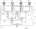
- FIG 3 it is shown a third order Virtual Microphone structure 15 3 , from an array of microphones 11 including four microphones M1, M2, M3, M4 which is characterized by a three levels L1, L2, L3 hierarchical virtual structure.
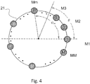
- UCAs are characterized by the spatial geometry depicted in figure 4 , where the microphones, M1, M2...Mm...MM, with M being the number of microphones, are uniformly displaced on a circumference at positions identified by angles ⁇ m , defining an array 21.
- ⁇ m is indicated the angle corresponding to the generic m-th microphone Mm.
- Virtual Microphone polar patterns have always a symmetric shape w.r.t. the z axis. If it is desired only one main lobe in the directivity pattern, for ULA arrays it must aim at 0 degrees or at 180 degrees only.
- polar patterns of Virtual Microphones obtained using differential UCA arrays are symmetric w.r.t. an axis, since a symmetry constraint is always applied in the derivation.
- the symmetry axis may be any of the M straight lines joining the center of the array and the M microphones.
- ⁇ m angle at which each of the M microphones is set
- DMA Differential Microphone Array
- the object of the embodiments described herein is to improve the potential of the methods according to the known art as set forth previously.
- Various embodiments may refer also to corresponding beamforming apparatuses as likewise to a computer program product that can be loaded into the memory of at least one computer (e.g., a terminal in a network) and comprises portions of software code suitable for carrying out the steps of the method when the program is run on at least one computer.
- the aforesaid computer program product is understood as being equivalent to a computer-readable medium containing instructions for control of the computer system so as to co-ordinate execution of the method according to the invention.
- Reference to "at least one computer” is meant to highlight the possibility of the present invention being implemented in a modular and/or distributed form. The claims form an integral part of the technical teachings provided herein in relation to the invention.
- a beamforming method employing a plurality of microphones arranged in arrays with respect to a reference point, including acquiring microphone signals issued by said plurality of microphones and combining said microphone signals to obtain Virtual Microphones, combining said microphone signals to obtain at least a pair of directional Virtual Microphone having respective signals determining respective patterns of radiation with a same origin corresponding to said reference point of the array and rotated at different pattern direction angles, defining a separation angle between them so that at least a circular sector is defined between said different pattern direction angles, said separation angle between the at least a pair of Virtual Microphones being lower than n/2, obtaining a signal of a sum Virtual Microphone, to which is associated a respective sum radiation pattern, associating a respective weight to the signals of said pair of directional Virtual Microphones, obtaining respective weighted signals and summing said weighted signals, computing said respective weights as a function of a determined pattern direction angle, of the pattern of radiation of said pair of directional Virtual Microphones and of the separation
- the method described further includes arranging said array as a Differential Microphone Array, in particular a Uniform Linear Array or a Uniform Circular Array.
- the method described further includes steering in said circular sector the pattern direction angle of said sum radiation pattern to obtain a sound source location estimate, obtaining said sound source location estimate selecting the direction on which the power of the signal of said sum Virtual Microphone is maximized.
- the method described further includes after combining said microphone signals to obtain Virtual Microphones, ranking the power of the signals of said Virtual Microphones, selecting a main circular sector defined by two adjacent virtual microphones on the basis of said ranking results, performing a continuous steering of the direction angles of said sum Virtual Microphone in said selected main circular sector to find said sound source location estimate.
- the method described further includes that said ranking includes obtaining a ranking list as a function of power of the virtual microphones starting from a virtual microphone which maximizes the power, said selecting a main circular sector includes selecting said virtual microphone which maximizes the power and, among the virtual microphones adjacent to said microphone, selecting the virtual microphone associated with the maximum power, defining the main circular sector as the sector comprised between the said virtual microphone which maximizes the power and said adjacent microphone.
- the method described further includes that the power is the Teager energy of the signal of the Virtual Microphone measured over a given time-frame of a given number of samples.
- a beamforming apparatus comprising a plurality of directional microphones arranged as an array, comprising at least a module configured to: acquire microphone signals issued by said plurality of microphones; combine said microphone signals to obtain Virtual Microphones, said module being further configured to providing said plurality of microphones as an array of microphones, combining said microphone signals to obtain at least a pair of directional Virtual Microphones having respective patterns of radiation with a same origin corresponding to said reference point of the array and rotated at different pattern direction angles so that at least a circular sector is defined between said different pattern direction angles; to obtain a sum signal of a sum Virtual Microphone, to which is associated a respective sum radiation pattern, associating a respective weight to the signals of said pair of directional Virtual Microphones, obtaining respective weighted signals and summing said weighted signals, computing said respective weights as a function of a determined pattern direction angle, of the pattern of radiation of said pair of directional Virtual Microphones and of the separation angle so that a main-lobe of said sum
- the described beamforming apparatus included in a source localization apparatus and is configured to steer in said circular sector the pattern direction angle of said sum radiation pattern to obtain a sound source location estimate, obtaining said sound source location estimate choosing the direction on which the power of the signal of said sum Virtual Microphone is maximized.
- references to "an embodiment” or “one embodiment” in the framework of the present description is meant to indicate that a particular configuration, structure, or characteristic described in relation to the embodiment is comprised in at least one embodiment.
- phrases such as “in an embodiment” or “in one embodiment”, that may be present in various points of the present description do not necessarily refer to the one and the same embodiment.
- particular conformations, structures, or characteristics can be combined appropriately in one or more embodiments.
- the method to perform beamforming basing on a plurality of microphones here described provides acquiring microphone signals from an array of microphones, preferably omni-directional microphones, signals issued by said plurality of microphones and combining said microphone signals to obtain Virtual Microphones, specifically to obtain at least a pair of directional Virtual Microphones having respective patterns of radiation with a same origin corresponding to said reference point of the array and rotated at different pattern direction angles so that at least a circular sector, preferably a circular sector of less than 90 degrees, is defined between said different pattern direction angles.
- Such beamforming method includes steering in such circular sector the pattern direction angle of said sum radiation pattern to obtain a sound source location estimate and obtaining said location estimate choosing the direction on which the power of the signals of said plurality of virtual microphones is maximized.
- the method here described reduces the problem of performing continuous steering from 0 to 2n (or the needed range of angles) to performing continuous steering in a discrete number of circular sectors. Therefore, it is provided building pairs of adjacent directive virtual microphones defining circular sectors and combining each pair in order to do continuous steering in each corresponding circular sector.
- figure 5 it is shown an example of geometry of array of omni-directional microphones which can be used to perform the beamforming method here described, using the DMA theory (ULA or UCA) adjacent directive Virtual Microphones defining circular sectors.
- the needed number of microphones is related to the desired resulting Virtual Microphones order.
- the reference point O where the Virtual Microphones are positioned, is the center of the circumference.
- CS a circular sector indicated with CS.
- FIG 7 it is shown an array of microphones 31" comprising eight microphones on an outer circumference OC and eight microphones on a concentric circumference CC, arranged on the respective circumferences at positions spaced by a separation angle p of n/4.
- FIG 8 it is shown an array of microphones 31"' comprising four microphones arranged on a circumference, M1 and M2 being separate of an angle p of ⁇ /8 and M3 and M4 being positioned simmetrically.
- M1 and M2 being separate of an angle p of ⁇ /8 and M3 and M4 being positioned simmetrically.
- FIG 9A are shown polar patterns of a pair of Virtual Microphones V1 and V2 obtained combining microphone signals of microphones in arrays, for instance in the array of figure 8 .
- Virtual Microphones V1 and V2 are identical and their polar patterns ⁇ V1 ( ⁇ ) and ⁇ V2 ( ⁇ ) have a symmetric shape.
- ⁇ SUM ⁇ ⁇ 1 ⁇ V 1 ⁇ + ⁇ 2 ⁇ V 2 ⁇
- ⁇ 1 is the weight (or gain) multiplying the first polar pattern ⁇ V1 ( ⁇ )
- ⁇ 2 is the weight multiplying the second polar pattern ⁇ V2 ( ⁇ ).
- ⁇ SUM ⁇ d ⁇ 2 ⁇ ⁇ V 1 ⁇ d + ⁇ V 1 ⁇ d ⁇ ⁇
- FIG 9B there are shown three different examples of sum pattern ⁇ SUM of a sum Virtual Microphone VSUM, identified by a respective sum signal V SUM , obtained from the pair of Virtual Microphones V1 and V2 of figure 9A , for three different values, 3p/4, p/2, p/3, of the desired direction ⁇ d .
- polar patterns as similar as possible are need for localization purposes, in order to compare the energy picked by the resulting Virtual Microphones aiming at different desired directions ⁇ d .
- the similarity property strongly depends on the separation angle p, which must be small enough to guarantee the desired level of similarity.
- the separation angle p between the Virtual Microphones V1 and V2 used to obtain the sum pattern ⁇ SUM ( ⁇ ) is lower than n/2.
- indexes which are calculated in order to objectify the degree of similarity.
- Two indexes I sum and I ⁇ measure the similarity in terms of area between the sum pattern ⁇ sum ( ⁇ ) and the pattern ⁇ V1 ( ⁇ ) of the Virtual Microphone of the pair determining the sum.
- I ⁇ is obtained, as described in the following, from a function ⁇ ( ⁇ ), which measures the similarity in terms of shape.
- I V 1 ⁇ ⁇ 0 2 ⁇ ⁇ V 1 ⁇ 2 2 d ⁇
- the shape-similarity index function ⁇ ( ⁇ ) is the difference between ⁇ sum ( ⁇ ) and a directive polar pattern with the same shape of ⁇ V1 ( ⁇ ) focusing to the main direction of ⁇ sum ( ⁇ ).
- figure 17 by way of example, it is shown the result of the computation of the area indexes in the case of a cardioids of the first order.
- the area is normalized.
- the shown curves are functions of the separation angle p.
- the ranges of values where the index I V (solid line) is circa I sum (dashed line) and I ⁇ (dotted line) is circa 0 correspond to values of separation p which grant high similarity.
- the area magnitudes of ⁇ V ( ⁇ ) and ⁇ sum ( ⁇ ) diverge as the area of ⁇ sum ( ⁇ ) grows exponentially.
- the separation angle p between the at least a pair of Virtual Microphones V1, V2 used to obtain the sum radiation pattern ⁇ SUM ( ⁇ ) is selected as lower than n/2 (circa 1,57 rad).
- FIG 10 11 and 12 are described examples of arrays of microphones generating a pair of Virtual Microphones of the first, second and third order respectively.
- each array geometry is described with respect to a fixed point in the space, called "reference point" O of the array.
- the resulting directional Virtual Microphone will be positioned in the reference point 0.
- the origin of the resulting polar pattern of the Virtual Microphone is the reference point itself. For instance, in the case of ULA and UCA the reference point is the midpoint of the array.
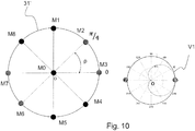
- FIG 10 it is shown an array 31' with microphones M0 in the center and microphones M1...M8 on a circumference, like one in depicted in figure 6 .
- Physical microphones M3 and M7 are used according to ULA theory to create a first order Virtual Microphone V1, which radiation pattern is also shown in figure 10 .
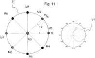
- FIG 11 it is shown the same array 31' of figure 10 where physical microphones M3, M0 and M7 are used to create a second order Virtual Microphone V1, which radiation pattern is also shown in figure 11 .
- FIG 12 it is shown the same array 31' of figure 10 , used however as an UCA like in figure 4 , where physical microphones M1, M2, M3, M4, M5, M6 and M7 are used to create a third order Virtual Microphone V1, which radiation pattern is also shown in figure 12 .
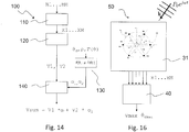
- the beamforming procedure described so far an embodiment 100 of which is indicated in the flow diagram shown in figure 14 , starting from a plurality of omni-directional microphones, M1...Mm, for instance M1...M4 in figure 8 , arranged as an array with respect to a reference point, such as ULA or UCA, where are acquired in a step 110 microphone signals X1...XM, issued by said plurality of microphones which are combined, in a step 120, to obtain at least a pair of Virtual Microphones, such as Virtual Microphones V1 and V2, having respective patterns of radiation with a same origin corresponding to the reference point O of the array and rotated at different pattern direction angles, defining a separation angle p, so that a circular sector CS of corresponding aperture is defined between said different pattern direction angles.
- M microphone signals X1...XM can be obtained N Virtual Microphones V1...VN, from which one or more pair of Virtual Microphones can be selected according to the rules and theories described with reference to previous figures 4-13 .
- such method of beamforming for performing a source localization uses the steering, through the operation 140 of modifying the weights, in the circular sectors of the pattern direction angle of said sum radiation pattern to obtain a sound source location estimate, obtaining said location estimate choosing the direction on which the power of the signals of said plurality of virtual microphones is maximized.
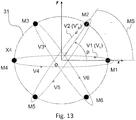
- FIG 13 A possible array geometry for doing steering employing first order Virtual Microphones in a ULA is depicted in figure 13 , which shows an array such as the array 31 of figure 5 .
- Six omni-directional microphones M1...M6 issue respective microphone signals which can be combined according to the described beamforming procedure 100 to obtain Virtual Microphones.
- FIG 15 shows a flow diagram representing an embodiment 200 of a source localization procedure, thus it is provided to acquire in a step 110 the analog microphone signals from the microphones M1...M6 through analog to digital conversion obtaining digital microphone signal X1...X6.
- Virtual Microphones in particular six Virtual Microphones V1...V6 are obtained, combining the signals X1...X6 using the linear DMA theory, as described with reference to figure 1 , i.e. applying a delay for instance to the signal X1 before summing the microphone signals, X1 and X4, which are signals of microphones placed at a given distance d, i.e. the diameter of the circumference of the array 31.
- Virtual Microphone V1 is obtained by combining digital signals X1 and X4
- Virtual Microphone V2 is obtained by combining digital signals X2 and X5
- Virtual Microphone V3 is obtained by combining digital signals X3 and X6.
- Virtual Microphone V4 is obtained by combining digital signals X4 and X1 (i.e. the combined signals are the same of Virtual Microphone V1, however the delay is applied to signal X4 this time), Virtual Microphone V5 is obtained by combining digital signals X5 and X2, Virtual Microphone V6 is obtained by combining digital signals X5 and X2.
- the described method starts from an array of microphones and builds at least a pair of Virtual Microphones by taking microphones of the whole array, this can also be regarded as taking the Virtual Microphones from one sub-array (es. ULA V2, from signals X2 and X5 in figure 13 ) in a greater array (array 31) and the other from another sub-array (es. ULA V5, from signals X5 and X2) in the greater array (31), it can be said that the beamforming method here described employs a plurality of microphones arranged in arrays with respect to a reference point, even if such arrays can be regarded as a single array, such as in the case of arrays 21, 31, 31', 31", 31". The number of arrays to be considered depends on the level of abstraction applied.
- a step 230 it is performed a Main Circular Sector Selection considering only the signals of the Virtual Microphones adjacent to the marked first Virtual Microphone V k , in the example V2 and V6, and selecting the adjacent Virtual Microphone which has the greater energy between the adjacent Virtual Microphones, i.e. it is in an upper position in the energy ranking list, and indicating the corresponding Virtual Microphone as second marked Virtual Microphone Vk; in the example of figure 13 V2 is chosen as second marked Virtual Microphone Vk.
- a Main Circular Sector MS is defined as the circular sector comprised between the first and second marked Virtual Microphone, Vk and Vk.
- the direction of the second marked virtual signal V k ⁇ defines a second marked angle ⁇ p , which is also supplied as output at the step 230.
- a sub-procedure 240 it is then performed a continuous steering in the Main Circular Sector selected at step 230 to perform source localization, applying the steering steps of the beamforming method described previously, using the first and second marked Virtual Microphone, Vk and Vk as the pair of Virtual Microphones input to step 140.
- the step of computing 130 said weights ⁇ 1 , ⁇ 2 as a function of a determined or desired pattern direction angle ⁇ d , which however in this case is a maximum search angle ⁇ bis direction, i.e. the new direction along which the maximum is searched, calculated by a maximum energy finding procedure 245, and of the separation angle p so that a mainlobe of said sum radiation pattern ⁇ SUM ( ⁇ ) is steered within the circular sector, in this case the Main Circular Sector MS, to point in the direction of said desired angle ⁇ d , i.e. maximum search angle ⁇ bis .
- a maximum search angle ⁇ bis direction i.e. the new direction along which the maximum is searched
- the step 140 is evaluated in a step 250 the power of the sum signal V SUM in the desired direction, in particular is evaluated the Teager Energy E T of the sum signal V SUM .
- a step 260 is evaluated if the Teager Energy E T of the sum signal V SUM is the maximum energy in the Main Sector MS.
- this evaluation step 260 is preferably part of an iterative procedure, and in this case the resolution of the iterative procedure is controlled by a resolution parameter RES supplied to the step 260 for the evaluation.
- the location estimate i.e. the maximizing direction ⁇ dmax which corresponds to the desired direction
- the maximizing direction ⁇ dmax is the source location estimate in radians.
- the evaluation step 260 supplies the corresponding signal V max of the sum radiation pattern ⁇ SUM ( ⁇ ) pointed in the maximizing direction ⁇ dmax .
- a new maximum search angle direction ⁇ bis is selected in a step 270 and in the step 130 the weights ⁇ 1 ⁇ 2 supplied to step 140 to steer the sum pattern ⁇ SUM ( ⁇ ) are computed on the basis of such new maximum search angle ⁇ bis .
- a first marked angle ⁇ max is supplied to the step 270 which determines the new maximum search angle direction ⁇ bis , which corresponds to the direction of the first marked Virtual Microphone, while a second marked angle ⁇ p , corresponding to the direction of the second marked Virtual Microphone Vk is passed from step 230 to the same step 270.
- This is performed so that the step 270 can choose the new maximum search direction ⁇ bis , i.e. the desired direction ⁇ d , to which point the sum radiation pattern through steps 130 and 140, within the Main Circular sector MS defined between the first marked angle ⁇ max and the second marked angle ⁇ p .
- the localization procedure 200 is a variant of the beamforming procedure 100, which adds a ranking procedure (steps 210-230), after steps 110-120 forming pairs of Virtual Microphones from the microphones signal, to identify a pair of Virtual Microphones defining a Main Sector MS, which has the maximum probability of including the maximizing direction ⁇ dmax .
- This main sector MS corresponds to the Circular Sector CS of the beamforming procedure 100, thus it is supplied to the beamforming steps 130-140, which determine a sum radiation pattern steerable within said Circular Sector CS, i.e. Main Sector NS.
- These steps 130-140 are performed under the control of a maximum energy finding procedure 245 including the steps 250-270.
- V max in the pseudocode is in general the output signal, which varies in time, of the beamformer driven by the localization procedure.
- E Tmax is a variable indicating the maximum value taken by the Teager energy E T .
- ⁇ bis the maximum search angle, is the new desired direction at a given iteration step j of the procedure 240, i.e. of the maximum energy finding procedure 245 which then reiterates steps 130 and 140.
- the weighted sum Virtual Microphone V SUM is obtained from the two marked Virtual Microphones pointing in that direction, i.e. it is performed the steering in the Main circular Sector MS according the beamforming method described above. Then the energy of the weighted Virtual Microphone V SUM in that direction is evaluated, and if greater than the maximum energy E Tmax , the corresponding direction is selected as new maximizing direction ⁇ max .
- a new circular sector which is a subsector of the main sector, defined between the new maximizing direction ⁇ max and the previous maximizing direction, which becomes the second boundary direction ⁇ p , is selected and the procedure including steering the sum pattern in a direction inside the subsector, in particular in the middle of the subsector, and evaluating the energy is repeated. If the energy of the weighted Virtual Microphone V SUM is minor than the maximum energy E Tmax, , the remaining circular subsector of the two subsector obtained by setting the maximum search angle or steering direction angle ⁇ bis , is chosen to repeat the procedure, i.e. the sector having as second boundary direction ⁇ p equal to the current steering direction ⁇ bis , while the value of ⁇ max is mantained The procedure is repeated for a given number of times.
- RES is a positive integer. Higher is the predefined resolution RES, higher will be the direction resolution.
- the resolution RES corresponds for instance to the number of iterations to be performed.
- the third step of steering in the Main Circular Sector and the search of the direction maximizing the Teager Energy can of course be performed also using different maximum search algorithms.
- a remarkable property of the presented source-localization method is that in principle any steering resolution can be chosen.
- Figure 16 shows schematically an apparatus 50 implementing the method here described.
- an array 31 which is the one shown in Figure 5 , with six physical microphones M1...M6.
- it can be any set of directional microphones arranged as an array with respect to a reference point and at a distance d one with respect the other, the distance d being negligible than the wavelength of the sound wave of pressure amplitude P0 and frequency ⁇ incoming along a propagation vector k to be detected, as also described with reference to figure 1 .
- it is a DMA array, in particular a DMA-ULA or DMA-UCA.
- Such an array 31 supplies the signals of the microphones, X1...XM, which are in the example analog signals, to a processing module 40.
- Such processing module 40 is preferably a microprocessor or microcontroller configured to implement the operations of beamforming method 100 or the localization method 200, in particular building the Virtual Microphones according to the order required, obtaining the sum Virtual Microphone to be steered, and performing the steering, in particular with the aim of localizing the direction of arrival of the sound wave P0.
- the processing module 40 can be alternatively a DSP or any other processing module suitable to implement the operations of the methods 100 and/or 200.
- the processing module can be included in one or more computer as well.
- the described solution allows to build arbitrary-order-DMA-based parametric sound source localization systems which allow doing steering in a continuous fashion in all directions.
- the described beamforming solution allows to build polar patterns of any order which are similar to each other, aiming at arbitrary directions, this being in particular highly desirable for localization purposes.
- the direction of the resulting beam can be easily adjusted simply changing the constrained weights of the polar pattern addends: only one tuning parameter is necessary.
- the described solution for what regards localization systems has the following desirable features: beamforming and source localization are applicable simultaneously; the localization accuracy is theoretically arbitrarily selectable; localization resolution is tunable in a parametric fashion.
- the DMA-based beamformer which can be steered in a continuous fashion substantially resolves the problems of computational complexity since the beams are characterized by a 2D shape: in fact during an iterative localization procedure, the system may be tuned in order to find the desired trade-off between accuracy and resource consumption. This means that the first iterations give already a right estimate of the direction of arrival, although characterized by low resolution.
- the invention is particularly suitable, but not limited to, systems based on Differential Microphone Array (DMA) techniques.
- DMA Differential Microphone Array
- Such techniques are applicable to arrays where the distances between microphones are negligible w.r.t. the wavelength of the sound waves of interest. Due to their small dimensions MEMS microphones are particularly suitable for these applications.
Landscapes
- Health & Medical Sciences (AREA)
- Otolaryngology (AREA)
- Physics & Mathematics (AREA)
- Engineering & Computer Science (AREA)
- Acoustics & Sound (AREA)
- Signal Processing (AREA)
- General Health & Medical Sciences (AREA)
- Circuit For Audible Band Transducer (AREA)
- Obtaining Desirable Characteristics In Audible-Bandwidth Transducers (AREA)
- Mounting, Exchange, And Manufacturing Of Dies (AREA)
- Laser Beam Processing (AREA)
- Measurement Of Velocity Or Position Using Acoustic Or Ultrasonic Waves (AREA)
Abstract
Description
- The present description relates to beamforming based on a plurality of microphones arranged in an array or arrays with respect to a reference point, including acquiring microphone signals issued by said plurality of microphones.
- Such techniques are preferably applied to sound source localization.
- It is very well known to use arrays of microphones to perform sound, or acoustic, source localization, i.e., locating a sound source given measurements of the sound field, which in particular are obtained by such microphones.
- It is also known to use signal processing modules such as DSP (Digital Signal Processing) modules to process the signals from each of the individual microphone array elements to create one or more Virtual Microphones (VMIC).
- Virtual Microphones (VMIC) are therefore a combination of filtered versions of the signals picked by an array of microphones arranged in a particular spatial geometry.
- Virtual Microphones may be obtained in a recursive fashion using combinations of other Virtual Microphones organized in virtual arrays. Therefore, in general, a Virtual Microphone is characterized by a hierarchical virtual structure with a number L greater equal than one of layers: the first layer combines physical microphone signals generating an array of Virtual Microphones and any higher layer combines Virtual Microphone signals forming further arrays of Virtual Microphones.
- For what concerns the Virtual Microphone position, considering an array of virtual or physical microphones, the array is geometrically described with respect to a fixed reference point in the physical space: the Virtual Microphone resulting from the combination of microphone signals of this array is virtually positioned in the same fixed reference point of the array.
- For what regards a general polar pattern function, a Virtual Microphone is characterized by an omnidirectional or directive polar pattern or directivity pattern.
- An N-th order frequency-independent microphone directivity pattern Γ(θ) is defined as:

- It is convenient to set such coefficients as follows:


- In the following it will be referred to a Virtual Microphone characterized by a polar pattern of the N-th order as a N-th order Virtual Microphone.
- Directive Virtual Microphones are known. Known DSP techniques allow building directive Virtual Microphones of any order starting from arrays of (physical) omnidirectional microphones. Two broad classes of such DSP techniques are known as:
- filter and sum techniques;
- Differential Microphone Array techniques.
- Differential Microphone Arrays (DMAs) are built subtracting each other the delayed microphone signals of the array.
- The delays can be tuned in order to obtain a Virtual Microphone with the desired polar pattern shape, according to well known design principles.
- The two broadest classes of DMAs with uniform geometries are:
- Uniform Linear Arrays (ULA);
- Uniform Circular Arrays (UCA).
- Also Linear DMAs with non uniform geometries have been
discussed. - In a First Order Differential ULA, shown schematically in
Figure 1 , anarray 11 is constituted of two physical omni-directional microphones M1, M2, supplying a pair of microphone signals (m-d/2, md/2), positioned at a distance d one with respect to the other. A reference point O of the array is placed at the origin of the z-y Cartesian diagram. A sound wave of pressure amplitude P0 and frequency ω propagates along a propagation vector k in direction of such array. With θ is indicated the direction angle, i.e. the angle between the propagation vector k and the horizontal axis z of the array of microphones. The pair of microphone signals (m-d/2, m+d/2) is subtracted in asubtraction node 13, after that to one of the two signals is applied in a delay module 12 a delay τ. Varying τ the designer can adjust the resulting polar pattern shape. - The
delay module 12 andsubtraction node 13 identify aVirtual microphone 15 structure, having as input the pair of microphone signals (m-d/2, md/2) and as output a first order Virtual Microphone is obtained generating a virtual Microphone signal V(t), in particular here the resulting first order Virtual Microphone signal V1(t) is expressed as:
- A
filter 14, Hc(ω), is provided at the output of thevirtual microphone structure 15 to operate on the Virtual Microphone signal V1(t), which is a correction filter (i.e. low pass filter), applied to the Virtual Microphone V1(t) signal in order to compensate for the frequency dependent effect of the signal subtraction. - The distance d between the microphones of the
array 11 must be small enough w.r.t. the wavelength of the signal so that it can be considered negligible. - The shape of the polar pattern will be almost constant over a broad range of frequencies.
- The polar pattern coefficient a1 is related to the delay τ by the formula:

- In
Figure 2 it is shown a structure producing as a result a second order Virtual Microphone. As it can be seen the structure ofFigure 1 of first order Virtual Microphone with a pair of microphones, which signals are sent to a difference module, is replicated. Three microphones M1, M2, M3 define two pairs of microphones at level L1 with two first order Virtual Microphones 151, including a delay and a difference module, like inFigure 1 , while at level L2 another corresponding Virtual Microphones 152, collects the output of such first order Virtual Microphones 151 operating the same delay and difference operations, although the delay value can be different. The chain is concluded, like inFigure 1 , by thefilter 14. As mentioned, a first delay τ1, associated to the delay module of level L1, and a second delay τ2, associated to the delay module of level L2, can be tuned by the designer in order to obtain a Virtual Microphone with arbitrary directive polar pattern of the second order
Setting the polar pattern coefficients a1= η1 + η2 - 2η1η2 and a2 = η1η2 it is obtained for the delays:


- In
figure 3 it is shown a third orderVirtual Microphone structure 153, from an array ofmicrophones 11 including four microphones M1, M2, M3, M4 which is characterized by a three levels L1, L2, L3 hierarchical virtual structure. - With reference to
figure 4 , it is possible to derive N-th order Virtual Microphones also with the alternative recently developed class of Differential Uniform Circular Arrays (UCA). UCAs are characterized by the spatial geometry depicted infigure 4 , where the microphones, M1, M2...Mm...MM, with M being the number of microphones, are uniformly displaced on a circumference at positions identified by angles ψm, defining anarray 21. In particular, infigure 4 with ψm is indicated the angle corresponding to the generic m-th microphone Mm. For deeper understanding of UCAs it is here made reference to the book "Design of Circular Differential Microphone Arrays", Benesty, Jacob, Jingdong, Chen,Cohen, Israel, Springer Verlag, 2015. - It is here underlined the fact that, indicating with N the number of Virtual Microphones obtained by M physical microphones, the maximum polar pattern order obtainable with an UCA is Nmax = M/2, which means that with M = 2 or M = 3 microphones it can be derived up to a first order Virtual Microphone; with M = 4 or M = 5 microphones it can be derived up to a second order Virtual Microphone; with M = 6 or M = 7 microphones it can be derived up to a thirst order Virtual Microphone; and so on.
- The higher the number M of microphones, the more robust is the DMA array. It is possible doing steering in all the M directions identified by the angle ψm.
- Virtual Microphone polar patterns have always a symmetric shape w.r.t. the z axis. If it is desired only one main lobe in the directivity pattern, for ULA arrays it must aim at 0 degrees or at 180 degrees only.
- Also polar patterns of Virtual Microphones obtained using differential UCA arrays are symmetric w.r.t. an axis, since a symmetry constraint is always applied in the derivation.
- The symmetry axis may be any of the M straight lines joining the center of the array and the M microphones. In general it is not possible to design the Virtual Microphone polar pattern with the main lobe aiming at a direction different from angle ψm at which each of the M microphones is set, with 1 ≤ m ≤ M. As explained in the above mentioned publication by Benesty et al., applying super-directive beamforming to UCA and getting rid of the symmetry constraint it is possible to design Virtual Microphones aiming at arbitrary directions, but the shape of the resulting polar pattern strongly depends on the main lobe direction. All these considerations apply in relation to a two-dimensional array.
- Although arbitrary order Differential Microphone Array (DMA) based systems with Virtual Microphones steerable in arbitrary directions would be highly desirable for localization purposes, however using known DMAs, doing steering in arbitrary directions with arbitrary order Virtual Microphones characterized by polar patterns with shapes comparable to each other is not possible; so continuous steering is infeasible. Doing steering with identical polar patterns of any order is possible only for a discrete set of directions:
- 0 degrees and 180 degrees for ULAs;
- angle ψm with 1 ≤ m ≤ M for UCAs.
- The object of the embodiments described herein is to improve the potential of the methods according to the known art as set forth previously.
- Various embodiments achieve the above object thanks to a method having the characteristics specified in the ensuing claims.
- Various embodiments may refer also to corresponding beamforming apparatuses as likewise to a computer program product that can be loaded into the memory of at least one computer (e.g., a terminal in a network) and comprises portions of software code suitable for carrying out the steps of the method when the program is run on at least one computer. As used herein, the aforesaid computer program product is understood as being equivalent to a computer-readable medium containing instructions for control of the computer system so as to co-ordinate execution of the method according to the invention. Reference to "at least one computer" is meant to highlight the possibility of the present invention being implemented in a modular and/or distributed form. The claims form an integral part of the technical teachings provided herein in relation to the invention.
- In various embodiments it is described a beamforming method employing a plurality of microphones arranged in arrays with respect to a reference point, including
acquiring microphone signals issued by said plurality of microphones and combining said microphone signals to obtain Virtual Microphones,
combining said microphone signals to obtain at least a pair of directional Virtual Microphone having respective signals determining respective patterns of radiation with a same origin corresponding to said reference point of the array and rotated at different pattern direction angles, defining a separation angle between them so that at least a circular sector is defined between said different pattern direction angles, said separation angle between the at least a pair of Virtual Microphones being lower than n/2,
obtaining a signal of a sum Virtual Microphone, to which is associated a respective sum radiation pattern, associating a respective weight to the signals of said pair of directional Virtual Microphones, obtaining respective weighted signals and summing said weighted signals, computing said respective weights as a function of a determined pattern direction angle, of the pattern of radiation of said pair of directional Virtual Microphones and of the separation angle so that a main-lobe of said sum radiation pattern is steered within said circular sector to point in the direction of said determined pattern direction angle. - In various embodiments, the method described further includes arranging said array as a Differential Microphone Array, in particular a Uniform Linear Array or a Uniform Circular Array.
- In various embodiments, the method described further includes steering in said circular sector the pattern direction angle of said sum radiation pattern to obtain a sound source location estimate,
obtaining said sound source location estimate selecting the direction on which the power of the signal of said sum Virtual Microphone is maximized. - In various embodiments, the method described further includes after combining said microphone signals to obtain Virtual Microphones, ranking the power of the signals of said Virtual Microphones, selecting a main circular sector defined by two adjacent virtual microphones on the basis of said ranking results, performing a continuous steering of the direction angles of said sum Virtual Microphone in said selected main circular sector to find said sound source location estimate.
- In various embodiments, the method described further includes that said ranking includes obtaining a ranking list as a function of power of the virtual microphones starting from a virtual microphone which maximizes the power, said selecting a main circular sector includes selecting said virtual microphone which maximizes the power and, among the virtual microphones adjacent to said microphone, selecting the virtual microphone associated with the maximum power, defining the main circular sector as the sector comprised between the said virtual microphone which maximizes the power and said adjacent microphone.
- In various embodiments, the method described further includes that the power is the Teager energy of the signal of the Virtual Microphone measured over a given time-frame of a given number of samples.
- In various embodiment it is described a beamforming apparatus comprising a plurality of directional microphones arranged as an array, comprising at least a module configured to: acquire microphone signals issued by said plurality of microphones; combine said microphone signals to obtain Virtual Microphones, said module being further configured to providing said plurality of microphones as an array of microphones, combining said microphone signals to obtain at least a pair of directional Virtual Microphones having respective patterns of radiation with a same origin corresponding to said reference point of the array and rotated at different pattern direction angles so that at least a circular sector is defined between said different pattern direction angles; to obtain a sum signal of a sum Virtual Microphone, to which is associated a respective sum radiation pattern, associating a respective weight to the signals of said pair of directional Virtual Microphones, obtaining respective weighted signals and summing said weighted signals, computing said respective weights as a function of a determined pattern direction angle, of the pattern of radiation of said pair of directional Virtual Microphones and of the separation angle so that a main-lobe of said sum radiation pattern is steered within said circular sector to point in the direction of said determined pattern direction angle.
- In variant embodiments the described beamforming apparatus included in a source localization apparatus and is configured to steer in said circular sector the pattern direction angle of said sum radiation pattern to obtain a sound source location estimate, obtaining said sound source location estimate choosing the direction on which the power of the signal of said sum Virtual Microphone is maximized.
- The solution will now be described purely by way of a non-limiting example with reference to the annexed drawings, in which:
-
Figures 1-4 have been already described in the foregoing; -
Figure 5 shows schematically an example of array of microphones which can be used to perform the method here described; -
Figures 6-8 shows schematically further examples of array of microphones which can be used to perform the method here described; -
Figure 9A shows polar patterns of Virtual Microphones obtained combining microphone signals of microphone arrays according to the method here described; -
Figure 9B show examples of sum polar patterns of a sum Virtual microphone obtained from the polar patterns of Virtual Microphones ofFigure 9A ; -
Figures 10 ,11 and12 shown examples of polar patterns of Virtual Microphones of the first, second and third order obtained according to the method here described; -
Figure 13 shows a further schematic representation of the array ofFigure 5 ; -
Figure 14 shows a flow diagram representing operations of the method here described; -
Figure 15 shows a flow diagram representing a variant embodiment of the method here described- -
Figure 16 shows schematically an apparatus implementing the method here described; -
Figure 17 represent a diagram showing similarity indexes of Virtual Microphone. - The ensuing description illustrates various specific details aimed at an in-depth understanding of the embodiments. The embodiments may be implemented without one or more of the specific details, or with other methods, components, materials, etc. In other cases, known structures, materials, or operations are not illustrated or described in detail so that various aspects of the embodiments will not be obscured.
- Reference to "an embodiment" or "one embodiment" in the framework of the present description is meant to indicate that a particular configuration, structure, or characteristic described in relation to the embodiment is comprised in at least one embodiment. Likewise, phrases such as "in an embodiment" or "in one embodiment", that may be present in various points of the present description, do not necessarily refer to the one and the same embodiment. Furthermore, particular conformations, structures, or characteristics can be combined appropriately in one or more embodiments.
- The references used herein are intended merely for convenience and hence do not define the sphere of protection or the scope of the embodiments.
- The method to perform beamforming basing on a plurality of microphones here described provides acquiring microphone signals from an array of microphones, preferably omni-directional microphones, signals issued by said plurality of microphones and combining said microphone signals to obtain Virtual Microphones, specifically to obtain at least a pair of directional Virtual Microphones having respective patterns of radiation with a same origin corresponding to said reference point of the array and rotated at different pattern direction angles so that at least a circular sector, preferably a circular sector of less than 90 degrees, is defined between said different pattern direction angles. Then it is provided to associate a different weight to said respective patterns of radiation, obtaining a sum radiation pattern, which main-lobe is orientated according a given pattern direction angle depending from such weights, such sum radiation pattern being associated to a respective sum Virtual Microphone summing one to the other the radiation patterns of the weighted pair, modifying said weights associated to the patterns of radiations to steer in said circular sector the pattern direction angle of said sum radiation pattern to reach a desired direction angle.
- Further a variant of such beamforming method to perform source localization is here described. Such beamforming method includes steering in such circular sector the pattern direction angle of said sum radiation pattern to obtain a sound source location estimate and obtaining said location estimate choosing the direction on which the power of the signals of said plurality of virtual microphones is maximized.
- This corresponds to steer a Virtual Microphone beam in each direction in a continuous fashion, using non uniform weight concentric arrays of microphones beamforming on pairs of said microphone signals to obtain a plurality of virtual microphones having the same position in space, with different angles of rotation and non uniform amplitude gains.
- The method here described reduces the problem of performing continuous steering from 0 to 2n (or the needed range of angles) to performing continuous steering in a discrete number of circular sectors. Therefore, it is provided building pairs of adjacent directive virtual microphones defining circular sectors and combining each pair in order to do continuous steering in each corresponding circular sector.
- In
figure 5 it is shown an example of geometry of array of omni-directional microphones which can be used to perform the beamforming method here described, using the DMA theory (ULA or UCA) adjacent directive Virtual Microphones defining circular sectors. The needed number of microphones is related to the desired resulting Virtual Microphones order. - In
figure 5 it is shown an array ofmicrophones 31 comprising a number M=6 of microphones M1...M6 arranged on a circumference at positions spaced of a separation angle p of n/3. The reference point O, where the Virtual Microphones are positioned, is the center of the circumference. Between microphones M1 and M2 is defined a circular sector indicated with CS. - With the geometry of the
array 31 it is possible to build six directive first order Virtual Microphones using DMA-ULA theory; six directive (first, second or) third order Virtual Microphones using DMA-UCA theory; defining circular sectors CS with an aperture angle, which corresponds to the separation angle between physical microphones, p = n/3. - In
figure 6 it is shown an array of omni-directional microphones 31' comprising a number M=9 of microphones M1...M9, eight of such microphones being arranged on a circumference at positions spaced by a separation angle p of n/4 and one microphone M9 placed in the center of the circumference, which represents also the reference point O, Between microphones M1 and M2 is indicated a circular sector CS. - With the geometry of array 31' it is possible to build eight directive (first or) second order Virtual Microphones using DMA-ULA theory; eight directive first, second or third order Virtual Microphones using DMA-UCA theory; defining circular sectors of an aperture angle p = n/4.
- In
figure 7 it is shown an array ofmicrophones 31" comprising eight microphones on an outer circumference OC and eight microphones on a concentric circumference CC, arranged on the respective circumferences at positions spaced by a separation angle p of n/4. - With the geometry of
array 31" it is possible to build eight directive (first or) second order Virtual Microphones using DMA-ULA theory; eight directive first, second or third order Virtual Microphones using DMA-UCA theory; defining circular sectors CS of an aperture angle p = n/4. - In
figure 8 it is shown an array ofmicrophones 31"' comprising four microphones arranged on a circumference, M1 and M2 being separate of an angle p of π/8 and M3 and M4 being positioned simmetrically. With the geometry of array 31'" it is possible to build four directive (first or) second order Virtual Microphones using DMA-ULA theory defining circular sectors CS of an aperture angle p = n/8. - Therefore it is possible to provide a variety of geometries of microphone arrays like the ones shown in
Figures 5-8 which are Non Uniform Weight Concentric Array of physical microphones, with which can be performed beamforming to obtain Virtual Microphones according either to DMA ULA or UCA theory, such Virtual Microphones being located in the center of the circumferences, i.e in thereference points 0, and their directions separated of a given angle p, defining circular sectors CS between adjacent pattern directions of Virtual Microphones. - Now, a method for beamforming based on a plurality of microphones arranged as an array with respect to a reference point, the array being for instance either one of those described with reference to
figures 5-8 , will be described. - In
figure 9A are shown polar patterns of a pair of Virtual Microphones V1 and V2 obtained combining microphone signals of microphones in arrays, for instance in the array offigure 8 . Considering the circular sector comprised between the two axes identified by direction angles θ=0 and θ=ρ and considering two directional Virtual Microphones V1 and V2, which are positioned in the same point in the space and focused to the two different directions θ=0 and θ=ρ, the main-lobe directions, calculated as angle with respect to the x axis, of the corresponding polar patterns ΓV1(θ) and ΓV2(θ) are θ=0 and θ=ρ respectively. - It is assumed here that Virtual Microphones V1 and V2 are identical and their polar patterns ΓV1(θ) and ΓV2(θ) have a symmetric shape. To this regard in
figure 9A are shown two pattern diagrams representing first order cardioids as an example of two concentric identical Virtual Microphones with desired direction angle θd=0 and desired direction angle θd=ρ, where p=n/3. However the considerations that follows are valid for two Virtual Microphones V1 and V2 of arbitrary order and arbitrary shape. - In order to perform continuous steering in the defined circular sector of a Virtual Microphone polar pattern, it is obtained a weighted sum of the polar patterns of the pair of Virtual Microphones V1 and V2. The weighted sum of the polar patterns ΓV1(θ) and ΓV2(θ) of the two Virtual Microphones V1 and V2 can be written as:

- Equivalently using the Pattern Multiplication rule:

- As a consequence it is also possible to write:

- Then, after obtaining the weighted sum of the polar patterns, still to perform steering in arbitrary directions in a circular sector it is considered the main-lobe of the weighted sum pattern ΓSUM(θ) to the generic predetermined desired direction θd, with 0≤θd≤ρ.
- It is set a linear constraint α1=βα2, with β a constraint parameter, and it is expressed also the desired direction θd in terms of the same constraint parameter β:

- This means for instance that if the constraint parameter β is equal to 1 the desired direction θd is p/2.
- Therefore, given the desired direction θd, the constraint parameter β is fixed at the value:

- Consequently, it is possible to adjust the gains for matching the desired direction θd according to the following formula:

- Then it is normalized the polar pattern imposing ΓSUM = 1:


- Then:

- In
figure 9B there are shown three different examples of sum pattern ΓSUM of a sum Virtual Microphone VSUM, identified by a respective sum signal VSUM, obtained from the pair of Virtual Microphones V1 and V2 offigure 9A , for three different values, 3p/4, p/2, p/3, of the desired direction θd. - It can be seen from
figures 9A and 9B that the pattern ΓV1(θ) and sum pattern ΓSUM(θ) represented in the previous examples are different, but visibly quite similar in terms of shape and area. - As mentioned, polar patterns as similar as possible are need for localization purposes, in order to compare the energy picked by the resulting Virtual Microphones aiming at different desired directions θd.
- The similarity property strongly depends on the separation angle p, which must be small enough to guarantee the desired level of similarity. Preferably the separation angle p between the Virtual Microphones V1 and V2 used to obtain the sum pattern ΓSUM(θ) is lower than n/2.
- In
figure 17 are shown indexes which are calculated in order to objectify the degree of similarity. Two indexes Isum and IΘ measure the similarity in terms of area between the sum pattern Γsum (θ) and the pattern ΓV1(θ) of the Virtual Microphone of the pair determining the sum. IΘ is obtained, as described in the following, from a function Θ(θ), which measures the similarity in terms of shape. Isum and IΘ are functions of the ratio IV1, between the area of ΓV1(θ) and the area of an omnidirectional polar pattern, which is πR2, with radius R=1
- The first index Isum is simply the area of Γsum (θ) normalized w.r.t. the omnidirectional polar pattern:

- High area-similarity between Γsum(θ) and ΓV1(θ) requires Isum-IV1 to be low.
- The shape-similarity index function Θ(θ) is the difference between Γsum(θ) and a directive polar pattern with the same shape of ΓV1(θ) focusing to the main direction of Γsum (θ). Θ(θ) is mathematically defined as:


- High area-similarity between Γsum(θ) and ΓV1(θ) requires IΘ to be low.
- In
figure 17 , by way of example, it is shown the result of the computation of the area indexes in the case of a cardioids of the first order. The area is normalized. The shown curves are functions of the separation angle p. Qualitatively it is possible to say that the ranges of values where the index IV (solid line) is circa Isum (dashed line) and IΘ (dotted line) is circa 0 correspond to values of separation p which grant high similarity. For higher values of separation angle p the area magnitudes of ΓV(θ) and Γsum(θ) diverge as the area of Γsum(θ) grows exponentially. For this reason the separation angle p between the at least a pair of Virtual Microphones V1, V2 used to obtain the sum radiation pattern ΓSUM(θ) is selected as lower than n/2 (circa 1,57 rad). - Limiting the separation angle gives also advantages in terms of speed of computations in applications, such as the source localization described in the following. With suitable angle of separation p, the shape-similarity is so high that, for application purposes, it is possible to assume also sum pattern ΓSUM(θ) being symmetric with respect to its central axis as α1ΓV1.
- In
figure 10 ,11 and12 are described examples of arrays of microphones generating a pair of Virtual Microphones of the first, second and third order respectively. - As already mentioned, each array geometry is described with respect to a fixed point in the space, called "reference point" O of the array. The resulting directional Virtual Microphone will be positioned in the
reference point 0. The origin of the resulting polar pattern of the Virtual Microphone is the reference point itself. For instance, in the case of ULA and UCA the reference point is the midpoint of the array. - In
figure 10 it is shown an array 31' with microphones M0 in the center and microphones M1...M8 on a circumference, like one in depicted infigure 6 . Physical microphones M3 and M7 are used according to ULA theory to create a first order Virtual Microphone V1, which radiation pattern is also shown infigure 10 . Such radiation pattern V1 points to θ=0 rad. Physical microphones M2 and M6, are used to create a second first order Virtual Microphone V2, which radiation pattern points to θ=π/4 rad. It is indicated the circular sector CS which is defined by the chosen Virtual Microphones. Using different physical microphones results in addressing different sectors. - In
figure 11 it is shown the same array 31' offigure 10 where physical microphones M3, M0 and M7 are used to create a second order Virtual Microphone V1, which radiation pattern is also shown infigure 11 . Such radiation pattern V1 points to θ=0 rad. Physical microphones M2, M0 and M6, are used to create a second first order Virtual Microphone V2, which radiation pattern points to θ=π/4 rad. - In
figure 12 it is shown the same array 31' offigure 10 , used however as an UCA like infigure 4 , where physical microphones M1, M2, M3, M4, M5, M6 and M7 are used to create a third order Virtual Microphone V1, which radiation pattern is also shown infigure 12 . Such radiation pattern V1 points to θ=0 rad. Physical microphones M1, M2, M3, M4, M5, M6 and M7, are also used to create a second first order Virtual Microphone V2 which radiation pattern points to θ=π/4 rad. - Thus, the above operations are applicable to arbitrary order Virtual Microphones, considering the example of arbitrary order cardioids. The general formula describing an N-th order cardioid polar pattern ΓC N(θ), known in the literature, is the following:

- The corresponding polar pattern coefficients ai are:
- First Order Case: a1 = 0,5;
- Second Order Case: a1 = 0,5 a2 = 0,25;
- Third Order Case: a1 = 0,375 a2 = 0,375 a3 = 0,125.
- Thus, the beamforming procedure described so far, an
embodiment 100 of which is indicated in the flow diagram shown infigure 14 , starting from a plurality of omni-directional microphones, M1...Mm, for instance M1...M4 infigure 8 , arranged as an array with respect to a reference point, such as ULA or UCA, where are acquired in astep 110 microphone signals X1...XM, issued by said plurality of microphones which are combined, in astep 120, to obtain at least a pair of Virtual Microphones, such as Virtual Microphones V1 and V2, having respective patterns of radiation with a same origin corresponding to the reference point O of the array and rotated at different pattern direction angles, defining a separation angle p, so that a circular sector CS of corresponding aperture is defined between said different pattern direction angles. In general from M microphone signals X1...XM can be obtained N Virtual Microphones V1...VN, from which one or more pair of Virtual Microphones can be selected according to the rules and theories described with reference to previousfigures 4-13 . - In a
step 130, given the desired direction θd, the separation angle p, and the polar pattern of radiation of the Virtual Microphones, which as seen above can be represented by the polar pattern ΓV1, the weights α1, α2 are obtained, for instance using the relationship (1) and (2), applied in θd, p and ΓV1:


- This are the weights required to point the weighted sum ΓSUM(θ) of the polar patterns of the pair of Virtual Microphones V1 and V2 in the desired direction ϑd , given a determined separation angle p.
- Thus, the
step 130 provides computing the weights α1, α2 as a function of a determined pattern direction angle θd, of the patterns of radiation, ΓV=ΓV1=ΓV2 since the pattern are identical, of the pair of directional Virtual Microphones V1, V2 and of the separation angle p so that a main-lobe of said sum radiation pattern ΓSUM(θ) is steered within said circular sector CS to point in the direction of said determined pattern direction angle θd. - In step 140 a sum signal VSUM=α1V1 + α2V2 is obtained, which is the signal observed by a virtual microphone pointing in the desired direction ϑd and which radiation pattern is ΓSUM(θ)=α1ΓV1(θ) + α2ΓV2(θ), applying the weight computed at
step 130, therefore the sum Virtual Microphone signal VSUM (θ) determines a radiation pattern ΓSUM(θ) which has its mainlobe steered in the desired direction θd within said circular sector CS. - In other word the
step 140 provides obtaining a sum signal VSUM of a sum Virtual Microphone to which is associated a sum radiation pattern ΓSUM(θ), associating a respective weight α1, α2 to signals of said pair of directional Virtual Microphones V1, V2, obtaining respective weighted signals of radiation α1V1, α2V2 and summing said weighted signals α1ΓV1, α2ΓV2, in particular as:
- It must be noted that there are alternative ways of calculating the weights to obtain a desired direction θd, in particular of setting a system of equation defining conditions which solved defines a constraint for the weights. For instance a constraint can impose that the sum diagram has a maximum in the desired direction θd, then a second constraint imposes that that sum pattern diagram has unitary value in the desired direction θd.
- Now it is described the use of such method of beamforming for performing a source localization.
- In general, such method of beamforming for performing a source localization uses the steering, through the
operation 140 of modifying the weights, in the circular sectors of the pattern direction angle of said sum radiation pattern to obtain a sound source location estimate, obtaining said location estimate choosing the direction on which the power of the signals of said plurality of virtual microphones is maximized. - More in detail, such estimating a source location includes choosing among directions q a direction


- A possible array geometry for doing steering employing first order Virtual Microphones in a ULA is depicted in
figure 13 , which shows an array such as thearray 31 offigure 5 . Six omni-directional microphones M1...M6 issue respective microphone signals which can be combined according to the describedbeamforming procedure 100 to obtain Virtual Microphones. - With reference to
figure 15 , which shows a flow diagram representing an embodiment 200 of a source localization procedure, thus it is provided to acquire in astep 110 the analog microphone signals from the microphones M1...M6 through analog to digital conversion obtaining digital microphone signal X1...X6. - In a
step 120 Virtual Microphones, in particular six Virtual Microphones V1...V6 are obtained, combining the signals X1...X6 using the linear DMA theory, as described with reference tofigure 1 , i.e. applying a delay for instance to the signal X1 before summing the microphone signals, X1 and X4, which are signals of microphones placed at a given distance d, i.e. the diameter of the circumference of thearray 31. Virtual Microphone V1, as mentioned, is obtained by combining digital signals X1 and X4, Virtual Microphone V2 is obtained by combining digital signals X2 and X5, Virtual Microphone V3 is obtained by combining digital signals X3 and X6. Virtual Microphone V4 is obtained by combining digital signals X4 and X1 (i.e. the combined signals are the same of Virtual Microphone V1, however the delay is applied to signal X4 this time), Virtual Microphone V5 is obtained by combining digital signals X5 and X2, Virtual Microphone V6 is obtained by combining digital signals X5 and X2. - Thus a plurality of Virtual Microphones V1...V6 is obtained.
- It must be noted that since the described method starts from an array of microphones and builds at least a pair of Virtual Microphones by taking microphones of the whole array, this can also be regarded as taking the Virtual Microphones from one sub-array (es. ULA V2, from signals X2 and X5 in
figure 13 ) in a greater array (array 31) and the other from another sub-array (es. ULA V5, from signals X5 and X2) in the greater array (31), it can be said that the beamforming method here described employs a plurality of microphones arranged in arrays with respect to a reference point, even if such arrays can be regarded as a single array, such as in the case ofarrays - Then in a
step 210 is performed an Energy Ranking of the Virtual Microphones, i.e. it is calculated the average Teager Energy of each directive Virtual Microphone signal ET[Vi(n)] from each Virtual Microphone. Then the six energy measures ET[Vi(n)] are sorted, building a ranking list, from the highest to the lowest energy, of ranked Virtual Microphones. The signal Vi(n) maximizing the Teager energy ET[Vi(n)] is indicated instep 220 as signal of the first Virtual Microphones Vk, i.e. the first element of the ranking list. In this example it is assumed that the first Virtual Microphone Vk is V1. In addition to select the signal Vk of the Virtual Microphone Vk to which corresponds the maximum Energy, thestep 220 also supplies a first marked angle θmax corresponding to the direction of such signal or Virtual Microphone. - Then in a
step 230 it is performed a Main Circular Sector Selection considering only the signals of the Virtual Microphones adjacent to the marked first Virtual Microphone Vk, in the example V2 and V6, and selecting the adjacent Virtual Microphone which has the greater energy between the adjacent Virtual Microphones, i.e. it is in an upper position in the energy ranking list, and indicating the corresponding Virtual Microphone as second marked Virtual Microphone Vk; in the example offigure 13 V2 is chosen as second marked Virtual Microphone Vk. A Main Circular Sector MS is defined as the circular sector comprised between the first and second marked Virtual Microphone, Vk and Vk. The direction of the second marked virtual signal Vk̂ defines a second marked angle θp, which is also supplied as output at thestep 230. - In a sub-procedure 240 it is then performed a continuous steering in the Main Circular Sector selected at
step 230 to perform source localization, applying the steering steps of the beamforming method described previously, using the first and second marked Virtual Microphone, Vk and Vk as the pair of Virtual Microphones input to step 140. - Assuming the mainlobe directions of the radiation patterns ΓVk(θ) and ΓV k̂ (θ) of the first and second marked Virtual Microphone, Vk and Vk to be respectively 0 and p = n/3, as indicated in
figure 13 , in line with the beamforming method previously described it is provided thestep 140 of obtaining a sum radiation signal VSUM=α1Vk + α2Vk̂, which is the signal observed by a Virtual Microphone pointing in the desired direction ϑd and which radiation pattern is ΓSUM(θ) = α1ΓVk(θ)+αΓV k̂ (θ), associating a respective weight α1, α2 to signals of said pair of directional Virtual Microphones Vk and Vk, obtaining respective weighted signals α1Vk, α2Vk̂ and summing said weighted signals α1Vk, α2Vk̂, obtaining the signal of the sum Virtual Microphone VSUM as
- In the sub-procedure 240 it is also provided the step of computing 130 said weights α1, α2 as a function of a determined or desired pattern direction angle θd, which however in this case is a maximum search angle θbis direction, i.e. the new direction along which the maximum is searched, calculated by a maximum
energy finding procedure 245, and of the separation angle p so that a mainlobe of said sum radiation pattern ΓSUM(θ) is steered within the circular sector, in this case the Main Circular Sector MS, to point in the direction of said desired angle θd, i.e. maximum search angle θbis. - Thus, as shown in
figure 15 , after thestep 140 is evaluated in astep 250 the power of the sum signal VSUM in the desired direction, in particular is evaluated the Teager Energy ET of the sum signal VSUM. - Then in a
step 260 is evaluated if the Teager Energy ET of the sum signal VSUM is the maximum energy in the Main Sector MS. As better detailed in the following thisevaluation step 260 is preferably part of an iterative procedure, and in this case the resolution of the iterative procedure is controlled by a resolution parameter RES supplied to thestep 260 for the evaluation. - In the affirmative the location estimate, i.e. the maximizing direction θdmax which corresponds to the desired direction, is found. The maximizing direction θdmax is the source location estimate in radians. Also the
evaluation step 260 supplies the corresponding signal Vmax of the sum radiation pattern ΓSUM(θ) pointed in the maximizing direction θdmax. - In the negative a new maximum search angle direction θbis is selected in a
step 270 and in thestep 130 the weights α1 α2 supplied to step 140 to steer the sum pattern ΓSUM(θ) are computed on the basis of such new maximum search angle θbis. Such weights are for instance the solution of [α1 α2] = F[θbis;ρ;Γ(θ)], as indicated in the pseudocode examples that follows. - In the example of
figure 15 , as mentioned, from steps 220 a first marked angle θmax is supplied to thestep 270 which determines the new maximum search angle direction θbis, which corresponds to the direction of the first marked Virtual Microphone, while a second marked angle θp, corresponding to the direction of the second marked Virtual Microphone Vk is passed fromstep 230 to thesame step 270. This is performed so that thestep 270 can choose the new maximum search direction θbis, i.e. the desired direction θd, to which point the sum radiation pattern throughsteps step 270 supplying the maximum estimate θbis supplies the bisecting angle θbis = (θmax+θp)/2 at the first iteration, while in the subsequent iterations updates of the first marked angle θmax and the second marked angle θp are supplied by theevaluation step 260. - Therefore, the localization procedure 200 is a variant of the
beamforming procedure 100, which adds a ranking procedure (steps 210-230), after steps 110-120 forming pairs of Virtual Microphones from the microphones signal, to identify a pair of Virtual Microphones defining a Main Sector MS, which has the maximum probability of including the maximizing direction θdmax. This main sector MS corresponds to the Circular Sector CS of thebeamforming procedure 100, thus it is supplied to the beamforming steps 130-140, which determine a sum radiation pattern steerable within said Circular Sector CS, i.e. Main Sector NS. These steps 130-140 are performed under the control of a maximumenergy finding procedure 245 including the steps 250-270. - The pseudo-code of such procedure is presented in the following, assuming the mainlobe directions of the radiation patterns ΓVk(θ) and ΓV k̂ (θ) of the first and second marked Virtual Microphone, Vk and Vk to be respectively 0 and p, as found by
procedure 

- Vmax in the pseudocode is in general the output signal, which varies in time, of the beamformer driven by the localization procedure. ETmax is a variable indicating the maximum value taken by the Teager energy ET. θbis, the maximum search angle, is the new desired direction at a given iteration step j of the
procedure 240, i.e. of the maximumenergy finding procedure 245 which then reiteratessteps - Such steps 250-270, i.e. the maximum
energy finding procedure 245, to find the maximizing direction θdmax, are preferably performed by an iterative procedure, which in particular, provides, starting from the first marked Virtual Microphone Vk, defining as first boundary of the Main Circular Sector MS, which direction is assumed as initial maximizing direction θdmax and the corresponding Teager energy the maximum energy ETmax, selecting a new steering direction θbis, preferably pointing at half the separation angle p of the Main Circular Sector MS, between the direction of the first marked Virtual Microphone Vk and the direction of the second marked Vk Virtual Microphone, which defines the second boundary direction θp, i.e. bisecting the Main Circular Sector MS in two equal subsectors, or in any case dividing the Main Circular Sector MS in two sub-sectors Then the weighted sum Virtual Microphone VSUM is obtained from the two marked Virtual Microphones pointing in that direction, i.e. it is performed the steering in the Main circular Sector MS according the beamforming method described above. Then the energy of the weighted Virtual Microphone VSUM in that direction is evaluated, and if greater than the maximum energy ETmax, the corresponding direction is selected as new maximizing direction θmax. A new circular sector, which is a subsector of the main sector, defined between the new maximizing direction θmax and the previous maximizing direction, which becomes the second boundary direction θp, is selected and the procedure including steering the sum pattern in a direction inside the subsector, in particular in the middle of the subsector, and evaluating the energy is repeated. If the energy of the weighted Virtual Microphone VSUM is minor than the maximum energy ETmax,, the remaining circular subsector of the two subsector obtained by setting the maximum search angle or steering direction angle θbis, is chosen to repeat the procedure, i.e. the sector having as second boundary direction θp equal to the current steering direction θbis, while the value of θmax is mantained The procedure is repeated for a given number of times. - As mentioned with reference to
figure 15 , it is possible to choose a predefined resolution RES for the localization process, where RES is a positive integer. Higher is the predefined resolution RES, higher will be the direction resolution. The resolution RES corresponds for instance to the number of iterations to be performed. - In the pseudocode described it is referred to a function F[θbis; ρ; Γ(θ)] as a function which takes as input the desired direction θd of the resulting sum Virtual Microphone VSUM, the polar pattern Γ(θ) which is the polar of one of the two Virtual Microphones of the pair, for instance the pattern ΓVk(θ) of the first marked Virtual Microphone Vk, and the separation angle ρ between the two marked Virtual Microphones Vk and Vk and returns the appropriate weights α1, α2 according to the constraint (1), i.e. α2=1/(β ΓV1(θd) + ΓV1(θd-ρ)). In other words, the function F corresponds to the function implemented by the
operation 130 of computing the respective weights α1, α2 as a function of a determined pattern direction angle θd, or θbis, and of the separation angle p so that a main-lobe of said sum radiation pattern ΓSUM(θ) is steered within said circular sector CS to point in the direction of said determined pattern direction angle θd in the beamforming method described above. - The third step of steering in the Main Circular Sector and the search of the direction maximizing the Teager Energy can of course be performed also using different maximum search algorithms. A remarkable property of the presented source-localization method is that in principle any steering resolution can be chosen.
-
Figure 16 shows schematically anapparatus 50 implementing the method here described. With 31 is indicated anarray 31, which is the one shown inFigure 5 , with six physical microphones M1...M6. However it can be any set of directional microphones arranged as an array with respect to a reference point and at a distance d one with respect the other, the distance d being negligible than the wavelength of the sound wave of pressure amplitude P0 and frequency ω incoming along a propagation vector k to be detected, as also described with reference tofigure 1 . Preferably it is a DMA array, in particular a DMA-ULA or DMA-UCA. Such anarray 31 supplies the signals of the microphones, X1...XM, which are in the example analog signals, to aprocessing module 40.Such processing module 40 is preferably a microprocessor or microcontroller configured to implement the operations ofbeamforming method 100 or the localization method 200, in particular building the Virtual Microphones according to the order required, obtaining the sum Virtual Microphone to be steered, and performing the steering, in particular with the aim of localizing the direction of arrival of the sound wave P0. Theprocessing module 40 can be alternatively a DSP or any other processing module suitable to implement the operations of themethods 100 and/or 200. The processing module can be included in one or more computer as well. - Therefore, the described solution allows to build arbitrary-order-DMA-based parametric sound source localization systems which allow doing steering in a continuous fashion in all directions.
- The described beamforming solution allows to build polar patterns of any order which are similar to each other, aiming at arbitrary directions, this being in particular highly desirable for localization purposes. The direction of the resulting beam can be easily adjusted simply changing the constrained weights of the polar pattern addends: only one tuning parameter is necessary.
- The described solution for what regards localization systems has the following desirable features: beamforming and source localization are applicable simultaneously; the localization accuracy is theoretically arbitrarily selectable; localization resolution is tunable in a parametric fashion.
- Also the described solution avoid high computational complexity limits due to performing the maximum search scanning all the directions. The DMA-based beamformer which can be steered in a continuous fashion substantially resolves the problems of computational complexity since the beams are characterized by a 2D shape: in fact during an iterative localization procedure, the system may be tuned in order to find the desired trade-off between accuracy and resource consumption. This means that the first iterations give already a right estimate of the direction of arrival, although characterized by low resolution.
- Of course, without prejudice to the principle of the embodiments, the details of construction and the embodiments may vary widely with respect to what has been described and illustrated herein purely by way of example, without thereby departing from the scope of the present embodiments, as defined the ensuing claims.
- The invention is particularly suitable, but not limited to, systems based on Differential Microphone Array (DMA) techniques. Such techniques are applicable to arrays where the distances between microphones are negligible w.r.t. the wavelength of the sound waves of interest. Due to their small dimensions MEMS microphones are particularly suitable for these applications.
Claims (14)
- Beamforming method employing a plurality of microphones (M1...MM) arranged in an array or in arrays (21, 31, 31', 31", 31"') with respect to a reference point (O), including
acquiring (110) microphone signals (x1...xM) issued by said plurality of microphones (M1...MM) and combining (120) said microphone signals (x1...xM) to obtain Virtual Microphones (V1...VN),
characterized by
combining (120) said microphone signals (x1...xM) to obtain at least a pair of directional Virtual Microphones (V1, V2; V1...VN) having respective signals determining respective patterns of radiation (ΓV1, ΓV2) with a same origin corresponding to said reference point (0) of the array (21, 31, 31', 31", 31"') and rotated at different pattern direction angles (θ, ρ), defining a separation angle (ρ) between them so that at least a circular sector (CS) is defined between said different pattern direction angles (θ, ρ), said separation angle (ρ) between the at least a pair of Virtual Microphones (V1, V2) being lower than n/2,
obtaining (140) a sum radiation signal (VSUM) of a sum Virtual Microphone, to which is associated a respective sum radiation pattern (ΓSUM(θ)), associating a respective weight (α1, α2) to the signals of said pair of directional Virtual Microphones (V1, V2; V1...VN)), obtaining respective weighted signals of radiation (α1V1, α2V2) and summing said weighted signals (α1ΓV1, α2ΓV2), computing (130) said respective weights (α1, α2) as a function of a determined pattern direction angle (θd), of the pattern of radiation (ΓV1, ΓV2) of said pair of directional Virtual Microphones (V1, V2; V1...VN) and of the separation angle (ρ) so that a main-lobe of said sum radiation pattern (ΓSUM(θ)) is steered within said circular sector (CS) to point in the direction of said determined pattern direction angle (θd). - Method according to claim 1, characterized in that includes arranging said array (21, 31, 31', 31", 31"') as a Differential Microphone Array.
- Method according to claim 2 characterized in that said Differential Microphone Array is a Uniform Linear Array or a Uniform Circular Array.
- Method according to any of the claims 1 to 3, comprising steering (240) in said circular sector (CS; MS) the pattern direction angle (θd) of said sum radiation pattern to obtain a sound source location estimate (θdmax),
obtaining said sound source location estimate (θdmax) selecting (245) the direction on which the power of the signal of said sum Virtual Microphone (VSUM) is maximized. - Method according to claim 4, characterized in that includes, after combining (120) said microphone signals (x1...xM) to obtain Virtual Microphones (V1...VN),
ranking (210) the power of the signals of said Virtual Microphones (V1...VN),
selecting (220, 230) a main circular sector (MS) defined by two adjacent virtual microphones (Vk, Vk) on the basis of said ranking results,
performing (240) a continuous steering of the direction angles of said sum Virtual Microphone (VSUM) in said selected main circular sector (MS) to find said sound source location estimate (θdmax). - Method according to claim 5, characterized in that said ranking (210) includes obtaining a ranking list as a function of power of the virtual microphones (V1...VN) starting from a virtual microphone (Vk) which maximizes the power,
said selecting (220, 230) a main circular sector includes selecting (220) said virtual microphone (Vk) which maximizes the power and, among the virtual microphones adjacent to said microphone (Vk), selecting (230) the virtual microphone (Vk) associated with the maximum power, defining the main circular sector (MS) as the sector comprised between said virtual microphone (Vk) which maximizes the power and said adjacent microphone (Vk). - Method according to any of the previous claims, characterized in that said power is the Teager energy (ET) of the signal of the Virtual Microphone measured over a given time-frame of a given number (P) of samples.
- Method according to any of the previous claims 6 or 7, characterized in that performing (240) a continuous steering of the direction angles of said sum Virtual Microphone (VSUM) in said selected main circular sector (MS) to find said sound source location estimate (θdmax) includes
evaluating (250) the power of the signal of the sum pattern in the desired direction (θd), then evaluating (260) if the evaluated power is the maximum energy in the main circular sector (MS), in the negative selecting (270) a new desired direction (θbis) by said operation of modifying (140) the weights to steer the sum pattern (ΓSUM(θ)). - Method according to claim 8, characterized in that said evaluation step (250) of the power of the signal, said step of evaluating (260) if it is the maximum power are performed iteratively, the number of iteration being controlled by a selectable resolution parameter (RES).
- Beamforming apparatus (40) comprising a plurality of microphones (M1...MM) arranged in an array or in arrays (21, 31, 31', 31", 31"'), comprising at least a module (40) configured to acquire (110) microphone signals (x1...xM) issued by said plurality of microphones (M1...MM) and combine (120) said microphone signals (x1...xM) to obtain Virtual Microphones (V1...VN),
characterized in that said module is further configured to
provide said plurality of microphones (M1...MM) as an array of microphones,
combine (120) said microphone signals (x1...xM) to obtain at least a pair of directional Virtual Microphones (V1, V2; V1...VN) having respective patterns of radiation (ΓV1, ΓV2) with a same origin corresponding to said reference point (0) of the array (21, 31, 31', 31", 31"') and rotated at different pattern direction angles (θ, ρ) defining a separation angle (ρ) between them so that at least a circular sector (CS) is defined between said different pattern direction angles (θ, ρ), said separation angle (ρ) between the at least a pair of Virtual Microphones (V1, V2) being lower than n/2.
obtain (140) a sum radiation signal (VSUM) of a sum Virtual Microphone, to which is associated a respective sum radiation pattern (ΓSUM(θ)), associating a respective weight (α1, α2) to the signals of said pair of directional Virtual Microphones (V1, V2; V1...VN)), obtaining respective weighted signals of radiation (α1V1, α2V2) and summing said weighted signals (α1ΓV1, α2ΓV2), computing (130) said respective weights (α1, α2) as a function of a determined pattern direction angle (θd), of the pattern of radiation (ΓV1, ΓV2) of said pair of directional Virtual Microphones (V1, V2; V1...VN) and of the separation angle (ρ) so that a main-lobe of said sum radiation pattern (ΓSUM(θ)) is steered within said circular sector (CS) to point in the direction of said determined pattern direction angle (θd). - Beamforming apparatus according to claim 11, characterized in that is included in a source localization apparatus and is configured to
steering (240) in said circular sector (CS; MS) the pattern direction angle (θd) of said sum radiation pattern to obtain a sound source location estimate (θdmax),
obtaining said sound source location estimate (θdmax) choosing (245) the direction on which the power of the signal of said sum Virtual Microphone (VSUM) is maximized. - Beamforming apparatus according to claim 11 characterized in that said source localization apparatus is further configured to after combining (120) said microphone signals (x1...xM) to obtain Virtual Microphones (V1...VN),
ranking (210) the power of the signals of said Virtual Microphones (V1...VN),
selecting (220, 230) a main circular sector (MS) defined by two adjacent virtual microphones (Vk, Vk) on the basis of said ranking results,
performing (240) a continuous steering of the direction angles of said sum Virtual Microphone (VSUM) in said selected main circular sector (MS) to find said sound source location estimate (θdmax). - Beamforming apparatus according to any of claims 10 to 11, characterized in that said array (21, 31, 31', 31", 31"') is a Differential Microphone Array, in particular a Uniform Linear Array or a Uniform Circular Array.
- Computer program product that can be loaded into the memory of at least one computer (e.g., a terminal in a network) and comprises portions of software code suitable for carrying out the steps of the method of any of claims 1 to 9 when the program is run on at least one computer.
Applications Claiming Priority (1)
| Application Number | Priority Date | Filing Date | Title |
|---|---|---|---|
| ITUA2016A004622A ITUA20164622A1 (en) | 2016-06-23 | 2016-06-23 | BEAMFORMING PROCEDURE BASED ON MICROPHONE DIES AND ITS APPARATUS |
Publications (2)
| Publication Number | Publication Date |
|---|---|
| EP3261361A1 true EP3261361A1 (en) | 2017-12-27 |
| EP3261361B1 EP3261361B1 (en) | 2020-10-14 |
Family
ID=57133349
Family Applications (1)
| Application Number | Title | Priority Date | Filing Date |
|---|---|---|---|
| EP16206395.2A Active EP3261361B1 (en) | 2016-06-23 | 2016-12-22 | Beamforming method based on arrays of microphones and corresponding apparatus |
Country Status (4)
| Country | Link |
|---|---|
| US (1) | US9913030B2 (en) |
| EP (1) | EP3261361B1 (en) |
| CN (1) | CN107544055B (en) |
| IT (1) | ITUA20164622A1 (en) |
Families Citing this family (118)
| Publication number | Priority date | Publication date | Assignee | Title |
|---|---|---|---|---|
| US9554207B2 (en) | 2015-04-30 | 2017-01-24 | Shure Acquisition Holdings, Inc. | Offset cartridge microphones |
| US9565493B2 (en) * | 2015-04-30 | 2017-02-07 | Shure Acquisition Holdings, Inc. | Array microphone system and method of assembling the same |
| US10264030B2 (en) | 2016-02-22 | 2019-04-16 | Sonos, Inc. | Networked microphone device control |
| US10095470B2 (en) | 2016-02-22 | 2018-10-09 | Sonos, Inc. | Audio response playback |
| US9820039B2 (en) | 2016-02-22 | 2017-11-14 | Sonos, Inc. | Default playback devices |
| US9965247B2 (en) | 2016-02-22 | 2018-05-08 | Sonos, Inc. | Voice controlled media playback system based on user profile |
| US10509626B2 (en) | 2016-02-22 | 2019-12-17 | Sonos, Inc | Handling of loss of pairing between networked devices |
| US9947316B2 (en) | 2016-02-22 | 2018-04-17 | Sonos, Inc. | Voice control of a media playback system |
| CN107290711A (en) * | 2016-03-30 | 2017-10-24 | 芋头科技(杭州)有限公司 | A kind of voice is sought to system and method |
| US10063987B2 (en) | 2016-05-31 | 2018-08-28 | Nureva Inc. | Method, apparatus, and computer-readable media for focussing sound signals in a shared 3D space |
| US9978390B2 (en) | 2016-06-09 | 2018-05-22 | Sonos, Inc. | Dynamic player selection for audio signal processing |
| US10134399B2 (en) | 2016-07-15 | 2018-11-20 | Sonos, Inc. | Contextualization of voice inputs |
| US10152969B2 (en) | 2016-07-15 | 2018-12-11 | Sonos, Inc. | Voice detection by multiple devices |
| US10115400B2 (en) | 2016-08-05 | 2018-10-30 | Sonos, Inc. | Multiple voice services |
| US9942678B1 (en) | 2016-09-27 | 2018-04-10 | Sonos, Inc. | Audio playback settings for voice interaction |
| US9743204B1 (en) | 2016-09-30 | 2017-08-22 | Sonos, Inc. | Multi-orientation playback device microphones |
| US10181323B2 (en) | 2016-10-19 | 2019-01-15 | Sonos, Inc. | Arbitration-based voice recognition |
| US10367948B2 (en) | 2017-01-13 | 2019-07-30 | Shure Acquisition Holdings, Inc. | Post-mixing acoustic echo cancellation systems and methods |
| US10362393B2 (en) | 2017-02-08 | 2019-07-23 | Logitech Europe, S.A. | Direction detection device for acquiring and processing audible input |
| US10366700B2 (en) | 2017-02-08 | 2019-07-30 | Logitech Europe, S.A. | Device for acquiring and processing audible input |
| US10366702B2 (en) | 2017-02-08 | 2019-07-30 | Logitech Europe, S.A. | Direction detection device for acquiring and processing audible input |
| US11183181B2 (en) | 2017-03-27 | 2021-11-23 | Sonos, Inc. | Systems and methods of multiple voice services |
| CN110603587A (en) * | 2017-05-08 | 2019-12-20 | 索尼公司 | Information processing apparatus |
| US10475449B2 (en) | 2017-08-07 | 2019-11-12 | Sonos, Inc. | Wake-word detection suppression |
| US10048930B1 (en) | 2017-09-08 | 2018-08-14 | Sonos, Inc. | Dynamic computation of system response volume |
| US10446165B2 (en) | 2017-09-27 | 2019-10-15 | Sonos, Inc. | Robust short-time fourier transform acoustic echo cancellation during audio playback |
| US10051366B1 (en) | 2017-09-28 | 2018-08-14 | Sonos, Inc. | Three-dimensional beam forming with a microphone array |
| US10621981B2 (en) | 2017-09-28 | 2020-04-14 | Sonos, Inc. | Tone interference cancellation |
| US10482868B2 (en) | 2017-09-28 | 2019-11-19 | Sonos, Inc. | Multi-channel acoustic echo cancellation |
| US10466962B2 (en) | 2017-09-29 | 2019-11-05 | Sonos, Inc. | Media playback system with voice assistance |
| US10880650B2 (en) | 2017-12-10 | 2020-12-29 | Sonos, Inc. | Network microphone devices with automatic do not disturb actuation capabilities |
| US10818290B2 (en) | 2017-12-11 | 2020-10-27 | Sonos, Inc. | Home graph |
| US11343614B2 (en) | 2018-01-31 | 2022-05-24 | Sonos, Inc. | Device designation of playback and network microphone device arrangements |
| US20190324117A1 (en) * | 2018-04-24 | 2019-10-24 | Mediatek Inc. | Content aware audio source localization |
| CN108650593B (en) * | 2018-04-25 | 2020-04-24 | 恒玄科技(上海)股份有限公司 | Three-microphone array far-field pickup method for teleconference |
| US11175880B2 (en) | 2018-05-10 | 2021-11-16 | Sonos, Inc. | Systems and methods for voice-assisted media content selection |
| US10847178B2 (en) | 2018-05-18 | 2020-11-24 | Sonos, Inc. | Linear filtering for noise-suppressed speech detection |
| CN108551625A (en) * | 2018-05-22 | 2018-09-18 | 出门问问信息科技有限公司 | The method, apparatus and electronic equipment of beam forming |
| US10959029B2 (en) | 2018-05-25 | 2021-03-23 | Sonos, Inc. | Determining and adapting to changes in microphone performance of playback devices |
| EP3804356A1 (en) | 2018-06-01 | 2021-04-14 | Shure Acquisition Holdings, Inc. | Pattern-forming microphone array |
| US11297423B2 (en) | 2018-06-15 | 2022-04-05 | Shure Acquisition Holdings, Inc. | Endfire linear array microphone |
| US10694285B2 (en) * | 2018-06-25 | 2020-06-23 | Biamp Systems, LLC | Microphone array with automated adaptive beam tracking |
| US10433086B1 (en) | 2018-06-25 | 2019-10-01 | Biamp Systems, LLC | Microphone array with automated adaptive beam tracking |
| US10210882B1 (en) | 2018-06-25 | 2019-02-19 | Biamp Systems, LLC | Microphone array with automated adaptive beam tracking |
| US10681460B2 (en) | 2018-06-28 | 2020-06-09 | Sonos, Inc. | Systems and methods for associating playback devices with voice assistant services |
| US11159879B2 (en) * | 2018-07-16 | 2021-10-26 | Northwestern Polytechnical University | Flexible geographically-distributed differential microphone array and associated beamformer |
| CN109074817B (en) * | 2018-07-19 | 2021-06-25 | 深圳市汇顶科技股份有限公司 | Speech enhancement method, device, device and storage medium |
| US11076035B2 (en) | 2018-08-28 | 2021-07-27 | Sonos, Inc. | Do not disturb feature for audio notifications |
| US10461710B1 (en) | 2018-08-28 | 2019-10-29 | Sonos, Inc. | Media playback system with maximum volume setting |
| US10878811B2 (en) | 2018-09-14 | 2020-12-29 | Sonos, Inc. | Networked devices, systems, and methods for intelligently deactivating wake-word engines |
| US10587430B1 (en) | 2018-09-14 | 2020-03-10 | Sonos, Inc. | Networked devices, systems, and methods for associating playback devices based on sound codes |
| US11310596B2 (en) | 2018-09-20 | 2022-04-19 | Shure Acquisition Holdings, Inc. | Adjustable lobe shape for array microphones |
| US11024331B2 (en) | 2018-09-21 | 2021-06-01 | Sonos, Inc. | Voice detection optimization using sound metadata |
| US10811015B2 (en) | 2018-09-25 | 2020-10-20 | Sonos, Inc. | Voice detection optimization based on selected voice assistant service |
| US11100923B2 (en) | 2018-09-28 | 2021-08-24 | Sonos, Inc. | Systems and methods for selective wake word detection using neural network models |
| US10692518B2 (en) | 2018-09-29 | 2020-06-23 | Sonos, Inc. | Linear filtering for noise-suppressed speech detection via multiple network microphone devices |
| US11899519B2 (en) | 2018-10-23 | 2024-02-13 | Sonos, Inc. | Multiple stage network microphone device with reduced power consumption and processing load |
| EP3654249A1 (en) | 2018-11-15 | 2020-05-20 | Snips | Dilated convolutions and gating for efficient keyword spotting |
| US11183183B2 (en) | 2018-12-07 | 2021-11-23 | Sonos, Inc. | Systems and methods of operating media playback systems having multiple voice assistant services |
| US11132989B2 (en) | 2018-12-13 | 2021-09-28 | Sonos, Inc. | Networked microphone devices, systems, and methods of localized arbitration |
| US10602268B1 (en) | 2018-12-20 | 2020-03-24 | Sonos, Inc. | Optimization of network microphone devices using noise classification |
| CN110351633B (en) * | 2018-12-27 | 2022-05-24 | 腾讯科技(深圳)有限公司 | Sound collection device |
| US11190871B2 (en) | 2019-01-29 | 2021-11-30 | Nureva, Inc. | Method, apparatus and computer-readable media to create audio focus regions dissociated from the microphone system for the purpose of optimizing audio processing at precise spatial locations in a 3D space |
| US11315556B2 (en) | 2019-02-08 | 2022-04-26 | Sonos, Inc. | Devices, systems, and methods for distributed voice processing by transmitting sound data associated with a wake word to an appropriate device for identification |
| US10867604B2 (en) | 2019-02-08 | 2020-12-15 | Sonos, Inc. | Devices, systems, and methods for distributed voice processing |
| US11558693B2 (en) | 2019-03-21 | 2023-01-17 | Shure Acquisition Holdings, Inc. | Auto focus, auto focus within regions, and auto placement of beamformed microphone lobes with inhibition and voice activity detection functionality |
| TWI865506B (en) | 2019-03-21 | 2024-12-11 | 美商舒爾獲得控股公司 | Auto focus, auto focus within regions, and auto placement of beamformed microphone lobes with inhibition functionality |
| EP3942842B1 (en) | 2019-03-21 | 2026-03-11 | Shure Acquisition Holdings, Inc. | Housings and associated design features for ceiling array microphones |
| US11432086B2 (en) | 2019-04-16 | 2022-08-30 | Biamp Systems, LLC | Centrally controlling communication at a venue |
| US11120794B2 (en) | 2019-05-03 | 2021-09-14 | Sonos, Inc. | Voice assistant persistence across multiple network microphone devices |
| CN114051738B (en) | 2019-05-23 | 2024-10-01 | 舒尔获得控股公司 | Steerable speaker array, system and method thereof |
| CN114051637B (en) | 2019-05-31 | 2025-10-28 | 舒尔获得控股公司 | Low-latency automatic mixer with integrated voice and noise activity detection |
| US10586540B1 (en) | 2019-06-12 | 2020-03-10 | Sonos, Inc. | Network microphone device with command keyword conditioning |
| US11361756B2 (en) | 2019-06-12 | 2022-06-14 | Sonos, Inc. | Conditional wake word eventing based on environment |
| US11200894B2 (en) | 2019-06-12 | 2021-12-14 | Sonos, Inc. | Network microphone device with command keyword eventing |
| US10871943B1 (en) | 2019-07-31 | 2020-12-22 | Sonos, Inc. | Noise classification for event detection |
| US11138969B2 (en) | 2019-07-31 | 2021-10-05 | Sonos, Inc. | Locally distributed keyword detection |
| US11138975B2 (en) | 2019-07-31 | 2021-10-05 | Sonos, Inc. | Locally distributed keyword detection |
| WO2021041275A1 (en) | 2019-08-23 | 2021-03-04 | Shore Acquisition Holdings, Inc. | Two-dimensional microphone array with improved directivity |
| US11189286B2 (en) | 2019-10-22 | 2021-11-30 | Sonos, Inc. | VAS toggle based on device orientation |
| WO2021087377A1 (en) | 2019-11-01 | 2021-05-06 | Shure Acquisition Holdings, Inc. | Proximity microphone |
| US11200900B2 (en) | 2019-12-20 | 2021-12-14 | Sonos, Inc. | Offline voice control |
| US11562740B2 (en) | 2020-01-07 | 2023-01-24 | Sonos, Inc. | Voice verification for media playback |
| US11556307B2 (en) | 2020-01-31 | 2023-01-17 | Sonos, Inc. | Local voice data processing |
| US11552611B2 (en) | 2020-02-07 | 2023-01-10 | Shure Acquisition Holdings, Inc. | System and method for automatic adjustment of reference gain |
| US11308958B2 (en) | 2020-02-07 | 2022-04-19 | Sonos, Inc. | Localized wakeword verification |
| US11277689B2 (en) | 2020-02-24 | 2022-03-15 | Logitech Europe S.A. | Apparatus and method for optimizing sound quality of a generated audible signal |
| USD944776S1 (en) | 2020-05-05 | 2022-03-01 | Shure Acquisition Holdings, Inc. | Audio device |
| US11727919B2 (en) | 2020-05-20 | 2023-08-15 | Sonos, Inc. | Memory allocation for keyword spotting engines |
| US11482224B2 (en) | 2020-05-20 | 2022-10-25 | Sonos, Inc. | Command keywords with input detection windowing |
| US11308962B2 (en) | 2020-05-20 | 2022-04-19 | Sonos, Inc. | Input detection windowing |
| WO2021243368A2 (en) | 2020-05-29 | 2021-12-02 | Shure Acquisition Holdings, Inc. | Transducer steering and configuration systems and methods using a local positioning system |
| US12387716B2 (en) | 2020-06-08 | 2025-08-12 | Sonos, Inc. | Wakewordless voice quickstarts |
| CN111856400B (en) * | 2020-07-29 | 2021-04-09 | 中北大学 | Underwater target sound source positioning method and system |
| US11698771B2 (en) | 2020-08-25 | 2023-07-11 | Sonos, Inc. | Vocal guidance engines for playback devices |
| US12283269B2 (en) | 2020-10-16 | 2025-04-22 | Sonos, Inc. | Intent inference in audiovisual communication sessions |
| US11984123B2 (en) | 2020-11-12 | 2024-05-14 | Sonos, Inc. | Network device interaction by range |
| US11513762B2 (en) | 2021-01-04 | 2022-11-29 | International Business Machines Corporation | Controlling sounds of individual objects in a video |
| US11551700B2 (en) | 2021-01-25 | 2023-01-10 | Sonos, Inc. | Systems and methods for power-efficient keyword detection |
| JP7814400B2 (en) | 2021-01-28 | 2026-02-16 | シュアー アクイジッション ホールディングス インコーポレイテッド | Hybrid Audio Beamforming System |
| US12452584B2 (en) | 2021-01-29 | 2025-10-21 | Shure Acquisition Holdings, Inc. | Scalable conferencing systems and methods |
| GB2606191B (en) * | 2021-04-29 | 2025-03-05 | Secr Defence | A method and system for directional processing of audio information |
| US12342137B2 (en) | 2021-05-10 | 2025-06-24 | Nureva Inc. | System and method utilizing discrete microphones and virtual microphones to simultaneously provide in-room amplification and remote communication during a collaboration session |
| CN113395632B (en) * | 2021-06-24 | 2022-11-11 | 北京瑞森新谱科技股份有限公司 | Multi-path array microphone |
| US12542123B2 (en) | 2021-08-31 | 2026-02-03 | Shure Acquisition Holdings, Inc. | Mask non-linear processor for acoustic echo cancellation |
| CN118303040A (en) | 2021-09-30 | 2024-07-05 | 搜诺思公司 | Enable and disable microphone and voice assistant |
| US12289584B2 (en) | 2021-10-04 | 2025-04-29 | Shure Acquisition Holdings, Inc. | Networked automixer systems and methods |
| US12525083B2 (en) | 2021-11-05 | 2026-01-13 | Shure Acquisition Holdings, Inc. | Distributed algorithm for automixing speech over wireless networks |
| US12250526B2 (en) | 2022-01-07 | 2025-03-11 | Shure Acquisition Holdings, Inc. | Audio beamforming with nulling control system and methods |
| US12327549B2 (en) | 2022-02-09 | 2025-06-10 | Sonos, Inc. | Gatekeeping for voice intent processing |
| US12356146B2 (en) | 2022-03-03 | 2025-07-08 | Nureva, Inc. | System for dynamically determining the location of and calibration of spatially placed transducers for the purpose of forming a single physical microphone array |
| US12549917B2 (en) | 2022-03-22 | 2026-02-10 | Nureva, Inc. | System for dynamically forming a virtual microphone coverage map from a combined array to any dimension, size and shape based on individual microphone element locations |
| US12457465B2 (en) | 2022-03-28 | 2025-10-28 | Nureva, Inc. | System for dynamically deriving and using positional based gain output parameters across one or more microphone element locations |
| US12598261B2 (en) | 2022-09-28 | 2026-04-07 | Shure Acquisition Holdings, Inc. | Wideband doubletalk detection for optimization of acoustic echo cancellation |
| US20260122411A1 (en) * | 2023-03-03 | 2026-04-30 | Northwestern Polytechnical University | Adaptating a microphone array to a target beamformer |
| US12587787B2 (en) | 2023-05-09 | 2026-03-24 | Nureva, Inc. | System for dynamically adjusting the gain structure of sound sources contained within one or more inclusion and exclusion zones |
| CN116761111A (en) * | 2023-05-21 | 2023-09-15 | 武汉工程大学 | Non-uniform differential microphone array beamforming method based on matrix completion |
| WO2025208406A1 (en) * | 2024-04-03 | 2025-10-09 | Northwestern Polytechnical University | Steerable beamformer for linear microphone array with directional and omidirectional micrpophones |
Citations (2)
| Publication number | Priority date | Publication date | Assignee | Title |
|---|---|---|---|---|
| WO2010116153A1 (en) * | 2009-04-09 | 2010-10-14 | Ntnu Technology Transfer As | Optimal modal beamformer for sensor arrays |
| WO2011010292A1 (en) * | 2009-07-24 | 2011-01-27 | Koninklijke Philips Electronics N.V. | Audio beamforming |
Family Cites Families (4)
| Publication number | Priority date | Publication date | Assignee | Title |
|---|---|---|---|---|
| JP5746717B2 (en) * | 2010-02-23 | 2015-07-08 | コーニンクレッカ フィリップス エヌ ヴェ | Sound source positioning |
| KR20130048075A (en) * | 2011-11-01 | 2013-05-09 | 삼성전자주식회사 | Apparatus for multiple sound source localization and method the same |
| US9462379B2 (en) * | 2013-03-12 | 2016-10-04 | Google Technology Holdings LLC | Method and apparatus for detecting and controlling the orientation of a virtual microphone |
| CN103592628A (en) * | 2013-11-12 | 2014-02-19 | 上海大学 | Multi-sound-source positioning method based on formation of real value weight beam in spherical harmonic domain |
-
2016
- 2016-06-23 IT ITUA2016A004622A patent/ITUA20164622A1/en unknown
- 2016-12-22 EP EP16206395.2A patent/EP3261361B1/en active Active
- 2016-12-26 CN CN201611218866.5A patent/CN107544055B/en active Active
- 2016-12-28 US US15/392,807 patent/US9913030B2/en active Active
Patent Citations (2)
| Publication number | Priority date | Publication date | Assignee | Title |
|---|---|---|---|---|
| WO2010116153A1 (en) * | 2009-04-09 | 2010-10-14 | Ntnu Technology Transfer As | Optimal modal beamformer for sensor arrays |
| WO2011010292A1 (en) * | 2009-07-24 | 2011-01-27 | Koninklijke Philips Electronics N.V. | Audio beamforming |
Non-Patent Citations (1)
| Title |
|---|
| BENESTY; JACOB; JINGDONG; CHEN: "Design of Circular Differential Microphone Arrays", 2015, SPRINGER VERLAG |
Also Published As
| Publication number | Publication date |
|---|---|
| CN107544055A (en) | 2018-01-05 |
| ITUA20164622A1 (en) | 2017-12-23 |
| CN107544055B (en) | 2020-12-18 |
| US9913030B2 (en) | 2018-03-06 |
| EP3261361B1 (en) | 2020-10-14 |
| US20170374454A1 (en) | 2017-12-28 |
Similar Documents
| Publication | Publication Date | Title |
|---|---|---|
| EP3261361B1 (en) | Beamforming method based on arrays of microphones and corresponding apparatus | |
| US10602265B2 (en) | Coprime microphone array system | |
| CN106443587B (en) | A kind of high-resolution quick deconvolution sound source imaging algorithm | |
| CN110197112B (en) | A Beam Domain Root-MUSIC Method Based on Covariance Correction | |
| JP3307146B2 (en) | Positioning device | |
| CN106093921A (en) | Acoustic vector sensor array broadband based on sparse resolution theory direction-finding method | |
| CN110736976B (en) | Method for estimating performance of sonar beam former of any array | |
| Xiang et al. | Experimental validation of a coprime linear microphone array for high-resolution direction-of-arrival measurements | |
| Famoriji et al. | Critical review of basic methods on DoA estimation of EM waves impinging a spherical antenna array | |
| CN105005038A (en) | Improved acoustic vector array coherent source DOA estimation algorithm | |
| Jing et al. | Sound source localisation using a single acoustic vector sensor and multichannel microphone phased arrays | |
| Shirvani-Moghaddam et al. | A novel ULA-based geometry for improving AOA estimation | |
| Frank et al. | Constant-beamwidth kronecker product beamforming with nonuniform planar arrays | |
| Pandey et al. | Sparse Bayesian learning for acoustic source localization | |
| Yuri et al. | Probability of false peaks occurring via circular and concentric antenna arrays DOA estimation | |
| Rypkema et al. | Memory-efficient approximate three-dimensional beamforming | |
| Ahmed et al. | Simulation of direction of arrival using MUSIC algorithm and beamforming using variable step size LMS algorithm | |
| CN114706084A (en) | Underwater sound passive tracking multi-target method based on YOLO algorithm | |
| CN114200391A (en) | Direction-of-arrival estimation and positioning method suitable for any planar sensor array | |
| CN118376980A (en) | Multiple sound source localization method and device based on subarray signal enhancement | |
| CN116381656A (en) | A Phase Compensation Method for Rapid Formation of Arbitrary Beams by Uniform Ring Array | |
| Herold et al. | Microphone array based trajectory reconstruction for small UAV fly-by measurements | |
| Kiran et al. | Experimental result for direction of arrival (DOA) estimation using under water acoustic vector sensor | |
| Li et al. | Arbitrary–Order Superdirective Beamforming for Three-Layer Concentric Circular Sensor Arrays | |
| Melek | DOA estimation using SNR-aware joint sparse representation |
Legal Events
| Date | Code | Title | Description |
|---|---|---|---|
| PUAI | Public reference made under article 153(3) epc to a published international application that has entered the european phase |
Free format text: ORIGINAL CODE: 0009012 |
|
| STAA | Information on the status of an ep patent application or granted ep patent |
Free format text: STATUS: THE APPLICATION HAS BEEN PUBLISHED |
|
| AK | Designated contracting states |
Kind code of ref document: A1 Designated state(s): AL AT BE BG CH CY CZ DE DK EE ES FI FR GB GR HR HU IE IS IT LI LT LU LV MC MK MT NL NO PL PT RO RS SE SI SK SM TR |
|
| AX | Request for extension of the european patent |
Extension state: BA ME |
|
| STAA | Information on the status of an ep patent application or granted ep patent |
Free format text: STATUS: REQUEST FOR EXAMINATION WAS MADE |
|
| 17P | Request for examination filed |
Effective date: 20180626 |
|
| RBV | Designated contracting states (corrected) |
Designated state(s): AL AT BE BG CH CY CZ DE DK EE ES FI FR GB GR HR HU IE IS IT LI LT LU LV MC MK MT NL NO PL PT RO RS SE SI SK SM TR |
|
| STAA | Information on the status of an ep patent application or granted ep patent |
Free format text: STATUS: EXAMINATION IS IN PROGRESS |
|
| 17Q | First examination report despatched |
Effective date: 20180810 |
|
| GRAP | Despatch of communication of intention to grant a patent |
Free format text: ORIGINAL CODE: EPIDOSNIGR1 |
|
| STAA | Information on the status of an ep patent application or granted ep patent |
Free format text: STATUS: GRANT OF PATENT IS INTENDED |
|
| INTG | Intention to grant announced |
Effective date: 20200519 |
|
| GRAS | Grant fee paid |
Free format text: ORIGINAL CODE: EPIDOSNIGR3 |
|
| GRAA | (expected) grant |
Free format text: ORIGINAL CODE: 0009210 |
|
| STAA | Information on the status of an ep patent application or granted ep patent |
Free format text: STATUS: THE PATENT HAS BEEN GRANTED |
|
| AK | Designated contracting states |
Kind code of ref document: B1 Designated state(s): AL AT BE BG CH CY CZ DE DK EE ES FI FR GB GR HR HU IE IS IT LI LT LU LV MC MK MT NL NO PL PT RO RS SE SI SK SM TR |
|
| REG | Reference to a national code |
Ref country code: GB Ref legal event code: FG4D |
|
| REG | Reference to a national code |
Ref country code: AT Ref legal event code: REF Ref document number: 1324736 Country of ref document: AT Kind code of ref document: T Effective date: 20201015 Ref country code: CH Ref legal event code: EP |
|
| REG | Reference to a national code |
Ref country code: DE Ref legal event code: R096 Ref document number: 602016045743 Country of ref document: DE |
|
| REG | Reference to a national code |
Ref country code: IE Ref legal event code: FG4D |
|
| REG | Reference to a national code |
Ref country code: AT Ref legal event code: MK05 Ref document number: 1324736 Country of ref document: AT Kind code of ref document: T Effective date: 20201014 |
|
| REG | Reference to a national code |
Ref country code: NL Ref legal event code: MP Effective date: 20201014 |
|
| PG25 | Lapsed in a contracting state [announced via postgrant information from national office to epo] |
Ref country code: NL Free format text: LAPSE BECAUSE OF FAILURE TO SUBMIT A TRANSLATION OF THE DESCRIPTION OR TO PAY THE FEE WITHIN THE PRESCRIBED TIME-LIMIT Effective date: 20201014 Ref country code: NO Free format text: LAPSE BECAUSE OF FAILURE TO SUBMIT A TRANSLATION OF THE DESCRIPTION OR TO PAY THE FEE WITHIN THE PRESCRIBED TIME-LIMIT Effective date: 20210114 Ref country code: PT Free format text: LAPSE BECAUSE OF FAILURE TO SUBMIT A TRANSLATION OF THE DESCRIPTION OR TO PAY THE FEE WITHIN THE PRESCRIBED TIME-LIMIT Effective date: 20210215 Ref country code: RS Free format text: LAPSE BECAUSE OF FAILURE TO SUBMIT A TRANSLATION OF THE DESCRIPTION OR TO PAY THE FEE WITHIN THE PRESCRIBED TIME-LIMIT Effective date: 20201014 Ref country code: GR Free format text: LAPSE BECAUSE OF FAILURE TO SUBMIT A TRANSLATION OF THE DESCRIPTION OR TO PAY THE FEE WITHIN THE PRESCRIBED TIME-LIMIT Effective date: 20210115 Ref country code: FI Free format text: LAPSE BECAUSE OF FAILURE TO SUBMIT A TRANSLATION OF THE DESCRIPTION OR TO PAY THE FEE WITHIN THE PRESCRIBED TIME-LIMIT Effective date: 20201014 |
|
| REG | Reference to a national code |
Ref country code: LT Ref legal event code: MG4D |
|
| PG25 | Lapsed in a contracting state [announced via postgrant information from national office to epo] |
Ref country code: BG Free format text: LAPSE BECAUSE OF FAILURE TO SUBMIT A TRANSLATION OF THE DESCRIPTION OR TO PAY THE FEE WITHIN THE PRESCRIBED TIME-LIMIT Effective date: 20210114 Ref country code: IS Free format text: LAPSE BECAUSE OF FAILURE TO SUBMIT A TRANSLATION OF THE DESCRIPTION OR TO PAY THE FEE WITHIN THE PRESCRIBED TIME-LIMIT Effective date: 20210214 Ref country code: PL Free format text: LAPSE BECAUSE OF FAILURE TO SUBMIT A TRANSLATION OF THE DESCRIPTION OR TO PAY THE FEE WITHIN THE PRESCRIBED TIME-LIMIT Effective date: 20201014 Ref country code: LV Free format text: LAPSE BECAUSE OF FAILURE TO SUBMIT A TRANSLATION OF THE DESCRIPTION OR TO PAY THE FEE WITHIN THE PRESCRIBED TIME-LIMIT Effective date: 20201014 Ref country code: ES Free format text: LAPSE BECAUSE OF FAILURE TO SUBMIT A TRANSLATION OF THE DESCRIPTION OR TO PAY THE FEE WITHIN THE PRESCRIBED TIME-LIMIT Effective date: 20201014 Ref country code: AT Free format text: LAPSE BECAUSE OF FAILURE TO SUBMIT A TRANSLATION OF THE DESCRIPTION OR TO PAY THE FEE WITHIN THE PRESCRIBED TIME-LIMIT Effective date: 20201014 Ref country code: SE Free format text: LAPSE BECAUSE OF FAILURE TO SUBMIT A TRANSLATION OF THE DESCRIPTION OR TO PAY THE FEE WITHIN THE PRESCRIBED TIME-LIMIT Effective date: 20201014 |
|
| PG25 | Lapsed in a contracting state [announced via postgrant information from national office to epo] |
Ref country code: HR Free format text: LAPSE BECAUSE OF FAILURE TO SUBMIT A TRANSLATION OF THE DESCRIPTION OR TO PAY THE FEE WITHIN THE PRESCRIBED TIME-LIMIT Effective date: 20201014 |
|
| REG | Reference to a national code |
Ref country code: DE Ref legal event code: R097 Ref document number: 602016045743 Country of ref document: DE |
|
| PG25 | Lapsed in a contracting state [announced via postgrant information from national office to epo] |
Ref country code: SM Free format text: LAPSE BECAUSE OF FAILURE TO SUBMIT A TRANSLATION OF THE DESCRIPTION OR TO PAY THE FEE WITHIN THE PRESCRIBED TIME-LIMIT Effective date: 20201014 Ref country code: LT Free format text: LAPSE BECAUSE OF FAILURE TO SUBMIT A TRANSLATION OF THE DESCRIPTION OR TO PAY THE FEE WITHIN THE PRESCRIBED TIME-LIMIT Effective date: 20201014 Ref country code: CZ Free format text: LAPSE BECAUSE OF FAILURE TO SUBMIT A TRANSLATION OF THE DESCRIPTION OR TO PAY THE FEE WITHIN THE PRESCRIBED TIME-LIMIT Effective date: 20201014 Ref country code: EE Free format text: LAPSE BECAUSE OF FAILURE TO SUBMIT A TRANSLATION OF THE DESCRIPTION OR TO PAY THE FEE WITHIN THE PRESCRIBED TIME-LIMIT Effective date: 20201014 Ref country code: RO Free format text: LAPSE BECAUSE OF FAILURE TO SUBMIT A TRANSLATION OF THE DESCRIPTION OR TO PAY THE FEE WITHIN THE PRESCRIBED TIME-LIMIT Effective date: 20201014 Ref country code: SK Free format text: LAPSE BECAUSE OF FAILURE TO SUBMIT A TRANSLATION OF THE DESCRIPTION OR TO PAY THE FEE WITHIN THE PRESCRIBED TIME-LIMIT Effective date: 20201014 |
|
| REG | Reference to a national code |
Ref country code: CH Ref legal event code: PL |
|
| PLBE | No opposition filed within time limit |
Free format text: ORIGINAL CODE: 0009261 |
|
| STAA | Information on the status of an ep patent application or granted ep patent |
Free format text: STATUS: NO OPPOSITION FILED WITHIN TIME LIMIT |
|
| PG25 | Lapsed in a contracting state [announced via postgrant information from national office to epo] |
Ref country code: DK Free format text: LAPSE BECAUSE OF FAILURE TO SUBMIT A TRANSLATION OF THE DESCRIPTION OR TO PAY THE FEE WITHIN THE PRESCRIBED TIME-LIMIT Effective date: 20201014 Ref country code: MC Free format text: LAPSE BECAUSE OF FAILURE TO SUBMIT A TRANSLATION OF THE DESCRIPTION OR TO PAY THE FEE WITHIN THE PRESCRIBED TIME-LIMIT Effective date: 20201014 |
|
| REG | Reference to a national code |
Ref country code: BE Ref legal event code: MM Effective date: 20201231 |
|
| 26N | No opposition filed |
Effective date: 20210715 |
|
| GBPC | Gb: european patent ceased through non-payment of renewal fee |
Effective date: 20210114 |
|
| PG25 | Lapsed in a contracting state [announced via postgrant information from national office to epo] |
Ref country code: FR Free format text: LAPSE BECAUSE OF NON-PAYMENT OF DUE FEES Effective date: 20201231 Ref country code: LU Free format text: LAPSE BECAUSE OF NON-PAYMENT OF DUE FEES Effective date: 20201222 Ref country code: AL Free format text: LAPSE BECAUSE OF FAILURE TO SUBMIT A TRANSLATION OF THE DESCRIPTION OR TO PAY THE FEE WITHIN THE PRESCRIBED TIME-LIMIT Effective date: 20201014 Ref country code: IE Free format text: LAPSE BECAUSE OF NON-PAYMENT OF DUE FEES Effective date: 20201222 Ref country code: IT Free format text: LAPSE BECAUSE OF FAILURE TO SUBMIT A TRANSLATION OF THE DESCRIPTION OR TO PAY THE FEE WITHIN THE PRESCRIBED TIME-LIMIT Effective date: 20201014 |
|
| PG25 | Lapsed in a contracting state [announced via postgrant information from national office to epo] |
Ref country code: SI Free format text: LAPSE BECAUSE OF FAILURE TO SUBMIT A TRANSLATION OF THE DESCRIPTION OR TO PAY THE FEE WITHIN THE PRESCRIBED TIME-LIMIT Effective date: 20201014 Ref country code: CH Free format text: LAPSE BECAUSE OF NON-PAYMENT OF DUE FEES Effective date: 20201231 Ref country code: GB Free format text: LAPSE BECAUSE OF NON-PAYMENT OF DUE FEES Effective date: 20210114 Ref country code: LI Free format text: LAPSE BECAUSE OF NON-PAYMENT OF DUE FEES Effective date: 20201231 |
|
| PG25 | Lapsed in a contracting state [announced via postgrant information from national office to epo] |
Ref country code: IS Free format text: LAPSE BECAUSE OF FAILURE TO SUBMIT A TRANSLATION OF THE DESCRIPTION OR TO PAY THE FEE WITHIN THE PRESCRIBED TIME-LIMIT Effective date: 20210214 Ref country code: TR Free format text: LAPSE BECAUSE OF FAILURE TO SUBMIT A TRANSLATION OF THE DESCRIPTION OR TO PAY THE FEE WITHIN THE PRESCRIBED TIME-LIMIT Effective date: 20201014 Ref country code: MT Free format text: LAPSE BECAUSE OF FAILURE TO SUBMIT A TRANSLATION OF THE DESCRIPTION OR TO PAY THE FEE WITHIN THE PRESCRIBED TIME-LIMIT Effective date: 20201014 Ref country code: CY Free format text: LAPSE BECAUSE OF FAILURE TO SUBMIT A TRANSLATION OF THE DESCRIPTION OR TO PAY THE FEE WITHIN THE PRESCRIBED TIME-LIMIT Effective date: 20201014 |
|
| PG25 | Lapsed in a contracting state [announced via postgrant information from national office to epo] |
Ref country code: MK Free format text: LAPSE BECAUSE OF FAILURE TO SUBMIT A TRANSLATION OF THE DESCRIPTION OR TO PAY THE FEE WITHIN THE PRESCRIBED TIME-LIMIT Effective date: 20201014 |
|
| PG25 | Lapsed in a contracting state [announced via postgrant information from national office to epo] |
Ref country code: BE Free format text: LAPSE BECAUSE OF NON-PAYMENT OF DUE FEES Effective date: 20201231 |
|
| PGFP | Annual fee paid to national office [announced via postgrant information from national office to epo] |
Ref country code: DE Payment date: 20251126 Year of fee payment: 10 |