EP3261219A1 - Synchronous reluctance motor - Google Patents
Synchronous reluctance motor Download PDFInfo
- Publication number
- EP3261219A1 EP3261219A1 EP17175971.5A EP17175971A EP3261219A1 EP 3261219 A1 EP3261219 A1 EP 3261219A1 EP 17175971 A EP17175971 A EP 17175971A EP 3261219 A1 EP3261219 A1 EP 3261219A1
- Authority
- EP
- European Patent Office
- Prior art keywords
- slot
- circumferential width
- slots
- rotor
- stator
- Prior art date
- Legal status (The legal status is an assumption and is not a legal conclusion. Google has not performed a legal analysis and makes no representation as to the accuracy of the status listed.)
- Withdrawn
Links
- 230000001360 synchronised effect Effects 0.000 title claims abstract description 32
- 238000004804 winding Methods 0.000 claims abstract description 20
- 230000002093 peripheral effect Effects 0.000 claims abstract description 7
- 230000004907 flux Effects 0.000 claims description 61
- 230000004888 barrier function Effects 0.000 claims description 41
- 230000007423 decrease Effects 0.000 claims description 12
- 239000004020 conductor Substances 0.000 claims description 11
- 238000004088 simulation Methods 0.000 description 21
- 230000014509 gene expression Effects 0.000 description 11
- 229910000831 Steel Inorganic materials 0.000 description 2
- 239000010959 steel Substances 0.000 description 2
- RYGMFSIKBFXOCR-UHFFFAOYSA-N Copper Chemical compound [Cu] RYGMFSIKBFXOCR-UHFFFAOYSA-N 0.000 description 1
- 229910052802 copper Inorganic materials 0.000 description 1
- 239000010949 copper Substances 0.000 description 1
- 230000005389 magnetism Effects 0.000 description 1
- 239000000463 material Substances 0.000 description 1
- 239000011347 resin Substances 0.000 description 1
- 229920005989 resin Polymers 0.000 description 1
Images




Classifications
-
- H—ELECTRICITY
- H02—GENERATION; CONVERSION OR DISTRIBUTION OF ELECTRIC POWER
- H02K—DYNAMO-ELECTRIC MACHINES
- H02K21/00—Synchronous motors having permanent magnets; Synchronous generators having permanent magnets
- H02K21/02—Details
- H02K21/021—Means for mechanical adjustment of the excitation flux
- H02K21/022—Means for mechanical adjustment of the excitation flux by modifying the relative position between field and armature, e.g. between rotor and stator
-
- H—ELECTRICITY
- H02—GENERATION; CONVERSION OR DISTRIBUTION OF ELECTRIC POWER
- H02K—DYNAMO-ELECTRIC MACHINES
- H02K1/00—Details of the magnetic circuit
- H02K1/06—Details of the magnetic circuit characterised by the shape, form or construction
- H02K1/12—Stationary parts of the magnetic circuit
- H02K1/16—Stator cores with slots for windings
-
- H—ELECTRICITY
- H02—GENERATION; CONVERSION OR DISTRIBUTION OF ELECTRIC POWER
- H02K—DYNAMO-ELECTRIC MACHINES
- H02K1/00—Details of the magnetic circuit
- H02K1/06—Details of the magnetic circuit characterised by the shape, form or construction
- H02K1/22—Rotating parts of the magnetic circuit
- H02K1/24—Rotor cores with salient poles ; Variable reluctance rotors
- H02K1/246—Variable reluctance rotors
-
- H—ELECTRICITY
- H02—GENERATION; CONVERSION OR DISTRIBUTION OF ELECTRIC POWER
- H02K—DYNAMO-ELECTRIC MACHINES
- H02K1/00—Details of the magnetic circuit
- H02K1/06—Details of the magnetic circuit characterised by the shape, form or construction
- H02K1/12—Stationary parts of the magnetic circuit
- H02K1/14—Stator cores with salient poles
- H02K1/145—Stator cores with salient poles having an annular coil, e.g. of the claw-pole type
-
- H—ELECTRICITY
- H02—GENERATION; CONVERSION OR DISTRIBUTION OF ELECTRIC POWER
- H02K—DYNAMO-ELECTRIC MACHINES
- H02K1/00—Details of the magnetic circuit
- H02K1/06—Details of the magnetic circuit characterised by the shape, form or construction
- H02K1/22—Rotating parts of the magnetic circuit
-
- H—ELECTRICITY
- H02—GENERATION; CONVERSION OR DISTRIBUTION OF ELECTRIC POWER
- H02K—DYNAMO-ELECTRIC MACHINES
- H02K19/00—Synchronous motors or generators
- H02K19/02—Synchronous motors
- H02K19/10—Synchronous motors for multi-phase current
-
- H—ELECTRICITY
- H02—GENERATION; CONVERSION OR DISTRIBUTION OF ELECTRIC POWER
- H02K—DYNAMO-ELECTRIC MACHINES
- H02K19/00—Synchronous motors or generators
- H02K19/02—Synchronous motors
- H02K19/10—Synchronous motors for multi-phase current
- H02K19/103—Motors having windings on the stator and a variable reluctance soft-iron rotor without windings
-
- H—ELECTRICITY
- H02—GENERATION; CONVERSION OR DISTRIBUTION OF ELECTRIC POWER
- H02K—DYNAMO-ELECTRIC MACHINES
- H02K19/00—Synchronous motors or generators
- H02K19/02—Synchronous motors
- H02K19/10—Synchronous motors for multi-phase current
- H02K19/106—Motors having windings in the stator and a smooth rotor of material with large hysteresis without windings
-
- H—ELECTRICITY
- H02—GENERATION; CONVERSION OR DISTRIBUTION OF ELECTRIC POWER
- H02K—DYNAMO-ELECTRIC MACHINES
- H02K19/00—Synchronous motors or generators
- H02K19/02—Synchronous motors
- H02K19/10—Synchronous motors for multi-phase current
- H02K19/12—Synchronous motors for multi-phase current characterised by the arrangement of exciting windings, e.g. for self-excitation, compounding or pole-changing
-
- H—ELECTRICITY
- H02—GENERATION; CONVERSION OR DISTRIBUTION OF ELECTRIC POWER
- H02K—DYNAMO-ELECTRIC MACHINES
- H02K1/00—Details of the magnetic circuit
- H02K1/06—Details of the magnetic circuit characterised by the shape, form or construction
- H02K1/12—Stationary parts of the magnetic circuit
- H02K1/16—Stator cores with slots for windings
- H02K1/165—Shape, form or location of the slots
-
- H—ELECTRICITY
- H02—GENERATION; CONVERSION OR DISTRIBUTION OF ELECTRIC POWER
- H02K—DYNAMO-ELECTRIC MACHINES
- H02K2213/00—Specific aspects, not otherwise provided for and not covered by codes H02K2201/00 - H02K2211/00
- H02K2213/03—Machines characterised by numerical values, ranges, mathematical expressions or similar information
-
- H—ELECTRICITY
- H02—GENERATION; CONVERSION OR DISTRIBUTION OF ELECTRIC POWER
- H02K—DYNAMO-ELECTRIC MACHINES
- H02K3/00—Details of windings
- H02K3/04—Windings characterised by the conductor shape, form or construction, e.g. with bar conductors
- H02K3/12—Windings characterised by the conductor shape, form or construction, e.g. with bar conductors arranged in slots
Definitions
- the present invention relates to synchronous reluctance motors that are used for, e.g., electric power steering systems.
- Reluctance motors which rotate a rotor by using only reluctance torque generated by a change in electromagnetic energy with respect to the position.
- the reluctance motors include switched reluctance motors and synchronous reluctance motors.
- switched reluctance motors a stator and a rotor have a magnetic saliency.
- a stator In the synchronous reluctance motors, a stator has a structure similar to that of a brushless motor.
- the synchronous reluctance motors do not use permanent magnets, and rotate the rotor by using only the reluctance torque.
- the synchronous reluctance motors are therefore disadvantageous in that their output torque is smaller than that of motors using permanent magnets. It is desired to increase the output torque of the synchronous reluctance motors as much as possible.
- a synchronous reluctance motor includes: an annular stator; and a rotor disposed radially inside the stator.
- the stator includes an annular stator core having in its inner peripheral portion a plurality of slots located at an interval in a circumferential direction of the stator, and slot coils accommodated in the slots.
- the slot coils are formed by a wire having a quadrilateral section and are wound in the slots by distributed winding.
- the slot coils are formed by a wire having a quadrilateral section.
- clearance between the slot coils in the state where the slot coils are accommodated in the slots can be reduced as compared to the case where the slot coils are formed by a round wire having a circular section.
- a space factor of the slot coil which is the proportion of the slot coil in the slot, can be thus increased.
- the slot coils are wound by distributed winding. Accordingly, a winding factor can be made closer to 1 as compared to the case where the slot coils are wound by concentrated winding. Since the space factor of the slot coil is increased and the winding factor is improved, output torque can be increased.
- FIG. 1 is a sectional view showing the configuration of a synchronous reluctance motor 1 according to an embodiment of the present invention.
- FIG. 2 is an enlarged plan view of a portion surrounded by alternate long and short dash line II in FIG. 1 .
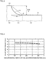
- FIG. 3 is an enlarged plan view of a portion near a slot opening portion 10 described below.
- a slot coil 5U is shown accommodated in only one slot 6U in FIG. 2 .
- Slot coils 5U, 5V, 5W are not shown in FIG. 3 . The slot coils 5U, 5V, 5W will be described later.
- the synchronous reluctance motor 1 (hereinafter simply referred to as the "motor 1") includes an annular stator 2 and a rotor 3.
- the stator 2 generates a rotating magnetic field.
- the rotor 3 is disposed radially inside the stator 2 and is rotated by the rotating magnetic field.
- the circumferential direction of the stator 2 is simply referred to as the circumferential direction
- the radial direction of the stator 2 is simply referred to as the radial direction.
- the direction toward the inside in the radial direction of the stator 2 is simply referred to as toward the inside in the radial direction, and the direction toward the outside in the radial direction of the stator 2 is simply referred to as toward the outside in the radial direction.
- the axial direction of the rotor 3 is simply referred to as the axial direction, and an object as viewed in plan from the axial direction is simply referred to an object as viewed in plan.
- the stator 2 includes an annular stator core 4 and slot coils 5U, 5V, 5W.
- the stator core 4 is formed by stacking a plurality of annular steel sheets.
- the stator core 4 has an inside diameter of about 50 mm and an outside diameter of about 90 mm.
- the stator core 4 has a plurality of (in the present embodiment, 24) slots 6U, 6V, 6W, a plurality of (in the present embodiment, 24) tooth portions 7, and an annular yoke portion 8.
- the plurality of slots 6U, 6V, 6W are located at regular intervals in the circumferential direction.
- Each of the plurality of tooth portions 7 is a portion located between two of the slots 6U, 6V, 6W which are adjacent to each other in the circumferential direction.
- the yoke portion 8 is a portion located radially outside the slots 6U, 6V, 6W and the tooth portions 7.
- each slot 6U, 6V, 6W has a quadrilateral shape extending in the radial direction as viewed in plan. All of the slots 6U, 6V, 6W have the same shape and the same area.
- each slot 6U, 6V, 6W includes a coil accommodating portion 9, a slot opening portion 10, and a slot connection portion 11.
- the coil accommodating portion 9 is a portion in which the slot coil 5U, 5V, 5W is accommodated.
- the slot opening portion 10 is located radially inside the coil accommodating portion 9.
- the slot connection portion 11 is located between the coil accommodating portion 9 and the slot opening portion 10 and connects the coil accommodating portion 9 and the slot opening portion 10.
- Each coil accommodating portion 9 has a quadrilateral shape extending in the radial direction as viewed in plan (in the present embodiment, a rectangular shape as viewed in plan).
- the circumferential width of each coil accommodating portion 9 is substantially uniform along the radial direction.
- the radial width of each coil accommodating portion 9 is substantially uniform along the circumferential direction.
- Each slot opening portion 10 has a quadrilateral shape extending in the circumferential direction as viewed in plan (in the present embodiment, a rectangular shape as viewed in plan).
- the circumferential width of each slot opening portion 10 is smaller than that of each coil accommodating portion 9.
- Each slot opening portion 10 communicates, at its radially outer end, with the coil accommodating portion 9 in the middle part in the circumferential direction of the coil accommodating portion 9 via the slot connection portion 11.
- Each slot connection portion 11 connects the radially inner end of the coil accommodating portion 9 and the radially outer end of the slot opening portion 10.
- each slot connection portion 11 is formed so that its circumferential width gradually increases toward the coil accommodating portion 9 from the slot opening portion 10. A predetermined angle is thus formed between the coil accommodating portion 9 and the slot connection portion 11.
- each tooth portion 7 includes a tooth body portion 12, an inner end 13, and a tooth connection portion 14.
- the tooth body portion 12 of each tooth portion 7 is a portion sandwiched between the coil accommodating portions 9 of two of the slots 6U, 6V, 6W which are adjacent to each other in the circumferential direction.
- the tooth body portion 12 has an outer end 12a and an inner end 12b.
- the outer end 12a is connected to the yoke portion 8 located radially outside the tooth body portion 12, and the inner end 12b is connected to the inner end 13 located radially inside the tooth body portion 12.
- the circumferential width of the tooth body portion 12 gradually increases toward the outside in the radial direction from the inside in the radial direction.
- the circumferential width of the outer end 12a of the tooth body portion 12 is thus larger than that of the inner end 12b of the tooth body portion 12.
- each tooth portion 7 is a portion sandwiched between the slot opening portions 10 of two of the slots 6U, 6V, 6W which are adjacent to each other in the circumferential direction.
- the circumferential width of the inner end 13 is larger than that of the inner end 12b of the tooth body portion 12.
- the tooth connection portion 14 of each tooth portion 7 is a portion sandwiched between the slot connection portions 11 of two of the slots 6U, 6V, 6W which are adjacent to each other in the circumferential direction.
- the tooth connection portion 14 of each tooth portion 7 connects the tooth body portion 12 and the inner end 13.
- the stator core 4 has three independent slot coils 5U, 5V, 5W wound therein.
- the three independent slot coils 5U, 5V, 5W include a U-phase slot coil 5U, a V-phase slot coil 5V, and a W-phase slot coil 5W.
- each slot coil 5U, 5V, 5W is formed by a wire containing copper and having a quadrilateral section, more specifically, a rectangular wire.
- Each slot coil 5U, 5V, 5W is wound in the slots 6U, 6V, 6W of a corresponding phase by distributed winding.
- each slot 6U, 6V, 6W includes a pair of slots 6Ua, 6Va, 6Wa formed at an interval in the circumferential direction with more than one (in the present embodiment, five) of the tooth portions 7 being interposed therebetween in the circumferential direction.
- Each slot coil 5U, 5V, 5W includes four winding portions 5Ua, 5Va, 5Wa wound in each pair of slots 6U, 6V, 6W of a corresponding phase.
- Each slot coil 5U, 5V, 5W includes a plurality of (in the present embodiment, four) conductor portions 15 disposed so as to extend in the axial direction and arranged in line in the radial direction.
- the four conductor portions 15 are wrapped together in insulating paper 16 and are disposed in the slot 6U, 6V, 6W with the insulating paper 16 interposed therebetween.
- the number of conductor portions 15 arranged in line is preferably an even number, and is four in the present embodiment.
- the number of conductor portions 15 may be other than four, such as two, six, or eight.
- ⁇ represents the resistivity of each slot coil 5U, 5V, 5W
- L represents the length of each slot coil 5U, 5V, 5W
- Se represents the sectional area of each conductor portion 15.
- r1 is 1/2 of the outside diameter of the stator core 4, and r2 is 1/2 of the inside diameter of the stator core 4.
- Y represents the radial width of the yoke portion 8, and Z represents the radial width of the slot opening portion 10.
- X represents the circumferential width of the coil accommodating portion 9
- M represents the circumferential width of the slot opening portion 10
- ⁇ represents the angle between the coil accommodating portion 9 and the slot connection portion 11 (hereinafter simply referred to as the opening angle).
- D represents the thickness of the insulating paper 16
- W represents the radial width of the slot connection portion 11.
- each slot coil 5U, 5V, 5W formed by a wire having a quadrilateral section is wound in the slots 6U, 6V, 6W of a corresponding phase by distributed winding.
- the slot coils 5U, 5V, 5W formed by a wire having a quadrilateral section (rectangular wire)
- clearance between the slot coil 5U, 5V, 5W and the slot 6U, 6V, 6W can be reduced as compared to the case where the slot coils 5U, 5V, 5W formed by a round wire having a circular section are wound with the same number of turns in the slots 6U, 6V, 6W.
- the slot coils 5U, 5V, 5W have a larger sectional area, winding resistance of the slots 6U, 6V, 6W can be reduced.
- the space factor of each slot coil 5U, 5V, 5W which is the proportion of the slot coil 5U, 5V, 5W in each slot 6U, 6V, 6W, can be increased while reducing the interterminal resistance R of each slot coil 5U, 5V, 5W.
- setting the interterminal resistance R of each slot coil 5U, 5V, 5W based on Expressions (1) to (3) can effectively increase the space factor of each slot coil 5U, 5V, 5W while satisfactorily reducing the interterminal resistance R of each slot coil 5U, 5V, 5W.
- Winding the slot coils 5U, 5V, 5W by distributed winding can make the winding factor closer to 1 as compared to the case of winding the slot coils 5U, 5V, 5W by concentrated winding. Since the interterminal resistance R of each slot coil 5U, 5V, 5W is reduced, the space factor thereof is increased, and the winding factor is improved, reluctance torque T, which is output torque of the motor 1, can be increased.
- H1 represents the circumferential width of the outer end 12a of the tooth body portion 12
- H2 represents the circumferential width of the inner end 12b of the tooth body portion 12.
- the average value H of the circumferential width of the tooth body portion 12 is set to a value equal to or larger than the circumferential width X of the coil accommodating portion 9 (X ⁇ H).
- the volume of each tooth portion 7 can be made larger than the capacity of each slot 6U, 6V, 6W. Since the volume of the stator core 4 is increased, magnetic resistance of the stator core 4 can be reduced, and magnetic utilization can thus be improved.
- the radial width Y of the yoke portion 8 may be set to a value equal to or larger than the average value H of the circumferential width of the tooth body portion 12 (H ⁇ Y). With this configuration, the volume of the stator core 4 can be effectively increased. Accordingly, the average value H of the circumferential width of the tooth body portion 12 may be set to a value equal to or larger than the circumferential width X of the coil accommodating portion 9 and equal to or smaller than the radial width Y of the yoke portion 8 (X ⁇ H ⁇ Y).
- FIG. 4 is a graph showing the simulation result of the reluctance torque T for various circumferential widths X of the coil accommodating portion 9.
- the average value H of the circumferential width of the tooth body portion 12 was 4.4 mm
- the radial width Y of the yoke portion 8 was 7.2 mm
- the radial width Z of the slot opening portion 10 was 0.5 mm
- the circumferential width M of the slot opening portion 10 was 0.5 mm
- the opening angle ⁇ was 100°.
- the reluctance torque T is 4 N ⁇ m or more when the circumferential width X of the coil accommodating portion 9 is 1.6 mm or more and 3.6 mm or less.
- the reluctance torque T decreases as the circumferential width X of the coil accommodating portion 9 increases. This is because, as the circumferential width X of the coil accommodating portion 9 increases, the average value H of the circumferential width of the tooth body portion 12 decreases and the magnetic resistance of the stator core 4 increases accordingly.
- the result of FIG. 4 shows that the reluctance torque T of 4 N ⁇ m or more can be satisfactorily achieved at least by setting the circumferential width X of the coil accommodating portion 9 to 1.6 mm or more and 3.6 mm or less.
- FIG. 5 is a graph showing the simulation result of magnetic flux density for various average values H of the circumferential width of the tooth body portion 12.
- the magnetic flux density herein means the density of magnetic flux passing through a single tooth portion 7.
- the circumferential width X of the coil accommodating portion 9 was 2.6 mm
- the radial width Y of the yoke portion 8 was 7.2 mm
- the radial width Z of the slot opening portion 10 was 0.5 mm
- the circumferential width M of the slot opening portion 10 was 0.5 mm
- the opening angle ⁇ was 100°.
- the magnetic flux density is 1.5 T or more when the average value H of the circumferential width of the tooth body portion 12 is 4 mm or more and 5 mm or less.
- the magnetic flux density increases as the average value H of the circumferential width of the tooth body portion 12 decreases.
- the magnetic flux density is as high as 2H or more when the average value H of the circumferential width of the tooth body portion 12 is less than 4.4.
- FIGS. 4 and 5 show that magnetic saturation can be restrained and satisfactory reluctance torque T can be achieved by setting the ratio X/H of the circumferential width X (1.6 mm or more and 3.6 mm or less) of the coil accommodating portion 9 to the average value H (4.4 mm or more and 5 mm or less) of the circumferential width of the tooth body portion 12 to 0.32 or more and 0.82 or less.
- FIG. 6 is a graph showing the simulation result of the reluctance torque T for various radial widths Y of the yoke portion 8.
- the circumferential width X of the coil accommodating portion 9 was 1.6 mm, 2.6 mm, and 3.6 mm
- the radial width Z of the slot opening portion 10 was 0.5 mm
- the circumferential width M of the slot opening portion 10 was 0.5 mm
- the opening angle ⁇ was 100°.
- FIG. 6 shows first to third lines L1, L2, L3.
- the first line L1 shows the relationship between the radial width Y of the yoke portion 8 and the reluctance torque T when the circumferential width X of the coil accommodating portion 9 is 1.6 mm.
- the second line L2 shows the relationship between the radial width Y of the yoke portion 8 and the reluctance torque T when the circumferential width X of the coil accommodating portion 9 is 2.6 mm.
- the third line L3 shows the relationship between the radial width Y of the yoke portion 8 and the reluctance torque T when the circumferential width X of the coil accommodating portion 9 is 3.6 mm.
- the reluctance torque T when the radial width Y of the yoke portion 8 is 6 mm or more and 9 mm or less, the reluctance torque T is 3.5 N ⁇ m or more for all of the above three values of the circumferential width X of the coil accommodating portion 9.
- the reluctance torque T when the radial width Y of the yoke portion 8 is 6.6 mm or more and 9 mm or less, the reluctance torque T is 4 N ⁇ m or more.
- the reluctance torque T increases as the radial width Y of the yoke portion 8 increases. This is because, as the radial width Y of the yoke portion 8 increases, the magnetic resistance of the stator core 4 decreases and thus the magnetic utilization improves accordingly.
- the reluctance torque T decreases as the circumferential width X of the coil accommodating portion 9 increases. This is because, as the circumferential width X of the coil accommodating portion 9 increases, the average value H of the circumferential width of the tooth body portion 12 decreases and the magnetic resistance of the stator core 4 increases accordingly, as described above.
- FIGS. 4 and 6 show that magnetic saturation can be satisfactorily restrained and satisfactory reluctance torque T can be achieved by setting the ratio Y/H of the radial width Y (6 mm or more and 9 mm or less) of the yoke portion 8 to the average value H (4.4 mm or more and 5 mm or less) of the circumferential width of the tooth body portion 12 to 1.2 or more and 2 or less.
- the average value H of the circumferential width of the tooth body portion 12 may be set to a value equal to or smaller than the radial width Y of the yoke portion 8.
- the ratio Y/H of the radial width Y (6 mm or more and 9 mm or less) of the yoke portion 8 to the average value H (4.4 mm or more and 5 mm or less) of the circumferential width of the tooth body portion 12 may be 1 or more and 2 or less.
- FIG. 7 is a graph showing the simulation result of the reluctance torque T for various ratios M/X of the circumferential width M of the slot opening portion 10 to the circumferential width X of the coil accommodating portion 9 (0 ⁇ M/X ⁇ 1).
- the circumferential width X of the coil accommodating portion 9 was 2.6 mm
- the average value H of the circumferential width of the tooth body portion 12 was 4.4 mm
- the radial width Y of the yoke portion 8 was 7.2 mm
- the radial width Z of the slot opening portion 10 was 0.5 mm
- the opening angle ⁇ was 100°.
- the ratio M/X of the circumferential width M of the slot opening portion 10 to the circumferential width X of the coil accommodating portion 9 was varied in the range of 0.076 to 0.85, both inclusive. More specifically, the circumferential width X of the coil accommodating portion 9 was 2.6 mm, and the circumferential width M of the slot opening portion 10 was varied in the range of 0.2 mm to 2.2 mm, both inclusive.
- the reluctance torque T is 4.28 N ⁇ m or more when the ratio M/X of the circumferential width M of the slot opening portion 10 to the circumferential width X of the coil accommodating portion 9 is 0.076 or more and 0.85 or less (that is, when the circumferential width M of the slot opening portion 10 is 0.2 mm or more and 2.2 mm or less).
- the reluctance torque T is 4.38 N ⁇ m or more when the ratio M/X of the circumferential width M of the slot opening portion 10 to the circumferential width X of the coil accommodating portion 9 is 0.2 or more and 0.74 or less (that is, when the circumferential width M of the slot opening portion 10 is 0.5 mm or more and 1.9 mm or less).
- FIG. 8 is a graph showing the simulation result of torque ripple of the reluctance torque T in FIG. 7 .
- the torque ripple is 10% or less when the ratio M/X of the circumferential width M of the slot opening portion 10 to the circumferential width X of the coil accommodating portion 9 is 0.076 or more and 0.74 or less (that is, when the circumferential width M of the slot opening portion 10 is 0.2 mm or more and 1.9 mm or less).
- the torque ripple is 8% or less when the ratio M/X of the circumferential width M of the slot opening portion 10 to the circumferential width X of the coil accommodating portion 9 is 0.39 or more and 0.62 or less (that is, when the circumferential width M of the slot opening portion 10 is 1 mm or more and 1.6 mm or less).
- FIG. 7 shows that the reluctance torque T decreases as the ratio M/X of the circumferential width M of the slot opening portion 10 to the circumferential width X of the coil accommodating portion 9 becomes closer to 0 or 1, and that the reluctance torque T has a maximum value between when the ratio M/X is 0 and when the ratio M/X is 1.
- the slot opening portion 10 is substantially closed by the inner end 13 of the tooth portion 7. In this case, adjacent ones of the tooth portions 7 are substantially magnetically connected by the inner ends 13, and magnetism is not appropriately utilized. This results in reduced magnetic utilization and reduced reluctance torque T.
- the ratio M/X of the circumferential width M of the slot opening portion 10 to the circumferential width X of the coil accommodating portion 9 is approximately 1, there is no inner end 13 radially inside the coil accommodating portion 9. In this case, the magnetic resistance of the tooth portion 7 increases, which results in reduced magnetic utilization and reduced reluctance torque T.
- setting the ratio M/X of the circumferential width M of the slot opening portion 10 to the circumferential width X of the coil accommodating portion 9 to an appropriate value under the condition of 0 ⁇ M/X ⁇ 1 improves the magnetic utilization, whereby satisfactory reluctance torque T can be achieved.
- setting the ratio M/X of the circumferential width M of the slot opening portion 10 to the circumferential width X of the coil accommodating portion 9 to an appropriate value can also satisfactorily reduce the torque ripple as the magnetic utilization is improved.
- the simulation results of FIGS. 7 and 8 show that it is preferable to set the ratio M/X of the circumferential width M of the slot opening portion 10 to the circumferential width X of the coil accommodating portion 9 to 0.2 or more and 0.74 or less (that is, the circumferential width M of the slot opening portion 10 is 0.5 mm or more and 1.9 mm or less).
- the ratio M/X being in this range, the reluctance torque T of 4.38 N ⁇ m or more and the torque ripple of 10% or less can be achieved.
- the simulation results of FIGS. 7 and 8 also show that it is more preferable to set the ratio M/X of the circumferential width M of the slot opening portion 10 to the circumferential width X of the coil accommodating portion 9 to 0.39 or more and 0.62 or less (that is, the circumferential width M of the slot opening portion 10 is 1 mm or more and 1.6 mm or less).
- the ratio M/X being in this range, the reluctance torque T of 4.4 N ⁇ m or more and the torque ripple of 8% or less can be achieved.
- FIG. 9 is a graph showing the simulation result of the reluctance torque T for various opening angles ⁇ .
- FIG. 10 is a graph showing the simulation result of torque ripple of the reluctance torque T in FIG. 9 .
- the circumferential width X of the coil accommodating portion 9 was 2.6 mm
- the average value H of the circumferential width of the tooth body portion 12 was 4.4 mm
- the radial width Y of the yoke portion 8 was 7.2 mm
- the radial width Z of the slot opening portion 10 was 0.5 mm
- the circumferential width M of the slot opening portion 10 was 0.5 mm.
- the reluctance torque T when the opening angle ⁇ is 80° or more and 130° or less, the reluctance torque T is 4.2 N ⁇ m or more. Referring to FIG. 9 , when the opening angle ⁇ becomes less than 90°, the reluctance torque T decreases sharply. The reason for this is as follows. When the opening angle ⁇ is set to less than 90°, the tip of the inner end 13 of the tooth portion 7 projects toward the coil accommodating portion 9 (that is, toward the outside in the radial direction), and the tip of the inner end 13 of the tooth portion 7 and the tooth body portion 12 face each other in the circumferential direction. This causes leakage of magnetic flux between the tip of the inner end 13 of the tooth portion 7 and the tooth body portion 12, which reduces the magnetic utilization.
- the torque ripple does not vary significantly with a change in opening angle ⁇ .
- the torque ripple is 10% or less for every value of the opening angle ⁇ .
- the results of FIGS. 9 and 10 show that it is preferable to set the opening angle ⁇ to 90° or more and 130° or less.
- the rotor 3 has four poles (two pairs of poles) in the present embodiment.
- the rotor 3 includes a rotor core 20 and a rotation shaft 21 extending through the central part of the rotor core 20 and fixed to the rotor core 20.
- the rotor core 20 is formed by stacking a plurality of circular electromagnetic steel sheets each having a hole in its central part.
- FIG. 11 is an enlarged plan view showing only the rotor 3 of the synchronous reluctance motor 1 in FIG. 1 .
- the rotor core 20 has flux barrier groups formed at intervals in the circumferential direction.
- the number of flux barrier groups corresponds to the number of poles.
- Each of the flux barrier groups consists of a plurality of arc-shaped flux barriers (in this example, slits (air layers)) 22 that are arranged in a plurality of layers from the outer periphery of the rotor core 20 toward the rotation shaft 21 and that are convex toward the rotation shaft 21.
- the rotor core 20 has four flux barrier groups formed at intervals in the circumferential direction.
- the flux barriers 22 of each flux barrier group are arranged in seven layers. That is, each flux barrier group consists of seven flux barriers 22 having different lengths.
- the flux barriers 22 need not necessarily be slits.
- the flux barriers 22 may be made of a nonmagnetic material such as resin.
- a rib 23 refers to a region of the rotor core 20 which is sandwiched between adjacent two of the flux barriers 22 of the same flux barrier group as viewed in plan.
- a q-axis is an axis extending through the midpoints in the circumferential direction of the flux barriers 22 of each flux barrier group and extending in the radial direction of the rotor core 20.
- a d-axis is an axis extending between adjacent two of the flux barrier groups and extending in the radial direction of the rotor core 20.
- the flux barriers 22 impede the flow of magnetic flux. Accordingly, the magnetic flux from the stator core 4 is less likely to flow in the direction from one of adjacent two of the q-axes to the other. However, due to the ribs 23 each located between the flux barriers 22, the magnetic flux from the stator core 4 tends to flow in the direction from one of adjacent two of the d-axes to the other.
- reluctance torque T is generated from the motor 1.
- the reluctance torque T is given by the following Expression (5).
- T pn ⁇ Ld ⁇ Lq ⁇ Id ⁇ Iq
- pn represents the number of pole pairs
- Ld represents d-axis inductance
- Lq represents q-axis inductance
- Id represents a d-axis current
- Iq represents a q-axis current.
- the reluctance torque T therefore increases as the difference between the d-axis inductance Ld and the q-axis inductance Lq, namely (Ld - Lq), increases.
- the flux barriers 22 are formed to increase the magnetic resistance of a magnetic path in the q-axis direction and to reduce the magnetic resistance of a magnetic path in the d-axis direction.
- the flux barriers 22 are designed to have an appropriate shape as viewed in plan.
- the shape of the flux barriers 22 as viewed in plan will be described in detail.
- A, B, C, and D refer to the midpoints in the circumferential direction of the flux barrier groups which are located on the outer peripheral edge of the rotor 3.
- a polygonal region (in this example, a quadrilateral region) 24 is a region of the rotor 3 which is surrounded by a polygon (in this example, a quadrangle) having vertices A, B, C, D as viewed in plan.
- the side or the line segment connecting the vertices A, B of the polygonal region 24 is sometimes referred to as A-B
- the side or the line segment connecting the vertices B, C of the polygonal region 24 is sometimes referred to as B-C
- the side or the line segment connecting the vertices C, D of the polygonal region 24 is sometimes referred to as C-D
- the side or the line segment connecting the vertices D, A of the polygonal region 24 is sometimes referred to as D-A.
- the plurality of flux barriers 22 of each flux barrier group are formed by arc-shaped portions 22a located inside the polygonal region 24 and linear portions 22b located outside the polygonal region 24 and extending from both ends of each arc-shaped portion 22a, as viewed in plan.
- the center of the arcs of the plurality of arc-shaped portions 22a of each flux barrier group is located at the midpoint A, B, C, D in the circumferential direction of that flux barrier group which is located on the outer peripheral edge of the rotor 3.
- the linear portion 22b extending from each end of the arc-shaped portion 22a extends in the direction perpendicular to one of the four sides of the polygonal region 24 which is located close to that end of the arc-shaped portion 22a, as viewed in plan. In other words, the linear portion 22b extending from each end of the arc-shaped portion 22a extends in the direction tangential to the arc-shaped portion 22a from that end of the arc-shaped portion 22a.
- the plurality of flux barriers 22 of one flux barrier group are formed by a plurality of arc-shaped portions 22a whose center is located at the point A, a plurality of linear portions 22b extending perpendicularly to the side A-B from one end on the side A-B of the arc-shaped portions 22a, and a plurality of linear portions 22b extending perpendicularly to the side D-A from one end on the side D-A of the arc-shaped portions 22a, as viewed in plan.
- ⁇ represents an angle between the plane of the planar circuit and the direction of the magnetic flux.
- Expression (6) shows that the magnetic flux ⁇ is maximum when the angle ⁇ between the plane of the planar circuit and the direction of the magnetic flux is 90 degrees.
- the magnetic flux flowing in the d-axis direction passes through the ribs 23 perpendicularly to the sections of the ribs 23 taken along the line segment D-A, and the sectional area of each rib 23 through which the magnetic flux passes, taken along the line segment D-A, is maximum.
- the magnetic utilization is thus improved, whereby the reluctance torque T can be increased.
- the arc-shaped portions 22a can be formed to a position closer to the center of the rotor 3 as compared to the case where the center of the arcs of the flux barriers 22 is located at a position outside the outer peripheral edge of the rotor 3 on the q-axis.
- the width of the ribs 23 can thus be increased, whereby the magnetic resistance of the magnetic path in the d-axis direction can be reduced.
- the reluctance torque T can thus be increased.
- the number of slots 6U, 6V, 6W and the number of tooth portions 7 are 24.
- the number of slots 6U, 6V, 6W and the number of tooth portions 7 may be more than 24.
- the number of slots 6U, 6V, 6W and the number of tooth portions 7 may be 36, 48, 96, etc.
- the rotor 3 has four poles (two pairs of poles).
- the number of poles of the rotor 3 may be other than four.
- the rotor 3 may have six poles (three pairs of poles), eight poles (four pairs of poles), etc.
- the flux barriers 22 are arranged in seven layers.
- the number of layers of the flux barriers 22 may be other than seven.
- the flux barriers 22 may be arranged in five layers, six layers, eight layers, nine layers, etc.
- the slot coils 5U, 5V, 5W may be formed by segment conductors. That is, the slot coil 5U, 5V, 5W of each phase may be configured so that U-shaped segment conductors having a pair of tip ends are accommodated in the four pairs of slots 6U, 6V, 6W of a corresponding phase and are connected together with the tip ends of each segment conductor being bonded together in a predetermined manner. Forming the slot coils 5U, 5V, 5W by the segment conductors facilitates attachment of the slot coils 5U, 5V, 5W to the stator core 4.
- each slot opening portion 10 is 0.5 mm.
- the radial width Z of each slot opening portion 10 may be, e.g., 0.3 mm or more and 1.0 mm or less.
- the radial width of the inner end 13 of each tooth portion 7 is also 0.3 mm or more and 1.0 mm or less, whereby the magnetic resistance can be reduced in the inner end 13. The magnetic utilization can thus be satisfactorily improved.
- the present invention can be applied to synchronous motors that are used in electric power steering systems.
- the present invention is also applicable to synchronous motors that are used in systems other than electric power steering systems.
- a synchronous reluctance motor (1) includes: an annular stator (2); and a rotor (3) disposed radially inside the stator.
- the stator includes an annular stator core (4) having in its inner peripheral portion a plurality of slots (6U, 6V, 6W) located at an interval in a circumferential direction of the stator, and slot coils (5U, 5V, 5W) accommodated in the slots.
- Each of the slots is formed by a coil accommodating portion (12) extending in a radial direction of the stator and accommodating the slot coil, and a slot opening portion (13) communicating with the coil accommodating portion at a radially inner end of the coil accommodating portion.
- a ratio (M/X) of a circumferential width (M) of the slot opening portion to a circumferential width (X) of the coil accommodating portion is set to 0.076 or more and 0.85 or less.
- the ratio of the circumferential width of the slot opening portion to the circumferential width of the coil accommodating portion is set to 0.076 or more and 0.85 or less. This can satisfactorily improve magnetic utilization, whereby output torque can be increased. Since the magnetic utilization is improved, torque ripple can be reduced.
- each of the slots may include a slot connection portion (11) located between the coil accommodating portion and the slot opening portion and connecting the coil accommodating portion and the slot opening portion.
- An angle ( ⁇ ) between the coil accommodating portion and the slot connection portion may be set to 90° or more and 130° or less.
- the plurality of slots may be located at a regular interval in the circumferential direction.
- the slot opening portion may communicate with the coil accommodating portion in a middle part in the circumferential direction of the coil accommodating portion.
- the stator core may include a tooth portion (7) that is a portion between the slots adjacent to each other in the circumferential direction.
- the tooth portion may have a circumferential width that gradually decreases toward the inside in the radial direction.
- An average value (H) of the circumferential width of the tooth portion may be set to a value equal to or larger than the circumferential width of the coil accommodating portion.
- the ratio of the circumferential width of the slot opening portion to the circumferential width of the coil accommodating portion may be set to 0.2 or more and 0.74 or less.
- output torque may be 4 N ⁇ m or more and torque ripple may be 10% or less.
Landscapes
- Engineering & Computer Science (AREA)
- Power Engineering (AREA)
- Synchronous Machinery (AREA)
- Iron Core Of Rotating Electric Machines (AREA)
Abstract
A synchronous reluctance motor 1 includes: an annular stator 2; and a rotor 3 disposed radially inside the stator 2. The stator 2 includes an annular stator core 4 having in its inner peripheral portion a plurality of slots 6U, 6V, 6W located at intervals in a circumferential direction of the stator 2, and slot coils 5U, 5V, 5W accommodated in the slots 6U, 6V, 6W. The slot coils 5U, 5V, 5W are formed by a wire having a quadrilateral section and are wound in the slots 6U, 6V, 6W by distributed winding.
Description
- The present invention relates to synchronous reluctance motors that are used for, e.g., electric power steering systems.
- Reluctance motors are known which rotate a rotor by using only reluctance torque generated by a change in electromagnetic energy with respect to the position. The reluctance motors include switched reluctance motors and synchronous reluctance motors. In the switched reluctance motors, a stator and a rotor have a magnetic saliency. In the synchronous reluctance motors, a stator has a structure similar to that of a brushless motor.
- In the synchronous reluctance motors, only a rotor has a magnetic saliency out of the stator and the rotor. In the synchronous reluctance motors, there are a salient direction in which magnetic flux tends to flow (hereinafter referred to as the "d-axis direction") and a non-salient direction in which the magnetic flux is less likely to flow (hereinafter referred to as the "q-axis direction") due to the magnetic saliency of the rotor. Accordingly, reluctance torque is generated due to the difference between inductance in the d-axis direction and inductance in the q-axis direction, and the rotor is rotated by the reluctance torque. See, e.g., Japanese Patent Application Publication No.
H11-289730 JP H11-289730 A - The synchronous reluctance motors do not use permanent magnets, and rotate the rotor by using only the reluctance torque. The synchronous reluctance motors are therefore disadvantageous in that their output torque is smaller than that of motors using permanent magnets. It is desired to increase the output torque of the synchronous reluctance motors as much as possible.
- It is one object of the present invention to provide a synchronous reluctance motor that can generate larger output torque.
- According to one aspect of the present invention, a synchronous reluctance motor includes: an annular stator; and a rotor disposed radially inside the stator. The stator includes an annular stator core having in its inner peripheral portion a plurality of slots located at an interval in a circumferential direction of the stator, and slot coils accommodated in the slots. The slot coils are formed by a wire having a quadrilateral section and are wound in the slots by distributed winding.
- In the synchronous reluctance motor of the above aspect, the slot coils are formed by a wire having a quadrilateral section. In this case, clearance between the slot coils in the state where the slot coils are accommodated in the slots can be reduced as compared to the case where the slot coils are formed by a round wire having a circular section. A space factor of the slot coil, which is the proportion of the slot coil in the slot, can be thus increased.
- In the synchronous reluctance motor of the above aspect, the slot coils are wound by distributed winding. Accordingly, a winding factor can be made closer to 1 as compared to the case where the slot coils are wound by concentrated winding. Since the space factor of the slot coil is increased and the winding factor is improved, output torque can be increased.
- The foregoing and further features and advantages of the invention will become apparent from the following description of example embodiments with reference to the accompanying drawings, wherein like numerals are used to represent like elements and wherein:
-
FIG. 1 is a sectional view showing the configuration of a synchronous reluctance motor according to an embodiment of the present invention; -
FIG. 2 is an enlarged plan view of a portion surrounded by alternate long and short dash line II inFIG. 1 ; -
FIG. 3 is an enlarged plan view of a portion near a slot opening portion; -
FIG. 4 is a graph showing the simulation result of output torque for various circumferential widths of a coil accommodating portion of each slot; -
FIG. 5 is a graph showing the simulation result of magnetic flux density for various average values of the circumferential width of a tooth body portion; -
FIG. 6 is a graph showing the simulation result of the output torque for various radial widths of a yoke portion; -
FIG. 7 is a graph showing the simulation result of the output torque for various ratios of the circumferential width of the slot opening portion to the circumferential width of the coil accommodating portion of each slot; -
FIG. 8 is a graph showing the simulation result of torque ripple of the output torque inFIG. 7 ; -
FIG. 9 is a graph showing the simulation result of the output torque for various angles between the coil accommodating portion and a slot connection portion; -
FIG. 10 is a graph showing the simulation result of torque ripple of the output torque inFIG. 9 ; and -
FIG. 11 is an enlarged plan view showing only a rotor of the synchronous reluctance motor inFIG. 1 . - An embodiment of the present invention will be described in detail below with reference to the accompanying drawings.
-
FIG. 1 is a sectional view showing the configuration of asynchronous reluctance motor 1 according to an embodiment of the present invention.FIG. 2 is an enlarged plan view of a portion surrounded by alternate long and short dash line II inFIG. 1 .FIG. 3 is an enlarged plan view of a portion near aslot opening portion 10 described below. For convenience of description, aslot coil 5U is shown accommodated in only oneslot 6U inFIG. 2 .Slot coils FIG. 3 . Theslot coils - Referring to
FIG. 1 , the synchronous reluctance motor 1 (hereinafter simply referred to as the "motor 1") includes anannular stator 2 and arotor 3. Thestator 2 generates a rotating magnetic field. Therotor 3 is disposed radially inside thestator 2 and is rotated by the rotating magnetic field. Hereinafter, the circumferential direction of thestator 2 is simply referred to as the circumferential direction, and the radial direction of thestator 2 is simply referred to as the radial direction. The direction toward the inside in the radial direction of thestator 2 is simply referred to as toward the inside in the radial direction, and the direction toward the outside in the radial direction of thestator 2 is simply referred to as toward the outside in the radial direction. The axial direction of therotor 3 is simply referred to as the axial direction, and an object as viewed in plan from the axial direction is simply referred to an object as viewed in plan. - The
stator 2 includes anannular stator core 4 andslot coils stator core 4 is formed by stacking a plurality of annular steel sheets. In the present embodiment, thestator core 4 has an inside diameter of about 50 mm and an outside diameter of about 90 mm. - The
stator core 4 has a plurality of (in the present embodiment, 24)slots tooth portions 7, and anannular yoke portion 8. The plurality ofslots tooth portions 7 is a portion located between two of theslots yoke portion 8 is a portion located radially outside theslots tooth portions 7. - Referring to
FIG. 2 , eachslot slots slot coil accommodating portion 9, aslot opening portion 10, and aslot connection portion 11. The coilaccommodating portion 9 is a portion in which theslot coil slot opening portion 10 is located radially inside thecoil accommodating portion 9. Theslot connection portion 11 is located between thecoil accommodating portion 9 and theslot opening portion 10 and connects thecoil accommodating portion 9 and theslot opening portion 10. - Each
coil accommodating portion 9 has a quadrilateral shape extending in the radial direction as viewed in plan (in the present embodiment, a rectangular shape as viewed in plan). The circumferential width of eachcoil accommodating portion 9 is substantially uniform along the radial direction. The radial width of eachcoil accommodating portion 9 is substantially uniform along the circumferential direction. - Each
slot opening portion 10 has a quadrilateral shape extending in the circumferential direction as viewed in plan (in the present embodiment, a rectangular shape as viewed in plan). The circumferential width of eachslot opening portion 10 is smaller than that of eachcoil accommodating portion 9. Eachslot opening portion 10 communicates, at its radially outer end, with thecoil accommodating portion 9 in the middle part in the circumferential direction of thecoil accommodating portion 9 via theslot connection portion 11. - Each
slot connection portion 11 connects the radially inner end of thecoil accommodating portion 9 and the radially outer end of theslot opening portion 10. In the present embodiment, eachslot connection portion 11 is formed so that its circumferential width gradually increases toward thecoil accommodating portion 9 from theslot opening portion 10. A predetermined angle is thus formed between thecoil accommodating portion 9 and theslot connection portion 11. - Referring to
FIG. 2 , eachtooth portion 7 includes atooth body portion 12, aninner end 13, and atooth connection portion 14. Thetooth body portion 12 of eachtooth portion 7 is a portion sandwiched between thecoil accommodating portions 9 of two of theslots tooth body portion 12 has anouter end 12a and aninner end 12b. Theouter end 12a is connected to theyoke portion 8 located radially outside thetooth body portion 12, and theinner end 12b is connected to theinner end 13 located radially inside thetooth body portion 12. In the present embodiment, the circumferential width of thetooth body portion 12 gradually increases toward the outside in the radial direction from the inside in the radial direction. The circumferential width of theouter end 12a of thetooth body portion 12 is thus larger than that of theinner end 12b of thetooth body portion 12. - The
inner end 13 of eachtooth portion 7 is a portion sandwiched between theslot opening portions 10 of two of theslots inner end 13 is larger than that of theinner end 12b of thetooth body portion 12. Thetooth connection portion 14 of eachtooth portion 7 is a portion sandwiched between theslot connection portions 11 of two of theslots tooth connection portion 14 of eachtooth portion 7 connects thetooth body portion 12 and theinner end 13. - Referring to
FIGS. 1 and2 , thestator core 4 has three independent slot coils 5U, 5V, 5W wound therein. In the present embodiment, the three independent slot coils 5U, 5V, 5W include aU-phase slot coil 5U, a V-phase slot coil 5V, and a W-phase slot coil 5W. In the present embodiment, eachslot coil slot coil slots - More specifically, the plurality of
slots U-phase slot 6U in which theU-phase slot coil 5U is wound by distributed winding, a V-phase slot 6V in which the V-phase slot coil 5V is wound by distributed winding, and a W-phase slot 6W in which the W-phase slot coil 5W is wound by distributed winding. Referring toFIG. 1 , eachslot tooth portions 7 being interposed therebetween in the circumferential direction. In the present embodiment, four pairs of slots 6Ua, 6Va, 6Wa are arranged at regular intervals in the circumferential direction. Eachslot coil slots - The configuration in one
slot FIG. 2 . Eachslot coil conductor portions 15 disposed so as to extend in the axial direction and arranged in line in the radial direction. The fourconductor portions 15 are wrapped together in insulatingpaper 16 and are disposed in theslot paper 16 interposed therebetween. The number ofconductor portions 15 arranged in line is preferably an even number, and is four in the present embodiment. The number ofconductor portions 15 may be other than four, such as two, six, or eight. - Interterminal resistance R of each
slot coil 


- In Expression (1), ρ represents the resistivity of each
slot coil slot coil conductor portion 15. - Referring to
FIGS. 2 and3 , in Expressions (2) and (3), n represents the number ofconductor portions 15 that are accommodated in the coil accommodating portion 9 (in the present embodiment, n = 4), r1 represents the distance between the rotation center point P of therotor 3 and the outer edge of thestator 2, and r2 represents the distance between the rotation center point P of therotor 3 and the inner edge of thestator 2. In the present embodiment, r1 is 1/2 of the outside diameter of thestator core 4, and r2 is 1/2 of the inside diameter of thestator core 4. Y represents the radial width of theyoke portion 8, and Z represents the radial width of theslot opening portion 10. X represents the circumferential width of thecoil accommodating portion 9, M represents the circumferential width of theslot opening portion 10, and θ represents the angle between thecoil accommodating portion 9 and the slot connection portion 11 (hereinafter simply referred to as the opening angle). D represents the thickness of the insulatingpaper 16, and W represents the radial width of theslot connection portion 11. - In the present embodiment, each
slot coil slots slot coil slot slots slots - The space factor of each
slot coil slot coil slot slot coil slot coil slot coil slot coil - Winding the slot coils 5U, 5V, 5W by distributed winding can make the winding factor closer to 1 as compared to the case of winding the slot coils 5U, 5V, 5W by concentrated winding. Since the interterminal resistance R of each
slot coil motor 1, can be increased. - The relationship among the average value of the circumferential width of the
tooth body portion 12, the circumferential width X of thecoil accommodating portion 9, and the radial width Y of theyoke portion 8 will be described. The average value H of the circumferential width of thetooth body portion 12 is given by the following Expression (4).
- In Expression (4), H1 represents the circumferential width of the
outer end 12a of thetooth body portion 12, and H2 represents the circumferential width of theinner end 12b of thetooth body portion 12. - It is preferable to set the average value H of the circumferential width of the
tooth body portion 12 to a value equal to or larger than the circumferential width X of the coil accommodating portion 9 (X ≤ H). With this configuration, the volume of eachtooth portion 7 can be made larger than the capacity of eachslot stator core 4 is increased, magnetic resistance of thestator core 4 can be reduced, and magnetic utilization can thus be improved. - The radial width Y of the
yoke portion 8 may be set to a value equal to or larger than the average value H of the circumferential width of the tooth body portion 12 (H ≤ Y). With this configuration, the volume of thestator core 4 can be effectively increased. Accordingly, the average value H of the circumferential width of thetooth body portion 12 may be set to a value equal to or larger than the circumferential width X of thecoil accommodating portion 9 and equal to or smaller than the radial width Y of the yoke portion 8 (X ≤ H ≤ Y). - Specific values of the circumferential width X of the
coil accommodating portion 9, the average value H of the circumferential width of thetooth body portion 12, the radial width Y of theyoke portion 8, the radial width Z of theslot opening portion 10, the circumferential width M of theslot opening portion 10, and the opening angle θ will be described with reference toFIGS. 4 to 9 . -
FIG. 4 is a graph showing the simulation result of the reluctance torque T for various circumferential widths X of thecoil accommodating portion 9. - In this simulation, the average value H of the circumferential width of the
tooth body portion 12 was 4.4 mm, the radial width Y of theyoke portion 8 was 7.2 mm, the radial width Z of theslot opening portion 10 was 0.5 mm, the circumferential width M of theslot opening portion 10 was 0.5 mm, and the opening angle θ was 100°. - Referring to
FIG. 4 , the reluctance torque T is 4 N·m or more when the circumferential width X of thecoil accommodating portion 9 is 1.6 mm or more and 3.6 mm or less. Referring toFIG. 4 , the reluctance torque T decreases as the circumferential width X of thecoil accommodating portion 9 increases. This is because, as the circumferential width X of thecoil accommodating portion 9 increases, the average value H of the circumferential width of thetooth body portion 12 decreases and the magnetic resistance of thestator core 4 increases accordingly. The result ofFIG. 4 shows that the reluctance torque T of 4 N·m or more can be satisfactorily achieved at least by setting the circumferential width X of thecoil accommodating portion 9 to 1.6 mm or more and 3.6 mm or less. -
FIG. 5 is a graph showing the simulation result of magnetic flux density for various average values H of the circumferential width of thetooth body portion 12. The magnetic flux density herein means the density of magnetic flux passing through asingle tooth portion 7. - In this simulation, the circumferential width X of the
coil accommodating portion 9 was 2.6 mm, the radial width Y of theyoke portion 8 was 7.2 mm, the radial width Z of theslot opening portion 10 was 0.5 mm, the circumferential width M of theslot opening portion 10 was 0.5 mm, and the opening angle θ was 100°. - Referring to
FIG. 5 , the magnetic flux density is 1.5 T or more when the average value H of the circumferential width of thetooth body portion 12 is 4 mm or more and 5 mm or less. Referring toFIG. 5 , the magnetic flux density increases as the average value H of the circumferential width of thetooth body portion 12 decreases. In particular, the magnetic flux density is as high as 2H or more when the average value H of the circumferential width of thetooth body portion 12 is less than 4.4. - This is because, as the average value H of the circumferential width of the
tooth body portion 12 decreases and the circumferential width X of thecoil accommodating portion 9 increases, the magnetic resistance increases and the magnetic utilization decreases accordingly, which causes magnetic saturation. This result shows that, in order to restrain magnetic saturation, it is preferable to set the average value H of the circumferential width of thetooth body portion 12 to 4.4 mm or more and 5 mm or less. - The results of
FIGS. 4 and5 show that magnetic saturation can be restrained and satisfactory reluctance torque T can be achieved by setting the ratio X/H of the circumferential width X (1.6 mm or more and 3.6 mm or less) of thecoil accommodating portion 9 to the average value H (4.4 mm or more and 5 mm or less) of the circumferential width of thetooth body portion 12 to 0.32 or more and 0.82 or less. -
FIG. 6 is a graph showing the simulation result of the reluctance torque T for various radial widths Y of theyoke portion 8. - In this simulation, the circumferential width X of the
coil accommodating portion 9 was 1.6 mm, 2.6 mm, and 3.6 mm, the radial width Z of theslot opening portion 10 was 0.5 mm, the circumferential width M of theslot opening portion 10 was 0.5 mm, and the opening angle θ was 100°. -
FIG. 6 shows first to third lines L1, L2, L3. The first line L1 shows the relationship between the radial width Y of theyoke portion 8 and the reluctance torque T when the circumferential width X of thecoil accommodating portion 9 is 1.6 mm. The second line L2 shows the relationship between the radial width Y of theyoke portion 8 and the reluctance torque T when the circumferential width X of thecoil accommodating portion 9 is 2.6 mm. The third line L3 shows the relationship between the radial width Y of theyoke portion 8 and the reluctance torque T when the circumferential width X of thecoil accommodating portion 9 is 3.6 mm. - Referring to
FIG. 6 , when the radial width Y of theyoke portion 8 is 6 mm or more and 9 mm or less, the reluctance torque T is 3.5 N·m or more for all of the above three values of the circumferential width X of thecoil accommodating portion 9. In particular, when the radial width Y of theyoke portion 8 is 6.6 mm or more and 9 mm or less, the reluctance torque T is 4 N·m or more. - Referring to
FIG. 6 , the reluctance torque T increases as the radial width Y of theyoke portion 8 increases. This is because, as the radial width Y of theyoke portion 8 increases, the magnetic resistance of thestator core 4 decreases and thus the magnetic utilization improves accordingly. Referring toFIG. 6 , the reluctance torque T decreases as the circumferential width X of thecoil accommodating portion 9 increases. This is because, as the circumferential width X of thecoil accommodating portion 9 increases, the average value H of the circumferential width of thetooth body portion 12 decreases and the magnetic resistance of thestator core 4 increases accordingly, as described above. - The results of
FIGS. 4 and6 show that magnetic saturation can be satisfactorily restrained and satisfactory reluctance torque T can be achieved by setting the ratio Y/H of the radial width Y (6 mm or more and 9 mm or less) of theyoke portion 8 to the average value H (4.4 mm or more and 5 mm or less) of the circumferential width of thetooth body portion 12 to 1.2 or more and 2 or less. The average value H of the circumferential width of thetooth body portion 12 may be set to a value equal to or smaller than the radial width Y of theyoke portion 8. Accordingly, the ratio Y/H of the radial width Y (6 mm or more and 9 mm or less) of theyoke portion 8 to the average value H (4.4 mm or more and 5 mm or less) of the circumferential width of thetooth body portion 12 may be 1 or more and 2 or less. -
FIG. 7 is a graph showing the simulation result of the reluctance torque T for various ratios M/X of the circumferential width M of theslot opening portion 10 to the circumferential width X of the coil accommodating portion 9 (0 < M/X < 1). - In this simulation, the circumferential width X of the
coil accommodating portion 9 was 2.6 mm, the average value H of the circumferential width of thetooth body portion 12 was 4.4 mm, the radial width Y of theyoke portion 8 was 7.2 mm, the radial width Z of theslot opening portion 10 was 0.5 mm, and the opening angle θ was 100°. - The ratio M/X of the circumferential width M of the
slot opening portion 10 to the circumferential width X of thecoil accommodating portion 9 was varied in the range of 0.076 to 0.85, both inclusive. More specifically, the circumferential width X of thecoil accommodating portion 9 was 2.6 mm, and the circumferential width M of theslot opening portion 10 was varied in the range of 0.2 mm to 2.2 mm, both inclusive. - Referring to
FIG. 7 , the reluctance torque T is 4.28 N·m or more when the ratio M/X of the circumferential width M of theslot opening portion 10 to the circumferential width X of thecoil accommodating portion 9 is 0.076 or more and 0.85 or less (that is, when the circumferential width M of theslot opening portion 10 is 0.2 mm or more and 2.2 mm or less). In particular, the reluctance torque T is 4.38 N·m or more when the ratio M/X of the circumferential width M of theslot opening portion 10 to the circumferential width X of thecoil accommodating portion 9 is 0.2 or more and 0.74 or less (that is, when the circumferential width M of theslot opening portion 10 is 0.5 mm or more and 1.9 mm or less). -
FIG. 8 is a graph showing the simulation result of torque ripple of the reluctance torque T inFIG. 7 . - Referring to
FIG. 8 , the torque ripple is 10% or less when the ratio M/X of the circumferential width M of theslot opening portion 10 to the circumferential width X of thecoil accommodating portion 9 is 0.076 or more and 0.74 or less (that is, when the circumferential width M of theslot opening portion 10 is 0.2 mm or more and 1.9 mm or less). In particular, the torque ripple is 8% or less when the ratio M/X of the circumferential width M of theslot opening portion 10 to the circumferential width X of thecoil accommodating portion 9 is 0.39 or more and 0.62 or less (that is, when the circumferential width M of theslot opening portion 10 is 1 mm or more and 1.6 mm or less). -
FIG. 7 shows that the reluctance torque T decreases as the ratio M/X of the circumferential width M of theslot opening portion 10 to the circumferential width X of thecoil accommodating portion 9 becomes closer to 0 or 1, and that the reluctance torque T has a maximum value between when the ratio M/X is 0 and when the ratio M/X is 1. - When the ratio M/X of the circumferential width M of the
slot opening portion 10 to the circumferential width X of thecoil accommodating portion 9 is approximately 0, theslot opening portion 10 is substantially closed by theinner end 13 of thetooth portion 7. In this case, adjacent ones of thetooth portions 7 are substantially magnetically connected by the inner ends 13, and magnetism is not appropriately utilized. This results in reduced magnetic utilization and reduced reluctance torque T. When the ratio M/X of the circumferential width M of theslot opening portion 10 to the circumferential width X of thecoil accommodating portion 9 is approximately 1, there is noinner end 13 radially inside thecoil accommodating portion 9. In this case, the magnetic resistance of thetooth portion 7 increases, which results in reduced magnetic utilization and reduced reluctance torque T. - Accordingly, setting the ratio M/X of the circumferential width M of the
slot opening portion 10 to the circumferential width X of thecoil accommodating portion 9 to an appropriate value under the condition of 0 < M/X < 1 improves the magnetic utilization, whereby satisfactory reluctance torque T can be achieved. Referring toFIG. 8 , setting the ratio M/X of the circumferential width M of theslot opening portion 10 to the circumferential width X of thecoil accommodating portion 9 to an appropriate value can also satisfactorily reduce the torque ripple as the magnetic utilization is improved. - The simulation results of
FIGS. 7 and 8 show that it is preferable to set the ratio M/X of the circumferential width M of theslot opening portion 10 to the circumferential width X of thecoil accommodating portion 9 to 0.2 or more and 0.74 or less (that is, the circumferential width M of theslot opening portion 10 is 0.5 mm or more and 1.9 mm or less). With the ratio M/X being in this range, the reluctance torque T of 4.38 N·m or more and the torque ripple of 10% or less can be achieved. - The simulation results of
FIGS. 7 and 8 also show that it is more preferable to set the ratio M/X of the circumferential width M of theslot opening portion 10 to the circumferential width X of thecoil accommodating portion 9 to 0.39 or more and 0.62 or less (that is, the circumferential width M of theslot opening portion 10 is 1 mm or more and 1.6 mm or less). With the ratio M/X being in this range, the reluctance torque T of 4.4 N·m or more and the torque ripple of 8% or less can be achieved. -
FIG. 9 is a graph showing the simulation result of the reluctance torque T for various opening angles θ.FIG. 10 is a graph showing the simulation result of torque ripple of the reluctance torque T inFIG. 9 . - In this simulation, the circumferential width X of the
coil accommodating portion 9 was 2.6 mm, the average value H of the circumferential width of thetooth body portion 12 was 4.4 mm, the radial width Y of theyoke portion 8 was 7.2 mm, the radial width Z of theslot opening portion 10 was 0.5 mm, and the circumferential width M of theslot opening portion 10 was 0.5 mm. - Referring to
FIG. 9 , when the opening angle θ is 80° or more and 130° or less, the reluctance torque T is 4.2 N·m or more. Referring toFIG. 9 , when the opening angle θ becomes less than 90°, the reluctance torque T decreases sharply. The reason for this is as follows. When the opening angle θ is set to less than 90°, the tip of theinner end 13 of thetooth portion 7 projects toward the coil accommodating portion 9 (that is, toward the outside in the radial direction), and the tip of theinner end 13 of thetooth portion 7 and thetooth body portion 12 face each other in the circumferential direction. This causes leakage of magnetic flux between the tip of theinner end 13 of thetooth portion 7 and thetooth body portion 12, which reduces the magnetic utilization. - Referring to
FIG. 10 , the torque ripple does not vary significantly with a change in opening angle θ. The torque ripple is 10% or less for every value of the opening angle θ. The results ofFIGS. 9 and 10 show that it is preferable to set the opening angle θ to 90° or more and 130° or less. Referring back toFIG. 1 , therotor 3 has four poles (two pairs of poles) in the present embodiment. Therotor 3 includes arotor core 20 and arotation shaft 21 extending through the central part of therotor core 20 and fixed to therotor core 20. Therotor core 20 is formed by stacking a plurality of circular electromagnetic steel sheets each having a hole in its central part. In the present embodiment, the outside diameter of therotor core 20 is about 49.6 mm. The configuration of therotor 3 will be specifically described with reference toFIG. 11. FIG. 11 is an enlarged plan view showing only therotor 3 of thesynchronous reluctance motor 1 inFIG. 1 . - Referring to
FIG. 11 , therotor core 20 has flux barrier groups formed at intervals in the circumferential direction. The number of flux barrier groups corresponds to the number of poles. Each of the flux barrier groups consists of a plurality of arc-shaped flux barriers (in this example, slits (air layers)) 22 that are arranged in a plurality of layers from the outer periphery of therotor core 20 toward therotation shaft 21 and that are convex toward therotation shaft 21. In this example, therotor core 20 has four flux barrier groups formed at intervals in the circumferential direction. Theflux barriers 22 of each flux barrier group are arranged in seven layers. That is, each flux barrier group consists of sevenflux barriers 22 having different lengths. Theflux barriers 22 need not necessarily be slits. Theflux barriers 22 may be made of a nonmagnetic material such as resin. - In the following description, a
rib 23 refers to a region of therotor core 20 which is sandwiched between adjacent two of theflux barriers 22 of the same flux barrier group as viewed in plan. A q-axis is an axis extending through the midpoints in the circumferential direction of theflux barriers 22 of each flux barrier group and extending in the radial direction of therotor core 20. A d-axis is an axis extending between adjacent two of the flux barrier groups and extending in the radial direction of therotor core 20. - The
flux barriers 22 impede the flow of magnetic flux. Accordingly, the magnetic flux from thestator core 4 is less likely to flow in the direction from one of adjacent two of the q-axes to the other. However, due to theribs 23 each located between theflux barriers 22, the magnetic flux from thestator core 4 tends to flow in the direction from one of adjacent two of the d-axes to the other. - If a rotating magnetic field is applied from the
stator 2 to therotor 3, reluctance torque T is generated from themotor 1. The reluctance torque T is given by the following Expression (5).
- The reluctance torque T therefore increases as the difference between the d-axis inductance Ld and the q-axis inductance Lq, namely (Ld - Lq), increases. In the present embodiment, in order to increase the difference (Ld - Lq), the
flux barriers 22 are formed to increase the magnetic resistance of a magnetic path in the q-axis direction and to reduce the magnetic resistance of a magnetic path in the d-axis direction. - In the present embodiment, in order to increase the reluctance torque T while reducing torque ripple, the
flux barriers 22 are designed to have an appropriate shape as viewed in plan. The shape of theflux barriers 22 as viewed in plan will be described in detail. - Referring to
FIG. 11 , A, B, C, and D refer to the midpoints in the circumferential direction of the flux barrier groups which are located on the outer peripheral edge of therotor 3. A polygonal region (in this example, a quadrilateral region) 24 is a region of therotor 3 which is surrounded by a polygon (in this example, a quadrangle) having vertices A, B, C, D as viewed in plan. The side or the line segment connecting the vertices A, B of thepolygonal region 24 is sometimes referred to as A-B, the side or the line segment connecting the vertices B, C of thepolygonal region 24 is sometimes referred to as B-C, the side or the line segment connecting the vertices C, D of thepolygonal region 24 is sometimes referred to as C-D, and the side or the line segment connecting the vertices D, A of thepolygonal region 24 is sometimes referred to as D-A. - The plurality of
flux barriers 22 of each flux barrier group are formed by arc-shapedportions 22a located inside thepolygonal region 24 andlinear portions 22b located outside thepolygonal region 24 and extending from both ends of each arc-shapedportion 22a, as viewed in plan. The center of the arcs of the plurality of arc-shapedportions 22a of each flux barrier group is located at the midpoint A, B, C, D in the circumferential direction of that flux barrier group which is located on the outer peripheral edge of therotor 3. Thelinear portion 22b extending from each end of the arc-shapedportion 22a extends in the direction perpendicular to one of the four sides of thepolygonal region 24 which is located close to that end of the arc-shapedportion 22a, as viewed in plan. In other words, thelinear portion 22b extending from each end of the arc-shapedportion 22a extends in the direction tangential to the arc-shapedportion 22a from that end of the arc-shapedportion 22a. - For example, the plurality of
flux barriers 22 of one flux barrier group are formed by a plurality of arc-shapedportions 22a whose center is located at the point A, a plurality oflinear portions 22b extending perpendicularly to the side A-B from one end on the side A-B of the arc-shapedportions 22a, and a plurality oflinear portions 22b extending perpendicularly to the side D-A from one end on the side D-A of the arc-shapedportions 22a, as viewed in plan. - The reason why the plurality of
flux barriers 22 of each flux barrier group are designed to have the shape described above as viewed in plan will be described with respect to one flux barrier group for example. In the case where a planar circuit with an area S is placed in a magnetic field with magnetic flux density B [wb], magnetic flux Φ passing through the planar circuit with the area S is commonly given by the following Expression (6).
- In Expression (6), φ represents an angle between the plane of the planar circuit and the direction of the magnetic flux.
- Expression (6) shows that the magnetic flux Φ is maximum when the angle φ between the plane of the planar circuit and the direction of the magnetic flux is 90 degrees.
- In the case where the plurality of
flux barriers 22 of each flux barrier group are designed to have the shape described above as viewed in plan, the magnetic flux flowing in the d-axis direction passes through theribs 23 perpendicularly to the sections of theribs 23 taken along the line segment D-A, and the sectional area of eachrib 23 through which the magnetic flux passes, taken along the line segment D-A, is maximum. The magnetic utilization is thus improved, whereby the reluctance torque T can be increased. - The arc-shaped
portions 22a can be formed to a position closer to the center of therotor 3 as compared to the case where the center of the arcs of theflux barriers 22 is located at a position outside the outer peripheral edge of therotor 3 on the q-axis. The width of theribs 23 can thus be increased, whereby the magnetic resistance of the magnetic path in the d-axis direction can be reduced. The reluctance torque T can thus be increased. - Although the embodiment of the present invention is described above, the present invention can be carried out in other forms.
- For example, in the above embodiment, the number of
slots tooth portions 7 are 24. However, the number ofslots tooth portions 7 may be more than 24. For example, the number ofslots tooth portions 7 may be 36, 48, 96, etc. - In the above embodiment, the
rotor 3 has four poles (two pairs of poles). However, the number of poles of therotor 3 may be other than four. For example, therotor 3 may have six poles (three pairs of poles), eight poles (four pairs of poles), etc. - In the above embodiment, the
flux barriers 22 are arranged in seven layers. However the number of layers of theflux barriers 22 may be other than seven. For example, theflux barriers 22 may be arranged in five layers, six layers, eight layers, nine layers, etc. - In the above embodiment, the slot coils 5U, 5V, 5W may be formed by segment conductors. That is, the
slot coil slots stator core 4. - The above embodiment is described with respect to the example in which the radial width Z of each
slot opening portion 10 is 0.5 mm. However, the radial width Z of eachslot opening portion 10 may be, e.g., 0.3 mm or more and 1.0 mm or less. In this configuration, the radial width of theinner end 13 of eachtooth portion 7 is also 0.3 mm or more and 1.0 mm or less, whereby the magnetic resistance can be reduced in theinner end 13. The magnetic utilization can thus be satisfactorily improved. - For example, the present invention can be applied to synchronous motors that are used in electric power steering systems. However, the present invention is also applicable to synchronous motors that are used in systems other than electric power steering systems.
- Features based on the specification and the drawings will be described below.
- A synchronous reluctance motor (1) includes: an annular stator (2); and a rotor (3) disposed radially inside the stator. The stator includes an annular stator core (4) having in its inner peripheral portion a plurality of slots (6U, 6V, 6W) located at an interval in a circumferential direction of the stator, and slot coils (5U, 5V, 5W) accommodated in the slots. Each of the slots is formed by a coil accommodating portion (12) extending in a radial direction of the stator and accommodating the slot coil, and a slot opening portion (13) communicating with the coil accommodating portion at a radially inner end of the coil accommodating portion. A ratio (M/X) of a circumferential width (M) of the slot opening portion to a circumferential width (X) of the coil accommodating portion is set to 0.076 or more and 0.85 or less.
- In this configuration, the ratio of the circumferential width of the slot opening portion to the circumferential width of the coil accommodating portion is set to 0.076 or more and 0.85 or less. This can satisfactorily improve magnetic utilization, whereby output torque can be increased. Since the magnetic utilization is improved, torque ripple can be reduced.
- In the above synchronous reluctance motor, each of the slots may include a slot connection portion (11) located between the coil accommodating portion and the slot opening portion and connecting the coil accommodating portion and the slot opening portion. An angle (θ) between the coil accommodating portion and the slot connection portion may be set to 90° or more and 130° or less.
- In the above synchronous reluctance motor, the plurality of slots may be located at a regular interval in the circumferential direction. The slot opening portion may communicate with the coil accommodating portion in a middle part in the circumferential direction of the coil accommodating portion.
- In the above synchronous reluctance motor, the stator core may include a tooth portion (7) that is a portion between the slots adjacent to each other in the circumferential direction. The tooth portion may have a circumferential width that gradually decreases toward the inside in the radial direction. An average value (H) of the circumferential width of the tooth portion may be set to a value equal to or larger than the circumferential width of the coil accommodating portion.
- In the above synchronous reluctance motor, the ratio of the circumferential width of the slot opening portion to the circumferential width of the coil accommodating portion may be set to 0.2 or more and 0.74 or less.
- In the above synchronous reluctance motor, output torque may be 4 N·m or more and torque ripple may be 10% or less.
Claims (5)
- A synchronous reluctance motor, comprising:an annular stator; anda rotor disposed radially inside the stator; whereinthe stator includes an annular stator core having in its inner peripheral portion a plurality of slots located at an interval in a circumferential direction of the stator, and slot coils accommodated in the slots, andthe slot coils are formed by a wire having a quadrilateral section and are wound in the slots by distributed winding.
- The synchronous reluctance motor according to claim 1, wherein
the plurality of slots are located at a regular interval in the circumferential direction,
the stator core includes a tooth portion that is a portion between the slots adjacent to each other in the circumferential direction, and
the tooth portion has a circumferential width that gradually decreases toward the inside in a radial direction. - The synchronous reluctance motor according to claim 2, wherein
an average value of the circumferential width of the tooth portion is set to a value equal to or larger than a circumferential width of the slot. - The synchronous reluctance motor according to any one of claims 1 to 3, wherein
each of the plurality of slots has a quadrilateral shape extending in the radial direction of the stator, as viewed in an axial direction of the rotor, and
each of the slot coils includes a plurality of conductor portions disposed so as to extend in the axial direction of the rotor and arranged in line in the radial direction in each of the slots. - The synchronous reluctance motor according to any one of claims 1 to 4, wherein
the rotor has flux barrier groups formed at an interval in the circumferential direction, the number of flux barrier groups corresponding to the number of poles, and each of the flux barrier groups consisting of a plurality of arc-shaped flux barriers that are arranged in a plurality of layers from an outer periphery of the rotor toward a center of the rotor and that are convex toward the center of the rotor.
Applications Claiming Priority (1)
| Application Number | Priority Date | Filing Date | Title |
|---|---|---|---|
| JP2016121994A JP2017229120A (en) | 2016-06-20 | 2016-06-20 | Synchronous reluctance motor |
Publications (1)
| Publication Number | Publication Date |
|---|---|
| EP3261219A1 true EP3261219A1 (en) | 2017-12-27 |
Family
ID=59061899
Family Applications (1)
| Application Number | Title | Priority Date | Filing Date |
|---|---|---|---|
| EP17175971.5A Withdrawn EP3261219A1 (en) | 2016-06-20 | 2017-06-14 | Synchronous reluctance motor |
Country Status (4)
| Country | Link |
|---|---|
| US (1) | US20170366075A1 (en) |
| EP (1) | EP3261219A1 (en) |
| JP (1) | JP2017229120A (en) |
| CN (1) | CN107528394A (en) |
Cited By (1)
| Publication number | Priority date | Publication date | Assignee | Title |
|---|---|---|---|---|
| WO2022136496A1 (en) | 2020-12-24 | 2022-06-30 | Somfy Activites Sa | Synchronous electric motor, range of electric motors, device for closing, shading or protecting against the sun, comprising an electric motor from such a range and method for producing same |
Families Citing this family (7)
| Publication number | Priority date | Publication date | Assignee | Title |
|---|---|---|---|---|
| WO2016139991A1 (en) * | 2015-03-03 | 2016-09-09 | 三菱電機株式会社 | Reluctance motor, and method for manufacturing rotor core used in reluctance motor |
| JP7101869B2 (en) * | 2019-03-22 | 2022-07-15 | 三菱電機株式会社 | Synchronous reluctance motor |
| CN110034616A (en) * | 2019-04-19 | 2019-07-19 | 哈尔滨理工大学 | A kind of magneto-electric coupled damping noise reduction switched reluctance machines structure |
| JP7353786B2 (en) * | 2019-04-23 | 2023-10-02 | 東芝インフラシステムズ株式会社 | rotor of rotating electric machine |
| CN110247526B (en) * | 2019-04-25 | 2020-12-22 | 上海电机系统节能工程技术研究中心有限公司 | A Design Method of Low Harmonic Synchronous Reluctance Motor Rotor Core |
| CN115882630A (en) * | 2021-09-29 | 2023-03-31 | 本田技研工业株式会社 | rotating electrical machine |
| TWI912947B (en) * | 2024-09-26 | 2026-01-21 | 國立宜蘭大學 | Synchronous reluctance motor and design method thereof |
Citations (5)
| Publication number | Priority date | Publication date | Assignee | Title |
|---|---|---|---|---|
| JPH11289730A (en) | 1998-03-31 | 1999-10-19 | Fujitsu General Ltd | Reluctance motor |
| EP2597754A1 (en) * | 2010-07-20 | 2013-05-29 | Hitachi Automotive Systems, Ltd. | Rotary electrical machine and vehicle provided with rotary electrical machine |
| US20140084713A1 (en) * | 2011-05-27 | 2014-03-27 | Hitachi Automotive Systems, Ltd. | Rotating Electric Machine and Method of Manufacturing Same |
| US20150084448A1 (en) * | 2012-06-08 | 2015-03-26 | Kabushiki Kaisha Yaskawa Denki | Rotating electrical machine and method for manufacturing rotating electrical machine |
| WO2015170352A1 (en) * | 2014-05-09 | 2015-11-12 | Tecnomatic S.P.A. | Rotor for a switched or assisted reluctance machine |
-
2016
- 2016-06-20 JP JP2016121994A patent/JP2017229120A/en active Pending
-
2017
- 2017-06-13 US US15/621,483 patent/US20170366075A1/en not_active Abandoned
- 2017-06-14 EP EP17175971.5A patent/EP3261219A1/en not_active Withdrawn
- 2017-06-16 CN CN201710456105.1A patent/CN107528394A/en active Pending
Patent Citations (5)
| Publication number | Priority date | Publication date | Assignee | Title |
|---|---|---|---|---|
| JPH11289730A (en) | 1998-03-31 | 1999-10-19 | Fujitsu General Ltd | Reluctance motor |
| EP2597754A1 (en) * | 2010-07-20 | 2013-05-29 | Hitachi Automotive Systems, Ltd. | Rotary electrical machine and vehicle provided with rotary electrical machine |
| US20140084713A1 (en) * | 2011-05-27 | 2014-03-27 | Hitachi Automotive Systems, Ltd. | Rotating Electric Machine and Method of Manufacturing Same |
| US20150084448A1 (en) * | 2012-06-08 | 2015-03-26 | Kabushiki Kaisha Yaskawa Denki | Rotating electrical machine and method for manufacturing rotating electrical machine |
| WO2015170352A1 (en) * | 2014-05-09 | 2015-11-12 | Tecnomatic S.P.A. | Rotor for a switched or assisted reluctance machine |
Cited By (2)
| Publication number | Priority date | Publication date | Assignee | Title |
|---|---|---|---|---|
| WO2022136496A1 (en) | 2020-12-24 | 2022-06-30 | Somfy Activites Sa | Synchronous electric motor, range of electric motors, device for closing, shading or protecting against the sun, comprising an electric motor from such a range and method for producing same |
| FR3118546A1 (en) * | 2020-12-24 | 2022-07-01 | Somfy Activites Sa | Synchronous-type electric motor, range of electric motors, closing, screening or solar protection device comprising an electric motor of such a range and method of manufacturing an electric motor of such a range |
Also Published As
| Publication number | Publication date |
|---|---|
| JP2017229120A (en) | 2017-12-28 |
| US20170366075A1 (en) | 2017-12-21 |
| CN107528394A (en) | 2017-12-29 |
Similar Documents
| Publication | Publication Date | Title |
|---|---|---|
| US20170366075A1 (en) | Synchronous Reluctance Motor | |
| CN112838693B (en) | Rotating motor | |
| US10348173B2 (en) | Synchronous reluctance motor | |
| US8841807B2 (en) | Rotary electric machine with improved magnetic resistance | |
| US5962944A (en) | Permanent magnet rotor type electric motor | |
| CN108075585A (en) | Electric rotating machine | |
| EP0923186B1 (en) | Permanent magnet rotor type electric motor | |
| CN105474512B (en) | Synchronous motor | |
| EP3226385B1 (en) | Synchronous reluctance motor | |
| US9893577B2 (en) | Motor including permanent magnet rotor with flux barrier | |
| EP3331139B1 (en) | Rotary electric machine | |
| US20100219712A1 (en) | Rotor of rotary electric machine, and production method therefor | |
| JP6729037B2 (en) | Variable magnetic flux type rotating electric machine and method for manufacturing permanent magnet | |
| JP4900132B2 (en) | Rotor and rotating electric machine | |
| JP6524818B2 (en) | Variable flux type rotating electric machine | |
| EP3890161B1 (en) | Rotating electrical machine | |
| US10361614B2 (en) | AC excitation synchronous rotating electric machine | |
| CN110112847B (en) | Rotor structure of direct-start synchronous reluctance motor and motor with same | |
| US10236732B2 (en) | Inductor type rotary motor | |
| US20190181705A1 (en) | Rotor and method for designing rotor | |
| JP2006166688A (en) | Permanent magnet motor | |
| US20230344316A1 (en) | Rotating electric machine | |
| CN113597725A (en) | Synchronous reluctance motor | |
| EP4047788A1 (en) | Rotary electric machine | |
| CN114552836A (en) | Rotating electrical machine |
Legal Events
| Date | Code | Title | Description |
|---|---|---|---|
| PUAI | Public reference made under article 153(3) epc to a published international application that has entered the european phase |
Free format text: ORIGINAL CODE: 0009012 |
|
| AK | Designated contracting states |
Kind code of ref document: A1 Designated state(s): AL AT BE BG CH CY CZ DE DK EE ES FI FR GB GR HR HU IE IS IT LI LT LU LV MC MK MT NL NO PL PT RO RS SE SI SK SM TR |
|
| AX | Request for extension of the european patent |
Extension state: BA ME |
|
| STAA | Information on the status of an ep patent application or granted ep patent |
Free format text: STATUS: THE APPLICATION IS DEEMED TO BE WITHDRAWN |
|
| 18D | Application deemed to be withdrawn |
Effective date: 20180628 |