EP3261160A1 - Hydrogen fuel cell stack and method for upgrading a hydrogen fuel cell stack - Google Patents
Hydrogen fuel cell stack and method for upgrading a hydrogen fuel cell stack Download PDFInfo
- Publication number
- EP3261160A1 EP3261160A1 EP16382290.1A EP16382290A EP3261160A1 EP 3261160 A1 EP3261160 A1 EP 3261160A1 EP 16382290 A EP16382290 A EP 16382290A EP 3261160 A1 EP3261160 A1 EP 3261160A1
- Authority
- EP
- European Patent Office
- Prior art keywords
- hydrogen
- fuel cell
- channel
- cell stack
- hydrogen fuel
- Prior art date
- Legal status (The legal status is an assumption and is not a legal conclusion. Google has not performed a legal analysis and makes no representation as to the accuracy of the status listed.)
- Granted
Links
Images


Classifications
-
- H—ELECTRICITY
- H01—ELECTRIC ELEMENTS
- H01M—PROCESSES OR MEANS, e.g. BATTERIES, FOR THE DIRECT CONVERSION OF CHEMICAL ENERGY INTO ELECTRICAL ENERGY
- H01M8/00—Fuel cells; Manufacture thereof
- H01M8/02—Details
- H01M8/0202—Collectors; Separators, e.g. bipolar separators; Interconnectors
- H01M8/0204—Non-porous and characterised by the material
- H01M8/0213—Gas-impermeable carbon-containing materials
-
- H—ELECTRICITY
- H01—ELECTRIC ELEMENTS
- H01M—PROCESSES OR MEANS, e.g. BATTERIES, FOR THE DIRECT CONVERSION OF CHEMICAL ENERGY INTO ELECTRICAL ENERGY
- H01M8/00—Fuel cells; Manufacture thereof
- H01M8/04—Auxiliary arrangements, e.g. for control of pressure or for circulation of fluids
- H01M8/04082—Arrangements for control of reactant parameters, e.g. pressure or concentration
- H01M8/04201—Reactant storage and supply, e.g. means for feeding, pipes
-
- H—ELECTRICITY
- H01—ELECTRIC ELEMENTS
- H01M—PROCESSES OR MEANS, e.g. BATTERIES, FOR THE DIRECT CONVERSION OF CHEMICAL ENERGY INTO ELECTRICAL ENERGY
- H01M8/00—Fuel cells; Manufacture thereof
- H01M8/02—Details
- H01M8/0202—Collectors; Separators, e.g. bipolar separators; Interconnectors
- H01M8/0258—Collectors; Separators, e.g. bipolar separators; Interconnectors characterised by the configuration of channels, e.g. by the flow field of the reactant or coolant
-
- H—ELECTRICITY
- H01—ELECTRIC ELEMENTS
- H01M—PROCESSES OR MEANS, e.g. BATTERIES, FOR THE DIRECT CONVERSION OF CHEMICAL ENERGY INTO ELECTRICAL ENERGY
- H01M8/00—Fuel cells; Manufacture thereof
- H01M8/02—Details
- H01M8/0202—Collectors; Separators, e.g. bipolar separators; Interconnectors
- H01M8/0267—Collectors; Separators, e.g. bipolar separators; Interconnectors having heating or cooling means, e.g. heaters or coolant flow channels
-
- H—ELECTRICITY
- H01—ELECTRIC ELEMENTS
- H01M—PROCESSES OR MEANS, e.g. BATTERIES, FOR THE DIRECT CONVERSION OF CHEMICAL ENERGY INTO ELECTRICAL ENERGY
- H01M8/00—Fuel cells; Manufacture thereof
- H01M8/04—Auxiliary arrangements, e.g. for control of pressure or for circulation of fluids
- H01M8/04007—Auxiliary arrangements, e.g. for control of pressure or for circulation of fluids related to heat exchange
- H01M8/04014—Heat exchange using gaseous fluids; Heat exchange by combustion of reactants
-
- H—ELECTRICITY
- H01—ELECTRIC ELEMENTS
- H01M—PROCESSES OR MEANS, e.g. BATTERIES, FOR THE DIRECT CONVERSION OF CHEMICAL ENERGY INTO ELECTRICAL ENERGY
- H01M8/00—Fuel cells; Manufacture thereof
- H01M8/04—Auxiliary arrangements, e.g. for control of pressure or for circulation of fluids
- H01M8/04007—Auxiliary arrangements, e.g. for control of pressure or for circulation of fluids related to heat exchange
- H01M8/04029—Heat exchange using liquids
-
- H—ELECTRICITY
- H01—ELECTRIC ELEMENTS
- H01M—PROCESSES OR MEANS, e.g. BATTERIES, FOR THE DIRECT CONVERSION OF CHEMICAL ENERGY INTO ELECTRICAL ENERGY
- H01M8/00—Fuel cells; Manufacture thereof
- H01M8/10—Fuel cells with solid electrolytes
- H01M8/1016—Fuel cells with solid electrolytes characterised by the electrolyte material
- H01M8/1018—Polymeric electrolyte materials
-
- H—ELECTRICITY
- H01—ELECTRIC ELEMENTS
- H01M—PROCESSES OR MEANS, e.g. BATTERIES, FOR THE DIRECT CONVERSION OF CHEMICAL ENERGY INTO ELECTRICAL ENERGY
- H01M8/00—Fuel cells; Manufacture thereof
- H01M8/24—Grouping of fuel cells, e.g. stacking of fuel cells
- H01M8/241—Grouping of fuel cells, e.g. stacking of fuel cells with solid or matrix-supported electrolytes
-
- H—ELECTRICITY
- H01—ELECTRIC ELEMENTS
- H01M—PROCESSES OR MEANS, e.g. BATTERIES, FOR THE DIRECT CONVERSION OF CHEMICAL ENERGY INTO ELECTRICAL ENERGY
- H01M8/00—Fuel cells; Manufacture thereof
- H01M8/24—Grouping of fuel cells, e.g. stacking of fuel cells
- H01M8/2465—Details of groupings of fuel cells
- H01M8/2483—Details of groupings of fuel cells characterised by internal manifolds
-
- H—ELECTRICITY
- H01—ELECTRIC ELEMENTS
- H01M—PROCESSES OR MEANS, e.g. BATTERIES, FOR THE DIRECT CONVERSION OF CHEMICAL ENERGY INTO ELECTRICAL ENERGY
- H01M8/00—Fuel cells; Manufacture thereof
- H01M8/10—Fuel cells with solid electrolytes
- H01M2008/1095—Fuel cells with polymeric electrolytes
-
- H—ELECTRICITY
- H01—ELECTRIC ELEMENTS
- H01M—PROCESSES OR MEANS, e.g. BATTERIES, FOR THE DIRECT CONVERSION OF CHEMICAL ENERGY INTO ELECTRICAL ENERGY
- H01M2250/00—Fuel cells for particular applications; Specific features of fuel cell system
- H01M2250/20—Fuel cells in motive systems, e.g. vehicle, ship, plane
-
- Y—GENERAL TAGGING OF NEW TECHNOLOGICAL DEVELOPMENTS; GENERAL TAGGING OF CROSS-SECTIONAL TECHNOLOGIES SPANNING OVER SEVERAL SECTIONS OF THE IPC; TECHNICAL SUBJECTS COVERED BY FORMER USPC CROSS-REFERENCE ART COLLECTIONS [XRACs] AND DIGESTS
- Y02—TECHNOLOGIES OR APPLICATIONS FOR MITIGATION OR ADAPTATION AGAINST CLIMATE CHANGE
- Y02E—REDUCTION OF GREENHOUSE GAS [GHG] EMISSIONS, RELATED TO ENERGY GENERATION, TRANSMISSION OR DISTRIBUTION
- Y02E60/00—Enabling technologies; Technologies with a potential or indirect contribution to GHG emissions mitigation
- Y02E60/30—Hydrogen technology
- Y02E60/50—Fuel cells
-
- Y—GENERAL TAGGING OF NEW TECHNOLOGICAL DEVELOPMENTS; GENERAL TAGGING OF CROSS-SECTIONAL TECHNOLOGIES SPANNING OVER SEVERAL SECTIONS OF THE IPC; TECHNICAL SUBJECTS COVERED BY FORMER USPC CROSS-REFERENCE ART COLLECTIONS [XRACs] AND DIGESTS
- Y02—TECHNOLOGIES OR APPLICATIONS FOR MITIGATION OR ADAPTATION AGAINST CLIMATE CHANGE
- Y02T—CLIMATE CHANGE MITIGATION TECHNOLOGIES RELATED TO TRANSPORTATION
- Y02T90/00—Enabling technologies or technologies with a potential or indirect contribution to GHG emissions mitigation
- Y02T90/40—Application of hydrogen technology to transportation, e.g. using fuel cells
Definitions
- the present disclosure is encompassed within the field of fuel cells, and specifically to hydrogen fuel cell stacks.
- This disclosure relates, in particular, to a hydrogen fuel cell stack with a channel for hydrogen inflow inside at least a bipolar plate of the stack. Additionally, this disclosure relates to a method of upgrading a hydrogen fuel cell stack which comprises inserting a channel for hydrogen inflow inside at least a bipolar plate of said stack in order to heat up the hydrogen gas boiled off from a cryogenic liquid state at very low temperature up to a usable temperature for the fuel cells in which the hydrogen inflow enters.
- Liquid hydrogen is one of the most efficient ways to store hydrogen to be used to feed a fuel cell, as it has the highest energy density. However, it is not commonly used because of the costly surrounding infrastructure and certain specific technical challenges. These technical challenges become even larger when trying to use liquid hydrogen as fuel for fuel cell stacks in moving vehicles, especially in small aircraft and small unmanned aerial vehicles (UAVs), where weight and space limitations are particularly strict and the system efficiency becomes a mandatory design rule from the weight, space and energy points of view.
- UAVs unmanned aerial vehicles
- Fuel cell stacks have a certain number of single cells disposed physically and electrically in a serial configuration in order to achieve the desired voltage output level.
- the single cells are connected in between by bipolar plates, which are electrical conductors and are the cells serial connection. Additionally, these bipolar plates distribute both the hydrogen and oxygen to the single cells.
- the temperature of the hydrogen needs to be increased from the ultra-low temperature 20 K up to a usable temperature for the fuel cell, which is a temperature above 273K and about 300 K, that is, a temperature in the range of room temperature.
- a usable temperature for the fuel cell which is a temperature above 273K and about 300 K, that is, a temperature in the range of room temperature.
- Such large temperature increase (approx. 270K from the liquid hydrogen tank to the fuel cell) requires a non-negligible high amount of energy in form of heat to be transferred to the hydrogen flow which is a function of the flow rate.
- this option would be subjected to the ambient temperature, and if the ambient temperature is not higher than the hydrogen target temperature, the latter will not ever be reached. This condition could be easily found while flying at altitudes above about 5000 ft. (1524 m), and always above about 7000 ft. (2133,6 m).
- the present disclosure provides a hydrogen fuel cell stack which has one or more hydrogen fuel cell.
- Each hydrogen fuel cell comprises in turn at least a Proton Exchange Membrane, a hydrogen reaction layer and an oxygen reaction layer within a pair of bipolar plates.
- hydrogen inflow reaches the hydrogen reaction layer, which is the anode, where protons H+ are released, passing through the proton exchange membrane to the oxygen reaction layer, which is the cathode, where they join to the oxygen generating water.
- At least one of the bipolar plates comprises a channel inside for hydrogen inflow, in order to heat up the hydrogen gas boiled off from a cryogenic liquid state at very low temperature (about 20K) up to a usable temperature (about 273K-300K) for the fuel cell in which the hydrogen inflow enters.
- This channel inside the bipolar plate may have different shapes and length, and it acts as a heat exchanger, so the hydrogen inflow will be heated up before entering the hydrogen reaction layer, taking advantage of the heat generated in the fuel cells themselves and accumulated in the bipolar plates, without the need for an external heating source.
- the channel for the hydrogen inflow is made within a first layer which contacts the hydrogen reaction layer of the hydrogen fuel cell.
- the channel for the hydrogen inflow is made within a second layer which contacts the oxygen reaction layer of the hydrogen fuel cell.
- the channel for the hydrogen inflow is directly engraved within the bipolar plate.
- the hydrogen reaction layer comprises a plurality of distribution ducts.
- the oxygen reaction layer preferably has a plurality of distribution ducts.
- the oxygen reaction layer comprises a plurality of cooling grooves.
- the channel for the hydrogen inflow of the present disclosure is related to the fuel consumption of an aircraft fuel system. Since the hydrogen flow to be heated is the same of that being consumed by the cell, the channel for the hydrogen inflow has the same section of the distribution ducts of the hydrogen reaction layer.
- the bipolar plates are made of any electrical conductor material. According to a particular embodiment the bipolar plates are made of graphite.
- the present disclosure provides a method of upgrading a hydrogen fuel cell stack, which comprises inserting a channel for hydrogen inflow inside at least one of the bipolar plates of the fuel cell stack.
- the method comprises inserting a first layer with the channel for hydrogen inflow contacting the hydrogen reaction layer of the hydrogen fuel cell.
- the method comprises inserting a second layer with the channel for hydrogen inflow contacting the oxygen reaction layer of the hydrogen fuel cell.
- a particular embodiment of the method comprises engraving the channel for hydrogen inflow directly within the bipolar plate.
- the present disclosure provides a robust integration for the heat exchanger because it is self-sustained by the fuel cell structure itself, providing full structural integrity.
- the present disclosure refers to a hydrogen fuel cell stack 100 which comprises one or more hydrogen fuel cell 102.
- Each one of these hydrogen fuel cells 102 comprises in turn at least a Proton Exchange Membrane (PEM) 104, a hydrogen reaction layer 112 and an oxygen reaction layer 116 within a pair of bipolar plates 106.
- the hydrogen reaction layers 112 are the anodes and the oxygen reaction layers 116 are the cathodes of the fuel cells 102.
- a bipolar plate 106 comprises a channel 108 inside for hydrogen inflow, in order to heat up the hydrogen gas boiled off from a cryogenic liquid state at a very low temperature (about 20K) up to a usable temperature (about 273K-300K) for the fuel cell in which the hydrogen inflow enters.
- This channel 108 inside the bipolar plate 106 may have different shapes and length, and it acts as a heat exchanger, so the hydrogen inflow will be heated up before entering the hydrogen reaction layer 112, taking advantage of the heat generated in the fuel cells 102 themselves and accumulated in the bipolar plates 106, without the need for an external heating source.
- This channel 108 inside the bipolar plates 106 acting as a heat exchanger increase the hydrogen inflow temperature before reaching the hydrogen reaction layer 112. So, this heat exchanger or slim gas heating circuit increase the hydrogen inflow temperature with the minimum weight and volume increase of the overall system while using the, otherwise lost, heat dissipated by the fuel cells 102 through the bipolar plates 106, minimizing the power self-consumption of the system, therefore making it as efficient as possible.
- the channel 108 of the present disclosure is a light-weight and compact heat exchanger integrated into the fuel cell 102 body, which takes advantage of the low viscosity and the great thermal conductivity of hydrogen.
- the heat exchanger is inside the bipolar plates 106, so the heat exchange may be considered the fuel cell 102 itself and no substantial volume increase is expected.
- the channel 108 or heat exchanger is located inside a heat source (the bipolar plate 106), the heat for heating up the hydrogen inflow does not need to be ducted to an external heat exchanger, avoiding fans, ducts, wiring, piping, fittings or certain valves with the corresponding weight and volume thereof. Additionally, this leads to a simpler system with many fewer components.
- Another advantage of the present disclosure is that undesirable icing of the already existing solutions is avoided by heating the overcooled hydrogen inflow in a high temperature environment, as that existing in the fuel cells 102 core, specifically the bipolar plates 106 (about 323K), being such temperature far away from the dew point of any water vapour flow that could be around.
- PEM Proton Exchange Membrane
- Figures 2 and 3 show a particular embodiment in which the channel 108 for the hydrogen inflow is engraved directly within the bipolar plate 106.
- This channel 108 or heat exchanger is machined directly within the bipolar plates 106 and no additional parts are expected, neither appreciable weight nor volume increase, since the channel 108 is integrated into the fuel cell 102 mainly by removing material in existing parts.
- the bipolar plates 106 are firstly split in two parts 106a and 106b and then the channel 108 is engraved directly on one of the parts 106a or 106b or on both parts 106a and 106b which will be connected together again forming the bipolar plate 106 with the channel 108 inside.
- figures 4 and 5 show a particular embodiment in which the channel 108 for the hydrogen inflow is made within a first layer 110, the first layer 110 contacting the hydrogen reaction layer 112 or anode of the hydrogen fuel cell 102.
- the depth of the bipolar plate 106 might have to be reduced.
- the channel 108 for the hydrogen inflow is made within a second layer, the second layer contacting in this case the oxygen reaction layer 116 of the hydrogen fuel cell 102.
- the depth of the bipolar plate 106 might have to be reduced.
- the oxygen reaction layer 116 comprises a plurality of cooling grooves 120 for the cooling of said oxygen reaction layer 116, being the cooling fluid flowing through the cooling grooves 120 typically air or water.
- the hydrogen reaction layer 112 or anode comprises a plurality of distribution ducts 118 for the distribution of the hydrogen all along the entire surface of the Proton Exchange Membrane (PEM) 104.
- PEM Proton Exchange Membrane
- the oxygen reaction layer 116 or cathode has a plurality of distribution ducts 118 for the distribution of the oxygen all along the entire surface of the cathode, and additionally so that the entering air drags the generated water outside the fuel cell 102.
- both hydrogen reaction layer 112 and oxygen reaction layer 116 have distribution ducts 118 for the complete distribution of hydrogen and oxygen, in order to provide a uniform reaction over the surface of the membrane.
- the channel 108 for the hydrogen inflow of the present disclosure is related to the fuel consumption of an aircraft fuel system. Since the quantity of hydrogen flow to be heated is substantially the same as the quantity of hydrogen being consumed by the cell, the channel 108 for the hydrogen inflow has approximately the same cross-sectional area as the distribution ducts 118 of the hydrogen reaction layer 112. More specifically, the channel 108 and the distribution ducts 118 are each sized such that, in operation, the quantity of hydrogen flowing through the channel 108 is approximately equal to the quantity of hydrogen flowing through the distribution ducts 118.
- the bipolar plates 106 are made of any electrical conductor material. According to a particular embodiment the bipolar plates 106 are made of graphite.
- the present disclosure relates to a method of upgrading a hydrogen fuel cell stack, the method comprising inserting a channel 108 for hydrogen inflow inside at least a bipolar plate 106.
- the method comprises inserting a first layer 110 with the channel 108 for hydrogen inflow, the first layer 110 contacting the hydrogen reaction layer 112 of the hydrogen fuel cell 102.
- the method comprises inserting a second layer with the channel 108 for hydrogen inflow, the second layer contacting in this case the oxygen reaction layer 118 of the hydrogen fuel cell 102.
- a particular embodiment of the method comprises engraving the channel 108 for hydrogen inflow directly within the bipolar plate 106.
- the bipolar plates 106 are split in two parts. Then, in a second step of the method the channel 108 is engraved directly on one of the parts or on both parts of the bipolar plate 106. Finally, in a third step both parts of the split bipolar plate 106 are connected together again forming the bipolar plate 16 with the channel 108 inside.
Landscapes
- Engineering & Computer Science (AREA)
- Chemical & Material Sciences (AREA)
- Life Sciences & Earth Sciences (AREA)
- Manufacturing & Machinery (AREA)
- Sustainable Development (AREA)
- Sustainable Energy (AREA)
- Chemical Kinetics & Catalysis (AREA)
- Electrochemistry (AREA)
- General Chemical & Material Sciences (AREA)
- Fuel Cell (AREA)
- Combustion & Propulsion (AREA)
Abstract
Description
- The present disclosure is encompassed within the field of fuel cells, and specifically to hydrogen fuel cell stacks.
- This disclosure relates, in particular, to a hydrogen fuel cell stack with a channel for hydrogen inflow inside at least a bipolar plate of the stack. Additionally, this disclosure relates to a method of upgrading a hydrogen fuel cell stack which comprises inserting a channel for hydrogen inflow inside at least a bipolar plate of said stack in order to heat up the hydrogen gas boiled off from a cryogenic liquid state at very low temperature up to a usable temperature for the fuel cells in which the hydrogen inflow enters.
- Liquid hydrogen is one of the most efficient ways to store hydrogen to be used to feed a fuel cell, as it has the highest energy density. However, it is not commonly used because of the costly surrounding infrastructure and certain specific technical challenges. These technical challenges become even larger when trying to use liquid hydrogen as fuel for fuel cell stacks in moving vehicles, especially in small aircraft and small unmanned aerial vehicles (UAVs), where weight and space limitations are particularly strict and the system efficiency becomes a mandatory design rule from the weight, space and energy points of view.
- Fuel cell stacks have a certain number of single cells disposed physically and electrically in a serial configuration in order to achieve the desired voltage output level. The single cells are connected in between by bipolar plates, which are electrical conductors and are the cells serial connection. Additionally, these bipolar plates distribute both the hydrogen and oxygen to the single cells.
- One of the technical challenges is the extremely low temperature of the hydrogen gas boiled off from liquid hydrogen, which needs to be raised prior to feeding it to the fuel cell stack. The temperature of the hydrogen needs to be increased from the
ultra-low temperature 20 K up to a usable temperature for the fuel cell, which is a temperature above 273K and about 300 K, that is, a temperature in the range of room temperature. Such large temperature increase (approx. 270K from the liquid hydrogen tank to the fuel cell) requires a non-negligible high amount of energy in form of heat to be transferred to the hydrogen flow which is a function of the flow rate. - Nowadays there are different ways to supply such energy to the hydrogen used as fuel in vehicles. One option is heating the hydrogen with electrical heaters, which are small and light-weight, but they must be powered from an electrical power source, which would diminish the overall performance of the system by reducing the total usable energy of the fuel cell in the case of that power is taken from its output. The electrical heater could be also powered by an onboard battery, though in such case the situation could be even worse due to the battery weight and volume.
- Other alternative option is heating the hydrogen through a heat exchanger outside the fuel cell which uses the flow coming from the fuel cell cooling system as a heat source, since fuel cells must normally be cooled down during operation, for which purpose they usually have a dedicated cooling blower. However, the heat exchanger is weight consuming and has a considerable volume, and the humidity of the air can condense and freeze on the surface of the heat exchanger forming undesirable ice. Alternatively, the heat exchanger could use the ambient temperature as a heat source to heat the hydrogen, but the heat exchanger will be even heavier and larger since it would have to deal with the lower temperatures of the ambient rather than with those of the fuel cell cooling system outflow, and the ice would appear earlier since the temperature of the ambient air used to heat the hydrogen is closer to its dew point (lower temperature). Additionally, this option would be subjected to the ambient temperature, and if the ambient temperature is not higher than the hydrogen target temperature, the latter will not ever be reached. This condition could be easily found while flying at altitudes above about 5000 ft. (1524 m), and always above about 7000 ft. (2133,6 m).
- The present disclosure provides a hydrogen fuel cell stack which has one or more hydrogen fuel cell. Each hydrogen fuel cell comprises in turn at least a Proton Exchange Membrane, a hydrogen reaction layer and an oxygen reaction layer within a pair of bipolar plates. According this fuel cell, hydrogen inflow reaches the hydrogen reaction layer, which is the anode, where protons H+ are released, passing through the proton exchange membrane to the oxygen reaction layer, which is the cathode, where they join to the oxygen generating water.
- According the present disclosure, at least one of the bipolar plates comprises a channel inside for hydrogen inflow, in order to heat up the hydrogen gas boiled off from a cryogenic liquid state at very low temperature (about 20K) up to a usable temperature (about 273K-300K) for the fuel cell in which the hydrogen inflow enters. This channel inside the bipolar plate may have different shapes and length, and it acts as a heat exchanger, so the hydrogen inflow will be heated up before entering the hydrogen reaction layer, taking advantage of the heat generated in the fuel cells themselves and accumulated in the bipolar plates, without the need for an external heating source.
- According to a preferred embodiment, the channel for the hydrogen inflow is made within a first layer which contacts the hydrogen reaction layer of the hydrogen fuel cell.
- Alternatively, the channel for the hydrogen inflow is made within a second layer which contacts the oxygen reaction layer of the hydrogen fuel cell.
- In accordance to an embodiment alternative to the previous ones, the channel for the hydrogen inflow is directly engraved within the bipolar plate.
- Preferably, the hydrogen reaction layer comprises a plurality of distribution ducts.
- For the same reasons, the oxygen reaction layer preferably has a plurality of distribution ducts.
- With accord to a particular embodiment, the oxygen reaction layer comprises a plurality of cooling grooves.
- According to a preferred embodiment, the channel for the hydrogen inflow of the present disclosure is related to the fuel consumption of an aircraft fuel system. Since the hydrogen flow to be heated is the same of that being consumed by the cell, the channel for the hydrogen inflow has the same section of the distribution ducts of the hydrogen reaction layer.
- Regarding the material, the bipolar plates are made of any electrical conductor material. According to a particular embodiment the bipolar plates are made of graphite.
- Additionally, the present disclosure provides a method of upgrading a hydrogen fuel cell stack, which comprises inserting a channel for hydrogen inflow inside at least one of the bipolar plates of the fuel cell stack.
- With accord to a preferred embodiment of the method, it comprises inserting a first layer with the channel for hydrogen inflow contacting the hydrogen reaction layer of the hydrogen fuel cell.
- According an alternative particular embodiment of the method, it comprises inserting a second layer with the channel for hydrogen inflow contacting the oxygen reaction layer of the hydrogen fuel cell.
- Alternatively, a particular embodiment of the method comprises engraving the channel for hydrogen inflow directly within the bipolar plate.
- The present disclosure provides a robust integration for the heat exchanger because it is self-sustained by the fuel cell structure itself, providing full structural integrity.
- The features, functions and advantages that have been discussed can be achieved independently in various embodiments or may be combined in yet other embodiments further details of which can be seen with reference to the following description and drawings.
- Next, in order to facilitate the comprehension of this disclosure, in an illustrative rather than limitative manner a series of embodiments with reference to a series of figures shall be made below.
-
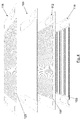
Figure 1 is a schematic view of an exemplary embodiment of a fuel cell stack showing its main elements. -
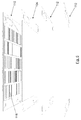
Figure 2 shows one of the bipolar plates of the fuel cell stack offigure 1 split for the inclusion of a channel according a particular embodiment. -
Figure 3 shows the two parts of the bipolar plate offigure 2 with the channel according a particular embodiment. -
Figure 4 shows a top-perspective view of an exemplary embodiment of the main layers of a fuel cell including a first layer including the channel contacting the hydrogen reaction layer. -
Figure 5 shows a bottom-perspective view of the embodiment of the main layers of the fuel cell offigure 4 . - These figures refer to the following set of elements:
- 100.
- hydrogen fuel cell stack
- 102.
- hydrogen fuel cell
- 104.
- proton exchange membrane
- 106.
- bipolar plates
- 106a, 106b
- parts of the bipolar plates
- 108.
- channel
- 110.
- first layer for the channel
- 112
- hydrogen reaction layer
- 116
- oxygen reaction layer
- 118
- distribution ducts of the hydrogen and oxygen reaction layers
- 120
- cooling grooves of the oxygen reaction layer
- The present disclosure refers to a hydrogen
fuel cell stack 100 which comprises one or morehydrogen fuel cell 102. Each one of thesehydrogen fuel cells 102 comprises in turn at least a Proton Exchange Membrane (PEM) 104, ahydrogen reaction layer 112 and anoxygen reaction layer 116 within a pair ofbipolar plates 106. The hydrogen reaction layers 112 are the anodes and the oxygen reaction layers 116 are the cathodes of thefuel cells 102. - As it can be seen in
figure 1 at least abipolar plate 106 comprises achannel 108 inside for hydrogen inflow, in order to heat up the hydrogen gas boiled off from a cryogenic liquid state at a very low temperature (about 20K) up to a usable temperature (about 273K-300K) for the fuel cell in which the hydrogen inflow enters. Thischannel 108 inside thebipolar plate 106 may have different shapes and length, and it acts as a heat exchanger, so the hydrogen inflow will be heated up before entering thehydrogen reaction layer 112, taking advantage of the heat generated in thefuel cells 102 themselves and accumulated in thebipolar plates 106, without the need for an external heating source. - This
channel 108 inside thebipolar plates 106 acting as a heat exchanger increase the hydrogen inflow temperature before reaching thehydrogen reaction layer 112. So, this heat exchanger or slim gas heating circuit increase the hydrogen inflow temperature with the minimum weight and volume increase of the overall system while using the, otherwise lost, heat dissipated by thefuel cells 102 through thebipolar plates 106, minimizing the power self-consumption of the system, therefore making it as efficient as possible. - Then, the
channel 108 of the present disclosure is a light-weight and compact heat exchanger integrated into thefuel cell 102 body, which takes advantage of the low viscosity and the great thermal conductivity of hydrogen. - Unlike existing solutions, which need a dedicated and external heat exchanger being volume and weight consuming, in the present disclosure the heat exchanger is inside the
bipolar plates 106, so the heat exchange may be considered thefuel cell 102 itself and no substantial volume increase is expected. - Moreover, since the
channel 108 or heat exchanger is located inside a heat source (the bipolar plate 106), the heat for heating up the hydrogen inflow does not need to be ducted to an external heat exchanger, avoiding fans, ducts, wiring, piping, fittings or certain valves with the corresponding weight and volume thereof. Additionally, this leads to a simpler system with many fewer components. - Another advantage of the present disclosure is that undesirable icing of the already existing solutions is avoided by heating the overcooled hydrogen inflow in a high temperature environment, as that existing in the
fuel cells 102 core, specifically the bipolar plates 106 (about 323K), being such temperature far away from the dew point of any water vapour flow that could be around. - Additionally, as the heat exchanger is enclosed inside the hydrogen
fuel cell stack 100, only clean hydrogen is in contact with thechannel 108 or heat exchanger, therefore no heat exchanger cleaning or maintenance is necessary. - Furthermore, reduced cooling of the
fuel cells 102 is needed. Since thefuel cell 102 dissipates half of the total power produced in form of heat, this heat must be removed from thecell 102 by means of the cell's cooling system as already existing. However, using some of this heat (around 10%) for a useful purpose, which is the heating of the hydrogen inflow, the cooling system requirements decrease, allowing lighter and smaller fans and less power needed for them. So, thechannel 108 provides sufficient heating of the hydrogen and useful cooling of thefuel cell 102. - Although this disclosure is specifically described here for Proton Exchange Membrane (PEM) fuel cell stacks, it can be used with any kind of fuel cells couple to a liquid hydrogen system.
-
Figures 2 and 3 show a particular embodiment in which thechannel 108 for the hydrogen inflow is engraved directly within thebipolar plate 106. Thischannel 108 or heat exchanger is machined directly within thebipolar plates 106 and no additional parts are expected, neither appreciable weight nor volume increase, since thechannel 108 is integrated into thefuel cell 102 mainly by removing material in existing parts. For such purpose thebipolar plates 106 are firstly split in twoparts channel 108 is engraved directly on one of theparts parts bipolar plate 106 with thechannel 108 inside. - Accordingly, some components such as sealing joints or some small piping will be needed, although the will add very low weight in any case and even lower when compared to an external dedicated heat exchanger.
- In this case, as the
heat exchanger channels 108 are engraved directly inside thefuel cell 102, the resulting structural integrity of the heat exchanger is even greater. - Alternatively,
figures 4 and5 show a particular embodiment in which thechannel 108 for the hydrogen inflow is made within afirst layer 110, thefirst layer 110 contacting thehydrogen reaction layer 112 or anode of thehydrogen fuel cell 102. In order to include thefirst layer 110 with thechannel 108, the depth of thebipolar plate 106 might have to be reduced. - As an alternative embodiment not shown in the figures, the
channel 108 for the hydrogen inflow is made within a second layer, the second layer contacting in this case theoxygen reaction layer 116 of thehydrogen fuel cell 102. Similarly, in order to include the second layer with thechannel 108, the depth of thebipolar plate 106 might have to be reduced. - With accord to a preferred embodiment, the
oxygen reaction layer 116 comprises a plurality of coolinggrooves 120 for the cooling of saidoxygen reaction layer 116, being the cooling fluid flowing through the coolinggrooves 120 typically air or water. - In accordance with a particular embodiment, the
hydrogen reaction layer 112 or anode comprises a plurality ofdistribution ducts 118 for the distribution of the hydrogen all along the entire surface of the Proton Exchange Membrane (PEM) 104. - According with other particular embodiment, the
oxygen reaction layer 116 or cathode has a plurality ofdistribution ducts 118 for the distribution of the oxygen all along the entire surface of the cathode, and additionally so that the entering air drags the generated water outside thefuel cell 102. - Moreover, preferably both
hydrogen reaction layer 112 andoxygen reaction layer 116 havedistribution ducts 118 for the complete distribution of hydrogen and oxygen, in order to provide a uniform reaction over the surface of the membrane. - According to an exemplary embodiment, the
channel 108 for the hydrogen inflow of the present disclosure is related to the fuel consumption of an aircraft fuel system. Since the quantity of hydrogen flow to be heated is substantially the same as the quantity of hydrogen being consumed by the cell, thechannel 108 for the hydrogen inflow has approximately the same cross-sectional area as thedistribution ducts 118 of thehydrogen reaction layer 112. More specifically, thechannel 108 and thedistribution ducts 118 are each sized such that, in operation, the quantity of hydrogen flowing through thechannel 108 is approximately equal to the quantity of hydrogen flowing through thedistribution ducts 118. - Regarding the materials, the
bipolar plates 106 are made of any electrical conductor material. According to a particular embodiment thebipolar plates 106 are made of graphite. - Additionally, the present disclosure relates to a method of upgrading a hydrogen fuel cell stack, the method comprising inserting a
channel 108 for hydrogen inflow inside at least abipolar plate 106. - According a preferred embodiment, the method comprises inserting a
first layer 110 with thechannel 108 for hydrogen inflow, thefirst layer 110 contacting thehydrogen reaction layer 112 of thehydrogen fuel cell 102. - With accord to an alternative embodiment, the method comprises inserting a second layer with the
channel 108 for hydrogen inflow, the second layer contacting in this case theoxygen reaction layer 118 of thehydrogen fuel cell 102. - Alternatively, a particular embodiment of the method comprises engraving the
channel 108 for hydrogen inflow directly within thebipolar plate 106. - For such purpose, in a first step of the method the
bipolar plates 106 are split in two parts. Then, in a second step of the method thechannel 108 is engraved directly on one of the parts or on both parts of thebipolar plate 106. Finally, in a third step both parts of the splitbipolar plate 106 are connected together again forming the bipolar plate 16 with thechannel 108 inside.
Claims (14)
- A hydrogen fuel cell stack comprising one or more hydrogen fuel cell (102) comprising a Proton Exchange Membrane (104), a hydrogen reaction layer (112) and an oxygen reaction layer (116) within a pair of bipolar plates (106), wherein at least one of the bipolar plates (106) comprises a channel (108) inside for hydrogen inflow.
- The hydrogen fuel cell stack of claim 1, wherein the channel (108) for the hydrogen inflow is made within a first layer (110), said first layer (110) contacting the hydrogen reaction layer (112) of the hydrogen fuel cell (102).
- The hydrogen fuel cell stack of claim 1, wherein the channel (108) for the hydrogen inflow is made within a second layer, said second layer contacting the oxygen reaction layer (116) of the hydrogen fuel cell (102).
- The hydrogen fuel cell stack of claim 1, wherein the channel (108) for the hydrogen inflow is engraved within the bipolar plate (106).
- The hydrogen fuel cell stack of claim 1, wherein the hydrogen reaction layer (112) comprises a plurality of distribution ducts (118).
- The hydrogen fuel cell stack of claim 1, wherein the oxygen reaction layer (116) comprises a plurality of cooling grooves (120).
- The hydrogen fuel cell stack of claim 1, wherein the oxygen reaction layer (116) comprises a plurality of distribution ducts (118).
- The hydrogen fuel cell stack of claim 5, wherein the channel (108) for the hydrogen inflow has the same section of the distribution ducts (118) of the hydrogen reaction layer (112).
- The hydrogen fuel cell stack of claim 1, wherein the bipolar plates (106) are made of graphite.
- Method of upgrading a hydrogen fuel cell stack, said method comprising inserting a channel (108) for hydrogen inflow inside at least a bipolar plate (106).
- The method of upgrading a hydrogen fuel cell stack of claim 10, said method comprising inserting a first layer (110) comprising the channel (108) for hydrogen inflow contacting the hydrogen reaction layer (112) of the hydrogen fuel cell (102).
- The method of upgrading a hydrogen fuel cell stack of claim 10, said method comprising inserting a second layer comprising the channel (108) for hydrogen inflow contacting the oxygen reaction layer (116) of the hydrogen fuel cell (102).
- The method of upgrading a hydrogen fuel cell stack of claim 10, said method comprising engraving the channel (108) for hydrogen inflow within the bipolar plate (106).
- The method of upgrading a hydrogen fuel cell stack according the previous claim, comprising a first step of splitting the bipolar plate (106) in two parts, a second step of engraving the channel (108) and a third step of connecting again both parts of the bipolar plate (106).
Priority Applications (3)
| Application Number | Priority Date | Filing Date | Title |
|---|---|---|---|
| EP16382290.1A EP3261160B1 (en) | 2016-06-23 | 2016-06-23 | Hydrogen fuel cell stack and method for upgrading a hydrogen fuel cell stack |
| ES16382290T ES2872450T3 (en) | 2016-06-23 | 2016-06-23 | Hydrogen Fuel Cell Stack and Method for Improving a Hydrogen Fuel Cell Stack |
| US15/475,782 US11276869B2 (en) | 2016-06-23 | 2017-03-31 | Hydrogen fuel cell stack and method for upgrading a hydrogen fuel cell stack |
Applications Claiming Priority (1)
| Application Number | Priority Date | Filing Date | Title |
|---|---|---|---|
| EP16382290.1A EP3261160B1 (en) | 2016-06-23 | 2016-06-23 | Hydrogen fuel cell stack and method for upgrading a hydrogen fuel cell stack |
Publications (2)
| Publication Number | Publication Date |
|---|---|
| EP3261160A1 true EP3261160A1 (en) | 2017-12-27 |
| EP3261160B1 EP3261160B1 (en) | 2021-03-17 |
Family
ID=56203293
Family Applications (1)
| Application Number | Title | Priority Date | Filing Date |
|---|---|---|---|
| EP16382290.1A Active EP3261160B1 (en) | 2016-06-23 | 2016-06-23 | Hydrogen fuel cell stack and method for upgrading a hydrogen fuel cell stack |
Country Status (3)
| Country | Link |
|---|---|
| US (1) | US11276869B2 (en) |
| EP (1) | EP3261160B1 (en) |
| ES (1) | ES2872450T3 (en) |
Cited By (2)
| Publication number | Priority date | Publication date | Assignee | Title |
|---|---|---|---|---|
| CN114175323A (en) * | 2020-05-15 | 2022-03-11 | 日产自动车株式会社 | fuel cell stack |
| CN115360376A (en) * | 2022-07-20 | 2022-11-18 | 东风汽车集团股份有限公司 | Bipolar plate, fuel cell stack and vehicle |
Families Citing this family (7)
| Publication number | Priority date | Publication date | Assignee | Title |
|---|---|---|---|---|
| MX2022000089A (en) * | 2019-06-21 | 2022-04-27 | Alakai Tech Corporation | SYSTEM, METHOD AND APPARATUS OF HIGH ENERGY DENSITY, LIGHTWEIGHT, FAULT-TOLERANT FUEL CELL FOR CLEAN-FUEL ELECTRIC AIRCRAFT. |
| CN112133948B (en) * | 2020-10-19 | 2024-12-06 | 南通百应能源有限公司 | Air-cooled atmospheric pressure open stack multi-layer single stack structure |
| CN113410501B (en) * | 2021-06-10 | 2025-01-21 | 黄冈格罗夫氢能汽车有限公司 | A hydrogen fuel cell stack |
| CN114932815B (en) * | 2022-05-19 | 2023-08-29 | 青岛同清湖氢能源科技有限公司 | Power generation power distribution method for hydrogen fuel cell electric protection car |
| CN114954961B (en) * | 2022-07-13 | 2025-03-21 | 斗山创新(深圳)有限公司 | A hydrogen fuel cell system for industrial-grade vertical take-off and landing fixed-wing UAVs |
| US12394804B2 (en) | 2022-08-16 | 2025-08-19 | General Electric Company | Thermal management of a fuel cell assembly |
| CN120727908B (en) * | 2025-08-21 | 2025-11-14 | 协氢(上海)新能源科技有限公司 | Modularized assembled hydrogen fuel cell |
Citations (4)
| Publication number | Priority date | Publication date | Assignee | Title |
|---|---|---|---|---|
| US20050244700A1 (en) * | 2004-05-03 | 2005-11-03 | Abd Elhamid Mahmoud H | Hybrid bipolar plate assembly and devices incorporating same |
| US20060240308A1 (en) * | 2005-04-22 | 2006-10-26 | Volker Formanski | Fuel cell design with an integrated heat exchanger and gas humidification unit |
| US20070003815A1 (en) * | 2005-06-30 | 2007-01-04 | General Motors Corporation | Fuel cell contact element including a TiO2 layer and a conductive layer |
| US20080176114A1 (en) * | 2007-01-23 | 2008-07-24 | Samsung Electronics Co., Ltd. | Fuel cell system and managing method thereof |
Family Cites Families (3)
| Publication number | Priority date | Publication date | Assignee | Title |
|---|---|---|---|---|
| US20090130500A1 (en) * | 2005-11-18 | 2009-05-21 | Wozniczka Boguslaw M | Method of operating a fuel cell stack at low pressure and low power conditions |
| US8563075B2 (en) * | 2007-04-04 | 2013-10-22 | GM Global Technology Operations LLC | Removal of non-conductive hydrophilic coatings from lands of fuel cell bipolar plates |
| US20160372765A1 (en) * | 2015-06-18 | 2016-12-22 | Energyor Technologies Inc | Combined fuel cell stack and heat exchanger assembly |
-
2016
- 2016-06-23 EP EP16382290.1A patent/EP3261160B1/en active Active
- 2016-06-23 ES ES16382290T patent/ES2872450T3/en active Active
-
2017
- 2017-03-31 US US15/475,782 patent/US11276869B2/en active Active
Patent Citations (4)
| Publication number | Priority date | Publication date | Assignee | Title |
|---|---|---|---|---|
| US20050244700A1 (en) * | 2004-05-03 | 2005-11-03 | Abd Elhamid Mahmoud H | Hybrid bipolar plate assembly and devices incorporating same |
| US20060240308A1 (en) * | 2005-04-22 | 2006-10-26 | Volker Formanski | Fuel cell design with an integrated heat exchanger and gas humidification unit |
| US20070003815A1 (en) * | 2005-06-30 | 2007-01-04 | General Motors Corporation | Fuel cell contact element including a TiO2 layer and a conductive layer |
| US20080176114A1 (en) * | 2007-01-23 | 2008-07-24 | Samsung Electronics Co., Ltd. | Fuel cell system and managing method thereof |
Cited By (4)
| Publication number | Priority date | Publication date | Assignee | Title |
|---|---|---|---|---|
| CN114175323A (en) * | 2020-05-15 | 2022-03-11 | 日产自动车株式会社 | fuel cell stack |
| EP4152448A4 (en) * | 2020-05-15 | 2024-01-10 | NISSAN MOTOR Co., Ltd. | STACKING FUEL CELLS |
| US12374705B2 (en) | 2020-05-15 | 2025-07-29 | Nissan Motor Co., Ltd. | Fuel cell stack |
| CN115360376A (en) * | 2022-07-20 | 2022-11-18 | 东风汽车集团股份有限公司 | Bipolar plate, fuel cell stack and vehicle |
Also Published As
| Publication number | Publication date |
|---|---|
| US20170373332A1 (en) | 2017-12-28 |
| US11276869B2 (en) | 2022-03-15 |
| ES2872450T3 (en) | 2021-11-02 |
| EP3261160B1 (en) | 2021-03-17 |
Similar Documents
| Publication | Publication Date | Title |
|---|---|---|
| EP3261160A1 (en) | Hydrogen fuel cell stack and method for upgrading a hydrogen fuel cell stack | |
| Renau et al. | Design and manufacture of a high-temperature PEMFC and its cooling system to power a lightweight UAV for a high altitude mission | |
| EP2658022B1 (en) | Warming feature for aircraft fuel cells | |
| EP2328219B1 (en) | Fuel cell system | |
| CA2900513A1 (en) | Soec stack with integrated heater | |
| EP2907185A1 (en) | Design of bipolar plates for use in conduction-cooled electrochemical cells | |
| US6682841B1 (en) | Thermal management for a vehicle mounted fuel cell system | |
| US20120177973A1 (en) | Electrochemical energy storage and method for cooling or heating an electrochemical energy storage | |
| KR102407156B1 (en) | Vapor chamber for drone fuel cell and fuel cell stack equipped with them | |
| CN100379065C (en) | Fuel cell power generation system that can start and operate in low temperature environment | |
| Saleh et al. | Environmental impact of high altitudes on the operation of PEM fuel cell based UAS | |
| CN105280988A (en) | Single-cell connector having temperature control device, battery single cell, battery module and motor vehicle | |
| CN112599813A (en) | Portable air-cooled hydrogen fuel cell system | |
| WO2024022031A1 (en) | Aircraft power battery, aircraft, and aircraft power battery integrated power supply method | |
| US11450865B2 (en) | Fuel cell system having improved gas diffusion layers and motor vehicle having a fuel cell system | |
| EP4453285A1 (en) | Solid oxide electrolysis cell core | |
| CN118434921A (en) | Solid oxide electrolytic cell core equipment | |
| JP2013069685A (en) | Power supply device | |
| EP3123546B1 (en) | Relief design for fuel cell plates | |
| JP2008108610A (en) | Fuel cell | |
| US20090023025A1 (en) | Passive Coolant Recirculation in Fuel Cells | |
| EP2891203B1 (en) | Fuel cell component having selected cooling capacity distribution | |
| US20250083824A1 (en) | Fuel cell integrated in wing leading edge | |
| JP2018186052A (en) | Fuel cell | |
| KR101683579B1 (en) | Heat recycling fuel cell module |
Legal Events
| Date | Code | Title | Description |
|---|---|---|---|
| STAA | Information on the status of an ep patent application or granted ep patent |
Free format text: STATUS: EXAMINATION IS IN PROGRESS |
|
| PUAI | Public reference made under article 153(3) epc to a published international application that has entered the european phase |
Free format text: ORIGINAL CODE: 0009012 |
|
| 17P | Request for examination filed |
Effective date: 20160623 |
|
| AK | Designated contracting states |
Kind code of ref document: A1 Designated state(s): AL AT BE BG CH CY CZ DE DK EE ES FI FR GB GR HR HU IE IS IT LI LT LU LV MC MK MT NL NO PL PT RO RS SE SI SK SM TR |
|
| AX | Request for extension of the european patent |
Extension state: BA ME |
|
| RIC1 | Information provided on ipc code assigned before grant |
Ipc: H01M 8/04007 20160101ALI20200415BHEP Ipc: H01M 8/1018 20160101ALN20200415BHEP Ipc: H01M 8/0267 20160101ALI20200415BHEP Ipc: H01M 8/0258 20160101ALI20200415BHEP Ipc: H01M 8/0213 20160101AFI20200415BHEP |
|
| GRAP | Despatch of communication of intention to grant a patent |
Free format text: ORIGINAL CODE: EPIDOSNIGR1 |
|
| STAA | Information on the status of an ep patent application or granted ep patent |
Free format text: STATUS: GRANT OF PATENT IS INTENDED |
|
| RIC1 | Information provided on ipc code assigned before grant |
Ipc: H01M 8/0213 20160101AFI20201013BHEP Ipc: H01M 8/0258 20160101ALI20201013BHEP Ipc: H01M 8/04007 20160101ALI20201013BHEP Ipc: H01M 8/1018 20160101ALN20201013BHEP Ipc: H01M 8/0267 20160101ALI20201013BHEP |
|
| RIC1 | Information provided on ipc code assigned before grant |
Ipc: H01M 8/0258 20160101ALI20201026BHEP Ipc: H01M 8/0213 20160101AFI20201026BHEP Ipc: H01M 8/0267 20160101ALI20201026BHEP Ipc: H01M 8/1018 20160101ALN20201026BHEP Ipc: H01M 8/04007 20160101ALI20201026BHEP |
|
| INTG | Intention to grant announced |
Effective date: 20201116 |
|
| GRAS | Grant fee paid |
Free format text: ORIGINAL CODE: EPIDOSNIGR3 |
|
| GRAA | (expected) grant |
Free format text: ORIGINAL CODE: 0009210 |
|
| STAA | Information on the status of an ep patent application or granted ep patent |
Free format text: STATUS: THE PATENT HAS BEEN GRANTED |
|
| AK | Designated contracting states |
Kind code of ref document: B1 Designated state(s): AL AT BE BG CH CY CZ DE DK EE ES FI FR GB GR HR HU IE IS IT LI LT LU LV MC MK MT NL NO PL PT RO RS SE SI SK SM TR |
|
| REG | Reference to a national code |
Ref country code: GB Ref legal event code: FG4D |
|
| REG | Reference to a national code |
Ref country code: CH Ref legal event code: EP |
|
| REG | Reference to a national code |
Ref country code: DE Ref legal event code: R096 Ref document number: 602016054365 Country of ref document: DE |
|
| REG | Reference to a national code |
Ref country code: IE Ref legal event code: FG4D |
|
| REG | Reference to a national code |
Ref country code: AT Ref legal event code: REF Ref document number: 1373082 Country of ref document: AT Kind code of ref document: T Effective date: 20210415 |
|
| REG | Reference to a national code |
Ref country code: LT Ref legal event code: MG9D |
|
| PG25 | Lapsed in a contracting state [announced via postgrant information from national office to epo] |
Ref country code: FI Free format text: LAPSE BECAUSE OF FAILURE TO SUBMIT A TRANSLATION OF THE DESCRIPTION OR TO PAY THE FEE WITHIN THE PRESCRIBED TIME-LIMIT Effective date: 20210317 Ref country code: HR Free format text: LAPSE BECAUSE OF FAILURE TO SUBMIT A TRANSLATION OF THE DESCRIPTION OR TO PAY THE FEE WITHIN THE PRESCRIBED TIME-LIMIT Effective date: 20210317 Ref country code: GR Free format text: LAPSE BECAUSE OF FAILURE TO SUBMIT A TRANSLATION OF THE DESCRIPTION OR TO PAY THE FEE WITHIN THE PRESCRIBED TIME-LIMIT Effective date: 20210618 Ref country code: NO Free format text: LAPSE BECAUSE OF FAILURE TO SUBMIT A TRANSLATION OF THE DESCRIPTION OR TO PAY THE FEE WITHIN THE PRESCRIBED TIME-LIMIT Effective date: 20210617 Ref country code: BG Free format text: LAPSE BECAUSE OF FAILURE TO SUBMIT A TRANSLATION OF THE DESCRIPTION OR TO PAY THE FEE WITHIN THE PRESCRIBED TIME-LIMIT Effective date: 20210617 |
|
| REG | Reference to a national code |
Ref country code: AT Ref legal event code: MK05 Ref document number: 1373082 Country of ref document: AT Kind code of ref document: T Effective date: 20210317 |
|
| REG | Reference to a national code |
Ref country code: NL Ref legal event code: MP Effective date: 20210317 |
|
| PG25 | Lapsed in a contracting state [announced via postgrant information from national office to epo] |
Ref country code: SE Free format text: LAPSE BECAUSE OF FAILURE TO SUBMIT A TRANSLATION OF THE DESCRIPTION OR TO PAY THE FEE WITHIN THE PRESCRIBED TIME-LIMIT Effective date: 20210317 Ref country code: LV Free format text: LAPSE BECAUSE OF FAILURE TO SUBMIT A TRANSLATION OF THE DESCRIPTION OR TO PAY THE FEE WITHIN THE PRESCRIBED TIME-LIMIT Effective date: 20210317 Ref country code: RS Free format text: LAPSE BECAUSE OF FAILURE TO SUBMIT A TRANSLATION OF THE DESCRIPTION OR TO PAY THE FEE WITHIN THE PRESCRIBED TIME-LIMIT Effective date: 20210317 |
|
| PG25 | Lapsed in a contracting state [announced via postgrant information from national office to epo] |
Ref country code: NL Free format text: LAPSE BECAUSE OF FAILURE TO SUBMIT A TRANSLATION OF THE DESCRIPTION OR TO PAY THE FEE WITHIN THE PRESCRIBED TIME-LIMIT Effective date: 20210317 |
|
| PG25 | Lapsed in a contracting state [announced via postgrant information from national office to epo] |
Ref country code: LT Free format text: LAPSE BECAUSE OF FAILURE TO SUBMIT A TRANSLATION OF THE DESCRIPTION OR TO PAY THE FEE WITHIN THE PRESCRIBED TIME-LIMIT Effective date: 20210317 Ref country code: EE Free format text: LAPSE BECAUSE OF FAILURE TO SUBMIT A TRANSLATION OF THE DESCRIPTION OR TO PAY THE FEE WITHIN THE PRESCRIBED TIME-LIMIT Effective date: 20210317 Ref country code: CZ Free format text: LAPSE BECAUSE OF FAILURE TO SUBMIT A TRANSLATION OF THE DESCRIPTION OR TO PAY THE FEE WITHIN THE PRESCRIBED TIME-LIMIT Effective date: 20210317 Ref country code: SM Free format text: LAPSE BECAUSE OF FAILURE TO SUBMIT A TRANSLATION OF THE DESCRIPTION OR TO PAY THE FEE WITHIN THE PRESCRIBED TIME-LIMIT Effective date: 20210317 Ref country code: AT Free format text: LAPSE BECAUSE OF FAILURE TO SUBMIT A TRANSLATION OF THE DESCRIPTION OR TO PAY THE FEE WITHIN THE PRESCRIBED TIME-LIMIT Effective date: 20210317 |
|
| REG | Reference to a national code |
Ref country code: ES Ref legal event code: FG2A Ref document number: 2872450 Country of ref document: ES Kind code of ref document: T3 Effective date: 20211102 |
|
| PG25 | Lapsed in a contracting state [announced via postgrant information from national office to epo] |
Ref country code: SK Free format text: LAPSE BECAUSE OF FAILURE TO SUBMIT A TRANSLATION OF THE DESCRIPTION OR TO PAY THE FEE WITHIN THE PRESCRIBED TIME-LIMIT Effective date: 20210317 Ref country code: RO Free format text: LAPSE BECAUSE OF FAILURE TO SUBMIT A TRANSLATION OF THE DESCRIPTION OR TO PAY THE FEE WITHIN THE PRESCRIBED TIME-LIMIT Effective date: 20210317 Ref country code: PL Free format text: LAPSE BECAUSE OF FAILURE TO SUBMIT A TRANSLATION OF THE DESCRIPTION OR TO PAY THE FEE WITHIN THE PRESCRIBED TIME-LIMIT Effective date: 20210317 Ref country code: PT Free format text: LAPSE BECAUSE OF FAILURE TO SUBMIT A TRANSLATION OF THE DESCRIPTION OR TO PAY THE FEE WITHIN THE PRESCRIBED TIME-LIMIT Effective date: 20210719 Ref country code: IS Free format text: LAPSE BECAUSE OF FAILURE TO SUBMIT A TRANSLATION OF THE DESCRIPTION OR TO PAY THE FEE WITHIN THE PRESCRIBED TIME-LIMIT Effective date: 20210717 |
|
| REG | Reference to a national code |
Ref country code: DE Ref legal event code: R097 Ref document number: 602016054365 Country of ref document: DE |
|
| PLBE | No opposition filed within time limit |
Free format text: ORIGINAL CODE: 0009261 |
|
| STAA | Information on the status of an ep patent application or granted ep patent |
Free format text: STATUS: NO OPPOSITION FILED WITHIN TIME LIMIT |
|
| PG25 | Lapsed in a contracting state [announced via postgrant information from national office to epo] |
Ref country code: AL Free format text: LAPSE BECAUSE OF FAILURE TO SUBMIT A TRANSLATION OF THE DESCRIPTION OR TO PAY THE FEE WITHIN THE PRESCRIBED TIME-LIMIT Effective date: 20210317 Ref country code: MC Free format text: LAPSE BECAUSE OF FAILURE TO SUBMIT A TRANSLATION OF THE DESCRIPTION OR TO PAY THE FEE WITHIN THE PRESCRIBED TIME-LIMIT Effective date: 20210317 Ref country code: DK Free format text: LAPSE BECAUSE OF FAILURE TO SUBMIT A TRANSLATION OF THE DESCRIPTION OR TO PAY THE FEE WITHIN THE PRESCRIBED TIME-LIMIT Effective date: 20210317 |
|
| REG | Reference to a national code |
Ref country code: CH Ref legal event code: PL |
|
| 26N | No opposition filed |
Effective date: 20211220 |
|
| PG25 | Lapsed in a contracting state [announced via postgrant information from national office to epo] |
Ref country code: SI Free format text: LAPSE BECAUSE OF FAILURE TO SUBMIT A TRANSLATION OF THE DESCRIPTION OR TO PAY THE FEE WITHIN THE PRESCRIBED TIME-LIMIT Effective date: 20210317 |
|
| REG | Reference to a national code |
Ref country code: BE Ref legal event code: MM Effective date: 20210630 |
|
| PG25 | Lapsed in a contracting state [announced via postgrant information from national office to epo] |
Ref country code: LU Free format text: LAPSE BECAUSE OF NON-PAYMENT OF DUE FEES Effective date: 20210623 |
|
| PG25 | Lapsed in a contracting state [announced via postgrant information from national office to epo] |
Ref country code: LI Free format text: LAPSE BECAUSE OF NON-PAYMENT OF DUE FEES Effective date: 20210630 Ref country code: IT Free format text: LAPSE BECAUSE OF FAILURE TO SUBMIT A TRANSLATION OF THE DESCRIPTION OR TO PAY THE FEE WITHIN THE PRESCRIBED TIME-LIMIT Effective date: 20210317 Ref country code: IE Free format text: LAPSE BECAUSE OF NON-PAYMENT OF DUE FEES Effective date: 20210623 Ref country code: CH Free format text: LAPSE BECAUSE OF NON-PAYMENT OF DUE FEES Effective date: 20210630 |
|
| PG25 | Lapsed in a contracting state [announced via postgrant information from national office to epo] |
Ref country code: IS Free format text: LAPSE BECAUSE OF FAILURE TO SUBMIT A TRANSLATION OF THE DESCRIPTION OR TO PAY THE FEE WITHIN THE PRESCRIBED TIME-LIMIT Effective date: 20210717 |
|
| PG25 | Lapsed in a contracting state [announced via postgrant information from national office to epo] |
Ref country code: BE Free format text: LAPSE BECAUSE OF NON-PAYMENT OF DUE FEES Effective date: 20210630 |
|
| PG25 | Lapsed in a contracting state [announced via postgrant information from national office to epo] |
Ref country code: HU Free format text: LAPSE BECAUSE OF FAILURE TO SUBMIT A TRANSLATION OF THE DESCRIPTION OR TO PAY THE FEE WITHIN THE PRESCRIBED TIME-LIMIT; INVALID AB INITIO Effective date: 20160623 |
|
| P01 | Opt-out of the competence of the unified patent court (upc) registered |
Effective date: 20230516 |
|
| PG25 | Lapsed in a contracting state [announced via postgrant information from national office to epo] |
Ref country code: CY Free format text: LAPSE BECAUSE OF FAILURE TO SUBMIT A TRANSLATION OF THE DESCRIPTION OR TO PAY THE FEE WITHIN THE PRESCRIBED TIME-LIMIT Effective date: 20210317 |
|
| PG25 | Lapsed in a contracting state [announced via postgrant information from national office to epo] |
Ref country code: MK Free format text: LAPSE BECAUSE OF FAILURE TO SUBMIT A TRANSLATION OF THE DESCRIPTION OR TO PAY THE FEE WITHIN THE PRESCRIBED TIME-LIMIT Effective date: 20210317 |
|
| PG25 | Lapsed in a contracting state [announced via postgrant information from national office to epo] |
Ref country code: TR Free format text: LAPSE BECAUSE OF FAILURE TO SUBMIT A TRANSLATION OF THE DESCRIPTION OR TO PAY THE FEE WITHIN THE PRESCRIBED TIME-LIMIT Effective date: 20210317 |
|
| PG25 | Lapsed in a contracting state [announced via postgrant information from national office to epo] |
Ref country code: MT Free format text: LAPSE BECAUSE OF FAILURE TO SUBMIT A TRANSLATION OF THE DESCRIPTION OR TO PAY THE FEE WITHIN THE PRESCRIBED TIME-LIMIT Effective date: 20210317 |
|
| PGFP | Annual fee paid to national office [announced via postgrant information from national office to epo] |
Ref country code: DE Payment date: 20250627 Year of fee payment: 10 |
|
| PGFP | Annual fee paid to national office [announced via postgrant information from national office to epo] |
Ref country code: GB Payment date: 20250627 Year of fee payment: 10 |
|
| PGFP | Annual fee paid to national office [announced via postgrant information from national office to epo] |
Ref country code: FR Payment date: 20250625 Year of fee payment: 10 |
|
| PGFP | Annual fee paid to national office [announced via postgrant information from national office to epo] |
Ref country code: ES Payment date: 20250701 Year of fee payment: 10 |