EP3261072B1 - Heat detector - Google Patents
Heat detector Download PDFInfo
- Publication number
- EP3261072B1 EP3261072B1 EP17174387.5A EP17174387A EP3261072B1 EP 3261072 B1 EP3261072 B1 EP 3261072B1 EP 17174387 A EP17174387 A EP 17174387A EP 3261072 B1 EP3261072 B1 EP 3261072B1
- Authority
- EP
- European Patent Office
- Prior art keywords
- heat
- sensor
- mounting panel
- sensor mounting
- sensing module
- Prior art date
- Legal status (The legal status is an assumption and is not a legal conclusion. Google has not performed a legal analysis and makes no representation as to the accuracy of the status listed.)
- Active
Links
Images







Classifications
-
- G—PHYSICS
- G08—SIGNALLING
- G08B—SIGNALLING SYSTEMS, e.g. PERSONAL CALLING SYSTEMS; ORDER TELEGRAPHS; ALARM SYSTEMS
- G08B17/00—Fire alarms; Alarms responsive to explosion
- G08B17/06—Electric actuation of the alarm, e.g. using a thermally-operated switch
-
- G—PHYSICS
- G01—MEASURING; TESTING
- G01J—MEASUREMENT OF INTENSITY, VELOCITY, SPECTRAL CONTENT, POLARISATION, PHASE OR PULSE CHARACTERISTICS OF INFRARED, VISIBLE OR ULTRAVIOLET LIGHT; COLORIMETRY; RADIATION PYROMETRY
- G01J5/00—Radiation pyrometry, e.g. infrared or optical thermometry
- G01J5/02—Constructional details
- G01J5/0205—Mechanical elements; Supports for optical elements
-
- G—PHYSICS
- G01—MEASURING; TESTING
- G01J—MEASUREMENT OF INTENSITY, VELOCITY, SPECTRAL CONTENT, POLARISATION, PHASE OR PULSE CHARACTERISTICS OF INFRARED, VISIBLE OR ULTRAVIOLET LIGHT; COLORIMETRY; RADIATION PYROMETRY
- G01J5/00—Radiation pyrometry, e.g. infrared or optical thermometry
- G01J5/02—Constructional details
- G01J5/04—Casings
- G01J5/041—Mountings in enclosures or in a particular environment
-
- G—PHYSICS
- G01—MEASURING; TESTING
- G01J—MEASUREMENT OF INTENSITY, VELOCITY, SPECTRAL CONTENT, POLARISATION, PHASE OR PULSE CHARACTERISTICS OF INFRARED, VISIBLE OR ULTRAVIOLET LIGHT; COLORIMETRY; RADIATION PYROMETRY
- G01J5/00—Radiation pyrometry, e.g. infrared or optical thermometry
- G01J5/02—Constructional details
- G01J5/08—Optical arrangements
- G01J5/0853—Optical arrangements having infrared absorbers other than the usual absorber layers deposited on infrared detectors like bolometers, wherein the heat propagation between the absorber and the detecting element occurs within a solid
-
- G—PHYSICS
- G01—MEASURING; TESTING
- G01J—MEASUREMENT OF INTENSITY, VELOCITY, SPECTRAL CONTENT, POLARISATION, PHASE OR PULSE CHARACTERISTICS OF INFRARED, VISIBLE OR ULTRAVIOLET LIGHT; COLORIMETRY; RADIATION PYROMETRY
- G01J5/00—Radiation pyrometry, e.g. infrared or optical thermometry
- G01J5/10—Radiation pyrometry, e.g. infrared or optical thermometry using electric radiation detectors
- G01J5/20—Radiation pyrometry, e.g. infrared or optical thermometry using electric radiation detectors using resistors, thermistors or semiconductors sensitive to radiation, e.g. photoconductive devices
-
- G—PHYSICS
- G08—SIGNALLING
- G08B—SIGNALLING SYSTEMS, e.g. PERSONAL CALLING SYSTEMS; ORDER TELEGRAPHS; ALARM SYSTEMS
- G08B17/00—Fire alarms; Alarms responsive to explosion
-
- G—PHYSICS
- G08—SIGNALLING
- G08B—SIGNALLING SYSTEMS, e.g. PERSONAL CALLING SYSTEMS; ORDER TELEGRAPHS; ALARM SYSTEMS
- G08B17/00—Fire alarms; Alarms responsive to explosion
- G08B17/10—Actuation by presence of smoke or gases, e.g. automatic alarm devices for analysing flowing fluid materials by the use of optical means
Definitions
- the present invention relates to a heat alarm device.
- Heat alarm devices for sensing heat, for example from a fire, are well known in the art.
- heat alarms comprise a body containing control and drive circuitry, a heat sensor extending from the body and a cage located around the heat sensor in a manner that allows free flow of air past the sensor.
- the cage is rigid and is typically made of such a size that it stands well clear of the sensor such that its thermal mass has minimum impact on the response of the sensor to a rise in ambient temperature.
- the cage is necessary to present the heat sensor at a position removed from the large thermal mass of the electronics and body of the alarm, whilst also protecting the heat sensor from damage, and preventing the sensor (which will be attached to a source of electricity) being accidentally touched by anyone.
- the sensor is generally centrally located so that the effect of the thermal mass of the body is substantially equal irrespective of the direction from which the heat originates (e.g. there is no heat shadow created by off-setting the sensor) and the protective cages are generally quite large relative to the sensor so that air can freely circulate around the sensor.
- JP2002352346A discloses a fire sensor capable of reducing effect of stray light.
- WO2012/123796 discloses a fire sensor provided with labyrinth walls defining a smoke sensing space.
- JP2011192244A discloses a heat sensor for measuring temperature quickly and accurately.
- EP1253566A2 discloses a fire detector unit having a plastic base defining a smoke chamber for detection of a smoke density in terms of light scattering due to the smoke particles in the smoke chamber.
- a heat alarm apparatus comprising a heat sensing module, the heat sensing module comprising:a housing defining a body; a sensor mounting panel having a concave reflective surface, the sensor mounting panel being recessed within the housing; a heat sensor extending from the sensor mounting panel; protection means protecting the heat sensor from damage and located around the heat sensor in a manner that allows free flow of air past the sensor; and a control circuit configured to detect a temperature rise at the heat sensor and output an alarm signal in response thereto; wherein a sensing part of the heat sensor is located in a space formed between the concave surface of the sensor mounting panel and the protection means, and, the heat sensor is located substantially central with respect to the sensor mounting panel in order that heat reflected by the concave reflective surface of the sensor mounting panel is reflected in the direction of the heat sensor.
- the colour of the surface of the sensor mounting panel is either neutral, or has a hue ranging from purple to green, and has a value of 3 or less on the Munsell Colour System. More preferably the colour of said surface of the sensor mounting panel may have a value of 2 or less, or of 1 or less, on the Munsell Colour System.
- the response time of the sensor to a change in heat of the environment in which it is placed is increased so that the alarm can indicate a danger in a quicker response time.
- the surface of the sensor mounting panel from which the heat sensor extends may optionally be provided with a plurality of embossed or impressed features thereon.
- the plurality of embossed or impressed features may comprise a plurality of pyramid shaped features extending from the surface or a plurality of pyramid shaped impressions extending into the surface, however other shapes may be used.
- having a plurality of angular shaped protrusions or recesses will increase the area of the mounting panel for which the angle of sight to the heat source, and therefore the angle of incidence of the radiated heat, is increased which will improve the heat absorption/radiation from the mounting panel.
- the sensor mounting panel is concave. Again this is believed to assist with the reflected, radiated and absorbed heat, which together increase the speed at which the heat sensor registers a change in temperature. Additionally, having a concave sensor means that a greater portion of the reflected and radiated heat will be reflected/radiated in the direction of the heat sensor which is located substantially in the centre of the sensor mounting panel.
- the sensor mounting panel comprises a moulding of a coloured plastic, or alternatively the sensor mounting panel may have a coloured coating (e.g. a paint) thereon.
- a coloured coating e.g. a paint
- a protective cage preferably extends from the housing and forms an enclosure between the protective cage and the sensor mounting panel, and the heat sensor is located in said enclosure.
- the heat sensor extends from the mounting panel, and needs free air from the environment in which it is placed to circulate around it, the purpose of the cage is twofold. Firstly it protects the heat sensor from damage, and secondly it contributes to the electrical safety of the alarm by assisting in preventing fingers or the like from coming into contact with the sensor.
- the sensor mounting panel is recessed in the housing, this assists in contributing to the protection of the sensor therein.
- the heat alarm has a heat sensor 12, which is for example a thermistor that in use detects a change in the temperature of the environment in which the alarm apparatus is located and sounds an alarm via a speaker 14 to indicate a change in temperature.
- the alarm may be used for detecting a fire.
- the housing body 16 is attached to a base 300 (see Figure 10 ).
- the alarm has a body 16 that encloses electronic circuitry 34 for powering the sensor 12 and emitting an alarm via the speaker 14 in response to a detected heat change.
- the electronic circuitry can raise the alarm based on a predefined temperature being sensed, on a rate of temperature rise being sensed, a combination of the two, or any other temperature detection or change criteria known in the art and useful as an indicator of a fire.
- the body 16 has a recess 18 in the middle in which a sensing module 20 is received.
- the sensing module has a base section 22 and a protection means 24 which together define an enclosure in which the sensor 12 is located.
- the base 22 has a hole therein through which the sensor 12 projects into the enclosure.
- the protection means 24 comprises a solid central part 26 which has a concave surface of around 2cm in diameter, and a plurality of cage like ribs 28 extending therefrom to form a cage like structure.
- air can freely pass between the ribs 28 so that the sensor 12 can detect changes in the air temperature.
- the spring clips 30 locate in channels 38 provided in the recess 18 in a manner that restricts maximum movement but allows for limited movement within the recess 18 in the direction of the channels 38.
- the heat sensor 12 is attached to a circuit board 32, which clips to the bottom of the bottom of the base section 22 by clip 36 and forms part of the sensing module.
- the circuit board 32 forms part of the sensing module 20.
- the springs 40 comprise a small boss attached to a cantilever spring which is formed as part of the same plastics moulding as the body 16. Three springs 40 are positioned symmetrically in the recess 18 so that an even biasing force is provided on the sensing module 20, although it will be appreciated that different types or numbers of springs may be used providing that a sufficient biasing force is provided on the sensing module to return it to an extended position after deformation.
- An interior surface 22A of the base 22 is provided with a surface texture thereon comprising a plurality of raised square based pyramids which increases the surface area of the base and in particular increases the angle at which radiant heat entering into the enclosure will impinge upon the interior surface 22A. This beneficially decreases the response time of the sensor 12 located within the sensing module.
- At least the interior surface of the base 22 from which the heat sensor 12 extends is a dark colour.
- dark it is meant that it's colour is either neutral (i.e. greyscale) or has a hue ranging from purple to green, and also that it has a value of 3 or less on the Munsell Colour System. The darker the colour the better the response so it will be appreciated that colours having a hue of 2, or 1 on the Munsell Colour System are preferable.
- a black surface may be used.
- At least the interior surface of the base 22 may be painted a dark colour.
- the base 22 may be moulded out of a dark, for example a black, polymer material. The effect of this is described below in relation to Figure 6 .
- buttons actuator leaf spring 42 which has an actuator extension 44 depending therefrom which is aligned so as to be positioned adjacent and spaced from a test/reset button 46 on the electronic circuitry 34.
- the base section 22 of the sensing module 20 is provided with actuator fingers 48 which extend through the circuit board 32 so that when the sensing module is depressed against the springs 40 so that it moves towards the body 16, the actuator fingers 48 press on the button actuator leaf spring 42 which in turn deflects to press on the test/reset button 46.
- the heat detector is provided with a large sensing module which includes the protection means or cage 24 to protect the heat sensor, and which large sensing module also doubles up as the test/reset button.
- the concave surface facilitates the pressing with a stick, which will often have a convex rounded end. This greatly facilitates the ease with which a person with restricted mobility can use the device as it reduces the necessity for the user to climb steps or a chair to reach the small offset test/reset button of previous designs.
- a large button can be achieved without having to increase the size of the rest of the device and which enables a large button to be used without disturbing the alarm symmetry which is beneficial in reducing heat shadow effects that would occur if a similar style button were placed alongside the heat sensor of current designs of heat detector alarm apparatus.
- the side of the base section 22 facing the heat sensor 12 is provided with a surface texture that, in the example shown, comprises a plurality of shallow pyramids which in this embodiment are square based pyramids, although it will be appreciated that other surface textures or other pyramids having a different shaped base may be used.
- a raised surface texture it will be appreciated that the features could also be other shapes, for example raised domes, or alternatively may be embossed into the surface.
- the surface of the pyramids is preferably a dark matt colour, for example matt black. It has been shown that using these geometries and using a dark matt surface can increase the response time of the temperature sensor as shown in Figure 6 . Under identical test conditions the temperature measured by the thermistor 12 was recorded over time as the external temperature was increased.
- FIG. 11 to 14 an embodiment 200 of the invention is shown. This embodiment differs from the examples shown in Figures 1 to 5 in that the sensing module 220 is mounted in the housing body 216 in a different manner. It will be appreciated that the parts shown in Figures 12 , 13 and 14 only show one half of the body housing and in practice a lower part would also be provided to enclose the interior space of the alarm as shown in Figures 1-10 .
- the sensing module 220 which comprises four parts, a protective cage 224, a base section 222 that has thereon a concave reflective surface (see Figure 11 ) which may optionally be provided with an array of surface features, for example square based prisms, a circuit board 232, and a heat sensor 212.
- the base section 222 is provided with one or more hole 256 through which electrical connectors of the heat sensor 212 can pass so that, when assembled, the sensing part of the heat sensor 212 is located in a space formed between the concave surface of the base section 222 and the protective cage or protection means 224, and the electrical connectors thereof pass through the holes 256 in the base section so that they can make electrical contact with the circuit board 232 on the other side thereof.
- the base section has extensions 258 thereon which are received in recesses 260 of the protective cage 224 and locate the two parts in rotational alignment.
- the protective cage 224 has one or more spring clips 230 thereon that are resiliently displaced as the two parts are brought together and which spring back into position to retain the base section 222 when the parts are fully brought together.
- the protection means 224 comprises a solid central part 226 which has a concave surface of at least 2cm diameter, and a plurality of cage like ribs 228 extending therefrom to form a cage like structure. These components together form the assembled sensor module 220.
- the housing body 216 has a recessed portion 218 which receives the sensing module 220.
- the recess has a lower surface 262 that is resiliently retained by the housing body 216 by a plurality of leaf type springs 240 located around the recessed portion 218, and which are each attached at one end 240A to the housing body 216 and at the other end 240B to the lower surface 262.
- the lower surface 262 is resiliently retained within the recess 218 in a manner such that a force applied thereto along the direction of the central axis of the recess will move the lower surface 262 in that direction, and when the moving force is removed the lower surface will resiliently return to its original position.
- the lower surface 262 is circular and has a sidewall therearound. Spaced around the sidewall 264 are a number of stepped features at which the height of the sidewall is stepped down to a first reduced height 266 and is then further stepped down to a second reduced height 268. These stepped sections are spaced to coincide with the extensions 258 when the sensing module 220 is located in the recess 218. Aligned with the second step 266, and attached to the sidewalls 270, are a plurality of protrusions 272 located radially outside of, and adjacent to, the sidewall 264. In its natural position, i.e. the position in which the springs are not deformed, the vertical distance between top of the first stepped feature 266 and the lower surface of the protrusion 272 is less than the thickness of the extensions 258 of the sensing module 220.
- the sensor module 220 is inserted into the recess with the protrusions 258 aligned with the first recessed steps 266.
- the sensing module is then pressed into the recess to deform the springs 240 and thereby increase the vertical distance between the top of the first recessed steps 266 and the bottom surface of the protrusions 272 such that it is greater than the thickness of the extensions 258 of the sensing module 220.
- the sensing module 220 is then rotated to move the extensions 258 thereof in alignment with the second recessed steps 268, and is then released.
- the sensing module 220 is therefore securely retained in the recess and cannot easily be removed without disassembling the heat detector.
- the housing will contain electronic circuitry to power and control the alarm device.
- a switch post 244 extends from the bottom of the lower surface 262 and operates in a similar manner to that described in relation to the extension 44 shown in Figure 4 , i.e. when the sensing module is pressed the extension 244 presses on a switch in a circuit board within the housing.
- All embodiments of the invention will usually be attached to a ceiling in a property, although they may be attached to a wall.
- a mounting plate 300 as shown in Figure 10 is shown.
- the mounting plate 300 is provided with fixing holes 302 by which it can be attached to a wall or other surface, and the alarm is provided with clips 54, 154 by which it is attached to the mounting plate 300.
Landscapes
- Physics & Mathematics (AREA)
- General Physics & Mathematics (AREA)
- Business, Economics & Management (AREA)
- Emergency Management (AREA)
- Spectroscopy & Molecular Physics (AREA)
- Chemical & Material Sciences (AREA)
- Analytical Chemistry (AREA)
- Fire-Detection Mechanisms (AREA)
- Fire Alarms (AREA)
Description
- The present invention relates to a heat alarm device.
- Heat alarm devices for sensing heat, for example from a fire, are well known in the art. Typically such heat alarms comprise a body containing control and drive circuitry, a heat sensor extending from the body and a cage located around the heat sensor in a manner that allows free flow of air past the sensor. The cage is rigid and is typically made of such a size that it stands well clear of the sensor such that its thermal mass has minimum impact on the response of the sensor to a rise in ambient temperature. The cage is necessary to present the heat sensor at a position removed from the large thermal mass of the electronics and body of the alarm, whilst also protecting the heat sensor from damage, and preventing the sensor (which will be attached to a source of electricity) being accidentally touched by anyone.
- The sensor is generally centrally located so that the effect of the thermal mass of the body is substantially equal irrespective of the direction from which the heat originates (e.g. there is no heat shadow created by off-setting the sensor) and the protective cages are generally quite large relative to the sensor so that air can freely circulate around the sensor.
-
JP2002352346A WO2012/123796 discloses a fire sensor provided with labyrinth walls defining a smoke sensing space.JP2011192244A EP1253566A2 discloses a fire detector unit having a plastic base defining a smoke chamber for detection of a smoke density in terms of light scattering due to the smoke particles in the smoke chamber. - The scope of the invention is defined by the appended claims.
- According to the embodiments of the invention there is provided a heat alarm apparatus comprising a heat sensing module, the heat sensing module comprising:a housing defining a body; a sensor mounting panel having a concave reflective surface, the sensor mounting panel being recessed within the housing;a heat sensor extending from the sensor mounting panel; protection means protecting the heat sensor from damage and located around the heat sensor in a manner that allows free flow of air past the sensor; and a control circuit configured to detect a temperature rise at the heat sensor and output an alarm signal in response thereto;wherein a sensing part of the heat sensor is located in a space formed between the concave surface of the sensor mounting panel and the protection means, and, the heat sensor is located substantially central with respect to the sensor mounting panel in order that heat reflected by the concave reflective surface of the sensor mounting panel is reflected in the direction of the heat sensor.
- In a preferred arrangement the colour of the surface of the sensor mounting panel is either neutral, or has a hue ranging from purple to green, and has a value of 3 or less on the Munsell Colour System. More preferably the colour of said surface of the sensor mounting panel may have a value of 2 or less, or of 1 or less, on the Munsell Colour System.
- By maintaining a dark colour for the surface the response time of the sensor to a change in heat of the environment in which it is placed, either radiated heat from a nearby heat source or of the air temperature, is increased so that the alarm can indicate a danger in a quicker response time.
- The surface of the sensor mounting panel from which the heat sensor extends may optionally be provided with a plurality of embossed or impressed features thereon. The plurality of embossed or impressed features may comprise a plurality of pyramid shaped features extending from the surface or a plurality of pyramid shaped impressions extending into the surface, however other shapes may be used. As, in the case of a fire, the heat is likely to come from a specific direction, then having a plurality of angular shaped protrusions or recesses will increase the area of the mounting panel for which the angle of sight to the heat source, and therefore the angle of incidence of the radiated heat, is increased which will improve the heat absorption/radiation from the mounting panel. It is also believed that the surface features may increase heat transfer when air passes thereover. The effect is measureable and demonstrable and although the mechanics of the benefit described herein are believed to be accurate they have not been irrefutably proven and the effect may be for reasons other than those stated.
- According to the invention the sensor mounting panel is concave. Again this is believed to assist with the reflected, radiated and absorbed heat, which together increase the speed at which the heat sensor registers a change in temperature. Additionally, having a concave sensor means that a greater portion of the reflected and radiated heat will be reflected/radiated in the direction of the heat sensor which is located substantially in the centre of the sensor mounting panel.
- The sensor mounting panel comprises a moulding of a coloured plastic, or alternatively the sensor mounting panel may have a coloured coating (e.g. a paint) thereon.
- A protective cage preferably extends from the housing and forms an enclosure between the protective cage and the sensor mounting panel, and the heat sensor is located in said enclosure. As the heat sensor extends from the mounting panel, and needs free air from the environment in which it is placed to circulate around it, the purpose of the cage is twofold. Firstly it protects the heat sensor from damage, and secondly it contributes to the electrical safety of the alarm by assisting in preventing fingers or the like from coming into contact with the sensor.
- The sensor mounting panel is recessed in the housing, this assists in contributing to the protection of the sensor therein.
- Specific embodiments of the invention and examples not falling under the scope of the invention are described below, by way of example, with reference to the drawings, in which:
-
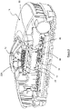
Figure 1 shows a perspective view of a first example not falling under the scope of the invention of a heat alarm apparatus; -
Figure 2 shows a partially exploded view of the heat alarm ofFigure 1 ; -
Figure 3 shows a section view of the heat alarm ofFigure 1 ; -
Figure 4 shows an exploded section view of the alarm ofFigure 1 ; -
Figure 5 shows a perspective view of the top of the alarm ofFigure 1 with the sensing module omitted; -
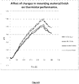
Figure 6 shows the response times of the alarm ofFigure 1 with different specifications for the sensor mounting panel; -
Figure 7 shows an exploded section view of the heat sensing module; -
Figure 8 shows a section view of the heat sensing module; -
Figure 9 shows a perspective view of the assembled heat sensing module ; -
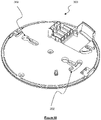
Figure 10 shows a mounting plate for the alarm apparatus of the invention; -
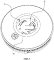
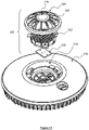
Figure 11 shows an exploded view of an embodiment of the invention; -
Figure 12 shows a perspective view of the top of the housing body of the embodiment of the invention; -
Figure 13 shows a perspective view of the bottom of the housing body of the embodiment of the invention; and -
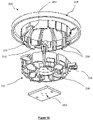
Figure 14 shows an exploded view of the sensor button assembly of the embodiment of the invention. - Referring to
Figures 1 to 9 aheat alarm apparatus 10 is shown. The heat alarm has aheat sensor 12, which is for example a thermistor that in use detects a change in the temperature of the environment in which the alarm apparatus is located and sounds an alarm via aspeaker 14 to indicate a change in temperature. The alarm may be used for detecting a fire. Thehousing body 16 is attached to a base 300 (seeFigure 10 ). - The alarm has a
body 16 that encloseselectronic circuitry 34 for powering thesensor 12 and emitting an alarm via thespeaker 14 in response to a detected heat change. The electronic circuitry can raise the alarm based on a predefined temperature being sensed, on a rate of temperature rise being sensed, a combination of the two, or any other temperature detection or change criteria known in the art and useful as an indicator of a fire. - The
body 16 has arecess 18 in the middle in which asensing module 20 is received. The sensing module has abase section 22 and a protection means 24 which together define an enclosure in which thesensor 12 is located. Thebase 22 has a hole therein through which thesensor 12 projects into the enclosure. The protection means 24 comprises a solidcentral part 26 which has a concave surface of around 2cm in diameter, and a plurality of cage likeribs 28 extending therefrom to form a cage like structure. - In use air can freely pass between the
ribs 28 so that thesensor 12 can detect changes in the air temperature. - The
base section 22 and the protection means 24, or cage, clip together forming the enclosure, which is provided withspring clips 30 on its outer surface. Although shown attached to the protection means 24 it will be appreciated that thespring clips 30 may be provided on thebase 22. - The
spring clips 30 locate inchannels 38 provided in therecess 18 in a manner that restricts maximum movement but allows for limited movement within therecess 18 in the direction of thechannels 38. - The
heat sensor 12 is attached to acircuit board 32, which clips to the bottom of the bottom of thebase section 22 byclip 36 and forms part of the sensing module. Thecircuit board 32 forms part of thesensing module 20. - In this manner the
entire sensing module 20 can slide in therecess 18.Springs 40 bias the sensing module into an outermost position in which thesensing module 20 is extended at a maximum position from thebody 16 and wherein pressure on the protection means 24 in a direction towards the recess will cause the sensing module to move within thechannels 38 against the bias of the springs. - The
springs 40 comprise a small boss attached to a cantilever spring which is formed as part of the same plastics moulding as thebody 16. Threesprings 40 are positioned symmetrically in therecess 18 so that an even biasing force is provided on thesensing module 20, although it will be appreciated that different types or numbers of springs may be used providing that a sufficient biasing force is provided on the sensing module to return it to an extended position after deformation. - An
interior surface 22A of thebase 22 is provided with a surface texture thereon comprising a plurality of raised square based pyramids which increases the surface area of the base and in particular increases the angle at which radiant heat entering into the enclosure will impinge upon theinterior surface 22A. This beneficially decreases the response time of thesensor 12 located within the sensing module. - At least the interior surface of the base 22 from which the
heat sensor 12 extends is a dark colour. By dark it is meant that it's colour is either neutral (i.e. greyscale) or has a hue ranging from purple to green, and also that it has a value of 3 or less on the Munsell Colour System. The darker the colour the better the response so it will be appreciated that colours having a hue of 2, or 1 on the Munsell Colour System are preferable. In particular a black surface may be used. At least the interior surface of the base 22 may be painted a dark colour. Alternatively the base 22 may be moulded out of a dark, for example a black, polymer material. The effect of this is described below in relation toFigure 6 . - Also provided in the
recess 18 is a buttonactuator leaf spring 42 which has anactuator extension 44 depending therefrom which is aligned so as to be positioned adjacent and spaced from a test/reset button 46 on theelectronic circuitry 34. - The
base section 22 of thesensing module 20 is provided withactuator fingers 48 which extend through thecircuit board 32 so that when the sensing module is depressed against thesprings 40 so that it moves towards thebody 16, theactuator fingers 48 press on the buttonactuator leaf spring 42 which in turn deflects to press on the test/reset button 46. - In the example described above the heat detector is provided with a large sensing module which includes the protection means or
cage 24 to protect the heat sensor, and which large sensing module also doubles up as the test/reset button. This presents a large target for performing a test or reset of the device and as such is easily actuable by, for example, pressing it with a long stick, for example a broom handle or even a walking stick. The concave surface facilitates the pressing with a stick, which will often have a convex rounded end. This greatly facilitates the ease with which a person with restricted mobility can use the device as it reduces the necessity for the user to climb steps or a chair to reach the small offset test/reset button of previous designs. In addition, by using the sensing module as the test/reset button, a large button can be achieved without having to increase the size of the rest of the device and which enables a large button to be used without disturbing the alarm symmetry which is beneficial in reducing heat shadow effects that would occur if a similar style button were placed alongside the heat sensor of current designs of heat detector alarm apparatus. - In order to improve the performance of the
heat detector 12 the side of thebase section 22 facing theheat sensor 12 is provided with a surface texture that, in the example shown, comprises a plurality of shallow pyramids which in this embodiment are square based pyramids, although it will be appreciated that other surface textures or other pyramids having a different shaped base may be used. Although shown as a raised surface texture it will be appreciated that the features could also be other shapes, for example raised domes, or alternatively may be embossed into the surface. The surface of the pyramids is preferably a dark matt colour, for example matt black. It has been shown that using these geometries and using a dark matt surface can increase the response time of the temperature sensor as shown inFigure 6 . Under identical test conditions the temperature measured by thethermistor 12 was recorded over time as the external temperature was increased. - As clearly demonstrated both changing the colour of the surface of the
base section 22 facing thethermistor 12 to a black colour and introducing a surface texture in the way of a faceted face increased the speed at which thesensor 12 was able to measure the increase in temperature. As will be appreciated, in detecting fire the response times of a system are very important and accordingly these features enable an increased response time. - Referring to
Figures 11 to 14 anembodiment 200 of the invention is shown. This embodiment differs from the examples shown inFigures 1 to 5 in that thesensing module 220 is mounted in thehousing body 216 in a different manner. It will be appreciated that the parts shown inFigures 12 ,13 and14 only show one half of the body housing and in practice a lower part would also be provided to enclose the interior space of the alarm as shown inFigures 1-10 . - Referring first to
Figure 14 thesensing module 220 is shown which comprises four parts, aprotective cage 224, abase section 222 that has thereon a concave reflective surface (seeFigure 11 ) which may optionally be provided with an array of surface features, for example square based prisms, acircuit board 232, and aheat sensor 212. Thebase section 222 is provided with one ormore hole 256 through which electrical connectors of theheat sensor 212 can pass so that, when assembled, the sensing part of theheat sensor 212 is located in a space formed between the concave surface of thebase section 222 and the protective cage or protection means 224, and the electrical connectors thereof pass through theholes 256 in the base section so that they can make electrical contact with thecircuit board 232 on the other side thereof. - The base section has
extensions 258 thereon which are received inrecesses 260 of theprotective cage 224 and locate the two parts in rotational alignment. Theprotective cage 224 has one or more spring clips 230 thereon that are resiliently displaced as the two parts are brought together and which spring back into position to retain thebase section 222 when the parts are fully brought together. The protection means 224 comprises a solidcentral part 226 which has a concave surface of at least 2cm diameter, and a plurality of cage likeribs 228 extending therefrom to form a cage like structure. These components together form the assembledsensor module 220. - Referring now to
Figures 12 and13 thehousing body 216 has a recessedportion 218 which receives thesensing module 220. The recess has alower surface 262 that is resiliently retained by thehousing body 216 by a plurality of leaf type springs 240 located around the recessedportion 218, and which are each attached at oneend 240A to thehousing body 216 and at theother end 240B to thelower surface 262. In this manner thelower surface 262 is resiliently retained within therecess 218 in a manner such that a force applied thereto along the direction of the central axis of the recess will move thelower surface 262 in that direction, and when the moving force is removed the lower surface will resiliently return to its original position. - The
lower surface 262 is circular and has a sidewall therearound. Spaced around thesidewall 264 are a number of stepped features at which the height of the sidewall is stepped down to a first reducedheight 266 and is then further stepped down to a second reducedheight 268. These stepped sections are spaced to coincide with theextensions 258 when thesensing module 220 is located in therecess 218. Aligned with thesecond step 266, and attached to thesidewalls 270, are a plurality ofprotrusions 272 located radially outside of, and adjacent to, thesidewall 264. In its natural position, i.e. the position in which the springs are not deformed, the vertical distance between top of the first steppedfeature 266 and the lower surface of theprotrusion 272 is less than the thickness of theextensions 258 of thesensing module 220. - To assemble the unit the
sensor module 220 is inserted into the recess with theprotrusions 258 aligned with the first recessed steps 266. The sensing module is then pressed into the recess to deform thesprings 240 and thereby increase the vertical distance between the top of the first recessedsteps 266 and the bottom surface of theprotrusions 272 such that it is greater than the thickness of theextensions 258 of thesensing module 220. Thesensing module 220 is then rotated to move theextensions 258 thereof in alignment with the second recessedsteps 268, and is then released. - The
sensing module 220 is therefore securely retained in the recess and cannot easily be removed without disassembling the heat detector. - As described in relation to the embodiments the housing will contain electronic circuitry to power and control the alarm device. As can be seen in
Figure 13 aswitch post 244 extends from the bottom of thelower surface 262 and operates in a similar manner to that described in relation to theextension 44 shown inFigure 4 , i.e. when the sensing module is pressed theextension 244 presses on a switch in a circuit board within the housing. - All embodiments of the invention will usually be attached to a ceiling in a property, although they may be attached to a wall. A mounting
plate 300 as shown inFigure 10 is shown. The mountingplate 300 is provided with fixingholes 302 by which it can be attached to a wall or other surface, and the alarm is provided withclips 54, 154 by which it is attached to the mountingplate 300.
Claims (7)
- A heat alarm apparatus comprising a heat sensing module (20), the heat sensing module (20) comprising:a housing defining a body (16);a sensor mounting panel (22, 222) having a concave reflective surface, the sensor mounting panel being recessed within the housing;a heat sensor (12) extending from the sensor mounting panel (22, 222);protection means (24) protecting the heat sensor (12) from damage and located around the heat sensor (12) in a manner that allows free flow of air past the sensor (12); anda control circuit (10) configured to detect a temperature rise at the heat sensor (12) and output an alarm signal in response thereto;wherein a sensing part of the heat sensor (12) is located in a space formed between the concave surface of the sensor mounting panel (22, 222) and the protection means (24), and, the heat sensor (12) is located substantially central with respect to the sensor mounting panel (22, 222) in order that heat reflected by the concave reflective surface of the sensor mounting panel (22, 222) is reflected in the direction of the heat sensor.
- A heat sensing apparatus according to claim 1, wherein the colour of said surface of the sensor mounting panel (22, 222) is either neutral, or has a hue ranging from purple to green, and has a value of 3 or less, 2 or less, or 1 or less on the Munsell Colour System.
- A heat sensing apparatus according to claim 1 or 2, wherein a surface of the sensor mounting panel (22, 222) from which the heat sensor (12) extends is provided with a plurality of embossed or impressed features thereon.
- A heat sensing apparatus according to claim 3, wherein said plurality of embossed or impressed features comprises a plurality of pyramid-shaped features extending from the surface or a plurality of pyramid-shaped impressions extending into the surface.
- A heat sensing apparatus according to any one of the preceding claims, wherein the sensor mounting panel (22, 222) comprises a moulding of a coloured plastic.
- A heat sensing apparatus according to any one of claims 1 to 4, wherein the sensor mounting panel (22, 222) has a coloured coating thereon.
- The heat sensing apparatus according to any one of the preceding claims, wherein the sensor mounting panel (22, 222) is provided with one or more holes (256) through which an electrical connector of the heat sensor can pass so that, when assembled, the sensing part of the heat sensor (12) is located in the space formed between the concave surface of the base section (22, 222) and the protection means (24).
Applications Claiming Priority (3)
| Application Number | Priority Date | Filing Date | Title |
|---|---|---|---|
| GB1315698.9A GB2517917A (en) | 2013-09-04 | 2013-09-04 | Heat detector |
| PCT/GB2014/052563 WO2015033106A1 (en) | 2013-09-04 | 2014-08-21 | Heat detector |
| EP14755904.1A EP3042364B1 (en) | 2013-09-04 | 2014-08-21 | Heat detector |
Related Parent Applications (2)
| Application Number | Title | Priority Date | Filing Date |
|---|---|---|---|
| EP14755904.1A Division EP3042364B1 (en) | 2013-09-04 | 2014-08-21 | Heat detector |
| EP14755904.1A Division-Into EP3042364B1 (en) | 2013-09-04 | 2014-08-21 | Heat detector |
Publications (2)
| Publication Number | Publication Date |
|---|---|
| EP3261072A1 EP3261072A1 (en) | 2017-12-27 |
| EP3261072B1 true EP3261072B1 (en) | 2022-04-20 |
Family
ID=49397248
Family Applications (2)
| Application Number | Title | Priority Date | Filing Date |
|---|---|---|---|
| EP17174387.5A Active EP3261072B1 (en) | 2013-09-04 | 2014-08-21 | Heat detector |
| EP14755904.1A Active EP3042364B1 (en) | 2013-09-04 | 2014-08-21 | Heat detector |
Family Applications After (1)
| Application Number | Title | Priority Date | Filing Date |
|---|---|---|---|
| EP14755904.1A Active EP3042364B1 (en) | 2013-09-04 | 2014-08-21 | Heat detector |
Country Status (7)
| Country | Link |
|---|---|
| US (2) | US9704365B2 (en) |
| EP (2) | EP3261072B1 (en) |
| JP (1) | JP6541662B2 (en) |
| AU (1) | AU2014316852B2 (en) |
| CA (1) | CA2922968C (en) |
| GB (1) | GB2517917A (en) |
| WO (1) | WO2015033106A1 (en) |
Families Citing this family (9)
| Publication number | Priority date | Publication date | Assignee | Title |
|---|---|---|---|---|
| GB2517916A (en) * | 2013-09-04 | 2015-03-11 | Sprue Safety Products Ltd | Heat detector |
| JP6392943B1 (en) * | 2017-07-07 | 2018-09-19 | 新コスモス電機株式会社 | Heat sensor |
| WO2019051074A1 (en) * | 2017-09-06 | 2019-03-14 | Carrier Corporation | Heat alarm unit |
| TWI668673B (en) * | 2017-11-14 | 2019-08-11 | 宏力實業股份有限公司 | Smoke detector structure |
| KR101911371B1 (en) * | 2018-04-20 | 2018-10-25 | 윈텍정보(주) | Function Extension Type Fire Detector |
| EP3803819B1 (en) | 2018-05-31 | 2024-05-01 | Autronica Fire & Security AS | Printed circuit board for smoke detector |
| WO2022091347A1 (en) * | 2020-10-30 | 2022-05-05 | ホーチキ株式会社 | Disaster prevention device |
| US11790746B2 (en) * | 2021-02-02 | 2023-10-17 | Carrier Corporation | Smoke entry solution for multi wave multi angle safety device |
| USD1105943S1 (en) * | 2024-08-12 | 2025-12-16 | Minyi Zeng | Gas detector |
Family Cites Families (28)
| Publication number | Priority date | Publication date | Assignee | Title |
|---|---|---|---|---|
| US3934145A (en) * | 1973-10-25 | 1976-01-20 | Emhart Corporation | Ionization smoke detector and alarm system |
| JPS5329783A (en) * | 1976-09-01 | 1978-03-20 | Hitachi Ltd | Temperature detector |
| US4529976A (en) | 1982-10-29 | 1985-07-16 | Frederick M. Jameson | Smoke detector with masking shield |
| US4827239A (en) * | 1987-12-21 | 1989-05-02 | Therm-O-Disc, Incorporated | Heat collector |
| US5425582A (en) * | 1992-01-31 | 1995-06-20 | Hochiki Kabushiki Kaisha | Thermal detector and method of producing the same |
| JP2001143174A (en) * | 1999-11-15 | 2001-05-25 | Nohmi Bosai Ltd | Fire sensor |
| JP2002133550A (en) * | 2000-10-20 | 2002-05-10 | Matsushita Electric Works Ltd | Heat sensor |
| US6778091B2 (en) * | 2001-01-09 | 2004-08-17 | Qualey, Iii James R. | Smoke chamber |
| JP3979032B2 (en) * | 2001-05-28 | 2007-09-19 | 松下電工株式会社 | Fire detector |
| TWI235965B (en) * | 2001-04-24 | 2005-07-11 | Matsushita Electric Works Ltd | Fire detector unit |
| JP3803047B2 (en) | 2001-09-27 | 2006-08-02 | ホーチキ株式会社 | Fire detector |
| US7262705B2 (en) * | 2003-08-05 | 2007-08-28 | Back Denis L | Recessed detector assembly for detecting and venting airborne substances |
| JP2005128871A (en) * | 2003-10-24 | 2005-05-19 | Matsushita Electric Works Ltd | Fire detector |
| JP4138762B2 (en) | 2005-02-15 | 2008-08-27 | ホーチキ株式会社 | Heat sensor |
| US7616126B2 (en) * | 2006-07-18 | 2009-11-10 | Gentex Corporation | Optical particle detectors |
| DE102006048597A1 (en) | 2006-10-13 | 2008-04-17 | Micron Electronic Devices Ag | Smoke detector, has mounting part of housing cover mechanically coupled with functional test causing device for causing functional test of detector, such that pressing on mounting part controls test causing device |
| JP4405522B2 (en) * | 2007-03-07 | 2010-01-27 | シャープ株式会社 | Photoelectric smoke sensor and lighting equipment |
| DE202008017012U1 (en) | 2008-12-23 | 2009-04-02 | Inventy Innovations- Und Design Gmbh | Electronic device, in particular smoke detector |
| JP2011192244A (en) * | 2010-03-17 | 2011-09-29 | Nohmi Bosai Ltd | Heat sensor |
| GB201006682D0 (en) * | 2010-04-21 | 2010-06-09 | Fireangel Ltd | Co-9x optical alarm |
| JP2012058945A (en) * | 2010-09-08 | 2012-03-22 | Riken Seiko Kk | Flame detector |
| JP5853143B2 (en) * | 2011-03-11 | 2016-02-09 | パナソニックIpマネジメント株式会社 | Fire detector |
| EP2697837A4 (en) * | 2011-04-11 | 2015-03-11 | Cree Inc | SEMICONDUCTOR LIGHTING DEVICE INCLUDING RED COMPONENT WITH OFFSET IN GREEN |
| DE202011105313U1 (en) | 2011-09-05 | 2011-11-23 | Job Lizenz Gmbh & Co. Kg | alarm Devices |
| US8884508B2 (en) * | 2011-11-09 | 2014-11-11 | Cree, Inc. | Solid state lighting device including multiple wavelength conversion materials |
| US9476566B2 (en) * | 2012-01-06 | 2016-10-25 | Cree, Inc. | Light fixture with textured reflector |
| CN202904805U (en) * | 2012-11-05 | 2013-04-24 | 北京福赛尔安全消防设备有限公司 | Spot-type temperature-sensitive fire detector |
| GB2517916A (en) | 2013-09-04 | 2015-03-11 | Sprue Safety Products Ltd | Heat detector |
-
2013
- 2013-09-04 GB GB1315698.9A patent/GB2517917A/en not_active Withdrawn
-
2014
- 2014-08-21 WO PCT/GB2014/052563 patent/WO2015033106A1/en not_active Ceased
- 2014-08-21 JP JP2016539628A patent/JP6541662B2/en active Active
- 2014-08-21 EP EP17174387.5A patent/EP3261072B1/en active Active
- 2014-08-21 AU AU2014316852A patent/AU2014316852B2/en active Active
- 2014-08-21 US US14/915,533 patent/US9704365B2/en active Active
- 2014-08-21 CA CA2922968A patent/CA2922968C/en active Active
- 2014-08-21 EP EP14755904.1A patent/EP3042364B1/en active Active
-
2017
- 2017-06-06 US US15/615,168 patent/US10096222B2/en active Active
Also Published As
| Publication number | Publication date |
|---|---|
| AU2014316852A1 (en) | 2016-03-10 |
| JP2016530644A (en) | 2016-09-29 |
| EP3042364B1 (en) | 2021-01-27 |
| WO2015033106A1 (en) | 2015-03-12 |
| US9704365B2 (en) | 2017-07-11 |
| GB201315698D0 (en) | 2013-10-16 |
| AU2014316852B2 (en) | 2018-07-26 |
| US10096222B2 (en) | 2018-10-09 |
| CA2922968A1 (en) | 2015-03-12 |
| CA2922968C (en) | 2022-05-17 |
| GB2517917A (en) | 2015-03-11 |
| US20160240058A1 (en) | 2016-08-18 |
| US20170270759A1 (en) | 2017-09-21 |
| JP6541662B2 (en) | 2019-07-10 |
| EP3261072A1 (en) | 2017-12-27 |
| EP3042364A1 (en) | 2016-07-13 |
Similar Documents
| Publication | Publication Date | Title |
|---|---|---|
| US10096222B2 (en) | Heat detector | |
| EP3042365B1 (en) | Heat detector | |
| JP2016530644A5 (en) | ||
| KR200450081Y1 (en) | Portable Fire Detector Test Device | |
| JP2013183988A5 (en) | ||
| EP2392904A2 (en) | Sensor for measuring an external force applied to said sensor | |
| TW201422205A (en) | Multi-mode temperature measuring device | |
| US20100073293A1 (en) | Navigation device with dual airflow sensors | |
| CA2462607A1 (en) | Solar powered narrow band radiation sensing system for detecting and reporting forest fires | |
| JP5508912B2 (en) | Thermal smoke combined fire detector | |
| EP3679556B1 (en) | Heat alarm unit | |
| KR20150057316A (en) | Jog shuttle | |
| US5883718A (en) | Optical sensing system for detecting displacements of a slidable frame along an elongated plate | |
| CN219512675U (en) | Alarm device | |
| JP6945028B2 (en) | Heat detector | |
| JPH10188164A (en) | Sensor | |
| JP3097158U (en) | Radiation thermometer | |
| JP3084159U (en) | Electronic tire pressure gauge | |
| TWM413182U (en) | Portable hazard-prevention and door-security detection device |
Legal Events
| Date | Code | Title | Description |
|---|---|---|---|
| PUAI | Public reference made under article 153(3) epc to a published international application that has entered the european phase |
Free format text: ORIGINAL CODE: 0009012 |
|
| STAA | Information on the status of an ep patent application or granted ep patent |
Free format text: STATUS: REQUEST FOR EXAMINATION WAS MADE |
|
| 17P | Request for examination filed |
Effective date: 20170602 |
|
| AC | Divisional application: reference to earlier application |
Ref document number: 3042364 Country of ref document: EP Kind code of ref document: P |
|
| AK | Designated contracting states |
Kind code of ref document: A1 Designated state(s): AL AT BE BG CH CY CZ DE DK EE ES FI FR GB GR HR HU IE IS IT LI LT LU LV MC MK MT NL NO PL PT RO RS SE SI SK SM TR |
|
| RAP1 | Party data changed (applicant data changed or rights of an application transferred) |
Owner name: FIREANGEL SAFETY TECHNOLOGY LIMITED |
|
| STAA | Information on the status of an ep patent application or granted ep patent |
Free format text: STATUS: EXAMINATION IS IN PROGRESS |
|
| 17Q | First examination report despatched |
Effective date: 20200615 |
|
| GRAJ | Information related to disapproval of communication of intention to grant by the applicant or resumption of examination proceedings by the epo deleted |
Free format text: ORIGINAL CODE: EPIDOSDIGR1 |
|
| GRAP | Despatch of communication of intention to grant a patent |
Free format text: ORIGINAL CODE: EPIDOSNIGR1 |
|
| GRAP | Despatch of communication of intention to grant a patent |
Free format text: ORIGINAL CODE: EPIDOSNIGR1 |
|
| STAA | Information on the status of an ep patent application or granted ep patent |
Free format text: STATUS: GRANT OF PATENT IS INTENDED |
|
| INTG | Intention to grant announced |
Effective date: 20211109 |
|
| GRAS | Grant fee paid |
Free format text: ORIGINAL CODE: EPIDOSNIGR3 |
|
| GRAA | (expected) grant |
Free format text: ORIGINAL CODE: 0009210 |
|
| STAA | Information on the status of an ep patent application or granted ep patent |
Free format text: STATUS: THE PATENT HAS BEEN GRANTED |
|
| AC | Divisional application: reference to earlier application |
Ref document number: 3042364 Country of ref document: EP Kind code of ref document: P |
|
| AK | Designated contracting states |
Kind code of ref document: B1 Designated state(s): AL AT BE BG CH CY CZ DE DK EE ES FI FR GB GR HR HU IE IS IT LI LT LU LV MC MK MT NL NO PL PT RO RS SE SI SK SM TR |
|
| REG | Reference to a national code |
Ref country code: GB Ref legal event code: FG4D |
|
| REG | Reference to a national code |
Ref country code: CH Ref legal event code: EP |
|
| REG | Reference to a national code |
Ref country code: DE Ref legal event code: R096 Ref document number: 602014083379 Country of ref document: DE |
|
| REG | Reference to a national code |
Ref country code: IE Ref legal event code: FG4D |
|
| REG | Reference to a national code |
Ref country code: AT Ref legal event code: REF Ref document number: 1485804 Country of ref document: AT Kind code of ref document: T Effective date: 20220515 |
|
| REG | Reference to a national code |
Ref country code: LT Ref legal event code: MG9D |
|
| REG | Reference to a national code |
Ref country code: NL Ref legal event code: MP Effective date: 20220420 |
|
| REG | Reference to a national code |
Ref country code: AT Ref legal event code: MK05 Ref document number: 1485804 Country of ref document: AT Kind code of ref document: T Effective date: 20220420 |
|
| PG25 | Lapsed in a contracting state [announced via postgrant information from national office to epo] |
Ref country code: NL Free format text: LAPSE BECAUSE OF FAILURE TO SUBMIT A TRANSLATION OF THE DESCRIPTION OR TO PAY THE FEE WITHIN THE PRESCRIBED TIME-LIMIT Effective date: 20220420 |
|
| PG25 | Lapsed in a contracting state [announced via postgrant information from national office to epo] |
Ref country code: SE Free format text: LAPSE BECAUSE OF FAILURE TO SUBMIT A TRANSLATION OF THE DESCRIPTION OR TO PAY THE FEE WITHIN THE PRESCRIBED TIME-LIMIT Effective date: 20220420 Ref country code: PT Free format text: LAPSE BECAUSE OF FAILURE TO SUBMIT A TRANSLATION OF THE DESCRIPTION OR TO PAY THE FEE WITHIN THE PRESCRIBED TIME-LIMIT Effective date: 20220822 Ref country code: NO Free format text: LAPSE BECAUSE OF FAILURE TO SUBMIT A TRANSLATION OF THE DESCRIPTION OR TO PAY THE FEE WITHIN THE PRESCRIBED TIME-LIMIT Effective date: 20220720 Ref country code: LT Free format text: LAPSE BECAUSE OF FAILURE TO SUBMIT A TRANSLATION OF THE DESCRIPTION OR TO PAY THE FEE WITHIN THE PRESCRIBED TIME-LIMIT Effective date: 20220420 Ref country code: HR Free format text: LAPSE BECAUSE OF FAILURE TO SUBMIT A TRANSLATION OF THE DESCRIPTION OR TO PAY THE FEE WITHIN THE PRESCRIBED TIME-LIMIT Effective date: 20220420 Ref country code: GR Free format text: LAPSE BECAUSE OF FAILURE TO SUBMIT A TRANSLATION OF THE DESCRIPTION OR TO PAY THE FEE WITHIN THE PRESCRIBED TIME-LIMIT Effective date: 20220721 Ref country code: FI Free format text: LAPSE BECAUSE OF FAILURE TO SUBMIT A TRANSLATION OF THE DESCRIPTION OR TO PAY THE FEE WITHIN THE PRESCRIBED TIME-LIMIT Effective date: 20220420 Ref country code: ES Free format text: LAPSE BECAUSE OF FAILURE TO SUBMIT A TRANSLATION OF THE DESCRIPTION OR TO PAY THE FEE WITHIN THE PRESCRIBED TIME-LIMIT Effective date: 20220420 Ref country code: BG Free format text: LAPSE BECAUSE OF FAILURE TO SUBMIT A TRANSLATION OF THE DESCRIPTION OR TO PAY THE FEE WITHIN THE PRESCRIBED TIME-LIMIT Effective date: 20220720 Ref country code: AT Free format text: LAPSE BECAUSE OF FAILURE TO SUBMIT A TRANSLATION OF THE DESCRIPTION OR TO PAY THE FEE WITHIN THE PRESCRIBED TIME-LIMIT Effective date: 20220420 |
|
| PG25 | Lapsed in a contracting state [announced via postgrant information from national office to epo] |
Ref country code: RS Free format text: LAPSE BECAUSE OF FAILURE TO SUBMIT A TRANSLATION OF THE DESCRIPTION OR TO PAY THE FEE WITHIN THE PRESCRIBED TIME-LIMIT Effective date: 20220420 Ref country code: PL Free format text: LAPSE BECAUSE OF FAILURE TO SUBMIT A TRANSLATION OF THE DESCRIPTION OR TO PAY THE FEE WITHIN THE PRESCRIBED TIME-LIMIT Effective date: 20220420 Ref country code: LV Free format text: LAPSE BECAUSE OF FAILURE TO SUBMIT A TRANSLATION OF THE DESCRIPTION OR TO PAY THE FEE WITHIN THE PRESCRIBED TIME-LIMIT Effective date: 20220420 Ref country code: IS Free format text: LAPSE BECAUSE OF FAILURE TO SUBMIT A TRANSLATION OF THE DESCRIPTION OR TO PAY THE FEE WITHIN THE PRESCRIBED TIME-LIMIT Effective date: 20220820 |
|
| REG | Reference to a national code |
Ref country code: DE Ref legal event code: R097 Ref document number: 602014083379 Country of ref document: DE |
|
| PG25 | Lapsed in a contracting state [announced via postgrant information from national office to epo] |
Ref country code: SM Free format text: LAPSE BECAUSE OF FAILURE TO SUBMIT A TRANSLATION OF THE DESCRIPTION OR TO PAY THE FEE WITHIN THE PRESCRIBED TIME-LIMIT Effective date: 20220420 Ref country code: SK Free format text: LAPSE BECAUSE OF FAILURE TO SUBMIT A TRANSLATION OF THE DESCRIPTION OR TO PAY THE FEE WITHIN THE PRESCRIBED TIME-LIMIT Effective date: 20220420 Ref country code: RO Free format text: LAPSE BECAUSE OF FAILURE TO SUBMIT A TRANSLATION OF THE DESCRIPTION OR TO PAY THE FEE WITHIN THE PRESCRIBED TIME-LIMIT Effective date: 20220420 Ref country code: EE Free format text: LAPSE BECAUSE OF FAILURE TO SUBMIT A TRANSLATION OF THE DESCRIPTION OR TO PAY THE FEE WITHIN THE PRESCRIBED TIME-LIMIT Effective date: 20220420 Ref country code: DK Free format text: LAPSE BECAUSE OF FAILURE TO SUBMIT A TRANSLATION OF THE DESCRIPTION OR TO PAY THE FEE WITHIN THE PRESCRIBED TIME-LIMIT Effective date: 20220420 Ref country code: CZ Free format text: LAPSE BECAUSE OF FAILURE TO SUBMIT A TRANSLATION OF THE DESCRIPTION OR TO PAY THE FEE WITHIN THE PRESCRIBED TIME-LIMIT Effective date: 20220420 |
|
| PLBE | No opposition filed within time limit |
Free format text: ORIGINAL CODE: 0009261 |
|
| STAA | Information on the status of an ep patent application or granted ep patent |
Free format text: STATUS: NO OPPOSITION FILED WITHIN TIME LIMIT |
|
| 26N | No opposition filed |
Effective date: 20230123 |
|
| PG25 | Lapsed in a contracting state [announced via postgrant information from national office to epo] |
Ref country code: MC Free format text: LAPSE BECAUSE OF FAILURE TO SUBMIT A TRANSLATION OF THE DESCRIPTION OR TO PAY THE FEE WITHIN THE PRESCRIBED TIME-LIMIT Effective date: 20220420 Ref country code: AL Free format text: LAPSE BECAUSE OF FAILURE TO SUBMIT A TRANSLATION OF THE DESCRIPTION OR TO PAY THE FEE WITHIN THE PRESCRIBED TIME-LIMIT Effective date: 20220420 |
|
| REG | Reference to a national code |
Ref country code: CH Ref legal event code: PL |
|
| PG25 | Lapsed in a contracting state [announced via postgrant information from national office to epo] |
Ref country code: LU Free format text: LAPSE BECAUSE OF NON-PAYMENT OF DUE FEES Effective date: 20220821 Ref country code: LI Free format text: LAPSE BECAUSE OF NON-PAYMENT OF DUE FEES Effective date: 20220831 Ref country code: CH Free format text: LAPSE BECAUSE OF NON-PAYMENT OF DUE FEES Effective date: 20220831 |
|
| REG | Reference to a national code |
Ref country code: BE Ref legal event code: MM Effective date: 20220831 |
|
| PG25 | Lapsed in a contracting state [announced via postgrant information from national office to epo] |
Ref country code: SI Free format text: LAPSE BECAUSE OF FAILURE TO SUBMIT A TRANSLATION OF THE DESCRIPTION OR TO PAY THE FEE WITHIN THE PRESCRIBED TIME-LIMIT Effective date: 20220420 |
|
| P01 | Opt-out of the competence of the unified patent court (upc) registered |
Effective date: 20230530 |
|
| PG25 | Lapsed in a contracting state [announced via postgrant information from national office to epo] |
Ref country code: FR Free format text: LAPSE BECAUSE OF NON-PAYMENT OF DUE FEES Effective date: 20220831 |
|
| PG25 | Lapsed in a contracting state [announced via postgrant information from national office to epo] |
Ref country code: BE Free format text: LAPSE BECAUSE OF NON-PAYMENT OF DUE FEES Effective date: 20220831 |
|
| PG25 | Lapsed in a contracting state [announced via postgrant information from national office to epo] |
Ref country code: IT Free format text: LAPSE BECAUSE OF FAILURE TO SUBMIT A TRANSLATION OF THE DESCRIPTION OR TO PAY THE FEE WITHIN THE PRESCRIBED TIME-LIMIT Effective date: 20220420 |
|
| PG25 | Lapsed in a contracting state [announced via postgrant information from national office to epo] |
Ref country code: HU Free format text: LAPSE BECAUSE OF FAILURE TO SUBMIT A TRANSLATION OF THE DESCRIPTION OR TO PAY THE FEE WITHIN THE PRESCRIBED TIME-LIMIT; INVALID AB INITIO Effective date: 20140821 |
|
| PG25 | Lapsed in a contracting state [announced via postgrant information from national office to epo] |
Ref country code: CY Free format text: LAPSE BECAUSE OF FAILURE TO SUBMIT A TRANSLATION OF THE DESCRIPTION OR TO PAY THE FEE WITHIN THE PRESCRIBED TIME-LIMIT Effective date: 20220420 |
|
| PG25 | Lapsed in a contracting state [announced via postgrant information from national office to epo] |
Ref country code: MK Free format text: LAPSE BECAUSE OF FAILURE TO SUBMIT A TRANSLATION OF THE DESCRIPTION OR TO PAY THE FEE WITHIN THE PRESCRIBED TIME-LIMIT Effective date: 20220420 |
|
| PG25 | Lapsed in a contracting state [announced via postgrant information from national office to epo] |
Ref country code: TR Free format text: LAPSE BECAUSE OF FAILURE TO SUBMIT A TRANSLATION OF THE DESCRIPTION OR TO PAY THE FEE WITHIN THE PRESCRIBED TIME-LIMIT Effective date: 20220420 |
|
| PG25 | Lapsed in a contracting state [announced via postgrant information from national office to epo] |
Ref country code: MT Free format text: LAPSE BECAUSE OF FAILURE TO SUBMIT A TRANSLATION OF THE DESCRIPTION OR TO PAY THE FEE WITHIN THE PRESCRIBED TIME-LIMIT Effective date: 20220420 |
|
| PG25 | Lapsed in a contracting state [announced via postgrant information from national office to epo] |
Ref country code: BG Free format text: LAPSE BECAUSE OF FAILURE TO SUBMIT A TRANSLATION OF THE DESCRIPTION OR TO PAY THE FEE WITHIN THE PRESCRIBED TIME-LIMIT Effective date: 20220420 |
|
| PG25 | Lapsed in a contracting state [announced via postgrant information from national office to epo] |
Ref country code: BG Free format text: LAPSE BECAUSE OF FAILURE TO SUBMIT A TRANSLATION OF THE DESCRIPTION OR TO PAY THE FEE WITHIN THE PRESCRIBED TIME-LIMIT Effective date: 20220420 |
|
| PGFP | Annual fee paid to national office [announced via postgrant information from national office to epo] |
Ref country code: DE Payment date: 20250801 Year of fee payment: 12 |
|
| PGFP | Annual fee paid to national office [announced via postgrant information from national office to epo] |
Ref country code: GB Payment date: 20250814 Year of fee payment: 12 |
|
| PGFP | Annual fee paid to national office [announced via postgrant information from national office to epo] |
Ref country code: IE Payment date: 20250801 Year of fee payment: 12 |