EP3260957B1 - Dispositif de reglage de l'effort de freinage d'une boule de commande ou " trackball " et boule de commande associee - Google Patents
Dispositif de reglage de l'effort de freinage d'une boule de commande ou " trackball " et boule de commande associee Download PDFInfo
- Publication number
- EP3260957B1 EP3260957B1 EP17176463.2A EP17176463A EP3260957B1 EP 3260957 B1 EP3260957 B1 EP 3260957B1 EP 17176463 A EP17176463 A EP 17176463A EP 3260957 B1 EP3260957 B1 EP 3260957B1
- Authority
- EP
- European Patent Office
- Prior art keywords
- ring
- trackball
- cylinder
- oblong
- notches
- Prior art date
- Legal status (The legal status is an assumption and is not a legal conclusion. Google has not performed a legal analysis and makes no representation as to the accuracy of the status listed.)
- Active
Links
Images


Classifications
-
- G—PHYSICS
- G06—COMPUTING OR CALCULATING; COUNTING
- G06F—ELECTRIC DIGITAL DATA PROCESSING
- G06F3/00—Input arrangements for transferring data to be processed into a form capable of being handled by the computer; Output arrangements for transferring data from processing unit to output unit, e.g. interface arrangements
- G06F3/01—Input arrangements or combined input and output arrangements for interaction between user and computer
- G06F3/03—Arrangements for converting the position or the displacement of a member into a coded form
- G06F3/033—Pointing devices displaced or positioned by the user, e.g. mice, trackballs, pens or joysticks; Accessories therefor
- G06F3/0354—Pointing devices displaced or positioned by the user, e.g. mice, trackballs, pens or joysticks; Accessories therefor with detection of two-dimensional [2D] relative movements between the device, or an operating part thereof, and a plane or surface, e.g. 2D mice, trackballs, pens or pucks
- G06F3/03549—Trackballs
-
- F—MECHANICAL ENGINEERING; LIGHTING; HEATING; WEAPONS; BLASTING
- F16—ENGINEERING ELEMENTS AND UNITS; GENERAL MEASURES FOR PRODUCING AND MAINTAINING EFFECTIVE FUNCTIONING OF MACHINES OR INSTALLATIONS; THERMAL INSULATION IN GENERAL
- F16D—COUPLINGS FOR TRANSMITTING ROTATION; CLUTCHES; BRAKES
- F16D63/00—Brakes not otherwise provided for; Brakes combining more than one of the types of groups F16D49/00 - F16D61/00
Definitions
- control balls also known as "trackballs”. These devices are used to control a graphics cursor on one or more display screens. It is thus possible to select and / or modify a display unit, a display window or a displayed parameter.
- trackballs used in aircraft cockpits.
- the cockpits of modern aircraft include a visualization system comprising several display screens.
- the control and modification of the information displayed is done by means of different man-machine interfaces.
- the trackball is one of its interfaces. It consists mainly of a trackball whose upper part is accessible to the user. The lower part is based on motion sensors which can be of different types and which detect rotations of the ball in two perpendicular directions.
- the sensor information is used to move a graphic cursor on a display screen.
- control ball In aeronautical applications, the control ball is subjected, during certain phases of flight, to vibrations or accelerations that can be high. Also, it is not possible to let it spin freely. It must be braked to prevent any parasitic movement during these critical phases. This adjustment is difficult insofar as the ball must be sufficiently braked to not be sensitive to vibration but the rotation must remain flexible enough for a user to turn the ball without significant effort.
- FIG. 1 A ring 2 having a flexible seal 3 is fixed on the body 4 of the device which comprises the control ball 1.
- This ring surrounds the upper part of the control ball.
- the strength of braking of the flexible seal is provided by shims 5 arranged between the lower part of the ring 2 and the body 4. It is symbolized by the two inclined white arrows of the figure 1 .
- This solution has two disadvantages. It is complex to implement. Moreover, in operation, the braking forces increase gradually. This hardening is due to a fouling of the various mechanical elements such as the axes, the rings, the bearings, linked to an intensive use on plane. Eventually, the trackball must be removed, dismantled and cleaned. Neighboring solutions have been proposed.
- the document EP 2 927 785 proposes a control ball device comprising a friction ring.
- the document US 2012/0038495 discloses a control ball device comprising a slave brake device.
- the hollow cylinder of the ring comprises at least a second oblong identical to the first oblong and a second plurality of notches identical to the first plurality of notches.
- the outer periphery of the cylinder comprises a handle of the ring.
- the fixed support comprises markings for identifying the position of the operating lever.
- the outer periphery of the cylinder comprises at the entrance of the oblong a slot for entering the rotating ring in the support.
- the support comprises means for closing the slot so as to avoid any withdrawal of the rotating ring mounted in its support.
- the figure 2 represents the technical principle of the device for adjusting the braking force of a control ball according to the invention.
- the ring 2 comprising the flexible seal 3 is no longer fixed on the support but is mechanically adjustable in height as indicated by the double arrows white of the figure 2 .
- the pressure exerted by the seal on the ball decreases and this pressure increases in the opposite case.
- This provision has three main advantages. The first is a considerable reduction in the adjustment and assembly time of the trackball. The second advantage is the ability to adjust the adjustment effort without dismantling by the end user. Finally, it ensures a longer life of the trackball insofar as, when the ball fouls, it can reduce the effort required for rotation by a simple movement of the ring.
- the device for adjusting the braking force of a control ball fulfills these various criteria.
- the ring comprises mechanical means for transforming its rotation into a translational movement of small amplitude, the transformation being provided by a fixed pin sliding in a moving oblong.
- This device is represented on the exploded front view of the figure 3 .
- This comprises a rotating ring 20, a control ball 10 and a support 30 shown in partial section.
- the inner diameter of the hollow cylinder is of a diameter greater than that of the control ball and the inner diameter of the annular seal is less than the trackball.
- the outer periphery of the cylinder comprises at the entrance to the oblong 24 a slot or loophole 26 for entering the rotating ring into the support 30. This slot may comprise closure means to prevent unintentional removal of the ring in its support.
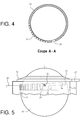
- the figure 4 is a sectional view of the rotating ring 20. It comprises the notches 25 and the slot 26.
- the shape of the notches allows to adjust the force required to go from one notch to another. The deeper the notches, the more the jump of the screen requires a big force.
- the interval between two notches determines the sensitivity of the braking force adjusting device.
- the number of notches determines the number of possible positions of the ring and its rotational stroke.
- the figure 5 represents the rotating ring 20 mounted in its support 30.
- the ring 20 is mounted in the recess 31 of the fixed support and rests on its shoulder 22.
- the fixed pin 32 is housed in the oblong 24 of the ring and the finger of indexing 33 in one of the notches 25 of the ring.
- the rotation of the ring is provided by the operating lever 27. It causes the displacement of the pin 32 in the oblong 24, the change indexed notch and a translational movement of the ring parallel to the axis of revolution of the cylinder.
- the flexible seal 21 which rests on the control ball 10 then exerts a greater or lesser pressure depending on the elevation of the ring 20.
- the hollow cylinder of the ring may comprise at least a second oblong identical to the first oblong and a second plurality of notches identical to the first plurality of notches. This second set oblong-notches being arranged symmetrically with respect to the first set oblong-notches. This avoids the effects of buttressing of the ring in its support.
Landscapes
- Engineering & Computer Science (AREA)
- General Engineering & Computer Science (AREA)
- Theoretical Computer Science (AREA)
- Human Computer Interaction (AREA)
- Physics & Mathematics (AREA)
- General Physics & Mathematics (AREA)
- Mechanical Engineering (AREA)
- Position Input By Displaying (AREA)
- User Interface Of Digital Computer (AREA)
Description
- Le domaine général de l'invention est celui des boules de commande, connues aussi sous le nom de « trackballs ». Ces dispositifs sont utilisés pour commander un curseur graphique sur un ou des écrans de visualisation. On peut ainsi sélectionner et/ou modifier une unité de visualisation, une fenêtre d'affichage ou un paramètre affiché. Le domaine plus particulier de l'invention est celui des trackballs utilisés dans les cockpits d'aéronef.
- Les cockpits d'aéronefs modernes comportent un système de visualisation comprenant plusieurs écrans d'affichage. La commande et la modification des informations affichées se fait au moyen de différents interfaces homme-machine. La trackball constitue une de ses interfaces. Elle est constituée principalement d'une boule de commande dont la partie supérieure est accessible à l'utilisateur. La partie inférieure repose sur des capteurs de mouvement qui peuvent être de différents types et qui détectent les rotations de la boule dans deux directions perpendiculaires. Les informations des capteurs permettent de déplacer un curseur graphique sur un écran de visualisation.
- En application aéronautique, la boule de commande est soumise, pendant certaines phases de vol, à des vibrations ou à des accélérations qui peuvent être élevées. Aussi, il n'est pas possible de la laisser tourner librement. Elle doit être freinée pour empêcher tout mouvement parasite pendant ces phases critiques. Ce réglage est délicat dans la mesure où la boule doit être suffisamment freinée pour ne pas être sensible aux vibrations mais la rotation doit rester suffisamment souple pour qu'un utilisateur puisse tourner la boule sans effort important.
- Actuellement, le réglage du frein est assuré par un montage représenté en
figure 1 . Une bague 2 comportant un joint souple 3 est fixée sur le corps 4 du dispositif qui comporte la boule de commande 1. Cette bague entoure la partie supérieure de la boule de commande. La force de freinage du joint souple est assurée par des cales 5 disposées entre la partie inférieure de la bague 2 et le corps 4. Elle est symbolisée par les deux flèches blanches inclinées de lafigure 1 . Cette solution présente deux inconvénients. Elle est complexe à mettre en oeuvre. Par ailleurs, en exploitation, les forces de freinage augmentent progressivement. Ce durcissement est dû à un encrassement des différents éléments mécaniques tels que les axes, les bagues, les roulements, lié à une utilisation intensive sur avion. A terme, la boule de commande doit être déposée, démontée et nettoyée. Des solutions voisines ont été proposées. Le documentEP 2 927 785 propose ainsi un dispositif à boule de commande comportant une bague de frottement. Le documentUS 2012/0038495 décrit un dispositif à boule de commande comportant un dispositif de freinage asservi. - Le dispositif selon l'invention ne présente pas ces inconvénients. En effet, il permet d'effectuer facilement le réglage sans avoir à démonter ou à changer ou à nettoyer des pièces mécaniques. Plus précisément, l'invention a pour objet un dispositif à boule de commande ou « trackball » comportant une boule de commande et un dispositif de réglage de l'effort de freinage de la boule de commande, caractérisé en ce que ledit dispositif de réglage comporte :
- une bague tournante en forme de cylindre creux circulaire droit d'un diamètre intérieur supérieur à celui de la boule, ladite bague étant surmontée d'un joint annulaire de freinage souple de diamètre intérieur inférieur à celui de la boule et reposant sur celle-ci, la périphérie extérieure du cylindre comportant :
- un premier oblong incliné d'un angle de quelques degrés par rapport à la base du cylindre ;
- une première pluralité de crans identiques perpendiculaires à ladite base du cylindre, le diamètre intérieur du cylindre creux étant d'un diamètre supérieur à celui de la boule de commande et le diamètre intérieur du joint annulaire étant inférieur à celui de boule de commande ;
- Un support fixe de ladite boule de commande comportant :
- Un évidement circulaire de diamètre égal à celui de la périphérie extérieure du cylindre, la boule étant montée dans cet évidement;
- un pion fixe et un doigt d'indexage agencés de façon que, la bague étant montée dans l'évidement du support fixe, le pion fixe se loge dans l'oblong de la bague et le doigt d'indexage dans un des crans de la bague, la rotation de la bague entraînant le déplacement du pion dans l'oblong, le changement de cran indexé et un mouvement de translation de la bague parallèlement à l'axe de révolution du cylindre.
- Avantageusement, le cylindre creux de la bague comporte au moins un second oblong identique au premier oblong et une seconde pluralité de crans identique à la première pluralité de crans.
- Avantageusement, la périphérie extérieure du cylindre comporte un levier de manoeuvre de la bague.
- Avantageusement, le support fixe comporte des marquages permettant de repérer la position du levier de manoeuvre.
- Avantageusement, la périphérie extérieure du cylindre comporte à l'entrée de l'oblong une fente permettant d'entrer la bague tournante dans le support.
- Avantageusement, le support comporte des moyens d'obturation de la fente de façon à éviter tout retrait de la bague tournante montée dans son support.
- L'invention sera mieux comprise et d'autres avantages apparaîtront à la lecture de la description qui va suivre donnée à titre non limitatif et grâce aux figures annexées parmi lesquelles :
- La
figure 1 représente le montage d'une boule de commande selon l'art antérieur ; - La
figure 2 représente le principe technique du dispositif de réglage de l'effort de freinage d'une boule de commande selon l'invention ; - La
figure 3 représente une vue de face éclatée d'un dispositif de réglage de l'effort de freinage d'une boule de commande selon l'invention ; - La
figure 4 représente une vue en coupe de la bague tournante ; - La
figure 5 représente une vue de face du dispositif de réglage précédent, une fois assemblé. - La
figure 2 représente le principe technique du dispositif de réglage de l'effort de freinage d'une boule de commande selon l'invention. Pour obtenir l'effort souhaité sur la boule de commande, la bague 2 comportant le joint souple 3 n'est plus fixée sur le support mais est mécaniquement réglable en hauteur comme indiqué par les flèches doubles blanches de lafigure 2 . Ainsi, lorsque l'utilisateur élève la bague dans son support, la pression exercée par le joint sur la boule diminue et cette pression augmente dans le cas contraire. Cette disposition présente trois avantages principaux. Le premier est une réduction considérable du temps de réglage et d'assemblage de la trackball. Le second avantage est la possibilité d'ajuster l'effort de réglage sans démontage par l'utilisateur final. Enfin, on assure une plus grande durée de vie de la trackball dans la mesure où, lorsque la boule s'encrasse, on peut réduire l'effort nécessaire à la rotation par un simple déplacement de la bague. - Il existe différents moyens mécaniques permettant d'assurer la translation de la bague. Cependant, cette translation a un certain nombre de caractéristiques. Son amplitude est faible, de l'ordre du millimètre. On doit donc assurer le réglage avec une grande précision. La position de la bague doit également se conserver lorsque l'utilisateur fait tourner la boule de commande. Enfin, le réglage doit se faire simplement par l'utilisateur.
- Le dispositif de réglage de l'effort de freinage d'une boule de commande selon l'invention remplit ces différents critères. La bague comporte des moyens mécaniques permettant de transformer sa rotation en un mouvement de translation de faible amplitude, la transformation étant assurée par un pion fixe coulissant dans un oblong mobile.
- Ce dispositif est représenté sur la vue de face éclatée de la
figure 3 . Celle-ci comporte une bague tournante 20, une boule de commande 10 et un support 30 représenté en coupe partielle. - La bague tournante 20 est en forme de cylindre creux circulaire droit. La bague 20 est surmontée d'un joint 21 annulaire de freinage souple. Elle comporte un épaulement circulaire 22. Cet épaulement possède un levier de manoeuvre 27. La périphérie extérieure 23 du cylindre comporte :
- un premier oblong 24 incliné d'un angle de quelques degrés par rapport à la base du cylindre. Plus cet angle est faible, plus la rotation de la bague doit être importante pour provoquer son déplacement en rotation;
- une première pluralité de crans 25 identiques perpendiculaires à ladite base du cylindre.
- Le diamètre intérieur du cylindre creux est d'un diamètre supérieur à celui de la boule de commande et le diamètre intérieur du joint annulaire est inférieur à celui de boule de commande. La périphérie extérieure du cylindre comporte à l'entrée de l'oblong 24 une fente ou échappatoire 26 permettant d'entrer la bague tournante dans le support 30. Cette fente peut comporter des moyens d'obturation afin d'éviter tout retrait involontaire de la bague dans son support.
- Le support fixe 30 comporte :
- Un évidement circulaire 31 de diamètre égal à celui de la périphérie extérieure du cylindre ;
- un pion fixe 32 et un doigt d'indexage 33 ;
- des marquages permettant de repérer la position du levier de manoeuvre 27.
- La
figure 4 représente une vue en coupe de la bague tournante 20. Elle comporte les crans 25 et la fente 26. La forme des crans permet de régler la force nécessaire pour passer d'un cran à l'autre. Plus les crans sont profonds, plus le saut de cran nécessite une force importante. L'intervalle entre deux crans détermine la sensibilité du dispositif de réglage de l'effort de freinage. Le nombre de crans détermine le nombre de positions possibles de la bague et sa course en rotation. - La
figure 5 représente la bague tournante 20 montée dans son support 30. La bague 20 est montée dans l'évidement 31 du support fixe et repose sur son épaulement 22. Le pion fixe 32 se loge dans l'oblong 24 de la bague et le doigt d'indexage 33 dans un des crans 25 de la bague. - La rotation de la bague est assurée par le levier de manoeuvre 27. Il entraîne le déplacement du pion 32 dans l'oblong 24, le changement de cran indexé et un mouvement de translation de la bague parallèlement à l'axe de révolution du cylindre. Le joint souple 21 qui repose sur la boule de commande 10 exerce alors une pression plus ou moins forte selon l'élévation de la bague 20.
- Le cylindre creux de la bague peut comporter au moins un second oblong identique au premier oblong et une seconde pluralité de crans identique à la première pluralité de crans. Ce second ensemble oblong-crans étant disposé symétriquement par rapport au premier ensemble oblong-crans. On évite ainsi les effets d'arc-boutement de la bague dans son support.
- La réalisation des différentes pièces mécaniques du dispositif ne pose pas de problèmes particuliers dans la mesure où elles ne nécessitent pas de haute précision de réalisation.
Claims (6)
- Dispositif à boule de commande ou « trackball » comportant une boule de commande et un dispositif de réglage de l'effort de freinage de la boule de commande, caractérisé en ce que ledit dispositif de réglage comporte :- une bague tournante (20) en forme de cylindre creux circulaire droit d'un diamètre intérieur supérieur à celui de la boule, ladite bague étant surmontée d'un joint (21) annulaire de freinage souple de diamètre intérieur inférieur à celui de la boule et reposant sur celle-ci, la périphérie extérieure du cylindre comportant :- un premier oblong (24) incliné d'un angle de quelques degrés par rapport à la base du cylindre ;- une première pluralité de crans (25) identiques perpendiculaires à ladite base du cylindre, le diamètre intérieur du cylindre creux étant d'un diamètre supérieur à celui de la boule de commande et le diamètre intérieur du joint annulaire étant inférieur à celui de boule de commande ;- Un support fixe (30) de ladite boule de commande comportant :- Un évidement circulaire (31) de diamètre égal à celui de la périphérie extérieure du cylindre, la boule étant montée dans cet évidement;- un pion fixe (32) et un doigt d'indexage (33) agencés de façon que, la bague étant montée dans l'évidement du support fixe, le pion fixe se loge dans l'oblong de la bague et le doigt d'indexage dans un des crans de la bague, la rotation de la bague entraînant le déplacement du pion dans l'oblong, le changement de cran indexé et un mouvement de translation de la bague parallèlement à l'axe de révolution du cylindre.
- Dispositif à boule de commande selon la revendication 1, caractérisé en ce que le cylindre creux de la bague comporte au moins un second oblong identique au premier oblong et une seconde pluralité de crans identique à la première pluralité de crans.
- Dispositif à boule de commande selon l'une des revendications précédentes, caractérisé en ce que la périphérie extérieure du cylindre comporte un levier de manoeuvre (27) de la bague (20).
- Dispositif à boule de commande selon la revendication 3, caractérisé en ce que le support fixe comporte des marquages permettant de repérer la position du levier de manoeuvre.
- Dispositif à boule de commande selon l'une des revendications précédentes, caractérisé en ce que la périphérie extérieure du cylindre comporte à l'entrée de l'oblong une fente (26) permettant d'entrer la bague tournante dans le support.
- Dispositif à boule de commande selon la revendication 5, caractérisé en ce que le support comporte des moyens d'obturation de la fente de façon à éviter tout retrait de la bague tournante montée dans son support.
Applications Claiming Priority (1)
| Application Number | Priority Date | Filing Date | Title |
|---|---|---|---|
| FR1600983A FR3052888B1 (fr) | 2016-06-21 | 2016-06-21 | Dispositif de reglage de l'effort de freinage d'une boule de commande ou "trackbal" et boule de commande associee |
Publications (2)
| Publication Number | Publication Date |
|---|---|
| EP3260957A1 EP3260957A1 (fr) | 2017-12-27 |
| EP3260957B1 true EP3260957B1 (fr) | 2018-12-26 |
Family
ID=56801613
Family Applications (1)
| Application Number | Title | Priority Date | Filing Date |
|---|---|---|---|
| EP17176463.2A Active EP3260957B1 (fr) | 2016-06-21 | 2017-06-16 | Dispositif de reglage de l'effort de freinage d'une boule de commande ou " trackball " et boule de commande associee |
Country Status (3)
| Country | Link |
|---|---|
| US (1) | US10289216B2 (fr) |
| EP (1) | EP3260957B1 (fr) |
| FR (1) | FR3052888B1 (fr) |
Families Citing this family (7)
| Publication number | Priority date | Publication date | Assignee | Title |
|---|---|---|---|---|
| US10496216B2 (en) | 2016-11-09 | 2019-12-03 | Dell Products L.P. | Information handling system capacitive touch totem with optical communication support |
| US10817077B2 (en) | 2018-06-28 | 2020-10-27 | Dell Products, L.P. | Information handling system touch device context aware input tracking |
| US10852853B2 (en) | 2018-06-28 | 2020-12-01 | Dell Products L.P. | Information handling system touch device with visually interactive region |
| US10761618B2 (en) | 2018-06-28 | 2020-09-01 | Dell Products L.P. | Information handling system touch device with automatically orienting visual display |
| US10795502B2 (en) | 2018-06-28 | 2020-10-06 | Dell Products L.P. | Information handling system touch device with adaptive haptic response |
| US10635199B2 (en) * | 2018-06-28 | 2020-04-28 | Dell Products L.P. | Information handling system dynamic friction touch device for touchscreen interactions |
| US10664101B2 (en) | 2018-06-28 | 2020-05-26 | Dell Products L.P. | Information handling system touch device false touch detection and mitigation |
Family Cites Families (13)
| Publication number | Priority date | Publication date | Assignee | Title |
|---|---|---|---|---|
| DE69214866T2 (de) * | 1991-04-05 | 1997-06-26 | Logitech Inc | Auf einer Tastatur montierte Rollkugel |
| US5237311A (en) * | 1991-08-01 | 1993-08-17 | Picker International, Inc. | Hingedly supported integrated trackball and selection device |
| US5280276A (en) * | 1992-07-10 | 1994-01-18 | Quickshot (Bvi) Ltd. | Combination mouse/trackball input device |
| CN1322404C (zh) * | 2000-02-07 | 2007-06-20 | 松下电器产业株式会社 | 跟踪球装置和使用该跟踪球装置的电子装置 |
| US7522155B2 (en) * | 2003-01-16 | 2009-04-21 | Panasonic Corporation | Trackball device and vehicle incorporating the same |
| FR2887657B1 (fr) * | 2005-06-27 | 2007-09-07 | Itt Mfg Enterprises Inc | Dispositif a boule de commande des deplacements d'un curseur sur un ecran |
| EP1752101A3 (fr) * | 2005-08-08 | 2007-05-30 | Medison Co., Ltd. | Panneau de commande pour un appareil de diagnostic a ultrasons |
| DE112007003571T5 (de) * | 2007-07-02 | 2010-05-12 | Razer (Asia-Pacific) Pte. Ltd. | Spielsteuerungsvorrichtung mit klickbarer Rollkugel |
| US20110109555A1 (en) * | 2009-11-06 | 2011-05-12 | Honda Motor Co., Ltd. | Interface system including trackball |
| JP2012043005A (ja) * | 2010-08-12 | 2012-03-01 | Alps Electric Co Ltd | 操作感触付与型トラックボール装置 |
| US8994661B2 (en) * | 2012-06-29 | 2015-03-31 | Google Technology Holdings LLC | User interface device having capacitive trackball assembly |
| FR3019663B1 (fr) * | 2014-04-04 | 2016-05-06 | Thales Sa | Frein d'une boule de designation |
| FR3025903B1 (fr) * | 2014-09-17 | 2017-11-03 | Thales Sa | Dispositif d'entrée de données et ses moyens de freinage |
-
2016
- 2016-06-21 FR FR1600983A patent/FR3052888B1/fr not_active Expired - Fee Related
-
2017
- 2017-06-16 US US15/625,881 patent/US10289216B2/en active Active
- 2017-06-16 EP EP17176463.2A patent/EP3260957B1/fr active Active
Non-Patent Citations (1)
| Title |
|---|
| None * |
Also Published As
| Publication number | Publication date |
|---|---|
| FR3052888A1 (fr) | 2017-12-22 |
| FR3052888B1 (fr) | 2018-07-13 |
| US20170364168A1 (en) | 2017-12-21 |
| US10289216B2 (en) | 2019-05-14 |
| EP3260957A1 (fr) | 2017-12-27 |
Similar Documents
| Publication | Publication Date | Title |
|---|---|---|
| EP3260957A1 (fr) | Dispositif de reglage de l'effort de freinage d'une boule de commande ou " trackball " et boule de commande associee | |
| EP3069045B1 (fr) | Dispositif simplifie d'amortissement de torsion a pendule | |
| WO2011098712A1 (fr) | Ensemble avec dispositif de commande par cremailleres de la position angulaire d'aubes pivotantes de turbomachine | |
| EP0457781B1 (fr) | Dispositif de verrouillage lineaire ou circulaire, du type dit a cliquet, autobloquant et a deblocage automatique | |
| CA3129470A1 (fr) | Dispositif de guidage d'une aiguille medicale | |
| EP2256039A1 (fr) | Pivot traversant à éléments flexibles et engin spatial comportant un tel pivot | |
| EP2386848A1 (fr) | Installation de contrôle de la qualité d'une surface d'un objet | |
| CA2813569A1 (fr) | Boitier de liaison entre un arbre d'entrainement de soufflante de moteur et un palier de roulement | |
| FR3067415B1 (fr) | Systeme de commande du calage des pales d'une helice d'une turbomachine | |
| FR2966646A1 (fr) | Positionneur d'antenne parabolique | |
| WO2019238949A1 (fr) | Dispositif de veille proximale | |
| EP2290430B1 (fr) | Dispositif de mesure de bougé de ligne de visée d'instrument optique | |
| FR2999674A1 (fr) | Systeme comprenant une vis a rouleaux | |
| EP1964778A1 (fr) | Pivot traversant à lames | |
| EP4118479B1 (fr) | Procédé d'acquisition d'image d'un astre et appareil pour la mise en oeuvre du procédé | |
| EP2927784B1 (fr) | Amélioration de l'ergonomie d'un dispositif d'entrée de données | |
| EP1672309A1 (fr) | Tête de mesure orientable motorisée | |
| CH620033A5 (fr) | ||
| EP3179291B1 (fr) | Procede d'affichage d'un " indicateur de directeur d'attitude " dans un systeme de visualisation de tete pour aeronef | |
| EP2024152B1 (fr) | Unite de transfert de corps tubulaires | |
| FR2561323A1 (fr) | Mecanisme de blocage par friction a masselottes et excentriques | |
| EP3538788B1 (fr) | Dispositif de transmission mecanique | |
| EP2998835A1 (fr) | Dispositif d'entree de donnees et ses moyens de freinage | |
| EP3094981B1 (fr) | Dispositif mécanique de détection d'accélération angulaire | |
| FR3028099A1 (fr) | Dispositif d'orientation d'un element mobile du type plateau d'antenne |
Legal Events
| Date | Code | Title | Description |
|---|---|---|---|
| PUAI | Public reference made under article 153(3) epc to a published international application that has entered the european phase |
Free format text: ORIGINAL CODE: 0009012 |
|
| STAA | Information on the status of an ep patent application or granted ep patent |
Free format text: STATUS: THE APPLICATION HAS BEEN PUBLISHED |
|
| AK | Designated contracting states |
Kind code of ref document: A1 Designated state(s): AL AT BE BG CH CY CZ DE DK EE ES FI FR GB GR HR HU IE IS IT LI LT LU LV MC MK MT NL NO PL PT RO RS SE SI SK SM TR |
|
| AX | Request for extension of the european patent |
Extension state: BA ME |
|
| STAA | Information on the status of an ep patent application or granted ep patent |
Free format text: STATUS: REQUEST FOR EXAMINATION WAS MADE |
|
| 17P | Request for examination filed |
Effective date: 20180615 |
|
| RBV | Designated contracting states (corrected) |
Designated state(s): AL AT BE BG CH CY CZ DE DK EE ES FI FR GB GR HR HU IE IS IT LI LT LU LV MC MK MT NL NO PL PT RO RS SE SI SK SM TR |
|
| RIC1 | Information provided on ipc code assigned before grant |
Ipc: G06F 3/0354 20130101AFI20180703BHEP |
|
| GRAP | Despatch of communication of intention to grant a patent |
Free format text: ORIGINAL CODE: EPIDOSNIGR1 |
|
| STAA | Information on the status of an ep patent application or granted ep patent |
Free format text: STATUS: GRANT OF PATENT IS INTENDED |
|
| INTG | Intention to grant announced |
Effective date: 20180814 |
|
| GRAS | Grant fee paid |
Free format text: ORIGINAL CODE: EPIDOSNIGR3 |
|
| GRAA | (expected) grant |
Free format text: ORIGINAL CODE: 0009210 |
|
| STAA | Information on the status of an ep patent application or granted ep patent |
Free format text: STATUS: THE PATENT HAS BEEN GRANTED |
|
| AK | Designated contracting states |
Kind code of ref document: B1 Designated state(s): AL AT BE BG CH CY CZ DE DK EE ES FI FR GB GR HR HU IE IS IT LI LT LU LV MC MK MT NL NO PL PT RO RS SE SI SK SM TR |
|
| REG | Reference to a national code |
Ref country code: GB Ref legal event code: FG4D Free format text: NOT ENGLISH |
|
| REG | Reference to a national code |
Ref country code: CH Ref legal event code: EP |
|
| REG | Reference to a national code |
Ref country code: AT Ref legal event code: REF Ref document number: 1082308 Country of ref document: AT Kind code of ref document: T Effective date: 20190115 |
|
| REG | Reference to a national code |
Ref country code: IE Ref legal event code: FG4D Free format text: LANGUAGE OF EP DOCUMENT: FRENCH |
|
| REG | Reference to a national code |
Ref country code: DE Ref legal event code: R096 Ref document number: 602017001567 Country of ref document: DE |
|
| PG25 | Lapsed in a contracting state [announced via postgrant information from national office to epo] |
Ref country code: FI Free format text: LAPSE BECAUSE OF FAILURE TO SUBMIT A TRANSLATION OF THE DESCRIPTION OR TO PAY THE FEE WITHIN THE PRESCRIBED TIME-LIMIT Effective date: 20181226 Ref country code: NO Free format text: LAPSE BECAUSE OF FAILURE TO SUBMIT A TRANSLATION OF THE DESCRIPTION OR TO PAY THE FEE WITHIN THE PRESCRIBED TIME-LIMIT Effective date: 20190326 Ref country code: LV Free format text: LAPSE BECAUSE OF FAILURE TO SUBMIT A TRANSLATION OF THE DESCRIPTION OR TO PAY THE FEE WITHIN THE PRESCRIBED TIME-LIMIT Effective date: 20181226 Ref country code: LT Free format text: LAPSE BECAUSE OF FAILURE TO SUBMIT A TRANSLATION OF THE DESCRIPTION OR TO PAY THE FEE WITHIN THE PRESCRIBED TIME-LIMIT Effective date: 20181226 Ref country code: BG Free format text: LAPSE BECAUSE OF FAILURE TO SUBMIT A TRANSLATION OF THE DESCRIPTION OR TO PAY THE FEE WITHIN THE PRESCRIBED TIME-LIMIT Effective date: 20190326 Ref country code: HR Free format text: LAPSE BECAUSE OF FAILURE TO SUBMIT A TRANSLATION OF THE DESCRIPTION OR TO PAY THE FEE WITHIN THE PRESCRIBED TIME-LIMIT Effective date: 20181226 |
|
| REG | Reference to a national code |
Ref country code: NL Ref legal event code: MP Effective date: 20181226 |
|
| REG | Reference to a national code |
Ref country code: LT Ref legal event code: MG4D |
|
| PG25 | Lapsed in a contracting state [announced via postgrant information from national office to epo] |
Ref country code: AL Free format text: LAPSE BECAUSE OF FAILURE TO SUBMIT A TRANSLATION OF THE DESCRIPTION OR TO PAY THE FEE WITHIN THE PRESCRIBED TIME-LIMIT Effective date: 20181226 Ref country code: SE Free format text: LAPSE BECAUSE OF FAILURE TO SUBMIT A TRANSLATION OF THE DESCRIPTION OR TO PAY THE FEE WITHIN THE PRESCRIBED TIME-LIMIT Effective date: 20181226 Ref country code: GR Free format text: LAPSE BECAUSE OF FAILURE TO SUBMIT A TRANSLATION OF THE DESCRIPTION OR TO PAY THE FEE WITHIN THE PRESCRIBED TIME-LIMIT Effective date: 20190327 Ref country code: RS Free format text: LAPSE BECAUSE OF FAILURE TO SUBMIT A TRANSLATION OF THE DESCRIPTION OR TO PAY THE FEE WITHIN THE PRESCRIBED TIME-LIMIT Effective date: 20181226 |
|
| REG | Reference to a national code |
Ref country code: AT Ref legal event code: MK05 Ref document number: 1082308 Country of ref document: AT Kind code of ref document: T Effective date: 20181226 |
|
| PG25 | Lapsed in a contracting state [announced via postgrant information from national office to epo] |
Ref country code: NL Free format text: LAPSE BECAUSE OF FAILURE TO SUBMIT A TRANSLATION OF THE DESCRIPTION OR TO PAY THE FEE WITHIN THE PRESCRIBED TIME-LIMIT Effective date: 20181226 |
|
| PG25 | Lapsed in a contracting state [announced via postgrant information from national office to epo] |
Ref country code: CZ Free format text: LAPSE BECAUSE OF FAILURE TO SUBMIT A TRANSLATION OF THE DESCRIPTION OR TO PAY THE FEE WITHIN THE PRESCRIBED TIME-LIMIT Effective date: 20181226 Ref country code: PT Free format text: LAPSE BECAUSE OF FAILURE TO SUBMIT A TRANSLATION OF THE DESCRIPTION OR TO PAY THE FEE WITHIN THE PRESCRIBED TIME-LIMIT Effective date: 20190426 Ref country code: ES Free format text: LAPSE BECAUSE OF FAILURE TO SUBMIT A TRANSLATION OF THE DESCRIPTION OR TO PAY THE FEE WITHIN THE PRESCRIBED TIME-LIMIT Effective date: 20181226 Ref country code: PL Free format text: LAPSE BECAUSE OF FAILURE TO SUBMIT A TRANSLATION OF THE DESCRIPTION OR TO PAY THE FEE WITHIN THE PRESCRIBED TIME-LIMIT Effective date: 20181226 |
|
| PG25 | Lapsed in a contracting state [announced via postgrant information from national office to epo] |
Ref country code: EE Free format text: LAPSE BECAUSE OF FAILURE TO SUBMIT A TRANSLATION OF THE DESCRIPTION OR TO PAY THE FEE WITHIN THE PRESCRIBED TIME-LIMIT Effective date: 20181226 Ref country code: RO Free format text: LAPSE BECAUSE OF FAILURE TO SUBMIT A TRANSLATION OF THE DESCRIPTION OR TO PAY THE FEE WITHIN THE PRESCRIBED TIME-LIMIT Effective date: 20181226 Ref country code: IS Free format text: LAPSE BECAUSE OF FAILURE TO SUBMIT A TRANSLATION OF THE DESCRIPTION OR TO PAY THE FEE WITHIN THE PRESCRIBED TIME-LIMIT Effective date: 20190426 Ref country code: SM Free format text: LAPSE BECAUSE OF FAILURE TO SUBMIT A TRANSLATION OF THE DESCRIPTION OR TO PAY THE FEE WITHIN THE PRESCRIBED TIME-LIMIT Effective date: 20181226 Ref country code: SK Free format text: LAPSE BECAUSE OF FAILURE TO SUBMIT A TRANSLATION OF THE DESCRIPTION OR TO PAY THE FEE WITHIN THE PRESCRIBED TIME-LIMIT Effective date: 20181226 |
|
| REG | Reference to a national code |
Ref country code: DE Ref legal event code: R097 Ref document number: 602017001567 Country of ref document: DE |
|
| PG25 | Lapsed in a contracting state [announced via postgrant information from national office to epo] |
Ref country code: AT Free format text: LAPSE BECAUSE OF FAILURE TO SUBMIT A TRANSLATION OF THE DESCRIPTION OR TO PAY THE FEE WITHIN THE PRESCRIBED TIME-LIMIT Effective date: 20181226 Ref country code: DK Free format text: LAPSE BECAUSE OF FAILURE TO SUBMIT A TRANSLATION OF THE DESCRIPTION OR TO PAY THE FEE WITHIN THE PRESCRIBED TIME-LIMIT Effective date: 20181226 |
|
| PLBE | No opposition filed within time limit |
Free format text: ORIGINAL CODE: 0009261 |
|
| STAA | Information on the status of an ep patent application or granted ep patent |
Free format text: STATUS: NO OPPOSITION FILED WITHIN TIME LIMIT |
|
| 26N | No opposition filed |
Effective date: 20190927 |
|
| PG25 | Lapsed in a contracting state [announced via postgrant information from national office to epo] |
Ref country code: MC Free format text: LAPSE BECAUSE OF FAILURE TO SUBMIT A TRANSLATION OF THE DESCRIPTION OR TO PAY THE FEE WITHIN THE PRESCRIBED TIME-LIMIT Effective date: 20181226 |
|
| PG25 | Lapsed in a contracting state [announced via postgrant information from national office to epo] |
Ref country code: SI Free format text: LAPSE BECAUSE OF FAILURE TO SUBMIT A TRANSLATION OF THE DESCRIPTION OR TO PAY THE FEE WITHIN THE PRESCRIBED TIME-LIMIT Effective date: 20181226 |
|
| REG | Reference to a national code |
Ref country code: BE Ref legal event code: MM Effective date: 20190630 |
|
| PG25 | Lapsed in a contracting state [announced via postgrant information from national office to epo] |
Ref country code: TR Free format text: LAPSE BECAUSE OF FAILURE TO SUBMIT A TRANSLATION OF THE DESCRIPTION OR TO PAY THE FEE WITHIN THE PRESCRIBED TIME-LIMIT Effective date: 20181226 |
|
| PG25 | Lapsed in a contracting state [announced via postgrant information from national office to epo] |
Ref country code: IE Free format text: LAPSE BECAUSE OF NON-PAYMENT OF DUE FEES Effective date: 20190616 |
|
| PG25 | Lapsed in a contracting state [announced via postgrant information from national office to epo] |
Ref country code: LU Free format text: LAPSE BECAUSE OF NON-PAYMENT OF DUE FEES Effective date: 20190616 Ref country code: BE Free format text: LAPSE BECAUSE OF NON-PAYMENT OF DUE FEES Effective date: 20190630 |
|
| REG | Reference to a national code |
Ref country code: CH Ref legal event code: PL |
|
| PG25 | Lapsed in a contracting state [announced via postgrant information from national office to epo] |
Ref country code: CH Free format text: LAPSE BECAUSE OF NON-PAYMENT OF DUE FEES Effective date: 20200630 Ref country code: LI Free format text: LAPSE BECAUSE OF NON-PAYMENT OF DUE FEES Effective date: 20200630 |
|
| PG25 | Lapsed in a contracting state [announced via postgrant information from national office to epo] |
Ref country code: CY Free format text: LAPSE BECAUSE OF FAILURE TO SUBMIT A TRANSLATION OF THE DESCRIPTION OR TO PAY THE FEE WITHIN THE PRESCRIBED TIME-LIMIT Effective date: 20181226 |
|
| PG25 | Lapsed in a contracting state [announced via postgrant information from national office to epo] |
Ref country code: MT Free format text: LAPSE BECAUSE OF FAILURE TO SUBMIT A TRANSLATION OF THE DESCRIPTION OR TO PAY THE FEE WITHIN THE PRESCRIBED TIME-LIMIT Effective date: 20181226 Ref country code: HU Free format text: LAPSE BECAUSE OF FAILURE TO SUBMIT A TRANSLATION OF THE DESCRIPTION OR TO PAY THE FEE WITHIN THE PRESCRIBED TIME-LIMIT; INVALID AB INITIO Effective date: 20170616 |
|
| PG25 | Lapsed in a contracting state [announced via postgrant information from national office to epo] |
Ref country code: MK Free format text: LAPSE BECAUSE OF FAILURE TO SUBMIT A TRANSLATION OF THE DESCRIPTION OR TO PAY THE FEE WITHIN THE PRESCRIBED TIME-LIMIT Effective date: 20181226 |
|
| P01 | Opt-out of the competence of the unified patent court (upc) registered |
Effective date: 20230427 |
|
| PGFP | Annual fee paid to national office [announced via postgrant information from national office to epo] |
Ref country code: IT Payment date: 20230526 Year of fee payment: 7 |
|
| PGFP | Annual fee paid to national office [announced via postgrant information from national office to epo] |
Ref country code: GB Payment date: 20230518 Year of fee payment: 7 |
|
| GBPC | Gb: european patent ceased through non-payment of renewal fee |
Effective date: 20240616 |
|
| PG25 | Lapsed in a contracting state [announced via postgrant information from national office to epo] |
Ref country code: IT Free format text: LAPSE BECAUSE OF NON-PAYMENT OF DUE FEES Effective date: 20240616 Ref country code: GB Free format text: LAPSE BECAUSE OF NON-PAYMENT OF DUE FEES Effective date: 20240616 |
|
| PGFP | Annual fee paid to national office [announced via postgrant information from national office to epo] |
Ref country code: DE Payment date: 20250514 Year of fee payment: 9 |
|
| PGFP | Annual fee paid to national office [announced via postgrant information from national office to epo] |
Ref country code: FR Payment date: 20250523 Year of fee payment: 9 |