EP3260942A1 - Plant operation assistance system and plant operation assistance method - Google Patents
Plant operation assistance system and plant operation assistance method Download PDFInfo
- Publication number
- EP3260942A1 EP3260942A1 EP16755087.0A EP16755087A EP3260942A1 EP 3260942 A1 EP3260942 A1 EP 3260942A1 EP 16755087 A EP16755087 A EP 16755087A EP 3260942 A1 EP3260942 A1 EP 3260942A1
- Authority
- EP
- European Patent Office
- Prior art keywords
- plant
- monitoring data
- probability distribution
- state quantity
- operation assistance
- Prior art date
- Legal status (The legal status is an assumption and is not a legal conclusion. Google has not performed a legal analysis and makes no representation as to the accuracy of the status listed.)
- Granted
Links
Images




Classifications
-
- G—PHYSICS
- G21—NUCLEAR PHYSICS; NUCLEAR ENGINEERING
- G21D—NUCLEAR POWER PLANT
- G21D3/00—Control of nuclear power plant
- G21D3/001—Computer implemented control
-
- G—PHYSICS
- G05—CONTROLLING; REGULATING
- G05B—CONTROL OR REGULATING SYSTEMS IN GENERAL; FUNCTIONAL ELEMENTS OF SUCH SYSTEMS; MONITORING OR TESTING ARRANGEMENTS FOR SUCH SYSTEMS OR ELEMENTS
- G05B17/00—Systems involving the use of models or simulators of said systems
- G05B17/02—Systems involving the use of models or simulators of said systems electric
-
- G—PHYSICS
- G05—CONTROLLING; REGULATING
- G05B—CONTROL OR REGULATING SYSTEMS IN GENERAL; FUNCTIONAL ELEMENTS OF SUCH SYSTEMS; MONITORING OR TESTING ARRANGEMENTS FOR SUCH SYSTEMS OR ELEMENTS
- G05B23/00—Testing or monitoring of control systems or parts thereof
- G05B23/02—Electric testing or monitoring
- G05B23/0205—Electric testing or monitoring by means of a monitoring system capable of detecting and responding to faults
- G05B23/0218—Electric testing or monitoring by means of a monitoring system capable of detecting and responding to faults characterised by the fault detection method dealing with either existing or incipient faults
- G05B23/0243—Electric testing or monitoring by means of a monitoring system capable of detecting and responding to faults characterised by the fault detection method dealing with either existing or incipient faults model based detection method, e.g. first-principles knowledge model
-
- G—PHYSICS
- G21—NUCLEAR PHYSICS; NUCLEAR ENGINEERING
- G21C—NUCLEAR REACTORS
- G21C17/00—Monitoring; Testing ; Maintaining
-
- G—PHYSICS
- G21—NUCLEAR PHYSICS; NUCLEAR ENGINEERING
- G21C—NUCLEAR REACTORS
- G21C7/00—Control of nuclear reaction
- G21C7/36—Control circuits
-
- G—PHYSICS
- G21—NUCLEAR PHYSICS; NUCLEAR ENGINEERING
- G21D—NUCLEAR POWER PLANT
- G21D3/00—Control of nuclear power plant
- G21D3/04—Safety arrangements
-
- G—PHYSICS
- G06—COMPUTING OR CALCULATING; COUNTING
- G06F—ELECTRIC DIGITAL DATA PROCESSING
- G06F2111/00—Details relating to CAD techniques
- G06F2111/08—Probabilistic or stochastic CAD
-
- G—PHYSICS
- G21—NUCLEAR PHYSICS; NUCLEAR ENGINEERING
- G21D—NUCLEAR POWER PLANT
- G21D3/00—Control of nuclear power plant
- G21D3/001—Computer implemented control
- G21D3/002—Core design; core simulations; core optimisation
-
- G—PHYSICS
- G21—NUCLEAR PHYSICS; NUCLEAR ENGINEERING
- G21D—NUCLEAR POWER PLANT
- G21D3/00—Control of nuclear power plant
- G21D3/001—Computer implemented control
- G21D3/005—Thermo-hydraulic simulations
-
- G—PHYSICS
- G21—NUCLEAR PHYSICS; NUCLEAR ENGINEERING
- G21D—NUCLEAR POWER PLANT
- G21D3/00—Control of nuclear power plant
- G21D3/007—Expert systems
-
- Y—GENERAL TAGGING OF NEW TECHNOLOGICAL DEVELOPMENTS; GENERAL TAGGING OF CROSS-SECTIONAL TECHNOLOGIES SPANNING OVER SEVERAL SECTIONS OF THE IPC; TECHNICAL SUBJECTS COVERED BY FORMER USPC CROSS-REFERENCE ART COLLECTIONS [XRACs] AND DIGESTS
- Y02—TECHNOLOGIES OR APPLICATIONS FOR MITIGATION OR ADAPTATION AGAINST CLIMATE CHANGE
- Y02E—REDUCTION OF GREENHOUSE GAS [GHG] EMISSIONS, RELATED TO ENERGY GENERATION, TRANSMISSION OR DISTRIBUTION
- Y02E30/00—Energy generation of nuclear origin
-
- Y—GENERAL TAGGING OF NEW TECHNOLOGICAL DEVELOPMENTS; GENERAL TAGGING OF CROSS-SECTIONAL TECHNOLOGIES SPANNING OVER SEVERAL SECTIONS OF THE IPC; TECHNICAL SUBJECTS COVERED BY FORMER USPC CROSS-REFERENCE ART COLLECTIONS [XRACs] AND DIGESTS
- Y02—TECHNOLOGIES OR APPLICATIONS FOR MITIGATION OR ADAPTATION AGAINST CLIMATE CHANGE
- Y02E—REDUCTION OF GREENHOUSE GAS [GHG] EMISSIONS, RELATED TO ENERGY GENERATION, TRANSMISSION OR DISTRIBUTION
- Y02E30/00—Energy generation of nuclear origin
- Y02E30/30—Nuclear fission reactors
Definitions
- the present invention relates to a plant operation assistance system and a plant operation assistance method.
- Non-Patent Literature 1 an operation assistance apparatus, which uses a prediction simulator that predicts a future operation state based on monitoring data, is disclosed.
- Patent Literature 2 and Patent Literature 3 estimation of parameters by use of a probability theory called "Bayes' theorem" is disclosed. Further, a technique for estimating and visualizing unobserved state quantity by using a deterministic model is disclosed in Non-Patent Literature 1.
- Non-Patent Literature 2 a technique for constructing a diagnostic model for a spacecraft by using a stochastic model called "Dynamic Bayesian Networks, and performing abnormality diagnosis is disclosed in Non-Patent Literature 2.
- monitoring data of the plant may include much uncertainty, and prediction of a state of the plant may become difficult.
- a deterministic model as disclosed in Patent Literature 1 and Non-Patent Literature 1 is used, if the monitoring data include uncertainty, reliability of prediction results is reduced. When the plant is operated in reliance on these prediction results, appropriate operation of the plant becomes difficult.
- the present invention aims to provide a plant operation assistance system and a plant operation assistance method, which enable prediction of a state of a plant in consideration of uncertainty in monitoring data and assistance in operation of the plant.
- the present invention provides a plant operation assistance system, including a data obtaining unit configured to obtain monitoring data indicating state quantity of a plant, the state quantity being detected by a sensor, an identifying unit configured to identify, based on the state quantity, a probability distribution of the monitoring data, a model generation unit configured to generate, based on a plant parameter composed from a database including design information of the plant, a stochastic model of the plant, a data processing unit configured to assign the probability distribution to the monitoring data obtained by the data obtaining unit, and a prediction unit configured to input the monitoring data assigned with the probability distribution into the stochastic model and predict a state of the plant.
- a data obtaining unit configured to obtain monitoring data indicating state quantity of a plant, the state quantity being detected by a sensor
- an identifying unit configured to identify, based on the state quantity, a probability distribution of the monitoring data
- a model generation unit configured to generate, based on a plant parameter composed from a database including design information of the plant, a stochastic model of the plant
- the monitoring data that have been added with the probability distribution are input into the stochastic model; which part of, to what extent, and with a probability of what level, the plant is abnormal, are able to be predicted. Further, from the prediction results, the degree of uncertainty in the monitoring data and the reliability of the prediction results are able to be estimated. Accordingly, in consideration of the uncertainty in the monitoring data and the reliability of the prediction results, the plant is able to be operated.
- the identifying unit is configured to identify the probability distribution with an output command of the plant being an index. Thereby, states of the plant corresponding to various output commands are able to be predicted.
- the plant operation assistance system may include an updating unit configured to update the stochastic model with a plant parameter identified based on a deterministic model of the plant. Thereby, even if the plant parameter is changed, the state of the plant is able to be predicted.
- the present invention provides a plant operation assistance method, including steps of obtaining monitoring data indicating state quantity of a plant, the state quantity being detected by a sensor, identifying, based on the state quantity, a probability distribution of the monitoring data, generating, based on a plant parameter composed from a database including design information of the plant, a stochastic model of the plant, assigning the probability distribution to the obtained monitoring data, and inputting the monitoring data assigned with the probability distribution into the stochastic model and predicting a state of the plant.
- a state of a plant is able to be predicted appropriately, and the plant is able to be operated in consideration of uncertainty in monitoring data and reliability of prediction results.
- a plant operation assistance system and a plant operation assistance method which enable: prediction of a state of a plant in consideration of uncertainty in monitoring data; and assistance in operation of the plant, are provided.
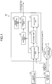
- FIG. 1 is a functional block diagram illustrating an example of a plant operation assistance system 100 according to an embodiment.
- the plant operation assistance system 100 includes a computer system.
- the plant operation assistance system 100 includes: a data obtaining unit 101 that obtains monitoring data indicating state quantity y of a plant 200, the state quantity y having been detected by a sensor 10; an identifying unit 102 that identifies, based on the state quantity y of the plant 200, a probability distribution of the monitoring data; a model generation unit 103 that generates, based on a plant parameter composed from a database including design information of the plant 200, a stochastic model of the plant 200; a data processing unit 104 that assigns the probability distribution to the monitoring data obtained by the data obtaining unit 101; a prediction unit 105 that inputs the monitoring data that have been assigned with the probability distribution, into the stochastic model, and predicts a state of the plant 200; and a storage unit 106 that stores therein data obtained by the data obtaining unit 101.
- the plant 200 is controlled by a control device 300.
- the control device 300 includes a computer system, and outputs operation quantity u for operating the plant 100, to the plant operation assistance system 100 and the plant 200.
- the state quantity y detected by the sensor 10 is output to the plant operation assistance system 100 and the control device 300.
- An output command unit 150 is connected to the control device 300.
- the output command unit 150 has an operation input unit that is operated by an operator, and generates, based on an operation, a command signal.
- the command signal is an output command signal instructing an output of the plant 200.
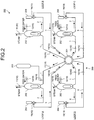
- FIG. 2 is a schematic diagram illustrating an example of the plant 200 according to the embodiment. In this embodiment, an example, in which the plant 200 is a nuclear power plant 200, will be described.
- FIG. 2 illustrates a nuclear reactor vessel 201 and a primary cooling system 250, of the nuclear power plant 200.
- the nuclear power plant 200 includes: the nuclear reactor vessel 201 having a reactor core; a steam generator 202; and a pressurizer 203 that pressurizes the primary cooling system 250.
- the nuclear reactor vessel 201 heats up primary cooling water.
- the primary cooling water that has been heated up by the nuclear reactor vessel 201 is sent to the steam generator 202 via a hot leg 1, which is a high temperature side piping.
- the steam generator 202 generates steam of secondary cooling water by performing heat exchange between the high temperature and high pressure primary cooling water that has been supplied from the nuclear reactor vessel 201 and the secondary cooling water (feed water) that has been supplied from a secondary cooling system.
- the steam generated by the steam generator 202 is supplied to a turbine generator (not illustrated) via the secondary cooling system.
- the primary cooling water that has been cooled in the steam generator 202 is sent to a cold leg 3, which is a low temperature side piping, via a crossover leg 2 and a primary cooling water pump 204, flows through the cold leg 3, and thereafter, is supplied to the nuclear reactor vessel 201.
- the primary cooling system 250 has four loops (circulation systems), which are a loop A, a loop B, a loop C, and a loop D.
- the primary cooling water that has been heated up by the nuclear reactor vessel 201 is supplied to each of the loops A, B, C, and D.
- Each of the loops A, B, C, and D has therein the steam generator 202, the primary cooling water pump 204, the hot leg 1, the crossover leg 2, and the cold leg 3.
- the primary cooling water that has flown through each of the loops A, B, C, and D is returned to the nuclear reactor vessel 201.
- examples of the state quantity y of the nuclear power plant 200 include: main steam temperature T ms indicating temperature of the steam of the secondary cooling water generated from the steam generator 202; feed water temperature T fw indicating temperature of the secondary cooling water supplied to the steam generator 202; high side temperature T ho indicating temperature of the primary cooling water flowing through the hot leg 1; low side temperature T co indicating temperature of the primary cooling water flowing through the cold leg 3; pressure P rcp indicating pressure in the primary cooling system 250; and flow rate G rcp of the primary cooling water pump 204.
- the sensor 10 includes: a main steam temperature sensor 11 that detects the main steam temperature T ms ; a feed water temperature sensor 12 that detects the feed water temperature T fw ; a high side temperature sensor 13 that detects the high side temperature T ho ; a low side temperature sensor 14 that detects the low side temperature T co ; a pressure sensor 15 that detects the pressure P rcp ; and a flow rate sensor 16 that detects the flow rate G rcp .
- the identifying unit 102 identifies, based on the observable state quantity y of the nuclear power plant 200, a probability distribution of the monitoring data.
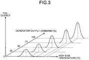
- FIG. 3 is a schematic diagram for explanation of an example of probability distributions of monitoring data. Hereinafter, description will be made by assuming that the state quantity y of the nuclear power plant 200 is the high side temperature T ho .
- the identifying unit 102 statistically derives, based on plural monitoring data (accumulated data) on the high side temperature T ho obtained in a predetermined past time period, a probability distribution for the high side temperature T ho .
- the predetermined past time period may be, for example, any of: one day; one week; one month; one year; and so on.
- an average value and variance of the high side temperature T ho in the predetermined time period are derived.
- the high side temperature T ho may fluctuate.
- the high side temperature sensor 13 monitors the high side temperature T ho , and regularly outputs monitoring data on the high side temperature T ho , to the data obtaining unit 101.
- the monitoring data on the high side temperature T ho which have been output from the high side temperature sensor 13 and obtained by the data obtaining unit 101, are accumulated in the storage unit 106.
- the identifying unit 102 derives, based on the plural monitoring data on the high side temperature T ho in the predetermined time period, the plural monitoring data having been stored in the storage unit 106, an average value and variance of the high side temperature T ho .
- the identifying unit 102 identifies, with an output command of the nuclear power plant 200 being an index, the probability distribution.
- the output command is a generator output command MWD.
- MWD generator output command
- an output range of the nuclear power plant 200 is changed, and in association with that change, the average value and variance of the high side temperature T ho are changed.
- the identifying unit 102 derives the probability distribution for the high side temperature T ho , for each of plural different generator output commands MWDs.
- Graphs illustrated in FIG. 3 illustrate relations between the high side temperature T ho [°C], the generator output commands MWDs [%], and frequency of obtainment of the monitoring data on the high side temperature T ho .
- the average value and variance of the high side temperature T ho at each of the generator output commands MWDs, 0[%], 25[%], 50[%], 75[%], and 100[%], as main operating points of the nuclear power plant 200, have been derived.
- An average value and variance of the high side temperature T ho at a generator output command MWD (for example, 60[%]) other than the main operating points may be found, based on the monitoring data, by interpolation.
- the identifying unit 102 is able to derive, similarly to the probability distribution of the high side temperature T ho , as the observable state quantity y, a probability distribution for the main steam temperature T ms , a probability distribution for the feed water temperature T fw , a probability distribution for the low side temperature T co , a probability distribution for the pressure P rcp , and a probability distribution for the flow rate G rcp . Further, the identifying unit 102 may find a probability distribution for the operation quantity u.
- a probability distribution identified by the identifying unit 102 as described by reference to FIG. 3 , and monitoring data of the nuclear power plant 200 obtained by the data obtaining unit 101 are input.
- the data processing unit 104 assigns the probability distribution to the monitoring data, and sends the monitoring data that have been assigned with the probability distribution, to the prediction unit 105.
- the model generation unit 103 generates, based on plant parameters composed from a database including design information of the nuclear power plant 200, a stochastic model of the nuclear power plant 200.
- the plant parameters of the nuclear power plant 200 are specification data of the nuclear power plant 200, such as design data or characteristic data of devices in the nuclear power plant 200, or physical property data of the primary cooling water.
- the plant parameters are static known data that are able to be known from these design data. Examples of the plant parameters include, for example: the specific heat of the primary cooling water; and masses, heat transfer coefficients, and heat exchange amounts of the devices in the nuclear power plant 200.
- the model generation unit 103 generates, based on the plant parameters composed from the database including the design information, and on the monitoring data indicating the state quantity y detected by the sensor 10, a stochastic model of the nuclear power plant 200.
- the stochastic model is a modeling technique that uses a probability theory called "Bayes' theorem”.
- the model generation unit 103 generates the stochastic model of the nuclear power plant 200 by using a stochastic model called "Dynamic Bayesian Networks (DBNs)".
- DBNs Dynamic Bayesian Networks
- DBNs is a model obtained by expansion of Bayesian Networks (BNs) so as to be also applicable to a dynamic system, and is said to be a generic state space model encompassing Kalman filter models (KFMs), hidden Markov models (HMMs), and the like.
- KFMs Kalman filter models
- HMMs hidden Markov models
- FIG. 4 is a schematic diagram illustrating an example of the stochastic model (hereinafter, referred to as a DBNs model) using Dynamic Bayesian Networks (DBNs), and illustrates a graph structure when the system of the nuclear power plant 200 is expressed by DBNs.
- DBNs model transition distribution of each variable is expressed, and the unobservable state quantity x (hidden variable) at a time point (t-1) and a time point (t) is estimated from the observable state quantity y (variable) at the time point (t-1) and time point (t).
- the observable state quantity y is shaded values, and the unobservable state quantity x is unshaded values.
- the main steam temperature T ms of the respective loops A, B, C, and D will be denoted by T ms1 , T ms2 , T ms3 , and T ms4 , the feed water temperature T fw thereof by T fw1 , T fw2 , T fw3 , and T fw4 , the high side temperature T ho thereof by T ho1 , T ho2 , T ho3 , and T ho4 , the low side temperature T co thereof by T co1 , T co2 , T co3 , and T co4 , the flow rate G rcp thereof by G rcp1 , G rcp2 , G rcp3 , and G rcp4 , flow rate of the secondary cooling water in the loop A by G fw1 , flow rate of main steam in the loop A by G ms
- the mass of the reactor core will be denoted by M core , the heating value thereof by Q re , the temperature by T ho, and the specific heat by cp ho .
- the masses of the steam generators 202 of the respective loops A, B, C, and D will be denoted by M sg1 , M sg2 , M sg3 , and M sg4 , the heat exchange amount Q sg of the steam generators 202 thereof by Q sg1 , Q sg2 , Q sg3 , and Q sg4 , the specific heat of the primary cooling water in the hot legs 1 thereof by cp ho1 , cp ho2 , cp ho3 , and cp ho4 , and the specific heat of the primary cooling water in the cold legs 3 thereof by cp co1 , cp co2 , cp co3 , and cp co4 .
- Equation (1) a part of the nuclear power plant 200 is able to be expressed by the following differential equations, Equation (1) to Equation (5).
- the heating value Q re of the reactor core and the heat exchange amount Q sg1 of the steam generator 202 are able to be expressed by the following Equation (6) and Equation (7).
- Q re f MWD , T ho , T co 1 , T co 2 , T co 3 , T co 4 , G rcp 1 , G rcp 2 , G rcp 3 , G rcp 4
- Q sg 1 f MWD , T ho , T co 1 , T fw 1 , T ms 1 , G rcp 1 , G fw 1 , G ms 1
- the heating value Q re and the heat exchange amount Q sg1 are expressed as functions of the generator output command MWD and the like.
- a conditional probability Pr is assigned to all of the variables. For example, for T col,t , with T co1,t-1, T ho1,t-1 , G rcp1,t-1 , and Q sg1,t-1 being parent variables, a conditional probability like Equation (8) is assigned.
- Equation (8) ⁇ is a variance matrix of a normal distribution.
- Equation (8) "Q sg1 , t-1 , ⁇ " is a parameter that is variable according to the generator output command MWD.
- the monitoring data that have been assigned with the probability distribution generated by the data processing unit 104, and the DBNs model that has been generated by the model generation unit 103 are input to the prediction unit 105.
- the prediction unit 105 inputs the monitoring data that have been assigned with the probability distribution, into the DBNs model, and outputs the unobservable state quantity x. Since the monitoring data that have been assigned with the probability distribution are input into the DBNs model, the degree of variation in the predicted state quantity x is able to be found.
- FIG. 5 is a flow chart illustrating the example of the plant operation assistance method according to this embodiment.
- the identifying unit 102 Based on plural monitoring data (accumulated data) obtained by use of the sensor 10 in a predetermined past time period, a probability distribution for those monitoring data is identified (Step SP10).
- the identifying unit 102 identifies at least probability distributions of the high side temperature T ho , the low side temperature T co , the main steam temperature T ms , and the feed water temperature T fw , for each of the loops A, B, C, and D.
- the model generation unit 103 generates a DBNs model, based on plant parameters (Step SP20).
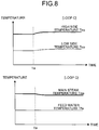
- FIG. 6 to FIG. 9 are respectively diagrams illustrating examples of the monitoring data for the loops A, B, C, and D.
- the high side temperature T ho the low side temperature T co , the main steam temperature T ms , and the feed water temperature T fw , for each of the loops A, B, C, and D are obtained as the monitoring data.
- the horizontal axes represent time and the vertical axes represent temperature.
- the data processing unit 104 assigns the probability distributions derived in Step SP10 to the monitoring data illustrated in FIG. 6 to FIG. 9 (Step SP40).
- the prediction unit 105 inputs the monitoring data that have been assigned with the probability distributions into a stochastic model and predicts a state of the nuclear power plant 200 (Step SP50).
- FIG. 10, FIG. 11 , and FIG. 12 are diagrams illustrating relations between: the breakage diameter R ho of the hot leg 1, the breakage diameter R co of the cold leg 3, and the breakage diameter R cr of the crossover leg 2, as the unobservable state quantity x in the respective loops, the unobservable state quantity x having been predicted by the prediction unit 105; and time.
- a line Lm extending horizontally indicates the central value of the predicted breakage diameter.
- a line Lb branching in a vertical direction from the line Lm indicates a variation (uncertainty) in the predicted breakage diameter.
- the central values of the breakage diameters R ho , R co , and R cr of each loop are predicted to be substantially "0". It can be understood that in this time period before the time point Ta also, the lines Lb are slightly present for the breakage diameters R ho , R co , and R cr of the loop A, and uncertainty is included. This is considered to be because under normal conditions where a loss-of-coolant accident has not occurred, there is also a variation (uncertainty) in the monitoring data of each of the sensors 11, 12, 13, and 14 provided in the loop A, and the probability distribution reflecting the variation has been assigned to the monitoring data. Accordingly, since the probability distribution has been assigned to the monitoring data when the breakage diameter is predicted from the monitoring data under normal conditions also, determination of whether the prediction results indicating that the loop A has broken are highly reliable is able to be made.
- the prediction unit 105 predicts the breakage diameters R ho , R co , and R cr for each loop by using the data resulting from the assignment of the probability distributions to the monitoring data in FIG. 6 to FIG. 9 . Since the hot leg 1 and the cold leg 3 are not broken, as illustrated in FIG. 10 and FIG. 11 , in a time period after the time point Ta, the central values of the breakage diameters R ho and R co are predicted to be substantially "0". It can be understood that in this time period after the time point Ta also, the line Lb is present for the breakage diameters R ho and R co of the loop A, and uncertainty is included. In the example illustrated in FIG.
- the breakage diameters R ho and R co of the loop D do not have a line Lb, but the central values thereof increase slightly. Therefrom, it is predicted that the hot leg 1 and the cold leg 3 of the loop D are likely to break, and it can be said that reliability of this prediction result is high.
- the central value of the breakage diameter R cr of the loop A largely increases at the time point Ta, and it is predicted that the crossover leg 2 of the loop A has broken. It is understood that the breakage diameter R cr of the loop A has a line Lb with a large difference ⁇ L from the central value, and the prediction results have variations.
- the central values of the breakage diameter R cr of the loops B, C, and D increase, and it is predicted that the crossover legs 2 of the loops B, C, and D are likely to break. Reliability of the prediction results is able to be evaluated based on the length (difference ⁇ L) of the line Lb for the breakage diameter R cr of each loop.
- monitoring data that have been assigned with probability distributions are input to a stochastic model (DBNs model); which part of, to what extent, and with a probability of what level, the nuclear power plant 200 is abnormal, are able to be predicted. Further, from prediction results, a degree of uncertainty in the monitoring data and reliability of the prediction results are able to be estimated. Accordingly, in consideration of the uncertainty in the monitoring data and the reliability of the prediction results, the nuclear power plant 200 is able to be operated. Furthermore, if a loss-of-coolant accident occurs, in consideration of the uncertainty in the monitoring data and the reliability of the prediction results, measures are able to be taken or decision making for the measures is able to be performed.
- DBNs model stochastic model
- the monitoring data serving as the basis of the prediction results are able to be evaluated as including uncertainty.
- the time period after the time point Ta also, if the value (length) of a line Lb is large, the reliability of the prediction results is able to be evaluated to be low. Furthermore, if the value of a line Lb before the time point Ta is small and the value of a line Lb after the time point Ta is large, it is able to be evaluated that there is a possibility that the monitoring data obtained after the time point Ta include much uncertainty.
- monitoring data that have been assigned with probability distributions are input into a stochastic model, not only prediction of which part and how much (how many inches) of a piping are broken is possible, but also prediction by association between the degree of breakage and the probability (reliability) is possible, like, for example, a probability that breakage of 5 inches has occurred being found to be A% and a probability that breakage of 4 inches has occurred being found to be B%.
- the identifying unit 102 identifies a probability distribution with a generator output command MWD of the nuclear power plant 200 being an index. Since there is a possibility that the probability distribution changes according to the generator output command MWD; with the generator output command MWD being an index, states of the nuclear power plant 200 corresponding to various generator output commands MWDs are able to be predicted.
- FIG. 13 is a functional block diagram illustrating another example of the plant operation assistance system 100.
- a characteristic point of this embodiment is in that an updating unit 108, which updates the stochastic model with plant parameters identified based on a deterministic model of the plant 200, is included.
- the plant operation assistance system 100 has a determining unit 107 and the updating unit 108.
- the determining unit 107 determines whether or not a probability distribution (an average value and variance) is identifiable. For example, in a time zone, in which the average value and variance largely deviate from actual results of design plan values and past accumulated values of the state quantity y, the determining unit 107 determines that a probability distribution is unidentifiable, and if a difference between the average value and variance, and the design plan values and past accumulated values is small, the determining unit 107 determines that a probability distribution is identifiable.
- An identifiable state means a state where the average value and variance are stable, and that the plant 200 is in a steady state. If it has been determined by the determining unit 107 that a probability distribution is identifiable, that is, if it is determined that the plant 200 is in the steady state, the updating unit 108 identifies plant parameters and updates the stochastic model.
Landscapes
- Engineering & Computer Science (AREA)
- Physics & Mathematics (AREA)
- General Engineering & Computer Science (AREA)
- Plasma & Fusion (AREA)
- High Energy & Nuclear Physics (AREA)
- Automation & Control Theory (AREA)
- General Physics & Mathematics (AREA)
- Chemical & Material Sciences (AREA)
- Chemical Kinetics & Catalysis (AREA)
- Business, Economics & Management (AREA)
- Emergency Management (AREA)
- Testing And Monitoring For Control Systems (AREA)
- Monitoring And Testing Of Nuclear Reactors (AREA)
Abstract
Description
- The present invention relates to a plant operation assistance system and a plant operation assistance method.
- States of plants may be monitored, for determination of current states of the plants based on the monitoring data and existing databases, such as design data, or for prediction of future states of the plants. In
Patent Literature 1, an operation assistance apparatus, which uses a prediction simulator that predicts a future operation state based on monitoring data, is disclosed. InPatent Literature 2 andPatent Literature 3, estimation of parameters by use of a probability theory called "Bayes' theorem" is disclosed. Further, a technique for estimating and visualizing unobserved state quantity by using a deterministic model is disclosed in Non-PatentLiterature 1. - Further, a technique for constructing a diagnostic model for a spacecraft by using a stochastic model called "Dynamic Bayesian Networks, and performing abnormality diagnosis is disclosed in Non-Patent Literature 2.
-
- Patent Literature 1: Japanese Unexamined Patent Application Publication No.
2010-026842 A - Patent Literature 2: Japanese Unexamined Patent Application Publication No.
2003-271231 A - Patent Literature 3: Japanese Unexamined Patent Application Publication No.
2012-009064 A -
- Non-Patent Literature 1: Yokogawa Technical Report, Vol. 56, No. 1 (2013)
- Non-Patent Literature 2: "Spacecraft Diagnosis Method Using Dynamic Bayesian Networks", Journal of Japanese Society for Artificial Intelligence, Vol. 21, No. 1F (2006)
- At the time of emergency, disaster, and the like in a plant, monitoring data of the plant may include much uncertainty, and prediction of a state of the plant may become difficult. In particular, in a case where a deterministic model as disclosed in
Patent Literature 1 and Non-Patent Literature 1 is used, if the monitoring data include uncertainty, reliability of prediction results is reduced. When the plant is operated in reliance on these prediction results, appropriate operation of the plant becomes difficult. - The present invention aims to provide a plant operation assistance system and a plant operation assistance method, which enable prediction of a state of a plant in consideration of uncertainty in monitoring data and assistance in operation of the plant.
- The present invention provides a plant operation assistance system, including a data obtaining unit configured to obtain monitoring data indicating state quantity of a plant, the state quantity being detected by a sensor, an identifying unit configured to identify, based on the state quantity, a probability distribution of the monitoring data, a model generation unit configured to generate, based on a plant parameter composed from a database including design information of the plant, a stochastic model of the plant, a data processing unit configured to assign the probability distribution to the monitoring data obtained by the data obtaining unit, and a prediction unit configured to input the monitoring data assigned with the probability distribution into the stochastic model and predict a state of the plant.
- According to the present invention, since the monitoring data that have been added with the probability distribution are input into the stochastic model; which part of, to what extent, and with a probability of what level, the plant is abnormal, are able to be predicted. Further, from the prediction results, the degree of uncertainty in the monitoring data and the reliability of the prediction results are able to be estimated. Accordingly, in consideration of the uncertainty in the monitoring data and the reliability of the prediction results, the plant is able to be operated.
- In the present invention, it is preferable that the identifying unit is configured to identify the probability distribution with an output command of the plant being an index.
Thereby, states of the plant corresponding to various output commands are able to be predicted. - In the present invention, the plant operation assistance system may include an updating unit configured to update the stochastic model with a plant parameter identified based on a deterministic model of the plant. Thereby, even if the plant parameter is changed, the state of the plant is able to be predicted.
- The present invention provides a plant operation assistance method, including steps of obtaining monitoring data indicating state quantity of a plant, the state quantity being detected by a sensor, identifying, based on the state quantity, a probability distribution of the monitoring data, generating, based on a plant parameter composed from a database including design information of the plant, a stochastic model of the plant, assigning the probability distribution to the obtained monitoring data, and inputting the monitoring data assigned with the probability distribution into the stochastic model and predicting a state of the plant.
- According to the present invention, a state of a plant is able to be predicted appropriately, and the plant is able to be operated in consideration of uncertainty in monitoring data and reliability of prediction results. Advantageous Effects of Invention
- According to the present invention, a plant operation assistance system and a plant operation assistance method, which enable: prediction of a state of a plant in consideration of uncertainty in monitoring data; and assistance in operation of the plant, are provided.
-
-
FIG. 1 is a functional block diagram illustrating an example of a plant operation assistance system according to an embodiment. -
FIG. 2 is a schematic diagram illustrating an example of a plant according to the embodiment. -
FIG. 3 is a diagram for explanation of an example of probability distributions of monitoring data according to the embodiment. -
FIG. 4 is a schematic diagram illustrating an example of a stochastic model according to the embodiment. -
FIG. 5 is a flow chart illustrating an example of a plant operation assistance method according to the embodiment. -
FIG. 6 is a diagram illustrating an example of the monitoring data according to the embodiment. -
FIG. 7 is a diagram illustrating an example of the monitoring data according to the embodiment. -
FIG. 8 is a diagram illustrating an example of the monitoring data according to the embodiment. -
FIG. 9 is a diagram illustrating an example of the monitoring data according to the embodiment. -
FIG. 10 is a diagram illustrating an example of prediction results according to the embodiment. -
FIG. 11 is a diagram illustrating an example of the prediction results according to the embodiment. -
FIG. 12 is a diagram illustrating an example of the prediction results according to the embodiment. -
FIG. 13 is a functional block diagram illustrating another example of the plant operation assistance system according to the embodiment. - Hereinafter, embodiments according to the present invention will be described while reference is made to the drawings, but the present invention is not limited to these embodiments. Components of the respective embodiments described below may be combined with one another, as appropriate. Further, a part of the components may be not used.
-
FIG. 1 is a functional block diagram illustrating an example of a plantoperation assistance system 100 according to an embodiment. The plantoperation assistance system 100 includes a computer system. As illustrated inFIG. 1 , the plantoperation assistance system 100 includes: adata obtaining unit 101 that obtains monitoring data indicating state quantity y of aplant 200, the state quantity y having been detected by asensor 10; an identifyingunit 102 that identifies, based on the state quantity y of theplant 200, a probability distribution of the monitoring data; amodel generation unit 103 that generates, based on a plant parameter composed from a database including design information of theplant 200, a stochastic model of theplant 200; adata processing unit 104 that assigns the probability distribution to the monitoring data obtained by thedata obtaining unit 101; aprediction unit 105 that inputs the monitoring data that have been assigned with the probability distribution, into the stochastic model, and predicts a state of theplant 200; and astorage unit 106 that stores therein data obtained by thedata obtaining unit 101. - The
plant 200 is controlled by acontrol device 300. Thecontrol device 300 includes a computer system, and outputs operation quantity u for operating theplant 100, to the plantoperation assistance system 100 and theplant 200. The state quantity y detected by thesensor 10 is output to the plantoperation assistance system 100 and thecontrol device 300. - An
output command unit 150 is connected to thecontrol device 300. Theoutput command unit 150 has an operation input unit that is operated by an operator, and generates, based on an operation, a command signal. The command signal is an output command signal instructing an output of theplant 200. -
FIG. 2 is a schematic diagram illustrating an example of theplant 200 according to the embodiment. In this embodiment, an example, in which theplant 200 is anuclear power plant 200, will be described.FIG. 2 illustrates anuclear reactor vessel 201 and aprimary cooling system 250, of thenuclear power plant 200. - The
nuclear power plant 200 includes: thenuclear reactor vessel 201 having a reactor core; asteam generator 202; and apressurizer 203 that pressurizes theprimary cooling system 250. Thenuclear reactor vessel 201 heats up primary cooling water. The primary cooling water that has been heated up by thenuclear reactor vessel 201 is sent to thesteam generator 202 via ahot leg 1, which is a high temperature side piping. Thesteam generator 202 generates steam of secondary cooling water by performing heat exchange between the high temperature and high pressure primary cooling water that has been supplied from thenuclear reactor vessel 201 and the secondary cooling water (feed water) that has been supplied from a secondary cooling system. The steam generated by thesteam generator 202 is supplied to a turbine generator (not illustrated) via the secondary cooling system. The primary cooling water that has been cooled in thesteam generator 202 is sent to acold leg 3, which is a low temperature side piping, via acrossover leg 2 and a primarycooling water pump 204, flows through thecold leg 3, and thereafter, is supplied to thenuclear reactor vessel 201. - In this embodiment, the
primary cooling system 250 has four loops (circulation systems), which are a loop A, a loop B, a loop C, and a loop D. The primary cooling water that has been heated up by thenuclear reactor vessel 201 is supplied to each of the loops A, B, C, and D. Each of the loops A, B, C, and D has therein thesteam generator 202, the primarycooling water pump 204, thehot leg 1, thecrossover leg 2, and thecold leg 3. The primary cooling water that has flown through each of the loops A, B, C, and D is returned to thenuclear reactor vessel 201. - In this embodiment, examples of the state quantity y of the
nuclear power plant 200, the state quantity y being observable by use of thesensor 10, include: main steam temperature Tms indicating temperature of the steam of the secondary cooling water generated from thesteam generator 202; feed water temperature Tfw indicating temperature of the secondary cooling water supplied to thesteam generator 202; high side temperature Tho indicating temperature of the primary cooling water flowing through thehot leg 1; low side temperature Tco indicating temperature of the primary cooling water flowing through thecold leg 3; pressure Prcp indicating pressure in theprimary cooling system 250; and flow rate Grcp of the primarycooling water pump 204. - The
sensor 10 includes: a mainsteam temperature sensor 11 that detects the main steam temperature Tms; a feedwater temperature sensor 12 that detects the feed water temperature Tfw; a highside temperature sensor 13 that detects the high side temperature Tho; a lowside temperature sensor 14 that detects the low side temperature Tco; apressure sensor 15 that detects the pressure Prcp; and aflow rate sensor 16 that detects the flow rate Grcp. - The identifying
unit 102 identifies, based on the observable state quantity y of thenuclear power plant 200, a probability distribution of the monitoring data.FIG. 3 is a schematic diagram for explanation of an example of probability distributions of monitoring data. Hereinafter, description will be made by assuming that the state quantity y of thenuclear power plant 200 is the high side temperature Tho. - The identifying
unit 102 statistically derives, based on plural monitoring data (accumulated data) on the high side temperature Tho obtained in a predetermined past time period, a probability distribution for the high side temperature Tho. The predetermined past time period may be, for example, any of: one day; one week; one month; one year; and so on. As the probability distribution, an average value and variance of the high side temperature Tho in the predetermined time period are derived. - Even if the
nuclear power plant 200 is operating normally, the high side temperature Tho may fluctuate. In a predetermined time period when thenuclear power plant 200 is operating normally, the highside temperature sensor 13 monitors the high side temperature Tho, and regularly outputs monitoring data on the high side temperature Tho,
to thedata obtaining unit 101. The monitoring data on the high side temperature Tho, which have been output from the highside temperature sensor 13 and obtained by thedata obtaining unit 101, are accumulated in thestorage unit 106. The identifyingunit 102 derives, based on the plural monitoring data on the high side temperature Tho in the predetermined time period, the plural monitoring data having been stored in thestorage unit 106, an average value and variance of the high side temperature Tho. - In this embodiment, the identifying
unit 102 identifies, with an output command of thenuclear power plant 200 being an index, the probability distribution.
The output command is a generator output command MWD. When the generator output command MWD is changed, an output range of thenuclear power plant 200 is changed, and in association with that change, the average value and variance of the high side temperature Tho are changed. The identifyingunit 102 derives the probability distribution for the high side temperature Tho, for each of plural different generator output commands MWDs. - Graphs illustrated in
FIG. 3 illustrate relations between the high side temperature Tho [°C], the generator output commands MWDs [%], and frequency of obtainment of the monitoring data on the high side temperature Tho. In the example illustrated inFIG. 3 , the average value and variance of the high side temperature Tho at each of the generator output commands MWDs, 0[%], 25[%], 50[%], 75[%], and 100[%], as main operating points of thenuclear power plant 200, have been derived. - An average value and variance of the high side temperature Tho at a generator output command MWD (for example, 60[%]) other than the main operating points may be found, based on the monitoring data, by interpolation.
- The identifying
unit 102 is able to derive, similarly to the probability distribution of the high side temperature Tho, as the observable state quantity y, a probability distribution for the main steam temperature Tms, a probability distribution for the feed water temperature Tfw, a probability distribution for the low side temperature Tco, a probability distribution for the pressure Prcp, and a probability distribution for the flow rate Grcp. Further, the identifyingunit 102 may find a probability distribution for the operation quantity u. - To the
data processing unit 104, a probability distribution identified by the identifyingunit 102 as described by reference toFIG. 3 , and monitoring data of thenuclear power plant 200 obtained by thedata obtaining unit 101 are input. Thedata processing unit 104 assigns the probability distribution to the monitoring data, and sends the monitoring data that have been assigned with the probability distribution, to theprediction unit 105. - The
model generation unit 103 generates, based on plant parameters composed from a database including design information of thenuclear power plant 200, a stochastic model of thenuclear power plant 200. - The plant parameters of the
nuclear power plant 200 are specification data of thenuclear power plant 200, such as design data or characteristic data of devices in thenuclear power plant 200, or physical property data of the primary cooling water. The plant parameters are static known data that are able to be known from these design data. Examples of the plant parameters include, for example: the specific heat of the primary cooling water; and masses, heat transfer coefficients, and heat exchange amounts of the devices in thenuclear power plant 200. - The
model generation unit 103 generates, based on the plant parameters composed from the database including the design information, and on the monitoring data indicating the state quantity y detected by thesensor 10, a stochastic model of thenuclear power plant 200. The stochastic model is a modeling technique that uses a probability theory called "Bayes' theorem". In this embodiment, themodel generation unit 103 generates the stochastic model of thenuclear power plant 200 by using a stochastic model called "Dynamic Bayesian Networks (DBNs)". DBNs is a model obtained by expansion of Bayesian Networks (BNs) so as to be also applicable to a dynamic system, and is said to be a generic state space model encompassing Kalman filter models (KFMs), hidden Markov models (HMMs), and the like. -
FIG. 4 is a schematic diagram illustrating an example of the stochastic model (hereinafter, referred to as a DBNs model) using Dynamic Bayesian Networks (DBNs), and illustrates a graph structure when the system of thenuclear power plant 200 is expressed by DBNs. In a DBNs model, transition distribution of each variable is expressed, and the unobservable state quantity x (hidden variable) at a time point (t-1) and a time point (t) is estimated from the observable state quantity y (variable) at the time point (t-1) and time point (t). InFIG. 4 , the observable state quantity y is shaded values, and the unobservable state quantity x is unshaded values. - In this embodiment, as the unobservable state quantity x, reactor core heating value Qre, heat exchange amount Qsg of the
steam generator 202, flow rate Gho of thehot leg 1, flow rate Gcr of thecrossover leg 2; flow rate Gco of thecold leg 3, breakage diameter Rho of thehot leg 1, breakage diameter Rcr of thecrossover leg 2, breakage diameter Rco of thecold leg 3, masses Msg1, Msg2, Msg3, and Msg4 of thesteam generators 202, and a mass Mcore of the reactor core are estimated. - Hereinafter, an example of the DBNs model will be described. As the observable state quantity y, the main steam temperature Tms of the respective loops A, B, C, and D will be denoted by Tms1, Tms2, Tms3, and Tms4, the feed water temperature Tfw thereof by Tfw1, Tfw2, Tfw3, and Tfw4, the high side temperature Tho thereof by Tho1, Tho2, Tho3, and Tho4, the low side temperature Tco thereof by Tco1, Tco2, Tco3, and Tco4, the flow rate Grcp thereof by Grcp1, Grcp2, Grcp3, and Grcp4, flow rate of the secondary cooling water in the loop A by Gfw1, flow rate of main steam in the loop A by Gms1, water level in the
steam generators 202 of the respective loops A, B, C, and D by Lsg1, Lsg2, Lsg3, and Lsg4, and water level in the reactor core by Lcore. - As the design information (plant parameters), the mass of the reactor core will be denoted by Mcore, the heating value thereof by Qre, the temperature by Tho, and the specific heat by cpho. Further, the masses of the
steam generators 202 of the respective loops A, B, C, and D will be denoted by Msg1, Msg2, Msg3, and Msg4, the heat exchange amount Qsg of thesteam generators 202 thereof by Qsg1, Qsg2, Qsg3, and Qsg4, the specific heat of the primary cooling water in thehot legs 1 thereof by cpho1, cpho2, cpho3, and cpho4, and the specific heat of the primary cooling water in thecold legs 3 thereof by cpco1, cpco2, cpco3, and cpco4. - As an example of the DBNs model of the
nuclear power plant 200, a part of thenuclear power plant 200 is able to be expressed by the following differential equations, Equation (1) to Equation (5).


- Further, as examples of the unobservable state quantity x, the heating value Qre of the reactor core and the heat exchange amount Qsg1 of the
steam generator 202 are able to be expressed by the following Equation (6) and Equation (7).

- As expressed by Equation (6) and Equation (7), the heating value Qre and the heat exchange amount Qsg1 are expressed as functions of the generator output command MWD and the like.
- Further, in the DBNs model, a conditional probability Pr is assigned to all of the variables. For example, for Tcol,t, with Tco1,t-1, Tho1,t-1, Grcp1,t-1, and Qsg1,t-1 being parent variables, a conditional probability like Equation (8) is assigned.

- In Equation (8), ∑ is a variance matrix of a normal distribution. In Equation (8), "Qsg1,t-1, ∑" is a parameter that is variable according to the generator output command MWD. By the DBNs model being made variable by the generator output command MWD, the DBNs model becomes a model, in which variation differences among the monitoring data according to the generator output commands MWDs are able to be considered.
- The monitoring data that have been assigned with the probability distribution generated by the
data processing unit 104, and the DBNs model that has been generated by themodel generation unit 103 are input to theprediction unit 105. Theprediction unit 105 inputs the monitoring data that have been assigned with the probability distribution, into the DBNs model, and outputs the unobservable state quantity x. Since the monitoring data that have been assigned with the probability distribution are input into the DBNs model, the degree of variation in the predicted state quantity x is able to be found. - Next, an example of a plant operation assistance method according to this embodiment will be described.
FIG. 5 is a flow chart illustrating the example of the plant operation assistance method according to this embodiment. - In the following description, an example, in which a loss-of-coolant accident (LOCA) occurs in the
nuclear power plant 200 and in which part of the loops A, B, C, and D breakage of a piping (leg) has occurred is estimated, will be described. - Based on plural monitoring data (accumulated data) obtained by use of the
sensor 10 in a predetermined past time period, a probability distribution for those monitoring data is identified (Step SP10). The identifyingunit 102 identifies at least probability distributions of the high side temperature Tho, the low side temperature Tco, the main steam temperature Tms, and the feed water temperature Tfw, for each of the loops A, B, C, and D. - The
model generation unit 103 generates a DBNs model, based on plant parameters (Step SP20). - Monitoring data for the
nuclear power plant 200 are obtained (Step SP30).FIG. 6 to FIG. 9 are respectively diagrams illustrating examples of the monitoring data for the loops A, B, C, and D. As illustrated inFIG. 6 to FIG. 9 , the high side temperature Tho, the low side temperature Tco, the main steam temperature Tms, and the feed water temperature Tfw, for each of the loops A, B, C, and D are obtained as the monitoring data. In the graphs ofFIG. 6 to FIG. 9 , the horizontal axes represent time and the vertical axes represent temperature. - For example, if the
crossover leg 2 of the loop A is broken and a loss-of-coolant accident occurs at a time point Ta, a phenomenon, in which the pressure loss in thecrossover leg 2 is reduced, the flow rate of the primary cooling water flowing through thehot leg 1 is increased, and as illustrated inFIG. 6 , the high side temperature Tho is increased, occurs. Further, when the flow rate of the primary cooling water flowing through thehot leg 1 is increased, as illustrated inFIG. 6 , a phenomenon, in which the low side temperature Tco and the main steam temperature Tms are increased, occurs. - Since the primary cooling water flowing in each loop collects at the
nuclear reactor vessel 201, and is thereafter supplied to each loop, the temperature in each of the loops B, C, and D also changes as illustrated inFIG. 7 to FIG. 9 , due to the breakage of thecrossover leg 2 of the loop A. - The
data processing unit 104 assigns the probability distributions derived in Step SP10 to the monitoring data illustrated inFIG. 6 to FIG. 9 (Step SP40). - The
prediction unit 105 inputs the monitoring data that have been assigned with the probability distributions into a stochastic model and predicts a state of the nuclear power plant 200 (Step SP50). -
FIG. 10, FIG. 11 , andFIG. 12 are diagrams illustrating relations between: the breakage diameter Rho of thehot leg 1, the breakage diameter Rco of thecold leg 3, and the breakage diameter Rcr of thecrossover leg 2, as the unobservable state quantity x in the respective loops, the unobservable state quantity x having been predicted by theprediction unit 105; and time. - In each of
FIG. 10 to FIG. 12 , a line Lm extending horizontally indicates the central value of the predicted breakage diameter. A line Lb branching in a vertical direction from the line Lm indicates a variation (uncertainty) in the predicted breakage diameter. - As illustrated in
FIG. 10 to FIG. 12 , in a time period before the time point Ta, at which the loss-of-coolant accident occurs, the central values of the breakage diameters Rho, Rco, and Rcr of each loop are predicted to be substantially "0". It can be understood that in this time period before the time point Ta also, the lines Lb are slightly present for the breakage diameters Rho, Rco, and Rcr of the loop A, and uncertainty is included. This is considered to be because under normal conditions where a loss-of-coolant accident has not occurred, there is also a variation (uncertainty) in the monitoring data of each of thesensors - In the case where the
crossover leg 2 of the loop A breaks and the loss-of-coolant accident occurs at the time point Ta, theprediction unit 105 predicts the breakage diameters Rho, Rco, and Rcr for each loop by using the data resulting from the assignment of the probability distributions to the monitoring data inFIG. 6 to FIG. 9 . Since thehot leg 1 and thecold leg 3 are not broken, as illustrated inFIG. 10 and FIG. 11 , in a time period after the time point Ta, the central values of the breakage diameters Rho and Rco are predicted to be substantially "0". It can be understood that in this time period after the time point Ta also, the line Lb is present for the breakage diameters Rho and Rco of the loop A, and uncertainty is included. In the example illustrated inFIG. 10 , when a difference between the maximum value or minimum value of the line Lb and the central value indicated by the line Lm is ΔL, it is predicted that there is a possibility that breakage with the breakage diameter Rho of the loop A in a range of "central value ± ΔL" has occurred. As described above, with a variation (uncertainty), the breakage diameter Rho in the loop A is predicted. In the example illustrated inFIG. 10 , the minimum value of the line Lb is less than "0". Therefore, reliability of the prediction results for the breakage diameter Rho of the loop A is evaluated to be low. - Further, in the example illustrated in
FIG. 10 and FIG. 11 , the breakage diameters Rho and Rco of the loop D do not have a line Lb, but the central values thereof increase slightly. Therefrom, it is predicted that thehot leg 1 and thecold leg 3 of the loop D are likely to break, and it can be said that reliability of this prediction result is high. - As illustrated in
FIG. 12 , the central value of the breakage diameter Rcr of the loop A largely increases at the time point Ta, and it is predicted that thecrossover leg 2 of the loop A has broken. It is understood that the breakage diameter Rcr of the loop A has a line Lb with a large difference ΔL from the central value, and the prediction results have variations. - Further, in the time period after the time point Ta, the central values of the breakage diameter Rcr of the loops B, C, and D increase, and it is predicted that the
crossover legs 2 of the loops B, C, and D are likely to break. Reliability of the prediction results is able to be evaluated based on the length (difference ΔL) of the line Lb for the breakage diameter Rcr of each loop. - As described above, according to this embodiment, since monitoring data that have been assigned with probability distributions are input to a stochastic model (DBNs model); which part of, to what extent, and with a probability of what level, the
nuclear power plant 200 is abnormal, are able to be predicted. Further, from prediction results, a degree of uncertainty in the monitoring data and reliability of the prediction results are able to be estimated. Accordingly, in consideration of the uncertainty in the monitoring data and the reliability of the prediction results, thenuclear power plant 200 is able to be operated. Furthermore, if a loss-of-coolant accident occurs, in consideration of the uncertainty in the monitoring data and the reliability of the prediction results, measures are able to be taken or decision making for the measures is able to be performed. - That is, as illustrated in
FIG. 10 , if a prediction result, which indicates that in the time period before the time point Ta, the breakage diameter Rho of the loop A includes a line Lb, is obtained, the monitoring data serving as the basis of the prediction results are able to be evaluated as including uncertainty. - Further, in the time period after the time point Ta also, if the value (length) of a line Lb is large, the reliability of the prediction results is able to be evaluated to be low. Furthermore, if the value of a line Lb before the time point Ta is small and the value of a line Lb after the time point Ta is large, it is able to be evaluated that there is a possibility that the monitoring data obtained after the time point Ta include much uncertainty.
- In a conventional method, in which monitoring data not assigned with a probability distribution are input to a deterministic model; which part and how much (how many inches) of a piping is broken are able to be predicted. However, reliability of the prediction results is difficult to be evaluated.
- In this embodiment, since monitoring data that have been assigned with probability distributions are input into a stochastic model, not only prediction of which part and how much (how many inches) of a piping are broken is possible, but also prediction by association between the degree of breakage and the probability (reliability) is possible, like, for example, a probability that breakage of 5 inches has occurred being found to be A% and a probability that breakage of 4 inches has occurred being found to be B%.
- Further, in this embodiment, the identifying
unit 102 identifies a probability distribution with a generator output command MWD of thenuclear power plant 200 being an index. Since there is a possibility that the probability distribution changes according to the generator output command MWD; with the generator output command MWD being an index, states of thenuclear power plant 200 corresponding to various generator output commands MWDs are able to be predicted. -
FIG. 13 is a functional block diagram illustrating another example of the plantoperation assistance system 100. A characteristic point of this embodiment is in that an updatingunit 108, which updates the stochastic model with plant parameters identified based on a deterministic model of theplant 200, is included. - As illustrated in
FIG. 13 , the plantoperation assistance system 100 has a determiningunit 107 and the updatingunit 108. In the determiningunit 107, whether or not a probability distribution (an average value and variance) is identifiable is determined. For example, in a time zone, in which the average value and variance largely deviate from actual results of design plan values and past accumulated values of the state quantity y, the determiningunit 107 determines that a probability distribution is unidentifiable, and if a difference between the average value and variance, and the design plan values and past accumulated values is small, the determiningunit 107 determines that a probability distribution is identifiable. - An identifiable state means a state where the average value and variance are stable, and that the
plant 200 is in a steady state. If it has been determined by the determiningunit 107 that a probability distribution is identifiable, that is, if it is determined that theplant 200 is in the steady state, the updatingunit 108 identifies plant parameters and updates the stochastic model. - The updating
unit 108 generates a deterministic model of theplant 200. Further, the state quantity y and operation quantity u of theplant 200 are input to the updatingunit 108. By inputting the state quantity y and the operation quantity u into the deterministic model that has been modelled, the updatingunit 108 identifies plant parameters of theplant 200 by fitting. - The plant parameters newly identified by the updating
unit 108 are sent to themodel generation unit 103. Themodel generation unit 103 updates the stochastic model with the plant parameters that have been identified based on the deterministic model of theplant 200. - Although the plant parameters are static data, the plant parameters may change. According to this embodiment, since plant parameters are identified based on a deterministic model of the
plant 200, and a stochastic model is regenerated with these identified new plant parameters, a state of theplant 200 is able to be predicted appropriately even if the plant parameters are changed. - In the above described embodiment, a probability distribution is derived based on plural monitoring data (accumulated data) obtained in a predetermined past time period. If past accumulated data are not available, like when the
plant 200 is newly established, a probability distribution of monitoring data may be derived based on, for example, specification data of thesensor 10. -
- 1
- HOT LEG
- 2
- CROSSOVER LEG
- 3
- COLD LEG
- 10
- SENSOR
- 11
- MAIN STEAM TEMPERATURE SENSOR
- 12
- FEED WATER TEMPERATURE SENSOR
- 13
- HIGH SIDE TEMPERATURE SENSOR
- 14
- LOW SIDE TEMPERATURE SENSOR
- 15
- PRESSURE SENSOR
- 16
- FLOW RATE SENSOR
- 100
- PLANT OPERATION ASSISTANCE SYSTEM
- 101
- DATA OBTAINING UNIT
- 102
- IDENTIFYING UNIT
- 103
- MODEL GENERATION UNIT
- 104
- DATA PROCESSING UNIT
- 105
- PREDICTION UNIT
- 106
- STORAGE UNIT
- 107
- DETERMINING UNIT
- 108
- UPDATING UNIT
- 150
- OUTPUT COMMAND UNIT
- 200
- PLANT (NUCLEAR POWER PLANT)
- 201
- NUCLEAR REACTOR VESSEL
- 202
- STEAM GENERATOR
- 203
- PRESSURIZER
- 204
- PRIMARY COOLING WATER PUMP
- 250
- PRIMARY COOLING SYSTEM
- 300
- CONTROL DEVICE
- Tms
- MAIN STEAM TEMPERATURE
- Tfw
- FEED WATER TEMPERATURE
- Tho
- HIGH SIDE TEMPERATURE
- Tco
- LOW SIDE TEMPERATURE
- Prcp
- PRESSURE
- Grcp
- FLOW RATE
Claims (4)
- A plant operation assistance system, comprising:a data obtaining unit configured to obtain monitoring data indicating state quantity of a plant, the state quantity being detected by a sensor;an identifying unit configured to identify, based on the state quantity, a probability distribution of the monitoring data;a model generation unit configured to generate, based on a plant parameter composed from a database including design information of the plant, a stochastic model of the plant;a data processing unit configured to assign the probability distribution to the monitoring data obtained by the data obtaining unit; anda prediction unit configured to input the monitoring data assigned with the probability distribution into the stochastic model and predict a state of the plant.
- The plant operation assistance system according to claim 1, wherein the identifying unit is configured to identify the probability distribution with an output command of the plant being an index.
- The plant operation assistance system according to claim 1 or claim 2, comprising an updating unit configured to update the stochastic model with a plant parameter identified based on a deterministic model of the plant.
- A plant operation assistance method, including steps of:obtaining monitoring data indicating state quantity of a plant, the state quantity being detected by a sensor;identifying, based on the state quantity, a probability distribution of the monitoring data;generating, based on a plant parameter composed from a database including design information of the plant, a stochastic model of the plant;assigning the probability distribution to the obtained monitoring data; andinputting the monitoring data assigned with the probability distribution into the stochastic model and predicting a state of the plant.
Applications Claiming Priority (2)
| Application Number | Priority Date | Filing Date | Title |
|---|---|---|---|
| JP2015035664A JP6246755B2 (en) | 2015-02-25 | 2015-02-25 | Plant operation support system and plant operation support method |
| PCT/JP2016/051542 WO2016136337A1 (en) | 2015-02-25 | 2016-01-20 | Plant operation assistance system and plant operation assistance method |
Publications (3)
| Publication Number | Publication Date |
|---|---|
| EP3260942A1 true EP3260942A1 (en) | 2017-12-27 |
| EP3260942A4 EP3260942A4 (en) | 2018-10-31 |
| EP3260942B1 EP3260942B1 (en) | 2020-07-22 |
Family
ID=56789364
Family Applications (1)
| Application Number | Title | Priority Date | Filing Date |
|---|---|---|---|
| EP16755087.0A Active EP3260942B1 (en) | 2015-02-25 | 2016-01-20 | Plant operation assistance system and plant operation assistance method |
Country Status (4)
| Country | Link |
|---|---|
| US (1) | US20180247721A1 (en) |
| EP (1) | EP3260942B1 (en) |
| JP (1) | JP6246755B2 (en) |
| WO (1) | WO2016136337A1 (en) |
Cited By (2)
| Publication number | Priority date | Publication date | Assignee | Title |
|---|---|---|---|---|
| JP2020021292A (en) * | 2018-08-01 | 2020-02-06 | ルネサスエレクトロニクス株式会社 | Information processing apparatus, information processing system, and program |
| EP3767560A4 (en) * | 2018-03-14 | 2021-11-24 | Hitachi, Ltd. | FUTURE STATE ESTIMATION AND FUTURE STATE ESTIMATION PROCESS |
Families Citing this family (5)
| Publication number | Priority date | Publication date | Assignee | Title |
|---|---|---|---|---|
| JP7444426B2 (en) * | 2019-09-12 | 2024-03-06 | 地方独立行政法人東京都立産業技術研究センター | State estimation evaluation device, method, and program |
| US12106865B2 (en) * | 2020-05-18 | 2024-10-01 | Oregon State University | Method and apparatus for real-time learning-based augmented irradiation control and optimization |
| JP7454775B2 (en) | 2020-07-31 | 2024-03-25 | 三菱重工サーマルシステムズ株式会社 | Abnormality diagnosis device, abnormality diagnosis method, and program |
| CN112130998B (en) * | 2020-09-23 | 2022-02-01 | 中国核动力研究设计院 | Optimization method of nuclear reactor system analysis program suitable for multi-loop pressurized water reactor |
| KR102797663B1 (en) * | 2023-03-30 | 2025-04-17 | 한국수력원자력 주식회사 | Prediction diagnosis method and system nuclear power plant equipment |
Family Cites Families (6)
| Publication number | Priority date | Publication date | Assignee | Title |
|---|---|---|---|---|
| JP3968656B2 (en) * | 2003-02-05 | 2007-08-29 | 株式会社日立製作所 | Maintenance support device for plant equipment |
| JP2007240464A (en) * | 2006-03-10 | 2007-09-20 | Toshiba Corp | Boiling water reactor core condition monitoring device |
| US8473435B2 (en) * | 2010-03-09 | 2013-06-25 | Schlumberger Technology Corporation | Use of general bayesian networks in oilfield operations |
| GB2481782A (en) * | 2010-06-21 | 2012-01-11 | Optimized Systems And Solutions Ltd | Asset health monitoring |
| WO2012013210A1 (en) * | 2010-07-30 | 2012-02-02 | Abb Technology Ag | Method and system for identification of indexes, for distributed control systems |
| JP6464447B2 (en) * | 2013-09-02 | 2019-02-06 | 本田技研工業株式会社 | Observation value prediction apparatus and observation value prediction method |
-
2015
- 2015-02-25 JP JP2015035664A patent/JP6246755B2/en active Active
-
2016
- 2016-01-20 US US15/553,001 patent/US20180247721A1/en not_active Abandoned
- 2016-01-20 WO PCT/JP2016/051542 patent/WO2016136337A1/en not_active Ceased
- 2016-01-20 EP EP16755087.0A patent/EP3260942B1/en active Active
Cited By (3)
| Publication number | Priority date | Publication date | Assignee | Title |
|---|---|---|---|---|
| EP3767560A4 (en) * | 2018-03-14 | 2021-11-24 | Hitachi, Ltd. | FUTURE STATE ESTIMATION AND FUTURE STATE ESTIMATION PROCESS |
| US11573541B2 (en) | 2018-03-14 | 2023-02-07 | Hitachi, Ltd. | Future state estimation device and future state estimation method |
| JP2020021292A (en) * | 2018-08-01 | 2020-02-06 | ルネサスエレクトロニクス株式会社 | Information processing apparatus, information processing system, and program |
Also Published As
| Publication number | Publication date |
|---|---|
| JP2016157329A (en) | 2016-09-01 |
| EP3260942A4 (en) | 2018-10-31 |
| WO2016136337A1 (en) | 2016-09-01 |
| US20180247721A1 (en) | 2018-08-30 |
| JP6246755B2 (en) | 2017-12-13 |
| EP3260942B1 (en) | 2020-07-22 |
Similar Documents
| Publication | Publication Date | Title |
|---|---|---|
| EP3260942B1 (en) | Plant operation assistance system and plant operation assistance method | |
| Ji et al. | Prognostics enabled resilient control for model-based building automation systems | |
| US10018979B2 (en) | Device and method for detection and/or diagnosis of faults in a processes, equipment and sensors | |
| EP3299918A1 (en) | Abnormality diagnosis system and abnormality diagnosis method | |
| Catelani et al. | Sensitivity analysis with MC simulation for the failure rate evaluation and reliability assessment | |
| Hu et al. | DBN based failure prognosis method considering the response of protective layers for the complex industrial systems | |
| Maul et al. | Sensor selection and optimization for health assessment of aerospace systems | |
| Hassnain et al. | Available recovery time prediction in case of an accident scenario for NPP component | |
| Taleb-Berrouane et al. | Dynamic RAMS analysis using advanced probabilistic approach | |
| Ramuhalli et al. | Uncertainty quantification techniques for sensor calibration monitoring in nuclear power plants | |
| Syrotkina et al. | Evaluation to determine the efficiency for the diagnosis search formation method of failures in automated systems | |
| Asim Abbasi et al. | Development of a fault diagnostics and tolerance system: An application to continuous stirred tank reactor | |
| US10733331B2 (en) | Information processing apparatus, information processing method, and recording medium | |
| Dalapatu et al. | Alarm allocation for event-based process alarm systems | |
| Kim et al. | A Survey of data-based human reliability analysis approaches | |
| Tamssaouet et al. | Uncertainty quantification in system-level prognostics: application to Tennessee Eastman process | |
| Alamaniotis et al. | Probabilistic kernel approach to online monitoring of nuclear power plants | |
| CN118169510A (en) | A distribution network fault location method and system based on artificial intelligence | |
| Ravinder | Experience in asset performance management analytics for decision support on Transmission & Distribution Assets | |
| KR20230071334A (en) | Apparatus and method for determining abnormalities in calorimeter | |
| Williams et al. | Evaluating the role of building thermal inertia for the provision of decentralised demand side primary electrical frequency regulation services | |
| Bernardi | Fault-tolerant Model-based Predictive Control Applied to Industrial Processes | |
| Madsen et al. | A methodology for developing local smart diagnostic models using expert knowledge | |
| Tuinema et al. | Reliability models of components | |
| Bernardi | Doctor en Tecnologıa Quımica |
Legal Events
| Date | Code | Title | Description |
|---|---|---|---|
| STAA | Information on the status of an ep patent application or granted ep patent |
Free format text: STATUS: THE INTERNATIONAL PUBLICATION HAS BEEN MADE |
|
| PUAI | Public reference made under article 153(3) epc to a published international application that has entered the european phase |
Free format text: ORIGINAL CODE: 0009012 |
|
| STAA | Information on the status of an ep patent application or granted ep patent |
Free format text: STATUS: REQUEST FOR EXAMINATION WAS MADE |
|
| 17P | Request for examination filed |
Effective date: 20170824 |
|
| AK | Designated contracting states |
Kind code of ref document: A1 Designated state(s): AL AT BE BG CH CY CZ DE DK EE ES FI FR GB GR HR HU IE IS IT LI LT LU LV MC MK MT NL NO PL PT RO RS SE SI SK SM TR |
|
| AX | Request for extension of the european patent |
Extension state: BA ME |
|
| DAV | Request for validation of the european patent (deleted) | ||
| DAX | Request for extension of the european patent (deleted) | ||
| A4 | Supplementary search report drawn up and despatched |
Effective date: 20181001 |
|
| RIC1 | Information provided on ipc code assigned before grant |
Ipc: G05B 17/02 20060101ALI20180925BHEP Ipc: G21C 17/00 20060101ALI20180925BHEP Ipc: G05B 23/02 20060101AFI20180925BHEP |
|
| STAA | Information on the status of an ep patent application or granted ep patent |
Free format text: STATUS: EXAMINATION IS IN PROGRESS |
|
| 17Q | First examination report despatched |
Effective date: 20190510 |
|
| GRAP | Despatch of communication of intention to grant a patent |
Free format text: ORIGINAL CODE: EPIDOSNIGR1 |
|
| STAA | Information on the status of an ep patent application or granted ep patent |
Free format text: STATUS: GRANT OF PATENT IS INTENDED |
|
| INTG | Intention to grant announced |
Effective date: 20200331 |
|
| RAP1 | Party data changed (applicant data changed or rights of an application transferred) |
Owner name: MITSUBISHI HEAVY INDUSTRIES, LTD. |
|
| RIN1 | Information on inventor provided before grant (corrected) |
Inventor name: ONO, HITOI Inventor name: HANADA, SATOSHI Inventor name: NODA, EISUKE |
|
| GRAS | Grant fee paid |
Free format text: ORIGINAL CODE: EPIDOSNIGR3 |
|
| GRAA | (expected) grant |
Free format text: ORIGINAL CODE: 0009210 |
|
| STAA | Information on the status of an ep patent application or granted ep patent |
Free format text: STATUS: THE PATENT HAS BEEN GRANTED |
|
| AK | Designated contracting states |
Kind code of ref document: B1 Designated state(s): AL AT BE BG CH CY CZ DE DK EE ES FI FR GB GR HR HU IE IS IT LI LT LU LV MC MK MT NL NO PL PT RO RS SE SI SK SM TR |
|
| REG | Reference to a national code |
Ref country code: GB Ref legal event code: FG4D |
|
| REG | Reference to a national code |
Ref country code: CH Ref legal event code: EP |
|
| REG | Reference to a national code |
Ref country code: DE Ref legal event code: R096 Ref document number: 602016040425 Country of ref document: DE |
|
| REG | Reference to a national code |
Ref country code: AT Ref legal event code: REF Ref document number: 1293997 Country of ref document: AT Kind code of ref document: T Effective date: 20200815 |
|
| REG | Reference to a national code |
Ref country code: IE Ref legal event code: FG4D |
|
| REG | Reference to a national code |
Ref country code: LT Ref legal event code: MG4D |
|
| REG | Reference to a national code |
Ref country code: AT Ref legal event code: MK05 Ref document number: 1293997 Country of ref document: AT Kind code of ref document: T Effective date: 20200722 |
|
| PG25 | Lapsed in a contracting state [announced via postgrant information from national office to epo] |
Ref country code: FI Free format text: LAPSE BECAUSE OF FAILURE TO SUBMIT A TRANSLATION OF THE DESCRIPTION OR TO PAY THE FEE WITHIN THE PRESCRIBED TIME-LIMIT Effective date: 20200722 Ref country code: SE Free format text: LAPSE BECAUSE OF FAILURE TO SUBMIT A TRANSLATION OF THE DESCRIPTION OR TO PAY THE FEE WITHIN THE PRESCRIBED TIME-LIMIT Effective date: 20200722 Ref country code: NO Free format text: LAPSE BECAUSE OF FAILURE TO SUBMIT A TRANSLATION OF THE DESCRIPTION OR TO PAY THE FEE WITHIN THE PRESCRIBED TIME-LIMIT Effective date: 20201022 Ref country code: GR Free format text: LAPSE BECAUSE OF FAILURE TO SUBMIT A TRANSLATION OF THE DESCRIPTION OR TO PAY THE FEE WITHIN THE PRESCRIBED TIME-LIMIT Effective date: 20201023 Ref country code: BG Free format text: LAPSE BECAUSE OF FAILURE TO SUBMIT A TRANSLATION OF THE DESCRIPTION OR TO PAY THE FEE WITHIN THE PRESCRIBED TIME-LIMIT Effective date: 20201022 Ref country code: ES Free format text: LAPSE BECAUSE OF FAILURE TO SUBMIT A TRANSLATION OF THE DESCRIPTION OR TO PAY THE FEE WITHIN THE PRESCRIBED TIME-LIMIT Effective date: 20200722 Ref country code: AT Free format text: LAPSE BECAUSE OF FAILURE TO SUBMIT A TRANSLATION OF THE DESCRIPTION OR TO PAY THE FEE WITHIN THE PRESCRIBED TIME-LIMIT Effective date: 20200722 Ref country code: HR Free format text: LAPSE BECAUSE OF FAILURE TO SUBMIT A TRANSLATION OF THE DESCRIPTION OR TO PAY THE FEE WITHIN THE PRESCRIBED TIME-LIMIT Effective date: 20200722 Ref country code: PT Free format text: LAPSE BECAUSE OF FAILURE TO SUBMIT A TRANSLATION OF THE DESCRIPTION OR TO PAY THE FEE WITHIN THE PRESCRIBED TIME-LIMIT Effective date: 20201123 Ref country code: LT Free format text: LAPSE BECAUSE OF FAILURE TO SUBMIT A TRANSLATION OF THE DESCRIPTION OR TO PAY THE FEE WITHIN THE PRESCRIBED TIME-LIMIT Effective date: 20200722 |
|
| PG25 | Lapsed in a contracting state [announced via postgrant information from national office to epo] |
Ref country code: IS Free format text: LAPSE BECAUSE OF FAILURE TO SUBMIT A TRANSLATION OF THE DESCRIPTION OR TO PAY THE FEE WITHIN THE PRESCRIBED TIME-LIMIT Effective date: 20201122 Ref country code: PL Free format text: LAPSE BECAUSE OF FAILURE TO SUBMIT A TRANSLATION OF THE DESCRIPTION OR TO PAY THE FEE WITHIN THE PRESCRIBED TIME-LIMIT Effective date: 20200722 Ref country code: RS Free format text: LAPSE BECAUSE OF FAILURE TO SUBMIT A TRANSLATION OF THE DESCRIPTION OR TO PAY THE FEE WITHIN THE PRESCRIBED TIME-LIMIT Effective date: 20200722 Ref country code: LV Free format text: LAPSE BECAUSE OF FAILURE TO SUBMIT A TRANSLATION OF THE DESCRIPTION OR TO PAY THE FEE WITHIN THE PRESCRIBED TIME-LIMIT Effective date: 20200722 |
|
| PG25 | Lapsed in a contracting state [announced via postgrant information from national office to epo] |
Ref country code: NL Free format text: LAPSE BECAUSE OF FAILURE TO SUBMIT A TRANSLATION OF THE DESCRIPTION OR TO PAY THE FEE WITHIN THE PRESCRIBED TIME-LIMIT Effective date: 20200722 |
|
| REG | Reference to a national code |
Ref country code: DE Ref legal event code: R097 Ref document number: 602016040425 Country of ref document: DE |
|
| PG25 | Lapsed in a contracting state [announced via postgrant information from national office to epo] |
Ref country code: DK Free format text: LAPSE BECAUSE OF FAILURE TO SUBMIT A TRANSLATION OF THE DESCRIPTION OR TO PAY THE FEE WITHIN THE PRESCRIBED TIME-LIMIT Effective date: 20200722 Ref country code: CZ Free format text: LAPSE BECAUSE OF FAILURE TO SUBMIT A TRANSLATION OF THE DESCRIPTION OR TO PAY THE FEE WITHIN THE PRESCRIBED TIME-LIMIT Effective date: 20200722 Ref country code: RO Free format text: LAPSE BECAUSE OF FAILURE TO SUBMIT A TRANSLATION OF THE DESCRIPTION OR TO PAY THE FEE WITHIN THE PRESCRIBED TIME-LIMIT Effective date: 20200722 Ref country code: SM Free format text: LAPSE BECAUSE OF FAILURE TO SUBMIT A TRANSLATION OF THE DESCRIPTION OR TO PAY THE FEE WITHIN THE PRESCRIBED TIME-LIMIT Effective date: 20200722 Ref country code: EE Free format text: LAPSE BECAUSE OF FAILURE TO SUBMIT A TRANSLATION OF THE DESCRIPTION OR TO PAY THE FEE WITHIN THE PRESCRIBED TIME-LIMIT Effective date: 20200722 Ref country code: IT Free format text: LAPSE BECAUSE OF FAILURE TO SUBMIT A TRANSLATION OF THE DESCRIPTION OR TO PAY THE FEE WITHIN THE PRESCRIBED TIME-LIMIT Effective date: 20200722 |
|
| PLBE | No opposition filed within time limit |
Free format text: ORIGINAL CODE: 0009261 |
|
| STAA | Information on the status of an ep patent application or granted ep patent |
Free format text: STATUS: NO OPPOSITION FILED WITHIN TIME LIMIT |
|
| PG25 | Lapsed in a contracting state [announced via postgrant information from national office to epo] |
Ref country code: AL Free format text: LAPSE BECAUSE OF FAILURE TO SUBMIT A TRANSLATION OF THE DESCRIPTION OR TO PAY THE FEE WITHIN THE PRESCRIBED TIME-LIMIT Effective date: 20200722 |
|
| 26N | No opposition filed |
Effective date: 20210423 |
|
| PG25 | Lapsed in a contracting state [announced via postgrant information from national office to epo] |
Ref country code: SK Free format text: LAPSE BECAUSE OF FAILURE TO SUBMIT A TRANSLATION OF THE DESCRIPTION OR TO PAY THE FEE WITHIN THE PRESCRIBED TIME-LIMIT Effective date: 20200722 |
|
| REG | Reference to a national code |
Ref country code: DE Ref legal event code: R119 Ref document number: 602016040425 Country of ref document: DE |
|
| PG25 | Lapsed in a contracting state [announced via postgrant information from national office to epo] |
Ref country code: SI Free format text: LAPSE BECAUSE OF FAILURE TO SUBMIT A TRANSLATION OF THE DESCRIPTION OR TO PAY THE FEE WITHIN THE PRESCRIBED TIME-LIMIT Effective date: 20200722 Ref country code: MC Free format text: LAPSE BECAUSE OF FAILURE TO SUBMIT A TRANSLATION OF THE DESCRIPTION OR TO PAY THE FEE WITHIN THE PRESCRIBED TIME-LIMIT Effective date: 20200722 |
|
| REG | Reference to a national code |
Ref country code: CH Ref legal event code: PL |
|
| GBPC | Gb: european patent ceased through non-payment of renewal fee |
Effective date: 20210120 |
|
| PG25 | Lapsed in a contracting state [announced via postgrant information from national office to epo] |
Ref country code: LU Free format text: LAPSE BECAUSE OF NON-PAYMENT OF DUE FEES Effective date: 20210120 |
|
| REG | Reference to a national code |
Ref country code: BE Ref legal event code: MM Effective date: 20210131 Ref country code: NL Ref legal event code: MP Effective date: 20200722 |
|
| PG25 | Lapsed in a contracting state [announced via postgrant information from national office to epo] |
Ref country code: DE Free format text: LAPSE BECAUSE OF NON-PAYMENT OF DUE FEES Effective date: 20210803 Ref country code: CH Free format text: LAPSE BECAUSE OF NON-PAYMENT OF DUE FEES Effective date: 20210131 Ref country code: LI Free format text: LAPSE BECAUSE OF NON-PAYMENT OF DUE FEES Effective date: 20210131 Ref country code: GB Free format text: LAPSE BECAUSE OF NON-PAYMENT OF DUE FEES Effective date: 20210120 |
|
| PG25 | Lapsed in a contracting state [announced via postgrant information from national office to epo] |
Ref country code: IE Free format text: LAPSE BECAUSE OF NON-PAYMENT OF DUE FEES Effective date: 20210120 |
|
| PG25 | Lapsed in a contracting state [announced via postgrant information from national office to epo] |
Ref country code: IS Free format text: LAPSE BECAUSE OF FAILURE TO SUBMIT A TRANSLATION OF THE DESCRIPTION OR TO PAY THE FEE WITHIN THE PRESCRIBED TIME-LIMIT Effective date: 20201122 |
|
| PG25 | Lapsed in a contracting state [announced via postgrant information from national office to epo] |
Ref country code: BE Free format text: LAPSE BECAUSE OF NON-PAYMENT OF DUE FEES Effective date: 20210131 |
|
| P01 | Opt-out of the competence of the unified patent court (upc) registered |
Effective date: 20230522 |
|
| PG25 | Lapsed in a contracting state [announced via postgrant information from national office to epo] |
Ref country code: CY Free format text: LAPSE BECAUSE OF FAILURE TO SUBMIT A TRANSLATION OF THE DESCRIPTION OR TO PAY THE FEE WITHIN THE PRESCRIBED TIME-LIMIT Effective date: 20200722 |
|
| PG25 | Lapsed in a contracting state [announced via postgrant information from national office to epo] |
Ref country code: HU Free format text: LAPSE BECAUSE OF FAILURE TO SUBMIT A TRANSLATION OF THE DESCRIPTION OR TO PAY THE FEE WITHIN THE PRESCRIBED TIME-LIMIT; INVALID AB INITIO Effective date: 20160120 |
|
| PG25 | Lapsed in a contracting state [announced via postgrant information from national office to epo] |
Ref country code: MK Free format text: LAPSE BECAUSE OF FAILURE TO SUBMIT A TRANSLATION OF THE DESCRIPTION OR TO PAY THE FEE WITHIN THE PRESCRIBED TIME-LIMIT Effective date: 20200722 |
|
| PG25 | Lapsed in a contracting state [announced via postgrant information from national office to epo] |
Ref country code: MT Free format text: LAPSE BECAUSE OF FAILURE TO SUBMIT A TRANSLATION OF THE DESCRIPTION OR TO PAY THE FEE WITHIN THE PRESCRIBED TIME-LIMIT Effective date: 20200722 |
|
| PG25 | Lapsed in a contracting state [announced via postgrant information from national office to epo] |
Ref country code: TR Free format text: LAPSE BECAUSE OF FAILURE TO SUBMIT A TRANSLATION OF THE DESCRIPTION OR TO PAY THE FEE WITHIN THE PRESCRIBED TIME-LIMIT Effective date: 20200722 |
|
| PGFP | Annual fee paid to national office [announced via postgrant information from national office to epo] |
Ref country code: FR Payment date: 20251128 Year of fee payment: 11 |