EP3260929A1 - Heater and heating device for dividing resistive members into block and causing resisitive members to generate heat by block - Google Patents
Heater and heating device for dividing resistive members into block and causing resisitive members to generate heat by block Download PDFInfo
- Publication number
- EP3260929A1 EP3260929A1 EP17176319.6A EP17176319A EP3260929A1 EP 3260929 A1 EP3260929 A1 EP 3260929A1 EP 17176319 A EP17176319 A EP 17176319A EP 3260929 A1 EP3260929 A1 EP 3260929A1
- Authority
- EP
- European Patent Office
- Prior art keywords
- block
- blocks
- pole
- resistive members
- resistive
- Prior art date
- Legal status (The legal status is an assumption and is not a legal conclusion. Google has not performed a legal analysis and makes no representation as to the accuracy of the status listed.)
- Granted
Links
Images


Classifications
-
- G—PHYSICS
- G03—PHOTOGRAPHY; CINEMATOGRAPHY; ANALOGOUS TECHNIQUES USING WAVES OTHER THAN OPTICAL WAVES; ELECTROGRAPHY; HOLOGRAPHY
- G03G—ELECTROGRAPHY; ELECTROPHOTOGRAPHY; MAGNETOGRAPHY
- G03G15/00—Apparatus for electrographic processes using a charge pattern
- G03G15/20—Apparatus for electrographic processes using a charge pattern for fixing, e.g. by using heat
- G03G15/2003—Apparatus for electrographic processes using a charge pattern for fixing, e.g. by using heat using heat
- G03G15/2014—Apparatus for electrographic processes using a charge pattern for fixing, e.g. by using heat using heat using contact heat
- G03G15/2053—Structural details of heat elements, e.g. structure of roller or belt, eddy current, induction heating
-
- G—PHYSICS
- G03—PHOTOGRAPHY; CINEMATOGRAPHY; ANALOGOUS TECHNIQUES USING WAVES OTHER THAN OPTICAL WAVES; ELECTROGRAPHY; HOLOGRAPHY
- G03G—ELECTROGRAPHY; ELECTROPHOTOGRAPHY; MAGNETOGRAPHY
- G03G15/00—Apparatus for electrographic processes using a charge pattern
- G03G15/20—Apparatus for electrographic processes using a charge pattern for fixing, e.g. by using heat
- G03G15/2003—Apparatus for electrographic processes using a charge pattern for fixing, e.g. by using heat using heat
- G03G15/2014—Apparatus for electrographic processes using a charge pattern for fixing, e.g. by using heat using heat using contact heat
- G03G15/2017—Structural details of the fixing unit in general, e.g. cooling means, heat shielding means
- G03G15/2021—Plurality of separate fixing and/or cooling areas or units, two step fixing
-
- G—PHYSICS
- G03—PHOTOGRAPHY; CINEMATOGRAPHY; ANALOGOUS TECHNIQUES USING WAVES OTHER THAN OPTICAL WAVES; ELECTROGRAPHY; HOLOGRAPHY
- G03G—ELECTROGRAPHY; ELECTROPHOTOGRAPHY; MAGNETOGRAPHY
- G03G15/00—Apparatus for electrographic processes using a charge pattern
- G03G15/20—Apparatus for electrographic processes using a charge pattern for fixing, e.g. by using heat
- G03G15/2003—Apparatus for electrographic processes using a charge pattern for fixing, e.g. by using heat using heat
- G03G15/2014—Apparatus for electrographic processes using a charge pattern for fixing, e.g. by using heat using heat using contact heat
- G03G15/2039—Apparatus for electrographic processes using a charge pattern for fixing, e.g. by using heat using heat using contact heat with means for controlling the fixing temperature
- G03G15/2042—Apparatus for electrographic processes using a charge pattern for fixing, e.g. by using heat using heat using contact heat with means for controlling the fixing temperature specially for the axial heat partition
Definitions
- Embodiments described herein relate generally to circuit configurations of a heater.
- a fixing device in which a heater is pressed against a pressure roller via a belt has been known in the art.
- the belt and the pressure roller rotate together to send a sheet downstream.
- the heater heats the sheet via the belt.
- the heater includes a plurality of resistive members arranged in a direction perpendicular to a sheet conveyance direction. Electrodes are individually connected to the resistive members. The device selects resistive members to be energized according to the size of a sheet to be heated.
- the heater disadvantageously has a complicated configuration.
- a heater generally includes resistive members and a first pole-side electrode.
- the plurality of resistive members are arranged in a first direction.
- the first pole-side electrode is connected to one ends of the resistive members in a second direction perpendicular to the first direction and configured to divide the plurality of resistive members into a plurality of blocks and to cause the plurality of resistive members to generate heat by the block.
- the first pole-side electrode includes a first pole-side first electrode provided in a first block including the resistive members arranged successively in the first direction, extending across the one ends of the resistive members in the first block, and connected to the one ends.
- an amount of heat generation in each of the resistive members disposed at both ends in the first direction is greater than an amount of heat generation in each of the other resistive members.
- the heater comprises a second pole-side electrode provided across the plurality of blocks, which extends across other ends of the resistive members in the second direction in the plurality of blocks, and is connected to the other ends.
- a gap between adjacent ones of the blocks is larger than a gap between adjacent ones of the resistive members in the first block.
- the plurality of blocks include the first block, and a second block including only one of the resistive members, and the first pole-side electrode includes the first pole-side first electrode and a first pole-side second electrode connected to the one end of the resistive member in the second block.
- a length of a block in the first direction that is disposed in a central region in the first direction is larger than lengths of the other blocks in the first direction.
- a length of a block in the first direction that is disposed at an end in the first direction is larger than lengths of the other blocks in the first direction.
- the plurality of blocks include the first block, and a second block disposed in a central region in the first direction and including only one of the resistive members
- the first pole-side electrode includes the first pole-side first electrode and a first pole-side second electrode connected to the one end of the resistive member in the second block
- a length of the second block in the first direction is larger than lengths of the other blocks in the first direction.
- the plurality of blocks include the first block and a second block disposed at an end in the first direction and including only one of the resistive members
- the first pole-side electrode includes the first pole-side first electrode and a first pole-side second electrode connected to the one end of the resistive member in the second block
- a length of the second block in the first direction is larger than lengths of the other blocks in the first direction.
- a heating device generally includes a pressure member, a belt, and a heater.
- the belt is configured to interpose and convey a sheet together with the pressure member and to heat the sheet and thereby fix an image on the sheet onto the sheet.
- the heater faces the pressure member via the belt and heats the belt.
- the heater includes: a plurality of resistive members arranged in a first direction; and a first pole-side electrode connected to one ends of the resistive members in a second direction perpendicular to the first direction and configured to divide the plurality of resistive members into a plurality of blocks and to cause the plurality of resistive members to generate heat by the block.
- the first pole-side electrode includes a first pole-side first electrode provided in a first block including the resistive members arranged successively in the first direction, extending across the one ends of the resistive members in the first block, and connected to the one ends.
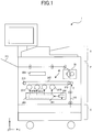
- FIG. 1 is a schematic view of the image forming apparatus according to the embodiment.
- the image forming apparatus 1 includes a reading unit R, an image forming unit P, and a paper cassette unit C.
- the reading unit R reads a document sheet placed on a platen with a CCD (charge-coupled device) image sensor, for example, so as to convert an optical signal into digital data.
- the image forming unit P acquires a document image read in the reading unit R or print data from an external personal computer, and forms and fixes a toner image on a sheet.
- CCD charge-coupled device
- the image forming unit P includes a laser scanning section 200 and photoconductor drums 201Y, 201M, 201C, and 201K.
- the laser scanning section 200 includes a polygon mirror 208 and an optical system 241. On the basis of image signals for colors of yellow (Y), magenta (M), cyan (C), and black (K), the laser scanning section 200 irradiates the photoconductor drums 201Y to 201K to provide an image to be formed on the sheet.
- the photoconductor drums 201Y to 201K retain respective color toners supplied from a developing device (not shown) according to the above-described irradiated locations.
- the photoconductor drums 201Y to 201K sequentially transfer the retained toner images onto a transfer belt 207.
- the transfer belt 207 is an endless belt.
- the transfer belt 207 conveys the toner image to a transfer location T by the rotary driving of rollers 213.
- a conveyance path 101 conveys a sheet stocked in the paper cassette unit C through the transfer location T, a fixing device 30, and an output tray 211 in this order.
- the sheet stocked in the paper cassette unit C is conveyed to the transfer location T while being guided by the conveyance path 101.
- the transfer belt 207 then transfers the toner image onto the sheet at the transfer location T.
- the sheet having the toner image formed on a surface thereof is conveyed to the fixing device 30 while being guided by the conveyance path 101.
- the fixing device 30 causes the toner image to penetrate into the sheet and fix therein by the heating and fusion of the toner image. This can prevent the toner image on the sheet from being disturbed by an external force.
- the conveyance path 101 conveys the sheet having the fixed toner image to the output tray 211 and ejects the sheet from the image forming apparatus 1.
- a controller 801 is a unit for controlling devices and mechanisms in the image forming apparatus 1 in a centralized manner.
- the controller 801 includes, for example, a central processor such as a central processing unit (CPU), and volatile and non-volatile memories.
- a central processor controls the devices and the mechanisms in the image forming apparatus 1 by executing programs stored in memories.
- the controller 801 may implement part of the functions as a circuit.
- a configuration including the sections used for conveying an image (toner image) to be formed to the transfer location T and transferring the image onto the sheet is referred to as a transfer unit 40.
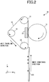
- FIG. 2 is a diagram illustrating a configuration example of the fixing device 30 (heating device).
- the fixing device 30 includes a plate-shaped heater 32, and an endless belt 34 suspended by a plurality of rollers.
- the fixing device 30 also includes driving rollers 33 for suspending the endless belt 34 and rotary-driving the endless belt 34 in a given direction.
- the fixing device 30 also includes a tension roller 35 for providing tension as well as suspending the endless belt 34.
- the fixing device 30 also includes a pressure roller 31 (pressure member) having an elastic layer formed on a surface thereof. A heat generating side of the heater 32 is in contact with an inner surface of the endless belt 34. The heater 32 is pressed against the pressure roller 31.
- the endless belt 34 interposes and conveys the sheet together with the pressure roller 31, heats the sheet, and thereby fixes the image on the sheet onto the sheet.
- the heater 32 faces the pressure roller 31 via the endless belt 34, and heats the endless belt 34.
- a heat generating resistive layer (a heat generating resistive member 60 to be described later) is stacked on a ceramic substrate, and a protective layer made of a heat-resistant material is further stacked thereon.
- the protective layer is provided in order to prevent the ceramic substrate and the heat generating resistive layer from being in contact with the endless belt 34. This can reduce the abrasion of the endless belt 34.
- the ceramic substrate of the heater 32 has a thickness of 1 to 2 mm.
- the protective layer is made of SiO 2 and has a thickness of 60 to 80 ⁇ m.
- the endless belt 34 includes a base layer (Ni/SUS/PI: a thickness of 60 to 100 ⁇ m), an elastic layer (Si rubber: a thickness of 100 to 300 ⁇ m), and a release layer (PFA: a thickness of 15 to 50 ⁇ m) sequentially provided from the side in contact with the heater 32.
- the thicknesses and materials of such layers are provided by way of example only.
- the endless belt 34 may utilize the rotation of the pressure roller 31 as its source of motive power.
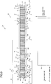
- FIG. 3 illustrates a heat generating mechanism 50.
- a direction corresponding to a sheet conveyance direction as well as a shorter-side direction of (the ceramic substrate of) the heater 32 is defined as a Z-axis direction (second direction).
- a direction corresponding to a sheet width direction as well as a longer-side direction of the heater 32 is defined as a Y-axis direction (first direction).
- the Y-axis direction is perpendicular to the Z-axis direction.
- a direction corresponding to a direction toward the pressure roller 31 as well as a vertical direction of the heater 32 is defined as an X-axis direction.
- the X-axis direction is perpendicular to the Z-axis direction and the Y-axis direction.
- the heater 32 includes the heat generating mechanism 50 for causing the heat generation of the heater 32.
- the heat generating mechanism 50 includes resistive members 61 and 62, a plurality of electrodes 601 to 607, and an electrode 610.
- the heat generating mechanism 50 also includes a plurality of switching elements 701 to 707, a power source 65, and wiring 66.
- the plurality of switching elements 701 to 707 are referred to as a switch unit 700.
- the resistive members 61 and 62 face a surface of the sheet 105 being conveyed.
- the plurality of resistive members 61 and 62 are arranged in the Y-axis direction.
- the Y-axis direction is perpendicular to the sheet conveyance direction.
- Each of the resistive members 61 and 62 is connected to the electrode 610 (second pole-side electrode) at one end thereof and connected to any one of the electrodes 601 to 607 (first pole-side electrode) at the other end thereof.
- the electrode 610 and the electrodes 601 to 607 are each made of an aluminum layer. While the electrode 610, which is one of the electrodes, is integrally formed, the other one of the electrodes is divided into the electrodes 601 to 607 as shown in the figure. Such divisions of the electrodes 601 to 607 are herein referred to as blocks (blocks 71 to 77).
- the resistive members 61 are disposed at both ends of each of the blocks 71 to 77, and the resistive members 62 are disposed on the inner side of such a block.
- a length (width) of the resistive member 61 in the Y-axis direction is set larger than a length (width) of the resistive member 62 in the Y-axis direction. An area of the resistive member 61 is thus larger than an area of the resistive member 62. The reason for this will be described later.
- the electrodes 601 to 607 are connected to the switching elements 701 to 707, respectively.
- the resistive members 61 and 62 in the block are energized by the power source 65 to generate heat for each of the blocks 71 to 77.
- the positions of the blocks 71 to 77 and the lengths thereof in the Y-axis direction are determined on the basis of the standard sizes of sheets.
- the sheet 105 being conveyed has a small size, heat generation in a region where no sheet passes through is essentially unneeded. Therefore, in this embodiment, ON and OFF control is performed for each of the blocks 71 to 77 according to the size of a sheet being conveyed.
- the block 74 is turned ON and the other blocks are turned OFF.
- the blocks 73, 74, and 75 are turned ON and the other blocks 71, 72, 76, and 77 are turned OFF, for example.
- the electrodes 601 to 607 are connected to one of the poles in the power source 65.
- the electrodes 601 to 607 are connected to one ends 611 and 621 of the resistive members 61 and 62 in the Z-axis direction.
- the electrodes 601 to 607 divide the plurality of resistive members 61 and 62 into the plurality of blocks 71 to 77.
- the electrodes 601 to 607 cause the plurality of resistive members 61 and 62 to generate heat by the block.
- the electrodes 601 to 607 are first pole-side first electrodes provided in the blocks 71 to 77 (first blocks) each including the plurality of resistive members 61 and 62 arranged successively in the Y-axis direction.
- the electrodes 601 to 607, which are the first pole-side first electrodes, extend across the one ends 611 and 621 of the resistive members 61 and 62 in the blocks 71 to 77 (first blocks).
- the electrodes 601 to 607 connect to the one ends 611 and 621.
- the electrode 610 is the second pole-side electrode extending across the other ends 612 and 622 of the resistive members 61 and 62 in the plurality of blocks 71 to 77 (all blocks) arranged successively in the Y-axis direction.
- the electrode 610 which is the second pole-side electrode, connects to the other ends 612 and 622 as well as to the other one of the poles in the power source 65.
- a length L10 of the block 74 in the Y-axis direction is greater than lengths L20 and L30 of the other blocks 71 to 73 and 75 to 77 in the Y-axis direction.
- the lengths L20 of the blocks 73 and 75 in the Y-axis direction which are disposed on the both sides of the block 74, are equal to each other.
- the lengths L30 of the blocks 72 and 76 in the Y-axis direction, which are disposed on the outer sides of the blocks 73 and 75, are equal to each other and smaller than the lengths L20 of the blocks 73 and 75.
- the lengths L30 of the blocks 71 and 77 in the Y-axis direction, which are disposed on the outer sides of the blocks 72 and 76 are equal to each other and equal to the lengths L30 of the blocks 72 and 76.
- FIG. 4 shows an enlarged view illustrating the vicinity of the blocks 71 and 72.
- the lower part of FIG. 4 provides a graph roughly showing a temperature distribution.
- the vertical axis of the temperature distribution graph represents a temperature transferred to the endless belt 34.
- the horizontal axis thereof represents a distance from an end of the heat generating resistive member 60.
- the resistive member 61 is longer than the resistive member 62 in the Y-axis direction (width direction).
- the resistive members 61 are disposed at the both ends of each block in the Y-axis direction.
- a gap L1 between the resistive members 62 in each block (or between the resistive members 61 and 62 in each block) is set within 1 mm in this embodiment.
- a temperature corresponding to the position of such a gap is lower than a temperature corresponding to the position of the resistive member as shown in the lower part of FIG. 4 .
- the gap L1 becomes larger (longer), this tendency becomes more prominent and thus a temperature difference on the temperature distribution graph becomes larger.
- the length of the gap L1 may be changed according to the size or material of the resistive member.
- a gap L2 between adjacent ones of the blocks 71 to 77 (between the resistive members 61) is set longer than the gap L1 in the blocks 71 to 77.
- the gap L2 between adjacent ones of the blocks 71 to 77 is larger than the gap L1 between the resistive members 61 and 62 in the blocks 71 to 77. This is because a certain distance or more needs to be provided between adjacent ones of the blocks 71 to 77 in order to prevent leakage therebetween.
- the length of the gap L2 is set to about 1.5 mm (in the case of 100 V). The length of the gap L2 may also be changed according to the size or material of the resistive member, or the voltage value.
- the width of the resistive members 61 positioned at the both ends of each of the blocks 71 to 77 is set longer than the width of the resistive member 62, so that the resistive member 61 reliably has an area larger than that of the resistive member 62.
- temperature in the resistive member 61 becomes higher than temperature in the resistive member 62 (shown with the solid line on the temperature distribution graph).
- the amount of heat generation in each of the resistive members 61 positioned at the both ends in the Y-axis direction is greater than the amount of heat generation in each of the other resistive members 62.
- the temperature distribution graph shown in the lower part of FIG. 4 shows actual temperature in this embodiment not with the solid line but with a broken line. This can prevent the temperature difference from becoming prominent, thereby maintaining the evenness of heating temperature.
- FIG. 5 is a graph showing temperature distributions when the in-block gap L1 is set to 0.1 mm and the inter-block gap L2 is set to 1.5 mm.
- the broken line shows a temperature distribution when the area of the resistive member 61 disposed at each end in the blocks 71 to 77 is increased by doubling the width thereof.
- the solid line shows a temperature distribution when the resistive members 61 and 62 all having the same width (the same area) are employed.
- the horizontal axis of the graph represents a distance in the Y-axis direction wherein the center of the heater 32 in the Y-axis direction is defined as the reference value zero.
- the temperature gradually increases over a range from -150 to -50 on the horizontal axis and reaches a predetermined temperature (about 150°C in this embodiment) in a central region.
- the temperature gradually decreases over a range from 50 to 150 on the horizontal axis.
- the temperature rapidly increases around a range from -150 to -130 to reach the predetermined temperature, and rapidly decreases around a range from 130 to 150 to reach a low temperature. In other words, this means that the broken-line temperature distribution has an increased range in which the predetermined temperature is achieved. This is because the increased width of the inter-block gap L2 leads to the improved efficiency in heat conduction between adjacent ones of the blocks 71 to 77.
- each block 71 to 77 includes the plurality of resistive members 61 and 62, each block may include only a single resistive member 61 or 62.
- the heat generating resistive member 60 is divided in blocks only, and each of the blocks 71 to 77 has a single body.
- An aluminum material may be used as a material of the electrodes.
- FIG. 6 is a diagram illustrating a configuration example of a fixing device 30A.
- a film guide 36 has a semi-cylindrical shape and accommodates a heater 32 in a recess 361 provided on an outer periphery thereof.
- a fixing film 34A (belt) is an endless rotating belt.
- the fixing film 34A is fitted over the outer periphery of the film guide 36.
- the fixing film 34A is interposed between the film guide 36 and a pressure roller 31 and driven by the rotation of the pressure roller 31.
- the above-described heater 32 is in contact with the fixing film 34A to heat the fixing film 34A.
- a sheet 105 having a toner image formed thereon is conveyed to a place between the fixing film 34A and the pressure roller 31.
- the fixing film 34A heats the sheet and thereby fixes the toner image on the sheet onto the sheet.
- the aspects of the heater 32 and the heat generating mechanism 50 shown in FIGs. 3 and 4 can be also applied to the fixing device 30A of the second embodiment.
- FIG. 7 is a plan view of a heater 32 illustrating a block 74B.
- At least one of the blocks 71 to 77 is a block (first block) including the plurality of resistive members 61 and 62 arranged successively in the Y-axis direction.
- the single block 74B includes only a single resistive member 63. Electrodes 601 to 603, 604B, and 605 to 607 connect to one of the poles in a power source 65 and function as a first pole-side electrode that causes a plurality of resistive members 61 to 63 to generate heat by the block.
- the electrode 604B is provided in the block 74B (second block) having the single resistive member 63.
- the electrode 604B is a first pole-side second electrode connected to one end 631 of the resistive member 63 in the Z-axis direction.
- a length of the block 74B (second block) in the Y-axis direction is larger than lengths of the other blocks 71 to 73 and 75 to 77 in the Y-axis direction.
- Other configurations of the third embodiment are similar to those of the first embodiment.
- the block 74 or 74B that is turned ON when a sheet with the smallest size is heated is disposed in the central region of the blocks 71 to 77 in the Y-axis direction.
- the block 74 or 74B that is turned ON when a sheet with the smallest size is heated may be disposed at an end of the blocks 71 to 77 in the Y-axis direction.
- a length of the block 74 or 74B in the Y-axis direction which is disposed at the end in the Y-axis direction, may be larger than lengths of the other blocks 71 to 73 and 75 to 77 in the Y-axis direction.
- the embodiments can prevent unnecessary heat generation and can reduce heating unevenness.
- the resistive members 61 and 62 divided into blocks by the electrodes 601 to 607 are energized simultaneously and all together by the block in the embodiments.
- the resistive members 61 and 62 in the same one of the blocks 71 to 77 similarly increase their temperatures. Consequently, a temperature difference among these resistive members 61 and 62 is less likely to occur in this embodiment as compared to a configuration in which the resistive members 61 and 62 are energized not by a block but on an individual basis, for example. Therefore, the occurrence of the temperature unevenness in the same one of the blocks 71 to 77 can be reduced.
- the fixing devices 30 and 30A have been described as examples of the heating device.
- the heating device may perform a decolorization treatment for decolorizing an image on a sheet by heating the sheet.
- the image is assumed to be formed with a decolorable colorant, which is decolorized when heated.
- the heating device may be employed for purposes other than the heat treatment of a sheet.
- the heating device may be employed for a treatment to uniformly heat and dry a panel, for example.
Landscapes
- Physics & Mathematics (AREA)
- General Physics & Mathematics (AREA)
- Fixing For Electrophotography (AREA)
- Control Of Resistance Heating (AREA)
Abstract
Description
- Embodiments described herein relate generally to circuit configurations of a heater.
- A fixing device in which a heater is pressed against a pressure roller via a belt has been known in the art. The belt and the pressure roller rotate together to send a sheet downstream. The heater heats the sheet via the belt. In this device, the heater includes a plurality of resistive members arranged in a direction perpendicular to a sheet conveyance direction. Electrodes are individually connected to the resistive members. The device selects resistive members to be energized according to the size of a sheet to be heated.
- Since the electrodes are individually connected to the resistive members in such a device, the heater disadvantageously has a complicated configuration.
-
-
FIG. 1 is a schematic view illustrating an image forming apparatus according to an embodiment; -
FIG. 2 is a diagram illustrating a configuration of a fixing device according to the embodiment; -
FIG. 3 is a diagram illustrating a configuration example of a heat generating mechanism in the fixing device according to the embodiment; -
FIG. 4 is an enlarged view illustrating the heat generating mechanism shown inFIG. 3 with a graph showing an exemplary temperature distribution; -
FIG. 5 is a graph showing a temperature distribution when the embodiment is applied on the basis of numeric conditions, and a temperature distribution for comparison; -
FIG. 6 is a diagram illustrating a configuration example of another fixing device; and -
FIG. 7 is a plan view of a heater. - A heater according to an embodiment generally includes resistive members and a first pole-side electrode. The plurality of resistive members are arranged in a first direction. The first pole-side electrode is connected to one ends of the resistive members in a second direction perpendicular to the first direction and configured to divide the plurality of resistive members into a plurality of blocks and to cause the plurality of resistive members to generate heat by the block. The first pole-side electrode includes a first pole-side first electrode provided in a first block including the resistive members arranged successively in the first direction, extending across the one ends of the resistive members in the first block, and connected to the one ends.
- Preferably, in the resistive members in the first block, an amount of heat generation in each of the resistive members disposed at both ends in the first direction is greater than an amount of heat generation in each of the other resistive members.
- Preferably, the heater comprises a second pole-side electrode provided across the plurality of blocks, which extends across other ends of the resistive members in the second direction in the plurality of blocks, and is connected to the other ends.
- Preferably, a gap between adjacent ones of the blocks is larger than a gap between adjacent ones of the resistive members in the first block.
- Preferably, the plurality of blocks include the first block, and a second block including only one of the resistive members, and the first pole-side electrode includes the first pole-side first electrode and a first pole-side second electrode connected to the one end of the resistive member in the second block.
- Preferably, among the plurality of blocks, a length of a block in the first direction that is disposed in a central region in the first direction is larger than lengths of the other blocks in the first direction.
- Preferably, among the plurality of blocks, a length of a block in the first direction that is disposed at an end in the first direction is larger than lengths of the other blocks in the first direction.
- Preferably, the plurality of blocks include the first block, and a second block disposed in a central region in the first direction and including only one of the resistive members, the first pole-side electrode includes the first pole-side first electrode and a first pole-side second electrode connected to the one end of the resistive member in the second block, and a length of the second block in the first direction is larger than lengths of the other blocks in the first direction.
- Preferably, the plurality of blocks include the first block and a second block disposed at an end in the first direction and including only one of the resistive members, the first pole-side electrode includes the first pole-side first electrode and a first pole-side second electrode connected to the one end of the resistive member in the second block, and a length of the second block in the first direction is larger than lengths of the other blocks in the first direction.
- A heating device according to an embodiment generally includes a pressure member, a belt, and a heater. The belt is configured to interpose and convey a sheet together with the pressure member and to heat the sheet and thereby fix an image on the sheet onto the sheet. The heater faces the pressure member via the belt and heats the belt. The heater includes: a plurality of resistive members arranged in a first direction; and a first pole-side electrode connected to one ends of the resistive members in a second direction perpendicular to the first direction and configured to divide the plurality of resistive members into a plurality of blocks and to cause the plurality of resistive members to generate heat by the block. The first pole-side electrode includes a first pole-side first electrode provided in a first block including the resistive members arranged successively in the first direction, extending across the one ends of the resistive members in the first block, and connected to the one ends.
- An image forming apparatus and a fixing device according to an embodiment will now be described below with reference to the drawings.
-
FIG. 1 is a schematic view of the image forming apparatus according to the embodiment. The image forming apparatus 1 includes a reading unit R, an image forming unit P, and a paper cassette unit C. The reading unit R reads a document sheet placed on a platen with a CCD (charge-coupled device) image sensor, for example, so as to convert an optical signal into digital data. The image forming unit P acquires a document image read in the reading unit R or print data from an external personal computer, and forms and fixes a toner image on a sheet. - The image forming unit P includes a
laser scanning section 200 andphotoconductor drums laser scanning section 200 includes apolygon mirror 208 and anoptical system 241. On the basis of image signals for colors of yellow (Y), magenta (M), cyan (C), and black (K), thelaser scanning section 200 irradiates thephotoconductor drums 201Y to 201K to provide an image to be formed on the sheet. - The
photoconductor drums 201Y to 201K retain respective color toners supplied from a developing device (not shown) according to the above-described irradiated locations. Thephotoconductor drums 201Y to 201K sequentially transfer the retained toner images onto atransfer belt 207. Thetransfer belt 207 is an endless belt. Thetransfer belt 207 conveys the toner image to a transfer location T by the rotary driving ofrollers 213. - A
conveyance path 101 conveys a sheet stocked in the paper cassette unit C through the transfer location T, afixing device 30, and anoutput tray 211 in this order. The sheet stocked in the paper cassette unit C is conveyed to the transfer location T while being guided by theconveyance path 101. Thetransfer belt 207 then transfers the toner image onto the sheet at the transfer location T. - The sheet having the toner image formed on a surface thereof is conveyed to the
fixing device 30 while being guided by theconveyance path 101. Thefixing device 30 causes the toner image to penetrate into the sheet and fix therein by the heating and fusion of the toner image. This can prevent the toner image on the sheet from being disturbed by an external force. Theconveyance path 101 conveys the sheet having the fixed toner image to theoutput tray 211 and ejects the sheet from the image forming apparatus 1. - A
controller 801 is a unit for controlling devices and mechanisms in the image forming apparatus 1 in a centralized manner. Thecontroller 801 includes, for example, a central processor such as a central processing unit (CPU), and volatile and non-volatile memories. According to an embodiment, a central processor controls the devices and the mechanisms in the image forming apparatus 1 by executing programs stored in memories. Alternatively, thecontroller 801 may implement part of the functions as a circuit. - A configuration including the sections used for conveying an image (toner image) to be formed to the transfer location T and transferring the image onto the sheet is referred to as a
transfer unit 40. -
FIG. 2 is a diagram illustrating a configuration example of the fixing device 30 (heating device). Thefixing device 30 includes a plate-shaped heater 32, and anendless belt 34 suspended by a plurality of rollers. Thefixing device 30 also includesdriving rollers 33 for suspending theendless belt 34 and rotary-driving theendless belt 34 in a given direction. Thefixing device 30 also includes atension roller 35 for providing tension as well as suspending theendless belt 34. Thefixing device 30 also includes a pressure roller 31 (pressure member) having an elastic layer formed on a surface thereof. A heat generating side of theheater 32 is in contact with an inner surface of theendless belt 34. Theheater 32 is pressed against thepressure roller 31. This allows asheet 105 having a toner image thereon to be interposed, heated, and pressurized at a contact portion (nip portion) formed by theendless belt 34 and thepressure roller 31. In other words, theendless belt 34 interposes and conveys the sheet together with thepressure roller 31, heats the sheet, and thereby fixes the image on the sheet onto the sheet. Theheater 32 faces thepressure roller 31 via theendless belt 34, and heats theendless belt 34. - In the
heater 32, a heat generating resistive layer (a heat generatingresistive member 60 to be described later) is stacked on a ceramic substrate, and a protective layer made of a heat-resistant material is further stacked thereon. The protective layer is provided in order to prevent the ceramic substrate and the heat generating resistive layer from being in contact with theendless belt 34. This can reduce the abrasion of theendless belt 34. - In this embodiment, the ceramic substrate of the
heater 32 has a thickness of 1 to 2 mm. The protective layer is made of SiO2 and has a thickness of 60 to 80 µm. Theendless belt 34 includes a base layer (Ni/SUS/PI: a thickness of 60 to 100 µm), an elastic layer (Si rubber: a thickness of 100 to 300 µm), and a release layer (PFA: a thickness of 15 to 50 µm) sequentially provided from the side in contact with theheater 32. The thicknesses and materials of such layers are provided by way of example only. - The
endless belt 34 may utilize the rotation of thepressure roller 31 as its source of motive power. -
FIG. 3 illustrates aheat generating mechanism 50. - Hereinafter, a direction corresponding to a sheet conveyance direction as well as a shorter-side direction of (the ceramic substrate of) the
heater 32 is defined as a Z-axis direction (second direction). A direction corresponding to a sheet width direction as well as a longer-side direction of theheater 32 is defined as a Y-axis direction (first direction). The Y-axis direction is perpendicular to the Z-axis direction. A direction corresponding to a direction toward thepressure roller 31 as well as a vertical direction of theheater 32 is defined as an X-axis direction. The X-axis direction is perpendicular to the Z-axis direction and the Y-axis direction. - The
heater 32 includes theheat generating mechanism 50 for causing the heat generation of theheater 32. Theheat generating mechanism 50 includesresistive members electrodes 601 to 607, and anelectrode 610. Theheat generating mechanism 50 also includes a plurality of switchingelements 701 to 707, apower source 65, andwiring 66. The plurality of switchingelements 701 to 707 are referred to as aswitch unit 700. - The
resistive members sheet 105 being conveyed. The plurality ofresistive members resistive members electrodes 601 to 607 (first pole-side electrode) at the other end thereof. - The
electrode 610 and theelectrodes 601 to 607 are each made of an aluminum layer. While theelectrode 610, which is one of the electrodes, is integrally formed, the other one of the electrodes is divided into theelectrodes 601 to 607 as shown in the figure. Such divisions of theelectrodes 601 to 607 are herein referred to as blocks (blocks 71 to 77). In this embodiment, theresistive members 61 are disposed at both ends of each of theblocks 71 to 77, and theresistive members 62 are disposed on the inner side of such a block. A length (width) of theresistive member 61 in the Y-axis direction is set larger than a length (width) of theresistive member 62 in the Y-axis direction. An area of theresistive member 61 is thus larger than an area of theresistive member 62. The reason for this will be described later. - The
electrodes 601 to 607 are connected to the switchingelements 701 to 707, respectively. By the ON and OFF operations of the switchingelements 701 to 707, theresistive members power source 65 to generate heat for each of theblocks 71 to 77. - The positions of the
blocks 71 to 77 and the lengths thereof in the Y-axis direction are determined on the basis of the standard sizes of sheets. When thesheet 105 being conveyed has a small size, heat generation in a region where no sheet passes through is essentially unneeded. Therefore, in this embodiment, ON and OFF control is performed for each of theblocks 71 to 77 according to the size of a sheet being conveyed. When an A5-size small sheet is heated, for example, theblock 74 is turned ON and the other blocks are turned OFF. In the case of an A4-size sheet, theblocks other blocks elements 701 to 707 in accordance with control made by thecontroller 801. In this manner, unnecessary heat generation can be prevented from occurring by controlling which block(s) (the resistive members therein) are energized according to the sheet size. - In this embodiment, while energization control for each of the blocks is performed independently, energization control for the
resistive members - As mentioned above, the
electrodes 601 to 607 (first pole-side electrode) are connected to one of the poles in thepower source 65. Theelectrodes 601 to 607 are connected to one ends 611 and 621 of theresistive members electrodes 601 to 607 divide the plurality ofresistive members blocks 71 to 77. Theelectrodes 601 to 607 cause the plurality ofresistive members - In this embodiment, the
electrodes 601 to 607 are first pole-side first electrodes provided in theblocks 71 to 77 (first blocks) each including the plurality ofresistive members electrodes 601 to 607, which are the first pole-side first electrodes, extend across the one ends 611 and 621 of theresistive members blocks 71 to 77 (first blocks). Theelectrodes 601 to 607 connect to the one ends 611 and 621. - The
electrode 610, on the other hand, is the second pole-side electrode extending across the other ends 612 and 622 of theresistive members blocks 71 to 77 (all blocks) arranged successively in the Y-axis direction. Theelectrode 610, which is the second pole-side electrode, connects to the other ends 612 and 622 as well as to the other one of the poles in thepower source 65. - Among the plurality of
blocks 71 to 77, a length L10 of theblock 74 in the Y-axis direction, which is disposed in a central region in the Y-axis direction, is greater than lengths L20 and L30 of theother blocks 71 to 73 and 75 to 77 in the Y-axis direction. The lengths L20 of theblocks block 74, are equal to each other. The lengths L30 of theblocks blocks blocks blocks blocks blocks - The upper part of
FIG. 4 shows an enlarged view illustrating the vicinity of theblocks FIG. 4 provides a graph roughly showing a temperature distribution. The vertical axis of the temperature distribution graph represents a temperature transferred to theendless belt 34. The horizontal axis thereof represents a distance from an end of the heat generatingresistive member 60. - As shown in the upper part of
FIG. 4 andFIG. 3 described above, theresistive member 61 is longer than theresistive member 62 in the Y-axis direction (width direction). In addition, theresistive members 61 are disposed at the both ends of each block in the Y-axis direction. A gap L1 between theresistive members 62 in each block (or between theresistive members FIG. 4 . As the gap L1 becomes larger (longer), this tendency becomes more prominent and thus a temperature difference on the temperature distribution graph becomes larger. By setting the length of the gap L1 within 1 mm as in this embodiment, heating unevenness can be reduced to an acceptable level. Note that the length of the gap L1 may be changed according to the size or material of the resistive member. - In this embodiment, a gap L2 between adjacent ones of the
blocks 71 to 77 (between the resistive members 61) is set longer than the gap L1 in theblocks 71 to 77. In other words, the gap L2 between adjacent ones of theblocks 71 to 77 is larger than the gap L1 between theresistive members blocks 71 to 77. This is because a certain distance or more needs to be provided between adjacent ones of theblocks 71 to 77 in order to prevent leakage therebetween. In this embodiment, the length of the gap L2 is set to about 1.5 mm (in the case of 100 V). The length of the gap L2 may also be changed according to the size or material of the resistive member, or the voltage value. - Since the gap L2 has a longer length as described above, a temperature corresponding to the position of the inter-block gap L2 (gap length = L2) is even lower than a temperature corresponding to the position of the in-block gap L1 (gap length = L1) as shown in the lower part of
FIG. 4 (shown with the solid line on the temperature distribution graph). In order to reduce such a temperature decrease, the width of theresistive members 61 positioned at the both ends of each of theblocks 71 to 77 is set longer than the width of theresistive member 62, so that theresistive member 61 reliably has an area larger than that of theresistive member 62. Due to such a larger area, temperature in theresistive member 61 becomes higher than temperature in the resistive member 62 (shown with the solid line on the temperature distribution graph). In other words, in theresistive members blocks 71 to 77, the amount of heat generation in each of theresistive members 61 positioned at the both ends in the Y-axis direction is greater than the amount of heat generation in each of the otherresistive members 62. - While the amount of heat generation in the
resistive member 61 is increased as mentioned above, the heat generated in theresistive member 61 transfers from the high-temperature side to the low-temperature side due to heat conduction. In other words, the heat transfers to the position of the inter-block gap L2 (gap length = L2) adjacent to theresistive members 61. Consequently, the temperature in theresistive member 61 is decreased, whereas the temperature in the inter-block gap L2 is increased. The temperature distribution graph shown in the lower part ofFIG. 4 shows actual temperature in this embodiment not with the solid line but with a broken line. This can prevent the temperature difference from becoming prominent, thereby maintaining the evenness of heating temperature. -
FIG. 5 is a graph showing temperature distributions when the in-block gap L1 is set to 0.1 mm and the inter-block gap L2 is set to 1.5 mm. The broken line shows a temperature distribution when the area of theresistive member 61 disposed at each end in theblocks 71 to 77 is increased by doubling the width thereof. The solid line, on the other hand, shows a temperature distribution when theresistive members heater 32 in the Y-axis direction is defined as the reference value zero. - As shown in
FIG. 5 , in the solid-line temperature distribution, the temperature gradually increases over a range from -150 to -50 on the horizontal axis and reaches a predetermined temperature (about 150°C in this embodiment) in a central region. The temperature gradually decreases over a range from 50 to 150 on the horizontal axis. In the broken-line temperature distribution, on the other hand, the temperature rapidly increases around a range from -150 to -130 to reach the predetermined temperature, and rapidly decreases around a range from 130 to 150 to reach a low temperature. In other words, this means that the broken-line temperature distribution has an increased range in which the predetermined temperature is achieved. This is because the increased width of the inter-block gap L2 leads to the improved efficiency in heat conduction between adjacent ones of theblocks 71 to 77. - While each of the above-described
blocks 71 to 77 includes the plurality ofresistive members resistive member resistive member 60 is divided in blocks only, and each of theblocks 71 to 77 has a single body. - An aluminum material may be used as a material of the electrodes.
- The second embodiment describes an exemplary aspect in which the configuration of the fixing device in the first embodiment is modified.
FIG. 6 is a diagram illustrating a configuration example of afixing device 30A. - A
film guide 36 has a semi-cylindrical shape and accommodates aheater 32 in a recess 361 provided on an outer periphery thereof. - A fixing
film 34A (belt) is an endless rotating belt. The fixingfilm 34A is fitted over the outer periphery of thefilm guide 36. The fixingfilm 34A is interposed between thefilm guide 36 and apressure roller 31 and driven by the rotation of thepressure roller 31. - The above-described
heater 32 is in contact with the fixingfilm 34A to heat the fixingfilm 34A. - A
sheet 105 having a toner image formed thereon is conveyed to a place between the fixingfilm 34A and thepressure roller 31. The fixingfilm 34A heats the sheet and thereby fixes the toner image on the sheet onto the sheet. - The aspects of the
heater 32 and theheat generating mechanism 50 shown inFIGs. 3 and4 can be also applied to thefixing device 30A of the second embodiment. -
FIG. 7 is a plan view of aheater 32 illustrating ablock 74B. - In the first to third embodiments, it is only necessary that at least one of the
blocks 71 to 77 is a block (first block) including the plurality ofresistive members - In the third embodiment, the
single block 74B includes only a singleresistive member 63.Electrodes 601 to 603, 604B, and 605 to 607 connect to one of the poles in apower source 65 and function as a first pole-side electrode that causes a plurality ofresistive members 61 to 63 to generate heat by the block. Theelectrode 604B is provided in theblock 74B (second block) having the singleresistive member 63. Theelectrode 604B is a first pole-side second electrode connected to oneend 631 of theresistive member 63 in the Z-axis direction. A length of theblock 74B (second block) in the Y-axis direction is larger than lengths of theother blocks 71 to 73 and 75 to 77 in the Y-axis direction. Other configurations of the third embodiment are similar to those of the first embodiment. - In the first to third embodiments, the
block blocks 71 to 77 in the Y-axis direction. However, theblock blocks 71 to 77 in the Y-axis direction. In this case, among the plurality ofblocks 71 to 77, a length of theblock other blocks 71 to 73 and 75 to 77 in the Y-axis direction. - As described above, the embodiments can prevent unnecessary heat generation and can reduce heating unevenness. Moreover, the
resistive members electrodes 601 to 607 (first pole-side first electrodes) are energized simultaneously and all together by the block in the embodiments. Thus, theresistive members blocks 71 to 77 similarly increase their temperatures. Consequently, a temperature difference among theseresistive members resistive members blocks 71 to 77 can be reduced. - In the above-described embodiments, the fixing
devices - While certain embodiments have been described, these embodiments have been presented by way of example only, and are not intended to limit the scope of invention. Indeed, the novel apparatus, methods and system described herein may be embodied in a variety of other forms; furthermore, various omissions, substitutions and changes in the form of the apparatus, methods and system described herein may be made without departing from the framework of the inventions. The accompanying claims and their equivalents are intended to cover such forms or modifications as would fall within the scope of the inventions.
Claims (10)
- A heater comprising:a plurality of resistive members arranged in a first direction; anda first pole-side electrode connected to one ends of the resistive members in a second direction perpendicular to the first direction and configured to divide the plurality of resistive members into a plurality of blocks and to cause the plurality of resistive members to generate heat by the block, the first pole-side electrode including a first pole-side first electrode provided in a first block including some of the resistive members arranged successively in the first direction, extending across the one ends of the resistive members in the first block, and connected to the one ends.
- The heater according to claim 1, wherein in the resistive members in the first block, an amount of heat generation in each of the resistive members disposed at both ends in the first direction is greater than an amount of heat generation in each of the other resistive members.
- The heater according to claim 1 or 2, further comprising a second pole-side electrode provided across the plurality of blocks, which extends across other ends of the resistive members in the second direction in the plurality of blocks, and is connected to the other ends.
- The heater according to any one of claims 1 to 3, wherein a gap between adjacent ones of the blocks is larger than a gap between adjacent ones of the resistive members in the first block.
- The heater according to any one of claims 1 to 4, wherein
the plurality of blocks include the first block, and a second block including only one of the resistive members, and
the first pole-side electrode includes the first pole-side first electrode and a first pole-side second electrode connected to the one end of the resistive member in the second block. - The heater according to any one of claims 1 to 5, wherein among the plurality of blocks, a length of a block in the first direction that is disposed in a central region in the first direction is larger than lengths of the other blocks in the first direction.
- The heater according to any one of claims 1 to 5, wherein among the plurality of blocks, a length of a block in the first direction that is disposed at an end in the first direction is larger than lengths of the other blocks in the first direction.
- The heater according to any one of claims 1 to 4, wherein
the plurality of blocks include the first block, and a second block disposed in a central region in the first direction and including only one of the resistive members,
the first pole-side electrode includes the first pole-side first electrode and a first pole-side second electrode connected to the one end of the resistive member in the second block, and
a length of the second block in the first direction is larger than lengths of the other blocks in the first direction. - The heater according to any one of claims 1 to 4, wherein
the plurality of blocks include the first block and a second block disposed at an end in the first direction and including only one of the resistive members,
the first pole-side electrode includes the first pole-side first electrode and a first pole-side second electrode connected to the one end of the resistive member in the second block, and
a length of the second block in the first direction is larger than lengths of the other blocks in the first direction. - A heating device comprising:a pressure member;a belt configured to interpose and convey a sheet together with the pressure member and to heat the sheet and thereby fix an image on the sheet onto the sheet; andthe heater according to claim 1 and disposed to face the pressure member via the belt and configured to heat the belt.
Priority Applications (1)
| Application Number | Priority Date | Filing Date | Title |
|---|---|---|---|
| EP19171681.0A EP3567434B1 (en) | 2016-06-20 | 2017-06-16 | Heater and heating device for dividing resistive members into blocks and causing resisitive members to generate heat by block |
Applications Claiming Priority (2)
| Application Number | Priority Date | Filing Date | Title |
|---|---|---|---|
| JP2016121403 | 2016-06-20 | ||
| JP2017097322A JP6884032B2 (en) | 2016-06-20 | 2017-05-16 | Heater, heating device |
Related Child Applications (2)
| Application Number | Title | Priority Date | Filing Date |
|---|---|---|---|
| EP19171681.0A Division EP3567434B1 (en) | 2016-06-20 | 2017-06-16 | Heater and heating device for dividing resistive members into blocks and causing resisitive members to generate heat by block |
| EP19171681.0A Division-Into EP3567434B1 (en) | 2016-06-20 | 2017-06-16 | Heater and heating device for dividing resistive members into blocks and causing resisitive members to generate heat by block |
Publications (2)
| Publication Number | Publication Date |
|---|---|
| EP3260929A1 true EP3260929A1 (en) | 2017-12-27 |
| EP3260929B1 EP3260929B1 (en) | 2019-06-05 |
Family
ID=59077886
Family Applications (2)
| Application Number | Title | Priority Date | Filing Date |
|---|---|---|---|
| EP17176319.6A Active EP3260929B1 (en) | 2016-06-20 | 2017-06-16 | Heater and heating device for dividing resistive members into block and causing resisitive members to generate heat by block |
| EP19171681.0A Active EP3567434B1 (en) | 2016-06-20 | 2017-06-16 | Heater and heating device for dividing resistive members into blocks and causing resisitive members to generate heat by block |
Family Applications After (1)
| Application Number | Title | Priority Date | Filing Date |
|---|---|---|---|
| EP19171681.0A Active EP3567434B1 (en) | 2016-06-20 | 2017-06-16 | Heater and heating device for dividing resistive members into blocks and causing resisitive members to generate heat by block |
Country Status (3)
| Country | Link |
|---|---|
| US (2) | US20170364001A1 (en) |
| EP (2) | EP3260929B1 (en) |
| CN (1) | CN107526274A (en) |
Cited By (1)
| Publication number | Priority date | Publication date | Assignee | Title |
|---|---|---|---|---|
| EP3486727B1 (en) * | 2017-10-20 | 2024-07-24 | Kabushiki Kaisha Toshiba | Fixing device and image forming apparatus |
Families Citing this family (7)
| Publication number | Priority date | Publication date | Assignee | Title |
|---|---|---|---|---|
| CN109901368B (en) * | 2014-03-19 | 2024-10-22 | 佳能株式会社 | Image heating apparatus and heater used therein |
| JP7189793B2 (en) | 2019-02-08 | 2022-12-14 | 東芝テック株式会社 | heating device |
| JP7232659B2 (en) | 2019-02-08 | 2023-03-03 | 東芝テック株式会社 | Heating device and image processing device |
| JP7337550B2 (en) * | 2019-05-27 | 2023-09-04 | キヤノン株式会社 | Image heating device and image forming device |
| US11163264B2 (en) | 2019-08-08 | 2021-11-02 | Ricoh Company, Ltd. | Image forming apparatus |
| US11143991B2 (en) * | 2019-08-08 | 2021-10-12 | Ricoh Company, Ltd. | Image forming apparatus including a cooler and a heater |
| JP2025075126A (en) | 2023-10-31 | 2025-05-15 | 京セラドキュメントソリューションズ株式会社 | Image forming device |
Citations (4)
| Publication number | Priority date | Publication date | Assignee | Title |
|---|---|---|---|---|
| US20090263171A1 (en) * | 2008-04-18 | 2009-10-22 | Hiroyuki Kageyama | Planar heat generating element, fixing device including the same, and image forming apparatus including the same |
| EP2711778A2 (en) * | 2012-09-19 | 2014-03-26 | Canon Kabushiki Kaisha | Heater and image heating device mounted with heater |
| US20150331373A1 (en) * | 2014-05-19 | 2015-11-19 | Toshiba Tec Kabushiki Kaisha | Fixing device and fixing temperature control method of fixing device |
| EP3001253A1 (en) * | 2014-09-24 | 2016-03-30 | Toshiba TEC Kabushiki Kaisha | Fixing device and image forming apparatus |
Family Cites Families (5)
| Publication number | Priority date | Publication date | Assignee | Title |
|---|---|---|---|---|
| JPH0529067A (en) * | 1991-07-25 | 1993-02-05 | Rohm Co Ltd | Structure of heating element and heating device for office automation equipment |
| US5376773A (en) * | 1991-12-26 | 1994-12-27 | Canon Kabushiki Kaisha | Heater having heat generating resistors |
| JP5648263B2 (en) * | 2008-05-30 | 2015-01-07 | 株式会社リコー | Image forming apparatus |
| JP2016018181A (en) * | 2014-07-11 | 2016-02-01 | 富士ゼロックス株式会社 | Heating device, fixing device and image forming apparatus |
| JP2016145909A (en) * | 2015-02-06 | 2016-08-12 | キヤノン株式会社 | Fixing device and heater used in fixing device |
-
2017
- 2017-06-15 US US15/624,600 patent/US20170364001A1/en not_active Abandoned
- 2017-06-16 EP EP17176319.6A patent/EP3260929B1/en active Active
- 2017-06-16 CN CN201710461536.7A patent/CN107526274A/en active Pending
- 2017-06-16 EP EP19171681.0A patent/EP3567434B1/en active Active
-
2020
- 2020-04-22 US US16/855,300 patent/US20200249606A1/en not_active Abandoned
Patent Citations (4)
| Publication number | Priority date | Publication date | Assignee | Title |
|---|---|---|---|---|
| US20090263171A1 (en) * | 2008-04-18 | 2009-10-22 | Hiroyuki Kageyama | Planar heat generating element, fixing device including the same, and image forming apparatus including the same |
| EP2711778A2 (en) * | 2012-09-19 | 2014-03-26 | Canon Kabushiki Kaisha | Heater and image heating device mounted with heater |
| US20150331373A1 (en) * | 2014-05-19 | 2015-11-19 | Toshiba Tec Kabushiki Kaisha | Fixing device and fixing temperature control method of fixing device |
| EP3001253A1 (en) * | 2014-09-24 | 2016-03-30 | Toshiba TEC Kabushiki Kaisha | Fixing device and image forming apparatus |
Cited By (1)
| Publication number | Priority date | Publication date | Assignee | Title |
|---|---|---|---|---|
| EP3486727B1 (en) * | 2017-10-20 | 2024-07-24 | Kabushiki Kaisha Toshiba | Fixing device and image forming apparatus |
Also Published As
| Publication number | Publication date |
|---|---|
| EP3567434A1 (en) | 2019-11-13 |
| US20200249606A1 (en) | 2020-08-06 |
| EP3567434B1 (en) | 2022-12-07 |
| CN107526274A (en) | 2017-12-29 |
| EP3260929B1 (en) | 2019-06-05 |
| US20170364001A1 (en) | 2017-12-21 |
Similar Documents
| Publication | Publication Date | Title |
|---|---|---|
| EP3260929B1 (en) | Heater and heating device for dividing resistive members into block and causing resisitive members to generate heat by block | |
| JP7259118B2 (en) | Heating device, image forming device | |
| US11675294B2 (en) | Heating device and image forming apparatus | |
| JP6884032B2 (en) | Heater, heating device | |
| US12306563B2 (en) | Fixing device with a heater holder having a retraction portion | |
| CN107526267B (en) | Fixing device and method for adjusting gap width thereof, and image forming device | |
| KR20210028692A (en) | Phase heating device and image forming device | |
| JP7161011B2 (en) | image forming device | |
| US20200236742A1 (en) | Heater and heating device | |
| CN110119076A (en) | Image forming apparatus | |
| JP2007240606A (en) | Image heating apparatus and heating body used in the apparatus | |
| US10444679B2 (en) | Image forming apparatus which can form an image on a label sheet and control method thereof | |
| EP3260930B1 (en) | Heater, fixing device, and image forming apparatus | |
| JP6982402B2 (en) | Heater, heating device | |
| JP2019020482A (en) | Fixing apparatus and image forming apparatus |
Legal Events
| Date | Code | Title | Description |
|---|---|---|---|
| PUAI | Public reference made under article 153(3) epc to a published international application that has entered the european phase |
Free format text: ORIGINAL CODE: 0009012 |
|
| STAA | Information on the status of an ep patent application or granted ep patent |
Free format text: STATUS: THE APPLICATION HAS BEEN PUBLISHED |
|
| AK | Designated contracting states |
Kind code of ref document: A1 Designated state(s): AL AT BE BG CH CY CZ DE DK EE ES FI FR GB GR HR HU IE IS IT LI LT LU LV MC MK MT NL NO PL PT RO RS SE SI SK SM TR |
|
| AX | Request for extension of the european patent |
Extension state: BA ME |
|
| STAA | Information on the status of an ep patent application or granted ep patent |
Free format text: STATUS: REQUEST FOR EXAMINATION WAS MADE |
|
| 17P | Request for examination filed |
Effective date: 20180627 |
|
| RBV | Designated contracting states (corrected) |
Designated state(s): AL AT BE BG CH CY CZ DE DK EE ES FI FR GB GR HR HU IE IS IT LI LT LU LV MC MK MT NL NO PL PT RO RS SE SI SK SM TR |
|
| GRAP | Despatch of communication of intention to grant a patent |
Free format text: ORIGINAL CODE: EPIDOSNIGR1 |
|
| STAA | Information on the status of an ep patent application or granted ep patent |
Free format text: STATUS: GRANT OF PATENT IS INTENDED |
|
| INTG | Intention to grant announced |
Effective date: 20181220 |
|
| GRAS | Grant fee paid |
Free format text: ORIGINAL CODE: EPIDOSNIGR3 |
|
| GRAA | (expected) grant |
Free format text: ORIGINAL CODE: 0009210 |
|
| STAA | Information on the status of an ep patent application or granted ep patent |
Free format text: STATUS: THE PATENT HAS BEEN GRANTED |
|
| AK | Designated contracting states |
Kind code of ref document: B1 Designated state(s): AL AT BE BG CH CY CZ DE DK EE ES FI FR GB GR HR HU IE IS IT LI LT LU LV MC MK MT NL NO PL PT RO RS SE SI SK SM TR |
|
| REG | Reference to a national code |
Ref country code: GB Ref legal event code: FG4D |
|
| REG | Reference to a national code |
Ref country code: CH Ref legal event code: EP |
|
| REG | Reference to a national code |
Ref country code: AT Ref legal event code: REF Ref document number: 1140613 Country of ref document: AT Kind code of ref document: T Effective date: 20190615 |
|
| REG | Reference to a national code |
Ref country code: IE Ref legal event code: FG4D |
|
| REG | Reference to a national code |
Ref country code: DE Ref legal event code: R096 Ref document number: 602017004288 Country of ref document: DE |
|
| REG | Reference to a national code |
Ref country code: NL Ref legal event code: MP Effective date: 20190605 |
|
| REG | Reference to a national code |
Ref country code: LT Ref legal event code: MG4D |
|
| PG25 | Lapsed in a contracting state [announced via postgrant information from national office to epo] |
Ref country code: AL Free format text: LAPSE BECAUSE OF FAILURE TO SUBMIT A TRANSLATION OF THE DESCRIPTION OR TO PAY THE FEE WITHIN THE PRESCRIBED TIME-LIMIT Effective date: 20190605 Ref country code: ES Free format text: LAPSE BECAUSE OF FAILURE TO SUBMIT A TRANSLATION OF THE DESCRIPTION OR TO PAY THE FEE WITHIN THE PRESCRIBED TIME-LIMIT Effective date: 20190605 Ref country code: NO Free format text: LAPSE BECAUSE OF FAILURE TO SUBMIT A TRANSLATION OF THE DESCRIPTION OR TO PAY THE FEE WITHIN THE PRESCRIBED TIME-LIMIT Effective date: 20190905 Ref country code: LT Free format text: LAPSE BECAUSE OF FAILURE TO SUBMIT A TRANSLATION OF THE DESCRIPTION OR TO PAY THE FEE WITHIN THE PRESCRIBED TIME-LIMIT Effective date: 20190605 Ref country code: FI Free format text: LAPSE BECAUSE OF FAILURE TO SUBMIT A TRANSLATION OF THE DESCRIPTION OR TO PAY THE FEE WITHIN THE PRESCRIBED TIME-LIMIT Effective date: 20190605 Ref country code: SE Free format text: LAPSE BECAUSE OF FAILURE TO SUBMIT A TRANSLATION OF THE DESCRIPTION OR TO PAY THE FEE WITHIN THE PRESCRIBED TIME-LIMIT Effective date: 20190605 Ref country code: HR Free format text: LAPSE BECAUSE OF FAILURE TO SUBMIT A TRANSLATION OF THE DESCRIPTION OR TO PAY THE FEE WITHIN THE PRESCRIBED TIME-LIMIT Effective date: 20190605 |
|
| PG25 | Lapsed in a contracting state [announced via postgrant information from national office to epo] |
Ref country code: RS Free format text: LAPSE BECAUSE OF FAILURE TO SUBMIT A TRANSLATION OF THE DESCRIPTION OR TO PAY THE FEE WITHIN THE PRESCRIBED TIME-LIMIT Effective date: 20190605 Ref country code: LV Free format text: LAPSE BECAUSE OF FAILURE TO SUBMIT A TRANSLATION OF THE DESCRIPTION OR TO PAY THE FEE WITHIN THE PRESCRIBED TIME-LIMIT Effective date: 20190605 Ref country code: GR Free format text: LAPSE BECAUSE OF FAILURE TO SUBMIT A TRANSLATION OF THE DESCRIPTION OR TO PAY THE FEE WITHIN THE PRESCRIBED TIME-LIMIT Effective date: 20190906 Ref country code: BG Free format text: LAPSE BECAUSE OF FAILURE TO SUBMIT A TRANSLATION OF THE DESCRIPTION OR TO PAY THE FEE WITHIN THE PRESCRIBED TIME-LIMIT Effective date: 20190905 |
|
| REG | Reference to a national code |
Ref country code: AT Ref legal event code: MK05 Ref document number: 1140613 Country of ref document: AT Kind code of ref document: T Effective date: 20190605 |
|
| PG25 | Lapsed in a contracting state [announced via postgrant information from national office to epo] |
Ref country code: AT Free format text: LAPSE BECAUSE OF FAILURE TO SUBMIT A TRANSLATION OF THE DESCRIPTION OR TO PAY THE FEE WITHIN THE PRESCRIBED TIME-LIMIT Effective date: 20190605 Ref country code: PT Free format text: LAPSE BECAUSE OF FAILURE TO SUBMIT A TRANSLATION OF THE DESCRIPTION OR TO PAY THE FEE WITHIN THE PRESCRIBED TIME-LIMIT Effective date: 20191007 Ref country code: RO Free format text: LAPSE BECAUSE OF FAILURE TO SUBMIT A TRANSLATION OF THE DESCRIPTION OR TO PAY THE FEE WITHIN THE PRESCRIBED TIME-LIMIT Effective date: 20190605 Ref country code: CZ Free format text: LAPSE BECAUSE OF FAILURE TO SUBMIT A TRANSLATION OF THE DESCRIPTION OR TO PAY THE FEE WITHIN THE PRESCRIBED TIME-LIMIT Effective date: 20190605 Ref country code: NL Free format text: LAPSE BECAUSE OF FAILURE TO SUBMIT A TRANSLATION OF THE DESCRIPTION OR TO PAY THE FEE WITHIN THE PRESCRIBED TIME-LIMIT Effective date: 20190605 Ref country code: SK Free format text: LAPSE BECAUSE OF FAILURE TO SUBMIT A TRANSLATION OF THE DESCRIPTION OR TO PAY THE FEE WITHIN THE PRESCRIBED TIME-LIMIT Effective date: 20190605 Ref country code: EE Free format text: LAPSE BECAUSE OF FAILURE TO SUBMIT A TRANSLATION OF THE DESCRIPTION OR TO PAY THE FEE WITHIN THE PRESCRIBED TIME-LIMIT Effective date: 20190605 |
|
| PG25 | Lapsed in a contracting state [announced via postgrant information from national office to epo] |
Ref country code: IS Free format text: LAPSE BECAUSE OF FAILURE TO SUBMIT A TRANSLATION OF THE DESCRIPTION OR TO PAY THE FEE WITHIN THE PRESCRIBED TIME-LIMIT Effective date: 20191005 Ref country code: IT Free format text: LAPSE BECAUSE OF FAILURE TO SUBMIT A TRANSLATION OF THE DESCRIPTION OR TO PAY THE FEE WITHIN THE PRESCRIBED TIME-LIMIT Effective date: 20190605 Ref country code: SM Free format text: LAPSE BECAUSE OF FAILURE TO SUBMIT A TRANSLATION OF THE DESCRIPTION OR TO PAY THE FEE WITHIN THE PRESCRIBED TIME-LIMIT Effective date: 20190605 |
|
| REG | Reference to a national code |
Ref country code: DE Ref legal event code: R097 Ref document number: 602017004288 Country of ref document: DE |
|
| REG | Reference to a national code |
Ref country code: BE Ref legal event code: MM Effective date: 20190630 |
|
| PG25 | Lapsed in a contracting state [announced via postgrant information from national office to epo] |
Ref country code: TR Free format text: LAPSE BECAUSE OF FAILURE TO SUBMIT A TRANSLATION OF THE DESCRIPTION OR TO PAY THE FEE WITHIN THE PRESCRIBED TIME-LIMIT Effective date: 20190605 Ref country code: MC Free format text: LAPSE BECAUSE OF FAILURE TO SUBMIT A TRANSLATION OF THE DESCRIPTION OR TO PAY THE FEE WITHIN THE PRESCRIBED TIME-LIMIT Effective date: 20190605 |
|
| PLBE | No opposition filed within time limit |
Free format text: ORIGINAL CODE: 0009261 |
|
| STAA | Information on the status of an ep patent application or granted ep patent |
Free format text: STATUS: NO OPPOSITION FILED WITHIN TIME LIMIT |
|
| PG25 | Lapsed in a contracting state [announced via postgrant information from national office to epo] |
Ref country code: DK Free format text: LAPSE BECAUSE OF FAILURE TO SUBMIT A TRANSLATION OF THE DESCRIPTION OR TO PAY THE FEE WITHIN THE PRESCRIBED TIME-LIMIT Effective date: 20190605 Ref country code: IE Free format text: LAPSE BECAUSE OF NON-PAYMENT OF DUE FEES Effective date: 20190616 Ref country code: PL Free format text: LAPSE BECAUSE OF FAILURE TO SUBMIT A TRANSLATION OF THE DESCRIPTION OR TO PAY THE FEE WITHIN THE PRESCRIBED TIME-LIMIT Effective date: 20190605 |
|
| RAP2 | Party data changed (patent owner data changed or rights of a patent transferred) |
Owner name: TOSHIBA TEC KABUSHIKI KAISHA Owner name: TOSHIBA HOKUTO ELECTRONICS CORPORATION |
|
| 26N | No opposition filed |
Effective date: 20200306 |
|
| PG25 | Lapsed in a contracting state [announced via postgrant information from national office to epo] |
Ref country code: LU Free format text: LAPSE BECAUSE OF NON-PAYMENT OF DUE FEES Effective date: 20190616 Ref country code: BE Free format text: LAPSE BECAUSE OF NON-PAYMENT OF DUE FEES Effective date: 20190630 Ref country code: SI Free format text: LAPSE BECAUSE OF FAILURE TO SUBMIT A TRANSLATION OF THE DESCRIPTION OR TO PAY THE FEE WITHIN THE PRESCRIBED TIME-LIMIT Effective date: 20190605 |
|
| REG | Reference to a national code |
Ref country code: CH Ref legal event code: PL |
|
| REG | Reference to a national code |
Ref country code: DE Ref legal event code: R082 Ref document number: 602017004288 Country of ref document: DE Representative=s name: MUELLER-BORE & PARTNER PATENTANWAELTE PARTG MB, DE Ref country code: DE Ref legal event code: R081 Ref document number: 602017004288 Country of ref document: DE Owner name: TOSHIBA TEC KABUSHIKI KAISHA, JP Free format text: FORMER OWNERS: TOSHIBA HOKUTO ELECTRONICS CORPORATION, ASAHIKAWA, HOKKAIDO, JP; TOSHIBA TEC KABUSHIKI KAISHA, TOKYO, JP |
|
| PG25 | Lapsed in a contracting state [announced via postgrant information from national office to epo] |
Ref country code: LI Free format text: LAPSE BECAUSE OF NON-PAYMENT OF DUE FEES Effective date: 20200630 Ref country code: CH Free format text: LAPSE BECAUSE OF NON-PAYMENT OF DUE FEES Effective date: 20200630 |
|
| PG25 | Lapsed in a contracting state [announced via postgrant information from national office to epo] |
Ref country code: CY Free format text: LAPSE BECAUSE OF FAILURE TO SUBMIT A TRANSLATION OF THE DESCRIPTION OR TO PAY THE FEE WITHIN THE PRESCRIBED TIME-LIMIT Effective date: 20190605 |
|
| PG25 | Lapsed in a contracting state [announced via postgrant information from national office to epo] |
Ref country code: HU Free format text: LAPSE BECAUSE OF FAILURE TO SUBMIT A TRANSLATION OF THE DESCRIPTION OR TO PAY THE FEE WITHIN THE PRESCRIBED TIME-LIMIT; INVALID AB INITIO Effective date: 20170616 Ref country code: MT Free format text: LAPSE BECAUSE OF FAILURE TO SUBMIT A TRANSLATION OF THE DESCRIPTION OR TO PAY THE FEE WITHIN THE PRESCRIBED TIME-LIMIT Effective date: 20190605 |
|
| PG25 | Lapsed in a contracting state [announced via postgrant information from national office to epo] |
Ref country code: MK Free format text: LAPSE BECAUSE OF FAILURE TO SUBMIT A TRANSLATION OF THE DESCRIPTION OR TO PAY THE FEE WITHIN THE PRESCRIBED TIME-LIMIT Effective date: 20190605 |
|
| REG | Reference to a national code |
Ref country code: FR Ref legal event code: PLFP Year of fee payment: 7 |
|
| PGFP | Annual fee paid to national office [announced via postgrant information from national office to epo] |
Ref country code: GB Payment date: 20260408 Year of fee payment: 10 |
|
| PGFP | Annual fee paid to national office [announced via postgrant information from national office to epo] |
Ref country code: DE Payment date: 20260331 Year of fee payment: 10 |
|
| PGFP | Annual fee paid to national office [announced via postgrant information from national office to epo] |
Ref country code: FR Payment date: 20260401 Year of fee payment: 10 |