EP3260888A1 - Streamer manufacturing - Google Patents
Streamer manufacturing Download PDFInfo
- Publication number
- EP3260888A1 EP3260888A1 EP17176582.9A EP17176582A EP3260888A1 EP 3260888 A1 EP3260888 A1 EP 3260888A1 EP 17176582 A EP17176582 A EP 17176582A EP 3260888 A1 EP3260888 A1 EP 3260888A1
- Authority
- EP
- European Patent Office
- Prior art keywords
- sensor
- harness
- sensor node
- coupled
- node
- Prior art date
- Legal status (The legal status is an assumption and is not a legal conclusion. Google has not performed a legal analysis and makes no representation as to the accuracy of the status listed.)
- Withdrawn
Links
- 238000004519 manufacturing process Methods 0.000 title claims abstract description 4
- 238000000034 method Methods 0.000 claims abstract description 9
- 230000008878 coupling Effects 0.000 claims abstract description 7
- 238000010168 coupling process Methods 0.000 claims abstract description 7
- 238000005859 coupling reaction Methods 0.000 claims abstract description 7
- 125000006850 spacer group Chemical group 0.000 claims description 81
- 230000004931 aggregating effect Effects 0.000 claims 1
- 230000003287 optical effect Effects 0.000 description 8
- 238000004891 communication Methods 0.000 description 7
- 238000007373 indentation Methods 0.000 description 5
- 238000012545 processing Methods 0.000 description 5
- 230000005540 biological transmission Effects 0.000 description 3
- 239000000853 adhesive Substances 0.000 description 2
- 230000001070 adhesive effect Effects 0.000 description 2
- 230000015572 biosynthetic process Effects 0.000 description 2
- 238000002788 crimping Methods 0.000 description 2
- 238000010586 diagram Methods 0.000 description 2
- 238000005755 formation reaction Methods 0.000 description 2
- 238000007526 fusion splicing Methods 0.000 description 2
- 238000012986 modification Methods 0.000 description 2
- 230000004048 modification Effects 0.000 description 2
- 229920000642 polymer Polymers 0.000 description 2
- 238000005476 soldering Methods 0.000 description 2
- 229920001169 thermoplastic Polymers 0.000 description 2
- 239000004416 thermosoftening plastic Substances 0.000 description 2
- 238000012546 transfer Methods 0.000 description 2
- 238000013459 approach Methods 0.000 description 1
- 238000005266 casting Methods 0.000 description 1
- 230000002860 competitive effect Effects 0.000 description 1
- 230000000295 complement effect Effects 0.000 description 1
- 238000010276 construction Methods 0.000 description 1
- 238000000605 extraction Methods 0.000 description 1
- 229930195733 hydrocarbon Natural products 0.000 description 1
- 150000002430 hydrocarbons Chemical class 0.000 description 1
- 238000003780 insertion Methods 0.000 description 1
- 230000037431 insertion Effects 0.000 description 1
- 230000003993 interaction Effects 0.000 description 1
- 239000000463 material Substances 0.000 description 1
- 238000005259 measurement Methods 0.000 description 1
- 238000000465 moulding Methods 0.000 description 1
- 239000013307 optical fiber Substances 0.000 description 1
- 239000002245 particle Substances 0.000 description 1
- 230000000717 retained effect Effects 0.000 description 1
- XLYOFNOQVPJJNP-UHFFFAOYSA-N water Substances O XLYOFNOQVPJJNP-UHFFFAOYSA-N 0.000 description 1
Images





Classifications
-
- G—PHYSICS
- G01—MEASURING; TESTING
- G01V—GEOPHYSICS; GRAVITATIONAL MEASUREMENTS; DETECTING MASSES OR OBJECTS; TAGS
- G01V1/00—Seismology; Seismic or acoustic prospecting or detecting
- G01V1/16—Receiving elements for seismic signals; Arrangements or adaptations of receiving elements
- G01V1/20—Arrangements of receiving elements, e.g. geophone pattern
- G01V1/201—Constructional details of seismic cables, e.g. streamers
-
- G—PHYSICS
- G01—MEASURING; TESTING
- G01V—GEOPHYSICS; GRAVITATIONAL MEASUREMENTS; DETECTING MASSES OR OBJECTS; TAGS
- G01V1/00—Seismology; Seismic or acoustic prospecting or detecting
- G01V1/16—Receiving elements for seismic signals; Arrangements or adaptations of receiving elements
- G01V1/18—Receiving elements, e.g. seismometer, geophone or torque detectors, for localised single point measurements
- G01V1/189—Combinations of different types of receiving elements
-
- G—PHYSICS
- G01—MEASURING; TESTING
- G01V—GEOPHYSICS; GRAVITATIONAL MEASUREMENTS; DETECTING MASSES OR OBJECTS; TAGS
- G01V1/00—Seismology; Seismic or acoustic prospecting or detecting
- G01V1/16—Receiving elements for seismic signals; Arrangements or adaptations of receiving elements
- G01V1/20—Arrangements of receiving elements, e.g. geophone pattern
-
- G—PHYSICS
- G01—MEASURING; TESTING
- G01V—GEOPHYSICS; GRAVITATIONAL MEASUREMENTS; DETECTING MASSES OR OBJECTS; TAGS
- G01V1/00—Seismology; Seismic or acoustic prospecting or detecting
- G01V1/16—Receiving elements for seismic signals; Arrangements or adaptations of receiving elements
- G01V1/20—Arrangements of receiving elements, e.g. geophone pattern
- G01V1/201—Constructional details of seismic cables, e.g. streamers
- G01V1/202—Connectors, e.g. for force, signal or power
Definitions
- Marine surveying can include, for example, seismic and/or electromagnetic surveying, among others.
- this disclosure may have applications in marine surveying, in which one or more source elements are used to generate wave-fields, and sensors-either towed or ocean bottom or otherwise-receive energy generated by the source elements and affected by the interaction with the subsurface formation. The sensors thereby collect survey data which can be useful in the discovery and/or extraction of hydrocarbons from subsurface formations.
- Some related art approaches to the manufacture of seismic streamers can be work-intensive.
- a large part of the work can be related to the insertion and splicing of the sensors and sensor network electronics into a section of the seismic streamer. This can include threading of the local wiring through the spacers and splicing in each sensor and electronics unit into a local wire bundle at the correct position.
- the work may be manual, and it may be tedious due to limited space in the streamer. Consequently, methods and systems that ameliorate the manual steps and and/or modularize the assembly of seismic streamers provide a competitive advantage in the art.
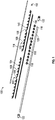
- FIG. 1 shows an exploded view of a sensor streamer section 100 in accordance with an embodiment.
- Sensor streamer includes a plurality of harness modules 102 which, as described further below, each include a plurality of geophysical sensors 104 and a sensor node 106 interconnected via cables disposed within a cable harness 108 (e.g. cables 702-1, 702-2, Figure 7 , not visible in Figure 1 ).
- Harness modules 102 may be prefabricated as described further below in conjunction with Figure 23 . The prefabricated harness modules 102 may then be coupled together and incorporated in sensor streamer section 100. In at least some embodiments a harness module 102 may be about 6.25 meters long.
- Geophysical sensors 104 may include, by way of example, hydrophones, geophones and accelerometers or other particle motion sensors.
- Cable harness 108 may be described further below.
- a sensor streamer may include other numbers of harness modules 102.
- a sensor streamer 10 may include sixteen harness modules 102. Harness modules 102 may be connected together as described further below.
- Cable harness 108 may also include a plurality of cables (e.g. cables 704, Figure 7 , not visible in Figure 1 ) to convey data obtained from the geophysical sensors 104, via sensor node 106 to other sensor nodes, in daisy-chain fashion as described below, or to a backbone node 112, also described below.
- backbone node 112 may provide telemetry circuits such as packet switches, as described further below, to communicate the data from the geophysical sensors 104 to data processing equipment onboard a survey vessel (not shown).
- Sensor streamer section 100 may also include a backbone 114 supplying electrical and optical power to the sensors 102.
- Backbone 114 may extend the length of sensor streamer section 100 which, in at least some example embodiments, may be about 100 meters.
- Strength members 116 may be included in a sensor streamer section 100 to carry the load when a geophysical survey streamer comprising sensor streamer sections 100 is towed in a water body during a geophysical survey.
- a plurality of spacers 118 may be disposed along the length of sensor streamer section 100 to support the cable harness 108 and strength members 116 and, in at least some embodiments, protect the geophysical sensors 104, as will be described further below.
- spacers 118 may comprise an engineered thermoplastic such as an ISOPLAST ® engineered polymer from Lubrizol Corporation, Wickliffe, OH, USA.
- a streamer skin 120 may be disposed as an envelope about the harness modules 102, spacers 118, strength members 116, backbone 114 and backbone node 112. End connectors 122 may be provided to interface the backbone node 112 to connections to data processing equipment on board the survey vessel or to additional sensor streamer sections 100 coupled together in a geophysical survey streamer, as described further below.
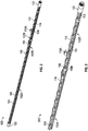
- FIG. 2 shows a cutaway view of a sensor streamer section 100 in accordance with an embodiment.
- two coupled harness modules 102A, 102B are shown (a connection therebetween is not visible in Figure 2 ).
- any number of harness modules 102 may be coupled together within a sensor streamer section 100.
- spacers have been omitted to show the geophysical sensors 104 and sensor node 106 included in harness module 102A.
- Spacers 118 are shown in conjunction with harness module 102B which obscures the view of geophysical sensors 104 attached to harness module 102B.
- One spacer, 118A is shown in exploded view to show the relationship of a geophysical sensor 104 disposed within an interior of spacer 118A.
- Backbone 114 is disposed within a trench (not visible in Figure 2 ) formed in a wall of spacers 118.
- harness modules 102 and strength members 116 may be similarly disposed, although not visible in Figure 2 .
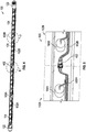
- FIG. 3 shows a portion 300 of a sensor streamer section in accordance with an embodiment. Similar to Figure 2 , a portion of harness module 102A is shown without spacers in place where geophysical sensors 104 are visible, and a harness module 102B is shown in conjunction with spacers in place wherein geophysical sensors 104 may be disposed in an interior volume of spacers 118. A connection between harness modules 102A and 102B not visible in Figure 3 is shown in Figures 4 and 5 . Further, a sensor node 106 may similarly be disposed within an interior volume of a spacer 118B. Strength member 116 may be disposed within another trench (not visible in Figure 3 ) formed in a wall of spacers 118. The structure of spacers 118 in accordance with various embodiments will be further described in conjunction with Figures 15-21 below.
- FIG 4 shows cutaway view of a sensor streamer section 100.
- a backbone 114, strength member 116, and spacers 118 have been omitted so the layout of harness modules 102 may be better appreciated.
- Each harness module 102 may have twelve geophysical sensors 104 coupled in two groups as described further below, to a corresponding sensor node 106.
- the exemplary embodiment of sensor streamer section 100 includes two harness modules 102A, 102B similar to Figure 2 .
- the harness modules 102A, 102B may be coupled together at a connection 402.
- connection 402 may include interconnects for cables 502A in harness module 102A and 502B in harness module 102B.
- Cables 502A, 502B may include electrical cables, optical cables or a combination thereof. Cables 502A may be connected to a sensor node 106A in harness module 102A and carry data from sensor node 106A.
- the data from a sensor node 106 may include data originating with the geophysical sensors 104, such as geophysical sensor 104A coupled to the corresponding sensor node 106, as well as data originating from sensors in other harness modules coupled together in a sensor streamer section and then in a geophysical survey streamer comprising a plurality of sensor streamer sections coupled together via end connectors 122 ( Figure 4 ).
- the data from sensor node 106B may include data received from sensor node 106A via cables 502A, connection 402 and cables 502B.
- Connection 402 includes a connector 602, which in the example is a female connector, and a connector 604 which is a complementary male connector in this example.
- connectors 602 and 604 in the exemplary embodiment employ a bayonet type fixture, alternative embodiments may employ a screw type fixture to join the two connectors.
- a harness module 102 may have a connector 602 ( Figure 6 ) disposed on a first end and a connector 604 disposed on a second end (neither separately visible in Figure 4 ) to interconnect harness modules 102.
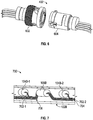
- Figure 7 shows a sensor node interconnection 700 in accordance with at least some embodiments.
- a pair of sensors, 104B-1,104B-2 are shown communicatively coupled to a corresponding sensor node 106B.
- a harness module e.g. harness module 102B may include twelve geophysical sensors 104 coupled, in two groups, as described further below in conjunction with Figure 9 , to a sensor node 106, e.g. sensor node 106B.
- two groups of six sensors are described, other numbers of groups of sensors may be employed. Further the number of sensors in the groups may vary and need not be equal.
- one or more groups may comprise a single sensor.
- the signals received at a sensor node, e.g. sensor node 106B may comprise a sum of the signals from the sensors in the group.
- a geophysical sensor 104B-1 may be a sensor of one of the two groups and geophysical sensor 104B-1 may be a sensor of the other group.
- Each sensor of the first group e.g. 104B-1 may be coupled to a sensor node 106, e.g. sensor node 106B via one of cables 702-1 in harness module 102B.
- sensors of the second group may be coupled to a sensor node 106, such as sensor node 106B, via one of cables 702-2.
- Sensor node 106 may also receive data from a sensor node in a harness module distal to a survey vessel via cables 706. Further, the data output from a sensor node in a harness module proximal to a survey vessel may be coupled to a backbone node for transmission to a subsequent sensor streamer section, or ultimately to a data processing system on the survey vessel.
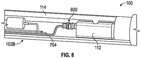
- Figure 8 shows a backbone node connection 800 to a backbone node 112 in a streamer section 100 in accordance with at east some embodiments.
- harness module 102B and sensor node 106B as the harness module sensor node proximal to the survey vessel
- data from the sensor node 106B may be communicatively coupled via cables 704 to a backbone node 112.
- Backbone node 112 may also be coupled to a backbone 114.
- Backbone node 112 may then multiplex that data with data received from a previous streamer section such as a sensor streamer section 100 ( Figures 1 , 2 ) to communicate the data to a next streamer section or to the survey vessel.
- sensors in a harness module 102 may be coupled to a sensor node 106 in two groups with each group disposed on opposite sides of the sensor node.
- a first group 902-1 comprises, in the exemplary embodiment, six geophysical sensors 104-1. Each geophysical sensor 104-1 may be spliced (as shown below in conjunction with Figure 11 ) onto a corresponding cable 702-1 coupled to sensor node 106.
- a second group 902-2 comprises, by way of example, six geophysical sensors 104-2. Each geophysical sensor 104-2 may be spliced onto a cable 702-2 coupled to sensor node 106.
- cables 702-1 comprise cables coupling geophysical sensors 104-1 in group 902-1 ( Figure 9 ) to sensor node 106.
- cables 702-2 comprise cables coupling geophysical sensors 104-2 in group 902-2 ( Figure 9 ) to sensor node 106.
- two groups of six sensors each are employed.
- other numbers of groups comprising various numbers of sensors each may be employed in accordance with the principles of the disclosure.
- a sensor node 106 may receive data from other sensor nodes in harness modules distal to the survey vessel and coupled together as previously described to make up a sensor streamer section.
- cables 706 may couple sensor node 106 to another sensor node distal to the survey vessel and cables 708 may couple sensor node 106 to another sensor node proximal to the survey vessel.
- connectors 602 and 604 ( Figure 9 ) are shown disposed on first and second ends of harness module 102, as described above.
- FIG 11 shows sensor splices 1100 in accordance with at least some embodiments.
- Geophysical sensors 104 may be spliced onto a cable coupled to a sensor node 106 (not shown in Figure 11 ), as previously described.
- Splices 1100 connect sensor leads 1102 to cables 702 coupled to a sensor node 106 (not shown in Figure 11 ).
- Sensor leads 1102 may include power input and sensor signal output cables, and may be electrical or optical as appropriate to the particular sensor embodiment.
- each geophysical sensor 104 may be coupled to a sensor node 106 and communicate data to the sensor node.
- data from a geophysical sensor 104 may be either in digital form or analog form.
- Splices 1000 may be fabricated by soldering or crimping, for example, in the case of electrical cables, and by fusion splicing, for example, for optical cables. Splices 1000 may be sealed with, e.g. heat-shrink tubing. Further, in at least some embodiments, heat-shrink tubing with a heat activated adhesive may be used. In still other embodiments, cables may be sealed by over molding.
- a cable sleeve 1200 may be pulled over the cables 702 (not visible in Figure 12 ) in fabricating a cable harness 108.
- a cable sleeve 1200 may be disposed about the cables 702 included in a cable harness 108.
- a cable sleeve 1200 bundles the cables in the cable harness, and provides protection.
- a self-wrap cable sleeve may be used in conjunction with cable sleeve 1200 in at least some embodiments.
- a twist-in sleeve may be used.
- a woven sleeve with tape and/or castings may be used.
- FIG. 13-16 various spacer embodiments and a sensor streamer section configuration in conjunction therewith are shown.
- the exemplary spacer embodiments in Figures 13-16 may be used to provide one or more of the spacers 118 as described above.
- Figure 13 shows a spacer 1300 in accordance with at least some embodiments.
- Spacer 1300 may comprise two parts, portion 1302 and portion 1304, which may allow for easy assembly of a sensor streamer section 100 ( Figures 1 , 2 ).
- Bodies 1306 and 1308 of portions 1302 and 1304, respectively, may define an interior volume portion 1310 which, when the bodies are assembled, provides an interior volume of a spacer 1300 into which a geophysical sensor 104 may be disposed, as previously described.
- trenches 1312 and 1314 may be formed within walls 1306 and 1308 of portions 1302 and 1304 for receiving a cable harness 108 (not shown in Figure 13 ) and a strength member 116 (not shown in Figure 13 ), respectively, as described further below.
- Trenches 1312 and 1314 may provide a passageway for the cable harness and/or strength member along a length of a harness module 102 ( Figures 1 , 2 ), for example, in which spacers 118 in Figures 1 and 2 comprise a spacer 1300.
- bodies 1306 and 1308 may comprise an engineered thermoplastic such as an ISOPLAST ® engineered polymer from Lubrizol Corporation, Wickliffe, OH, USA.
- FIG 14 shows a spacer 1400 in accordance with at least some embodiments.
- Spacer 1400 is shown having a unitary construction. However, in an alternative embodiment, it may be constructed in two parts, similar to spacer 1300 ( Figure 13 ).
- Spacer 1400 may have trenches 1412 and 1414 formed in a wall 1406 of spacer 1400.
- a strength member (not shown in Figure 14 ) may be disposed in a trench 1412.
- a cable harness 108 may be disposed within a trench 1414 (not visible in Figure 14 ). Further a backbone 114 may be disposed within a trench 1414.
- trenches 1412 and 1414 may provide a passageway for the cable harness and/or strength member along a length of a harness module 102 in Figures 1 , 2 , for example, in which spacers 118 comprise a spacer 1400.
- the disposition of cable harnesses and backbone within trenches in the wall of a spacer in accordance with the disclosed principles, as shown in Figure 14 may facilitate the assembly of a sensor streamer section in that the cable harnesses and backbone need not be manually threaded through holes in a spacer.
- An interior surface1408 of wall 1406 may define an interior volume 1410 into which a geophysical sensor 104 may be placed, similar to the interior volume 1310 of spacer 1300 ( Figure 13 ).
- Figure 15 shows a spacer 1500 including further features that may be incorporated therewith.
- Spacer 1500 includes trenches 1412 and 1414 similar to spacer 1400 ( Figure 1400).
- a trench 1414 may be provided with a groove 1502 for receiving a cover 1504.
- Cover 1504 may protect a cable harness 108 or backbone 114 (not shown in Figure 15 , for clarity) disposed within, as described in conjunction with Figure 14 .
- FIG 16 shows a spacer 1600 in accordance with at least some alternative embodiments.
- Spacer 1600 includes a trench 1602 formed within a wall 1608 of spacer 1600 for receiving a strength member 116 (not shown in Figure 16 ) as previously described.
- Trench 1602 includes a spike 1604 which may help retain a strength member (not shown in Figure 16 ) disposed within trench 1602, and, in operation, may help transfer towing forces to the spacer.
- trench 1606 within wall 1608 for receiving a cable harness 108 or backbone 114 may be angled along a length of spacer 1600. Angling the trench 1606 may help protect the cable harness 108 or backbone 114 disposed within.
- Figure 17 shows a portion 1700 of a sensor streamer section, illustrating the various spacers 1400-1600 disposed within.
- spacer 1400 is shown in an exploded view.
- portion 1700 includes a spacer 1702 having holes 1704 disposed through wall 1706 for passing a strength member 116 (not shown in Figure 17 ) and holes (not visible in Figure 17 ) for passing a cable harness 108 or backbone 114.
- Figures 18-21 show further spacer embodiments and a sensor streamer configuration in conjunction therewith.
- the exemplary spacer embodiments in Figures 18-20 may be used to provide one or more of the spacers 118 as described above.
- a spacer 1800 is shown.
- Spacer 1800 includes a trench 1802 formed in a wall 1804 of spacer 1800 for receiving a strength member 116 (not shown in Figure 18 ).
- Trench 1802 may be angled along a length of spacer 1800 to increase the friction between the strength member and spacer 1800. Similar to the spike 1604 ( Figure 16 ), this may also help to transfer towing forces to the spacer when in operation.
- the angle is provided by a "Vee" shape of trench 1802.
- other shapes may be used, -- for example, a horizontally oriented "S-shape" having continuously varying angle along the length of the spacer 1800.
- FIG 19 shows a spacer 1900 in accordance with at least some alternative embodiments.
- Spacer 1900 may include a trench 1902 having an indentation 1904 configured to receive and engage with a stop 1906 affixed on a strength member 116.
- Stop 1906 may be configured to snap into indentation 1904.
- stop 1906 may be cemented into indentation 1904 with a suitable adhesive material or, may be retained in indentation 1904 using a screw (not shown in Figure 19 ).
- Figure 20 shows an exploded view of a spacer 2000 in accordance with at least some other alternative embodiments.
- Spacer 2000 includes a body 2002 having wall 2006 and an interior wall surface 2004 defining an interior volume 2008.
- a geophysical sensor 104 (not shown in Figure 20 ) may be disposed within interior volume 2008, as previously described.
- Trenches 2010 for receiving strength members 116, cable harnesses 108 and a backbone 114, as described above, may be formed within the wall 2006.
- Trenches 2010 may have an oval shape wherein a thickness of wall 2006 may be greater than might otherwise obtain with trenches having a circular shape.
- a cover 2012 may be disposed over body 2002 to help retain the strength members, cable harnesses and backbones (none shown in Figure 20 ) within trenches 2010, as shown in Figure 21 .
- Figure 21 shows a sensor streamer section portion 2100 illustrating the various spacers 1800-2100 disposed within.
- Spacer 2100 is shown with cover 2012 in position over body 2002.
- stop 1906 is shown positioned within indentation 1904 (not visible in Figure 21 ).
- a cable harness 108 may be disposed in a trench, e.g. a trench 1314 ( Figure 13 ).
- Strength member 116 may also be disposed within a trench 1802 formed in the wall of spacer 1800, as described above in conjunction with Figure 18 .
- FIG 22 provides a block diagram of a sensor streamer section communication system 2200 (hereinafter simply communication system 2200) in accordance with at least some embodiments.
- Communication system 2200 may be used in a sensor streamer section comprising a plurality of harness modules 102 as described above in conjunction with, inter alia, Figures 1 and 2 .
- three sensor nodes, 106-1, 106-2 and 106-3, are shown, however various numbers of sensor nodes 106 may be included in a sensor streamer section in conjunction with each harness module 102 ( Figures 1 , 2 ).
- a communication system 2200 may include sixteen sensor nodes 106 in conjunction with sixteen harness modules 102.
- sensor node 106-3 may be a sensor node coupled to a backbone node 112. Between sensor nodes 106-2 and 106-3, various numbers of intermediate sensor nodes 106 (not shown in Figure 22 ) may be coupled in daisy chain fashion.
- a sensor node 106-2 may be coupled to a first connector, e.g. a connector 604 ( Figures 6 and 9 ), at a first end of a harness module 102 ( Figures 1 , 2 ).
- sensor node 106-2 may also be coupled to a second connector, e.g. a connector 602 ( Figures 6 and 9 ), at a second end of the harness module 102 ( Figures 1 , 2 ).
- the example sensor node 106-2 is configured to couple to sensor nodes 106-1 and 106-3 in their respective harness modules 102 ( Figures 1 , 2 ).
- Sensor nodes 106 may be configured to receive data from sensors 104 (not shown in Figure 22 ) as previously described.
- Analog data 2202 may be received, for example, from geophysical sensors 104 (not shown in figure 22 ) comprising hydrophones and accelerometers.
- Digital data 2204 may be received from geophysical sensors 104 comprising, for example, MEMS sensors and geophones.
- Analog data may be digitized by an analog-to-digital (A/D) converter or ADC 2206 for subsequent transmission to data processing equipment on board a survey vessel (not shown in Figure 22 ). Digitized analog data from ADC 2206 and digital data 2204 may be packetized and stored in buffer/retransmit 2208 for transmission, under the control of packet switch 2210, to a subsequent sensor node 106 where it may be aggregated with data from sensors coupled to the subsequent sensor node.
- sensor node 106-2 may be a subsequent sensor node with respect to sensor node 106-1 wherein the data transmitted from sensor node 106-1 is communicated via data link 2212 to sensor node 106-2.
- a sensor streamer section 100 may comprise a plurality of harness modules 102 ( Figure 1 , 2 ) wherein various numbers of sensor nodes 106 (not shown in Figure 22 ) may be coupled together in daisy chain fashion between sensor nodes 106-2 and 106-3.
- data received on a data link 2212 may be aggregated with the digitized analog data 2204 and digital data 2206 received at the respective sensor node 106.
- Sensor node 106-3 which as described above, may be a sensor node proximal to a survey vessel (not shown in Figure 22 ) may be coupled to a backbone node 112.
- Backbone node 112 may provide telemetry services to the sensor streamer section.
- the aggregated data from sensor node 106-3 may be coupled, via data link 2216, to a packet switch 2218 within backbone node 112.
- Packet switch 2218 may also receive aggregated data via data link 2220 from a previous sensor streamer section (not shown in Figure 22 ). Packet switch 2218 may then forward the data to a subsequent sensor streamer section (not shown in Figure 22 ) on data link 2222.
- data link 2222 may couple to a data processing system on board the vessel.
- Data links 2212, 2216, 2220 and 2222 may be electrical, optical or combinations thereof.
- data links 2212 and 2216 may comprise one or more of cables 706 and 704 ( Figures 7 , 10 ), respectively.
- Data link 2220 may be included in a backbone 114 ( Figures 1 , 2 ) which may also include cables to provide redundancy, for example a redundant optical fiber 2230 and a wire pair 2232 for redundant steering control.
- a backbone node 112 may also include a controller 2224 and an auxiliary interface 2226.
- Auxiliary interface 2226 may, for example, receive acoustic positioning data 2228 from acoustic positioning devices (not shown in Figure 22 ) associated with a sensor streamer section employing a communication system 2200.
- Controller 2224 may provide control information to packet switch 2218.
- Controller 2224 may also provide control information to, for example, steering devices (not shown) coupled between sensor streamer sections comprising a seismic streamer. The control information may be based, at least in part, on acoustic positioning data 2228.
- one or more of data links 2212, 2216, 2220 and 2222 may be bi-directional links wherein control information may be transmitted to sensor streamer sections comprising a seismic streamer and positioned distal to the survey vessel.
- backbone node 112 is shown as an integrated unit, in alternative embodiments, backbone node 112 may comprise discrete units within a sensor streamer section 100 ( Figures 1 , 2 ).
- a compass/tilt sensor 2214 may be provided.
- Compass/tilt sensor 2214 may be used to provide data with respect to the orientation of the sensor streamer section incorporating the communication system 2200.
- a compass/tilt sensor 2214 may be used with sensor streamer sections employing geophysical sensors 104 (not shown in Figure 22 ) comprising piezoelectric accelerometer-based motion sensors.
- a compass/tilt sensor 2214 may not be needed with sensor streamer sections employing geophysical sensors 104 (not shown in Figure 22 ) comprising MEMS-based motion sensors, as a DC value from the MEMS-based motion sensor provides a measurement of the gravitational field at the position of the sensor streamer section, which can be used to determine the orientation of the sensor streamer section.
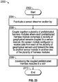
- Figure 23 shows a flow chart of a method 2300 in accordance with at least some embodiments.
- Method 2300 starts at block 2302.
- a sensor streamer section is fabricated by coupling together a plurality of prefabricated harness modules, block 2306, wherein each prefabricated harness module comprises a plurality of geophysical sensors coupled to a sensor node.
- the sensor node is configured to receive data from each of the plurality of geophysical sensors and to forward the data to another sensor node in another one of the prefabricated harness modules.
- the coupled prefabricated harness modules are enveloped in a skin.
- the skin may be filled with a gel.
- fabricating a sensor streamer section may further comprise disposing each geophysical sensor in each harness module in an interior volume of a spacer, and disposing the cable harness in a trench formed in a wall of each spacer. Further, fabricating a sensor streamer section may include disposing a strength member in another trench formed in the wall of each spacer.
- Fabricating a sensor streamer section may further include coupling one of the prefabricated harness modules to a backbone node configured to forward data received from one of the prefabricated harness modules to another sensor streamer section or to a survey vessel.
- the harness modules may be prefabricated by, for each geophysical sensor in each prefabricated harness module, splicing a lead from the geophysical sensor to a cable disposed within a cable harness comprising a plurality of cables, the cable coupled to a corresponding one of the sensor nodes.
- Splicing may include soldering, crimping in the case of electrical cables, or fusion splicing in the case of optical cables.
- prefabricating each harness module may further comprise attaching a first connector on a first end of the prefabricated harness module and a second connector on a second end of the prefabricated harness module, the first and second connectors configured to couple together the harness modules, and wherein when coupled together, data from a sensor node in a first harness module is configured to communicate data to a sensor node in a second harness module coupled to the first harness module.
- the prefabricating may include disposing a cable sleeve about the cables in the cable harness.
Landscapes
- Physics & Mathematics (AREA)
- Life Sciences & Earth Sciences (AREA)
- Engineering & Computer Science (AREA)
- Remote Sensing (AREA)
- Acoustics & Sound (AREA)
- Environmental & Geological Engineering (AREA)
- Geology (AREA)
- General Life Sciences & Earth Sciences (AREA)
- General Physics & Mathematics (AREA)
- Geophysics (AREA)
- Geophysics And Detection Of Objects (AREA)
Abstract
Description
- This disclosure is related generally to the field of marine surveying. Marine surveying can include, for example, seismic and/or electromagnetic surveying, among others. For example, this disclosure may have applications in marine surveying, in which one or more source elements are used to generate wave-fields, and sensors-either towed or ocean bottom or otherwise-receive energy generated by the source elements and affected by the interaction with the subsurface formation. The sensors thereby collect survey data which can be useful in the discovery and/or extraction of hydrocarbons from subsurface formations.
- Some related art approaches to the manufacture of seismic streamers can be work-intensive. A large part of the work can be related to the insertion and splicing of the sensors and sensor network electronics into a section of the seismic streamer. This can include threading of the local wiring through the spacers and splicing in each sensor and electronics unit into a local wire bundle at the correct position. The work may be manual, and it may be tedious due to limited space in the streamer. Consequently, methods and systems that ameliorate the manual steps and and/or modularize the assembly of seismic streamers provide a competitive advantage in the art.
- For a detailed description of exemplary embodiments of the invention, reference will now be made to the accompanying drawings in which:
-
Figure 1 shows an exploded view of a sensor streamer section in accordance with an embodiment; -
Figure 2 shows cutaway view of a streamer section in accordance with an embodiment; -
Figure 3 shows a portion of a sensor streamer section in accordance with an embodiment; -
Figure 4 shows a cutaway view of a sensor streamer section in accordance with an embodiment; -
Figure 5 shows a harness module interconnection in accordance with an embodiment; -
Figure 6 shows a connector in accordance with an embodiment; -
Figure 7 shows a sensor node interconnection in accordance with an embodiment; -
Figure 8 shows a backbone node connection in accordance with at least some embodiments; -
Figure 9 shows a harness module in accordance with an embodiment; -
Figure 10 shows a sensor node cable configuration in accordance with an embodiment; -
Figure 11 shows sensor splices in accordance with an embodiment; -
Figure 12 shows a cable sleeve in accordance with an with an embodiment; -
Figure 13 shows an exploded view of a spacer in accordance with an embodiment; -
Figure 14 shows a spacer in accordance with an embodiment; -
Figure 15 shows further features of a spacer in accordance with an embodiment; -
Figure 16 shows a spacer in accordance with another embodiment; -
Figure 17 shows a sensor streamer section portion in accordance with an embodiment; -
Figure 18 shows a spacer in accordance with another embodiment -
Figure 19 shows a spacer in accordance with another embodiment; -
Figure 20 shows a spacer in accordance with another embodiment; -
Figure 21 shows a sensor streamer section portion in accordance with an embodiment; -
Figure 22 shows a block diagram of a sensor streamer section data communication system in accordance with an embodiment; and -
Figure 23 shows a flow chart of a method in accordance with an embodiment. - Certain terms are used throughout the following description and claims to refer to particular system components. As one skilled in the art will appreciate, computer companies may refer to a component by different names. This document does not intend to distinguish between components that differ in name but not function. In the following discussion and in the claims, the terms "including" and "comprising" are used in an open-ended fashion, and thus should be interpreted to mean "including, but not limited to...." Also, the term "couple" or "couples" is intended to mean either an indirect, direct, optical or wireless electrical connection. Thus, if a first device couples to a second device, that connection may be through a direct electrical connection, through an indirect electrical connection via other devices and connections, through an optical electrical connection, or through a wireless electrical connection.
- The following discussion is directed to various embodiments of the invention. Although one or more of these embodiments may be preferred, the embodiments disclosed should not be interpreted, or otherwise used, as limiting the scope of the disclosure, including the claims. In addition, one skilled in the art will understand that the following description has broad application, and the discussion of any embodiment is meant only to be exemplary of that embodiment, and not intended to intimate that the scope of the disclosure, including the claims, is limited to that embodiment.
-
Figure 1 shows an exploded view of asensor streamer section 100 in accordance with an embodiment. Sensor streamer includes a plurality ofharness modules 102 which, as described further below, each include a plurality ofgeophysical sensors 104 and asensor node 106 interconnected via cables disposed within a cable harness 108 (e.g. cables 702-1, 702-2,Figure 7 , not visible inFigure 1 ).Harness modules 102 may be prefabricated as described further below in conjunction withFigure 23 . The prefabricatedharness modules 102 may then be coupled together and incorporated insensor streamer section 100. In at least some embodiments aharness module 102 may be about 6.25 meters long.Geophysical sensors 104 may include, by way of example, hydrophones, geophones and accelerometers or other particle motion sensors. The principles of the disclosure may be employed with any type of sensor typically employed in a seismic geophysical survey.Cable harness 108 will also be described further below. Although the exemplarysensor streamer section 100 is shown, for ease of illustration with twoharness modules 102, a sensor streamer may include other numbers ofharness modules 102. For example, in at least some embodiments, a sensor streamer 10 may include sixteenharness modules 102.Harness modules 102 may be connected together as described further below.Cable harness 108 may also include a plurality of cables (e.g. cables 704,Figure 7 , not visible inFigure 1 ) to convey data obtained from thegeophysical sensors 104, viasensor node 106 to other sensor nodes, in daisy-chain fashion as described below, or to abackbone node 112, also described below. When employed in a geophysical survey,backbone node 112 may provide telemetry circuits such as packet switches, as described further below, to communicate the data from thegeophysical sensors 104 to data processing equipment onboard a survey vessel (not shown).Sensor streamer section 100 may also include abackbone 114 supplying electrical and optical power to thesensors 102.Backbone 114 may extend the length ofsensor streamer section 100 which, in at least some example embodiments, may be about 100 meters.Strength members 116 may be included in asensor streamer section 100 to carry the load when a geophysical survey streamer comprisingsensor streamer sections 100 is towed in a water body during a geophysical survey. A plurality ofspacers 118 may be disposed along the length ofsensor streamer section 100 to support thecable harness 108 andstrength members 116 and, in at least some embodiments, protect thegeophysical sensors 104, as will be described further below. In at least some embodiments,spacers 118 may comprise an engineered thermoplastic such as an ISOPLAST® engineered polymer from Lubrizol Corporation, Wickliffe, OH, USA. Astreamer skin 120 may be disposed as an envelope about theharness modules 102,spacers 118,strength members 116,backbone 114 andbackbone node 112.End connectors 122 may be provided to interface thebackbone node 112 to connections to data processing equipment on board the survey vessel or to additionalsensor streamer sections 100 coupled together in a geophysical survey streamer, as described further below. -
Figure 2 shows a cutaway view of asensor streamer section 100 in accordance with an embodiment. InFigure 2 , two coupledharness modules Figure 2 ). In other embodiments, any number ofharness modules 102 may be coupled together within asensor streamer section 100. In conjunction withharness module 102A, spacers have been omitted to show thegeophysical sensors 104 andsensor node 106 included inharness module 102A.Spacers 118 are shown in conjunction withharness module 102B which obscures the view ofgeophysical sensors 104 attached to harnessmodule 102B. One spacer, 118A, is shown in exploded view to show the relationship of ageophysical sensor 104 disposed within an interior ofspacer 118A.Backbone 114 is disposed within a trench (not visible inFigure 2 ) formed in a wall ofspacers 118. As will be described further below,harness modules 102 andstrength members 116 may be similarly disposed, although not visible inFigure 2 . - The structure of a sensor streamer section in accordance with the principles of the disclosure may be further appreciated by referring to
Figure 3. Figure 3 shows aportion 300 of a sensor streamer section in accordance with an embodiment. Similar toFigure 2 , a portion ofharness module 102A is shown without spacers in place wheregeophysical sensors 104 are visible, and aharness module 102B is shown in conjunction with spacers in place whereingeophysical sensors 104 may be disposed in an interior volume ofspacers 118. A connection betweenharness modules Figure 3 is shown inFigures 4 and 5 . Further, asensor node 106 may similarly be disposed within an interior volume of aspacer 118B.Strength member 116 may be disposed within another trench (not visible inFigure 3 ) formed in a wall ofspacers 118. The structure ofspacers 118 in accordance with various embodiments will be further described in conjunction withFigures 15-21 below. - Turning to
Figure 4, Figure 4 shows cutaway view of asensor streamer section 100. InFigure 4 , abackbone 114,strength member 116, andspacers 118 have been omitted so the layout ofharness modules 102 may be better appreciated. Eachharness module 102 may have twelvegeophysical sensors 104 coupled in two groups as described further below, to acorresponding sensor node 106. The exemplary embodiment ofsensor streamer section 100 includes twoharness modules Figure 2 . Theharness modules connection 402. Referring toFigure 5 , showing aharness module interconnection 500 in accordance with an embodiment,connection 402 may include interconnects forcables 502A inharness module harness module 102B.Cables Cables 502A may be connected to asensor node 106A inharness module 102A and carry data fromsensor node 106A. As described further below in conjunction withFigure 22 , in operation, the data from asensor node 106 may include data originating with thegeophysical sensors 104, such asgeophysical sensor 104A coupled to the correspondingsensor node 106, as well as data originating from sensors in other harness modules coupled together in a sensor streamer section and then in a geophysical survey streamer comprising a plurality of sensor streamer sections coupled together via end connectors 122 (Figure 4 ). For example, considering the twoharness modules Figure 4 ), the data fromsensor node 106B may include data received fromsensor node 106A viacables 502A,connection 402 andcables 502B. This data may be multiplexed with data originating withgeophysical sensors 104 coupled tosensor node 106B, such asgeophysical sensor 104B, as may be seen inFigure 7 , below.Figure 6 showsconnection 402 in further detail.Connection 402 includes aconnector 602, which in the example is a female connector, and aconnector 604 which is a complementary male connector in this example. Althoughconnectors Figure 4 , aharness module 102 may have a connector 602 (Figure 6 ) disposed on a first end and aconnector 604 disposed on a second end (neither separately visible inFigure 4 ) to interconnectharness modules 102. - Turning to
Figure 7, Figure 7 shows asensor node interconnection 700 in accordance with at least some embodiments. InFigure 7 a pair of sensors, 104B-1,104B-2 are shown communicatively coupled to acorresponding sensor node 106B. As discussed above, in at least some embodiments, a harness module,e.g. harness module 102B may include twelvegeophysical sensors 104 coupled, in two groups, as described further below in conjunction withFigure 9 , to asensor node 106,e.g. sensor node 106B. Although in the example embodiments, two groups of six sensors are described, other numbers of groups of sensors may be employed. Further the number of sensors in the groups may vary and need not be equal. In at least some embodiments, one or more groups may comprise a single sensor. And, in at least some embodiments, the signals received at a sensor node,e.g. sensor node 106B may comprise a sum of the signals from the sensors in the group. Thus, ageophysical sensor 104B-1 may be a sensor of one of the two groups andgeophysical sensor 104B-1 may be a sensor of the other group. Each sensor of the first group e.g. 104B-1, may be coupled to asensor node 106,e.g. sensor node 106B via one of cables 702-1 inharness module 102B. Similarly, sensors of the second group may be coupled to asensor node 106, such assensor node 106B, via one of cables 702-2.Sensor node 106 may also receive data from a sensor node in a harness module distal to a survey vessel viacables 706. Further, the data output from a sensor node in a harness module proximal to a survey vessel may be coupled to a backbone node for transmission to a subsequent sensor streamer section, or ultimately to a data processing system on the survey vessel. - Referring to
Figure 8, Figure 8 shows abackbone node connection 800 to abackbone node 112 in astreamer section 100 in accordance with at east some embodiments. Taking, by way of example,harness module 102B andsensor node 106B as the harness module sensor node proximal to the survey vessel, then data from thesensor node 106B (Figure 7 ) may be communicatively coupled viacables 704 to abackbone node 112.Backbone node 112 may also be coupled to abackbone 114.Backbone node 112 may then multiplex that data with data received from a previous streamer section such as a sensor streamer section 100 (Figures 1 ,2 ) to communicate the data to a next streamer section or to the survey vessel. - As previously described, sensors in a
harness module 102 may be coupled to asensor node 106 in two groups with each group disposed on opposite sides of the sensor node. This may be understood by referring toFigure 9 showing aharness module 102 in accordance with at least some embodiments. A first group 902-1 comprises, in the exemplary embodiment, six geophysical sensors 104-1. Each geophysical sensor 104-1 may be spliced (as shown below in conjunction withFigure 11 ) onto a corresponding cable 702-1 coupled tosensor node 106. Similarly, a second group 902-2 comprises, by way of example, six geophysical sensors 104-2. Each geophysical sensor 104-2 may be spliced onto a cable 702-2 coupled tosensor node 106. Thus, referring toFigure 10 , showing a sensornode cable configuration 1000, in the exemplary embodiment, six cables from each group are connected to asensor node 106. Thus, cables 702-1 comprise cables coupling geophysical sensors 104-1 in group 902-1 (Figure 9 ) tosensor node 106. Similarly, cables 702-2 comprise cables coupling geophysical sensors 104-2 in group 902-2 (Figure 9 ) tosensor node 106. As described above, in this example embodiment, two groups of six sensors each are employed. However, other numbers of groups comprising various numbers of sensors each may be employed in accordance with the principles of the disclosure. Further, as also described above, asensor node 106 may receive data from other sensor nodes in harness modules distal to the survey vessel and coupled together as previously described to make up a sensor streamer section. Thuscables 706 may couplesensor node 106 to another sensor node distal to the survey vessel andcables 708 may couplesensor node 106 to another sensor node proximal to the survey vessel. In this aspect,connectors 602 and 604 (Figure 9 ) are shown disposed on first and second ends ofharness module 102, as described above. -
Figure 11 shows sensor splices 1100 in accordance with at least some embodiments.Geophysical sensors 104 may be spliced onto a cable coupled to a sensor node 106 (not shown inFigure 11 ), as previously described.Splices 1100 connect sensor leads 1102 tocables 702 coupled to a sensor node 106 (not shown inFigure 11 ). Sensor leads 1102 may include power input and sensor signal output cables, and may be electrical or optical as appropriate to the particular sensor embodiment. Thus, eachgeophysical sensor 104 may be coupled to asensor node 106 and communicate data to the sensor node. As described further below in conjunction withFigure 22 , data from ageophysical sensor 104 may be either in digital form or analog form. For example, data from a micro-electromechanical system (MEMS) sensor or a geophone may be in digital form, and data from a hydrophone or accelerometer may be in analog form.Splices 1000 may be fabricated by soldering or crimping, for example, in the case of electrical cables, and by fusion splicing, for example, for optical cables.Splices 1000 may be sealed with, e.g. heat-shrink tubing. Further, in at least some embodiments, heat-shrink tubing with a heat activated adhesive may be used. In still other embodiments, cables may be sealed by over molding. Referring toFigure 12 , acable sleeve 1200 may be pulled over the cables 702 (not visible inFigure 12 ) in fabricating acable harness 108. In other words, acable sleeve 1200 may be disposed about thecables 702 included in acable harness 108. Acable sleeve 1200 bundles the cables in the cable harness, and provides protection. A self-wrap cable sleeve may be used in conjunction withcable sleeve 1200 in at least some embodiments. In other embodiments, a twist-in sleeve may be used. In still other embodiments, a woven sleeve with tape and/or castings may be used. - In
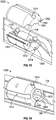
Figures 13-16 various spacer embodiments and a sensor streamer section configuration in conjunction therewith are shown. The exemplary spacer embodiments inFigures 13-16 may be used to provide one or more of thespacers 118 as described above. Turning toFigure 13, Figure 13 shows aspacer 1300 in accordance with at least some embodiments.Spacer 1300 may comprise two parts,portion 1302 andportion 1304, which may allow for easy assembly of a sensor streamer section 100 (Figures 1 ,2 ).Bodies portions interior volume portion 1310 which, when the bodies are assembled, provides an interior volume of aspacer 1300 into which ageophysical sensor 104 may be disposed, as previously described. In other words, whenportions interior volume portions 1310, are exposed, for ease of disposition of asensor node 106 therein.Further trenches walls portions Figure 13 ) and a strength member 116 (not shown inFigure 13 ), respectively, as described further below.Trenches Figures 1 ,2 ), for example, in which spacers 118 inFigures 1 and2 comprise aspacer 1300. In at least some embodiments,bodies -
Figure 14 shows aspacer 1400 in accordance with at least some embodiments.Spacer 1400 is shown having a unitary construction. However, in an alternative embodiment, it may be constructed in two parts, similar to spacer 1300 (Figure 13 ).Spacer 1400 may havetrenches wall 1406 ofspacer 1400. A strength member (not shown inFigure 14 ) may be disposed in atrench 1412. Acable harness 108 may be disposed within a trench 1414 (not visible inFigure 14 ). Further abackbone 114 may be disposed within atrench 1414. Similar tospacer 1300,trenches harness module 102 inFigures 1 ,2 , for example, in which spacers 118 comprise aspacer 1400. The disposition of cable harnesses and backbone within trenches in the wall of a spacer in accordance with the disclosed principles, as shown inFigure 14 , may facilitate the assembly of a sensor streamer section in that the cable harnesses and backbone need not be manually threaded through holes in a spacer. An interior surface1408 ofwall 1406 may define aninterior volume 1410 into which ageophysical sensor 104 may be placed, similar to theinterior volume 1310 of spacer 1300 (Figure 13 ). -
Figure 15 shows aspacer 1500 including further features that may be incorporated therewith.Spacer 1500 includestrenches trench 1414 may be provided with agroove 1502 for receiving acover 1504.Cover 1504 may protect acable harness 108 or backbone 114 (not shown inFigure 15 , for clarity) disposed within, as described in conjunction withFigure 14 . -
Figure 16 shows aspacer 1600 in accordance with at least some alternative embodiments.Spacer 1600 includes atrench 1602 formed within awall 1608 ofspacer 1600 for receiving a strength member 116 (not shown inFigure 16 ) as previously described.Trench 1602 includes aspike 1604 which may help retain a strength member (not shown inFigure 16 ) disposed withintrench 1602, and, in operation, may help transfer towing forces to the spacer. Further,trench 1606 withinwall 1608 for receiving acable harness 108 or backbone 114 (neither shown inFigure 16 for clarity) may be angled along a length ofspacer 1600. Angling thetrench 1606 may help protect thecable harness 108 orbackbone 114 disposed within. -
Figure 17 shows aportion 1700 of a sensor streamer section, illustrating the various spacers 1400-1600 disposed within. InFigure 17 ,spacer 1400 is shown in an exploded view. Further,portion 1700 includes aspacer 1702 havingholes 1704 disposed throughwall 1706 for passing a strength member 116 (not shown inFigure 17 ) and holes (not visible inFigure 17 ) for passing acable harness 108 orbackbone 114. -
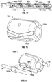
Figures 18-21 show further spacer embodiments and a sensor streamer configuration in conjunction therewith. The exemplary spacer embodiments inFigures 18-20 may be used to provide one or more of thespacers 118 as described above. Turning toFigure 18 , aspacer 1800 is shown.Spacer 1800 includes atrench 1802 formed in awall 1804 ofspacer 1800 for receiving a strength member 116 (not shown inFigure 18 ).Trench 1802 may be angled along a length ofspacer 1800 to increase the friction between the strength member andspacer 1800. Similar to the spike 1604 (Figure 16 ), this may also help to transfer towing forces to the spacer when in operation. In theexample trench 1802, the angle is provided by a "Vee" shape oftrench 1802. However, other shapes may be used, -- for example, a horizontally oriented "S-shape" having continuously varying angle along the length of thespacer 1800. -
Figure 19 shows aspacer 1900 in accordance with at least some alternative embodiments.Spacer 1900 may include atrench 1902 having anindentation 1904 configured to receive and engage with astop 1906 affixed on astrength member 116.Stop 1906 may be configured to snap intoindentation 1904. Alternatively, stop 1906 may be cemented intoindentation 1904 with a suitable adhesive material or, may be retained inindentation 1904 using a screw (not shown inFigure 19 ). -
Figure 20 shows an exploded view of aspacer 2000 in accordance with at least some other alternative embodiments.Spacer 2000 includes abody 2002 havingwall 2006 and aninterior wall surface 2004 defining aninterior volume 2008. When incorporated into a sensor streamer section, a geophysical sensor 104 (not shown inFigure 20 ) may be disposed withininterior volume 2008, as previously described.Trenches 2010 for receivingstrength members 116, cable harnesses 108 and abackbone 114, as described above, may be formed within thewall 2006.Trenches 2010 may have an oval shape wherein a thickness ofwall 2006 may be greater than might otherwise obtain with trenches having a circular shape. Acover 2012 may be disposed overbody 2002 to help retain the strength members, cable harnesses and backbones (none shown inFigure 20 ) withintrenches 2010, as shown inFigure 21 . -
Figure 21 shows a sensorstreamer section portion 2100 illustrating the various spacers 1800-2100 disposed within.Spacer 2100 is shown withcover 2012 in position overbody 2002. Similarly stop 1906 is shown positioned within indentation 1904 (not visible inFigure 21 ). Acable harness 108 may be disposed in a trench, e.g. a trench 1314 (Figure 13 ).Strength member 116 may also be disposed within atrench 1802 formed in the wall ofspacer 1800, as described above in conjunction withFigure 18 . - To further appreciate the foregoing principles of the disclosure,
Figure 22 provides a block diagram of a sensor streamer section communication system 2200 (hereinafter simply communication system 2200) in accordance with at least some embodiments.Communication system 2200 may be used in a sensor streamer section comprising a plurality ofharness modules 102 as described above in conjunction with, inter alia,Figures 1 and2 . InFigure 22 , three sensor nodes, 106-1, 106-2 and 106-3, are shown, however various numbers ofsensor nodes 106 may be included in a sensor streamer section in conjunction with each harness module 102 (Figures 1 ,2 ). In an exemplary embodiment, acommunication system 2200 may include sixteensensor nodes 106 in conjunction with sixteenharness modules 102. Further, as will be described below, sensor node 106-3 may be a sensor node coupled to abackbone node 112. Between sensor nodes 106-2 and 106-3, various numbers of intermediate sensor nodes 106 (not shown inFigure 22 ) may be coupled in daisy chain fashion. For example, a sensor node 106-2 may be coupled to a first connector, e.g. a connector 604 (Figures 6 and9 ), at a first end of a harness module 102 (Figures 1 ,2 ). And, sensor node 106-2 may also be coupled to a second connector, e.g. a connector 602 (Figures 6 and9 ), at a second end of the harness module 102 (Figures 1 ,2 ). Thus, the example sensor node 106-2 is configured to couple to sensor nodes 106-1 and 106-3 in their respective harness modules 102 (Figures 1 ,2 ). -
Sensor nodes 106 may be configured to receive data from sensors 104 (not shown inFigure 22 ) as previously described.Analog data 2202 may be received, for example, from geophysical sensors 104 (not shown infigure 22 ) comprising hydrophones and accelerometers.Digital data 2204 may be received fromgeophysical sensors 104 comprising, for example, MEMS sensors and geophones. - Analog data may be digitized by an analog-to-digital (A/D) converter or
ADC 2206 for subsequent transmission to data processing equipment on board a survey vessel (not shown inFigure 22 ). Digitized analog data fromADC 2206 anddigital data 2204 may be packetized and stored in buffer/retransmit 2208 for transmission, under the control ofpacket switch 2210, to asubsequent sensor node 106 where it may be aggregated with data from sensors coupled to the subsequent sensor node. Thus, by way of example, sensor node 106-2 may be a subsequent sensor node with respect to sensor node 106-1 wherein the data transmitted from sensor node 106-1 is communicated viadata link 2212 to sensor node 106-2. - As noted above, a sensor streamer section 100 (
Figure 1 ,2 ) may comprise a plurality of harness modules 102 (Figure 1 ,2 ) wherein various numbers of sensor nodes 106 (not shown inFigure 22 ) may be coupled together in daisy chain fashion between sensor nodes 106-2 and 106-3. At eachsuch sensor node 106, data received on adata link 2212 may be aggregated with the digitizedanalog data 2204 anddigital data 2206 received at therespective sensor node 106. Sensor node 106-3, which as described above, may be a sensor node proximal to a survey vessel (not shown inFigure 22 ) may be coupled to abackbone node 112. -
Backbone node 112 may provide telemetry services to the sensor streamer section. The aggregated data from sensor node 106-3 may be coupled, viadata link 2216, to apacket switch 2218 withinbackbone node 112.Packet switch 2218 may also receive aggregated data viadata link 2220 from a previous sensor streamer section (not shown inFigure 22 ).Packet switch 2218 may then forward the data to a subsequent sensor streamer section (not shown inFigure 22 ) ondata link 2222. Alternatively, if the sensor streamer section 100 (Figures 1 ,2 ) is the streamer section proximal to the survey vessel,data link 2222 may couple to a data processing system on board the vessel.Data links data links cables 706 and 704 (Figures 7 ,10 ), respectively.Data link 2220 may be included in a backbone 114 (Figures 1 ,2 ) which may also include cables to provide redundancy, for example a redundantoptical fiber 2230 and awire pair 2232 for redundant steering control. - A
backbone node 112 may also include acontroller 2224 and anauxiliary interface 2226.Auxiliary interface 2226 may, for example, receiveacoustic positioning data 2228 from acoustic positioning devices (not shown inFigure 22 ) associated with a sensor streamer section employing acommunication system 2200.Controller 2224 may provide control information topacket switch 2218.Controller 2224 may also provide control information to, for example, steering devices (not shown) coupled between sensor streamer sections comprising a seismic streamer. The control information may be based, at least in part, onacoustic positioning data 2228. In this respect, one or more ofdata links backbone node 112 is shown as an integrated unit, in alternative embodiments,backbone node 112 may comprise discrete units within a sensor streamer section 100 (Figures 1 ,2 ). - In at least some embodiments of
sensor nodes 106, a compass/tilt sensor 2214 may be provided. Compass/tilt sensor 2214may be used to provide data with respect to the orientation of the sensor streamer section incorporating thecommunication system 2200. For example, a compass/tilt sensor 2214 may be used with sensor streamer sections employing geophysical sensors 104 (not shown inFigure 22 ) comprising piezoelectric accelerometer-based motion sensors. In contrast, a compass/tilt sensor 2214 may not be needed with sensor streamer sections employing geophysical sensors 104 (not shown inFigure 22 ) comprising MEMS-based motion sensors, as a DC value from the MEMS-based motion sensor provides a measurement of the gravitational field at the position of the sensor streamer section, which can be used to determine the orientation of the sensor streamer section. -
Figure 23 shows a flow chart of amethod 2300 in accordance with at least some embodiments.Method 2300 starts atblock 2302. Inblock 2304, a sensor streamer section is fabricated by coupling together a plurality of prefabricated harness modules,block 2306, wherein each prefabricated harness module comprises a plurality of geophysical sensors coupled to a sensor node. The sensor node is configured to receive data from each of the plurality of geophysical sensors and to forward the data to another sensor node in another one of the prefabricated harness modules. Inblock 2308, the coupled prefabricated harness modules are enveloped in a skin. The skin may be filled with a gel. In at least some embodiments, fabricating a sensor streamer section may further comprise disposing each geophysical sensor in each harness module in an interior volume of a spacer, and disposing the cable harness in a trench formed in a wall of each spacer. Further, fabricating a sensor streamer section may include disposing a strength member in another trench formed in the wall of each spacer. - Fabricating a sensor streamer section may further include coupling one of the prefabricated harness modules to a backbone node configured to forward data received from one of the prefabricated harness modules to another sensor streamer section or to a survey vessel.
- The harness modules may be prefabricated by, for each geophysical sensor in each prefabricated harness module, splicing a lead from the geophysical sensor to a cable disposed within a cable harness comprising a plurality of cables, the cable coupled to a corresponding one of the sensor nodes. Splicing may include soldering, crimping in the case of electrical cables, or fusion splicing in the case of optical cables. In at least some embodiments, prefabricating each harness module may further comprise attaching a first connector on a first end of the prefabricated harness module and a second connector on a second end of the prefabricated harness module, the first and second connectors configured to couple together the harness modules, and wherein when coupled together, data from a sensor node in a first harness module is configured to communicate data to a sensor node in a second harness module coupled to the first harness module. Further, the prefabricating may include disposing a cable sleeve about the cables in the cable harness.
- The above discussion is meant to be illustrative of the principles and various embodiments of the present invention. Numerous variations and modifications will become apparent to those skilled in the art once the above disclosure is fully appreciated. For example, various numbers of sensor streamer sections may be coupled in a geophysical survey streamer, and each streamer section may include various numbers of coupled prefabricated harness modules.. It is intended that the following claims be interpreted to embrace all such variations and modifications.
Claims (15)
- A method of fabricating a streamer section comprising:coupling together a plurality of prefabricated harness modules, wherein each harness module comprises:a plurality of geophysical sensors coupled to a sensor node, the sensor node configured to receive data from each of the plurality of geophysical sensors and to forward the data to another sensor node in another one of the plural harness modules; andenveloping the coupled prefabricated harness modules in a skin.
- The method of claim 1 further comprising prefabricating the harness modules by:for each geophysical sensor in each prefabricated harness module, splicing a lead from the geophysical sensor to a cable disposed within a cable harness comprising a plurality of cables, the cable coupled to a corresponding one of the sensor nodes.
- The method of claim 2 wherein the fabricating further comprises:disposing each geophysical sensor in each harness module in an interior volume of a spacer; anddisposing the cable harness in a first trench formed in a wall of each spacer.
- The method of claim 3 or claim 4 wherein the fabricating comprises disposing a strength member in a second trench formed in the wall of each spacer.
- The method of any of claims 1 to 4 further comprising coupling one of the prefabricated harness modules to a backbone node configured to forward data received from the one of the prefabricated harness modules to another sensor streamer section or to a survey vessel.
- A harness module comprising:a plurality of geophysical sensors disposed along a length of the harness module;a sensor node communicatively coupled to the plurality of sensors, the sensor node configured to receive data from each of the plurality of sensors and send the data to another sensor node or a backbone node communicatively coupled to the harness module;a first connector disposed at a first end of the harness module; anda second connector disposed at a second end of the harness module,wherein;
the first connector is coupled to the sensor node and is configured to couple to a second harness module and receive data from a sensor node in the second harness module; and
the second connector is coupled to the sensor node and is configured to couple to a third harness module and forward data to a sensor node in the third harness module. - The harness module of claim 6 wherein a first plurality of the geophysical sensors comprises a first group of sensors coupled to the sensor node and a second plurality of sensors comprises a second group of sensors coupled to the sensor node.
- The harness module of claim 6 or claim 7 further comprising:a cable harness comprising a plurality of cables, each cable of the plurality of cables coupled to one of the sensor nodes; andeach geophysical sensor is spliced to a cable of the cable harness.
- A sensor streamer section streamer comprising a plurality of the harness modules of any of claims 6 to 8 coupled together.
- The sensor streamer section of claim 9 wherein each sensor node of the plurality of harness nodes are communicatively coupled, a first sensor node of the plurality in a first harness module configured to forward data to a second sensor node of the plurality in a second harness module, and the second sensor node aggregating the forwarded data and data received by the second sensor node from one or more geophysical sensors communicatively coupled thereto.
- The sensor streamer section of claim 9 or claim 10 further comprising a backbone node, the backbone node having a switch communicatively coupled to one of the sensor nodes of the of the plurality of harness modules, the switch configured to communicate data to a next sensor streamer section or to a survey vessel.
- The sensor streamer section of any of claims 9 to 11 wherein each geophysical sensor of the plurality of sensors is disposed in an interior volume of a spacer.
- The sensor streamer section of any of claims 9 to 12 wherein:at least one of the spacers comprises a trench formed in a wall thereof, the trench providing a passageway for a cable harness disposed along a length of each harness module; andthe cable harness comprises a plurality of cables, each cable of the plurality of cables coupled to one of the sensor nodes of the harness module.
- The sensor streamer section of any of claims 9 to 13 wherein the trench is angled along a length of the spacer.
- The sensor streamer section of any of claims 9 to 14 wherein at least one of the spacers comprises a first portion configured to separate from a second portion to expose the interior volume of the spacer.
Applications Claiming Priority (3)
| Application Number | Priority Date | Filing Date | Title |
|---|---|---|---|
| US201662354175P | 2016-06-24 | 2016-06-24 | |
| US201662357155P | 2016-06-30 | 2016-06-30 | |
| US15/615,277 US10613241B2 (en) | 2016-06-24 | 2017-06-06 | Streamer manufacturing |
Publications (1)
| Publication Number | Publication Date |
|---|---|
| EP3260888A1 true EP3260888A1 (en) | 2017-12-27 |
Family
ID=59077939
Family Applications (1)
| Application Number | Title | Priority Date | Filing Date |
|---|---|---|---|
| EP17176582.9A Withdrawn EP3260888A1 (en) | 2016-06-24 | 2017-06-19 | Streamer manufacturing |
Country Status (2)
| Country | Link |
|---|---|
| US (2) | US10613241B2 (en) |
| EP (1) | EP3260888A1 (en) |
Families Citing this family (1)
| Publication number | Priority date | Publication date | Assignee | Title |
|---|---|---|---|---|
| GB2610197B (en) * | 2021-08-25 | 2024-12-18 | Thales Holdings Uk Plc | A module for a towable sonar apparatus |
Citations (3)
| Publication number | Priority date | Publication date | Assignee | Title |
|---|---|---|---|---|
| FR2071487A5 (en) * | 1969-12-30 | 1971-09-17 | Inst Francais Du Petrole | |
| EP2843444A2 (en) * | 2013-09-03 | 2015-03-04 | PGS Geophysical AS | Distributed multi-sensor streamer |
| US20150369946A1 (en) * | 2014-06-18 | 2015-12-24 | Pgs Geophysical As | Marine streamer connector used as an electrode |
Family Cites Families (19)
| Publication number | Priority date | Publication date | Assignee | Title |
|---|---|---|---|---|
| GB2140220B (en) | 1983-05-18 | 1987-01-07 | Britoil Plc | Mechanical spacer for towed acoustic array |
| US4736345A (en) | 1987-03-27 | 1988-04-05 | Mobil Oil Corporation | Compliant spacer for a marine seismic streamer |
| NO168610C (en) * | 1989-10-26 | 1992-03-11 | Norske Stats Oljeselskap | SEISMIC CABLE |
| ATE170632T1 (en) * | 1991-04-11 | 1998-09-15 | Thomson Marconi Sonar Pty Ltd | CONSTRUCTION OF A CABLE WITH WATER SOUND TRANSDUCERS |
| US5592437A (en) * | 1993-09-23 | 1997-01-07 | Whitehall Corporation | Data collection and relay circuit for towed hydrophone array |
| US5943293A (en) | 1996-05-20 | 1999-08-24 | Luscombe; John | Seismic streamer |
| US5883857A (en) * | 1996-11-07 | 1999-03-16 | Innovative Transducers Incorporated | Non-liquid filled streamer cable with a novel hydrophone |
| GB9807997D0 (en) | 1998-04-15 | 1998-06-17 | Geco As | Automated streamer production |
| US6229706B1 (en) | 1998-04-27 | 2001-05-08 | Aavid Thermal Products, Inc. | Reverse cantilever spring clip |
| US6229760B1 (en) | 1999-04-01 | 2001-05-08 | Western Geco | Integrated streamer acoustic pod |
| US6879546B2 (en) | 2002-02-14 | 2005-04-12 | Westerngeco, L.L.C. | Gel-filled seismic streamer cable |
| US8098542B2 (en) * | 2009-01-05 | 2012-01-17 | Pgs Geophysical As | Combined electromagnetic and seismic acquisition system and method |
| US8995221B2 (en) | 2009-09-08 | 2015-03-31 | Pgs Geophysical As | Towed marine sensor streamer having concentric stress member |
| US20110310698A1 (en) * | 2010-06-21 | 2011-12-22 | Sercel, Inc. | Dual Axis Geophones For Pressure/Velocity Sensing Streamers Forming a Triple Component Streamer |
| US10001575B2 (en) * | 2010-06-29 | 2018-06-19 | Pgs Geophysical As | Seismic data acquisition system with selectively enabled sensor units, and associated methods |
| US20120081994A1 (en) | 2010-10-01 | 2012-04-05 | Vidar Anders Husom | Seismic Streamer Connection Unit |
| EP2690468B1 (en) * | 2012-07-27 | 2019-03-27 | Sercel | A streamer for seismic prospection comprising tilt compensation of directional sensors |
| US9377545B2 (en) | 2013-03-07 | 2016-06-28 | Pgs Geophysical As | Streamer design for geophysical prospecting |
| WO2015170170A2 (en) | 2014-05-06 | 2015-11-12 | Cgg Services Sa | Source controller system for marine seismic source and method |
-
2017
- 2017-06-06 US US15/615,277 patent/US10613241B2/en not_active Expired - Fee Related
- 2017-06-19 EP EP17176582.9A patent/EP3260888A1/en not_active Withdrawn
-
2020
- 2020-01-16 US US16/744,855 patent/US20200150300A1/en not_active Abandoned
Patent Citations (3)
| Publication number | Priority date | Publication date | Assignee | Title |
|---|---|---|---|---|
| FR2071487A5 (en) * | 1969-12-30 | 1971-09-17 | Inst Francais Du Petrole | |
| EP2843444A2 (en) * | 2013-09-03 | 2015-03-04 | PGS Geophysical AS | Distributed multi-sensor streamer |
| US20150369946A1 (en) * | 2014-06-18 | 2015-12-24 | Pgs Geophysical As | Marine streamer connector used as an electrode |
Also Published As
| Publication number | Publication date |
|---|---|
| US20200150300A1 (en) | 2020-05-14 |
| US10613241B2 (en) | 2020-04-07 |
| US20170371049A1 (en) | 2017-12-28 |
Similar Documents
| Publication | Publication Date | Title |
|---|---|---|
| EP1554643B1 (en) | Permanent seafloor seismic recording system | |
| CN102812390B (en) | Coupling multiple conductor undersea optical cables to an undersea device with an isolated bypass conductive path across the undersea device | |
| US7660206B2 (en) | Ocean bottom seismic station | |
| EP1481266B1 (en) | Electronics-carrying module | |
| US6108267A (en) | Non-liquid filled streamer cable with a novel hydrophone | |
| US7483335B2 (en) | Permanently installed seismic ocean bottom cable | |
| EP0546892B1 (en) | Method and device for electrically interconnecting apparatuses such as wellbore probes | |
| US5883857A (en) | Non-liquid filled streamer cable with a novel hydrophone | |
| US20130292171A1 (en) | Posable electrical cable | |
| US20200150300A1 (en) | Streamer manufacturing | |
| US9823433B2 (en) | Staggered optical fiber splices | |
| EP0199877A1 (en) | Combination seismic cable | |
| US7333391B2 (en) | Universal seismic cable connector | |
| US6937778B2 (en) | Sensor arrays having light-powered transducers | |
| US10145971B2 (en) | Multi-station seismic sensor strings | |
| JPS6012517A (en) | Multiple connector for water bottom optical fiber cable | |
| US20170160411A1 (en) | Seismic sensor module | |
| Kawaguchi et al. | An expandable deep seafloor monitoring system for earthquake and tsunami observation network | |
| US4736346A (en) | System for interconnecting elements of a receiving device of great length, whereby the number of recording traces corresponding to the sensed signals can be doubled | |
| WO2025017188A1 (en) | Sensor pod | |
| US4551824A (en) | Telemetry system adapter | |
| CN105824046B (en) | Electronic unit for towing cable | |
| MXPA01004253A (en) | Method of making a marine seismic streamer | |
| EP3264141A1 (en) | Molded snap-in plug and device and method for using same | |
| JP2000307524A (en) | Single-core bidirectional and dual-core bidirectional optical transceiver |
Legal Events
| Date | Code | Title | Description |
|---|---|---|---|
| PUAI | Public reference made under article 153(3) epc to a published international application that has entered the european phase |
Free format text: ORIGINAL CODE: 0009012 |
|
| STAA | Information on the status of an ep patent application or granted ep patent |
Free format text: STATUS: THE APPLICATION HAS BEEN PUBLISHED |
|
| AK | Designated contracting states |
Kind code of ref document: A1 Designated state(s): AL AT BE BG CH CY CZ DE DK EE ES FI FR GB GR HR HU IE IS IT LI LT LU LV MC MK MT NL NO PL PT RO RS SE SI SK SM TR |
|
| AX | Request for extension of the european patent |
Extension state: BA ME |
|
| STAA | Information on the status of an ep patent application or granted ep patent |
Free format text: STATUS: REQUEST FOR EXAMINATION WAS MADE |
|
| 17P | Request for examination filed |
Effective date: 20180509 |
|
| RBV | Designated contracting states (corrected) |
Designated state(s): AL AT BE BG CH CY CZ DE DK EE ES FI FR GB GR HR HU IE IS IT LI LT LU LV MC MK MT NL NO PL PT RO RS SE SI SK SM TR |
|
| STAA | Information on the status of an ep patent application or granted ep patent |
Free format text: STATUS: THE APPLICATION IS DEEMED TO BE WITHDRAWN |
|
| 18D | Application deemed to be withdrawn |
Effective date: 20210112 |