EP3260825A1 - A method of forming a structural portion of a fuel tank for an aircraft - Google Patents
A method of forming a structural portion of a fuel tank for an aircraft Download PDFInfo
- Publication number
- EP3260825A1 EP3260825A1 EP17175369.2A EP17175369A EP3260825A1 EP 3260825 A1 EP3260825 A1 EP 3260825A1 EP 17175369 A EP17175369 A EP 17175369A EP 3260825 A1 EP3260825 A1 EP 3260825A1
- Authority
- EP
- European Patent Office
- Prior art keywords
- sensor
- fibre
- fibre ply
- fuel tank
- ply
- Prior art date
- Legal status (The legal status is an assumption and is not a legal conclusion. Google has not performed a legal analysis and makes no representation as to the accuracy of the status listed.)
- Withdrawn
Links
- 239000002828 fuel tank Substances 0.000 title claims abstract description 60
- 238000000034 method Methods 0.000 title claims abstract description 45
- 239000000835 fiber Substances 0.000 claims abstract description 83
- 239000000446 fuel Substances 0.000 claims abstract description 34
- 229920000642 polymer Polymers 0.000 claims abstract description 23
- 239000011159 matrix material Substances 0.000 claims abstract description 22
- 239000000758 substrate Substances 0.000 claims abstract description 12
- 238000009956 embroidering Methods 0.000 claims abstract description 11
- 229920002430 Fibre-reinforced plastic Polymers 0.000 claims abstract description 8
- 239000011151 fibre-reinforced plastic Substances 0.000 claims abstract description 8
- OKTJSMMVPCPJKN-UHFFFAOYSA-N Carbon Chemical compound [C] OKTJSMMVPCPJKN-UHFFFAOYSA-N 0.000 claims description 9
- 229910052799 carbon Inorganic materials 0.000 claims description 9
- 229920005989 resin Polymers 0.000 claims description 5
- 239000011347 resin Substances 0.000 claims description 5
- 239000004020 conductor Substances 0.000 description 9
- 239000000463 material Substances 0.000 description 7
- 239000000523 sample Substances 0.000 description 4
- 238000004519 manufacturing process Methods 0.000 description 3
- 230000002787 reinforcement Effects 0.000 description 3
- 229920000271 Kevlar® Polymers 0.000 description 2
- 238000009429 electrical wiring Methods 0.000 description 2
- 239000004761 kevlar Substances 0.000 description 2
- 238000012423 maintenance Methods 0.000 description 2
- 238000004804 winding Methods 0.000 description 2
- 239000004593 Epoxy Substances 0.000 description 1
- 239000004677 Nylon Substances 0.000 description 1
- 239000004698 Polyethylene Substances 0.000 description 1
- XAGFODPZIPBFFR-UHFFFAOYSA-N aluminium Chemical compound [Al] XAGFODPZIPBFFR-UHFFFAOYSA-N 0.000 description 1
- 229910052782 aluminium Inorganic materials 0.000 description 1
- 239000004411 aluminium Substances 0.000 description 1
- 230000005540 biological transmission Effects 0.000 description 1
- HPNSNYBUADCFDR-UHFFFAOYSA-N chromafenozide Chemical compound CC1=CC(C)=CC(C(=O)N(NC(=O)C=2C(=C3CCCOC3=CC=2)C)C(C)(C)C)=C1 HPNSNYBUADCFDR-UHFFFAOYSA-N 0.000 description 1
- 230000001419 dependent effect Effects 0.000 description 1
- 238000010586 diagram Methods 0.000 description 1
- 238000004880 explosion Methods 0.000 description 1
- 239000011152 fibreglass Substances 0.000 description 1
- 238000011065 in-situ storage Methods 0.000 description 1
- 238000007689 inspection Methods 0.000 description 1
- 238000009434 installation Methods 0.000 description 1
- 230000007774 longterm Effects 0.000 description 1
- 238000012986 modification Methods 0.000 description 1
- 230000004048 modification Effects 0.000 description 1
- 229920001778 nylon Polymers 0.000 description 1
- 229920000728 polyester Polymers 0.000 description 1
- -1 polyethylene Polymers 0.000 description 1
- 229920000573 polyethylene Polymers 0.000 description 1
- 230000002265 prevention Effects 0.000 description 1
- 229920001567 vinyl ester resin Polymers 0.000 description 1
Images


Classifications
-
- B—PERFORMING OPERATIONS; TRANSPORTING
- B29—WORKING OF PLASTICS; WORKING OF SUBSTANCES IN A PLASTIC STATE IN GENERAL
- B29C—SHAPING OR JOINING OF PLASTICS; SHAPING OF MATERIAL IN A PLASTIC STATE, NOT OTHERWISE PROVIDED FOR; AFTER-TREATMENT OF THE SHAPED PRODUCTS, e.g. REPAIRING
- B29C70/00—Shaping composites, i.e. plastics material comprising reinforcements, fillers or preformed parts, e.g. inserts
- B29C70/88—Shaping composites, i.e. plastics material comprising reinforcements, fillers or preformed parts, e.g. inserts characterised primarily by possessing specific properties, e.g. electrically conductive or locally reinforced
- B29C70/882—Shaping composites, i.e. plastics material comprising reinforcements, fillers or preformed parts, e.g. inserts characterised primarily by possessing specific properties, e.g. electrically conductive or locally reinforced partly or totally electrically conductive, e.g. for EMI shielding
- B29C70/885—Shaping composites, i.e. plastics material comprising reinforcements, fillers or preformed parts, e.g. inserts characterised primarily by possessing specific properties, e.g. electrically conductive or locally reinforced partly or totally electrically conductive, e.g. for EMI shielding with incorporated metallic wires, nets, films or plates
-
- B—PERFORMING OPERATIONS; TRANSPORTING
- B64—AIRCRAFT; AVIATION; COSMONAUTICS
- B64C—AEROPLANES; HELICOPTERS
- B64C3/00—Wings
- B64C3/34—Tanks constructed integrally with wings, e.g. for fuel or water
-
- B—PERFORMING OPERATIONS; TRANSPORTING
- B60—VEHICLES IN GENERAL
- B60K—ARRANGEMENT OR MOUNTING OF PROPULSION UNITS OR OF TRANSMISSIONS IN VEHICLES; ARRANGEMENT OR MOUNTING OF PLURAL DIVERSE PRIME-MOVERS IN VEHICLES; AUXILIARY DRIVES FOR VEHICLES; INSTRUMENTATION OR DASHBOARDS FOR VEHICLES; ARRANGEMENTS IN CONNECTION WITH COOLING, AIR INTAKE, GAS EXHAUST OR FUEL SUPPLY OF PROPULSION UNITS IN VEHICLES
- B60K15/00—Arrangement in connection with fuel supply of combustion engines or other fuel consuming energy converters, e.g. fuel cells; Mounting or construction of fuel tanks
- B60K15/03—Fuel tanks
- B60K15/03177—Fuel tanks made of non-metallic material, e.g. plastics, or of a combination of non-metallic and metallic material
-
- B—PERFORMING OPERATIONS; TRANSPORTING
- B64—AIRCRAFT; AVIATION; COSMONAUTICS
- B64D—EQUIPMENT FOR FITTING IN OR TO AIRCRAFT; FLIGHT SUITS; PARACHUTES; ARRANGEMENT OR MOUNTING OF POWER PLANTS OR PROPULSION TRANSMISSIONS IN AIRCRAFT
- B64D37/00—Arrangements in connection with fuel supply for power plant
-
- B—PERFORMING OPERATIONS; TRANSPORTING
- B64—AIRCRAFT; AVIATION; COSMONAUTICS
- B64D—EQUIPMENT FOR FITTING IN OR TO AIRCRAFT; FLIGHT SUITS; PARACHUTES; ARRANGEMENT OR MOUNTING OF POWER PLANTS OR PROPULSION TRANSMISSIONS IN AIRCRAFT
- B64D37/00—Arrangements in connection with fuel supply for power plant
- B64D37/02—Tanks
-
- B—PERFORMING OPERATIONS; TRANSPORTING
- B64—AIRCRAFT; AVIATION; COSMONAUTICS
- B64D—EQUIPMENT FOR FITTING IN OR TO AIRCRAFT; FLIGHT SUITS; PARACHUTES; ARRANGEMENT OR MOUNTING OF POWER PLANTS OR PROPULSION TRANSMISSIONS IN AIRCRAFT
- B64D37/00—Arrangements in connection with fuel supply for power plant
- B64D37/02—Tanks
- B64D37/06—Constructional adaptations thereof
-
- G—PHYSICS
- G01—MEASURING; TESTING
- G01F—MEASURING VOLUME, VOLUME FLOW, MASS FLOW OR LIQUID LEVEL; METERING BY VOLUME
- G01F23/00—Indicating or measuring liquid level or level of fluent solid material, e.g. indicating in terms of volume or indicating by means of an alarm
- G01F23/22—Indicating or measuring liquid level or level of fluent solid material, e.g. indicating in terms of volume or indicating by means of an alarm by measuring physical variables, other than linear dimensions, pressure or weight, dependent on the level to be measured, e.g. by difference of heat transfer of steam or water
- G01F23/26—Indicating or measuring liquid level or level of fluent solid material, e.g. indicating in terms of volume or indicating by means of an alarm by measuring physical variables, other than linear dimensions, pressure or weight, dependent on the level to be measured, e.g. by difference of heat transfer of steam or water by measuring variations of capacity or inductance of capacitors or inductors arising from the presence of liquid or fluent solid material in the electric or electromagnetic fields
- G01F23/263—Indicating or measuring liquid level or level of fluent solid material, e.g. indicating in terms of volume or indicating by means of an alarm by measuring physical variables, other than linear dimensions, pressure or weight, dependent on the level to be measured, e.g. by difference of heat transfer of steam or water by measuring variations of capacity or inductance of capacitors or inductors arising from the presence of liquid or fluent solid material in the electric or electromagnetic fields by measuring variations in capacitance of capacitors
-
- G—PHYSICS
- G01—MEASURING; TESTING
- G01F—MEASURING VOLUME, VOLUME FLOW, MASS FLOW OR LIQUID LEVEL; METERING BY VOLUME
- G01F23/00—Indicating or measuring liquid level or level of fluent solid material, e.g. indicating in terms of volume or indicating by means of an alarm
- G01F23/22—Indicating or measuring liquid level or level of fluent solid material, e.g. indicating in terms of volume or indicating by means of an alarm by measuring physical variables, other than linear dimensions, pressure or weight, dependent on the level to be measured, e.g. by difference of heat transfer of steam or water
- G01F23/26—Indicating or measuring liquid level or level of fluent solid material, e.g. indicating in terms of volume or indicating by means of an alarm by measuring physical variables, other than linear dimensions, pressure or weight, dependent on the level to be measured, e.g. by difference of heat transfer of steam or water by measuring variations of capacity or inductance of capacitors or inductors arising from the presence of liquid or fluent solid material in the electric or electromagnetic fields
- G01F23/263—Indicating or measuring liquid level or level of fluent solid material, e.g. indicating in terms of volume or indicating by means of an alarm by measuring physical variables, other than linear dimensions, pressure or weight, dependent on the level to be measured, e.g. by difference of heat transfer of steam or water by measuring variations of capacity or inductance of capacitors or inductors arising from the presence of liquid or fluent solid material in the electric or electromagnetic fields by measuring variations in capacitance of capacitors
- G01F23/268—Indicating or measuring liquid level or level of fluent solid material, e.g. indicating in terms of volume or indicating by means of an alarm by measuring physical variables, other than linear dimensions, pressure or weight, dependent on the level to be measured, e.g. by difference of heat transfer of steam or water by measuring variations of capacity or inductance of capacitors or inductors arising from the presence of liquid or fluent solid material in the electric or electromagnetic fields by measuring variations in capacitance of capacitors mounting arrangements of probes
-
- G—PHYSICS
- G01—MEASURING; TESTING
- G01F—MEASURING VOLUME, VOLUME FLOW, MASS FLOW OR LIQUID LEVEL; METERING BY VOLUME
- G01F23/00—Indicating or measuring liquid level or level of fluent solid material, e.g. indicating in terms of volume or indicating by means of an alarm
- G01F23/22—Indicating or measuring liquid level or level of fluent solid material, e.g. indicating in terms of volume or indicating by means of an alarm by measuring physical variables, other than linear dimensions, pressure or weight, dependent on the level to be measured, e.g. by difference of heat transfer of steam or water
- G01F23/28—Indicating or measuring liquid level or level of fluent solid material, e.g. indicating in terms of volume or indicating by means of an alarm by measuring physical variables, other than linear dimensions, pressure or weight, dependent on the level to be measured, e.g. by difference of heat transfer of steam or water by measuring the variations of parameters of electromagnetic or acoustic waves applied directly to the liquid or fluent solid material
- G01F23/284—Electromagnetic waves
-
- B—PERFORMING OPERATIONS; TRANSPORTING
- B29—WORKING OF PLASTICS; WORKING OF SUBSTANCES IN A PLASTIC STATE IN GENERAL
- B29K—INDEXING SCHEME ASSOCIATED WITH SUBCLASSES B29B, B29C OR B29D, RELATING TO MOULDING MATERIALS OR TO MATERIALS FOR MOULDS, REINFORCEMENTS, FILLERS OR PREFORMED PARTS, e.g. INSERTS
- B29K2307/00—Use of elements other than metals as reinforcement
- B29K2307/04—Carbon
-
- B—PERFORMING OPERATIONS; TRANSPORTING
- B29—WORKING OF PLASTICS; WORKING OF SUBSTANCES IN A PLASTIC STATE IN GENERAL
- B29L—INDEXING SCHEME ASSOCIATED WITH SUBCLASS B29C, RELATING TO PARTICULAR ARTICLES
- B29L2031/00—Other particular articles
- B29L2031/712—Containers; Packaging elements or accessories, Packages
- B29L2031/7172—Fuel tanks, jerry cans
-
- B—PERFORMING OPERATIONS; TRANSPORTING
- B60—VEHICLES IN GENERAL
- B60K—ARRANGEMENT OR MOUNTING OF PROPULSION UNITS OR OF TRANSMISSIONS IN VEHICLES; ARRANGEMENT OR MOUNTING OF PLURAL DIVERSE PRIME-MOVERS IN VEHICLES; AUXILIARY DRIVES FOR VEHICLES; INSTRUMENTATION OR DASHBOARDS FOR VEHICLES; ARRANGEMENTS IN CONNECTION WITH COOLING, AIR INTAKE, GAS EXHAUST OR FUEL SUPPLY OF PROPULSION UNITS IN VEHICLES
- B60K15/00—Arrangement in connection with fuel supply of combustion engines or other fuel consuming energy converters, e.g. fuel cells; Mounting or construction of fuel tanks
- B60K15/03—Fuel tanks
- B60K2015/0321—Fuel tanks characterised by special sensors, the mounting thereof
- B60K2015/03217—Fuel level sensors
-
- Y—GENERAL TAGGING OF NEW TECHNOLOGICAL DEVELOPMENTS; GENERAL TAGGING OF CROSS-SECTIONAL TECHNOLOGIES SPANNING OVER SEVERAL SECTIONS OF THE IPC; TECHNICAL SUBJECTS COVERED BY FORMER USPC CROSS-REFERENCE ART COLLECTIONS [XRACs] AND DIGESTS
- Y02—TECHNOLOGIES OR APPLICATIONS FOR MITIGATION OR ADAPTATION AGAINST CLIMATE CHANGE
- Y02T—CLIMATE CHANGE MITIGATION TECHNOLOGIES RELATED TO TRANSPORTATION
- Y02T50/00—Aeronautics or air transport
- Y02T50/40—Weight reduction
Definitions
- the present invention relates to a method of forming a structural portion of a fuel tank for an aircraft, in particular a method of forming a structural portion of a fuel tank having a sensor integrated in the structural portion.
- the present invention also relates to a fuel tank for an aircraft, a fuel quantity indicating system, and an aircraft.
- Aircraft have fuel quantity measuring systems for measuring the quantity of fuel in their fuel tanks.
- a typical fuel quantity measuring system includes fuel probes in the fuel tank to directly determine the fuel level in the fuel tank.
- US 7 814 786 B1 describes a fuel quantity measuring system having a wireless sensor assembly.
- the sensor assembly comprises a sensor and a substrate which is used for mounting the sensor.
- the sensor comprises an electrically conductive trace disposed on the substrate.
- the electrically conductive trace is a spiral winding of conductive material.
- the spiral winding of conductive material acts as an open-circuit magnetic field response sensor.
- An interrogation system is used to interrogate the sensor.
- the interrogation system includes a broadband radio frequency (RF) antenna configured to transmit and receive RF energy to and from the sensor.
- the interrogation system is then able to determine the quantity of fuel in the fuel tank based on the sensor.
- RF radio frequency
- the accuracy of the sensor is at least partially dependent on maintaining the path and spacing of the electrically conductive trace.
- the substrate enables the sensor to be mounted to the outside of the fuel tank and ensures that the correct configuration of the electrically conductive trace is maintained.
- Such a sensor is exposed to the external environment of the fuel tank, and may become at least partially detached from the outer surface of the fuel tank.
- WO 2013/188443 describes embedding a sensor system into the wall of a polyethylene fuel tank.
- a problem with embedding the sensor in a structural wall of a fuel tank is that stress concentration points may be generated at the periphery of the sensor substrate. This may reduce the structural integrity and reliability of the fuel tank.
- a method of forming a structural portion of a fuel tank for an aircraft comprising providing a fibre ply acting as a structural component, embroidering an electrically conductive wire in a predetermined pattern on the fibre ply to form the sensor so that the fibre ply acts as a sensor substrate, and applying a polymer matrix to the fibre ply, so that the fibre ply and electrically conductive wire are covered by the polymer matrix.
- the electrically conductive wire By covering the electrically conductive wire with the polymer matrix it is possible for the electrically conductive wire to be isolated from the environment external to the fuel tank and the internal environment of the fuel tank. As such the sensor is non-invasive, and is protected from the external environment.
- the method may further comprise providing a magnetic field response sensor as the sensor.
- the method may further comprise covering the sensor with the polymer matrix so that the sensor is electrically isolated.
- the method may further comprise providing a structural fibre ply stack to form part of the structural portion, wherein the fibre ply is arranged in the structural fibre ply stack.
- the method may further comprise providing the sensor between the fibre ply on which the sensor is embroidered and another fibre ply of the structural fibre ply stack.
- the method may further comprise providing the sensor on an outer face of the structural fibre ply stack.
- the method may further comprise providing the predetermined pattern as a spiral arrangement.
- the method may further comprise providing the predetermined pattern on a plane.
- the accuracy of the sensor is improved, and the sensor is provided in a two dimensional orientation.
- the method may further comprise forming the fibre ply from carbon fibre.
- the method may further comprise forming the polymer matrix from a resin.
- the method may further comprise embroidering the electrically conductive wire to the fibre ply by tailored fibre placement.
- the method may further comprise embroidering the electrically conductive wire to the fibre ply using the double lock stitch technique.
- the fibre ply may extend significantly from the boundary of the sensor.
- the method may further comprise applying the polymer matrix so that the electrically conductive wire is electrically isolated.
- the senor is a passive sensor and so does not comprise any moving or electrically connected elements.
- the reliability of a system comprising such a sensor is therefore maximised.
- a fuel tank for an aircraft comprising: a structural portion of the fuel tank, the structural portion being formed from a fibre reinforced polymer comprising a fibre ply acting as a structural component and a polymer matrix, a sensor integrated in the structural portion, the sensor comprising an electrically conductive wire embroidered to the fibre ply in a predetermined pattern in which the fibre ply acts as a sensor substrate, wherein the fibre ply and electrically conductive wire embroidered to the fibre ply are covered by the polymer matrix.
- a fuel quantity indicating system comprising a fuel tank as recited above and an interrogation system spaced from the sensor which is configured to interrogate the sensor to determine a fuel quantity in the fuel tank.
- an aircraft comprising a fuel quantity indicating system as recited above.
- the aircraft 10 has a fuselage 11 and wings 12.
- the wings 12 extend from the fuselage 11.
- An engine 13 is mounted to each wing 12.
- Fuel for each engine 13 is stored in one or more aircraft fuel tanks 20. Fuel for each engine is stored in a centre tank within the fuselage 13 and one or more wing tanks within the wings 12. The description below refers to the aircraft fuel tank 20, which could equally refer to the centre tank, any of the wing tanks, or an alternative fuel tank arrangement.
- the fuel tank 20 includes a number of fuel tank structural portion 21, such as a base, outer walls and an upper side.
- the fuel tank 20 defines a fuel receiving space 22.
- the fuel tank structural portions 21 may be formed from other structural parts of the aircraft 10, such as skins, ribs and spars.
- the structural portion 21 is a portion that contributes to the structure of the fuel tank.
- the sensor 30 is integrated in the structural portion 21. It will be understood that the configuration of the sensor 30 and the fuel tank 20 is shown schematically in Fig. 2 and so the configuration may vary.
- the sensor 30 is isolated from the fuel receiving space 22 of the fuel tank 20. Therefore, the sensor 30 cannot come into contact with fuel received therein.
- the sensor 30 is also isolated from the external environment outside the fuel tank.
- the sensor 30 is part of a fuel quantity measuring system 40.
- the fuel quantity measuring system 40 comprises the sensor 30 and an interrogation system 50.
- the fuel quantity measuring system 40 is non-invasive. That is, none of the components of the fuel quantity measuring system 40 are exposed to the fuel receiving space 21 of the fuel tank 20.
- the fuel quantity measuring system 40 is a wireless sensing system. That is, the sensor 30 is electrically isolated from the remainder of the fuel quantity measuring system 40.
- the sensor 30 is formed of an electrical conductor 31 shaped to form a spiral arrangement.
- the electrical conductor 31 is arranged on a plane, that is in a two-dimensional geometric pattern.
- the electrical conductor 31 has an open-circuit arrangement, having inductance and capacitance.
- the sensor 30 is able to store and transfer electrical and magnetic energy.
- the spiral arrangement of the electrical conductor 31 is shown in Fig. 2 .
- the electrical conductor 31 of the sensor 30 is formed from an electrically conductive wire. By using an electrically conductive wire, the reliability of the sensor is maximised.
- the method of forming the sensor 30 will be described below.
- the electrically conductive wire has a uniform cross section along its length.
- the electrically conductive wire is arranged, upon assembly, to have uniform spacing between adjacent sections of the electrically conductive wire. Adjacent sections extend parallel to each other.
- the sensor 30 is not limited to a uniformly spaced, spiral arrangement, and may be another geometrically shaped conductor arrangement. However, it will be understood that the specific arrangement and geometry of the electrical conductor 31 should be predefined and maintained throughout forming of the sensor and structural portion 21 of the fuel tank 20.
- the sensor 30 in which inductance and capacitance are operatively coupled defines a magnetic field response sensor.
- the interrogation system 50 is a magnetic field response recorder. Referring to Fig. 3 , the interrogation system 50 includes an antenna 51 and a control unit 52.
- the antenna 51 is a broadband radio frequency (RF) antenna configured to transmit and receive RF energy. It will be understood that the antenna 52 may be a single antenna, or separate transmission and receiving antennas.
- RF radio frequency
- the control unit 52 comprises a processor and a memory.
- the control unit 52 is configured to control the antenna 51 to transmit RF energy.
- the control unit 52 is also configured to determine the response received by the antenna 51.
- the sensor 30 resonates in the presence of a time-varying magnetic field to generate a harmonic response having a frequency, amplitude and bandwidth.
- the interrogation system 50 acting as a magnetic field response recorder, wirelessly transmits the time-varying magnetic field to the sensor and wirelessly detects the sensor's response frequency, amplitude and bandwidth.
- the antenna 52 is disposed proximate to the sensor 30, within range to reliably transmit and receive RF energy to the sensor 30.
- the antenna 52 is disposed external to the fuel tank 30. As such, the interrogation system 52 is more easily accessible for installation and maintenance.
- the interrogation system 52 is in spaced relationship to the sensor 30.
- the structural portion 21 of the fuel tank 20 is shown schematically in Fig. 3 .
- the structural portion 21 is formed from a carbon fibre reinforced polymer, such as a carbon fibre reinforced plastic (CFRP).
- CFRP carbon fibre reinforced plastic
- the structural portion 21 comprises carbon fibres acting as a reinforcement.
- the carbon fibres are arranged in a plurality of fibre plies 23.
- Each ply 23 is formed from a plurality of fibres arranged in a weave, although the specific arrangement may vary. In Fig. 3 , two fibre plies 23 are shown, however the number of plies is not limited to two plies.
- the structural portion 21 also comprises a resin acting as a polymer matrix 27.
- the polymer matrix 27 covers the fibre plies and is dispersed between the fibre plies.
- the structural portion 21 is formed from carbon fibre reinforced polymer, it will be understood that alternative reinforcement materials may be used.
- alternative reinforcement material may be used.
- an alternative fibre reinforcement material may be used.
- a combination of carbon fibres and/or alternative fibre materials may be used, for example kevlar, aluminium and fibreglass.
- the polymer matrix is a resin
- materials for the polymer matric may include an epoxy, polyester, vinyl ester or nylon, or another polymerized resin.
- the structural component 21 comprises the sensor 30.
- the sensor 30 is mounted to one of the fibre plies 23.
- the embroidered arrangement 24 directly mounts the electrically conductive wire to the fibre ply 23. Therefore, the sensor 30 is mounted to a mounting face 25 of the fibre ply 23.
- the electrically conductive wire is mounted in a fixed relationship on the mounting face 25.
- the embroidered arrangement 24 comprises a thread 26 which is mounted to the fibre ply 23 by tailored fibre placement.
- the thread 26 is a carbon or Kevlar material, although alternative materials are possible.
- the thread may be formed from the same material as the fibre ply 23.
- step 101 the fibre ply 23, which acts as a structural component of the structural portion, is provided.
- the electrically conductive wire is mounted to the fibre ply 23 to form the sensor 30.
- the electrically conductive wire is mounted in place by the embroidered arrangement 24.
- the embroidered arrangement 24 is formed by a double lock stitch technique, although the forming of the embroidered arrangement 24 is not limited thereto.
- the electrically conductive wire is positioned on the fibre ply 23 and fixedly mounted in a predetermined arrangement by the tailored fibre placement, in which the wire acting as the fibre is fed and held in position by a guiding element 61 of an embroidering machine 60.
- a needle 62 of the embroidering machine 60 stitches the thread 26 through the fibre ply 23 and over the electrically conductive wire in a predetermined pattern. Therefore, the electrically conductive wire is mounted in situ.
- the fibre ply 23 therefore acts as a structural component.
- the fibre ply 23 on which the electrically conductive wire is mounted is disposed in a stack of fibre plies 23.
- the fibre ply 23 on which the electrically conductive wire is mounted may be an outer ply, or an inner ply. If positioned as an outer ply, the mounting face 25 on which the sensor 30 is mounted may be exposed or face inwardly. In a situation when the mounting face 25 faces inwardly, or the fibre ply 23 on which the electrically conductive wire is mounted is an inner ply, then the sensor 30 is disposed between two plies.
- the fibre plies 23 of the ply stack forming structural components acts as the substrate for the sensor, it has been found by the inventor that it is possible to dispose the sensor 30 in the structural portion without causing a ramped ply arrangement which would result from use of a sensor substrate, whilst enabling the sensor to be fixedly mounted in a predetermined geometric pattern.
- the ply stack is disposed in a mold.
- the polymer matrix 27 is applied to the ply stack.
- the polymer matrix 27 covers the fibre plies 23 and the sensor 30.
- the structural portion 21 is removed from the mold.
- the sensor 30 is isolated from the fuel receiving space 22 and the environment external to the fuel tank 20.
- the fuel tank 20 is assembled together with the interrogation system 50 so that the interrogation system 50 is in spaced relationship with the sensor 30.
Landscapes
- Engineering & Computer Science (AREA)
- Physics & Mathematics (AREA)
- Aviation & Aerospace Engineering (AREA)
- Electromagnetism (AREA)
- Power Engineering (AREA)
- General Physics & Mathematics (AREA)
- Fluid Mechanics (AREA)
- Thermal Sciences (AREA)
- Mechanical Engineering (AREA)
- Chemical & Material Sciences (AREA)
- Composite Materials (AREA)
- Sustainable Development (AREA)
- Transportation (AREA)
- Combustion & Propulsion (AREA)
- Sustainable Energy (AREA)
- Life Sciences & Earth Sciences (AREA)
- Cooling, Air Intake And Gas Exhaust, And Fuel Tank Arrangements In Propulsion Units (AREA)
Abstract
Description
- The present invention relates to a method of forming a structural portion of a fuel tank for an aircraft, in particular a method of forming a structural portion of a fuel tank having a sensor integrated in the structural portion. The present invention also relates to a fuel tank for an aircraft, a fuel quantity indicating system, and an aircraft.
- Aircraft have fuel quantity measuring systems for measuring the quantity of fuel in their fuel tanks. A typical fuel quantity measuring system includes fuel probes in the fuel tank to directly determine the fuel level in the fuel tank.
- By placing fuel probes in a fuel tank, the probes are necessarily exposed to fuel in the fuel tank. As such the probes must be capable of long term exposure the fuel environment in the tank. Such an arrangement also requires the provision of electrical wiring in the fuel tank. The presence of electrical wiring in the fuel tank requires additional precautions and requirements, such as explosion prevention requirements, and also increases manufacturing and maintenance times due to the complexity and difficult accessibility of the interior of the fuel tank.
- One possible solution is the provision of wireless sensors which are mountable to the outside of a fuel tank but are able to determine the quantity of fuel in the fuel tank.
US 7 814 786 B1 describes a fuel quantity measuring system having a wireless sensor assembly. The sensor assembly comprises a sensor and a substrate which is used for mounting the sensor. The sensor comprises an electrically conductive trace disposed on the substrate. The electrically conductive trace is a spiral winding of conductive material. The spiral winding of conductive material acts as an open-circuit magnetic field response sensor. - An interrogation system is used to interrogate the sensor. The interrogation system includes a broadband radio frequency (RF) antenna configured to transmit and receive RF energy to and from the sensor. The interrogation system is then able to determine the quantity of fuel in the fuel tank based on the sensor.
- With such a sensor assembly, the accuracy of the sensor is at least partially dependent on maintaining the path and spacing of the electrically conductive trace. As such, the substrate enables the sensor to be mounted to the outside of the fuel tank and ensures that the correct configuration of the electrically conductive trace is maintained. Such a sensor is exposed to the external environment of the fuel tank, and may become at least partially detached from the outer surface of the fuel tank.
-
WO 2013/188443 describes embedding a sensor system into the wall of a polyethylene fuel tank. However, a problem with embedding the sensor in a structural wall of a fuel tank is that stress concentration points may be generated at the periphery of the sensor substrate. This may reduce the structural integrity and reliability of the fuel tank. - According to a first aspect of the invention there is provided a method of forming a structural portion of a fuel tank for an aircraft, the structural portion being formed from a fibre reinforced polymer and having a sensor integrated in the structural portion, the method comprising providing a fibre ply acting as a structural component, embroidering an electrically conductive wire in a predetermined pattern on the fibre ply to form the sensor so that the fibre ply acts as a sensor substrate, and applying a polymer matrix to the fibre ply, so that the fibre ply and electrically conductive wire are covered by the polymer matrix.
- As such, it is possible to remove the need for a separate dedicated substrate, whilst providing for the necessary accurate arrangement and configuration of the electrical conductive wire. By embroidering the electrically conductive wire to the fibre ply, it is possible to fixedly configure the electrical conductive wire.
- By covering the electrically conductive wire with the polymer matrix it is possible for the electrically conductive wire to be isolated from the environment external to the fuel tank and the internal environment of the fuel tank. As such the sensor is non-invasive, and is protected from the external environment.
- The method may further comprise providing a magnetic field response sensor as the sensor.
- The method may further comprise covering the sensor with the polymer matrix so that the sensor is electrically isolated.
- The method may further comprise providing a structural fibre ply stack to form part of the structural portion, wherein the fibre ply is arranged in the structural fibre ply stack.
- The method may further comprise providing the sensor between the fibre ply on which the sensor is embroidered and another fibre ply of the structural fibre ply stack.
- With such an arrangement, the protection afforded to the sensor is improved.
- The method may further comprise providing the sensor on an outer face of the structural fibre ply stack.
- As such, ease of inspection of the sensor may be improved.
- The method may further comprise providing the predetermined pattern as a spiral arrangement.
- The method may further comprise providing the predetermined pattern on a plane.
- With such an arrangement, the accuracy of the sensor is improved, and the sensor is provided in a two dimensional orientation.
- The method may further comprise forming the fibre ply from carbon fibre.
- The method may further comprise forming the polymer matrix from a resin.
- The method may further comprise embroidering the electrically conductive wire to the fibre ply by tailored fibre placement.
- As such, it is possible to reliably and quickly embroider the electrically conductive wire to the fibre ply.
- The method may further comprise embroidering the electrically conductive wire to the fibre ply using the double lock stitch technique.
- Therefore, the ease of manufacturing using an embroidering technique is increased.
- The fibre ply may extend significantly from the boundary of the sensor.
- With such an arrangement, there are no ramped plies in the vicinity of the sensor. As such, the stresses acting on the structural portion in the vicinity of the fuel tank and on the sensor itself may be minimised and so the reliability of the system is maximised.
- The method may further comprise applying the polymer matrix so that the electrically conductive wire is electrically isolated.
- As such, the sensor is a passive sensor and so does not comprise any moving or electrically connected elements. The reliability of a system comprising such a sensor is therefore maximised.
- According to another aspect of the invention, there is provided a fuel tank for an aircraft comprising: a structural portion of the fuel tank, the structural portion being formed from a fibre reinforced polymer comprising a fibre ply acting as a structural component and a polymer matrix, a sensor integrated in the structural portion, the sensor comprising an electrically conductive wire embroidered to the fibre ply in a predetermined pattern in which the fibre ply acts as a sensor substrate, wherein the fibre ply and electrically conductive wire embroidered to the fibre ply are covered by the polymer matrix.
- According to another aspect of the invention, there is provided a fuel quantity indicating system comprising a fuel tank as recited above and an interrogation system spaced from the sensor which is configured to interrogate the sensor to determine a fuel quantity in the fuel tank.
- According to another aspect of the invention, there is provided an aircraft comprising a fuel quantity indicating system as recited above.
- Embodiments of the invention will now be described with reference to the accompanying drawings, in which:
-
Fig. 1 is a perspective view of an aircraft with a fuel tank; -
Fig. 2 is a schematic perspective view of the fuel tank of the aircraft ofFig. 1 with a sensor of a wireless sensing system integrated in a wall of the fuel tank; -
Fig. 3 is a schematic cross-sectional view of a portion of the fuel tank shown inFig. 2 with the integrated sensor; -
Fig. 4 is a schematic partial view of part of a fibre ply with an electrically conductive wire forming the integrated sensor partially embroidered to the fibre ply during manufacture; -
Fig. 5 is a schematic partial view of part of a fibre ply with an electrically conductive wire embroidered to the fibre ply; and -
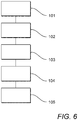
Fig. 6 is a flow diagram showing a method of forming a structural portion of the fuel tank for the aircraft ofFig. 1 . - Referring to
Fig. 1 , anaircraft 10 is shown. Theaircraft 10 has afuselage 11 andwings 12. Thewings 12 extend from thefuselage 11. Anengine 13 is mounted to eachwing 12. - Fuel for each
engine 13 is stored in one or moreaircraft fuel tanks 20. Fuel for each engine is stored in a centre tank within thefuselage 13 and one or more wing tanks within thewings 12. The description below refers to theaircraft fuel tank 20, which could equally refer to the centre tank, any of the wing tanks, or an alternative fuel tank arrangement. - Referring to
Fig. 2 , a schematic view of afuel tank 20 is shown. Thefuel tank 20 includes a number of fuel tankstructural portion 21, such as a base, outer walls and an upper side. Thefuel tank 20 defines afuel receiving space 22. The fuel tankstructural portions 21 may be formed from other structural parts of theaircraft 10, such as skins, ribs and spars. Thestructural portion 21 is a portion that contributes to the structure of the fuel tank. - In
Fig. 2 , onestructural portion 21, in this case a wall, has asensor 30. Thesensor 30 is integrated in thestructural portion 21. It will be understood that the configuration of thesensor 30 and thefuel tank 20 is shown schematically inFig. 2 and so the configuration may vary. - The
sensor 30 is isolated from thefuel receiving space 22 of thefuel tank 20. Therefore, thesensor 30 cannot come into contact with fuel received therein. Thesensor 30 is also isolated from the external environment outside the fuel tank. - The
sensor 30 is part of a fuelquantity measuring system 40. The fuelquantity measuring system 40 comprises thesensor 30 and aninterrogation system 50. The fuelquantity measuring system 40 is non-invasive. That is, none of the components of the fuelquantity measuring system 40 are exposed to thefuel receiving space 21 of thefuel tank 20. - Details of the arrangement and method of operation of the fuel
quantity measuring system 40 are disclosed in detail inUS Patent Number 7 814 786 B1, filed 17 January 2008 , the contents of which are hereby incorporated by reference. A detailed description of the fuelquantity measuring system 40 and its method of operation will only be described briefly herein. - The fuel
quantity measuring system 40 is a wireless sensing system. That is, thesensor 30 is electrically isolated from the remainder of the fuelquantity measuring system 40. Thesensor 30 is formed of anelectrical conductor 31 shaped to form a spiral arrangement. Theelectrical conductor 31 is arranged on a plane, that is in a two-dimensional geometric pattern. Theelectrical conductor 31 has an open-circuit arrangement, having inductance and capacitance. Thesensor 30 is able to store and transfer electrical and magnetic energy. The spiral arrangement of theelectrical conductor 31 is shown inFig. 2 . - The
electrical conductor 31 of thesensor 30 is formed from an electrically conductive wire. By using an electrically conductive wire, the reliability of the sensor is maximised. The method of forming thesensor 30 will be described below. - The electrically conductive wire has a uniform cross section along its length. The electrically conductive wire is arranged, upon assembly, to have uniform spacing between adjacent sections of the electrically conductive wire. Adjacent sections extend parallel to each other. However, the
sensor 30 is not limited to a uniformly spaced, spiral arrangement, and may be another geometrically shaped conductor arrangement. However, it will be understood that the specific arrangement and geometry of theelectrical conductor 31 should be predefined and maintained throughout forming of the sensor andstructural portion 21 of thefuel tank 20. - The
sensor 30 in which inductance and capacitance are operatively coupled defines a magnetic field response sensor. - The
interrogation system 50 is a magnetic field response recorder. Referring toFig. 3 , theinterrogation system 50 includes anantenna 51 and acontrol unit 52. Theantenna 51 is a broadband radio frequency (RF) antenna configured to transmit and receive RF energy. It will be understood that theantenna 52 may be a single antenna, or separate transmission and receiving antennas. - The
control unit 52 comprises a processor and a memory. Thecontrol unit 52 is configured to control theantenna 51 to transmit RF energy. Thecontrol unit 52 is also configured to determine the response received by theantenna 51. - The
sensor 30 resonates in the presence of a time-varying magnetic field to generate a harmonic response having a frequency, amplitude and bandwidth. Theinterrogation system 50, acting as a magnetic field response recorder, wirelessly transmits the time-varying magnetic field to the sensor and wirelessly detects the sensor's response frequency, amplitude and bandwidth. - The
antenna 52 is disposed proximate to thesensor 30, within range to reliably transmit and receive RF energy to thesensor 30. Theantenna 52 is disposed external to thefuel tank 30. As such, theinterrogation system 52 is more easily accessible for installation and maintenance. Theinterrogation system 52 is in spaced relationship to thesensor 30. - The
structural portion 21 of thefuel tank 20 is shown schematically inFig. 3 . Thestructural portion 21 is formed from a carbon fibre reinforced polymer, such as a carbon fibre reinforced plastic (CFRP). Thestructural portion 21 comprises carbon fibres acting as a reinforcement. The carbon fibres are arranged in a plurality of fibre plies 23. Each ply 23 is formed from a plurality of fibres arranged in a weave, although the specific arrangement may vary. InFig. 3 , two fibre plies 23 are shown, however the number of plies is not limited to two plies. Thestructural portion 21 also comprises a resin acting as a polymer matrix 27. The polymer matrix 27 covers the fibre plies and is dispersed between the fibre plies. - Although, in the present embodiment, the
structural portion 21 is formed from carbon fibre reinforced polymer, it will be understood that alternative reinforcement materials may be used. For example, an alternative fibre reinforcement material may be used. Furthermore, a combination of carbon fibres and/or alternative fibre materials may be used, for example kevlar, aluminium and fibreglass. - Although, in the present embodiment, the polymer matrix is a resin, it will be understood that materials for the polymer matric may include an epoxy, polyester, vinyl ester or nylon, or another polymerized resin.
- The
structural component 21 comprises thesensor 30. Thesensor 30 is mounted to one of the fibre plies 23. An embroideredarrangement 24, acting as a mounting arrangement, mounts thesensor 30 to thefibre ply 23. The embroideredarrangement 24 directly mounts the electrically conductive wire to thefibre ply 23. Therefore, thesensor 30 is mounted to a mountingface 25 of thefibre ply 23. - The electrically conductive wire is mounted in a fixed relationship on the mounting
face 25. The embroideredarrangement 24 comprises athread 26 which is mounted to the fibre ply 23 by tailored fibre placement. In the present embodiment, thethread 26 is a carbon or Kevlar material, although alternative materials are possible. The thread may be formed from the same material as thefibre ply 23. - The method of forming the
fuel tank 20, and in particular thestructural portion 21, will now be described with reference, in particular, toFig. 4, Fig. 5 andFig. 6 . Although a number of method steps are described below, it will be understood that in embodiments, one or more method steps may be omitted, and/or one or more method steps additionally included. It will also be understood that the order of one or more method steps may be altered. - In
step 101, thefibre ply 23, which acts as a structural component of the structural portion, is provided. - At
step 102, the electrically conductive wire is mounted to the fibre ply 23 to form thesensor 30. The electrically conductive wire is mounted in place by the embroideredarrangement 24. - The embroidered
arrangement 24 is formed by a double lock stitch technique, although the forming of the embroideredarrangement 24 is not limited thereto. The electrically conductive wire is positioned on thefibre ply 23 and fixedly mounted in a predetermined arrangement by the tailored fibre placement, in which the wire acting as the fibre is fed and held in position by a guidingelement 61 of an embroideringmachine 60. Aneedle 62 of the embroideringmachine 60 stitches thethread 26 through thefibre ply 23 and over the electrically conductive wire in a predetermined pattern. Therefore, the electrically conductive wire is mounted in situ. - Once the desired length of electrically conductive wire is mounted to the
fibre ply 23, the embroideringmachine 60 is removed. The fibre ply 23 therefore acts as a structural component. - At
step 103, the fibre ply 23 on which the electrically conductive wire is mounted is disposed in a stack of fibre plies 23. The fibre ply 23 on which the electrically conductive wire is mounted may be an outer ply, or an inner ply. If positioned as an outer ply, the mountingface 25 on which thesensor 30 is mounted may be exposed or face inwardly. In a situation when the mountingface 25 faces inwardly, or the fibre ply 23 on which the electrically conductive wire is mounted is an inner ply, then thesensor 30 is disposed between two plies. - As one of the fibre plies 23 of the ply stack forming structural components acts as the substrate for the sensor, it has been found by the inventor that it is possible to dispose the
sensor 30 in the structural portion without causing a ramped ply arrangement which would result from use of a sensor substrate, whilst enabling the sensor to be fixedly mounted in a predetermined geometric pattern. - The ply stack is disposed in a mold.
- At
step 104, the polymer matrix 27 is applied to the ply stack. The polymer matrix 27 covers the fibre plies 23 and thesensor 30. When the polymer matrix 27 has hardened, thestructural portion 21 is removed from the mold. As such, thesensor 30 is isolated from thefuel receiving space 22 and the environment external to thefuel tank 20. - At
step 105, thefuel tank 20 is assembled together with theinterrogation system 50 so that theinterrogation system 50 is in spaced relationship with thesensor 30. - Although the invention has been described above with reference to one or more preferred embodiments, it will be appreciated that various changes or modifications may be made without departing from the scope of the invention as defined in the appended claims.
Claims (15)
- A method of forming a structural portion (21) of a fuel tank (20) for an aircraft (10), the structural portion being formed from a fibre reinforced polymer and having a sensor (30) integrated in the structural portion, the method comprising:providing a fibre ply (23) acting as a structural component,embroidering an electrically conductive wire (31) in a predetermined pattern on the fibre ply to form the sensor so that the fibre ply acts as a sensor substrate, andapplying a polymer matrix (27) to the fibre ply, so that the fibre ply and electrically conductive wire are covered by the polymer matrix.
- The method according to claim 1, further comprising providing a magnetic field response sensor as the sensor (30).
- The method according to claim 1 or claim 2, further comprising covering the sensor (30) with the polymer matrix (27) so that the sensor is electrically isolated.
- The method according to any preceding claim, further comprising providing the predetermined pattern as a flat coil arrangement.
- The method according to any preceding claim, further comprising providing the predetermined pattern on a plane.
- The method according to any preceding claim, further comprising providing a structural fibre ply stack to form part of the structural portion (21), wherein the fibre ply (23) is arranged as part of the structural fibre ply stack.
- The method according to claim 6, further comprising providing the sensor (30) between the fibre ply (23) to which the sensor is embroidered and another fibre ply of the structural fibre ply stack.
- The method according to claim 6, further comprising providing the sensor (30) on an outer face of the structural fibre ply stack.
- The method according to any preceding claim, further comprising forming the fibre ply (23) from carbon fibre.
- The method according to any preceding claim, further comprising forming the polymer matrix (27) from a resin.
- The method according to any preceding claim, further comprising embroidering the electrically conductive wire (31) to the fibre ply (23) by tailored fibre placement.
- The method according to any preceding claim, further comprising providing the fibre ply (23) to extend significantly from the boundary of the sensor (30).
- A fuel tank (20) for an aircraft (10) comprising:a structural portion (21) of the fuel tank, the structural portion being formed from a fibre reinforced polymer comprising a fibre ply (23) acting as a structural component and a polymer matrix (27),a sensor (30) integrated in the structural portion, the sensor comprising an electrically conductive wire (31) embroidered to the fibre ply in a predetermined pattern in which the fibre ply acts as a sensor substrate,wherein the fibre ply and electrically conductive wire embroidered to the fibre ply are covered by the polymer matrix.
- A fuel quantity indicating system comprising a fuel tank (20) according to claim 13 and an interrogation system (50) spaced from the sensor (30) which is configured to interrogate the sensor to determine a fuel quantity in the fuel tank.
- An aircraft comprising a fuel quantity indicating system according to claim 14.
Applications Claiming Priority (1)
| Application Number | Priority Date | Filing Date | Title |
|---|---|---|---|
| GB1610934.0A GB2551560A (en) | 2016-06-22 | 2016-06-22 | A method of forming a structural portion of a fuel tank for an aircraft |
Publications (1)
| Publication Number | Publication Date |
|---|---|
| EP3260825A1 true EP3260825A1 (en) | 2017-12-27 |
Family
ID=56895002
Family Applications (1)
| Application Number | Title | Priority Date | Filing Date |
|---|---|---|---|
| EP17175369.2A Withdrawn EP3260825A1 (en) | 2016-06-22 | 2017-06-09 | A method of forming a structural portion of a fuel tank for an aircraft |
Country Status (3)
| Country | Link |
|---|---|
| US (1) | US20170368769A1 (en) |
| EP (1) | EP3260825A1 (en) |
| GB (1) | GB2551560A (en) |
Families Citing this family (6)
| Publication number | Priority date | Publication date | Assignee | Title |
|---|---|---|---|---|
| EP3210883B1 (en) * | 2016-02-29 | 2020-01-29 | Airbus Operations, S.L. | Aircraft airfoil having a stitched trailing edge and manufacturing method thereof |
| FR3062810A1 (en) * | 2017-02-13 | 2018-08-17 | Airbus Operations | METHOD AND SYSTEM FOR ZIGZAG STITCH FASTENING OF A FUNCTIONAL FLEXIBLE ELEMENT ON A FLEXIBLE SUPPORT. |
| US11559918B2 (en) | 2018-10-10 | 2023-01-24 | Rolls-Royce Corporation | Additively manufactured composite components |
| FR3104505B1 (en) * | 2019-12-16 | 2021-11-12 | Airbus Operations Sas | VEHICLE EQUIPPED WITH A HYDROGEN TANK CONTAINING AT LEAST ONE ELECTRICAL CONNECTION DEVICE |
| IL273373B (en) | 2020-03-17 | 2021-05-31 | Israel Aerospace Ind Ltd | Fuel tank |
| FR3136398B1 (en) * | 2022-06-09 | 2024-05-31 | Centre Technique Ind De La Plasturgie Et Des Composites | Preform for manufacturing a composite material part comprising a capacitive sensor, method of manufacturing such a preform, composite material part and associated manufacturing process. |
Citations (6)
| Publication number | Priority date | Publication date | Assignee | Title |
|---|---|---|---|---|
| EP1923680A2 (en) * | 2006-11-15 | 2008-05-21 | Strukturleichtbau e.V. | Method for manufacturing a signal structure |
| WO2008089302A1 (en) * | 2007-01-17 | 2008-07-24 | United States Of America As Represented By The Administrator Of The National Aeronautics And Space Administration | Wireless sensing system for non-invasive monitoring of attributes of contents in a container |
| DE202008012482U1 (en) * | 2008-09-17 | 2008-11-20 | Strukturleichtbau E.V. | level sensor |
| US20090120180A1 (en) * | 2007-11-12 | 2009-05-14 | Yung-Lieh Chien | Solution metering apparatus having temperature sensing function |
| WO2015061642A2 (en) * | 2013-10-24 | 2015-04-30 | United States Of America, As Represented By The Administrator Of The Nat'l Aeronautics & Space Adm. | Multi-layer wireless sensor construct for use at electrically-conductive material surfaces |
| EP2979977A1 (en) * | 2013-03-26 | 2016-02-03 | Mitsubishi Heavy Industries, Ltd. | Fuel tank, main wings, aircraft fuselage, aircraft, and moving body |
Family Cites Families (5)
| Publication number | Priority date | Publication date | Assignee | Title |
|---|---|---|---|---|
| US7522121B2 (en) * | 2005-05-19 | 2009-04-21 | General Electric Company | Method for fabricating an antenna |
| US8430327B2 (en) * | 2006-02-06 | 2013-04-30 | The United States Of America As Represented By The Administrator Of The National Aeronautics And Space Administration | Wireless sensing system using open-circuit, electrically-conductive spiral-trace sensor |
| US10023322B2 (en) * | 2012-01-30 | 2018-07-17 | Neal Keefer | Molded fuel tank and method of manufacturing the same |
| WO2013188443A2 (en) * | 2012-06-12 | 2013-12-19 | CAPLAN, Jeffrey, Brian | Fluid level and volume measuring systems and methods of making and using the same |
| EP3122637B1 (en) * | 2014-03-25 | 2018-10-10 | Zodiac Aerosafety Systems | Aviation fuel tank with rigid wall for crash energy absorption |
-
2016
- 2016-06-22 GB GB1610934.0A patent/GB2551560A/en not_active Withdrawn
-
2017
- 2017-06-09 EP EP17175369.2A patent/EP3260825A1/en not_active Withdrawn
- 2017-06-21 US US15/629,724 patent/US20170368769A1/en not_active Abandoned
Patent Citations (6)
| Publication number | Priority date | Publication date | Assignee | Title |
|---|---|---|---|---|
| EP1923680A2 (en) * | 2006-11-15 | 2008-05-21 | Strukturleichtbau e.V. | Method for manufacturing a signal structure |
| WO2008089302A1 (en) * | 2007-01-17 | 2008-07-24 | United States Of America As Represented By The Administrator Of The National Aeronautics And Space Administration | Wireless sensing system for non-invasive monitoring of attributes of contents in a container |
| US20090120180A1 (en) * | 2007-11-12 | 2009-05-14 | Yung-Lieh Chien | Solution metering apparatus having temperature sensing function |
| DE202008012482U1 (en) * | 2008-09-17 | 2008-11-20 | Strukturleichtbau E.V. | level sensor |
| EP2979977A1 (en) * | 2013-03-26 | 2016-02-03 | Mitsubishi Heavy Industries, Ltd. | Fuel tank, main wings, aircraft fuselage, aircraft, and moving body |
| WO2015061642A2 (en) * | 2013-10-24 | 2015-04-30 | United States Of America, As Represented By The Administrator Of The Nat'l Aeronautics & Space Adm. | Multi-layer wireless sensor construct for use at electrically-conductive material surfaces |
Non-Patent Citations (1)
| Title |
|---|
| K. L. DUDLEY ET AL.: "Damage Detection Response Characteristics of Open Circuit Resonant (SansEC) Sensors", 2013 INTERNATIONAL CONFERENCE ON LIGHTNING AND STATIC ELECTRICITY (ICOLSE), SEATTLE, USA, 18 September 2013 (2013-09-18), XP055236320 * |
Also Published As
| Publication number | Publication date |
|---|---|
| GB201610934D0 (en) | 2016-08-03 |
| US20170368769A1 (en) | 2017-12-28 |
| GB2551560A (en) | 2017-12-27 |
Similar Documents
| Publication | Publication Date | Title |
|---|---|---|
| US20170368769A1 (en) | Method of forming a structural portion of a fuel tank for an aircraft | |
| US7814786B2 (en) | Wireless sensing system for non-invasive monitoring of attributes of contents in a container | |
| US11548331B2 (en) | Pneumatic tire equipped with an electronic member | |
| US10444086B2 (en) | System and method of magnetic shielding for sensors | |
| JP7488915B2 (en) | Improved RFID sensor device with patch antenna for tires - Patents.com | |
| US10180341B2 (en) | Multi-layer wireless sensor construct for use at electrically-conductive material surfaces | |
| EP3495273B1 (en) | Lightning protection in aircrafts constructed with carbon fiber reinforced plastic | |
| CA3000887C (en) | Method for detecting arrangement disorder of fibers in conductive composite material, and device for detecting arrangement disorder of fibers in conductive composite material | |
| WO2007129569A1 (en) | Structure for attaching rfid tag and method for detecting rfid tag | |
| EP3055662B1 (en) | Device for detecting strains and transmitting detected data and method for manufacturing the same | |
| CN113678317B (en) | Radar module with microwave chip | |
| KR20200096313A (en) | Wire-wound electrical component with printed electronic sensor | |
| US20180106691A1 (en) | Device for detecting strains and transmitting detected data | |
| Woodard et al. | Measurement of multiple unrelated physical quantities using a single magnetic field response sensor | |
| US11606010B2 (en) | Electric machine comprising a device for monitoring the rotor winding head | |
| EP4610433A1 (en) | Management system and method for pneumatic fender | |
| US10272984B2 (en) | Apparatuses and methods for flexurally controlling elongated structures | |
| CN116438367A (en) | Composite parts especially for aircraft turbine engines | |
| US20250123181A1 (en) | Electromechanical actuator with operational sensors | |
| US20230314182A1 (en) | Composite cylinder | |
| US11590719B2 (en) | Method and compositions for embedding electronics in fiber-composite parts fabricated via compression molding | |
| EP3290884B1 (en) | System and method of magnetic shielding for sensors | |
| US20110174878A1 (en) | Planar sensor structure | |
| US10299392B2 (en) | Integrally bonded and installed protective enclosure |
Legal Events
| Date | Code | Title | Description |
|---|---|---|---|
| PUAI | Public reference made under article 153(3) epc to a published international application that has entered the european phase |
Free format text: ORIGINAL CODE: 0009012 |
|
| STAA | Information on the status of an ep patent application or granted ep patent |
Free format text: STATUS: THE APPLICATION HAS BEEN PUBLISHED |
|
| AK | Designated contracting states |
Kind code of ref document: A1 Designated state(s): AL AT BE BG CH CY CZ DE DK EE ES FI FR GB GR HR HU IE IS IT LI LT LU LV MC MK MT NL NO PL PT RO RS SE SI SK SM TR |
|
| AX | Request for extension of the european patent |
Extension state: BA ME |
|
| STAA | Information on the status of an ep patent application or granted ep patent |
Free format text: STATUS: REQUEST FOR EXAMINATION WAS MADE |
|
| 17P | Request for examination filed |
Effective date: 20180430 |
|
| RBV | Designated contracting states (corrected) |
Designated state(s): AL AT BE BG CH CY CZ DE DK EE ES FI FR GB GR HR HU IE IS IT LI LT LU LV MC MK MT NL NO PL PT RO RS SE SI SK SM TR |
|
| STAA | Information on the status of an ep patent application or granted ep patent |
Free format text: STATUS: EXAMINATION IS IN PROGRESS |
|
| 17Q | First examination report despatched |
Effective date: 20180926 |
|
| STAA | Information on the status of an ep patent application or granted ep patent |
Free format text: STATUS: THE APPLICATION IS DEEMED TO BE WITHDRAWN |
|
| 18D | Application deemed to be withdrawn |
Effective date: 20191203 |