EP3260750A1 - Valve assembly having a manual override unit - Google Patents
Valve assembly having a manual override unit Download PDFInfo
- Publication number
- EP3260750A1 EP3260750A1 EP17176678.5A EP17176678A EP3260750A1 EP 3260750 A1 EP3260750 A1 EP 3260750A1 EP 17176678 A EP17176678 A EP 17176678A EP 3260750 A1 EP3260750 A1 EP 3260750A1
- Authority
- EP
- European Patent Office
- Prior art keywords
- plunger
- valve
- base
- valve assembly
- disposed
- Prior art date
- Legal status (The legal status is an assumption and is not a legal conclusion. Google has not performed a legal analysis and makes no representation as to the accuracy of the status listed.)
- Granted
Links
Images

Classifications
-
- F—MECHANICAL ENGINEERING; LIGHTING; HEATING; WEAPONS; BLASTING
- F16—ENGINEERING ELEMENTS AND UNITS; GENERAL MEASURES FOR PRODUCING AND MAINTAINING EFFECTIVE FUNCTIONING OF MACHINES OR INSTALLATIONS; THERMAL INSULATION IN GENERAL
- F16K—VALVES; TAPS; COCKS; ACTUATING-FLOATS; DEVICES FOR VENTING OR AERATING
- F16K31/00—Actuating devices; Operating means; Releasing devices
- F16K31/44—Mechanical actuating means
- F16K31/60—Handles
- F16K31/602—Pivoting levers, e.g. single-sided
-
- F—MECHANICAL ENGINEERING; LIGHTING; HEATING; WEAPONS; BLASTING
- F16—ENGINEERING ELEMENTS AND UNITS; GENERAL MEASURES FOR PRODUCING AND MAINTAINING EFFECTIVE FUNCTIONING OF MACHINES OR INSTALLATIONS; THERMAL INSULATION IN GENERAL
- F16K—VALVES; TAPS; COCKS; ACTUATING-FLOATS; DEVICES FOR VENTING OR AERATING
- F16K1/00—Lift valves or globe valves, i.e. cut-off apparatus with closure members having at least a component of their opening and closing motion perpendicular to the closing faces
- F16K1/12—Lift valves or globe valves, i.e. cut-off apparatus with closure members having at least a component of their opening and closing motion perpendicular to the closing faces with streamlined valve member around which the fluid flows when the valve is opened
-
- F—MECHANICAL ENGINEERING; LIGHTING; HEATING; WEAPONS; BLASTING
- F16—ENGINEERING ELEMENTS AND UNITS; GENERAL MEASURES FOR PRODUCING AND MAINTAINING EFFECTIVE FUNCTIONING OF MACHINES OR INSTALLATIONS; THERMAL INSULATION IN GENERAL
- F16K—VALVES; TAPS; COCKS; ACTUATING-FLOATS; DEVICES FOR VENTING OR AERATING
- F16K31/00—Actuating devices; Operating means; Releasing devices
- F16K31/02—Actuating devices; Operating means; Releasing devices electric; magnetic
- F16K31/04—Actuating devices; Operating means; Releasing devices electric; magnetic using a motor
- F16K31/05—Actuating devices; Operating means; Releasing devices electric; magnetic using a motor specially adapted for operating hand-operated valves or for combined motor and hand operation
-
- F—MECHANICAL ENGINEERING; LIGHTING; HEATING; WEAPONS; BLASTING
- F16—ENGINEERING ELEMENTS AND UNITS; GENERAL MEASURES FOR PRODUCING AND MAINTAINING EFFECTIVE FUNCTIONING OF MACHINES OR INSTALLATIONS; THERMAL INSULATION IN GENERAL
- F16K—VALVES; TAPS; COCKS; ACTUATING-FLOATS; DEVICES FOR VENTING OR AERATING
- F16K31/00—Actuating devices; Operating means; Releasing devices
- F16K31/02—Actuating devices; Operating means; Releasing devices electric; magnetic
- F16K31/06—Actuating devices; Operating means; Releasing devices electric; magnetic using a magnet, e.g. diaphragm valves, cutting off by means of a liquid
- F16K31/0644—One-way valve
- F16K31/0655—Lift valves
-
- F—MECHANICAL ENGINEERING; LIGHTING; HEATING; WEAPONS; BLASTING
- F16—ENGINEERING ELEMENTS AND UNITS; GENERAL MEASURES FOR PRODUCING AND MAINTAINING EFFECTIVE FUNCTIONING OF MACHINES OR INSTALLATIONS; THERMAL INSULATION IN GENERAL
- F16K—VALVES; TAPS; COCKS; ACTUATING-FLOATS; DEVICES FOR VENTING OR AERATING
- F16K31/00—Actuating devices; Operating means; Releasing devices
- F16K31/02—Actuating devices; Operating means; Releasing devices electric; magnetic
- F16K31/06—Actuating devices; Operating means; Releasing devices electric; magnetic using a magnet, e.g. diaphragm valves, cutting off by means of a liquid
- F16K31/10—Actuating devices; Operating means; Releasing devices electric; magnetic using a magnet, e.g. diaphragm valves, cutting off by means of a liquid with additional mechanism between armature and closure member
-
- F—MECHANICAL ENGINEERING; LIGHTING; HEATING; WEAPONS; BLASTING
- F16—ENGINEERING ELEMENTS AND UNITS; GENERAL MEASURES FOR PRODUCING AND MAINTAINING EFFECTIVE FUNCTIONING OF MACHINES OR INSTALLATIONS; THERMAL INSULATION IN GENERAL
- F16K—VALVES; TAPS; COCKS; ACTUATING-FLOATS; DEVICES FOR VENTING OR AERATING
- F16K41/00—Spindle sealings
- F16K41/10—Spindle sealings with diaphragm, e.g. shaped as bellows or tube
Definitions
- Solenoid operated valves provide on/off and proportional flow controls in fluid systems.
- Linear direct acting on/off solenoids are commonly used in such solenoid operated valves.
- the linear direct acting on/off solenoid valve may include a pressure balancing design feature. Pressure balancing features may involve the use of dynamic seals with an O-ring attached to a valving element. The O-ring seal may degrade during operation of the solenoid operated valve.
- Solenoid operated valves used in environments without a fluid medium may use metal to metal seating.
- the metal to metal seating may degrade due to solid particles becoming generated by the sliding where of the solenoid during repeated cycling movements.
- a valve assembly includes a housing, an actuator, a plunger, a cover, a valve body, and a manual override unit.
- the housing has a base that defines a base opening, a first annular wall that extends from the base, and a second annular wall spaced apart from the first annular wall and extends from the base.
- the actuator is received within the housing and is disposed between the first annular wall and the second annular wall.
- the plunger is movably disposed within a plunger cavity that is defined by the base and the second annular wall.
- the cover is disposed on the housing and defines a cover opening.
- the valve body is connected to the housing.
- the valve body has an end wall that defines an outlet port, an annular wall that axially extends from the end wall and defines an inlet port, and a flange that extends from the end wall and engages the cover.
- the manual override unit is operatively connected to the plunger.
- a valve assembly includes a housing, a valve body, an actuator, a valve poppet, a stem, a pivot member, and a lever.
- the housing has a base that defines a base opening.
- the valve body is disposed on the housing and defines an inlet port and an outlet port.
- the actuator is operatively connected to a plunger that is disposed within the housing.
- the valve poppet extends from the plunger and extends into the valve body.
- the valve poppet is movable between an extended position in which the valve poppet inhibits fluid flow through the outlet port and a retracted position that permits fluid flow through the outlet port.
- the stem extends from the plunger and through the base opening.
- the stem defines a slot that is spaced apart from an end surface of the base.
- the pivot member is disposed on the base.
- the lever is pivotally connected to the pivot member and is at least partially received within the slot.
- a method includes providing a valve assembly having a housing that includes a base defining a base opening, a valve body disposed on the housing, an actuator operatively connected to a plunger disposed within the housing, and a valve poppet extending from the plunger.
- the method further includes providing a manual override unit that is operatively connected to the plunger.
- the method still further includes actuating the manual override unit to move the valve assembly from a closed position towards an open position.
- valve assembly 10 movable between a closed position and an open position is shown.
- the valve assembly 10 may be installed in a fluid pathway and is configured to selectively enable fluid flow within the fluid pathway.
- the valve assembly 10 may be a direct acting tubular solenoid shutoff valve.
- the valve assembly 10 includes a housing 20, an actuator 22, a plunger 24, a valve body 26, a spacer 28, a valve poppet 30, a bellows 32, and a manual override unit 34.
- the housing 20 is configured to receive a plurality of valve assembly components.
- the housing 20 includes a base 40, a first annular wall 42, and a second annular wall 44.
- the base 40 defines a base opening 50 and a base cavity 52 disposed substantially concentrically with the base opening 50.
- the base opening 50 that extends completely through an aft portion of the base 40.
- the base cavity 52 may be configured as a counterbore that extends from an end face 54 of the base 40 towards a seating face 56 of the base 40 along an axis 58.
- the first annular wall 42 extends from the base 40 along the axis 58.
- the first annular wall 42 forms an outer wall of the housing 20.
- the second annular wall 44 extends from the base 40 along the axis 58.
- the second annular wall 44 is disposed substantially concentrically with and is disposed radially inward from the first annular wall 42.
- the second annular wall 44 forms an inner wall of the housing 20.
- the second annular wall 44 is joined to the base 40.
- the base 40, the first annular wall 42, and the second annular wall 44 define an actuator cavity 60 and a plunger cavity 62.
- the actuator cavity 60 and the plunger cavity 62 are separated from each other by the second annular wall 44.
- the cover 46 is disposed over the actuator cavity 60.
- the cover 46 includes a first wall 70 and a second wall 72.
- the first wall 70 is disposed substantially transverse to the axis 58.
- the first wall 70 extends from the first annular wall 42 towards the second annular wall 44.
- the second wall 72 is disposed substantially parallel to the axis 58.
- the second wall 72 extends from the first wall 70 towards an end of the second annular wall 44.
- the first wall 70 is joined to the first annular wall 42 and the second wall 72 is joined to the second annular wall 44.
- the second wall 72 of the cover 46 defines a cover opening 74 that is disposed about the axis 58.
- the cover opening 74 is disposed substantially coaxially with the base opening 50 and the base cavity 52.
- the cover opening 74 is configured as an extension of the plunger cavity 62.
- the actuator cavity 60 is selectively accessed by the removal of the first annular wall 42.
- the actuator 22 is received within the actuator cavity 60 and is disposed between the base 40, the first annular wall 42, the second annular wall 44, and the cover 46.
- the actuator 22 is configured as a solenoid coil, or the like.
- the plunger 24 is received within at least one of the plunger cavity 62 and the cover opening 74.
- the plunger 24 is movably disposed within at least one of the plunger cavity 62 and the cover opening 74.
- the plunger 24 includes a plunger body 80 extending between a first plunger end 82 and a second plunger end 84 disposed opposite the first plunger end 82.
- the first plunger end 82 is disposed proximate the first wall 70 of the cover 46.
- the first plunger end 82 defines a first mounting feature 90 that extends from the first plunger end 82 through the cover opening 74.
- the second plunger end 84 defines a second mounting feature 92 that extends from the second plunger end 84 towards the first plunger end 82.
- the plunger 24 is movable between a first position and a second position in response to the selective activation of the actuator 22.
- the first position corresponds to a closed position of the valve assembly 10.
- the second position corresponds to an open position of the valve assembly 10.
- the second plunger end 84 of the plunger 24 is spaced apart from the end face 54 of the base 40 while the plunger 24 is in the first position.
- the spacing apart of the second plunger end 84 of the plunger 24 and the end face 54 of the base 40 defines an air gap, having an air gap length Lg.
- the second plunger end 84 of the plunger 24 engages the end face 54 of the base 40 while the plunger 24 is in the second position.
- the valve body 26 is connected to the first wall 70 of the cover 46 of the housing 20.
- the valve body 26 includes an end wall 100, an annular wall 102, and a flange 104.
- the end wall 100 is disposed substantially parallel to the first wall 70 of the cover 46 and the base 40.
- the end wall 100 defines an outlet port 110 that extends completely through the end wall 100.
- the outlet port 110 is disposed coaxially with the cover opening 74, the base cavity 52, and the base opening 50.
- the annular wall 102 extends from the end wall 100 towards the flange 104 and the housing 20.
- the annular wall 102 is disposed about the axis 58.
- the annular wall 102 defines an inlet port 112.
- the end wall 100 and annular wall 102 define a valve cavity 114.
- the valve cavity 114 fluidly connects the outlet port 110 and the inlet port 112.
- the flange 104 extends radially from an end of the annular wall 102.
- the flange 104 is configured to engage the first wall 70 of the cover 46 of the housing 20.
- the flange 104 defines a groove 120 configured to receive a sealing member such as an O-ring.
- a notch 122 is defined between the intersection of the annular wall 102 and the flanged 104.
- the spacer 28 is disposed between the cover 46 of the housing 20 and the valve body 26.
- the spacer 28 includes a first portion 130 and a second portion 132 extending from the first portion 130.
- the first portion 130 is at least partially received within the notch 122.
- the first portion 130 includes a first face 134 that engages a portion of the annular wall 102 of the valve body 26 disposed proximate the notch 122 and a second face 136 that engages the first wall 70 of the cover 46.
- the second portion 132 extends from the first portion 130 and is at least partially received within the cover opening 74.
- the second portion 132 define an annular groove 138 configured to receive a sealing member such as an O-ring that engages the second wall 72 of the cover 46 of the housing 20.
- the spacer 28 defines a spacer opening 140 and a spacer cavity 142.
- the spacer opening 140 extends at least partially through the first portion 130 of the spacer 28.
- the spacer opening 140 is disposed substantially coaxially with the outlet port 110, the spacer cavity 142, the base opening 50, and the base cavity 52.
- the spacer cavity 142 is configured as a counterbore of the spacer opening 140.
- the spacer cavity 142, the spacer opening 140, the cover opening 74, the base cavity 52, and the base opening 50 are proximately aligned along the axis 58.
- the valve poppet 30 is movable between an extended position and a retracted position.
- the extended position corresponds to the first position of the plunger 24 and the closed position of the valve assembly 10.
- the valve poppet 30 includes a valve head 150 and a valve stem 152.
- the valve head 150 of the valve poppet 30 is seated against a valve seat of the outlet port 110 of the end wall 100 of the valve body 26 to inhibit fluid flow through the outlet port 110.
- the retracted position corresponds to the second position of the plunger 24 and the open position of the valve assembly 10.
- the valve head 150 of the valve poppet 30 is spaced apart from the valve seat of the outlet port 110 of the end wall 100 of the valve body 26 to facilitate or permit fluid flow from the inlet port 112, through the valve cavity 114, and out of the outlet port 110.
- the valve stem 152 extends from the valve head 150 and is operatively connected to the first plunger end 82 of the plunger body 80 of the plunger 24.
- the valve stem 152 extends through the spacer opening 140 and the spacer cavity 142 and is received within the first mounting feature 90.
- the valve stem 152 is force fit into the first mounting feature 90 or secured within the first mounting feature 90 by a shear pin that extends through the first mounting feature 90 and the valve stem 152.
- the bellows 32 is connected to the valve head 150 of the valve poppet 30 and the spacer 28.
- the bellows 32 is joined to an end of the valve head 150 of the valve poppet 30 and the first face 134 of the first portion 130 of the spacer 28.
- the bellows 32 is configured to function as a dynamic hermetic seal to isolate the plunger cavity 62 from the working fluid that may pass through the inlet port 112 and the outlet port 110 of the valve body 26.
- the bellows 32 is a metallic bellow having an effective area substantially similar to the valve head 150 seating area to balance the fluid pressure at various operating pressures of the valve assembly 10.
- a biasing member 160 is provided.
- the biasing member 160 is received within the base cavity 52.
- the biasing member 160 is configured to engage the seating face 56 of the base 40 and the second plunger end 84 of the plunger 24 to bias the plunger 24 towards the first position, to bias the valve poppet 30 towards the extended position, and thus to bias the valve assembly 10 towards the closed position.
- the actuator 22 is selectively energized to move the plunger 24 between the first position and the second position to move the valve assembly 10 between the closed and open positions.
- the valve assembly 10 may be manually moved between the closed position and the open position by use of the manual override unit 34.
- the manual override unit 34 includes a stem 170 that is operatively connected to the plunger 24.
- the stem 170 is operatively connected to the second plunger end 84 and is received within the second mounting feature 92.
- the stem 170 may be pinned or force fit into the second mounting feature 92.
- the stem 170 extends through the base cavity 52 and the base opening 50.
- a sliding seal is disposed about the stem 170 within the base opening 50 to maintain the hermetic seal within the plunger cavity 62.
- the biasing member 160 is disposed about the stem 170.
- the stem 170 defines a slot 172.
- the slot 172 is spaced apart from an end surface of the base 40 that is disposed opposite the seating face 56.
- the stem 170 may be actuated to move the valve assembly 10 between the closed position and the open position by the application of a linear force along the axis 58 to an end of the stem 170.
- a cable 180 may be operatively connected to an end of the stem 170.
- the cable 180 may be a push pull cable that is configured to pull the stem 170 to move the plunger 24 between the first position and the second position.
- the stem 170 may be actuated by a lever assembly 190 to move the valve assembly 10 between the closed position and the open position.
- the lever assembly 190 includes a pivot member 192, a lever 194, and a collar 196.
- the pivot member 192 is disposed on the end surface of the base 40.
- the lever 194 is pivotally connected to the pivot member 192.
- the lever 194 includes a first lever end 200 that is at least partially received within the slot 172 and a second lever end 202.
- the first lever end 200 and the second lever end 202 of the lever 194 are disposed transverse to the axis 58.
- the slot 172 has a slot length, Xu, that defines a gap between a portion of the first lever end 200.
- the gap, Xu is larger than the air gap length, Lg, when the plunger 24 is in the first position.
- the lever 194 is pivotally connected to the pivot member 192 at a point disposed between the first lever end 200 and the second lever end 202.
- a torsion spring 204 is disposed about a pin that extends through the pivot member 192.
- the collar 196 is disposed on the second lever end 202.
- the application of an input force onto the collar 196 pivots the lever 194 about a pivot point defined by the pivot member 192 and the lever 194 engages an end of the slot 172 of the stem 170 to move the plunger 24 between the first position and the second position to move the valve poppet 30 between the extended position and the retracted position to move the valve assembly 10 between the closed position and the open position.
- the cable 180 is connected to a portion of the lever 194. The pulling of the cable 180 along the axis 58 pivots the lever 194 to move the plunger 24 between the first position and the second position to move the valve poppet 30 between the extended position and the retracted position to move the valve assembly 10 between the closed position and the open position.
- a cover 210 is disposed over the lever assembly 190.
- the cover 210 defines an opening 212 that at least a portion of the lever 194 and the collar 196 extends through.
- the cover 210 defines a second opening 214 through which the cable 180 extends. The cover 210 protects the lever assembly 190 of the mechanical override unit 34 from external contaminants.
Landscapes
- Engineering & Computer Science (AREA)
- General Engineering & Computer Science (AREA)
- Mechanical Engineering (AREA)
- Physics & Mathematics (AREA)
- Fluid Mechanics (AREA)
- Lift Valve (AREA)
- Magnetically Actuated Valves (AREA)
Abstract
Description
- Solenoid operated valves provide on/off and proportional flow controls in fluid systems. Linear direct acting on/off solenoids are commonly used in such solenoid operated valves. The linear direct acting on/off solenoid valve may include a pressure balancing design feature. Pressure balancing features may involve the use of dynamic seals with an O-ring attached to a valving element. The O-ring seal may degrade during operation of the solenoid operated valve.
- Solenoid operated valves used in environments without a fluid medium may use metal to metal seating. The metal to metal seating may degrade due to solid particles becoming generated by the sliding where of the solenoid during repeated cycling movements.
- Accordingly it is desirable to provide a more robust solenoid operated valve.
- According to an embodiment of the present disclosure, a valve assembly is provided. The valve assembly includes a housing, an actuator, a plunger, a cover, a valve body, and a manual override unit. The housing has a base that defines a base opening, a first annular wall that extends from the base, and a second annular wall spaced apart from the first annular wall and extends from the base. The actuator is received within the housing and is disposed between the first annular wall and the second annular wall. The plunger is movably disposed within a plunger cavity that is defined by the base and the second annular wall. The cover is disposed on the housing and defines a cover opening. The valve body is connected to the housing. The valve body has an end wall that defines an outlet port, an annular wall that axially extends from the end wall and defines an inlet port, and a flange that extends from the end wall and engages the cover. The manual override unit is operatively connected to the plunger.
- According to another embodiment of the present disclosure, a valve assembly is provided. The valve assembly includes a housing, a valve body, an actuator, a valve poppet, a stem, a pivot member, and a lever. The housing has a base that defines a base opening. The valve body is disposed on the housing and defines an inlet port and an outlet port. The actuator is operatively connected to a plunger that is disposed within the housing. The valve poppet extends from the plunger and extends into the valve body. The valve poppet is movable between an extended position in which the valve poppet inhibits fluid flow through the outlet port and a retracted position that permits fluid flow through the outlet port. The stem extends from the plunger and through the base opening. The stem defines a slot that is spaced apart from an end surface of the base. The pivot member is disposed on the base. The lever is pivotally connected to the pivot member and is at least partially received within the slot.
- According to yet another embodiment of the present disclosure, a method is provided. The method includes providing a valve assembly having a housing that includes a base defining a base opening, a valve body disposed on the housing, an actuator operatively connected to a plunger disposed within the housing, and a valve poppet extending from the plunger. The method further includes providing a manual override unit that is operatively connected to the plunger. The method still further includes actuating the manual override unit to move the valve assembly from a closed position towards an open position.
- The subject matter which is regarded as the present disclosure is particularly pointed out and distinctly claimed in the claims at the conclusion of the specification. The foregoing and other features, and advantages of the present disclosure are apparent from the following detailed description taken in conjunction with the accompanying drawings in which:
-
FIG. 1 is a partial cross-sectional view of a valve assembly in a closed position; and -
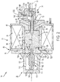
FIG. 2 is a partial cross-sectional view of the valve assembly in an open position. - Referring now to the Figures, where the present disclosure will be described with reference to specific embodiments, without limiting same, it is to be understood that the disclosed embodiments are merely illustrative and may be embodied in various and alternative forms. The Figures are not necessarily to scale; some features may be exaggerated or minimized to show details of particular components. Therefore, specific structural and functional details disclosed herein are not to be interpreted as limiting, but merely as a representative basis for teaching one skilled in the art to variously employ the present disclosure.
- Referring to
FIGS. 1 and2 , a cross-sectional view of avalve assembly 10 movable between a closed position and an open position is shown. Thevalve assembly 10 may be installed in a fluid pathway and is configured to selectively enable fluid flow within the fluid pathway. Thevalve assembly 10 may be a direct acting tubular solenoid shutoff valve. Thevalve assembly 10 includes ahousing 20, anactuator 22, aplunger 24, avalve body 26, aspacer 28, a valve poppet 30, abellows 32, and amanual override unit 34. - The
housing 20 is configured to receive a plurality of valve assembly components. Thehousing 20 includes abase 40, a firstannular wall 42, and a secondannular wall 44. Thebase 40 defines abase opening 50 and abase cavity 52 disposed substantially concentrically with thebase opening 50. The base opening 50 that extends completely through an aft portion of thebase 40. Thebase cavity 52 may be configured as a counterbore that extends from anend face 54 of thebase 40 towards aseating face 56 of thebase 40 along anaxis 58. - The first
annular wall 42 extends from thebase 40 along theaxis 58. The firstannular wall 42 forms an outer wall of thehousing 20. The secondannular wall 44 extends from thebase 40 along theaxis 58. The secondannular wall 44 is disposed substantially concentrically with and is disposed radially inward from the firstannular wall 42. The secondannular wall 44 forms an inner wall of thehousing 20. The secondannular wall 44 is joined to thebase 40. - The
base 40, the firstannular wall 42, and the secondannular wall 44 define anactuator cavity 60 and aplunger cavity 62. Theactuator cavity 60 and theplunger cavity 62 are separated from each other by the secondannular wall 44. - The
cover 46 is disposed over theactuator cavity 60. Thecover 46 includes afirst wall 70 and asecond wall 72. Thefirst wall 70 is disposed substantially transverse to theaxis 58. Thefirst wall 70 extends from the firstannular wall 42 towards the secondannular wall 44. Thesecond wall 72 is disposed substantially parallel to theaxis 58. Thesecond wall 72 extends from thefirst wall 70 towards an end of the secondannular wall 44. In at least one embodiment, thefirst wall 70 is joined to the firstannular wall 42 and thesecond wall 72 is joined to the secondannular wall 44. - The
second wall 72 of thecover 46 defines acover opening 74 that is disposed about theaxis 58. Thecover opening 74 is disposed substantially coaxially with thebase opening 50 and thebase cavity 52. Thecover opening 74 is configured as an extension of theplunger cavity 62. - The
actuator cavity 60 is selectively accessed by the removal of the firstannular wall 42. Theactuator 22 is received within theactuator cavity 60 and is disposed between the base 40, the firstannular wall 42, the secondannular wall 44, and thecover 46. Theactuator 22 is configured as a solenoid coil, or the like. - The
plunger 24 is received within at least one of theplunger cavity 62 and thecover opening 74. Theplunger 24 is movably disposed within at least one of theplunger cavity 62 and thecover opening 74. Theplunger 24 includes aplunger body 80 extending between afirst plunger end 82 and asecond plunger end 84 disposed opposite thefirst plunger end 82. - The
first plunger end 82 is disposed proximate thefirst wall 70 of thecover 46. Thefirst plunger end 82 defines a first mountingfeature 90 that extends from thefirst plunger end 82 through thecover opening 74. Thesecond plunger end 84 defines asecond mounting feature 92 that extends from thesecond plunger end 84 towards thefirst plunger end 82. - The
plunger 24 is movable between a first position and a second position in response to the selective activation of theactuator 22. The first position corresponds to a closed position of thevalve assembly 10. The second position corresponds to an open position of thevalve assembly 10. - The
second plunger end 84 of theplunger 24 is spaced apart from theend face 54 of the base 40 while theplunger 24 is in the first position. The spacing apart of thesecond plunger end 84 of theplunger 24 and theend face 54 of thebase 40 defines an air gap, having an air gap length Lg. Thesecond plunger end 84 of theplunger 24 engages theend face 54 of the base 40 while theplunger 24 is in the second position. - The
valve body 26 is connected to thefirst wall 70 of thecover 46 of thehousing 20. Thevalve body 26 includes anend wall 100, anannular wall 102, and aflange 104. Theend wall 100 is disposed substantially parallel to thefirst wall 70 of thecover 46 and thebase 40. Theend wall 100 defines anoutlet port 110 that extends completely through theend wall 100. Theoutlet port 110 is disposed coaxially with thecover opening 74, thebase cavity 52, and thebase opening 50. - The
annular wall 102 extends from theend wall 100 towards theflange 104 and thehousing 20. Theannular wall 102 is disposed about theaxis 58. Theannular wall 102 defines aninlet port 112. Theend wall 100 andannular wall 102 define avalve cavity 114. Thevalve cavity 114 fluidly connects theoutlet port 110 and theinlet port 112. - The
flange 104 extends radially from an end of theannular wall 102. Theflange 104 is configured to engage thefirst wall 70 of thecover 46 of thehousing 20. Theflange 104 defines agroove 120 configured to receive a sealing member such as an O-ring. Anotch 122 is defined between the intersection of theannular wall 102 and the flanged 104. - The
spacer 28 is disposed between thecover 46 of thehousing 20 and thevalve body 26. Thespacer 28 includes afirst portion 130 and asecond portion 132 extending from thefirst portion 130. Thefirst portion 130 is at least partially received within thenotch 122. Thefirst portion 130 includes afirst face 134 that engages a portion of theannular wall 102 of thevalve body 26 disposed proximate thenotch 122 and asecond face 136 that engages thefirst wall 70 of thecover 46. - The
second portion 132 extends from thefirst portion 130 and is at least partially received within thecover opening 74. Thesecond portion 132 define anannular groove 138 configured to receive a sealing member such as an O-ring that engages thesecond wall 72 of thecover 46 of thehousing 20. - The
spacer 28 defines aspacer opening 140 and aspacer cavity 142. Thespacer opening 140 extends at least partially through thefirst portion 130 of thespacer 28. Thespacer opening 140 is disposed substantially coaxially with theoutlet port 110, thespacer cavity 142, thebase opening 50, and thebase cavity 52. Thespacer cavity 142 is configured as a counterbore of thespacer opening 140. Thespacer cavity 142, thespacer opening 140, thecover opening 74, thebase cavity 52, and thebase opening 50 are proximately aligned along theaxis 58. - The
valve poppet 30 is movable between an extended position and a retracted position. The extended position corresponds to the first position of theplunger 24 and the closed position of thevalve assembly 10. Thevalve poppet 30 includes avalve head 150 and avalve stem 152. Thevalve head 150 of thevalve poppet 30 is seated against a valve seat of theoutlet port 110 of theend wall 100 of thevalve body 26 to inhibit fluid flow through theoutlet port 110. The retracted position corresponds to the second position of theplunger 24 and the open position of thevalve assembly 10. Thevalve head 150 of thevalve poppet 30 is spaced apart from the valve seat of theoutlet port 110 of theend wall 100 of thevalve body 26 to facilitate or permit fluid flow from theinlet port 112, through thevalve cavity 114, and out of theoutlet port 110. - The
valve stem 152 extends from thevalve head 150 and is operatively connected to thefirst plunger end 82 of theplunger body 80 of theplunger 24. Thevalve stem 152 extends through thespacer opening 140 and thespacer cavity 142 and is received within the first mountingfeature 90. Thevalve stem 152 is force fit into the first mountingfeature 90 or secured within the first mountingfeature 90 by a shear pin that extends through the first mountingfeature 90 and thevalve stem 152. - The bellows 32 is connected to the
valve head 150 of thevalve poppet 30 and thespacer 28. The bellows 32 is joined to an end of thevalve head 150 of thevalve poppet 30 and thefirst face 134 of thefirst portion 130 of thespacer 28. The bellows 32 is configured to function as a dynamic hermetic seal to isolate theplunger cavity 62 from the working fluid that may pass through theinlet port 112 and theoutlet port 110 of thevalve body 26. The bellows 32 is a metallic bellow having an effective area substantially similar to thevalve head 150 seating area to balance the fluid pressure at various operating pressures of thevalve assembly 10. - In at least one embodiment, a biasing
member 160 is provided. The biasingmember 160 is received within thebase cavity 52. The biasingmember 160 is configured to engage theseating face 56 of thebase 40 and thesecond plunger end 84 of theplunger 24 to bias theplunger 24 towards the first position, to bias thevalve poppet 30 towards the extended position, and thus to bias thevalve assembly 10 towards the closed position. During operation of thevalve assembly 10, theactuator 22 is selectively energized to move theplunger 24 between the first position and the second position to move thevalve assembly 10 between the closed and open positions. Thevalve assembly 10 may be manually moved between the closed position and the open position by use of themanual override unit 34. - The
manual override unit 34 includes astem 170 that is operatively connected to theplunger 24. Thestem 170 is operatively connected to thesecond plunger end 84 and is received within the second mountingfeature 92. Thestem 170 may be pinned or force fit into the second mountingfeature 92. Thestem 170 extends through thebase cavity 52 and thebase opening 50. In at least one embodiment, a sliding seal is disposed about thestem 170 within thebase opening 50 to maintain the hermetic seal within theplunger cavity 62. The biasingmember 160 is disposed about thestem 170. - The
stem 170 defines aslot 172. Theslot 172 is spaced apart from an end surface of the base 40 that is disposed opposite theseating face 56. - The
stem 170 may be actuated to move thevalve assembly 10 between the closed position and the open position by the application of a linear force along theaxis 58 to an end of thestem 170. Acable 180 may be operatively connected to an end of thestem 170. Thecable 180 may be a push pull cable that is configured to pull thestem 170 to move theplunger 24 between the first position and the second position. - The
stem 170 may be actuated by alever assembly 190 to move thevalve assembly 10 between the closed position and the open position. Thelever assembly 190 includes apivot member 192, alever 194, and acollar 196. Thepivot member 192 is disposed on the end surface of thebase 40. - The
lever 194 is pivotally connected to thepivot member 192. Thelever 194 includes afirst lever end 200 that is at least partially received within theslot 172 and asecond lever end 202. Thefirst lever end 200 and thesecond lever end 202 of thelever 194 are disposed transverse to theaxis 58. Theslot 172 has a slot length, Xu, that defines a gap between a portion of thefirst lever end 200. The gap, Xu, is larger than the air gap length, Lg, when theplunger 24 is in the first position. Thelever 194 is pivotally connected to thepivot member 192 at a point disposed between thefirst lever end 200 and thesecond lever end 202. In at least one embodiment, atorsion spring 204 is disposed about a pin that extends through thepivot member 192. - The
collar 196 is disposed on thesecond lever end 202. The application of an input force onto thecollar 196 pivots thelever 194 about a pivot point defined by thepivot member 192 and thelever 194 engages an end of theslot 172 of thestem 170 to move theplunger 24 between the first position and the second position to move thevalve poppet 30 between the extended position and the retracted position to move thevalve assembly 10 between the closed position and the open position. - In at least one embodiment, the
cable 180 is connected to a portion of thelever 194. The pulling of thecable 180 along theaxis 58 pivots thelever 194 to move theplunger 24 between the first position and the second position to move thevalve poppet 30 between the extended position and the retracted position to move thevalve assembly 10 between the closed position and the open position. - In at least one embodiment, a
cover 210 is disposed over thelever assembly 190. Thecover 210 defines anopening 212 that at least a portion of thelever 194 and thecollar 196 extends through. In other embodiments, thecover 210 defines asecond opening 214 through which thecable 180 extends. Thecover 210 protects thelever assembly 190 of themechanical override unit 34 from external contaminants. - While the present disclosure has been described in detail in connection with only a limited number of embodiments, it should be readily understood that the present disclosure is not limited to such disclosed embodiments. Rather, the present disclosure can be modified to incorporate any number of variations, alterations or substitutions not heretofore described, but which are commensurate with the spirit and scope of the present disclosure. Additionally, while various embodiments of the present disclosure have been described, it is to be understood that aspects of the present disclosure may include only some of the described embodiments. Accordingly, the present disclosure is not to be seen as limited by the foregoing description, but is only limited by the scope of the appended claims.
Claims (13)
- A valve assembly (10), comprising:a housing (20) having a base (40) defining a base opening (50), a first annular wall (42) extending from the base (40), and a second annular wall (44) spaced apart from the first annular wall (42) and extending from the base (40);an actuator (22) received within the housing (20) and is disposed between the first annular wall (42) and the second annular wall (44);a plunger (24) movably disposed within a plunger cavity (62) defined by the base (40) and the second annular wall (44);a cover (46) disposed on the housing (20), the cover (46) defining a cover opening (74);a valve body (26) connected to the housing (20), the valve body (26) having an end wall (100) defining an outlet port (110), an annular wall (102) axially extending from the end wall (100) defining an inlet port (112), and a flange (104) radially extending from the end wall (100) and engages the cover (46); anda manual override unit (34) operatively connected to the plunger (24).
- The valve assembly of claim 1, further comprising:a spacer (28) that engages the valve body (26) and the cover (46), the spacer (28) defining a spacer opening (40).
- The valve assembly of claim 2, further comprising:a valve poppet (30) having a valve head (150) and a valve stem (152) that is operatively connected to a first end of the plunger (24), wherein the valve stem (152) extends through the cover opening (74) and the spacer opening (140).
- The valve assembly of claim 3, wherein the base opening (50), the cover opening (74), the outlet port (110), the spacer opening (140) are proximately aligned along an axis.
- The valve assembly of claim 3, wherein the plunger (24) is movable between a first position in which the valve head (150) engages a valve seat defined proximate the outlet port (110) and a second position in which the valve head (150) is spaced apart from the valve seat in response to selective activation of the actuator (22).
- The valve assembly of claim 5, further comprising a bellows (32) connected to the valve head (150) and a first face of the spacer (28).
- The valve assembly of claim 6, wherein the bellows (32) has an effective area that is substantially similar to a seating area of the valve head (150).
- The valve assembly of claim 6, wherein while the plunger (24) is in the first position an air gap is defined between a second end of the plunger and an end face of the base (40).
- The valve assembly of claim 8, wherein the manual override unit (34) that includes:a stem (170) operatively connected to a second end of the plunger (24), wherein the stem (170) extends through the base opening (50) and defines a slot (172); anda lever (194) pivotally connected to the base (40) and at least partially received within the slot (172).
- The valve assembly of claim 9, wherein the base (40) defines a base cavity (52) disposed concentrically with the base opening (50), configured to receive a biasing member that is disposed about the stem (170) and is configured to bias the plunger (24) towards the first position.
- The valve assembly of claim 10, wherein an air gap length is less than a slot length.
- A method, comprising:providing a valve assembly having a housing that includes a base defining a base opening, a valve body disposed on the housing, an actuator operatively connected to a plunger disposed within the housing, and a valve poppet extending from the plunger;providing a manual override unit operatively connected to the plunger; andactuating the manual override unit to move the valve assembly from a closed position towards an open position.
- The method of claim 12, wherein actuating the manual override unit includes:pivoting a lever about a pivot member disposed on the base to engage an end of a slot defined by a stem that extends from the plunger to move the valve assembly from the closed position towards the open position.
Applications Claiming Priority (1)
| Application Number | Priority Date | Filing Date | Title |
|---|---|---|---|
| IN201641021601 | 2016-06-23 |
Publications (2)
| Publication Number | Publication Date |
|---|---|
| EP3260750A1 true EP3260750A1 (en) | 2017-12-27 |
| EP3260750B1 EP3260750B1 (en) | 2025-04-02 |
Family
ID=59077969
Family Applications (1)
| Application Number | Title | Priority Date | Filing Date |
|---|---|---|---|
| EP17176678.5A Active EP3260750B1 (en) | 2016-06-23 | 2017-06-19 | Valve assembly having a manual override unit |
Country Status (2)
| Country | Link |
|---|---|
| US (1) | US10240684B2 (en) |
| EP (1) | EP3260750B1 (en) |
Families Citing this family (2)
| Publication number | Priority date | Publication date | Assignee | Title |
|---|---|---|---|---|
| EP3839307A1 (en) * | 2019-12-20 | 2021-06-23 | Dana Motion Systems Italia S.R.L. | Valve override assembly, valve, and method |
| US11655912B2 (en) * | 2021-01-14 | 2023-05-23 | Hitachi Metals, Ltd. | Bellows diaphragm assembly |
Citations (9)
| Publication number | Priority date | Publication date | Assignee | Title |
|---|---|---|---|---|
| US2269016A (en) * | 1939-11-13 | 1942-01-06 | Honeywell Regulator Co | Magnetic valve |
| FR1257143A (en) * | 1960-02-17 | 1961-03-31 | Regulation Automatique | Solenoid valve |
| US3351093A (en) * | 1963-12-27 | 1967-11-07 | White Sales Corp Graham | Manually operable solenoid valve |
| US3429340A (en) * | 1966-05-07 | 1969-02-25 | Westinghouse Bremsen Apparate | Solenoid operated valve with manual override |
| DE7632984U1 (en) * | 1976-10-21 | 1977-02-03 | Herion-Werke Kg, 7012 Fellbach | VALVE |
| US4544128A (en) * | 1983-02-24 | 1985-10-01 | Imperial Clevite Inc. | Cartridge solenoid valve with manual override |
| US4941504A (en) * | 1987-09-30 | 1990-07-17 | Jacques Beauvir | Manual fluid-control valve with limited closing pressure |
| US6740827B1 (en) * | 2002-11-27 | 2004-05-25 | Target Rock Division Of Curtis-Wright Flow Control Corporation | Bi-directional piloted solenoid-operated valve |
| US20060043324A1 (en) * | 2004-08-26 | 2006-03-02 | Saint Gobain Performance Plastics Corporation | Valve with lock-out mechanism and method of using the same |
Family Cites Families (48)
| Publication number | Priority date | Publication date | Assignee | Title |
|---|---|---|---|---|
| US1406333A (en) * | 1914-09-08 | 1922-02-14 | Westinghouse Electric & Mfg Co | Control apparatus |
| US1786234A (en) * | 1927-09-24 | 1930-12-23 | Nat Pneumatic Co | Magnet-valve construction |
| US2051938A (en) * | 1935-06-29 | 1936-08-25 | Oscar F Carlson Company | Valve assembly |
| US2239774A (en) * | 1939-06-05 | 1941-04-29 | Alva G Blanchard | Fuel cutoff means |
| US2550148A (en) * | 1944-10-06 | 1951-04-24 | Le Maire Tool & Mfg Company | Multiple position spool valve for machine tools |
| DE1632984U (en) | 1951-01-23 | 1951-12-27 | Julius Kleinschmidt | WATER VEHICLE. |
| US2757688A (en) * | 1953-08-04 | 1956-08-07 | Karl A Klingler | Two-way valve |
| US3098635A (en) * | 1960-03-14 | 1963-07-23 | Delaporte Louis Adolphe | Electromagnetic valves |
| GB1590581A (en) * | 1976-10-14 | 1981-06-03 | Hawker Siddeley Dynamics Eng | Electro-hydraulic systems |
| JPS608223Y2 (en) * | 1979-08-31 | 1985-03-22 | 黒田精工株式会社 | Manual switching device for solenoid valve |
| US4327892A (en) * | 1980-09-08 | 1982-05-04 | Autoclave Engineers, Inc. | Normally magnetically actuated valve with novel nonmagnetic override |
| DE3329734A1 (en) * | 1983-08-17 | 1985-03-07 | Mannesmann Rexroth GmbH, 8770 Lohr | PROPORTIONAL MAGNET |
| US4603832A (en) * | 1985-06-07 | 1986-08-05 | Evolutionary Concepts, Inc. | Solenoid actuator with bleed screw |
| JP3152947B2 (en) | 1991-02-15 | 2001-04-03 | 日本パルスモーター株式会社 | Airtight direct acting valve |
| US5358213A (en) * | 1993-03-31 | 1994-10-25 | Pilolla Joseph J | Faucet having automatic and manual control capability |
| US5513832A (en) * | 1994-04-22 | 1996-05-07 | Lectron Products, Inc. | Variable force solenoid valve |
| US5529281A (en) * | 1994-08-24 | 1996-06-25 | The United States Of America As Represented By The Administrator Of National Aeronautics And Space | Dual-latching solenoid-actuated valve assembly |
| US5558311A (en) * | 1994-12-08 | 1996-09-24 | Borg-Warner Automotive, Inc. | Solenoid valve harness |
| JP3531334B2 (en) * | 1995-05-23 | 2004-05-31 | 株式会社デンソー | Solenoid valve for fluid control |
| US5641148A (en) * | 1996-01-11 | 1997-06-24 | Sturman Industries | Solenoid operated pressure balanced valve |
| JP3719566B2 (en) * | 1996-05-27 | 2005-11-24 | 株式会社デンソー | solenoid valve |
| JPH09317927A (en) * | 1996-05-30 | 1997-12-12 | Mitsubishi Electric Corp | Air control valve |
| JPH10169829A (en) | 1996-12-12 | 1998-06-26 | Ckd Corp | Manual reset type solenoid valve |
| JP3784134B2 (en) * | 1997-05-14 | 2006-06-07 | 株式会社豊田自動織機 | Control valve |
| US5918635A (en) * | 1997-10-08 | 1999-07-06 | Vickers, Incorporated | Low pressure solenoid valve |
| US6182684B1 (en) | 1998-03-19 | 2001-02-06 | Robertshaw Controls Company | Bellows balanced valve |
| ATE244374T1 (en) * | 1998-12-01 | 2003-07-15 | Rausch & Pausch | DIRECTLY CONTROLLED SOLENOID VALVE |
| US6182646B1 (en) * | 1999-03-11 | 2001-02-06 | Borgwarner Inc. | Electromechanically actuated solenoid exhaust gas recirculation valve |
| US6352240B1 (en) * | 1999-05-13 | 2002-03-05 | Hill-Rom Services, Inc. | Hydraulic control apparatus for a hospital bed |
| FR2801720B1 (en) * | 1999-11-25 | 2002-01-18 | Parker Hannifin Rak Sa | MANUAL PUSH-BUTTON VALVE |
| US6581904B2 (en) * | 2000-02-16 | 2003-06-24 | Denso Corporation | Solenoid valve |
| JP4667609B2 (en) * | 2000-02-29 | 2011-04-13 | イーグル工業株式会社 | solenoid |
| JP2002130511A (en) * | 2000-10-26 | 2002-05-09 | Aisin Seiki Co Ltd | Solenoid valve |
| JP2003083464A (en) * | 2001-09-10 | 2003-03-19 | Mitsubishi Electric Corp | solenoid valve |
| US6681790B2 (en) * | 2001-10-03 | 2004-01-27 | Itt Manufacturing Enterprises, Inc. | Ported slide gate valve with gate motion to break scale build up |
| JP4316955B2 (en) * | 2003-08-11 | 2009-08-19 | イーグル工業株式会社 | Capacity control valve |
| JP4203906B2 (en) * | 2004-03-31 | 2009-01-07 | 株式会社デンソー | Solenoid valve and evaporative fuel processing system using the same |
| JP4366297B2 (en) * | 2004-11-30 | 2009-11-18 | 株式会社ケーヒン | Solenoid valve for fuel cell |
| US7414502B2 (en) * | 2005-02-14 | 2008-08-19 | Delta Power Company | Harsh environment coil-actuator for a cartridge type valve |
| JP2006258135A (en) * | 2005-03-15 | 2006-09-28 | Denso Corp | solenoid valve |
| CN101365903B (en) * | 2006-03-29 | 2010-10-13 | 伊格尔工业股份有限公司 | Control valve and control valve for variable displacement compressor using the same |
| US8066256B2 (en) | 2008-02-01 | 2011-11-29 | Danfoss A/S | Valve actuator assembly |
| US20090272924A1 (en) * | 2008-05-01 | 2009-11-05 | Honeywell International Inc. | Self-aligning poppet valve assembly |
| US20100019179A1 (en) * | 2008-07-24 | 2010-01-28 | Robertshaw Controls Company | Solenoid for a Pilot Operated Water Valve Having Reduced Copper and Increased Thermal Efficiency |
| DE102009002836A1 (en) | 2009-05-06 | 2010-11-11 | Robert Bosch Gmbh | gas valve |
| KR101167505B1 (en) * | 2011-11-01 | 2012-07-23 | 주식회사 유니크 | Oil pump control valve |
| US9016663B2 (en) * | 2012-02-22 | 2015-04-28 | Delphi Technologies, Inc. | Solenoid-actuated pressure control valve |
| US9423046B2 (en) * | 2012-02-28 | 2016-08-23 | Eaton Corporation | Flux collector with interconnected portions and method of manufacturing solenoid valve assembly having same |
-
2016
- 2016-12-07 US US15/371,406 patent/US10240684B2/en active Active
-
2017
- 2017-06-19 EP EP17176678.5A patent/EP3260750B1/en active Active
Patent Citations (9)
| Publication number | Priority date | Publication date | Assignee | Title |
|---|---|---|---|---|
| US2269016A (en) * | 1939-11-13 | 1942-01-06 | Honeywell Regulator Co | Magnetic valve |
| FR1257143A (en) * | 1960-02-17 | 1961-03-31 | Regulation Automatique | Solenoid valve |
| US3351093A (en) * | 1963-12-27 | 1967-11-07 | White Sales Corp Graham | Manually operable solenoid valve |
| US3429340A (en) * | 1966-05-07 | 1969-02-25 | Westinghouse Bremsen Apparate | Solenoid operated valve with manual override |
| DE7632984U1 (en) * | 1976-10-21 | 1977-02-03 | Herion-Werke Kg, 7012 Fellbach | VALVE |
| US4544128A (en) * | 1983-02-24 | 1985-10-01 | Imperial Clevite Inc. | Cartridge solenoid valve with manual override |
| US4941504A (en) * | 1987-09-30 | 1990-07-17 | Jacques Beauvir | Manual fluid-control valve with limited closing pressure |
| US6740827B1 (en) * | 2002-11-27 | 2004-05-25 | Target Rock Division Of Curtis-Wright Flow Control Corporation | Bi-directional piloted solenoid-operated valve |
| US20060043324A1 (en) * | 2004-08-26 | 2006-03-02 | Saint Gobain Performance Plastics Corporation | Valve with lock-out mechanism and method of using the same |
Also Published As
| Publication number | Publication date |
|---|---|
| EP3260750B1 (en) | 2025-04-02 |
| US10240684B2 (en) | 2019-03-26 |
| US20170370497A1 (en) | 2017-12-28 |
Similar Documents
| Publication | Publication Date | Title |
|---|---|---|
| US8205632B2 (en) | Fluid flow control device | |
| AU2009338720B2 (en) | Actuator having an override apparatus | |
| US9097360B2 (en) | Pilot operated valve | |
| US20120216882A1 (en) | Pilot-operated quick exhaust valve | |
| EP2923126B1 (en) | Apparatus and method for reducing actuator thrust requirements in a control valve | |
| CN204878988U (en) | Actuator arrangements | |
| WO2012112845A1 (en) | Control valve assembly | |
| JP6317255B2 (en) | Fluid valve having a plurality of fluid flow control members | |
| US9404513B2 (en) | Servo valve | |
| CN108730599B (en) | Electro-pneumatic transducer and associated method | |
| DK2606265T3 (en) | Valve | |
| US11168808B2 (en) | Valve device for controlling media flows of any type | |
| EP3260750B1 (en) | Valve assembly having a manual override unit | |
| JP5301805B2 (en) | Suckback valve system and valve closing operation control method thereof | |
| US20190128441A1 (en) | Pressure-Balanced Fluidic Actuation Mechanism for a Valve | |
| WO2016044434A1 (en) | Balanced globe valve assembly | |
| US2737980A (en) | Poppet valve | |
| RU2584044C1 (en) | Valve | |
| GB2476075A (en) | Solenoid operated valve | |
| RU2217641C2 (en) | Cock | |
| WO2022101013A1 (en) | Valve system | |
| GB2539024A (en) | Pressure balancing globe valve | |
| HK1156383A1 (en) | A proportional pressure controller | |
| HK1156383B (en) | A proportional pressure controller |
Legal Events
| Date | Code | Title | Description |
|---|---|---|---|
| PUAI | Public reference made under article 153(3) epc to a published international application that has entered the european phase |
Free format text: ORIGINAL CODE: 0009012 |
|
| STAA | Information on the status of an ep patent application or granted ep patent |
Free format text: STATUS: THE APPLICATION HAS BEEN PUBLISHED |
|
| AK | Designated contracting states |
Kind code of ref document: A1 Designated state(s): AL AT BE BG CH CY CZ DE DK EE ES FI FR GB GR HR HU IE IS IT LI LT LU LV MC MK MT NL NO PL PT RO RS SE SI SK SM TR |
|
| AX | Request for extension of the european patent |
Extension state: BA ME |
|
| STAA | Information on the status of an ep patent application or granted ep patent |
Free format text: STATUS: REQUEST FOR EXAMINATION WAS MADE |
|
| 17P | Request for examination filed |
Effective date: 20180627 |
|
| RBV | Designated contracting states (corrected) |
Designated state(s): AL AT BE BG CH CY CZ DE DK EE ES FI FR GB GR HR HU IE IS IT LI LT LU LV MC MK MT NL NO PL PT RO RS SE SI SK SM TR |
|
| STAA | Information on the status of an ep patent application or granted ep patent |
Free format text: STATUS: EXAMINATION IS IN PROGRESS |
|
| 17Q | First examination report despatched |
Effective date: 20181204 |
|
| GRAP | Despatch of communication of intention to grant a patent |
Free format text: ORIGINAL CODE: EPIDOSNIGR1 |
|
| STAA | Information on the status of an ep patent application or granted ep patent |
Free format text: STATUS: GRANT OF PATENT IS INTENDED |
|
| INTG | Intention to grant announced |
Effective date: 20241030 |
|
| GRAS | Grant fee paid |
Free format text: ORIGINAL CODE: EPIDOSNIGR3 |
|
| GRAA | (expected) grant |
Free format text: ORIGINAL CODE: 0009210 |
|
| STAA | Information on the status of an ep patent application or granted ep patent |
Free format text: STATUS: THE PATENT HAS BEEN GRANTED |
|
| AK | Designated contracting states |
Kind code of ref document: B1 Designated state(s): AL AT BE BG CH CY CZ DE DK EE ES FI FR GB GR HR HU IE IS IT LI LT LU LV MC MK MT NL NO PL PT RO RS SE SI SK SM TR |
|
| REG | Reference to a national code |
Ref country code: GB Ref legal event code: FG4D |
|
| REG | Reference to a national code |
Ref country code: CH Ref legal event code: EP |
|
| REG | Reference to a national code |
Ref country code: IE Ref legal event code: FG4D |
|
| REG | Reference to a national code |
Ref country code: DE Ref legal event code: R096 Ref document number: 602017088651 Country of ref document: DE |
|
| REG | Reference to a national code |
Ref country code: NL Ref legal event code: MP Effective date: 20250402 |
|
| PG25 | Lapsed in a contracting state [announced via postgrant information from national office to epo] |
Ref country code: NL Free format text: LAPSE BECAUSE OF FAILURE TO SUBMIT A TRANSLATION OF THE DESCRIPTION OR TO PAY THE FEE WITHIN THE PRESCRIBED TIME-LIMIT Effective date: 20250402 |
|
| REG | Reference to a national code |
Ref country code: AT Ref legal event code: MK05 Ref document number: 1781547 Country of ref document: AT Kind code of ref document: T Effective date: 20250402 |
|
| PG25 | Lapsed in a contracting state [announced via postgrant information from national office to epo] |
Ref country code: PT Free format text: LAPSE BECAUSE OF FAILURE TO SUBMIT A TRANSLATION OF THE DESCRIPTION OR TO PAY THE FEE WITHIN THE PRESCRIBED TIME-LIMIT Effective date: 20250804 Ref country code: ES Free format text: LAPSE BECAUSE OF FAILURE TO SUBMIT A TRANSLATION OF THE DESCRIPTION OR TO PAY THE FEE WITHIN THE PRESCRIBED TIME-LIMIT Effective date: 20250402 Ref country code: FI Free format text: LAPSE BECAUSE OF FAILURE TO SUBMIT A TRANSLATION OF THE DESCRIPTION OR TO PAY THE FEE WITHIN THE PRESCRIBED TIME-LIMIT Effective date: 20250402 |
|
| REG | Reference to a national code |
Ref country code: LT Ref legal event code: MG9D |
|
| PG25 | Lapsed in a contracting state [announced via postgrant information from national office to epo] |
Ref country code: GR Free format text: LAPSE BECAUSE OF FAILURE TO SUBMIT A TRANSLATION OF THE DESCRIPTION OR TO PAY THE FEE WITHIN THE PRESCRIBED TIME-LIMIT Effective date: 20250703 Ref country code: NO Free format text: LAPSE BECAUSE OF FAILURE TO SUBMIT A TRANSLATION OF THE DESCRIPTION OR TO PAY THE FEE WITHIN THE PRESCRIBED TIME-LIMIT Effective date: 20250702 |
|
| PG25 | Lapsed in a contracting state [announced via postgrant information from national office to epo] |
Ref country code: PL Free format text: LAPSE BECAUSE OF FAILURE TO SUBMIT A TRANSLATION OF THE DESCRIPTION OR TO PAY THE FEE WITHIN THE PRESCRIBED TIME-LIMIT Effective date: 20250402 |
|
| PG25 | Lapsed in a contracting state [announced via postgrant information from national office to epo] |
Ref country code: BG Free format text: LAPSE BECAUSE OF FAILURE TO SUBMIT A TRANSLATION OF THE DESCRIPTION OR TO PAY THE FEE WITHIN THE PRESCRIBED TIME-LIMIT Effective date: 20250402 |
|
| PG25 | Lapsed in a contracting state [announced via postgrant information from national office to epo] |
Ref country code: HR Free format text: LAPSE BECAUSE OF FAILURE TO SUBMIT A TRANSLATION OF THE DESCRIPTION OR TO PAY THE FEE WITHIN THE PRESCRIBED TIME-LIMIT Effective date: 20250402 |
|
| PG25 | Lapsed in a contracting state [announced via postgrant information from national office to epo] |
Ref country code: AT Free format text: LAPSE BECAUSE OF FAILURE TO SUBMIT A TRANSLATION OF THE DESCRIPTION OR TO PAY THE FEE WITHIN THE PRESCRIBED TIME-LIMIT Effective date: 20250402 |
|
| PG25 | Lapsed in a contracting state [announced via postgrant information from national office to epo] |
Ref country code: RS Free format text: LAPSE BECAUSE OF FAILURE TO SUBMIT A TRANSLATION OF THE DESCRIPTION OR TO PAY THE FEE WITHIN THE PRESCRIBED TIME-LIMIT Effective date: 20250702 |
|
| PG25 | Lapsed in a contracting state [announced via postgrant information from national office to epo] |
Ref country code: IS Free format text: LAPSE BECAUSE OF FAILURE TO SUBMIT A TRANSLATION OF THE DESCRIPTION OR TO PAY THE FEE WITHIN THE PRESCRIBED TIME-LIMIT Effective date: 20250802 |
|
| PG25 | Lapsed in a contracting state [announced via postgrant information from national office to epo] |
Ref country code: LV Free format text: LAPSE BECAUSE OF FAILURE TO SUBMIT A TRANSLATION OF THE DESCRIPTION OR TO PAY THE FEE WITHIN THE PRESCRIBED TIME-LIMIT Effective date: 20250402 |
|
| REG | Reference to a national code |
Ref country code: DE Ref legal event code: R097 Ref document number: 602017088651 Country of ref document: DE |
|
| PG25 | Lapsed in a contracting state [announced via postgrant information from national office to epo] |
Ref country code: DK Free format text: LAPSE BECAUSE OF FAILURE TO SUBMIT A TRANSLATION OF THE DESCRIPTION OR TO PAY THE FEE WITHIN THE PRESCRIBED TIME-LIMIT Effective date: 20250402 Ref country code: SM Free format text: LAPSE BECAUSE OF FAILURE TO SUBMIT A TRANSLATION OF THE DESCRIPTION OR TO PAY THE FEE WITHIN THE PRESCRIBED TIME-LIMIT Effective date: 20250402 |
|
| PG25 | Lapsed in a contracting state [announced via postgrant information from national office to epo] |
Ref country code: CZ Free format text: LAPSE BECAUSE OF FAILURE TO SUBMIT A TRANSLATION OF THE DESCRIPTION OR TO PAY THE FEE WITHIN THE PRESCRIBED TIME-LIMIT Effective date: 20250402 |
|
| PG25 | Lapsed in a contracting state [announced via postgrant information from national office to epo] |
Ref country code: EE Free format text: LAPSE BECAUSE OF FAILURE TO SUBMIT A TRANSLATION OF THE DESCRIPTION OR TO PAY THE FEE WITHIN THE PRESCRIBED TIME-LIMIT Effective date: 20250402 |
|
| PG25 | Lapsed in a contracting state [announced via postgrant information from national office to epo] |
Ref country code: RO Free format text: LAPSE BECAUSE OF FAILURE TO SUBMIT A TRANSLATION OF THE DESCRIPTION OR TO PAY THE FEE WITHIN THE PRESCRIBED TIME-LIMIT Effective date: 20250402 Ref country code: SK Free format text: LAPSE BECAUSE OF FAILURE TO SUBMIT A TRANSLATION OF THE DESCRIPTION OR TO PAY THE FEE WITHIN THE PRESCRIBED TIME-LIMIT Effective date: 20250402 |
|
| REG | Reference to a national code |
Ref country code: CH Ref legal event code: H13 Free format text: ST27 STATUS EVENT CODE: U-0-0-H10-H13 (AS PROVIDED BY THE NATIONAL OFFICE) Effective date: 20260127 |
|
| PG25 | Lapsed in a contracting state [announced via postgrant information from national office to epo] |
Ref country code: IT Free format text: LAPSE BECAUSE OF FAILURE TO SUBMIT A TRANSLATION OF THE DESCRIPTION OR TO PAY THE FEE WITHIN THE PRESCRIBED TIME-LIMIT Effective date: 20250402 |
|
| PG25 | Lapsed in a contracting state [announced via postgrant information from national office to epo] |
Ref country code: MC Free format text: LAPSE BECAUSE OF FAILURE TO SUBMIT A TRANSLATION OF THE DESCRIPTION OR TO PAY THE FEE WITHIN THE PRESCRIBED TIME-LIMIT Effective date: 20250402 |
|
| PLBE | No opposition filed within time limit |
Free format text: ORIGINAL CODE: 0009261 |
|
| STAA | Information on the status of an ep patent application or granted ep patent |
Free format text: STATUS: NO OPPOSITION FILED WITHIN TIME LIMIT |
|
| REG | Reference to a national code |
Ref country code: CH Ref legal event code: L10 Free format text: ST27 STATUS EVENT CODE: U-0-0-L10-L00 (AS PROVIDED BY THE NATIONAL OFFICE) Effective date: 20260211 |
|
| PG25 | Lapsed in a contracting state [announced via postgrant information from national office to epo] |
Ref country code: LU Free format text: LAPSE BECAUSE OF NON-PAYMENT OF DUE FEES Effective date: 20250619 |
|
| REG | Reference to a national code |
Ref country code: BE Ref legal event code: MM Effective date: 20250630 |
|
| 26N | No opposition filed |
Effective date: 20260105 |
|
| PG25 | Lapsed in a contracting state [announced via postgrant information from national office to epo] |
Ref country code: IE Free format text: LAPSE BECAUSE OF NON-PAYMENT OF DUE FEES Effective date: 20250619 |
|
| PG25 | Lapsed in a contracting state [announced via postgrant information from national office to epo] |
Ref country code: BE Free format text: LAPSE BECAUSE OF NON-PAYMENT OF DUE FEES Effective date: 20250630 |
|
| PG25 | Lapsed in a contracting state [announced via postgrant information from national office to epo] |
Ref country code: CH Free format text: LAPSE BECAUSE OF NON-PAYMENT OF DUE FEES Effective date: 20250630 |
|
| PG25 | Lapsed in a contracting state [announced via postgrant information from national office to epo] |
Ref country code: LT Free format text: LAPSE BECAUSE OF FAILURE TO SUBMIT A TRANSLATION OF THE DESCRIPTION OR TO PAY THE FEE WITHIN THE PRESCRIBED TIME-LIMIT Effective date: 20250402 |
|
| PGFP | Annual fee paid to national office [announced via postgrant information from national office to epo] |
Ref country code: GB Payment date: 20260623 Year of fee payment: 10 |
|
| PGFP | Annual fee paid to national office [announced via postgrant information from national office to epo] |
Ref country code: DE Payment date: 20260623 Year of fee payment: 10 |
|
| PGFP | Annual fee paid to national office [announced via postgrant information from national office to epo] |
Ref country code: FR Payment date: 20260616 Year of fee payment: 10 |
|
| PG25 | Lapsed in a contracting state [announced via postgrant information from national office to epo] |
Ref country code: CY Free format text: LAPSE BECAUSE OF FAILURE TO SUBMIT A TRANSLATION OF THE DESCRIPTION OR TO PAY THE FEE WITHIN THE PRESCRIBED TIME-LIMIT Effective date: 20250402 Ref country code: SE Free format text: LAPSE BECAUSE OF FAILURE TO SUBMIT A TRANSLATION OF THE DESCRIPTION OR TO PAY THE FEE WITHIN THE PRESCRIBED TIME-LIMIT Effective date: 20250402 |