EP3260706A1 - Pyro-type actuator mechanism, injector and igniter assembly - Google Patents
Pyro-type actuator mechanism, injector and igniter assembly Download PDFInfo
- Publication number
- EP3260706A1 EP3260706A1 EP16752484.2A EP16752484A EP3260706A1 EP 3260706 A1 EP3260706 A1 EP 3260706A1 EP 16752484 A EP16752484 A EP 16752484A EP 3260706 A1 EP3260706 A1 EP 3260706A1
- Authority
- EP
- European Patent Office
- Prior art keywords
- cover member
- ignition
- wall member
- piston
- combustion
- Prior art date
- Legal status (The legal status is an assumption and is not a legal conclusion. Google has not performed a legal analysis and makes no representation as to the accuracy of the status listed.)
- Granted
Links
Images





Classifications
-
- A—HUMAN NECESSITIES
- A61—MEDICAL OR VETERINARY SCIENCE; HYGIENE
- A61M—DEVICES FOR INTRODUCING MEDIA INTO, OR ONTO, THE BODY; DEVICES FOR TRANSDUCING BODY MEDIA OR FOR TAKING MEDIA FROM THE BODY; DEVICES FOR PRODUCING OR ENDING SLEEP OR STUPOR
- A61M5/00—Devices for bringing media into the body in a subcutaneous, intra-vascular or intramuscular way; Accessories therefor, e.g. filling or cleaning devices, arm-rests
- A61M5/178—Syringes
- A61M5/20—Automatic syringes, e.g. with automatically actuated piston rod, with automatic needle injection, filling automatically
- A61M5/2046—Media being expelled from injector by gas generation, e.g. explosive charge
-
- A—HUMAN NECESSITIES
- A61—MEDICAL OR VETERINARY SCIENCE; HYGIENE
- A61M—DEVICES FOR INTRODUCING MEDIA INTO, OR ONTO, THE BODY; DEVICES FOR TRANSDUCING BODY MEDIA OR FOR TAKING MEDIA FROM THE BODY; DEVICES FOR PRODUCING OR ENDING SLEEP OR STUPOR
- A61M5/00—Devices for bringing media into the body in a subcutaneous, intra-vascular or intramuscular way; Accessories therefor, e.g. filling or cleaning devices, arm-rests
- A61M5/178—Syringes
- A61M5/30—Syringes for injection by jet action, without needle, e.g. for use with replaceable ampoules or carpules
-
- F—MECHANICAL ENGINEERING; LIGHTING; HEATING; WEAPONS; BLASTING
- F15—FLUID-PRESSURE ACTUATORS; HYDRAULICS OR PNEUMATICS IN GENERAL
- F15B—SYSTEMS ACTING BY MEANS OF FLUIDS IN GENERAL; FLUID-PRESSURE ACTUATORS, e.g. SERVOMOTORS; DETAILS OF FLUID-PRESSURE SYSTEMS, NOT OTHERWISE PROVIDED FOR
- F15B15/00—Fluid-actuated devices for displacing a member from one position to another; Gearing associated therewith
- F15B15/19—Pyrotechnical actuators
-
- F—MECHANICAL ENGINEERING; LIGHTING; HEATING; WEAPONS; BLASTING
- F42—AMMUNITION; BLASTING
- F42B—EXPLOSIVE CHARGES, e.g. FOR BLASTING, FIREWORKS, AMMUNITION
- F42B3/00—Blasting cartridges, i.e. case and explosive
- F42B3/006—Explosive bolts; Explosive actuators
-
- F—MECHANICAL ENGINEERING; LIGHTING; HEATING; WEAPONS; BLASTING
- F42—AMMUNITION; BLASTING
- F42B—EXPLOSIVE CHARGES, e.g. FOR BLASTING, FIREWORKS, AMMUNITION
- F42B3/00—Blasting cartridges, i.e. case and explosive
- F42B3/04—Blasting cartridges, i.e. case and explosive for producing gas under pressure
-
- F—MECHANICAL ENGINEERING; LIGHTING; HEATING; WEAPONS; BLASTING
- F42—AMMUNITION; BLASTING
- F42B—EXPLOSIVE CHARGES, e.g. FOR BLASTING, FIREWORKS, AMMUNITION
- F42B3/00—Blasting cartridges, i.e. case and explosive
- F42B3/10—Initiators therefor
- F42B3/12—Bridge initiators
Definitions
- the present invention relates to a pyrotechnic actuator mechanism which obtains an output by means of the combustion of an ignition charge, a syringe which utilizes the same, and an igniter assembly which is usable in order to ignite or inflame the ignition charge.
- a pyrotechnic actuator mechanism which is an actuator mechanism to obtain an output by moving a piston by means of the force of an ignition charge, is used for apparatuses including, for example, an airbag system for vehicles, a pedestrian protection system, a current breaker, a perforator, and a fire extinguishing system.
- a syringe which discharges or injects an injection objective substance by means of a pressurized piston, is also known in the field of medical treatment.
- a pyrotechnic actuator mechanism is widely investigated as a driving source for the syringe as described above.
- Patent Literature 1 discloses an actuator mechanism which obtains a predetermined output by developing a bellows cup which is expandable as shown in Fig. 1 or a bendable/stretchable cup which is shown in Fig. 6, by means of a combustion product produced by the combustion of an ignition charge.
- the ignition charge is used as the driving source for the piston. Therefore, any residue is produced to no small extent upon the combustion of the ignition charge. Then, even when the produced residue is in a small amount, it is preferable that the residue is not discharged or emitted to the outside of the actuator mechanism.
- a sack see Fig. 6A
- Fig. 6B a sack which has been folded up from the beginning
- the output is obtained by utilizing the energy obtained by the combustion of the ignition charge. Therefore, the output can be made relatively large, while providing a relatively small structure of the actuator mechanism. It is possible to say that the pyrotechnic actuator mechanism is a useful actuator mechanism in which the output efficiency is extremely satisfactory.
- the residue is produced when the ignition charge is combusted. Therefore, it is preferable that the residue does not leak out to the outside, in view of the hygiene and in view of the influence exerted, for example, on mechanical parts disposed around the actuator mechanism.
- an object of the present invention is to provide a technique which preferably suppresses the discharge or emission of the residue produced by the combustion of the ignition charge to the outside.
- the present inventors especially paid the attention to a cover member which covers an ignition unit including an ignition charge.
- the present invention resides in a pyrotechnic actuator mechanism which has an ignition unit including an ignition charge to be ignited or inflamed by an ignition current supplied from outside and which includes a piston constructed to be driven and propelled in a propulsion hole provided in a housing in accordance with combustion energy of the ignition charge; the pyrotechnic actuator mechanism comprising a cover member which covers a predetermined portion of the ignition unit including at least a release portion for releasing, from the ignition unit, a combustion product produced by combustion of the ignition charge in the ignition unit, which is formed to define a predetermined closed space between the cover member and the ignition unit, and which is arranged to transmit the combustion energy of the ignition charge to the piston; and a fixing member which fixes the ignition unit before and after the combustion of the ignition charge.
- the cover member includes a first wall member which is a wall member for defining the predetermined closed space, which is opposed to the predetermined portion of the ignition unit, and which is brought in contact with the piston; and a second wall member which is a wall member connected to the first wall member, for defining the predetermined closed space, which extends in the propulsion direction of the piston, and which has a free end portion disposed on a side opposite to a connecting end portion with respect to the first wall member, the free end portion being embedded in the fixing member.
- the cover member is moved in the propulsion direction so that the predetermined closed space is expanded in the propulsion direction of the piston when the ignition charge is combusted, and the movement of the cover member in the propulsion direction is regulated so that a state, in which the free end portion of the second wall member is embedded in the fixing member, is maintained at a maximum propulsion position of the cover member.
- the pyrotechnic actuator mechanism uses the ignition charge as the output source for the actuator.
- the ignition charge is exemplified, for example, by ZPP (mixture of zirconium and potassium perchlorate) and black powder (for example, boron saltpeter).
- the ignition unit which includes the ignition charge, is covered by the cover member, and thus the combustion product of the ignition charge is sealed in the predetermined closed space defined between the cover member and the ignition unit.
- the cover member should cover the entire ignition unit. It is enough that the cover member is arranged with respect to the ignition unit so that the cover member covers at least the predetermined portion at which the combustion product is released.
- the cover or covering is formed for the ignition unit by the cover member in view of the suppression of the discharge or emission of the combustion product or the ignition charge to the outside.
- the housing forms the propulsion hole in which the piston is driven and propelled.
- the housing may be an outer shell container itself of the actuator mechanism itself or any other part arranged in an outer hull container.
- the cover member is the member which is provided to transmit the combustion energy of the ignition charge to the piston so that the piston is driven and propelled.
- the cover member has the first wall member and the second wall member for defining the predetermined closed space described above.
- the first wall member is the wall member which is opposed to the predetermined portion for releasing the combustion product of the ignition charge and which is arranged to be brought in contact with the piston.
- the first wall member is constructed to receive the pressure from the combustion product, i.e., the combustion energy generated by the combustion of the ignition charge to a relatively great extent. As a result, the first wall member receives the force to make separation from the ignition unit. The force is transmitted to the piston brought in contact therewith. Therefore, the direction of separation is the propulsion direction of the piston.
- the first wall member and the piston may be arranged in a contact state in the uncombusted state of the ignition charge.
- the both may be arranged to be brought in contact with each other after the combustion, even when the both are not brought in contact in the uncombusted state.
- the second wall member is the wall member which is connected to the first wall member. Therefore, when the first wall member receives the force in accordance with the combustion of the ignition charge as described above, the second wall member is also moved in accordance therewith in the direction in which the first wall member is separated from the ignition unit. In this situation, the free end portion of the second wall member is in the state of being embedded in the fixing member. However, the free end portion is not consequently in a state in which the free end portion is fixed by the fixing member. Therefore, the separation from the ignition unit is not inhibited when the ignition charge is combusted. In other words, the free end portion of the second wall member is fixed to such an extent that the free end portion can be moved by receiving the combustion energy of the ignition charge.
- the free end portion of the second wall member is embedded in the fixing member, and thus the hermetic sealing performance of the predetermined closed space described above, i.e., the ability to suppress the discharge or emission of the combustion product of the ignition charge is secured or guaranteed.
- the cover member is moved in the propulsion direction of the piston, and the predetermined closed space is progressively expanded in the propulsion direction.
- the combustion energy of the ignition charge is preferably transmitted to the piston by the aid of the cover member.
- the state, in which the free end portion of the second wall member is embedded in the fixing member is maintained during the movement of the cover member, i.e., during the period until the cover member arrives at the maximum propulsion position after the start of the movement. Therefore, the hermetic sealing performance of the predetermined closed space is always maintained in the period of movement of the cover member.
- the cover member receives the combustion energy, and hence the cover member is preferably made of metal having a high thermal strength. Further, it is preferable that any fragile portion or the like, on which the pressure is concentrated, is not formed so that the predetermined closed space is maintained before and after the combustion of the ignition charge as well.
- an embedded state of the free end portion in the fixing member may be maintained by means of such an arrangement that an embedding distance of the second wall member in the fixing member in an uncombusted state of the ignition charge, i.e., an embedding depth is longer than a movement distance of the cover member in the propulsion direction at a maximum propulsion position of the cover member.
- an embedding distance of the second wall member in the fixing member in an uncombusted state of the ignition charge i.e., an embedding depth is longer than a movement distance of the cover member in the propulsion direction at a maximum propulsion position of the cover member.
- the cover member may further include a protruding portion which is disposed at a portion of contact with the piston at the first wall member and which protrudes toward the piston.
- a protruding portion which is disposed at a portion of contact with the piston at the first wall member and which protrudes toward the piston.
- an outer diameter of the protruding portion is formed to be smaller than an outer diameter of the piston
- an outer diameter of the first wall member is formed to be larger than the outer diameter of the piston.
- the protruding portion enters the propulsion hole during the period until arrival of the cover member at the maximum propulsion position, and thus the distance, by which the cover member can be moved in accordance with the combustion of the ignition charge, can be secured to be longer. It is expected to improve the output of the pyrotechnic actuator mechanism.
- the pyrotechnic actuator mechanism may be constructed as follows in relation to the maximum propulsion position of the cover member. That is, the cover member arrives at the maximum propulsion position by bringing the first wall member in contact with an end surface of the housing provided with the propulsion hole and regulating the movement of the cover member in the propulsion direction. The movement of the cover member is regulated by the contact of the first wall member with the end surface of the housing. However, in the contact state, the protruding portion is in a state of entering the propulsion hole of the piston. Therefore, it is expected to improve the output of the pyrotechnic actuator mechanism as described above.
- a gas generating agent which is combusted by a combustion product of the ignition charge to produce a gas, may be arranged in the protruding portion.
- the amount of energy applied to the cover member is increased by further arranging the gas generating agent. Therefore, the output of the pyrotechnic actuator mechanism is improved.
- a nitrocellulose-based generating agent can be utilized as the gas generating agent.
- the fixing member may include a mold portion which is formed of a resin material and which fixes the ignition unit, and the cover member may be temporarily fixed by the mold portion in a state in which the first wall member is not embedded in the mold portion and in a state in which a wall surface of the second wall member including the free end portion is embedded in the mold portion. Then, the mold portion may fix the ignition unit with respect to an inner wall surface of the housing.
- the pyrotechnic actuator mechanism is constructed by adopting the mold portion based on the resin material, it is thereby easy to produce the mechanism.
- the temporary fixation of the second wall member refers to a state in which the free end portion of the second wall member is fixed to such an extend that the free end portion of the second wall member can be moved in the mold portion, by means of the pressure exerted on the cover member in accordance with the combustion of the ignition charge.
- the second wall member is embedded in the mold portion
- the straight column state is such a state that the outer diameter and the inner diameter of the second wall member are approximately constant in the embedding depth direction in the mold portion.
- the pyrotechnic actuator mechanism described above is applicable to various ways of use, because the residue is not discharged or emitted to the outside, and it is possible to obtain the high output.
- the pyrotechnic actuator mechanism can be also preferably utilized in the field of medical equipment in which an extremely high hygiene environment is required.
- the pyrotechnic actuator mechanism can be adopted as an actuator for discharging or injecting an injection objective substance by a syringe.
- a syringe can be constructed by the pyrotechnic actuator mechanism as described above, an enclosure in which an injection objective substance to be injected into an injection target area is enclosed, and a nozzle unit which has a flow passage for discharging or injecting the pressurized injection objective substance into the injection target area, the injection objective substance enclosed in the enclosure being pressurized by the aid of the piston driven and propelled by the combustion of the ignition charge in the pyrotechnic actuator.
- the pyrotechnic actuator mechanism described above may be also preferably adapted, for example, to a current breaker and a perforator.
- the present invention can be also grasped from an aspect of an igniter for an ignition charge in order to obtain a predetermined output. That is, the present invention resides in an igniter assembly comprising an electric ignition igniter which has an ignition unit including an ignition charge; an igniter collar which accommodates the electric ignition igniter; a cover member which covers a predetermined portion of the ignition unit including at least a release portion for releasing, from the ignition unit, a combustion product produced by combustion of the ignition charge in the ignition unit, which is formed to define a predetermined closed space between the cover member and the ignition unit, and which outputs combustion energy of the ignition charge in a predetermined output direction; and a fixing member which fixes the electric ignition igniter unit to the igniter collar before and after the combustion of the ignition charge.
- the cover member includes a first wall member which is a wall member for defining the predetermined closed space and which is opposed to the predetermined portion of the ignition unit; and a second wall member which is a wall member connected to the first wall member, for defining the predetermined closed space, which extends in the predetermined output direction, and which has a free end portion disposed on a side opposite to a connecting end portion with respect to the first wall member, the free end portion being embedded in the fixing member.
- the cover member is moved in the predetermined output direction so that the predetermined closed space is expanded in the predetermined output direction when the ignition charge is combusted, and the movement of the cover member in the predetermined output direction is regulated so that a state, in which the free end portion of the second wall member is embedded in the fixing member, is maintained at a maximum propulsion position of the cover member. Accordingly, in relation to the igniter assembly, the output, which is obtained by the combustion, can be improved as far as possible, while preferably suppressing the residue produced by the combustion of the ignition charge from being discharged or emitted to the outside.
- an embedded state of the free end portion in the fixing member may be maintained by means of such an arrangement that an embedding distance of the second wall member in the fixing member in an uncombusted state of the ignition charge is longer than a movement distance of the cover member in the predetermined output direction at a maximum propulsion position of the cover member.
- the fixing member may include a mold portion which is formed of a resin material and which fixes the electric ignition igniter to the igniter collar; and the cover member may be temporarily fixed by the mold portion in a state in which the first wall member is not embedded in the mold portion and in a state in which a wall surface of the second wall member including the free end portion is embedded in the mold portion.
- a gas generating agent which is combusted by a combustion product to generate a gas, may be arranged at a position disposed in the cover member at which the combustion product of the ignition charge can be brought in contact therewith.
- the ignition unit can include an ignition mechanism such as a bridge wire or the like which is brought in contact with the ignition charge and which is red-heated by the ignition current. No problem arises even when any mechanism other than the bridge wire is adopted as the ignition mechanism.
- the igniter collar may have a stopper member with which the cover member is brought in contact when the cover member is moved in the predetermined output direction in an igniter accommodating space for accommodating the electric ignition igniter.
- the igniter collar accommodates the electric ignition igniter, while the limit of expansion of the predetermined closed space is determined by the stopper member.
- the electric ignition igniter may have a header portion which retains the ignition charge; and the cover member may form, on the header portion, an ignition charge accommodating space for accommodating the ignition charge together with the header portion in a state in which the cover member is not fixed to the header portion. That is, the cover member serves for both the definition of the space for accommodating the ignition charge and the definition of the predetermined closed space. Therefore, it is possible to decrease the number of constitutive parts of the igniter assembly.
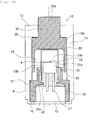
- Fig. 1A shows a schematic structure of a pyrotechnic actuator mechanism 10 according to the present invention (hereinafter simply referred to as "actuator mechanism"), illustrating a structure provided in a state before the combustion of an ignition charge, in a vertical cross section of the actuator mechanism 10.
- Fig. 1B shows a schematic structure of the actuator mechanism 10 provided in a state after the combustion of the ignition charge, in a vertical cross section thereof.
- Fig. 2 shows a schematic structure of an ignition unit 20 included in an igniter 25 of the actuator mechanism 10.
- a housing 11 of the actuator mechanism 10 has a circular cross section.
- An electric ignition igniter 25 (hereinafter simply referred to as "igniter”) is attached to an opening 12 disposed on one end side.
- the igniter 25 has an ignition unit 20 which includes the ignition charge.
- An example of the ignition unit 20 will now be explained on the basis of Fig. 2 .
- the ignition charge 22 is combusted by means of the ignition current supplied from the outside.
- a cup 21, the surface of which is covered with an insulating cover defines, in the cup 21, a space for disposing the ignition charge 22.
- a metal header 24 is arranged in the space, and the cup 21 is fixed to the metal header 24.
- a cylindrical charge holder 23 is provided on an upper surface of the metal header 24.
- the ignition charge 22 is held by the charge holder 23.
- the two conductive pins 27 are fixed to the metal header 24 by the aid of an insulator 29 so that the two conductive pins 27 are mutually in the insulated state.
- an open port of the cup 21, from which the two conductive pins 27 supported by the insulator 29 are allowed to extend outwardly, is protected by a mold portion 28 formed of a resin as shown in Fig. 1 in a state in which the insulation performance is satisfactorily maintained between the conductive pins 27.
- the mold portion 28 is formed by injection-molding a resin material in the production steps of producing the ignition unit 20.
- the ignition unit 20 configured in this way, when the voltage is applied between the two conductive pins 27 by an external power source, then the current flows through the bridge wire 26, and the ignition charge 22 is combusted thereby. In this situation, the combustion product, which is produced by the combustion of the ignition charge 22, is released from the opening of the charge holder 23 while breaking the cup 21.
- an ignition unit 20, which has no charge holder 23, may be used in another method.
- the portion, from which the combustion product is released is the portion 21a disposed in the vicinity of the center of the top of the cup 21.
- the space, which serves as the combustion chamber 9 is arranged in the vicinity of the portion 21a.
- the combustion chamber 9 is the closed space which is defined by a cover member 33 described later on, the ignition unit 20, and the mold portion 28. Therefore, the combustion product of the ignition charge 22 is sealed in the combustion chamber.
- the ignition charge 22 is preferably exemplified by a propellant containing zirconium and potassium perchlorate (ZPP), a propellant containing titanium hydride and potassium perchlorate (THPP), a propellantcontaining titanium and potassium perchlorate (TiPP), a propellant containing aluminum and potassium perchlorate (APP), a propellant containing aluminum and bismuth oxide (ABO), a propellant containing aluminum and molybdenum oxide (AMO), a propellant containing aluminum and copper oxide (ACO), a propellant containing aluminum and iron oxide (AFO), or a propellant composed of a combination of a plurality of the foregoing propellants.
- ZPP zirconium and potassium perchlorate
- THPP titanium hydride and potassium perchlorate
- TiPP propellantcontaining titanium and potassium perchlorate
- APP propellant containing aluminum and potassium perchlorate
- ABO propellant containing aluminum and bismuth oxide
- AMO propellant containing aluminum and
- propellants exhibit such characteristics that, although the propellants generate hot and high-pressure plasma during combustion immediately after ignition, when combustion products condense at a room temperature, the propellants do not contain gaseous components and the pressure generated decreases abruptly. It is also allowable that any propellant or pyrotechnic charge other than the above is used as the ignition charge, provided that the injection can be performed appropriately.
- any additional ignition charge is not especially arranged in the combustion chamber 9.
- a gas generating agent which is combusted by the combustion product produced by the combustion of the ignition charge 22 to generate the gas, can be also arranged in the combustion chamber 9.
- the gas generating agent it is possible to exemplify a single base smokeless propellant including 98% by mass of nitrocellulose, 0.8% by mass of diphenylamine, and 1.2% by mass of potassium sulfate.
- various gas generating agents used for a gas generator for airbags and a gas generator for seat belt pretensioners are examples of the gas generating agent.
- the combustion completion time can be changed for the gas generating agent by adjusting the dimension, the size, and the shape, especially the surface shape of the gas generating agent when the gas generating agent is arranged in the combustion chamber 9. Accordingly, the pressure transition in the combustion chamber 9 can be a desired transition.
- the igniter 25 is attached to one end side of the housing 11 in a state of being fixed to the igniter collar 6.
- a caulking portion 16 is provided on one end side of the housing 11.
- a step portion of the igniter collar 6 is allowed to abut against an annular step portion 15 formed on the inner wall surface of the housing 11.
- the opposite end portion of the igniter collar 6 is caulked by the caulking portion 16 to effect the fixation with respect to the housing 11.
- the igniter 25 including the ignition unit 20 is fixed to the igniter collar 6 by means of the mold portion 28.
- the cover member 33 is arranged so that the ignition unit 20 is covered therewith.
- the cover member 33 is arranged so that the portion 21a of the cup 21 of the ignition unit 20 (portion at which the combustion product of the ignition charge 22 is released) is covered therewith and the combustion chamber 9 as the closed space is formed between the cover member 33 and the ignition unit 20.
- the cover member 33 is composed of a first wall member 33a which is a wall member having no through-hole or the like existing therethrough and which is arranged opposingly to the portion 21a, and a second wall member 33b which is a wall member having no through-hole or the like existing therethrough in the same manner as described above, which is connected to the circumference of the first wall member 33a, and which extends in the axial direction of the cover member 33.
- the extending direction of the second wall member 33b is the same as the propulsion direction of the piston 30 described later on.
- a free end portion 33c of the second wall member 33b which is disposed on a side opposite to a connecting end portion with respect to the first wall member 33a, is open.
- the free end portion 33c is embedded and temporarily fixed in the resin material of the mold portion 28.
- the mold portion 28 functions as the "fixing member" for the cover member 33.
- the combustion chamber 9, which is defined by the cover member 33, the ignition unit 20, and the mold portion 28 has the hermetic sealing performance which is sufficiently secured or guaranteed.
- a protruding portion 13, which protrudes inwardly in the housing 11, is formed on a forward end side of the housing 11 (side of the upper end portion as viewed in Fig. 1A ).
- An opening 14, which connects the inside and the outside of the housing, is formed at a central portion of the protruding portion 13.
- an accommodating space 17, which is a columnar or cylindrical space and which accommodates the piston 30 made of metal therein, is formed in the housing 11.
- the accommodating space 17 is connected to the outside of the housing 11 via the opening 14.
- the piston 30 is formed integrally with a piston rod 32 which extends upwardly thereon.
- the piston rod 32 is inserted and fitted into the opening 14, and the piston 30 is inserted and fitted into the accommodating space 17. Then, the piston 30 and the piston rod 32 are movable in the axial direction in the housing 11, while maintaining a slidable state between the piston rod 32 and the opening 14 and a slidable state between the piston 30 and the accommodating space 17.
- the outer diameter of the piston 30 is approximately the same as or approximately slightly smaller than the inner diameter of the accommodating space 17.
- the correlation between the inner diameter of the accommodating space 17 and the outer diameter of the piston 30 is adjusted so that the movement can be caused smoothly when the piston 30 is moved. Further, it is also appropriate that a lubricant is applied between the outer circumferential surface of the piston 30 and the inner wall surface of the accommodating space. Note that in the state shown in Fig. 1A , the forward end surface of the piston rod 32a (upper end surface as viewed in Fig. 1A ) is flush with the outer surface of the protruding portion 13.
- the piston 30 has a cylindrical skirt portion 31 disposed at a lower portion.
- the inside of the skirt portion 31 forms an accommodating space 19 in which the ignition unit 20 of the igniter 25 is accommodated.
- the piston 30 and the piston rod 32 are positioned so that the first wall member 33a of the cover member 33 abuts against the lower surface of the piston 30 in the accommodating space 19.
- the distance (embedding distance) A which is included in the length in the axial direction of the second wall member 33b of the cover member 33 and by which the cover member 33 is embedded in the mold portion 28, is set to be larger than the distance by which the piston 30 is movable in the accommodating space 17 of the housing 11, i.e., the distance B between an inner wall surface 13a of the protruding portion 13 and a shoulder portion 35 generated or formed by the difference in the outer diameter between the piston 30 and the piston rod 32 in the vicinity of the connecting portion between the piston 30 and piston rod 32.
- the distance B is also the distance by which the piston 30 can be moved, and the distance B is also the distance by which the cover member 33 moved together with the piston 30 can be moved.
- the position, at which the movement of the cover member 33 is regulated together with the piston 30, corresponds to the maximum propulsion position according to the present invention.
- the fixing force i.e., the relatively weak fixing force
- the temporary fixed state between the second wall member 33b and the mold portion 28 is dissolved or canceled, and the cover member 33 becomes movable in the propulsion direction of the piston 30 so that the cover member 33 pushes the piston 30 upwardly. Therefore, when the ignition charge 22 is combusted, then the cover member 33 is moved in the upward direction as viewed in Fig. 1A , and the combustion chamber 9 is progressively expanded in the movement direction in accordance therewith.
- the first wall member 33a pushes the lower surface of the piston 30 upwardly.
- the upper surface 32a of the piston rod 32 protrudes from the housing 11.
- the cover member 33 is arranged in the columnar form in the mold portion 28 so that the cover member 33 can be moved smoothly in accordance with the combustion of the ignition charge 22, and any projection and any protrusion/recess are not formed for the second wall member 33b. Therefore, the cover member 33 is temporarily fixed to the mold portion 28 in the temporary fixing state in which the cover member 33 is withdrawable relatively easily from the mold portion 28.
- the embedding distance A of the second wall member 32b is set to be longer than the movable distance of the cover member 33 (movable distance of the piston 30) B. Therefore, even when the piston 30 arrives at the maximally propelled position (maximum propulsion position), i.e., the position at which the shoulder portion 35 abuts against the inner wall surface 13a, then the free end portion 33c of the cover member 33 exists at the inside of the mold portion 28, and the cover member 33 is not disengaged from the mold portion 28. Therefore, when the piston 30 is driven and propelled by the combustion of the ignition charge 22 in the actuator mechanism 10, the hermetic sealing performance of the combustion chamber 9 is maintained until arrival at the state in which the piston 30 is maximally propelled.
- the combustion energy can be efficiently transmitted to the piston 30 by the aid of the cover member 33 in the state in which the combustion product of the ignition charge 22 is sealed or enclosed in the combustion chamber 9.
- the injection pressure of the resin which is applied when the mold portion 28 is formed or molded, is preferably set to about 7 to 13 MPa in order to form the temporary fixing state for providing the hermetic sealing performance of the combustion chamber 9 and the efficient energy transmission as described above.
- the movement in the axial direction is prohibited in order that the piston 30 and the piston rod 32 do not protrude or jump out from the housing 11 before the combustion of the ignition charge 22.
- the circumferential surface of the opening 14 is lightly caulked, and thus the jumping out of the piston rod 32 is prohibited.
- the force which is not less than the resistance force brought about by the caulking, is exerted.
- the combustion product which contains the residue or the like produced by the combustion of the ignition charge 22 in the ignition unit 20 is sealed in the combustion chamber 9 which is the closed space formed by the cover member 33, the ignition unit 20, and the mold portion 28. Therefore, the combustion product does not leak to the outside, and the combustion product does not flow out to the outside of the housing 11 as well. Further, the combustion energy, which is generated by the combustion of the ignition charge 22, is principally received by the first wall member 33a opposed to the portion 21a. Therefore, the combustion energy pushes the cover member 33 upwardly to efficiently drive and propel the piston 22. In this way, the actuator mechanism 10 makes it possible to establish both of the suppression of the discharge or emission of the residue produced by the combustion of the ignition charge 22 and the maintenance of the preferable output efficiency brought about by the actuator.
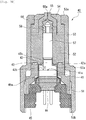
- Figs. 3A and 3B show a syringe 40 which uses the pyrotechnic actuator mechanism according to the present invention (hereinafter simply referred to as "actuator mechanism” as well) as the driving source.
- the actuator mechanism has substantially the same operation principle as that of the actuator mechanism 10 described in the first embodiment.
- Fig. 3A shows a schematic structure of the syringe 40, illustrating a structure in a state before the combustion of the ignition charge in the actuator mechanism, in a vertical cross section of the syringe 40.
- Fig. 3B shows a schematic structure of the syringe 40 in a state after the combustion of the ignition charge, in a vertical cross section thereof.
- injection solution which is to be injected into an injection target area by the syringe 40
- injection solution is generally referred to as "injection solution”.
- the component, which is to be delivered, for example, to a skin structure may be either dissolved or not dissolved in the injection objective substance.
- Any specified form of the injection objective substance is available without any problem as well, for which various forms can be adopted, including, for example, liquid and gel form, provided that the injection objective substance can be discharged to the injection target area from a discharge hole 55a of a nozzle 55 by being pressurized.
- the syringe 40 has a housing 53 which is formed to have a cylindrical shape.
- the housing 53 is provided with an electric ignition igniter for combusting the ignition charge and generating the energy in order to cause the discharge or injection.
- an electric ignition igniter for combusting the ignition charge and generating the energy in order to cause the discharge or injection.
- Figs. 3A and 3B only the ignition unit 41, which is included in the electric ignition igniter, is depicted. Note that the ignition unit 41 is substantially the same as the ignition unit 20 described in the first embodiment. Therefore, any detailed explanation of the ignition unit 41 will be omitted (see Fig. 2 ).
- the syringe 40 is incorporated with a piston 57 which transmits the combustion energy brought about by the combustion of the ignition charge in the ignition unit 41 to the injection solution accommodated in an accommodating space 56.
- the housing 53 is produced by the injection molding of the resin.
- the injection molding it is possible to use any known method.
- a resin material of the housing 53 for example, publicly-known nylon 6-12, polyarylate, polybutylene terephthalate, polyphenyiene sulfide, or liquid crystal polymer can be used.
- a filler such as a glass fiber or a glass filler may be included in these kinds of resin 20 to 80 mass % of the glass fiber can be included in the polybutylene terephthalate. 20 to 80 mass % of the glass fiber can be included in the polyphenylene sulfide, 20 to 80 mass % of mineral can be included in the liquid crystal polymer.
- a protruding portion 53a which protrudes in the inward direction of the housing 53, is formed on a forward end side of the housing 53 (side of the upper end portion as viewed in Fig. 3A ).
- An opening is formed at a central portion of the protruding portion 53a.
- the inside and the outside of the housing 53 are connected to one another by the opening.
- a first holder 54 is arranged at the inside of the housing 53 in a state in which the first holder 54 abuts against the protruding portion 53a.
- the first holder 54 retains a nozzle 55 at the inside thereof.
- a second holder 52 which is arranged to press the nozzle 55 with respect to the first holder 54, is arranged at the inside of the housing 53.
- the nozzle 55 and the second holder 52 may be formed in an integrated manner.
- a through-hole which has a constant diameter in the axial direction, is formed at the inside of the second holder 52. One end of the through-hole is communicated with the space in which the ignition unit 41 is arranged, and the other remaining end arrives at the side of the accommodating space 56 for accommodating the injection solution in the nozzle 55.
- a piston 57 made of metal is arranged in the through-hole so that the piston 57 can be propelled in the axial direction in the through-hole.
- One end thereof is directed to the side of the space in which the ignition unit 41 is arranged. Further, the other remaining end is directed to the side of the accommodating space 56 for accommodating the injection solution.
- a plunger 58 made of resin is provided on the forward end side of the piston 57.
- the space, which is formed between the plunger 58 and the nozzle 55, is the accommodating space 56 in which the injection solution is accommodated.
- the forward end portion of the plunger 58 has a shape which supplements or complements the shape of the accommodating space 56 on the side of the nozzle 55.
- the shape of the outer surface of the forward end portion of the plunger 58 is approximately coincident with the shape of the accommodating space 56 on the side of the nozzle 55. Therefore, it is possible to maximally decrease the amount of the injection solution which is left in the accommodating space 56 upon the completion of the discharge or injection of the injection solution.
- butyl rubber and silicon rubber can be adopted as the material for the plunger 58.
- the material include styrene-based elastomer, hydrogenated styrene-based elastomer, and the styrene-based elastomer and the hydrogenated styrene-based elastomer added with polyethylene, polypropylene, polybutene, polyolefin such as ⁇ -olefin copolymer, liquid paraffin, oil such as process oil, and powder inorganic matters such as talc, cast, and mica.
- the plunger 58 has a plurality of annular projections which are formed on the outer circumference of a columnar body.
- the projections are made of resin, and hence the projections are elastically deformed when the plunger 58 is inserted into the through-hole together with the piston 57. It is possible to enhance the degree of tight contact between the plunger 58 and the inner wall surface of the through-hole.
- a third holder 51 is arranged in the housing 58 so that the third holder 51 abuts against an end surface 52a of the second holder 52 on a side of the space in which the ignition unit 41 is arranged. Then, an igniter assembly, which is formed by caulking and fixing an intermediate assembly described later on including the ignition unit 41 with respect to the igniter collar 45, is retained by the third holder 51.
- the ignition unit 41 is fixed to the mold portion 44 formed of the resin.
- the cover member 42 is temporarily fixed to the mold portion 44 so that a release portion 41a of the cup of the ignition unit 41 for releasing the combustion product is covered therewith.
- the mold portion 44 of this embodiment corresponds to the mold portion 28 of the first embodiment, any detailed explanation of which is omitted.
- the cover member 42 will now be explained in detail.
- the cover member 42 is arranged so that the release portion 41a of the cup of the ignition unit 41 is covered therewith and the combustion chamber 43 as the closed space is formed between the cover member 42 and the ignition unit 41.
- the cover member 42 is composed of a first wall member 42a which is a wall member having no through-hole or the like existing therethrough and which is arranged opposingly to the portion 41a, and a second wall member 42b which is a wall member having no through-hole or the like existing therethrough in the same manner as described above, which is connected to the circumference of the first wall member 42a, and which extends in the axial direction of the cover member 42.
- the second wall member 42b is arranged along the side surface of the ignition unit 41, and the extending direction thereof is the same as the propulsion direction of the piston 57. Further, a free end portion of the second wall member 42b, which is disposed on a side opposite to a connecting end portion with respect to the first wall member 42a, is open. The free end portion is embedded and temporarily fixed in the resin material of the mold portion 44.
- the temporary fixation is the same as or equivalent to that of the first embodiment. In the state of temporary fixation, the hermetic sealing performance is sufficiently secured or guaranteed for the combustion chamber 43 which is defined by the cover member 42 and the ignition unit 41.
- a columnar protruding portion 42c which protrudes in the direction directed to the piston 57 from the first wall member 42a, is formed on the first wall member 42a of the cover member 42.
- the outer diameter of the protruding portion 42c is formed to be slightly smaller than the outer diameter of the piston 57, and the outer diameter of the first wall member 42a is formed to be larger than the outer diameter of the piston 57. Therefore, as shown in Fig. 3A , a step-shaped portion is formed on the cover member 42 in accordance with the difference between the outer diameter of the first wall member 42a and the outer diameter of the protruding portion 42c.
- the igniter assembly shown in Fig. 3A is formed by attaching the igniter collar 45 to the intermediate assembly in a state in which the ignition unit 41 is fixed to the mold portion 44 and the cover member 42 is temporarily fixed to the mold portion 44.
- the igniter collar 45 is provided with a caulking pawl 45a.
- the caulking pawl 45a is not bent.
- the intermediate assembly is inserted into the igniter collar 45 in this state.
- the caulking pawl 45a is bent to caulk the intermediate assembly, and thus the igniter assembly shown in Fig. 3A is formed.
- the igniter assembly which is formed by fixing the intermediate assembly including the ignition unit 41 to the igniter collar 45, is arranged in the housing 53 so that the igniter assembly abuts against the third holder 51. Further, the igniter assembly is fixed so that the igniter assembly is pressed against the third holder 51 at the end portion 53b of the housing 53 disposed on the side opposite to the protruding portion 53a.
- a seal member which includes, for example, an O-ring and a gasket, can be arranged at the respective abutment portions between the first holder 54 and the second holder 52, between the second holder 52 and the third holder 51, and between the third holder 51 and the igniter collar 45.
- FIG. 3A shows the state brought about before the combustion of the ignition charge of the ignition unit 41.
- the top surface of the protruding portion 42c of the cover member 42 is brought in contact with the end surface of the piston 57 on the side opposite to the plunger 58.
- the ignition current is supplied to the ignition charge to cause the combustion in this state, then the combustion product of the ignition charge flows from the portion 41a into the combustion chamber 43, and the pressure in the combustion chamber 43 is suddenly raised.
- the cover member 42 is temporarily fixed to the mold portion 44. Therefore, the cover member 42 is moved upwardly as viewed in Fig. 3A in accordance with the increase in the pressure in the combustion chamber 43.
- the piston 57 is pushed upwardly toward the forward end side of the syringe 40, and the piston 57 is driven and propelled. Further, the combustion chamber 43 is progressively expanded in the propulsion direction of the piston 57. In this situation, the outer diameter of the protruding portion 42c of the cover member 42 is formed to be slightly smaller than the outer diameter of the piston 57. Therefore, when the piston 57 is pushed upwardly, the protruding portion 42c progressively enters the through-hole in the second holder 52. Then, as shown in Fig.
- the embedding distance of the second wall member 42b in the mold portion 44 is also set to be longer than the movable distance of the cover member 42 and the piston 57, in the same manner as in the first embodiment.
- the movable distance of the cover member 42 and the like in this embodiment is the distance between the first wall member 42a of the cover member 42 and the end surface 52a of the second holder 52 for regulating the movement of the cover member 42, which corresponds to the distance C shown in Fig. 3B .
- the combustion product of the ignition charge is continuously sealed in the combustion chamber 43. Therefore, it is possible to efficiently realize the transmission of the combustion energy to the piston 57 by the aid of the cover member 42, while sufficiently suppressing the discharge or emission of the residue contained in the combustion product to the outside.
- the igniter assembly 60 is an assembly which is incorporated into the pyrotechnic actuator mechanism according to the present invention and which includes an ignition unit to cause the combustion of the ignition charge.
- the ignition unit 61 which is included in the igniter assembly 60, is substantially the same as the ignition unit 20 described in the first embodiment and the ignition unit 41 described in the second embodiment, any detailed explanation of which is omitted (see Fig. 2 ).
- the ignition unit 61 is fixed to a mold portion 64 formed of resin.
- a cover member 62 is temporarily fixed to the mold portion 64 so that the release portion of the cup of the ignition unit 61 for releasing the combustion product is covered therewith.
- the mold portion 64 of this embodiment corresponds to the mold portion 28 of the first embodiment and the mold portion 44 of the second embodiment, any detailed explanation of which is omitted.
- the mold portion 64 is provided in order to fix the ignition unit 61 to an igniter collar 70.
- a projection 73 is provided at a portion of an inner wall surface of the igniter collar 70 at which the mold portion 64 is formed so that the position is not changed after the mold portion 64 is formed at the inside of the igniter collar 70.
- a protrusion 71 which protrudes on the inner side of the igniter collar 70, is formed at the forward end side of the igniter collar 70 (side of the upper end portion as viewed in Fig. 4 ).
- An opening 72 is positioned at the center of the protrusion 71.
- a piston (not shown), to which the combustion energy brought about by the combustion of the ignition charge in the ignition unit 61 is transmitted, is arranged in the opening 72. That is, the opening 72 forms a part or all of the space in which the piston or the like is driven and propelled.
- the cover member 62 will now be explained in detail.
- the cover member 62 is arranged so that the portion of the cup of the ignition unit 61, from which the combustion product of the ignition charge is released, is covered therewith, and a combustion chamber 63, which is a closed space, is formed between the cover member 62 and the ignition unit 61.
- the cover member 62 is composed of a first wall member 62a which is a wall member having no through-hole or the like existing therethrough and which is arranged opposingly to the release portion, and a second wall member 62b which is a wall member having no through-hole or the like existing therethrough in the same manner as described above, which is connected to the circumference of the first wall member 62a, and which extends in the axial direction of the cover member 62.
- the second wall member 62b is arranged along the side surface of the ignition unit 61, and the extending direction thereof is the same as the output direction brought about by the igniter assembly 60.
- a free end portion of the second wall member 62b which is disposed on a side opposite to a connecting end portion with respect to the first wall member 62a, is open.
- the free end portion is embedded and temporarily fixed in the resin material of the mold portion 64.
- the temporary fixation is the same as or equivalent to those of the first embodiment and the second embodiment. In the state of temporary fixation, the hermetic sealing performance is sufficiently secured or guaranteed for the combustion chamber 63 which is defined by the cover member 62 and the ignition unit 61.
- a columnar protruding portion 62c which protrudes in the direction directed to the opening 72 from the first wall member 62a, is formed on the first wall member 62a of the cover member 62.
- the outer diameter of the protruding portion 62c is formed to be slightly smaller than the inner diameter of the opening 72, and the height of the protruding portion 62c is approximately the same as the thickness of the protruding portion 71.
- the position, at which the movement of the cover member 62 is regulated corresponds to the maximum propulsion position according to the present invention.
- the piston is pushed upwardly in accordance with the movement of the cover member 62. Accordingly, the combustion energy of the ignition charge in the igniter assembly 60 can be efficiently converted into the propulsion force of the piston.
- the embedding distance of the second wall member 62b in the mold portion 64 is also set to be longer than the movable distance of the cover member 62, in the same manner as in the first embodiment and the second embodiment.
- the movable distance of the cover member 62 in this embodiment is the distance between the first wall member 62a of the cover member 62 and the inner surface of the protruding portion 71 for regulating the movement of the cover member 62.
- the correlation is retained between the embedding distance and the movable distance, and thus the free end portion of the second wall member 62b exists in the mold portion 64 during the period of movement of the cover member 62, in the same manner as in the first embodiment and the second embodiment. Therefore, the combustion product of the ignition charge is continuously sealed in the combustion chamber 63. Therefore, it is possible to efficiently realize the transmission of the combustion energy by the aid of the cover member 62, while sufficiently suppressing the discharge of the residue contained in the combustion product to the outside.
- Fig. 5 shows a modified embodiment of the igniter assembly according to the present invention.
- the igniter assembly according to the modified embodiment is referred to by reference numeral 80.
- the components or parts of the igniter assembly 80 according to the modified embodiment which are common to those of the igniter assembly 60 according to the embodiment described above, are designated by the same reference numerals, any detailed explanation of which is omitted thereby.
- the igniter collar 70 of the igniter assembly 80 and the components or parts relevant thereto are the same as those of the igniter assembly 60.
- the mold portion 64 which is provided to fix the ignition unit 81 to the igniter collar 70 as described later on, is also common to the igniter assemblies 80, 60.
- the ignition unit 81 which is provided for the igniter assembly 80, has the ignition charge disposed at the inside thereof, in the same manner as the embodiment described above.
- the ignition current is supplied from the conductive pin, and thus the combustion of the ignition charge is caused.
- the ignition unit 81 does not have the cup 21 which is possessed, for example, by the ignition unit 20 according to the embodiment described above.
- a cover member 82 is provided in place of the cup 21. Accordingly, the space for accommodating the ignition charge is formed in the ignition unit 81. As described above, a part of the cup 21 is destroyed by the combustion of the ignition charge, and the combustion product of the ignition charge is released from the destroyed portion.
- the cup 21 also defines the release portion for releasing the combustion product in relation to the ignition unit 20 or the like.
- the cover member 81 has a first wall member 82a which is a wall member having no through-hole or the like existing therethrough and which forms the top surface, and a second wall member 82b which is a wall member having no through-hole or the like existing therethrough in the same manner as described above, which is connected to the circumference of the first wall member 82a, and which extends in the axial direction of the cover member 82.
- the both wall members have strengths to such an extent that the wall members are not destroyed by the pressure generated by the combustion of the ignition charge.
- the space, which is surrounded by the cover member 82, is filled with the ignition charge.
- the first wall member 82a is arranged opposingly to the charge holder (not shown in Fig. 5 , see Fig. 2 ) in which the ignition charge of the ignition unit 81 is placed.
- the second wall member 82b is arranged therearound. The cup does not exist, and hence the combustion product of the ignition charge is diffused radially in the cover member.
- the cover member 82 covers the release portion by means of the first wall member 82a and the second wall member 82b. Therefore, the internal space, which is formed by being covered with the cover member 82, is the combustion chamber 83 of the ignition unit 81.
- the free end portion of the second wall member 82b which is disposed on a side opposite to the connecting end portion with respect to the first wall member 82a, is embedded and temporarily fixed in the resin material of the mold portion 64.
- the temporary fixation is the same as or equivalent to that of the third embodiment described above.
- the second wall member 82b is not fixed to any specified portion of the ignition unit 81, for example, an unillustrated metal header 24.
- the second wall member 82b is merely temporarily fixed to the mold portion 64. Therefore, the movement of the cover member 82, which is directed toward the opening 72, is not inhibited when the ignition charge is combusted in the ignition unit 81.
- the embedding distance of the second wall member 82b embedded in the mold portion 64 is also set to be longer than the movable distance of the cover member 82, in the same manner as in the third embodiment described above.
- the movable distance of the cover member 82 is the distance between the first wall member 82a of the cover member 82 and the inner surface of the protruding portion 71 which regulates the movement of the cover member 82. In this way, the correlation is retained between the embedding distance and the movable distance, and thus the free end portion of the second wall member 82b exists in the mold portion 64 during the period of movement of the cover member 82, in the same manner as in the third embodiment described above. Therefore, the combustion product of the ignition charge is continuously sealed in the combustion chamber 83.
Landscapes
- Engineering & Computer Science (AREA)
- Health & Medical Sciences (AREA)
- General Engineering & Computer Science (AREA)
- General Health & Medical Sciences (AREA)
- Veterinary Medicine (AREA)
- Biomedical Technology (AREA)
- Heart & Thoracic Surgery (AREA)
- Hematology (AREA)
- Life Sciences & Earth Sciences (AREA)
- Animal Behavior & Ethology (AREA)
- Vascular Medicine (AREA)
- Public Health (AREA)
- Anesthesiology (AREA)
- Chemical & Material Sciences (AREA)
- Analytical Chemistry (AREA)
- Physics & Mathematics (AREA)
- Fluid Mechanics (AREA)
- Mechanical Engineering (AREA)
- Actuator (AREA)
- Infusion, Injection, And Reservoir Apparatuses (AREA)
- Automotive Seat Belt Assembly (AREA)
Abstract
Description
- The present invention relates to a pyrotechnic actuator mechanism which obtains an output by means of the combustion of an ignition charge, a syringe which utilizes the same, and an igniter assembly which is usable in order to ignite or inflame the ignition charge.
- A pyrotechnic actuator mechanism, which is an actuator mechanism to obtain an output by moving a piston by means of the force of an ignition charge, is used for apparatuses including, for example, an airbag system for vehicles, a pedestrian protection system, a current breaker, a perforator, and a fire extinguishing system. Further, a syringe, which discharges or injects an injection objective substance by means of a pressurized piston, is also known in the field of medical treatment. A pyrotechnic actuator mechanism is widely investigated as a driving source for the syringe as described above. For example, Patent Literature 1 discloses an actuator mechanism which obtains a predetermined output by developing a bellows cup which is expandable as shown in
Fig. 1 or a bendable/stretchable cup which is shown in Fig. 6, by means of a combustion product produced by the combustion of an ignition charge. - In the case of the pyrotechnic actuator mechanism as described above, the ignition charge is used as the driving source for the piston. Therefore, any residue is produced to no small extent upon the combustion of the ignition charge. Then, even when the produced residue is in a small amount, it is preferable that the residue is not discharged or emitted to the outside of the actuator mechanism. For example, in the case of a pyrotechnic actuator mechanism shown in Patent Literature 2, a sack (see Fig. 6A), which has been folded up from the beginning, is expanded (see Fig. 6B) by a combustion product produced by the combustion of an ignition charge, and thus an output is obtained for an actuator. In this situation, the combustion product is in a state of being sealed by the sack. Therefore, the combustion product, which contains the residue, hardly leaks out to the outside.
- Further, in the case of a pyrotechnic actuator mechanism shown in Patent Literature 3, such a structure is adopted that a piston is extruded by raising the pressure of a gas chamber in accordance with an operation of a gas generator provided on one end side of a cylinder. The movement of the piston is continued until the piston collides with a bush provided in the cylinder. In this case, the clearance is extremely decreased for the cylinder and a main body unit of the piston. However, the combustion residue is not completely prevented from being discharged or emitted to the outside of the cylinder.
-
- Patent Literature 1: United States Patent No.
7,063,019 - Patent Literature 2: United States Patent No.
7,455,655 - Patent Literature 3: Japanese Patent Application Laid-Open No.
2009-61803 - In the case of the pyrotechnic actuator mechanism, the output is obtained by utilizing the energy obtained by the combustion of the ignition charge. Therefore, the output can be made relatively large, while providing a relatively small structure of the actuator mechanism. It is possible to say that the pyrotechnic actuator mechanism is a useful actuator mechanism in which the output efficiency is extremely satisfactory. However, the residue is produced when the ignition charge is combusted. Therefore, it is preferable that the residue does not leak out to the outside, in view of the hygiene and in view of the influence exerted, for example, on mechanical parts disposed around the actuator mechanism.
- However, if it is intended to seal the combustion product of the ignition charge in the certain space by means of the bag such as the sack or the like as mentioned in Patent Literature 1 and Patent Literature 2 described above, the relatively large pressure is easily exerted by the high combustion energy and the contained combustion residue. On the other hand, when the sealed space is formed by bending the member such as the bellows cup as mentioned in Patent Literature 1, the pressure is easily concentrated at the bent portion. Therefore, it is possible to find out any scope for improvement in view of the strength of the sealed space. Further, it is impossible to sufficiently suppress the discharge or emission of the residue to the outside by merely adjusting the clearance as mentioned in Patent Literature 3.
- Accordingly, in view of the problems described above, an object of the present invention is to provide a technique which preferably suppresses the discharge or emission of the residue produced by the combustion of the ignition charge to the outside.
- In order to solve the problems described above, the present inventors especially paid the attention to a cover member which covers an ignition unit including an ignition charge. Specifically, the present invention resides in a pyrotechnic actuator mechanism which has an ignition unit including an ignition charge to be ignited or inflamed by an ignition current supplied from outside and which includes a piston constructed to be driven and propelled in a propulsion hole provided in a housing in accordance with combustion energy of the ignition charge; the pyrotechnic actuator mechanism comprising a cover member which covers a predetermined portion of the ignition unit including at least a release portion for releasing, from the ignition unit, a combustion product produced by combustion of the ignition charge in the ignition unit, which is formed to define a predetermined closed space between the cover member and the ignition unit, and which is arranged to transmit the combustion energy of the ignition charge to the piston; and a fixing member which fixes the ignition unit before and after the combustion of the ignition charge. Then, the cover member includes a first wall member which is a wall member for defining the predetermined closed space, which is opposed to the predetermined portion of the ignition unit, and which is brought in contact with the piston; and a second wall member which is a wall member connected to the first wall member, for defining the predetermined closed space, which extends in the propulsion direction of the piston, and which has a free end portion disposed on a side opposite to a connecting end portion with respect to the first wall member, the free end portion being embedded in the fixing member. Further, the cover member is moved in the propulsion direction so that the predetermined closed space is expanded in the propulsion direction of the piston when the ignition charge is combusted, and the movement of the cover member in the propulsion direction is regulated so that a state, in which the free end portion of the second wall member is embedded in the fixing member, is maintained at a maximum propulsion position of the cover member.
- The pyrotechnic actuator mechanism according to the present invention uses the ignition charge as the output source for the actuator. The ignition charge is exemplified, for example, by ZPP (mixture of zirconium and potassium perchlorate) and black powder (for example, boron saltpeter). Then, the ignition unit, which includes the ignition charge, is covered by the cover member, and thus the combustion product of the ignition charge is sealed in the predetermined closed space defined between the cover member and the ignition unit. Note that it is not necessarily indispensable that the cover member should cover the entire ignition unit. It is enough that the cover member is arranged with respect to the ignition unit so that the cover member covers at least the predetermined portion at which the combustion product is released. That is, it is appropriate that the cover or covering is formed for the ignition unit by the cover member in view of the suppression of the discharge or emission of the combustion product or the ignition charge to the outside. Note that it is enough that the housing forms the propulsion hole in which the piston is driven and propelled. The housing may be an outer shell container itself of the actuator mechanism itself or any other part arranged in an outer hull container.
- Then, the cover member is the member which is provided to transmit the combustion energy of the ignition charge to the piston so that the piston is driven and propelled. The cover member has the first wall member and the second wall member for defining the predetermined closed space described above. The first wall member is the wall member which is opposed to the predetermined portion for releasing the combustion product of the ignition charge and which is arranged to be brought in contact with the piston. On this account, the first wall member is constructed to receive the pressure from the combustion product, i.e., the combustion energy generated by the combustion of the ignition charge to a relatively great extent. As a result, the first wall member receives the force to make separation from the ignition unit. The force is transmitted to the piston brought in contact therewith. Therefore, the direction of separation is the propulsion direction of the piston. Note that as for the contact between the first wall member and the piston, the first wall member and the piston may be arranged in a contact state in the uncombusted state of the ignition charge. In another method, the both may be arranged to be brought in contact with each other after the combustion, even when the both are not brought in contact in the uncombusted state.
- On the other hand, the second wall member is the wall member which is connected to the first wall member. Therefore, when the first wall member receives the force in accordance with the combustion of the ignition charge as described above, the second wall member is also moved in accordance therewith in the direction in which the first wall member is separated from the ignition unit. In this situation, the free end portion of the second wall member is in the state of being embedded in the fixing member. However, the free end portion is not consequently in a state in which the free end portion is fixed by the fixing member. Therefore, the separation from the ignition unit is not inhibited when the ignition charge is combusted. In other words, the free end portion of the second wall member is fixed to such an extent that the free end portion can be moved by receiving the combustion energy of the ignition charge. On the other hand, the free end portion of the second wall member is embedded in the fixing member, and thus the hermetic sealing performance of the predetermined closed space described above, i.e., the ability to suppress the discharge or emission of the combustion product of the ignition charge is secured or guaranteed.
- Then, when the ignition charge is combusted, the first wall member is principally pressurized by the combustion product as described above. Accordingly, the cover member is moved in the propulsion direction of the piston, and the predetermined closed space is progressively expanded in the propulsion direction. In accordance with the movement of the cover member, the combustion energy of the ignition charge is preferably transmitted to the piston by the aid of the cover member. Further, the state, in which the free end portion of the second wall member is embedded in the fixing member, is maintained during the movement of the cover member, i.e., during the period until the cover member arrives at the maximum propulsion position after the start of the movement. Therefore, the hermetic sealing performance of the predetermined closed space is always maintained in the period of movement of the cover member.
- In this way, in the pyrotechnic actuator mechanism according to the present invention, both of the maintenance of the predetermined closed space for sealing the combustion product of the ignition charge and the efficient transmission of the combustion energy to the piston are fulfilled. As a result, the discharge or emission of the residue contained in the combustion product to the outside is preferably suppressed without decreasing the output efficiency of the pyrotechnic actuator. Note that the cover member receives the combustion energy, and hence the cover member is preferably made of metal having a high thermal strength. Further, it is preferable that any fragile portion or the like, on which the pressure is concentrated, is not formed so that the predetermined closed space is maintained before and after the combustion of the ignition charge as well.
- In this context, in the pyrotechnic actuator mechanism described above, an embedded state of the free end portion in the fixing member may be maintained by means of such an arrangement that an embedding distance of the second wall member in the fixing member in an uncombusted state of the ignition charge, i.e., an embedding depth is longer than a movement distance of the cover member in the propulsion direction at a maximum propulsion position of the cover member. When the arrangement as described above is adopted, the hermetic sealing performance of the predetermined closed space is thereby preferably maintained during the period of movement of the cover member caused by the combustion of the ignition charge.
- Further, in the pyrotechnic actuator mechanism described above, the cover member may further include a protruding portion which is disposed at a portion of contact with the piston at the first wall member and which protrudes toward the piston. In this case, an outer diameter of the protruding portion is formed to be smaller than an outer diameter of the piston, and an outer diameter of the first wall member is formed to be larger than the outer diameter of the piston. When the outer diameter of the protruding portion is formed to be smaller than the outer diameter of the piston as described above, the protruding portion can thereby enter the propulsion hole of the piston as well. Therefore, the protruding portion enters the propulsion hole during the period until arrival of the cover member at the maximum propulsion position, and thus the distance, by which the cover member can be moved in accordance with the combustion of the ignition charge, can be secured to be longer. It is expected to improve the output of the pyrotechnic actuator mechanism.
- Note that the pyrotechnic actuator mechanism may be constructed as follows in relation to the maximum propulsion position of the cover member. That is, the cover member arrives at the maximum propulsion position by bringing the first wall member in contact with an end surface of the housing provided with the propulsion hole and regulating the movement of the cover member in the propulsion direction. The movement of the cover member is regulated by the contact of the first wall member with the end surface of the housing. However, in the contact state, the protruding portion is in a state of entering the propulsion hole of the piston. Therefore, it is expected to improve the output of the pyrotechnic actuator mechanism as described above.
- Further, in the pyrotechnic actuator mechanism described above, a gas generating agent, which is combusted by a combustion product of the ignition charge to produce a gas, may be arranged in the protruding portion. The amount of energy applied to the cover member is increased by further arranging the gas generating agent. Therefore, the output of the pyrotechnic actuator mechanism is improved. Note that for example, a nitrocellulose-based generating agent can be utilized as the gas generating agent.
- In this context, in the pyrotechnic actuator mechanism described above, the fixing member may include a mold portion which is formed of a resin material and which fixes the ignition unit, and the cover member may be temporarily fixed by the mold portion in a state in which the first wall member is not embedded in the mold portion and in a state in which a wall surface of the second wall member including the free end portion is embedded in the mold portion. Then, the mold portion may fix the ignition unit with respect to an inner wall surface of the housing. When the pyrotechnic actuator mechanism is constructed by adopting the mold portion based on the resin material, it is thereby easy to produce the mechanism. Note that the temporary fixation of the second wall member refers to a state in which the free end portion of the second wall member is fixed to such an extend that the free end portion of the second wall member can be moved in the mold portion, by means of the pressure exerted on the cover member in accordance with the combustion of the ignition charge.
- Further, in the form in which the second wall member is embedded in the mold portion, it is preferable that the second wall member is embedded in the mold portion so that the second wall member is in a straight column state along with the propulsion direction in the mold portion. The straight column state is such a state that the outer diameter and the inner diameter of the second wall member are approximately constant in the embedding depth direction in the mold portion. When the second wall member is embedded in the straight column state as described above, the free end portion is easily moved in the mold portion by the pressurizing force upon the combustion of the ignition charge.
- Note that the pyrotechnic actuator mechanism described above is applicable to various ways of use, because the residue is not discharged or emitted to the outside, and it is possible to obtain the high output. For example, the pyrotechnic actuator mechanism can be also preferably utilized in the field of medical equipment in which an extremely high hygiene environment is required. For example, the pyrotechnic actuator mechanism can be adopted as an actuator for discharging or injecting an injection objective substance by a syringe. In this case, a syringe can be constructed by the pyrotechnic actuator mechanism as described above, an enclosure in which an injection objective substance to be injected into an injection target area is enclosed, and a nozzle unit which has a flow passage for discharging or injecting the pressurized injection objective substance into the injection target area, the injection objective substance enclosed in the enclosure being pressurized by the aid of the piston driven and propelled by the combustion of the ignition charge in the pyrotechnic actuator. Other than the above, the pyrotechnic actuator mechanism described above may be also preferably adapted, for example, to a current breaker and a perforator.
- Further, the present invention can be also grasped from an aspect of an igniter for an ignition charge in order to obtain a predetermined output. That is, the present invention resides in an igniter assembly comprising an electric ignition igniter which has an ignition unit including an ignition charge; an igniter collar which accommodates the electric ignition igniter; a cover member which covers a predetermined portion of the ignition unit including at least a release portion for releasing, from the ignition unit, a combustion product produced by combustion of the ignition charge in the ignition unit, which is formed to define a predetermined closed space between the cover member and the ignition unit, and which outputs combustion energy of the ignition charge in a predetermined output direction; and a fixing member which fixes the electric ignition igniter unit to the igniter collar before and after the combustion of the ignition charge. Then, the cover member includes a first wall member which is a wall member for defining the predetermined closed space and which is opposed to the predetermined portion of the ignition unit; and a second wall member which is a wall member connected to the first wall member, for defining the predetermined closed space, which extends in the predetermined output direction, and which has a free end portion disposed on a side opposite to a connecting end portion with respect to the first wall member, the free end portion being embedded in the fixing member. Further, the cover member is moved in the predetermined output direction so that the predetermined closed space is expanded in the predetermined output direction when the ignition charge is combusted, and the movement of the cover member in the predetermined output direction is regulated so that a state, in which the free end portion of the second wall member is embedded in the fixing member, is maintained at a maximum propulsion position of the cover member. Accordingly, in relation to the igniter assembly, the output, which is obtained by the combustion, can be improved as far as possible, while preferably suppressing the residue produced by the combustion of the ignition charge from being discharged or emitted to the outside.
- Note that the technical concept of the present invention, which is disclosed in relation to the pyrotechnic actuator mechanism described above, can be also applied to the igniter assembly provided that any technical inconsistency does not arise. For example, an embedded state of the free end portion in the fixing member may be maintained by means of such an arrangement that an embedding distance of the second wall member in the fixing member in an uncombusted state of the ignition charge is longer than a movement distance of the cover member in the predetermined output direction at a maximum propulsion position of the cover member. Further, the fixing member may include a mold portion which is formed of a resin material and which fixes the electric ignition igniter to the igniter collar; and the cover member may be temporarily fixed by the mold portion in a state in which the first wall member is not embedded in the mold portion and in a state in which a wall surface of the second wall member including the free end portion is embedded in the mold portion. Further, a gas generating agent, which is combusted by a combustion product to generate a gas, may be arranged at a position disposed in the cover member at which the combustion product of the ignition charge can be brought in contact therewith. The ignition unit can include an ignition mechanism such as a bridge wire or the like which is brought in contact with the ignition charge and which is red-heated by the ignition current. No problem arises even when any mechanism other than the bridge wire is adopted as the ignition mechanism.
- Further, in the igniter assembly described above, the igniter collar may have a stopper member with which the cover member is brought in contact when the cover member is moved in the predetermined output direction in an igniter accommodating space for accommodating the electric ignition igniter. In this case, when the ignition charge is combusted and the cover member is moved in the predetermined output direction, then the first wall member is brought in contact with the stopper member, the movement of the cover member in the predetermined output direction is regulated, and thus the cover member arrives at the maximum propulsion position. That is, the igniter collar accommodates the electric ignition igniter, while the limit of expansion of the predetermined closed space is determined by the stopper member.
- Further, in the igniter assembly described above, the electric ignition igniter may have a header portion which retains the ignition charge; and the cover member may form, on the header portion, an ignition charge accommodating space for accommodating the ignition charge together with the header portion in a state in which the cover member is not fixed to the header portion. That is, the cover member serves for both the definition of the space for accommodating the ignition charge and the definition of the predetermined closed space. Therefore, it is possible to decrease the number of constitutive parts of the igniter assembly.
- It is possible to provide the technique which preferably suppresses the discharge or emission of the residue produced by the combustion of the ignition charge to the outside.
-
-
Fig. 1A shows a schematic structure of a pyrotechnic actuator mechanism according to the present invention, illustrating a structure brought about before the combustion of an ignition charge. -
Fig. 1B shows a schematic structure of the pyrotechnic actuator mechanism according to the present invention, illustrating a structure brought about after the combustion of the ignition charge. -
Fig. 2 shows a structure of an igniter included in the pyrotechnic actuator mechanism shown inFigs. 1A and1B . -
Fig. 3A shows a schematic structure of a syringe according to the present invention, illustrating a structure before the combustion of the ignition charge. -
Fig. 3B shows a schematic structure of the syringe according to the present invention, illustrating a structure after the combustion of the ignition charge. -
Fig. 4 shows a schematic structure of a first igniter assembly according to the present invention. -
Fig. 5 shows a schematic structure of a second igniter assembly according to the present invention. - An explanation will be made below with reference to the drawings about an embodiment of the present invention. Note that the structure or construction of the following embodiment is described by way of example, and the present invention is not limited to the structure or construction of the embodiment.
- <Structure of
pyrotechnic actuator mechanism 10> -
Fig. 1A shows a schematic structure of apyrotechnic actuator mechanism 10 according to the present invention (hereinafter simply referred to as "actuator mechanism"), illustrating a structure provided in a state before the combustion of an ignition charge, in a vertical cross section of theactuator mechanism 10. Further,Fig. 1B shows a schematic structure of theactuator mechanism 10 provided in a state after the combustion of the ignition charge, in a vertical cross section thereof. Further,Fig. 2 shows a schematic structure of anignition unit 20 included in anigniter 25 of theactuator mechanism 10. - A
housing 11 of theactuator mechanism 10 has a circular cross section. An electric ignition igniter 25 (hereinafter simply referred to as "igniter") is attached to anopening 12 disposed on one end side. Theigniter 25 has anignition unit 20 which includes the ignition charge. An example of theignition unit 20 will now be explained on the basis ofFig. 2 . In theignition unit 20, theignition charge 22 is combusted by means of the ignition current supplied from the outside. Specifically, acup 21, the surface of which is covered with an insulating cover, defines, in thecup 21, a space for disposing theignition charge 22. Then, ametal header 24 is arranged in the space, and thecup 21 is fixed to themetal header 24. Further, acylindrical charge holder 23 is provided on an upper surface of themetal header 24. Theignition charge 22 is held by thecharge holder 23. Abridge wire 26, which electrically connects oneconductive pin 27 and themetal header 24, is wired at the bottom portion of theignition charge 22. Note that the twoconductive pins 27 are fixed to themetal header 24 by the aid of aninsulator 29 so that the twoconductive pins 27 are mutually in the insulated state. Further, an open port of thecup 21, from which the twoconductive pins 27 supported by theinsulator 29 are allowed to extend outwardly, is protected by amold portion 28 formed of a resin as shown inFig. 1 in a state in which the insulation performance is satisfactorily maintained between the conductive pins 27. Themold portion 28 is formed by injection-molding a resin material in the production steps of producing theignition unit 20. - In the
ignition unit 20 configured in this way, when the voltage is applied between the twoconductive pins 27 by an external power source, then the current flows through thebridge wire 26, and theignition charge 22 is combusted thereby. In this situation, the combustion product, which is produced by the combustion of theignition charge 22, is released from the opening of thecharge holder 23 while breaking thecup 21. Note that anignition unit 20, which has nocharge holder 23, may be used in another method. In the case of theignition unit 20 shown inFig. 2 , the portion, from which the combustion product is released, is theportion 21a disposed in the vicinity of the center of the top of thecup 21. In this arrangement, as shown inFig. 1A , the space, which serves as thecombustion chamber 9, is arranged in the vicinity of theportion 21a. Thecombustion chamber 9 is the closed space which is defined by acover member 33 described later on, theignition unit 20, and themold portion 28. Therefore, the combustion product of theignition charge 22 is sealed in the combustion chamber. - Note that the
ignition charge 22 is preferably exemplified by a propellant containing zirconium and potassium perchlorate (ZPP), a propellant containing titanium hydride and potassium perchlorate (THPP), a propellantcontaining titanium and potassium perchlorate (TiPP), a propellant containing aluminum and potassium perchlorate (APP), a propellant containing aluminum and bismuth oxide (ABO), a propellant containing aluminum and molybdenum oxide (AMO), a propellant containing aluminum and copper oxide (ACO), a propellant containing aluminum and iron oxide (AFO), or a propellant composed of a combination of a plurality of the foregoing propellants. These propellants exhibit such characteristics that, although the propellants generate hot and high-pressure plasma during combustion immediately after ignition, when combustion products condense at a room temperature, the propellants do not contain gaseous components and the pressure generated decreases abruptly. It is also allowable that any propellant or pyrotechnic charge other than the above is used as the ignition charge, provided that the injection can be performed appropriately. - In this case, any additional ignition charge is not especially arranged in the
combustion chamber 9. However, for example, a gas generating agent, which is combusted by the combustion product produced by the combustion of theignition charge 22 to generate the gas, can be also arranged in thecombustion chamber 9. As for an example of the gas generating agent, it is possible to exemplify a single base smokeless propellant including 98% by mass of nitrocellulose, 0.8% by mass of diphenylamine, and 1.2% by mass of potassium sulfate. Further, it is also possible to use various gas generating agents used for a gas generator for airbags and a gas generator for seat belt pretensioners. The combustion completion time can be changed for the gas generating agent by adjusting the dimension, the size, and the shape, especially the surface shape of the gas generating agent when the gas generating agent is arranged in thecombustion chamber 9. Accordingly, the pressure transition in thecombustion chamber 9 can be a desired transition. - Then, the
igniter 25 is attached to one end side of thehousing 11 in a state of being fixed to theigniter collar 6. Specifically, acaulking portion 16 is provided on one end side of thehousing 11. A step portion of theigniter collar 6 is allowed to abut against anannular step portion 15 formed on the inner wall surface of thehousing 11. In this state, the opposite end portion of theigniter collar 6 is caulked by thecaulking portion 16 to effect the fixation with respect to thehousing 11. Note that theigniter 25 including theignition unit 20 is fixed to theigniter collar 6 by means of themold portion 28. - Further, the
cover member 33 is arranged so that theignition unit 20 is covered therewith. In particular, thecover member 33 is arranged so that theportion 21a of thecup 21 of the ignition unit 20 (portion at which the combustion product of theignition charge 22 is released) is covered therewith and thecombustion chamber 9 as the closed space is formed between thecover member 33 and theignition unit 20. Then, thecover member 33 is composed of afirst wall member 33a which is a wall member having no through-hole or the like existing therethrough and which is arranged opposingly to theportion 21a, and asecond wall member 33b which is a wall member having no through-hole or the like existing therethrough in the same manner as described above, which is connected to the circumference of thefirst wall member 33a, and which extends in the axial direction of thecover member 33. The extending direction of thesecond wall member 33b is the same as the propulsion direction of thepiston 30 described later on. Further, afree end portion 33c of thesecond wall member 33b, which is disposed on a side opposite to a connecting end portion with respect to thefirst wall member 33a, is open. Thefree end portion 33c is embedded and temporarily fixed in the resin material of themold portion 28. In this viewpoint, themold portion 28 functions as the "fixing member" for thecover member 33. In the state of temporary fixation, thecombustion chamber 9, which is defined by thecover member 33, theignition unit 20, and themold portion 28, has the hermetic sealing performance which is sufficiently secured or guaranteed. - In this arrangement, a protruding
portion 13, which protrudes inwardly in thehousing 11, is formed on a forward end side of the housing 11 (side of the upper end portion as viewed inFig. 1A ). Anopening 14, which connects the inside and the outside of the housing, is formed at a central portion of the protrudingportion 13. Further, anaccommodating space 17, which is a columnar or cylindrical space and which accommodates thepiston 30 made of metal therein, is formed in thehousing 11. Theaccommodating space 17 is connected to the outside of thehousing 11 via theopening 14. Thepiston 30 is formed integrally with apiston rod 32 which extends upwardly thereon. In a state shown inFig. 1A , thepiston rod 32 is inserted and fitted into theopening 14, and thepiston 30 is inserted and fitted into theaccommodating space 17. Then, thepiston 30 and thepiston rod 32 are movable in the axial direction in thehousing 11, while maintaining a slidable state between thepiston rod 32 and theopening 14 and a slidable state between thepiston 30 and theaccommodating space 17. For example, the outer diameter of thepiston 30 is approximately the same as or approximately slightly smaller than the inner diameter of theaccommodating space 17. The correlation between the inner diameter of theaccommodating space 17 and the outer diameter of thepiston 30 is adjusted so that the movement can be caused smoothly when thepiston 30 is moved. Further, it is also appropriate that a lubricant is applied between the outer circumferential surface of thepiston 30 and the inner wall surface of the accommodating space. Note that in the state shown inFig. 1A , the forward end surface of thepiston rod 32a (upper end surface as viewed inFig. 1A ) is flush with the outer surface of the protrudingportion 13. - Further, the
piston 30 has acylindrical skirt portion 31 disposed at a lower portion. The inside of theskirt portion 31 forms anaccommodating space 19 in which theignition unit 20 of theigniter 25 is accommodated. In the state shown inFig. 1A in which theigniter 25 is accommodated in thehousing 11 by the aid of theigniter collar 6, thepiston 30 and thepiston rod 32 are positioned so that thefirst wall member 33a of thecover member 33 abuts against the lower surface of thepiston 30 in theaccommodating space 19. - In this arrangement, the distance (embedding distance) A, which is included in the length in the axial direction of the
second wall member 33b of thecover member 33 and by which thecover member 33 is embedded in themold portion 28, is set to be larger than the distance by which thepiston 30 is movable in theaccommodating space 17 of thehousing 11, i.e., the distance B between aninner wall surface 13a of the protrudingportion 13 and ashoulder portion 35 generated or formed by the difference in the outer diameter between thepiston 30 and thepiston rod 32 in the vicinity of the connecting portion between thepiston 30 andpiston rod 32. When thepiston 30 is moved by the distance B, the movement thereof is regulated by the protrudingportion 13. Therefore, the distance B is also the distance by which thepiston 30 can be moved, and the distance B is also the distance by which thecover member 33 moved together with thepiston 30 can be moved. In this arrangement, the position, at which the movement of thecover member 33 is regulated together with thepiston 30, corresponds to the maximum propulsion position according to the present invention. - As for the embedding of the
second wall member 33b in themold portion 28, the fixing force (i.e., the relatively weak fixing force) is generated to such an extent that thecover member 33 is pushed in the propulsion direction by the pressure in thecombustion chamber 9 generated when theignition charge 22 is combusted in theignition unit 20, the temporary fixed state between thesecond wall member 33b and themold portion 28 is dissolved or canceled, and thecover member 33 becomes movable in the propulsion direction of thepiston 30 so that thecover member 33 pushes thepiston 30 upwardly. Therefore, when theignition charge 22 is combusted, then thecover member 33 is moved in the upward direction as viewed inFig. 1A , and thecombustion chamber 9 is progressively expanded in the movement direction in accordance therewith. In this situation, thefirst wall member 33a pushes the lower surface of thepiston 30 upwardly. Thus, as shown inFig. 1B , theupper surface 32a of thepiston rod 32 protrudes from thehousing 11. In this way, thecover member 33 is arranged in the columnar form in themold portion 28 so that thecover member 33 can be moved smoothly in accordance with the combustion of theignition charge 22, and any projection and any protrusion/recess are not formed for thesecond wall member 33b. Therefore, thecover member 33 is temporarily fixed to themold portion 28 in the temporary fixing state in which thecover member 33 is withdrawable relatively easily from themold portion 28. - In this arrangement, as described above, the embedding distance A of the second wall member 32b is set to be longer than the movable distance of the cover member 33 (movable distance of the piston 30) B. Therefore, even when the
piston 30 arrives at the maximally propelled position (maximum propulsion position), i.e., the position at which theshoulder portion 35 abuts against theinner wall surface 13a, then thefree end portion 33c of thecover member 33 exists at the inside of themold portion 28, and thecover member 33 is not disengaged from themold portion 28. Therefore, when thepiston 30 is driven and propelled by the combustion of theignition charge 22 in theactuator mechanism 10, the hermetic sealing performance of thecombustion chamber 9 is maintained until arrival at the state in which thepiston 30 is maximally propelled. In this way, in the case of theactuator mechanism 10, the combustion energy can be efficiently transmitted to thepiston 30 by the aid of thecover member 33 in the state in which the combustion product of theignition charge 22 is sealed or enclosed in thecombustion chamber 9. Note that the injection pressure of the resin, which is applied when themold portion 28 is formed or molded, is preferably set to about 7 to 13 MPa in order to form the temporary fixing state for providing the hermetic sealing performance of thecombustion chamber 9 and the efficient energy transmission as described above. - Note that the movement in the axial direction is prohibited in order that the
piston 30 and thepiston rod 32 do not protrude or jump out from thehousing 11 before the combustion of theignition charge 22. Specifically, the circumferential surface of theopening 14 is lightly caulked, and thus the jumping out of thepiston rod 32 is prohibited. When theignition charge 22 is combusted, the force, which is not less than the resistance force brought about by the caulking, is exerted. - As described above, in the
actuator mechanism 10, the combustion product, which contains the residue or the like produced by the combustion of theignition charge 22 in theignition unit 20, is sealed in thecombustion chamber 9 which is the closed space formed by thecover member 33, theignition unit 20, and themold portion 28. Therefore, the combustion product does not leak to the outside, and the combustion product does not flow out to the outside of thehousing 11 as well. Further, the combustion energy, which is generated by the combustion of theignition charge 22, is principally received by thefirst wall member 33a opposed to theportion 21a. Therefore, the combustion energy pushes thecover member 33 upwardly to efficiently drive and propel thepiston 22. In this way, theactuator mechanism 10 makes it possible to establish both of the suppression of the discharge or emission of the residue produced by the combustion of theignition charge 22 and the maintenance of the preferable output efficiency brought about by the actuator. - Next, an explanation will be made on the basis of
Figs. 3A and3B about asyringe 40 which uses the pyrotechnic actuator mechanism according to the present invention (hereinafter simply referred to as "actuator mechanism" as well) as the driving source. The actuator mechanism has substantially the same operation principle as that of theactuator mechanism 10 described in the first embodiment. In this context,Fig. 3A shows a schematic structure of thesyringe 40, illustrating a structure in a state before the combustion of the ignition charge in the actuator mechanism, in a vertical cross section of thesyringe 40. Further,Fig. 3B shows a schematic structure of thesyringe 40 in a state after the combustion of the ignition charge, in a vertical cross section thereof. - Note that in the following description of this specification, the injection objective substance, which is to be injected into an injection target area by the
syringe 40, is generally referred to as "injection solution". However, this description includes no intention to limit the contents and the form of the substance to be injected. The component, which is to be delivered, for example, to a skin structure, may be either dissolved or not dissolved in the injection objective substance. Any specified form of the injection objective substance is available without any problem as well, for which various forms can be adopted, including, for example, liquid and gel form, provided that the injection objective substance can be discharged to the injection target area from adischarge hole 55a of anozzle 55 by being pressurized. - The
syringe 40 has ahousing 53 which is formed to have a cylindrical shape. Thehousing 53 is provided with an electric ignition igniter for combusting the ignition charge and generating the energy in order to cause the discharge or injection. However, inFigs. 3A and3B , only theignition unit 41, which is included in the electric ignition igniter, is depicted. Note that theignition unit 41 is substantially the same as theignition unit 20 described in the first embodiment. Therefore, any detailed explanation of theignition unit 41 will be omitted (seeFig. 2 ). Further, thesyringe 40 is incorporated with apiston 57 which transmits the combustion energy brought about by the combustion of the ignition charge in theignition unit 41 to the injection solution accommodated in anaccommodating space 56. - In particular, the
housing 53 is produced by the injection molding of the resin. As for the injection molding, it is possible to use any known method. As a resin material of thehousing 53, for example, publicly-known nylon 6-12, polyarylate, polybutylene terephthalate, polyphenyiene sulfide, or liquid crystal polymer can be used. A filler such as a glass fiber or a glass filler may be included in these kinds ofresin 20 to 80 mass % of the glass fiber can be included in the polybutylene terephthalate. 20 to 80 mass % of the glass fiber can be included in the polyphenylene sulfide, 20 to 80 mass % of mineral can be included in the liquid crystal polymer. - In this arrangement, a protruding
portion 53a, which protrudes in the inward direction of thehousing 53, is formed on a forward end side of the housing 53 (side of the upper end portion as viewed inFig. 3A ). An opening is formed at a central portion of the protrudingportion 53a. The inside and the outside of thehousing 53 are connected to one another by the opening. Then, afirst holder 54 is arranged at the inside of thehousing 53 in a state in which thefirst holder 54 abuts against the protrudingportion 53a. Thefirst holder 54 retains anozzle 55 at the inside thereof. Then, asecond holder 52, which is arranged to press thenozzle 55 with respect to thefirst holder 54, is arranged at the inside of thehousing 53. Note that thenozzle 55 and thesecond holder 52 may be formed in an integrated manner. A through-hole, which has a constant diameter in the axial direction, is formed at the inside of thesecond holder 52. One end of the through-hole is communicated with the space in which theignition unit 41 is arranged, and the other remaining end arrives at the side of theaccommodating space 56 for accommodating the injection solution in thenozzle 55. - Then, a
piston 57 made of metal is arranged in the through-hole so that thepiston 57 can be propelled in the axial direction in the through-hole. One end thereof is directed to the side of the space in which theignition unit 41 is arranged. Further, the other remaining end is directed to the side of theaccommodating space 56 for accommodating the injection solution. Note that aplunger 58 made of resin is provided on the forward end side of thepiston 57. The space, which is formed between theplunger 58 and thenozzle 55, is theaccommodating space 56 in which the injection solution is accommodated. In this arrangement, the forward end portion of theplunger 58 has a shape which supplements or complements the shape of theaccommodating space 56 on the side of thenozzle 55. That is, the shape of the outer surface of the forward end portion of theplunger 58 is approximately coincident with the shape of theaccommodating space 56 on the side of thenozzle 55. Therefore, it is possible to maximally decrease the amount of the injection solution which is left in theaccommodating space 56 upon the completion of the discharge or injection of the injection solution. - In this arrangement, for example, butyl rubber and silicon rubber can be adopted as the material for the
plunger 58. Further, examples of the material include styrene-based elastomer, hydrogenated styrene-based elastomer, and the styrene-based elastomer and the hydrogenated styrene-based elastomer added with polyethylene, polypropylene, polybutene, polyolefin such as α-olefin copolymer, liquid paraffin, oil such as process oil, and powder inorganic matters such as talc, cast, and mica. Further, polyvinyl chloride-based elastomer, olefin-based elastomer, polyester-based elastomer, polyamide-based elastomer, and polyurethane-based elastomer, various rubber materials (in particular, those subjected to vulcanization) such as natural rubber, isoprene rubber, chloroprene rubber, nitrile-butadiene rubber, and styrene-butadiene rubber, mixtures of the kinds of elastomer and the kinds of rubber, and the like can be adopted as the material of the plunger. Further, theplunger 58 has a plurality of annular projections which are formed on the outer circumference of a columnar body. The projections are made of resin, and hence the projections are elastically deformed when theplunger 58 is inserted into the through-hole together with thepiston 57. It is possible to enhance the degree of tight contact between theplunger 58 and the inner wall surface of the through-hole. - Further, a
third holder 51 is arranged in thehousing 58 so that thethird holder 51 abuts against anend surface 52a of thesecond holder 52 on a side of the space in which theignition unit 41 is arranged. Then, an igniter assembly, which is formed by caulking and fixing an intermediate assembly described later on including theignition unit 41 with respect to theigniter collar 45, is retained by thethird holder 51. In the igniter assembly, theignition unit 41 is fixed to themold portion 44 formed of the resin. Further, thecover member 42 is temporarily fixed to themold portion 44 so that arelease portion 41a of the cup of theignition unit 41 for releasing the combustion product is covered therewith. Note that themold portion 44 of this embodiment corresponds to themold portion 28 of the first embodiment, any detailed explanation of which is omitted. - The
cover member 42 will now be explained in detail. Thecover member 42 is arranged so that therelease portion 41a of the cup of theignition unit 41 is covered therewith and thecombustion chamber 43 as the closed space is formed between thecover member 42 and theignition unit 41. Then, thecover member 42 is composed of afirst wall member 42a which is a wall member having no through-hole or the like existing therethrough and which is arranged opposingly to theportion 41a, and asecond wall member 42b which is a wall member having no through-hole or the like existing therethrough in the same manner as described above, which is connected to the circumference of thefirst wall member 42a, and which extends in the axial direction of thecover member 42. Thesecond wall member 42b is arranged along the side surface of theignition unit 41, and the extending direction thereof is the same as the propulsion direction of thepiston 57. Further, a free end portion of thesecond wall member 42b, which is disposed on a side opposite to a connecting end portion with respect to thefirst wall member 42a, is open. The free end portion is embedded and temporarily fixed in the resin material of themold portion 44. The temporary fixation is the same as or equivalent to that of the first embodiment. In the state of temporary fixation, the hermetic sealing performance is sufficiently secured or guaranteed for thecombustion chamber 43 which is defined by thecover member 42 and theignition unit 41. - Further, a
columnar protruding portion 42c, which protrudes in the direction directed to thepiston 57 from thefirst wall member 42a, is formed on thefirst wall member 42a of thecover member 42. The outer diameter of the protrudingportion 42c is formed to be slightly smaller than the outer diameter of thepiston 57, and the outer diameter of thefirst wall member 42a is formed to be larger than the outer diameter of thepiston 57. Therefore, as shown inFig. 3A , a step-shaped portion is formed on thecover member 42 in accordance with the difference between the outer diameter of thefirst wall member 42a and the outer diameter of the protrudingportion 42c. - Then, the igniter assembly shown in
Fig. 3A is formed by attaching theigniter collar 45 to the intermediate assembly in a state in which theignition unit 41 is fixed to themold portion 44 and thecover member 42 is temporarily fixed to themold portion 44. Theigniter collar 45 is provided with acaulking pawl 45a. At the beginning, thecaulking pawl 45a is not bent. The intermediate assembly is inserted into theigniter collar 45 in this state. After that, thecaulking pawl 45a is bent to caulk the intermediate assembly, and thus the igniter assembly shown inFig. 3A is formed. In this way, the igniter assembly, which is formed by fixing the intermediate assembly including theignition unit 41 to theigniter collar 45, is arranged in thehousing 53 so that the igniter assembly abuts against thethird holder 51. Further, the igniter assembly is fixed so that the igniter assembly is pressed against thethird holder 51 at theend portion 53b of thehousing 53 disposed on the side opposite to the protrudingportion 53a. Note that a seal member, which includes, for example, an O-ring and a gasket, can be arranged at the respective abutment portions between thefirst holder 54 and thesecond holder 52, between thesecond holder 52 and thethird holder 51, and between thethird holder 51 and theigniter collar 45. - An explanation will be made about the operation of the
syringe 40 constructed as described above.Fig. 3A shows the state brought about before the combustion of the ignition charge of theignition unit 41. In this state, the top surface of the protrudingportion 42c of thecover member 42 is brought in contact with the end surface of thepiston 57 on the side opposite to theplunger 58. When the ignition current is supplied to the ignition charge to cause the combustion in this state, then the combustion product of the ignition charge flows from theportion 41a into thecombustion chamber 43, and the pressure in thecombustion chamber 43 is suddenly raised. In this situation, thecover member 42 is temporarily fixed to themold portion 44. Therefore, thecover member 42 is moved upwardly as viewed inFig. 3A in accordance with the increase in the pressure in thecombustion chamber 43. Thepiston 57 is pushed upwardly toward the forward end side of thesyringe 40, and thepiston 57 is driven and propelled. Further, thecombustion chamber 43 is progressively expanded in the propulsion direction of thepiston 57. In this situation, the outer diameter of the protrudingportion 42c of thecover member 42 is formed to be slightly smaller than the outer diameter of thepiston 57. Therefore, when thepiston 57 is pushed upwardly, the protrudingportion 42c progressively enters the through-hole in thesecond holder 52. Then, as shown inFig. 3B , when thefirst wall member 42a of thecover member 42 abuts against theend surface 52a of thesecond holder 52, the movement to push thepiston 57 upwardly, which is caused by thecover member 42, is regulated. In this situation, the position, at which the movement of thecover member 42 is regulated, corresponds to the maximum propulsion position according to the present invention. In this way, thepiston 57 is pushed upwardly in accordance with the movement of thecover member 42. Accordingly, the injection solution contained in thespace 56 is pressurized, and the injection solution is discharged or injected from thedischarge hole 55a of thenozzle 55 toward the injection target area. - Further, the embedding distance of the
second wall member 42b in themold portion 44 is also set to be longer than the movable distance of thecover member 42 and thepiston 57, in the same manner as in the first embodiment. The movable distance of thecover member 42 and the like in this embodiment is the distance between thefirst wall member 42a of thecover member 42 and theend surface 52a of thesecond holder 52 for regulating the movement of thecover member 42, which corresponds to the distance C shown inFig. 3B . In this way, the correlation is retained between the embedding distance and the movable distance, and thus the free end portion of thesecond wall member 42b exists in themold portion 44 during the period of movement of thecover member 42, in the same manner as in the first embodiment. Therefore, the combustion product of the ignition charge is continuously sealed in thecombustion chamber 43. Therefore, it is possible to efficiently realize the transmission of the combustion energy to thepiston 57 by the aid of thecover member 42, while sufficiently suppressing the discharge or emission of the residue contained in the combustion product to the outside. - Next, an
igniter assembly 60 according to the present invention will be explained on the basis ofFig. 4 . Theigniter assembly 60 is an assembly which is incorporated into the pyrotechnic actuator mechanism according to the present invention and which includes an ignition unit to cause the combustion of the ignition charge. Theignition unit 61, which is included in theigniter assembly 60, is substantially the same as theignition unit 20 described in the first embodiment and theignition unit 41 described in the second embodiment, any detailed explanation of which is omitted (seeFig. 2 ). Then, in theigniter assembly 60, theignition unit 61 is fixed to amold portion 64 formed of resin. Further, acover member 62 is temporarily fixed to themold portion 64 so that the release portion of the cup of theignition unit 61 for releasing the combustion product is covered therewith. Note that themold portion 64 of this embodiment corresponds to themold portion 28 of the first embodiment and themold portion 44 of the second embodiment, any detailed explanation of which is omitted. Themold portion 64 is provided in order to fix theignition unit 61 to anigniter collar 70. Note that aprojection 73 is provided at a portion of an inner wall surface of theigniter collar 70 at which themold portion 64 is formed so that the position is not changed after themold portion 64 is formed at the inside of theigniter collar 70. - Further, a
protrusion 71, which protrudes on the inner side of theigniter collar 70, is formed at the forward end side of the igniter collar 70 (side of the upper end portion as viewed inFig. 4 ). Anopening 72 is positioned at the center of theprotrusion 71. For example, a piston (not shown), to which the combustion energy brought about by the combustion of the ignition charge in theignition unit 61 is transmitted, is arranged in theopening 72. That is, the opening 72 forms a part or all of the space in which the piston or the like is driven and propelled. - The
cover member 62 will now be explained in detail. Thecover member 62 is arranged so that the portion of the cup of theignition unit 61, from which the combustion product of the ignition charge is released, is covered therewith, and acombustion chamber 63, which is a closed space, is formed between thecover member 62 and theignition unit 61. Then, thecover member 62 is composed of afirst wall member 62a which is a wall member having no through-hole or the like existing therethrough and which is arranged opposingly to the release portion, and asecond wall member 62b which is a wall member having no through-hole or the like existing therethrough in the same manner as described above, which is connected to the circumference of thefirst wall member 62a, and which extends in the axial direction of thecover member 62. Thesecond wall member 62b is arranged along the side surface of theignition unit 61, and the extending direction thereof is the same as the output direction brought about by theigniter assembly 60. Further, a free end portion of thesecond wall member 62b, which is disposed on a side opposite to a connecting end portion with respect to thefirst wall member 62a, is open. The free end portion is embedded and temporarily fixed in the resin material of themold portion 64. The temporary fixation is the same as or equivalent to those of the first embodiment and the second embodiment. In the state of temporary fixation, the hermetic sealing performance is sufficiently secured or guaranteed for thecombustion chamber 63 which is defined by thecover member 62 and theignition unit 61. - Further, a
columnar protruding portion 62c, which protrudes in the direction directed to theopening 72 from thefirst wall member 62a, is formed on thefirst wall member 62a of thecover member 62. The outer diameter of the protrudingportion 62c is formed to be slightly smaller than the inner diameter of theopening 72, and the height of the protrudingportion 62c is approximately the same as the thickness of the protrudingportion 71. Therefore, when thecover member 62 is moved upwardly as described later on, and the movement is regulated by the abutment against the inner surface of the protrudingportion 71, then the protrudingportion 62c is fitted into theopening 72, and the top surface of the protrudingportion 62c is approximately flush with the outer surface of the protrudingportion 71. - An explanation will be made about the operation of the
igniter assembly 60 constructed as described above. When the ignition current is supplied to the ignition charge of theignition unit 61 to cause the combustion, then the combustion product of the ignition charge flows into thecombustion chamber 63, and the pressure in thecombustion chamber 63 is suddenly raised. In this situation, thecover member 62 is temporarily fixed to themold portion 64. Therefore, thecover member 62 is moved upwardly as viewed inFig. 4 in accordance with the increase in the pressure in thecombustion chamber 63. Then, when thefirst wall member 62a of thecover member 62 abuts against the inner surface of the protrudingportion 71, the movement of thecover member 62 is regulated. In this arrangement, the position, at which the movement of thecover member 62 is regulated, corresponds to the maximum propulsion position according to the present invention. In this way, the piston is pushed upwardly in accordance with the movement of thecover member 62. Accordingly, the combustion energy of the ignition charge in theigniter assembly 60 can be efficiently converted into the propulsion force of the piston. - Further, the embedding distance of the
second wall member 62b in themold portion 64 is also set to be longer than the movable distance of thecover member 62, in the same manner as in the first embodiment and the second embodiment. The movable distance of thecover member 62 in this embodiment is the distance between thefirst wall member 62a of thecover member 62 and the inner surface of the protrudingportion 71 for regulating the movement of thecover member 62. In this way, the correlation is retained between the embedding distance and the movable distance, and thus the free end portion of thesecond wall member 62b exists in themold portion 64 during the period of movement of thecover member 62, in the same manner as in the first embodiment and the second embodiment. Therefore, the combustion product of the ignition charge is continuously sealed in thecombustion chamber 63. Therefore, it is possible to efficiently realize the transmission of the combustion energy by the aid of thecover member 62, while sufficiently suppressing the discharge of the residue contained in the combustion product to the outside. - In this section,
Fig. 5 shows a modified embodiment of the igniter assembly according to the present invention. The igniter assembly according to the modified embodiment is referred to byreference numeral 80. Note that the components or parts of theigniter assembly 80 according to the modified embodiment, which are common to those of theigniter assembly 60 according to the embodiment described above, are designated by the same reference numerals, any detailed explanation of which is omitted thereby. Specifically, theigniter collar 70 of theigniter assembly 80 and the components or parts relevant thereto (protrudingportion 71, opening 72, projection 73) are the same as those of theigniter assembly 60. Further, themold portion 64, which is provided to fix theignition unit 81 to theigniter collar 70 as described later on, is also common to theigniter assemblies - In this arrangement, the
ignition unit 81, which is provided for theigniter assembly 80, has the ignition charge disposed at the inside thereof, in the same manner as the embodiment described above. The ignition current is supplied from the conductive pin, and thus the combustion of the ignition charge is caused. In this arrangement, theignition unit 81 does not have thecup 21 which is possessed, for example, by theignition unit 20 according to the embodiment described above. Acover member 82 is provided in place of thecup 21. Accordingly, the space for accommodating the ignition charge is formed in theignition unit 81. As described above, a part of thecup 21 is destroyed by the combustion of the ignition charge, and the combustion product of the ignition charge is released from the destroyed portion. That is, thecup 21 also defines the release portion for releasing the combustion product in relation to theignition unit 20 or the like. On the other hand, thecover member 81 has afirst wall member 82a which is a wall member having no through-hole or the like existing therethrough and which forms the top surface, and asecond wall member 82b which is a wall member having no through-hole or the like existing therethrough in the same manner as described above, which is connected to the circumference of thefirst wall member 82a, and which extends in the axial direction of thecover member 82. The both wall members have strengths to such an extent that the wall members are not destroyed by the pressure generated by the combustion of the ignition charge. - Then, in the
igniter assembly 80, the space, which is surrounded by thecover member 82, is filled with the ignition charge. Further, thefirst wall member 82a is arranged opposingly to the charge holder (not shown inFig. 5 , seeFig. 2 ) in which the ignition charge of theignition unit 81 is placed. In this arrangement, thesecond wall member 82b is arranged therearound. The cup does not exist, and hence the combustion product of the ignition charge is diffused radially in the cover member. Then, thecover member 82 covers the release portion by means of thefirst wall member 82a and thesecond wall member 82b. Therefore, the internal space, which is formed by being covered with thecover member 82, is thecombustion chamber 83 of theignition unit 81. - Further, the free end portion of the
second wall member 82b, which is disposed on a side opposite to the connecting end portion with respect to thefirst wall member 82a, is embedded and temporarily fixed in the resin material of themold portion 64. The temporary fixation is the same as or equivalent to that of the third embodiment described above. Note that thesecond wall member 82b is not fixed to any specified portion of theignition unit 81, for example, anunillustrated metal header 24. Thesecond wall member 82b is merely temporarily fixed to themold portion 64. Therefore, the movement of thecover member 82, which is directed toward theopening 72, is not inhibited when the ignition charge is combusted in theignition unit 81. - Further, the embedding distance of the
second wall member 82b embedded in themold portion 64 is also set to be longer than the movable distance of thecover member 82, in the same manner as in the third embodiment described above. In this modified embodiment, the movable distance of thecover member 82 is the distance between thefirst wall member 82a of thecover member 82 and the inner surface of the protrudingportion 71 which regulates the movement of thecover member 82. In this way, the correlation is retained between the embedding distance and the movable distance, and thus the free end portion of thesecond wall member 82b exists in themold portion 64 during the period of movement of thecover member 82, in the same manner as in the third embodiment described above. Therefore, the combustion product of the ignition charge is continuously sealed in thecombustion chamber 83. - As described above, it is possible to efficiently realize the transmission of the combustion energy to the outside by the aid of the
cover member 82, while sufficiently suppressing the discharge of the residue contained in the combustion product to the outside, in the same manner as in the third embodiment described above, although the cup of theignition unit 81 is omitted to decrease the number of parts in theigniter assembly 80. -
- 6: igniter collar
- 9: combustion chamber
- 10: pyrotechnic actuator mechanism
- 11: housing
- 13: protruding portion
- 13a: inner wall surface
- 20: ignition unit
- 21: cup
- 21a: portion (release portion)
- 25: igniter
- 28: mold portion
- 30: piston
- 32: piston rod
- 33: cover member
- 33a: first wall member
- 33b: second wall member
- 33c: free end portion
- 35: shoulder portion
- 40: syringe
- 41: ignition unit
- 42: cover member
- 42a: first wall member
- 42b: second wall member
- 42c: protruding portion
- 43: combustion chamber
- 44: mold portion
- 45: igniter collar
- 53: housing
- 55: nozzle
- 55a: discharge hole
- 57: piston
- 58: plunger
- 60, 80: igniter assembly
- 61, 81: ignition unit
- 62, 82: cover member
- 62a, 82a: first wall member
- 62b, 82b: second wall member
- 62c: protruding portion
- 63, 83: combustion chamber
- 64: mold portion
- 70: igniter collar.
Claims (15)
- A pyrotechnic actuator mechanism which has an ignition unit including an ignition charge to be ignited by an ignition current supplied from outside and which includes a piston constructed to be driven and propelled in a propulsion hole provided in a housing in accordance with combustion energy of the ignition charge, the pyrotechnic actuator mechanism comprising:a cover member which covers a predetermined portion of the ignition unit including at least a release portion for releasing, from the ignition unit, a combustion product produced by combustion of the ignition charge in the ignition unit, which is formed to define a predetermined closed space between the cover member and the ignition unit, and which is arranged to transmit the combustion energy of the ignition charge to the piston; anda fixing member which fixes the ignition unit before and after the combustion of the ignition charge, wherein the cover member includes:a first wall member which is a wall member for defining the predetermined closed space, which is opposed to the predetermined portion of the ignition unit, and which is brought in contact with the piston; anda second wall member which is a wall member connected to the first wall member, for defining the predetermined closed space, which extends in the propulsion direction of the piston, and which has a free end portion disposed on a side opposite to a connecting end portion with respect to the first wall member, the free end portion being embedded in the fixing member, and wherein:the cover member is moved in the propulsion direction so that the predetermined closed space is expanded in the propulsion direction of the piston when the ignition charge is combusted, and the movement of the cover member in the propulsion direction is regulated so that a state, in which the free end portion of the second wall member is embedded in the fixing member, is maintained at a maximum propulsion position of the cover member.
- The pyrotechnic actuator mechanism according to claim 1, wherein an embedded state of the free end portion in the fixing member is maintained by means of such an arrangement that an embedding distance of the second wall member in the fixing member in an uncombusted state of the ignition charge is longer than a movement distance of the cover member in the propulsion direction at a maximum propulsion position of the cover member.
- The pyrotechnic actuator mechanism according to claim 1 or 2, wherein:the cover member further includes a protruding portion which is disposed at a portion of contact with the piston at the first wall member and which protrudes toward the piston; andan outer diameter of the protruding portion is formed to be smaller than an outer diameter of the piston, and an outer diameter of the first wall member is formed to be larger than the outer diameter of the piston.
- The pyrotechnic actuator mechanism according to claim 3, wherein the cover member arrives at the maximum propulsion position by bringing the first wall member in contact with an end surface of the housing provided with the propulsion hole and regulating the movement of the cover member in the propulsion direction.
- The pyrotechnic actuator mechanism according to claim 3 or 4, wherein a gas generating agent, which is combusted by a combustion product of the ignition charge to generate a gas, is arranged in the protruding portion.
- The pyrotechnic actuator mechanism according to any one of claims 1 to 5, wherein:the fixing member includes a mold portion which is formed of a resin material and which fixes the ignition unit;the cover member is temporarily fixed by the mold portion in a state in which the first wall member is not embedded in the mold portion and in a state in which a wall surface of the second wall member including the free end portion is embedded in the mold portion; andthe mold portion fixes the ignition unit with respect to an inner wall surface of the housing.
- The pyrotechnic actuator mechanism according to claim 6, wherein the second wall member is embedded in the mold portion so that the second wall member is in a straight column state along with the propulsion direction in the mold portion.
- The pyrotechnic actuator mechanism according to any one of claims 1 to 7, wherein the first wall member and the piston are arranged in a contact state in a state in which the ignition charge is not combusted.
- A syringe comprising:the pyrotechnic actuator mechanism as defined in any one of claims 1 to 8;an enclosure in which an injection objective substance to be injected into an injection target area is enclosed; anda nozzle unit which has a flow passage for discharging the pressurized injection objective substance into the injection target area, the injection objective substance enclosed in the enclosure being pressurized by the aid of the piston driven and propelled by the combustion of the ignition charge in the pyrotechnic actuator.
- An igniter assembly comprising:an electric ignition igniter which has an ignition unit including an ignition charge;an igniter collar which accommodates the electric ignition igniter;a cover member which covers a predetermined portion of the ignition unit including at least a release portion for releasing, from the ignition unit, a combustion product produced by combustion of the ignition charge in the ignition unit, which is formed to define a predetermined closed space between the cover member and the ignition unit, and which outputs combustion energy of the ignition charge in a predetermined output direction; anda fixing member which fixes the electric ignition igniter to the igniter collar before and after the combustion of the ignition charge, wherein the cover member includes:a first wall member which is a wall member for defining the predetermined closed space and which is opposed to the predetermined portion of the ignition unit; anda second wall member which is a wall member connected to the first wall member, for defining the predetermined closed space, which extends in the predetermined output direction, and which has a free end portion disposed on a side opposite to a connecting end portion with respect to the first wall member, the free end portion being embedded in the fixing member, and wherein:the cover member is moved in the predetermined output direction so that the predetermined closed space is expanded in the predetermined output direction when the ignition charge is combusted, and the movement of the cover member in the predetermined output direction is regulated so that a state, in which the free end portion of the second wall member is embedded in the fixing member, is maintained at a maximum propulsion position of the cover member.
- The igniter assembly according to claim 10, wherein an embedded state of the free end portion in the fixing member is maintained by means of such an arrangement that an embedding distance of the second wall member in the fixing member in an uncombusted state of the ignition charge is longer than a movement distance of the cover member in the predetermined output direction at a maximum propulsion position of the cover member.
- The igniter assembly according to claim 10 or 11, wherein:the igniter collar has a stopper member with which the cover member is brought in contact when the cover member is moved in the predetermined output direction in an igniter accommodating space for accommodating the electric ignition igniter; andwhen the ignition charge is combusted and the cover member is moved in the predetermined output direction, then the first wall member is brought in contact with the stopper member, the movement of the cover member in the predetermined output direction is regulated, and thus the cover member arrives at the maximum propulsion position.
- The igniter assembly according to any one of claims 10 to 12, wherein:the fixing member includes a mold portion which is formed of a resin material and which fixes the electric ignition igniter to the igniter collar; andthe cover member is temporarily fixed by the mold portion in a state in which the first wall member is not embedded in the mold portion and in a state in which a wall surface of the second wall member including the free end portion is embedded in the mold portion.
- The igniter assembly according to any one of claims 10 to 13, wherein:the electric ignition igniter has a header portion which retains the ignition charge; andthe cover member forms, on the header portion, an ignition charge accommodating space for accommodating the ignition charge together with the header portion in a state in which the cover member is not fixed to the header portion.
- The igniter assembly according to any one of claims 10 to 14, wherein a gas generating agent, which is combusted by a combustion product to generate a gas, is arranged at a position disposed in the cover member at which the combustion product of the ignition charge can be brought in contact therewith.
Applications Claiming Priority (2)
| Application Number | Priority Date | Filing Date | Title |
|---|---|---|---|
| JP2015029074A JP6407759B2 (en) | 2015-02-17 | 2015-02-17 | Pyro actuator mechanism, syringe, and igniter assembly |
| PCT/JP2016/054481 WO2016133098A1 (en) | 2015-02-17 | 2016-02-16 | Pyro-type actuator mechanism, injector and igniter assembly |
Publications (3)
| Publication Number | Publication Date |
|---|---|
| EP3260706A1 true EP3260706A1 (en) | 2017-12-27 |
| EP3260706A4 EP3260706A4 (en) | 2018-10-17 |
| EP3260706B1 EP3260706B1 (en) | 2020-01-01 |
Family
ID=56692558
Family Applications (1)
| Application Number | Title | Priority Date | Filing Date |
|---|---|---|---|
| EP16752484.2A Active EP3260706B1 (en) | 2015-02-17 | 2016-02-16 | Pyrotechnic actuator mechanism, syringe and igniter assembly |
Country Status (6)
| Country | Link |
|---|---|
| US (2) | US10060452B2 (en) |
| EP (1) | EP3260706B1 (en) |
| JP (1) | JP6407759B2 (en) |
| CN (2) | CN110173480A (en) |
| HK (1) | HK1245374A1 (en) |
| WO (1) | WO2016133098A1 (en) |
Cited By (2)
| Publication number | Priority date | Publication date | Assignee | Title |
|---|---|---|---|---|
| EP4303450A1 (en) * | 2022-07-05 | 2024-01-10 | Astotec Automotive GmbH | Pyrotechnic actuator |
| AT526223A1 (en) * | 2022-06-28 | 2024-01-15 | Astotec Automotive Gmbh | Pyrotechnic actuator |
Families Citing this family (19)
| Publication number | Priority date | Publication date | Assignee | Title |
|---|---|---|---|---|
| JP6407759B2 (en) * | 2015-02-17 | 2018-10-17 | 株式会社ダイセル | Pyro actuator mechanism, syringe, and igniter assembly |
| JP6396825B2 (en) * | 2015-02-25 | 2018-09-26 | 株式会社ダイセル | Igniter |
| EP3473285B1 (en) * | 2016-06-17 | 2022-09-14 | Daicel Corporation | Injector |
| CN109562230B (en) * | 2016-08-23 | 2021-10-12 | 株式会社大赛璐 | Feeding device |
| EP3505204A1 (en) * | 2016-08-23 | 2019-07-03 | Daicel Corporation | Needleless injector |
| WO2018038117A1 (en) * | 2016-08-23 | 2018-03-01 | 株式会社ダイセル | Actuator |
| US10332707B2 (en) * | 2017-06-29 | 2019-06-25 | Daicel Corporation | Actuator |
| US10549038B2 (en) | 2017-06-29 | 2020-02-04 | Daicel Corporation | Syringe |
| JP7034167B2 (en) * | 2017-09-08 | 2022-03-11 | 株式会社ダイセル | Actuator |
| JP7012728B2 (en) * | 2017-09-08 | 2022-01-28 | 株式会社ダイセル | Injector |
| JP6954520B2 (en) * | 2017-12-05 | 2021-10-27 | 株式会社ダイセル | Ignizer assembly and gas generator |
| CN113490829B (en) * | 2019-03-01 | 2023-05-30 | 株式会社大赛璐 | Emitter assembly and circuit disconnecting device |
| JP7168489B2 (en) * | 2019-03-01 | 2022-11-09 | 株式会社ダイセル | Dosing device and method for manufacturing the dosing device |
| JP7257190B2 (en) * | 2019-03-06 | 2023-04-13 | 株式会社ダイセル | IGNITOR ASSEMBLY, HOLDING PART FORMING METHOD, AND GAS GENERATOR |
| JP7219687B2 (en) * | 2019-09-20 | 2023-02-08 | 株式会社ダイセル | Ignitor assembly, gas generator, and method for assembling igniter assembly |
| DE102019126192B3 (en) * | 2019-09-27 | 2021-02-25 | Ruag Ammotec Gmbh | Method and system for providing a predetermined pyrotechnic energy delivery |
| DE102019134899A1 (en) * | 2019-12-18 | 2021-06-24 | Zf Airbag Germany Gmbh | GAS GENERATOR IN PARTICULAR FOR A VEHICLE SAFETY SYSTEM |
| US12162425B1 (en) * | 2023-12-15 | 2024-12-10 | Autoliv Asp, Inc. | Initiator for a gas generator of a vehicle safety device |
| US12330582B1 (en) | 2023-12-15 | 2025-06-17 | Autoliv Asp, Inc. | Initiator for a gas generator of a vehicle safety device |
Family Cites Families (26)
| Publication number | Priority date | Publication date | Assignee | Title |
|---|---|---|---|---|
| US3106131A (en) * | 1961-05-24 | 1963-10-08 | Aircraft Armaments Inc | Cartridge actuated device |
| US3404598A (en) * | 1966-12-30 | 1968-10-08 | Aai Corp | Cup-sealed actuator with obturating groove anchoring and sealing arrangement |
| US4091621A (en) * | 1975-06-02 | 1978-05-30 | Networks Electronic Corp. | Pyrotechnic piston actuator |
| JPS59107979U (en) * | 1983-01-12 | 1984-07-20 | 防衛庁技術研究本部長 | Drive auxiliary equipment |
| US4860698A (en) * | 1988-05-11 | 1989-08-29 | Networks Electronic Corp. | Pyrotechnic piston device |
| FR2807946B1 (en) * | 2000-04-19 | 2002-06-07 | Poudres & Explosifs Ste Nale | NEEDLELESS SYRINGE OPERATING WITH A TWO-COMPOSITION PYROTECHNIC LOAD |
| KR20030071780A (en) * | 2000-11-30 | 2003-09-06 | 바이오밸브 테크놀로지스, 인코포레이티드 | Injection systems |
| DE10203710C1 (en) * | 2002-01-31 | 2003-02-13 | Thomas Magnete Gmbh | Pyrotechnical actuator for automobile passenger safety device has detonator used for displacement of sliding piston within cylindrical housing divided longitudinally into 2 parts |
| US7063019B2 (en) | 2002-07-11 | 2006-06-20 | Autoliv Asp, Inc. | Assemblies including extendable, reactive charge-containing actuator devices |
| JP4113424B2 (en) * | 2002-12-09 | 2008-07-09 | ダイセル化学工業株式会社 | Gas generator for airbag |
| FR2852516B1 (en) | 2003-03-21 | 2005-11-11 | Crossject | INJECTION DEVICE WITHOUT NEEDLE WITH MEANS FOR REGULATING THE LEVEL OF PRESSURE OF GASES IN THE COMBUSTION CHAMBER |
| US6942261B2 (en) * | 2003-08-14 | 2005-09-13 | Autoliv Asp, Inc. | Linear actuator with an internal dampening mechanism |
| EP1771664A2 (en) * | 2004-07-23 | 2007-04-11 | Delphi Technologies, Inc. | Pyrotechnic actuator |
| US20060218918A1 (en) * | 2005-03-16 | 2006-10-05 | Daicel Chemical Industries, Ltd. | Pyrotechnic actuator |
| JP2006256396A (en) * | 2005-03-16 | 2006-09-28 | Daicel Chem Ind Ltd | Pyro actuator |
| DE102005058721A1 (en) * | 2005-12-08 | 2007-06-14 | Trw Airbag Systems Gmbh | Pyrotechnic actuator unit and gas bag module with such an Akruatoreinheit |
| DE102007014403B4 (en) * | 2007-03-26 | 2020-02-13 | Trw Airbag Systems Gmbh | Pyrotechnic drive unit and method for producing such a drive unit |
| US20100181748A1 (en) * | 2007-06-13 | 2010-07-22 | Nipponkayaku Kabushikikaisha | Squib, Gas Generation for Inflating Air Bag and Gas Generator for Seat Belt Pretensioner |
| JP2009061803A (en) | 2007-09-04 | 2009-03-26 | Daikin Ind Ltd | Gas pressure actuator for vehicles |
| KR101782076B1 (en) * | 2008-09-30 | 2017-09-26 | 티알더블유 에어백 시스템즈 게엠베하 | Gas generator, method for the production thereof and module having a gas generator |
| FR2961273A1 (en) * | 2010-06-15 | 2011-12-16 | Snpe Materiaux Energetiques | RUNNING CYLINDER WITH GAS DRAINAGE DEVICE |
| US9212103B2 (en) * | 2012-02-23 | 2015-12-15 | Bastion Technologies, Inc. | Pyrotechnic pressure accumulator |
| JP5897417B2 (en) * | 2012-07-13 | 2016-03-30 | 株式会社ダイセル | Cover member for igniter |
| DE102013008149B4 (en) * | 2013-05-14 | 2024-06-06 | Zf Airbag Germany Gmbh | PYROTECHNIC DRIVE UNIT AND MANUFACTURING PROCESS |
| JP6297794B2 (en) * | 2013-06-12 | 2018-03-20 | 株式会社ダイセル | Syringe |
| JP6407759B2 (en) * | 2015-02-17 | 2018-10-17 | 株式会社ダイセル | Pyro actuator mechanism, syringe, and igniter assembly |
-
2015
- 2015-02-17 JP JP2015029074A patent/JP6407759B2/en active Active
-
2016
- 2016-02-16 CN CN201910438671.9A patent/CN110173480A/en active Pending
- 2016-02-16 CN CN201680010789.6A patent/CN107250568B/en active Active
- 2016-02-16 EP EP16752484.2A patent/EP3260706B1/en active Active
- 2016-02-16 HK HK18104828.0A patent/HK1245374A1/en unknown
- 2016-02-16 WO PCT/JP2016/054481 patent/WO2016133098A1/en not_active Ceased
-
2017
- 2017-08-16 US US15/679,080 patent/US10060452B2/en active Active
-
2018
- 2018-07-26 US US16/046,914 patent/US20180328388A1/en not_active Abandoned
Cited By (5)
| Publication number | Priority date | Publication date | Assignee | Title |
|---|---|---|---|---|
| AT526223A1 (en) * | 2022-06-28 | 2024-01-15 | Astotec Automotive Gmbh | Pyrotechnic actuator |
| AT526223B1 (en) * | 2022-06-28 | 2024-02-15 | Astotec Automotive Gmbh | Pyrotechnic actuator |
| EP4303450A1 (en) * | 2022-07-05 | 2024-01-10 | Astotec Automotive GmbH | Pyrotechnic actuator |
| AT526224A1 (en) * | 2022-07-05 | 2024-01-15 | Astotec Automotive Gmbh | Pyrotechnic actuator |
| AT526224B1 (en) * | 2022-07-05 | 2024-02-15 | Astotec Automotive Gmbh | Pyrotechnic actuator |
Also Published As
| Publication number | Publication date |
|---|---|
| US10060452B2 (en) | 2018-08-28 |
| EP3260706B1 (en) | 2020-01-01 |
| JP2016151318A (en) | 2016-08-22 |
| JP6407759B2 (en) | 2018-10-17 |
| CN110173480A (en) | 2019-08-27 |
| US20170343021A1 (en) | 2017-11-30 |
| EP3260706A4 (en) | 2018-10-17 |
| HK1245374A1 (en) | 2018-08-24 |
| CN107250568A (en) | 2017-10-13 |
| WO2016133098A1 (en) | 2016-08-25 |
| US20180328388A1 (en) | 2018-11-15 |
| CN107250568B (en) | 2019-06-14 |
Similar Documents
| Publication | Publication Date | Title |
|---|---|---|
| US10060452B2 (en) | Pyrotechnic actuator mechanism, syringe and igniter assembly | |
| US10910180B2 (en) | Actuator | |
| WO2007083663A1 (en) | Small gas-generating device for gas actuator and pretensioner system | |
| US5601309A (en) | Hybrid gas generator for safety systems in road vehicles | |
| KR20030096306A (en) | Gas generator | |
| US10653842B2 (en) | Needleless syringe | |
| WO2001026938A1 (en) | Gas generator | |
| EP4173657B1 (en) | Needleless injector | |
| JP6926079B2 (en) | Syringe | |
| US9566938B2 (en) | Gas generator | |
| EP3646362B1 (en) | Actuator | |
| JPWO2018038117A1 (en) | Actuator | |
| US10036618B2 (en) | Igniter | |
| US5957492A (en) | Gas generator | |
| US12122319B2 (en) | Gas generator particularly for a vehicle safety system | |
| US9719533B1 (en) | Vehicle hood lifter with detachable piston rod | |
| JP5207528B2 (en) | Ignition device for rocket motor | |
| WO2022239790A1 (en) | Igniter assembly and gas generation device | |
| JP2000329500A (en) | Squib | |
| JP7034167B2 (en) | Actuator | |
| US20230218828A1 (en) | Needleless injector |
Legal Events
| Date | Code | Title | Description |
|---|---|---|---|
| STAA | Information on the status of an ep patent application or granted ep patent |
Free format text: STATUS: THE INTERNATIONAL PUBLICATION HAS BEEN MADE |
|
| PUAI | Public reference made under article 153(3) epc to a published international application that has entered the european phase |
Free format text: ORIGINAL CODE: 0009012 |
|
| STAA | Information on the status of an ep patent application or granted ep patent |
Free format text: STATUS: REQUEST FOR EXAMINATION WAS MADE |
|
| 17P | Request for examination filed |
Effective date: 20170824 |
|
| AK | Designated contracting states |
Kind code of ref document: A1 Designated state(s): AL AT BE BG CH CY CZ DE DK EE ES FI FR GB GR HR HU IE IS IT LI LT LU LV MC MK MT NL NO PL PT RO RS SE SI SK SM TR |
|
| AX | Request for extension of the european patent |
Extension state: BA ME |
|
| DAV | Request for validation of the european patent (deleted) | ||
| DAX | Request for extension of the european patent (deleted) | ||
| A4 | Supplementary search report drawn up and despatched |
Effective date: 20180917 |
|
| RIC1 | Information provided on ipc code assigned before grant |
Ipc: F42B 3/00 20060101ALI20180911BHEP Ipc: F42B 3/12 20060101ALI20180911BHEP Ipc: F15B 15/19 20060101AFI20180911BHEP Ipc: A61M 5/303 20060101ALI20180911BHEP |
|
| GRAP | Despatch of communication of intention to grant a patent |
Free format text: ORIGINAL CODE: EPIDOSNIGR1 |
|
| STAA | Information on the status of an ep patent application or granted ep patent |
Free format text: STATUS: GRANT OF PATENT IS INTENDED |
|
| RIC1 | Information provided on ipc code assigned before grant |
Ipc: A61M 5/303 20060101ALI20190624BHEP Ipc: F42B 3/12 20060101ALI20190624BHEP Ipc: F42B 3/00 20060101ALI20190624BHEP Ipc: F15B 15/19 20060101AFI20190624BHEP |
|
| INTG | Intention to grant announced |
Effective date: 20190709 |
|
| GRAS | Grant fee paid |
Free format text: ORIGINAL CODE: EPIDOSNIGR3 |
|
| GRAA | (expected) grant |
Free format text: ORIGINAL CODE: 0009210 |
|
| STAA | Information on the status of an ep patent application or granted ep patent |
Free format text: STATUS: THE PATENT HAS BEEN GRANTED |
|
| RIN1 | Information on inventor provided before grant (corrected) |
Inventor name: MASUMOTO, TAKAYA Inventor name: YAMADA, RYOHEI |
|
| AK | Designated contracting states |
Kind code of ref document: B1 Designated state(s): AL AT BE BG CH CY CZ DE DK EE ES FI FR GB GR HR HU IE IS IT LI LT LU LV MC MK MT NL NO PL PT RO RS SE SI SK SM TR |
|
| REG | Reference to a national code |
Ref country code: GB Ref legal event code: FG4D |
|
| REG | Reference to a national code |
Ref country code: CH Ref legal event code: EP Ref country code: AT Ref legal event code: REF Ref document number: 1220112 Country of ref document: AT Kind code of ref document: T Effective date: 20200115 |
|
| REG | Reference to a national code |
Ref country code: DE Ref legal event code: R096 Ref document number: 602016027351 Country of ref document: DE |
|
| REG | Reference to a national code |
Ref country code: IE Ref legal event code: FG4D |
|
| REG | Reference to a national code |
Ref country code: NL Ref legal event code: MP Effective date: 20200101 |
|
| REG | Reference to a national code |
Ref country code: LT Ref legal event code: MG4D |
|
| PG25 | Lapsed in a contracting state [announced via postgrant information from national office to epo] |
Ref country code: NL Free format text: LAPSE BECAUSE OF FAILURE TO SUBMIT A TRANSLATION OF THE DESCRIPTION OR TO PAY THE FEE WITHIN THE PRESCRIBED TIME-LIMIT Effective date: 20200101 Ref country code: CZ Free format text: LAPSE BECAUSE OF FAILURE TO SUBMIT A TRANSLATION OF THE DESCRIPTION OR TO PAY THE FEE WITHIN THE PRESCRIBED TIME-LIMIT Effective date: 20200101 Ref country code: LT Free format text: LAPSE BECAUSE OF FAILURE TO SUBMIT A TRANSLATION OF THE DESCRIPTION OR TO PAY THE FEE WITHIN THE PRESCRIBED TIME-LIMIT Effective date: 20200101 Ref country code: PT Free format text: LAPSE BECAUSE OF FAILURE TO SUBMIT A TRANSLATION OF THE DESCRIPTION OR TO PAY THE FEE WITHIN THE PRESCRIBED TIME-LIMIT Effective date: 20200527 Ref country code: NO Free format text: LAPSE BECAUSE OF FAILURE TO SUBMIT A TRANSLATION OF THE DESCRIPTION OR TO PAY THE FEE WITHIN THE PRESCRIBED TIME-LIMIT Effective date: 20200401 Ref country code: RS Free format text: LAPSE BECAUSE OF FAILURE TO SUBMIT A TRANSLATION OF THE DESCRIPTION OR TO PAY THE FEE WITHIN THE PRESCRIBED TIME-LIMIT Effective date: 20200101 Ref country code: FI Free format text: LAPSE BECAUSE OF FAILURE TO SUBMIT A TRANSLATION OF THE DESCRIPTION OR TO PAY THE FEE WITHIN THE PRESCRIBED TIME-LIMIT Effective date: 20200101 |
|
| PG25 | Lapsed in a contracting state [announced via postgrant information from national office to epo] |
Ref country code: LV Free format text: LAPSE BECAUSE OF FAILURE TO SUBMIT A TRANSLATION OF THE DESCRIPTION OR TO PAY THE FEE WITHIN THE PRESCRIBED TIME-LIMIT Effective date: 20200101 Ref country code: SE Free format text: LAPSE BECAUSE OF FAILURE TO SUBMIT A TRANSLATION OF THE DESCRIPTION OR TO PAY THE FEE WITHIN THE PRESCRIBED TIME-LIMIT Effective date: 20200101 Ref country code: HR Free format text: LAPSE BECAUSE OF FAILURE TO SUBMIT A TRANSLATION OF THE DESCRIPTION OR TO PAY THE FEE WITHIN THE PRESCRIBED TIME-LIMIT Effective date: 20200101 Ref country code: BG Free format text: LAPSE BECAUSE OF FAILURE TO SUBMIT A TRANSLATION OF THE DESCRIPTION OR TO PAY THE FEE WITHIN THE PRESCRIBED TIME-LIMIT Effective date: 20200401 Ref country code: GR Free format text: LAPSE BECAUSE OF FAILURE TO SUBMIT A TRANSLATION OF THE DESCRIPTION OR TO PAY THE FEE WITHIN THE PRESCRIBED TIME-LIMIT Effective date: 20200402 Ref country code: IS Free format text: LAPSE BECAUSE OF FAILURE TO SUBMIT A TRANSLATION OF THE DESCRIPTION OR TO PAY THE FEE WITHIN THE PRESCRIBED TIME-LIMIT Effective date: 20200501 |
|
| REG | Reference to a national code |
Ref country code: CH Ref legal event code: PL |
|
| REG | Reference to a national code |
Ref country code: DE Ref legal event code: R097 Ref document number: 602016027351 Country of ref document: DE |
|
| REG | Reference to a national code |
Ref country code: BE Ref legal event code: MM Effective date: 20200229 |
|
| PG25 | Lapsed in a contracting state [announced via postgrant information from national office to epo] |
Ref country code: SM Free format text: LAPSE BECAUSE OF FAILURE TO SUBMIT A TRANSLATION OF THE DESCRIPTION OR TO PAY THE FEE WITHIN THE PRESCRIBED TIME-LIMIT Effective date: 20200101 Ref country code: DK Free format text: LAPSE BECAUSE OF FAILURE TO SUBMIT A TRANSLATION OF THE DESCRIPTION OR TO PAY THE FEE WITHIN THE PRESCRIBED TIME-LIMIT Effective date: 20200101 Ref country code: RO Free format text: LAPSE BECAUSE OF FAILURE TO SUBMIT A TRANSLATION OF THE DESCRIPTION OR TO PAY THE FEE WITHIN THE PRESCRIBED TIME-LIMIT Effective date: 20200101 Ref country code: EE Free format text: LAPSE BECAUSE OF FAILURE TO SUBMIT A TRANSLATION OF THE DESCRIPTION OR TO PAY THE FEE WITHIN THE PRESCRIBED TIME-LIMIT Effective date: 20200101 Ref country code: MC Free format text: LAPSE BECAUSE OF FAILURE TO SUBMIT A TRANSLATION OF THE DESCRIPTION OR TO PAY THE FEE WITHIN THE PRESCRIBED TIME-LIMIT Effective date: 20200101 Ref country code: ES Free format text: LAPSE BECAUSE OF FAILURE TO SUBMIT A TRANSLATION OF THE DESCRIPTION OR TO PAY THE FEE WITHIN THE PRESCRIBED TIME-LIMIT Effective date: 20200101 Ref country code: SK Free format text: LAPSE BECAUSE OF FAILURE TO SUBMIT A TRANSLATION OF THE DESCRIPTION OR TO PAY THE FEE WITHIN THE PRESCRIBED TIME-LIMIT Effective date: 20200101 Ref country code: LU Free format text: LAPSE BECAUSE OF NON-PAYMENT OF DUE FEES Effective date: 20200216 |
|
| PLBE | No opposition filed within time limit |
Free format text: ORIGINAL CODE: 0009261 |
|
| STAA | Information on the status of an ep patent application or granted ep patent |
Free format text: STATUS: NO OPPOSITION FILED WITHIN TIME LIMIT |
|
| REG | Reference to a national code |
Ref country code: AT Ref legal event code: MK05 Ref document number: 1220112 Country of ref document: AT Kind code of ref document: T Effective date: 20200101 |
|
| PG25 | Lapsed in a contracting state [announced via postgrant information from national office to epo] |
Ref country code: LI Free format text: LAPSE BECAUSE OF NON-PAYMENT OF DUE FEES Effective date: 20200229 Ref country code: CH Free format text: LAPSE BECAUSE OF NON-PAYMENT OF DUE FEES Effective date: 20200229 |
|
| 26N | No opposition filed |
Effective date: 20201002 |
|
| PG25 | Lapsed in a contracting state [announced via postgrant information from national office to epo] |
Ref country code: AT Free format text: LAPSE BECAUSE OF FAILURE TO SUBMIT A TRANSLATION OF THE DESCRIPTION OR TO PAY THE FEE WITHIN THE PRESCRIBED TIME-LIMIT Effective date: 20200101 Ref country code: IE Free format text: LAPSE BECAUSE OF NON-PAYMENT OF DUE FEES Effective date: 20200216 Ref country code: IT Free format text: LAPSE BECAUSE OF FAILURE TO SUBMIT A TRANSLATION OF THE DESCRIPTION OR TO PAY THE FEE WITHIN THE PRESCRIBED TIME-LIMIT Effective date: 20200101 |
|
| PG25 | Lapsed in a contracting state [announced via postgrant information from national office to epo] |
Ref country code: BE Free format text: LAPSE BECAUSE OF NON-PAYMENT OF DUE FEES Effective date: 20200229 Ref country code: PL Free format text: LAPSE BECAUSE OF FAILURE TO SUBMIT A TRANSLATION OF THE DESCRIPTION OR TO PAY THE FEE WITHIN THE PRESCRIBED TIME-LIMIT Effective date: 20200101 Ref country code: SI Free format text: LAPSE BECAUSE OF FAILURE TO SUBMIT A TRANSLATION OF THE DESCRIPTION OR TO PAY THE FEE WITHIN THE PRESCRIBED TIME-LIMIT Effective date: 20200101 |
|
| PG25 | Lapsed in a contracting state [announced via postgrant information from national office to epo] |
Ref country code: TR Free format text: LAPSE BECAUSE OF FAILURE TO SUBMIT A TRANSLATION OF THE DESCRIPTION OR TO PAY THE FEE WITHIN THE PRESCRIBED TIME-LIMIT Effective date: 20200101 Ref country code: MT Free format text: LAPSE BECAUSE OF FAILURE TO SUBMIT A TRANSLATION OF THE DESCRIPTION OR TO PAY THE FEE WITHIN THE PRESCRIBED TIME-LIMIT Effective date: 20200101 Ref country code: CY Free format text: LAPSE BECAUSE OF FAILURE TO SUBMIT A TRANSLATION OF THE DESCRIPTION OR TO PAY THE FEE WITHIN THE PRESCRIBED TIME-LIMIT Effective date: 20200101 |
|
| PG25 | Lapsed in a contracting state [announced via postgrant information from national office to epo] |
Ref country code: MK Free format text: LAPSE BECAUSE OF FAILURE TO SUBMIT A TRANSLATION OF THE DESCRIPTION OR TO PAY THE FEE WITHIN THE PRESCRIBED TIME-LIMIT Effective date: 20200101 Ref country code: AL Free format text: LAPSE BECAUSE OF FAILURE TO SUBMIT A TRANSLATION OF THE DESCRIPTION OR TO PAY THE FEE WITHIN THE PRESCRIBED TIME-LIMIT Effective date: 20200101 |
|
| PGFP | Annual fee paid to national office [announced via postgrant information from national office to epo] |
Ref country code: GB Payment date: 20260219 Year of fee payment: 11 |
|
| PGFP | Annual fee paid to national office [announced via postgrant information from national office to epo] |
Ref country code: DE Payment date: 20260218 Year of fee payment: 11 |
|
| PGFP | Annual fee paid to national office [announced via postgrant information from national office to epo] |
Ref country code: FR Payment date: 20260218 Year of fee payment: 11 |